1
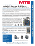
MANUAL
and
WARRANTY REGISTRATION CARD
LS
SERIES
A
NEW
WORLD
®
500W to 1800W WALL MOUNT
Please
Affix
Stamp
Here
[email protected]
email: [email protected]
email:
LATRONICS
P.O. BOX 73
MOFFAT BEACH QLD 4551
AUSTRALIA
POWER
www.latronics.com
web:
web: www.latronics.com.au
6988
5491 6988
7 5491
Ph
Ph 61 7
Latronics P.O. Box 73 Moffat Beach Qld 4551 AUSTRALIA
INSTRUCTION
It is important to us at Latronics, that our clients enjoy the maximum
benefits from our Inverters, in a safe and productive environment.
We strongly advise that you read through the next few pages of this
manual, which explains all the modes of operation and relevant safety
precautions for your new Power Inverter.
If your Inverter requires service or repair please complete the warranty
repair form on page 19-20.
Please remember to complete and return your registration card on the last
page of this manual OR register online to validate your 2-year manufacturers
warranty. Please retain your receipt as proof of purchase.
Latronics products are all proudly designed, engineered and
manufactured in Australia. As a specialist Sine Wave Inverter company we
produce Inverters for a diverse range of applications such as mining,
railways, telecommunications, marine, remote power, motor homes, and
other industrial or commercial installations.
In order to produce highly reliable products, Latronics Inverters have been
designed to endure the most rugged terrain and the harshest conditions
across the Australian continent.
All products are engineered using the latest high quality components and
manufactured to stringent quality standards, so that all Latronics customers
all enjoy many years of trouble free operation.
PH: 61 7 5491 6988
Copyright Latronics
FAX: 61 7 5491 6792
EMAIL: [email protected]
WEB: www.latronics.com.au
Doc No A340-D01-V14-Q2
Version 14 09/13
How do you rate the service from your supplier?
Did your new Inverter meet your expectations?
*
*
* Was your decision made because of?
Features
Value for Money
Appearance
Good
Above Expectations
Fair
Batteries
Yes
Very Good
Warranty
Wind
Commercial
Recommendation
What Energy Source is connected to your Inverter? Solar
*
Residential
Where is your Inverter being used?
*
....................................
Excellent
Australian Made
No
Other
.......................................................................................................................................................................................................
Email / Phone (optional):..................................................................Comments:...........................................................................
Date of Purchase:............................................Supplier:................................................................................................................
Name:....................................................................................Post code:.......................Serial No:.................................................
Your warranty is only valid if this card or online registration is completed within 3 months of the date of purchase.
REGISTRATION CARD
Serial No.................................... Date card returned..............................
As an environmentally conscious customer you may choose to
Register online at http://latronics.com.au. Once completed online,
there is no need to post this registration card.
LATRONICS
PO BOX 73
MOFFAT BEACH Q 4551
IMPORTANT !
WELCOME
TABLE OF CONTENTS
Please provide full description of fault
.................................................................................................
PAGE
INSTALLATION
2
BATTERIES
4
DIP SWITCH SETTINGS
5
AUTOMATIC TRANSFER SWITCH
7
.................................................................................................
INVERTER OPERATION
10
.................................................................................................
EFFICIENCY & OUTPUT WAVEFORM
12
AC WIRING & SAFETY
13
RADIO FREQUENCY INTERFERENCE
14
FAULT FINDING
16
Comments
.................................................................................................
WARRANTY CONDITIONS
17
.................................................................................................
INVERTER SPECIFICATIONS
18
WARRANTY REPAIR FORM
19
.................................................................................................
.................................................................................................
.................................................................................................
.................................................................................................
Please call +61 7 5491 6988 or email [email protected] to
obtain the address of your nearest service center and your RMA
Number which is essential for efficient processing.
RMA Number........................
Have you attached proof of purchase
yes
no
.................................................................................................
.................................................................................................
.................................................................................................
21
REGISTRATION WARRANTY CARD
.................................................................................................
We thank you for your time and patience. This information will help us
determine the cause of failure and possible prevention methods.
®
A
20
NEW
1
WORLD
POWER
INSTALLATION
• Ensure the Inverter has not been damaged in transit.
• The Inverter must not be installed outside
• The unit must be placed in a well-ventilated and protected area, not
exposed to the open environment, and free from contaminates
(i.e. exhaust gases, sea air, battery gases, dust).
• A space of 10cm is needed on each side of the Inverter for adequate
transfer of internal heat.
• The Inverter can be mounted horizontally on a table or floor. The Inverter
can also be mounted on a wall, taking note of the sticker being the
correct orientation.
APPLIANCES
Some appliances may have trouble running on inverters due to the
current waveform they draw.
Certain appliance draw un-even load from a.c. supplies which from a
mains supply might be OK but when operating from an inverter it may
unbalance the internal toroidal transformer which can shut the inverter
down. An example of an un-even current waveform is below
4A
3A
2A
1A
0
-1A
DC WIRING
• For best performance, the unit should be placed as close as possible, but
not directly on top of the battery Supply.
• The Inverter DC input voltage is stated on the identification label of the
Inverter. Check that it is the same voltage as the battery Supply.
• The Inverter is designed to operate on a battery Supply only.
• The Inverter is fitted with a circuit breaker in line with the Battery Positive
Lead, which may reduce the need for a battery Fuse.
• Ensure the Inverter is switched OFF before connecting the DC supply.
Turn the Circuit Breaker switch to the OFF position.
• Connect the Inverter DIRECTLY to the battery Terminals for optimal
performance.
• Input leads marked RED = (positive), & BLACK = (negative).
OBSERVE POLARITY
NOTE: Cables connecting the Inverter to the battery are
designed to achieve maximum efficiency and output power:
DC CABLES SHOULD NOT BE EXTENDED
2
-2A
-3A
-4A
Some appliances that can cause this issue are
• Variable heat guns / hair dryers
• Washing machines / dish washers
This is not to say that the above appliances don’t work, just a very small
amount of models that draw very uneven current.
This imbalance can be evened out by applying more load or trying a
different model/brand.
If you are having trouble with a certain appliance please call Latronics
for further assistance
19
INVERTER MODEL
LS-512
LS-648 LS-1012 LS-1224 LS-1248 LS-1512 LS-1824
LS-624
12V
24V
24V
48V
48V
12V
12V
Nominal DC Voltage
24V
500W
1200W
600W
1200W
600W
1500W
1000W
Continuous Power
1800W
550W
1600W
750W
1600W
750W
1600W
1150W
1/2 Hour Rating
2200W
1500W
3600W
2000W
3600W
2000W
4500W
3000W
Surge Rating (5 Secs)
5400W
10.5-17V 21-34V
42-68V 10.5-17V 21-34V
42-68V 10.5-17V 21-34V
Input Voltage Range
27mA
28mA
22mA
22mA
19mA
42mA
37mA
Standby Current
30mA
0.42A
0.25A
0.31A
0.15A
0.15A
0.67A
0.45A
Inverter ON-no load
0.32A
90%
92%
92%
94%
93%
91%
91%
Peak Efficiency
94%
5.5Kg
11Kg
5.5Kg
11Kg
5.5Kg
14Kg
11Kg
Weight
14Kg
Dimensions
260mm(L) x 160 mm(W) x 100 mm(H)
330mm(L) x 296mm (W) x 150mm (H)
Output Voltage
230Vac +/- 4%
Output Frequency
50Hz +/- 0.1%
Output Waveform
True Sinewave
THD
< 4%
Power Factor
All Conditions
Autostart Sensitivity
0 - 20 W adjustable
Operating Temperature
-100 C to +500 C
DC to AC Isolation
3500 V
Protection Circuitry
Overtemperature, Overload/Short Circuit, Battery Undervoltage/Overvoltage
Battery Leads
1m with 10mm Lugs
1.5m Long with 10mm Mounting Lugs
AC Output Wiring
Single Power Outlet
Single Power Outlet & Junction Box
Chassis
Powder Coated 2mm Aluminium
Powder coated 3mm Aluminium
Warranty
2 Years Parts and Labour
Standards
AS2279, AS3000, AS3100, EN55014, & C-TICK
Ratings
Specifications @ 250 C ambient nominal battery voltage & unity power factor
LS-1848
48V
1800W
2200W
5400W
42-68V
24mA
0.18A
94%
14Kg
INVERTER SPECIFICATIONS
WIRING DIAGRAMS for 12, 24 & 48 Volts DC
12-Volt System
18
+
Due to constant improvements, specifications are subject to change without prior notice.
3
-
24-Volt System
+
+
-
48-Volt System
+
+
-
+
+
N.B. Ensure sufficient battery capacity to match load requirements!
BATTERIES
WARRANTY TERMS AND CONDITIONS FOR AUSTRALIA
BATTERY SIZING
It is important to match your Battery size according to the power rating of
the Inverter.
To ensure peak performance, it is important to choose the right Battery for your
Inverter. The Battery size required will depend on the load and intended
running time. Use this formula as a general guide:
Recommended Battery Size = Inverter rating in watts ÷ input voltage × 10
e.g. ( 1200W ÷ 12V ) x 10 = 1000Ah
Minimum Battery Size = Inverter rating in watts ÷ input voltage × 3
e.g. ( 1200W ÷ 12V ) x 3 = 300Ah.
Do not use an undersized Battery as this may result in an Inverter that does
not start or that will rapidly discharge the Battery and may cause damage to
the Battery.
MAINTENANCE
Battery Terminals require frequent care and maintenance. Very high current
(up to several hundred amps), is drawn by the Inverter when starting electrical
motors and other high power appliances. We recommend an inspection of
the Batteries and the interconnecting cable connections once every 1-3
months or as recommended by the Battery manufacturer.
1. Regularly check all connections; make sure they are always tight.
Battery terminals are made of soft lead which will slowly compress over
time eventually causing loose connections.
2. Check all connections are free of corrosion. Remove any corrosion and
coat the terminals with Vaseline or grease to help prevent future
corrosion.
3. Take specific gravity or SG readings of each cell using a hydrometer to
check the level and performance of each Battery. Alternatively a Battery
Voltage reading for each cell will suffice but may not be accurate for
multiple Batteries connected in parallel. Report any serious imbalance to your
system installer or Battery supplier for corrective action.
SAFETY
When working on Batteries protective clothing and eye wear should be
worn. Extreme care should be taken not to short circuit any Battery
terminals especially with tools. If in doubt have the work carried out by
qualified personnel.
4
Latronic Sunpower Pty Ltd (“Latronics”) provides the original purchaser of a Latronics product (“You”) with the following Limited Warranties as
set out in this warranty certificate, in addition to your rights and remedies under consumer law.
The Limited warranty periods of this inverter is 2 years. In all circumstances Latronics products are guaranteed from the date of purchase.
Part 1 - Warranty Descriptions
Part 2 – Returning a Latronics product for service under warranty.
Latronics warrants to You that our products are guaranteed against
defects in material or workmanship, when in normal use and
service.
If service is required contact your local supplier/installer or place of
purchase for advice.
To Claim Under Warranty:
What you must do
1.You should contact the Customer Care Centre on 1300 550
204. Product Model number and Serial number need to be readily
available to enable prompt processing.
1.For a Limited Warranty to apply the Registration Card must be
validly completed by You and returned, prior to the expiration of 3
months from the date of purchase.
2.You must provide proof of purchase.
3.Latronics recommends You keep your receipt as proof of
purchase, should any difficulties arise concerning the return of your
Registration Card.
Exclusions:
For the avoidance of doubt, the Latronics product warranties
provided herein do not cover damage, malfunctions or service
failures caused by, amongst other things:
•
Unauthorized opening of the products, repair,
alteration or substitution of nonstandard parts;
•
Incorrect design and/or installation of ‘balance
of system’;
•
Acts of god, accident or similar cause;
•
Failure to follow Latronics installation, operation
or maintenance instructions;
•
Abuse, misuse or negligent acts;
•
Power failure surges, lightning, fire, flood, pest
damage, accidental breakage, actions of third
parties and other events or accidents outside
Latronics’ reasonable control and not arising
from normal operating conditions;
•
Suitably qualified personnel not carrying out all
AC and DC permanent wiring in accordance
with relevant wiring rules.
Products supplied by Latronics, or Latronics agents are supplied
under the express condition that no responsibility is implied or
accepted by Latronics for any damage to any appliance,
equipment or property used in combination with the correct
operation of a Latronics product.
All conditions and warranties expressed or implied by statute,
common law, equity, trade, custom, usage, or otherwise
howsoever are hereby expressly excluded to the maximum extent
permitted by law. Where so permitted, the liability of Latronics for a
breach of condition or warranty that cannot be excluded is limited
(at Latronics option) to the replacement or repair of the goods or
of acquiring equivalent goods or the cost of replacing or repairing
the goods or of acquiring equivalent goods.
Latronics does not undertake any commitment to guarantee
continuity of supply in the case of obsolescence. In addition,
Latronics reserves the rights to change its standard product range
or specification of any model subsequently without notice and no
liability as a result of these occurrences will be accepted.
2.If, after investigation, the Customer Care Centre determines the
product is or may be defective in material or workmanship and
within the warranty period, they will issue instructions on how to
proceed with return and shipping to Latronics.
3.When packaging a Latronics product for return appropriate
measures must be taken by You to ensure the products are safely
packed for transit. Products damaged in transit due to inadequate
packaging will be void of warranty.
4.If the product manual has a Warranty Return Form included, this
form should be completed and accompany products being
returned.
5.If, as a result of further investigation by or on behalf of Latronics,
such a defect is confirmed, then Latronics must, at its sole
election, either repair or replace your Latronics product. Latronics
will also, at their discretion, determine the most appropriate
means to return any Warranty repairs (or replacements) to You in a
timely manner.
Part 3 - General Information
Replacement of any part or labour involved in repairs will not have
the effect of extending the original period of the Limited Warranty
of the goods. Any faulty part replaced under Limited Warranty
becomes the property of the Company for purpose of
examination and claim under proprietary warranty.
Under these product warranties, Latronics is not responsible for and
you hereby agree to bear any costs associated with removal,
transportation or reinstallation of your Latronics products or any
peripheral components in the balance of any system used in
conjunction with Latronics products.
Products returned to Latronics without prior authorisation will be
returned to the sender at their expense.
All Warranty repairs are completed ex-factory to ensure
•
Fast service turn around time
•
Specialised, factory trained technicians
•
All required components are available (except
in the case of obsolescence)
•
Thorough testing to all Latronics specifications
•
Dedicated test equipment
•
Upgrades/updates to latest Latronics
standards/specifications (where applicable).
Our goods come with guarantees that cannot be excluded under the Australian Consumer Law. You are entitled to a replacement or
refund for a major failure and compensation for any other reasonably foreseeable loss or damage. You are also entitled to have the goods
repaired or replaced if the goods fail to be of acceptable quality and the failure does not amount to a major failure.
17
FAULT FINDING
Should the Inverter appear to be malfunctioning we suggest the
following to eliminate any external problems:
1.
Turn the Inverter “OFF” via the Circuit Breaker switch on the front panel.
2.
Disconnect all AC wiring from the Inverter.
3.
Disconnect DC Battery leads from Battery. Clean all terminals by
removing all grease/corrosion on both DC leads and Battery
terminals.
4.
Ensure you have sufficient Battery capacity at the nominal voltage
(specified on the compliance label of your Inverter).
Please note: Use minimum 100AH Battery or the size of
a substantial Car Battery.
5.
Make connection directly to Battery terminals and ensure all
connections are tight.
6.
Remove other wiring from battery to ensure that the Inverter is the ONLY
device connected to battery bank
7.
Ensure Battery voltage is within the correct limits as outlined in the
section INVERTER SPECIFICATIONS of this manual. If you do not have a
DC voltmeter or multimeter check the front panel for Overvolts and
Undervolts LEDs.
8.
Turn the Inverter ON via the Circuit Breaker switch on the front panel.
Observe the lights on the front left of your Inverter. Refer to INVERTER
OPERATION sections for explanation of Indicator lights.
9.
Plug in various appliances and monitor the Inverters operation.
HELPFUL HINTS
*
Remember that the Inverter automatically starts when a load is
applied.
*
Make sure leads and terminals are not corroded or faulty in any way.
*
Make sure the Inverter goes into STANDBY with no load switched on.
*
Make sure the Circuit Breaker is reset properly. If unsure switch OFF and
ON again.
*
In extreme weather it is suggested to shutdown and unplug the unit.
16
DIP SWITCH SETTINGS
Dip switch settings apply to all models from 1000W-1800W inclusive.
In order to access these options you have to open the Inverter. Before
altering the settings switch the Inverter OFF, adjust the setting and switch the
Inverter back ON again. We recommend these adjustments be carried out by
qualified personnel or your system installer.
SW1
Hz
50/60 Hz
ON = 50Hz (factory setting) OFF =60Hz
If you need to operate American or Japanese equipment this option will
allow your Inverter to operate at 60Hz.
SW2 & SW3
SW4
SP
Special
AR
Automatic Reset
OFF=Disabled
ON=Enabled (factory setting)
This feature is designed to restart the Inverter and maintain power in the event
of an external fault. Should the Inverter shut down due to under voltage, over
temperature or any fault condition it will attempt to reset every 8 minutes until
the fault condition clears and normal operation resumes.
For overload shutdown the Inverter will only attempt 5 restarts. If the Inverter
can not resume normal operation within 5 restarts, it will remain OFF until reset
manually. This prevents continuous re-application of power to faulty
appliances or wiring.
For under voltage shutdown the Inverter will restart when the battery voltage
reaches the reconnect value as shown in the table below.
SW5 & SW6
UV
Under Voltage Settings
SW5 OFF & SW6 OFF= (factory setting)
Setting
SW5
SW6
ON
OFF
ON
OFF
ON
OFF
OFF
ON
12V Value
Disconnect Reconnect
10.0
10.5
11.0
11.5
12.0
12.5
13.0
13.5
24V Value
Disconnect Reconnect
20.0
21.0
22.0
23.0
5
24.0
25.0
26.0
27.0
48V Value
Disconnect Reconnect
40.0
42.0
44.0
46.0
48.0
50.0
52.0
54.0
DECLARATION OF CONFORMITY
DIP SWITCH LOCATION
Manufacturer:
Latronic Sunpower Pty Ltd
105 Grigor St West
Moffat Beach Industrial Park
Caloundra Queensland 4551
Australia
MAIN PCB
Declare that the LS series of inverters conform to the requirements of following
standards
1
2
3
4
5
6
OFF
DIP Switch located on Main PCB
EN61000-6-1
EN61000-6-3
EN55014
AS1044
EN60335-1
AS3100
And therefore conform to the regulations of the EC directives
Directive 2004/108/CE (EMC directive), Directive 2006/95/CE (low Voltage
Directive)
Date that CE marking was first affixed 2007
ON
Also conforms to the regulations of C-tick mark for Australian emission standards
WARNING:
Due to dangerous voltages existing inside the unit, make sure the
circuit breaker switch is turned off before opening the unit. Should
you have any doubt about performing these modifications, we
strongly recommend the use of a qualified trades person.
All products are manufactured with full traceability in accordance with the
Quality System Requirements of AS/NZS ISO 9002
Signed
William Pettit
Electronic Engineer
th
24 Oct 2011
6
15
RADIO FREQUENCY INTERFERENCE
Radio Frequency Interference (RFI) is a phenomenon that exists in modern
society and is a problem in many areas of electronics. For Inverter users,
RFI normally presents itself in the form of static and/or interference when
listening to an AM radio and in unusual cases may interfere with TV reception.
Over the years Latronics has continued to invest significant time and effort in the
reduction of RFI related emissions from the entire product range, so that they
comply with the appropriate International and/or Australian Standards.
Even with this compliance, there are situations where RFI may still be a cause for
concern, and can differ greatly from installation to installation. Accordingly, the
following is a list of recommendations made to assist in the overall reduction of
RFI.
Separate DC and AC wiring. Avoid running DC and AC cables in the
1.
same conduits and/or cable trenches. It is strongly recommended that
DC and AC wiring be separated by the greatest distance possible. In
extreme cases, the use of shielded conduit may be necessary.
2. Minimize length of DC cabling. DC cables can act as an aerial, therefore
all such cables should be kept as short as is practicable. For best
performance minimize DC cable length to Inverter and Batteries and if
possible avoid the use of auxiliary DC loads.
240Vac Earth. For household installations, it is recommended that a
3.
“good” Earth Stake is located as nearby the Inverter as is possible.
AM and HF Radios. These types of radio equipment inherently suffer
4.
from all forms of RFI, especially when the received signal level is weak.
In such cases reception can sometimes be improved by relocation of
the radio itself, alternatively the use of an appropriate external antenna
and co-axial cable may be necessary. External antennas should be
located in a manner that ensures maximum signal strength whilst affording
the greatest possible distance away from the Inverter and Batteries.
Televisions. TV signals are transmitted as FM waveforms. This type of signal
5.
fundamentally reduces the effects of RFI, therefore the use of a good
antenna and feeder cable is normally sufficient to ensure quality reception.
Locating the television as far as possible from the Inverter may also improve
picture clarity.
6.
Mobile Installations. Due to the limitations of this type of installation, the
best results for the minimization of RFI are usually obtained by maximizing
the distance between the Inverter and the Radio/Television.
AUTOMATIC AC TRANSFER SWITCH
(Option)
Eliminates the need to manually switch your power source between
Inverter and Generator. The Transfer Switch automatically senses
Generator AC power and switches the output between Inverter and
Generator accordingly.
Features
*
Available exclusively to the LS series from 1000W to
1800W models.
*
No Break changeover time of 0.02 second (< one cycle).
*
Double pole contactor switching both active and neutral.
Please Note: The AUTOMATIC AC TRANSFER SWITCH is now available as a
separate device in a 2 (ACTS40) or 3 (ACTS3) way version.
If you do not have a Latronics transfer switch but another manual or
automatic switch, please ensure you wait 5 seconds between switching
from one source to another. Fash switching may damage the inverter.
SYSTEM BLOCK DIAGRAM
Solar
Panels
AC Loads or
Distribution
Regulator/Controller
Batteries
AC Output
Inverter
Battery
Charger
AC Input
Generator
or Aux AC
Installation of system components and associated interconnecting wiring,
should be performed by qualified and licensed personnel only.
14
7
SAFETY
Inverter Isolation and Safety
Notes:
......................................................
......................................................
......................................................
......................................................
......................................................
......................................................
......................................................
......................................................
......................................................
......................................................
......................................................
......................................................
......................................................
......................................................
......................................................
......................................................
8
*
*
*
*
All standard Latronics Inverters have an isolation rating of 3500V
between AC and DC via the toroidal transformer, which ensures
extremely safe and risk free operation.
When switching the output of the inverter ensure that the switch is a
double pole switching device switching both active and neutral.
All the switching electronics and control circuitry are on the DC input.
The single pole Circuit Breaker assembly ensures that when the
Inverter is switched OFF, it is isolated from the Battery supply.
Please refer to relevant Australian Standards for safety procedures.
AC WIRING
*
*
*
*
*
*
Make sure the Inverter is switched OFF before working on the mains
wiring. Turn the circuit breaker switch into OFF position.
In standard Latronics inverters the active and neutral of the 230V AC
output are electrically isolated from the battery negative, battery
positive, and earth connections.
The Inverter AC output is connected directly to the Transformer output
winding.
Standard Latronics Inverters have the AC output (active and neutral)
floating with respect to the DC and Earth. The Earth connection is
connected to the case only. This configuration provides the highest
safety and most flexibility for installation wiring.
Latronics Inverters are suitable for MEN connection.
The Earth is connected internally to the Inverter case.
Ensure that power will never be fed into the Inverter AC output Junction Box
from the Mains or Generator. This would result in the destruction of the unit
and will not be covered by warranty.
WARNING:
The Inverter output is just as lethal as normal mains electricity
It is important that all AC wiring complies with the requirements of the
relevant wiring standards, (AS 3000).
Any work carried out on AC/Mains wiring is to be performed by
Qualified and Licensed personnel only.
13
High efficiency
even @ low levels
Efficiency
INVERTER EFFICIENCY & OUTPUT WAVEFORM
400
300
AC Voltage
200
100
0
-100
-200
-300
Notes:
......................................................
......................................................
......................................................
......................................................
......................................................
......................................................
......................................................
......................................................
......................................................
......................................................
......................................................
......................................................
......................................................
......................................................
......................................................
......................................................
-400
12
9
INVERTER OPERATION
When the Inverter is switched on all 3 LEDs light up for 1 second while the microprocessor performs a start up and system check procedure.
Over temp./Over load (Red LED)
If the internal temperature exceeds safe
operating limits of the components for more
than five seconds, the Inverter will shut down in
Over temp with this LED on continuously.
Allow 5 minutes for the Inverter to cool and reset
the unit. If the APPLIED load demands more
current than the Inverter can safely supply for
more than 5 seconds, the Inverter will shutdown
in Over load and this LED will flash.
Standby/240 volts (Green LED)
This LED flashes when in Standby mode
(i.e. no loads connected). When a load
is applied the LED will illuminate
continuously to indicate that 240V AC is
being supplied.
Circuit Breaker ON/OFF Switch
The circuit breaker is designed for ease of
operation and safety. By pushing the switch
“UP”, the battery supply is connected to the
Inverter. The circuit breaker will turn OFF
automatically or the Overload LED will
illuminate if too large a load is left on the
Inverter continuously. Reset the switch after
allowing approximately 5 minutes to cool. If
the Inverter shuts down due to Undervolts or
Overvolts it can be reset by turning the
circuit breaker OFF, waiting 10 seconds (or
until LED goes out), then turning it on again.
Hardwire- 3 Terminal
Output Junction Box
For distribution of AC
output power.
1000W - 1800W
Models only.
Undervolts/Overvolts (Red LED)
In order to protect the battery the Inverter will
shutdown after 5 seconds if the battery
voltage falls below its limit, (Undervolts), or
exceeds the maximum, (Overvolts), as
specified in the Electrical Specifications table.
For Undervolts the LED will remain on continuous,
while for an Overvolts situation the LED will
continue to flash.
Battery leads
DC leads RED = battery
positive, Black = battery
negative.
Power Outlet
Single unswitched socket
AutoStart Sensitivity Adjustment
The screwdriver adjustment slot permits
the operator to adjust sensitivity between
0- 20W. Due to lengthy AC cables the
Inverter may sense fake loads. To combat
this, turn the control clockwise. Alternatively
turning the control in the opposite direction
increases sensitivity. Turning the control fully
anti-clockwise will disable the Auto Start feature
and the Inverter will remain constantly ON.
Fan
If the temperature inside the inverter reaches
preset levels, the dual speed fan will switch
on initially in low speed and then into high
speed if the temperature continues to
increase. Obstruction of the air intake and
output will reduce the power rating of the
Inverter.
Hardwire-3 Terminal
Input Junction Box
For connection of AC Input Power
eg. from generator.(Available only
when AC Transfer Switch option is
fitted).
1000W - 1800W
Models only.