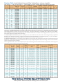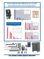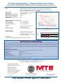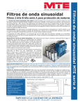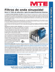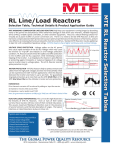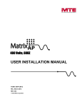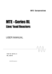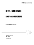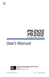
1
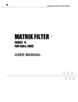
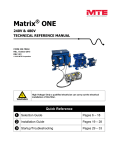
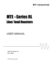
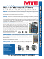
Series D - Selection Table & Technical Specifications Guide
IEEE-519 - The Series D Matrix® Harmonics Filter uses patented Harmonics Mitigating Reactor (HMR) technology
to limit full load current distortion to less than 5% THID on virtually any kind of six pulse rectifier supply. Six pulse
rectifiers are commonly found in three phase electronic equipment such as adjustable speed motor drives, welders,
battery chargers, servo drives and other electronic equipment. Matrix® Filters enable your system to meet the voltage
and current distortion limits of IEEE-519, EN61000, AS2279 and G5/4.
Reliability - Harmonic currents reduce equipment life, electrical system reliability, system efficiency and equipment
productivity. Matrix® Filters reduce the burden on electrical equipment by reducing TRUE RMS current, peak current and
harmonic frequency distortion. The series impedance included in the Matrix® Filter also absorbs transient over-voltages just like
a line reactor, to prevent over-voltage trips and rectifier damage. Matrix® Filters also reduce the TRUE RMS current that flows
through equipment feeding non-linear loads. This reduces the amount of heat generated by upstream equipment (such
as transformers, disconnects, fuses, circuit breakers and conductors), extending their life expectancy. Increased
system reliability leads to higher productivity for your overall system.
MDP0482D
Performance, Guaranteed! - Matrix® Harmonic Filters can meet or exceed
the harmonic mitigation performance of other common filtration methods. Unlike
alternative solutions, Matrix® Filters come with a performance guarantee. The
Series D Matrix® Filter allows users to achieve superior attenuation of harmonics
when used with 6 pulse drives and will outperform techniques using 12-pulse or
18-pulse rectification methods. The new patented HMR (Harmonic Mitigating
Reactor) optimizes the technology for smaller packaging requiring less floor or
panel space than other filter schemes. On AC variable frequency, variable torque
drive applications (fans & pumps), Matrix filters will meet the guaranteed maximum
levels of THID (total harmonic current
distortion) at full load. Unlike other harmonic
filter technologies, the performance of MTE
Matrix Harmonic Filters is guaranteed!
Installation Options - Matrix Harmonic Filters are available in a variety of enclosure
options. The standard enclosure meets the requirements of both Nema 1 & Nema 2. The Nema
3R enclosure provides weather protection and is available in optional stainless or galvanized
steel construction. Optional Serpent/Rodent screens can be added to block small animals from
entering enclosures.
For maximum flexibility, Matrix filters are also offered as open modular construction for
integration into customer enclosures and panels.
Electrical Options - Various contactor options may be added to provide for filter bypass
and leading KVAR cancellation to enhance compatibility with standby power and support service
requirements.
MDG0103D
Typical Uses Include:
• Mission Critical Facilities
• AC Variable Frequency Drives
• DC Adjustable Speed Drives
• Electronic Welders
• Battery Chargers
• Fans and Pumps
• Water Treatment Facilities
• Induction Heating Equipment
• Elevator Drives
• Any 6 Pulse Rectifier Supply
The Matrix Filter is designed to be installed on the line side
of a drive and deliver guaranteed IEEE-519 performance.
The Global Power Quality Resource
MTE Corporation - Menomonee Falls, WI - 1-800-455-4MTE - www.mtecorp.com
MTE Matrix® Filter Selection Tables
Matrix® Harmonic Filters
Selection Table Series D Matrix® Harmonic Filter Technical Data - 208, 240, & 400VAC
Note: replace “_” with P for open panel, “G” General NEMA 1-2 and “W” weather NEMA type 3R in Base part number
Refer to Page 4 for Figures, Cabinet information, and Option details
Matrix® Filters for Variable Torque AC Drives rated 7.5 Hp and above should be selected for a filter output current rating greater than or equal to the motor
current rating. If the motor current rating is not available, use the NEC motor current rating. AC drives rated 2 – 5 Hp should be selected for a filter output
current rating greater than or equal to 105% of the motor current rating. If the motor current rating is not available, select on the basis of 105% of the NEC
motor current rating. For those AC drives rated less than 1.5 Hp selection should be based on an output current rating greater than or equal to 110% of the
motor current rating or 110% of the NEC motor current rating.
For Constant Torque AC and DC Drive applications operating from six pulse rectifier front ends, select a filter current rating according to application
engineering note “Matrix Filter Operation in Constant Torque Applications with Six Pulse Rectifiers” or consult MTE engineering. For phase controlled DC
drive applications, select filter current rating per application note “Matrix Filter with Phase Controlled DC Driver.”
The Capacitor Contactor Option is recommended for generator applications where the kVA rating of the generator is less than 1.20 times the kVA rating of the
Matrix® Filter. Calculate the kVA rating of the Matrix® Filter based on the input voltage rating and the output current rating. Contactor is sized to the filter
capacitor current as listed in the user manual.
Where a single Matrix® Filter is used to feed multiple drives, the output current rating of the filter should be selected to equal the total current rating of the
individual drives when calculated according to the instructions above.
The Global Power Quality Resource
MTE Corporation - Menomonee Falls, WI - 1-800-455-4MTE - www.mtecorp.com
Selection Table Series D Matrix® Harmonic Filter Technical Data - 480 & 600VAC
Note: replace “_” with P for open panel, “G” General NEMA 1-2 and “W” weather NEMA type 3R in Base part number
The Global Power Quality Resource
MTE Corporation - Menomonee Falls, WI - 1-800-455-4MTE - www.mtecorp.com
Enclosure & Electrical Options Series D Matrix® Harmonic Filters
Figure 1 - General Purpose Enclosure
NEMA 1, 2, & 3R
Enclosure Options - Series D Matrix® Harmonic Filters
Option -100 - NEMA 3R enclosure with high endurance white paint: These galvanized enclosures are supplied with continuous welds on the
top cover and weather shields. Exterior hardware is supplied with gaskets.
Option -200 - NEMA 3R STAINLESS STEEL enclosure with high endurance white paint: These enclosures are constructed from 316L stainless
alloy using stainless steel hardware. Gaskets are applied to weather proof exterior components. The exterior surfaces of the enclosure are
finished in high endurance white polyester powder coat.
Option -300 - Standard Grey enclosure with optional Serpent/Rodent screens: Provides intake exhaust air screens with (¼in X ¼in) mesh
openings.
Option -400 - NEMA 3R enclosure with high endurance white paint plus Serpent/Rodent screens: This option incorporates air intake screens
with ¼in X ¼in mesh openings with the white painted NEMA 3R enclosure of Option -100.
Option -500 - NEMA 3R STAINLESS STEEL enclosure with high endurance white paint plus Serpent/Rodent screens: This option incorporates
air intake screens with ¼in X ¼in mesh openings with the white painted NEMA 3R enclosure of Option -200.
Figure 3 Capacitor Assemblies
Figure 2 Open Magnetics
Electrical Options - Series D Matrix® Harmonic Filters
Option -002 - Capacitor Contactor: This option provides a contactor to disconnect the filter capacitor bank (KVAR current becomes zero)
when the drive is not running. The contactor is supplied with NO/NC auxiliary contacts. The contactor coil and auxiliary contacts are wired to a
customer terminal block. A 120Volt 60Hz power source is required for this option.
Option -012 is a self powered version.
Option -009 - Capacitor Contactor with adjustable pick-up and drop-out: This option provides a contactor to disconnect the filter capacitor
bank based on the motor load current. Two current operated switches provide independent adjustment of the pick-up and drop-out current
levels. The switches are preset at the factory for pick-up at 50% and drop-out at 20% of the filter output current rating. The switches are field
adjustable over a 0% to 100% current range. This option includes a 120VAC control transformer.
Option -010 - Filter Bypass: The filter bypass option is designed to provide filter bypass for drives that have an integrated bypass option as
typically found in HVAC applications. Filter bypass is initiated by a contact closure when the motor is switched to operate directly from the AC
line instead of the drive. A 120VAC control power source is required.
Option -011 is a self powered version.
Option -013 - Filter bypass and capacitor contactor with control transformer: This option combines the filter bypass (Option -010) with a self-
powered customer controlled capacitor disconnect contactor (Option -012). A jumper selection provides single contact switching for normal
bypass control with capacitor removal.
The Global Power Quality Resource
MTE Corporation - Menomonee Falls, WI - 1-800-455-4MTE - www.mtecorp.com
See the Matrix® Filter difference for yourself!
Compare the difference in waveform and harmonic spectrum for real life tests
performed at full load conditions for various harmonic mitigation techniques.
Distortion
MTE Matrix® Filter
Harmonic
12 Pulse
5th Harmonic Trap
w/5% Line Reactor
Distortion
Matrix® Filters attenuate harmonics better
than these alternative filtering techniques.
Data based on actual tests at full load power.
Harmonic
Distortion
Distortion
18 Pulse
Harmonic Order
Part Number Code:
Harmonic
MD X _ _ _ _ X _ _ _
Product Code Matrix Series D
Type
PPanel Mnt GGeneral Purpose NEMA2 WWeather NEMA3R
Current Rating
00066 amps 0786786 amps
Voltage Frequency Code
C380VAC - 415VAC 50Hz D480VAC 60Hz
Enclosure Options
Contactor Options
The Global Power Quality Resource
MTE Corporation - Menomonee Falls, WI - 1-800-455-4MTE - www.mtecorp.com
Product Specifications - Matrix® Harmonic Filters
Refer to the MTE SERIES D MATRIX® HARMONIC FILTER User Manual for Detailed Specifications
Matrix Filters are designed to operate and will achieve guaranteed performance under the follow conditions:
Load: 6 pulse rectifier, operating in variable torque mode and chosen from the
standard selection table. For constant torque application select filter rating
based on appropriate application note: AN-0106
Input voltage: Nominal voltage VAC +/- 10%, 3 Phase
Frequency: Nominal Frequency + .75 Hz
Input voltage line unbalance: 1% maximum
Maximum source impedance: 6.00%
Minimum source impedance: 1.5%
Service Factor: 1.00
Ambient Temperature (Operating)
Enclosed Filters: -40 to +40 degrees C
Open Panel Filters: -40 to +50 degrees C
Storage Temperature: -40 to +90 degrees C
0 to 3300 Feet above sea level
without derating
0 to 95% non-condensing
Agency Approvals
UL and cUL listed :
UL508 and CSA-C22.2 No 14-95
File E180243 (3HP to 1000HP,
120VAC to 600VAC, 50Hz, 50/60Hz,
& 60Hz Three Phase)
Performance
Total Harmonic Current Distortion: 5% MAX at FULL LOAD
Matrix Series D Filter
Typical Harmonic Spectrum For 100% Load
Harmonic
Current %
Altitude: Relative Humidity: 4
3
2
1
0
5
7
11
13
Harmonic
17
19
23
25
Performance Guarantee
Select & install the appropriate Matrix Harmonic Filter in a variable torque AC variable frequency drive application, within our published system limits & we
guarantee that the input current distortion will be less than or equal to 5% THID for MD Series filters at full load. If a properly sized & installed filter fails to
meet its specified THID level, MTE will provide the necessary modifications or replacement filter at no charge. TDD will typically be even lower than THID.
Matrix filters can also provide similar performance in other drive applications such as constant torque, DC drives & other phase controlled rectifiers, but
actual THID levels can vary by load and/or speed & therefore cannot be guaranteed. Consult factory for assistance when applying Matrix filters on these
types of equipment
MINIMUM SYSTEM REQUIREMENTS:
The guaranteed performance levels of this filter will be achieved when the following system conditions are met:
Source impedance: 1.5% minimum to 6.0% max
Frequency: 60Hz ± 0.75Hz
System Voltage: Nominal System Voltage (line to line) ±10%
Balanced Line Voltage: within 1%,
Background Voltage Distortion: 0% THVD.
NOTE: The presence of background voltage distortion will cause motors & other linear loads to draw harmonic currents. Additional harmonic currents may flow
into the Matrix filter if there is harmonic voltage distortion already on the system.
For Technical Support: [email protected]
For Sales Support: [email protected]
World Headquarters
N83 W13330 Leon Road
Menomonee Falls
Wisconsin 53052
Toll Free 1-800-455-4MTE
Phone: (262) 253-8200
Fax: (262) 253-8222
Form 1217B-1-08
®
Visit us on the Web at:
www.mtecorp.com
© 2008 MTE Corporation
All Rights Reserved
The Global Power Quality Resource