1
7KH'3,&(ZLWK:L)L
Advanced Modular Calibrator and HART Communicator
$ZLUHOHVV,(((JHQDEOHG0XOWLIXQFWLRQ(OHFWULFDO&DOLEUDWRUDQG+$57&RPPXQLFDWRU
1RWDYDLODEOHZLWKWKH,6YHUVLRQ
7KH'3,&(YHUVLRQFDQEHIXUWKHUHQKDQFHZLWKZLUHOHVV,(((JFRPPXQLFDWLRQV)RUWKH¿UVWWLPHLQDFDOLEUDWRURIWKLV
W\SHLWLVSRVVLEOHWROLQNWRWKH,QWHUQHWDQGUHPRWHQHWZRUNVLQRUGHUWRDFFHVVLQIRUPDWLRQDQGWRWUDQVIHUGDWD7KLVSRZHUIXO
IHDWXUHZLOOEHQH¿WVHUYLFHWHFKQLFLDQVZKRVSHQGH[WHQGHGSHULRGVDZD\IURPKHDGRȻFHDQGIRUWKRVHZKRQHHGLQVWDQW
DFFHVVWRGDWDVDIHW\LQIRUPDWLRQV\VWHPGUDZLQJVSURGXFWGDWDVKHHWVHWFZKLOHRQWKHPRYH,WZLOODOVRSURYLGHDQLQWHUIDFHWRIXWXUH
system modules when a physical connection is a hindrance.
7HFKQLFDO6SHFL¿FDWLRQV
'3,&(*HQHUDO6SHFL¿FDWLRQV
6L]HPPLQGLDJRQDO[SL[HOV
/&'&RORXUGLVSOD\ZLWKWRXFKVFUHHQ
/DQJXDJHV
(QJOLVK^'HIDXOW`&KLQHVH)UHQFK*HUPDQ,WDOLDQ3RUWXJXHVH5XVVLDQ6SDQLVK
Operating temperature WR&WR)
Storage temperature
WR&WR)
Ingress Protection
,3'XVWWLJKWMHWVRIZDWHU
Humidity
WR5+1RQFRQGHQVLQJ
6KRFN9LEUDWLRQ
%6(1'HI6WDQFDW,,,P'URS7HVWHG
EMC
(OHFWURPDJQHWLFFRPSDWLELOLW\%6(1
Electrical safety
(OHFWULFDO²%6(1
Pressure safety
3UHVVXUH(TXLSPHQW'LUHFWLYH&ODVV6RXQG(QJLQHHULQJ3UDFWLFH6(3
Approved
&(0DUNHG
6L]H/:+
'3,RQO\[[PP[[LQ0&§[[PP[[LQ
30§[[PP[[LQ
:HLJKW
'3,RQO\§JOE²EDWWHU\LQFOXGHG0&RQO\§JOE30RQO\§JOE
Power supply
/LWKLXP3RO\PHUEDWWHU\*(3DUWQXPEHU,2%DWWHU\&DSDFLW\P$KPLQLPXPP$KW\SLFDO1RPLQDOYROWDJH
9&KDUJHWHPSHUDWXUHWR&WR)'LVFKDUJHWHPSHUDWXUHWR&WR)
Note: For best battery performance, keep the temperature less than 60°C (140°F). &KDUJHGLVFKDUJHF\FOHV!!FDSDFLW\
Duration
0HDVXUHIXQFWLRQV&+§KRXUVFRQWLQXRXV'XDO)XQFWLRQP$PHDVXUH&+§KRXUV96RXUFHDWP$
Display
'3,,6DQG'3,,6&(&DOLEUDWRU*HQHUDO6SHFL¿FDWLRQV
6L]HPPLQGLDJRQDO[SL[HOV
2/('&RORXUGLVSOD\ZLWKWRXFKVFUHHQ
/DQJXDJHV
(QJOLVK^'HIDXOW`&KLQHVH)UHQFK*HUPDQ,WDOLDQ3RUWXJXHVH5XVVLDQ6SDQLVK
Operating temperature WR&WR)
Storage temperature
WR&WR)
Ingress Protection
,3'XVWWLJKWMHWVRIZDWHU
Humidity
WR5+1RQFRQGHQVLQJ
6KRFN9LEUDWLRQ
%6(1'HI6WDQFDW,,,P'URS7HVWHG
EMC
(OHFWURPDJQHWLFFRPSDWLELOLW\%6(1
Electrical safety
(OHFWULFDO²%6(1
Pressure safety
3UHVVXUH(TXLSPHQW'LUHFWLYH&ODVV6RXQG(QJLQHHULQJ3UDFWLFH6(3
Approved
&(0DUNHG
6L]H/:+
'3,RQO\[[PP[[LQ0&§[[PP[[LQ
30§[[PP[[LQ
:HLJKW
'3,RQO\§NJOE²EDWWHU\LQFOXGHG0&RQO\§JOE30RQO\§JOE
Power supply
1L0+EDWWHU\*(3DUWQXPEHU,2,6%DWWHU\&DSDFLW\P$KW\SLFDO1RPLQDOYROWDJH9&KDUJHWHPSHUDWXUHWR
&WR)'LVFKDUJHWHPSHUDWXUHWR&WR)
Note: For best battery performance, keep the temperature less than 60°C (140°F). &KDUJHGLVFKDUJHF\FOHV!!FDSDFLW\
Duration
0HDVXUHIXQFWLRQV&+§KRXUVFRQWLQXRXV'XDO)XQFWLRQP$PHDVXUH&+§KRXUV96RXUFHDWP$
Approval
%DVHHID$7(;;
,(&([%$6;
([,,*
([LD,,&7*D&7D&
(1
(OHFWULFDODSSDUDWXVIRU3RWHQWLDOO\([SORVLYH
$WPRVSKHUHV²*HQHUDO5HTXLUHPHQWV
+DUPRQL]HG
,(&(GLWLRQ
(1
(OHFWULFDODSSDUDWXVIRU3RWHQWLDOO\([SORVLYH
$WPRVSKHUHV²,QWULQVLF6DIHW\¶L·
+DUPRQL]HG
,(&(G
Display
6
Pressure measurement
for research & industry
Druck Limited
Fir Tree Lane
Groby
Leicester LE6 0FH
England
Tel: 0116 231 7100
CERTIFICATE RELATED DRAWING
NOT TO BE MODIFIED WITHOUT
THE APPROVAL OF THE CERTIFICATION ENGINEER
APPROVED:
CERTIFICATES:
M T CONCANNON
Baseefa10ATEX0010X
Baseefa10ATEX0012X
IECEx BAS 10.0002X
IECEx BAS 10.0004X
DPI 620-IS
Advanced Modular Calibrator
Safety and quick reference guide
K0461
© Druck Limited 2010
This document is the property of Druck Limited and may not, either in part or whole, be copied or otherwise reproduced,
communicated in any way to third parties, nor stored in any data processing system, without the express written authority of
Druck Limited.
Page 1 of 22
K0461 Issue 1
Amendment Record
Iss No
1
Date
18/06/10
C/N No
Originator
N/A
Robert Lee
Typed
Robert Lee
Workflow
No.
147821
Amendments
New document
Approvals
Engineering
G DOCHERTY
Marketing
Technical Communications
M SHELTON
R LEE
Page 2 of 22
K0461 Issue 1
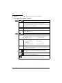
Print Instructions: K0461, Issue 1
1) Print Instructions
2) Front + Back Cover
3) Main body
DO NOT PRINT
1 leaf (2 pages) – printed both sides and fold
Text (8 leaves (16 pages) – printed both sides)
Specification:
•
Finished Size: A5 Portrait (148 x 210 mm)
•
Print in colour throughout (Covers + text)
•
2 page front + back cover (1 leaf) with throw-clear illustrations to 150 gsm
(420 mm folded to A5 – Graphics A2-A5, B1 on
reverse)
•
8 pages main body (4 leaves) Text to 100 gsm
•
Saddle stitched
THIS HARDCOPY IS NOT TO BE USED AS CAMERA COPY.
Page 3 of 22
K0461 Issue 1
Page 4 of 22
K0461 Issue 1
safety and quick reference guide - K0461
advanced modular calibrator
Druck DPI 620-IS
GE
Sensing & Inspection Technologies
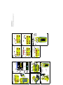
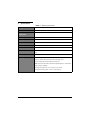
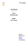
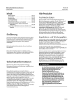
A1.1
DPI 620-IS: Channel 1 (CH1)
±2000 mV (M)
0 to 2000 mV (S)
Switch (M)
±2000 mV (M)
Figure C3 (2, 3, 4-wire)
Figure C4
Figure D1
All product names are trademarks of their respective companies.
Trademarks
© 2010 General Electric Company. All rights reserved.
* Caution: To prevent damage to the PM 620-IS module, only
use it within the specified pressure limit on the label.
Gauge: 25 mbar to 200 bar (0.36 to 3000 psi)
Absolute: 350 mbar to 1000 bar (5 to 15000 psi)
Note: Maximum pneumatic pressure: 500 bar (7250 psi)
Figure E1
DPI 620-IS + MC 620-IS + PM 620-IS
Pressure* (M)
A1.3
p Switch (M)
o 24 V loop (P)
n 0 to 24 mA (S)
m ±55 mA (M)
l
k ±30 V (M)
= See figure or
Figure C2
Note:
table.
Figure C1
DPI 620-IS: Channel 2 (CH2)
12 TCs (M/S)
j
A1.2
11 RTDs (M/S)
i
h 0 to 24 mA (S)
g ±55 mA (M)
f
e 50 kHz (M/S)
d 0 to 4000 Ω (M/S)
c
b 0 to 12 V (S)
a ±30 V (M)
Measure (M) / Source (S) / Power (P)
1
A2.2
2
K0461 Issue 1
B2
A3
1
A2.1
3
3
b
a
5
4
b
1
2
2
6
a
DPI 620-IS
4
DPI 620-IS
B1
2
1
3
e
a
c
d
DPI 620-IS
b
4
2
1
3
5
MC 620-IS + PM 620-IS
DPI 620-IS +
MC 620-IS +
PM 620-IS
9
8
7
A2.2
a
f
A1.1 ( i )
mV, V, mA
24 Vo
DPI 620-IS: CH2
DPI 620-IS: CH1
A1.1 ( a, b, c, d, e, f )
DPI 620-IS: CH1
A1.2 ( l, m, n, o, p, q )
D1
C3
V, mV, Ω, Hz,
C1
E1
C4
C2
A1.1 ( j )
DPI 620-IS: CH1
A1.1 ( g, h )
A1.3
P1
P2
DPI 620-IS + MC 620-IS + PM 620-IS
mA
DPI 620-IS: CH1
C
4
Visit our web site:www.gesensinginspection.com
Customer service
Intrinsically Safe Advanced Module Calibrator
Introduction
These instructions detail the requirements for using the DPI 620-IS, MC 620-IS and PM 620-IS
Intrinsically Safe Advanced Modular Calibrator in a hazardous area. Read the whole publication
before starting.
DPI 620-IS
Marking Details
Baseefa10ATEX0010X.......................................................
ATEX Certificate number
II 1 G ................................................................
Ex ia IIC T4 Ga (-10°C < Ta < +40°C) ............................
IECEx BAS 10.0002X ...........................................................
Equipment group & category
Hazardous location markings
IECEx Certificate number
.............................................................
DPI 620-IS ...............................................................................
Druck LTD. Groby, LE6 0FH, UK.....................................
SN *******...............................................................................
DoM: MMM YYYY ..................................................................
CE Mark
Specific apparatus type
Manufacturer’s name and address
Serial number
Date of manufacture, Month and Year.
Requirements and Conditions
Batteries
Use only Druck battery pack, part number IO620IS-BATTERY.
Special Conditions for Safe Use
•
The rechargeable battery pack must be removed from the DPI 620-IS Advanced Modular
Calibrator for recharging in the safe area, but may be replaced within a DPI 620-IS
Advanced Modular Calibrator within a hazardous area.
•
The lower ambient temperature is limited to -10°C.
•
When MC 620-IS Dual Transducer Carrier is used with the DPI 620-IS Advanced Modular
Calibrator both positions for the transducers must be occupied with either pressure
transducers or a dummy pressure transducer before connecting to the DPI 620-IS Advanced
Modular Calibrator.
IECEx Approvals
For the IECEx certificate (IECEx BAS 10.0002X), visit the IECEx website at:
www.iecex.com
Note:
The MC 620-IS Pressure Module Carrier has ATEX and IECEx approval that is “Part of” the DPI 620-IS
approvals.
[EN] English - K0461 issue 1
Intrinsic Safety 1
Electrical Parameters
Channel 1 Voltage Terminals
Channel 1 Current Terminals
Ui = 30V
Po = 103mW
Ui = 30V
Po = 22mW
Ii = 100mA
Li = 108μH
Ii = 100mA
Li = 108μH
Pi = 1W
Ci = 16.5nF
Pi = 1W
Ci = 16.5nF
Uo = 18.9V
Lo = 1.39mH
Uo = 6.51V
Lo = 1.39mH
Io = 47mA
Co = 16.5nF
Io = 14mA
Channel 2 Passive Mode - No connection to Channel 2 Loop Power Mode - Connection
24V Loop Terminal Voltage Terminals
Utilizing 24V Loop Terminal
Ui = 30V
Po = 25mW
Ui = 0V
Po = 786mW
Ii = 100mA
Li = 100μH
Ii = 0mA
Li = 100μH
Pi = 1W
Ci = 20.6nF
Pi = 0W
Ci = 20.6nF
Uo = 6.51V
Lo = 1.4mH
Uo = 25.2V
Lo = 1.4mH
Io = 16mA
Co = 12.4nF
Io = 124mA
Co = 12.4nF
DPI 620-IS Advanced Modular Calibrator external connections for PV 620-IS Series Pressure
Station or MC 620-IS Dual Transducer Carrier
Ui = 0
Co = 3.23μF
Pi = 0
Li = 0
Uo = 7.88V
Ii = 0
Po = 0.70W
Lo = 150μH
Ci = 1.17μF
Io = 354mA
PM 620-IS
Marking Details
Baseefa10ATEX0012X ......................................................
ATEX Certificate number
II 1 G ................................................................
Ex ia IIC T4 Ga (-10°C < Ta < +50°C)...........................
IECEx BAS 10.0004X...........................................................
Equipment group & category
Hazardous location markings
IECEx Certificate number
.............................................................
PM 620-IS ...............................................................................
Druck LTD. Groby, LE6 0FH, UK ....................................
SN ******* ..............................................................................
DoM: MMM YYYY..................................................................
CE Mark
Specific apparatus type
Manufacturer’s name and address
Serial number
Date of manufacture, Month and Year.
[EN] English - K0461 issue 1
Intrinsic Safety 2
Requirements and Conditions
Special Conditions for Safe Use
•
The lower ambient temperature is limited to -10°C.
•
The input parameters are shown for a single PM 620-IS Pressure Module connected to a
suitable intrinsically safe source. When two PM 620-IS Pressure Modules (each having an
equivalent capacitance of Ci = 1.27μF) are fitted, within a MC 620-IS Dual Transducer Carrier
and connected to the DPI 620 IS Advanced Modular Calibrator, the PM 620-IS Pressure
Modules appear in parallel across the supply of Uo = 7.88V which has an equivalent
capacitance of Ci = 1.17μF, the combination is acceptable at this lower voltage of 7.88V and
has a factor of safety of 1.5 for Group IIC.
•
The outer enclosure of the PM 620-IS Pressure Modules may contain light metals in the form
of titanium. Therefore, the apparatus must be installed in such a manner as to prevent the
possibility of it being subjected to impacts or abrasion. If a PM 620-IS Pressure Module is
transported separately in a hazardous area the threaded pressure connection must be
provided with protection from mechanical impacts or friction.
IECEx Approvals
For the IECEx certificate (IECEx BAS 10.0004X), visit the IECEx website at:
www.iecex.com
Electrical Parameters
Ui = 12.3V
C i = 1.27μF
Ii = 1.0A
Li = 0
Pi = 0.75W
3 Intrinsic Safety
K0461 issue 1 - [EN] English
Installation
WARNING
•
Do not use tools on the instrument that might cause incendive sparks - this can cause
an explosion.
•
Provide additional protection for equipment that may be damaged in service.
•
Installation should be carried out by qualified plant installation technicians in compliance
with the latest issue of EN 60079-14.
Declaration Requirements
The DPI 620-IS, MC 620-IS and PM 620-IS are designed and manufactured to meet the essential
health and safety requirements not covered by the EC Type Examination Certificate
Baseefa10ATEX0010X for the DPI 620-IS and by the EC Type Examination Certificate
Baseefa10ATEX0012X for the PM 620-IS when installed as detailed above.
The intrinsically safe instrument is designed and manufactured to protect against other hazards
as defined in paragraph 1.2.7 of Annex II of the ATEX Directive 94/9/EC.
[EN] English - K0461 issue 1
Intrinsic Safety 4
Quick Reference
WARNING: Before using this instrument, read and understand the “Safety”
section. It is dangerous to ignore the specified warnings.
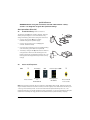
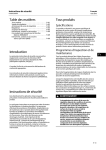
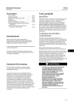
Start operations (S1 to S4)
S1:
Install the battery. Refer to Section 5.
The battery pack [a] (part number: IO620IS – Battery)
will be partly changed, it is recommended to fully
charge the battery pack before using the instrument:
•
Connect the charger [b] (part number:
IO620IS-Charger) to a power supply.
•
Connect the charger to the cradle [c] (part
number: IO620IS-Cradle).
•
Correctly insert the battery into the cradle (making
sure the battery pack label faces upwards).
•
The battery charger LED [d] indicates the different
charge states. When the LED shows green the
battery pack is fully charged and ready to use. The
battery pack takes approximately 8 hours to fully
charge.
S2:
[a]
[b]
[c]
[d]
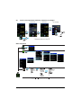
Power on/off sequence.
ON
M
First display
Press and hold
First display
for
DPI 620-IS CE
Wait
Normal output OFF
First display for
DPI 620-IS
M
Press and hold
for 3 seconds
Note: The instrument can also be put in stand-by mode (deep sleep mode). Stand-by mode can
only be initiated when the instrument is ON (i.e. normal output). Press and hold of the ON key for
1 sec to go into stand-by mode. To turn the instrument ON press the ON key for 1 sec. The
instrument will return to the last mode that it was configured. It is not recommended to keep the
instrument in stand-by for long periods of time (100hrs max) to preserve battery capacity.
[EN] English - K0461 issue 1
Quick Reference 5
S3:
Example change of function (Voltage to Current)
Task Settings
Channel Settings
3
4
2
1
TAP
Select Function
Current
Channel Settings
Task Settings
5
6
[EN] English - K0461 issue 1
7
8
Quick Reference 6
S4:
Touch-screen operations (maximise, minimise, set voltage)
Maximise
Set voltage
Minimise
3
*
1
2
4
*
1
* Alternative options for step M
TAP
Menu sequence
[EN] English - K0461 issue 1
Quick Reference 7
[EN] English - K0461 issue 1
Quick Reference 8
1
Overview
DPI 620-IS
MC 620-IS
PM620-IS
The intrinsically safe, advanced modular calibrator (AMC) is part of
a set of hand-held modules that can be quickly put together to
include a wide range of calibrator functions.
Advanced modular calibrator, DPI 620-IS: This is a
battery-powered instrument for electrical measure and source
operations and HART® communications; see table A1 (front cover).
It also supplies the power and user interface functions for all the
add-on modules. Use the touch-screen to display up to six
different parameters.
Pressure module carrier, MC 620-IS: Optional item. This attaches
to the DPI 620-IS calibrator to make a fully integrated pressure
indicator instrument. To measure and display pneumatic or
hydraulic pressures, up to two interchangeable pressure modules
can be used at a time. When not in use fit blanking device (part
number 191-369).
Pressure modules, PM 620-IS: Optional item. These modules
attach to the pressure module carrier (MC 620-IS) or to a pressure
station (PV 62x-IS) to give the DPI 620-IS calibrator the necessary
pressure measurement functionality. They are fully
interchangeable “plug and play” modules with no initial set-up or
user calibration.
Pressure stations, PV 62x-IS: Optional item. To make a fully
integrated pressure calibrator, attach the DPI 620-IS calibrator to
one of the three pressure stations. Refer to user manual - K0460.
PV 62x-IS
2
Standard
equipment
[EN] English - K0461 issue 1
These items are part of the standard equipment with the
DPI 620-IS calibrator:
•
DC power supply/battery charger unit
•
NiMH battery
•
Set of six electrical test leads
•
Safety and quick reference guide
•
CD with the user manual
•
DPI 620-IS CE version only: Plastic stylus (to tap small icons on
the screen)
Overview/Standard equipment
9
3
Safety
Before using the instrument, read and understand all the related
data. This includes: the applicable local safety procedures, the
user manual (K0460), and the instructions for the applicable
accessories/options/equipment.
Operators must be suitably qualified to use this intrinsically safe
equipment and comply with the conditions stated by the certifying
authorities.
To prevent an explosion or fire, only use the GE specified battery
(IO620IS-battery), battery cradle (IO620IS-cradle) and battery
charger (IO620IS-charger).
General
warnings
Electrical
warnings
10 Safety
WARNING
•
It is dangerous to ignore the specified limits for the
instrument or its related accessories. Do not use the
instrument or accessory if it is not in its normal condition.
Use the applicable protection and obey all safety
precautions.
•
Do not use the instrument in locations with explosive gas,
vapour or dust. There is a risk of an explosion.
•
To prevent electrical shocks or damage to the instrument,
do not connect more than 30V between the terminals, or
between the terminals and the ground (earth).
•
This instrument uses a Ni-MH (Nickel-Metal Hydride) battery
pack. To prevent an explosion or fire, do not short circuit,
do not disassemble, keep it safe from damage. For
operating conditions, see Table 1.
•
To prevent an explosion or fire, only use the GE specified
battery and battery charger.
•
To prevent battery leakage or heat generation, only use the
battery charger in the temperature range 0 to 40°C (32 to
104°F). For operating conditions, see Table 1.
•
To make sure the display shows the correct data, disconnect
the test leads before setting the power to on or change to
another measure or source function.
K0461 issue 1 - [EN] English
Pressure
warnings
Cautions
These warnings are applicable when using a pressure option
with the DPI 620-IS calibrator :
•
Some liquid and gas mixtures are dangerous. This includes
mixtures that occur because of contamination. Make sure
that the equipment is safe to use with the necessary media.
•
Pressurised gases and fluids are dangerous. Before
attaching or disconnecting pressure equipment, safely
release all the pressure.
•
To prevent a dangerous release of pressure, make sure that
all the related pipes, hoses and equipment have the correct
pressure rating, are safe to use and are correctly attached.
To prevent damage to the display, do not use sharp
objects on the touch-screen.
To prevent damage to the PM 620-IS module, only use
it within the specified pressure limit on the label.
Marks and
symbols on the
instrument
Complies with European
Union directives
Warning - refer to the
manual
Read the manual
USB port: Mini-type B
connector
Ground (Earth)
ON/OFF
Do not dispose of this product as household waste. Refer to
“Maintenance” (Section 5.5).
Do not dispose of the battery as household waste. Refer to
“Maintenance” (Section 5.5).
More marks and symbols are specified in the user manual (K0460 Druck DPI 620-IS Advanced Modular Calibrator)
[EN] English - K0461 issue 1
Safety 11
4
Parts
Refer to the figures on the front cover (A2, B1).
4.1 Key to figure A2 (DPI 620-IS calibrator)
A2
A2
1.
On or off button. Stand-by button. Refer to “Quick Reference”.
2.
CH1
Channel 1 connectors for: voltage (V); frequency (Hz);
resistance (Ω); resistance temperature detectors (RTD):
3W, 4W = 3-wire, 4-wire RTD input; switch operation; current (mA+,
mA-): COM = Common connector
3.
TC
Channel 1 connectors for thermocouples.
4.
CH2
Isolated channel 2 connector for:24V loop power supply (24Vo).
5.
CH2
Isolated channel 2 connectors for: voltage (V); current (mA+, mA-)
;switch operation.
6.
USB mini-type B connector for communication with a computer.
7.
Liquid crystal display (LCD): Colour display with touch-screen. To
make a selection, lightly tap on the applicable display area.
a.
8.
Battery indicator
b.
Date and time
CH1: Window for the channel 1 settings and values.
c.
Measure or source
indication
d.
Function
e.
Full scale (FS) range
f.
Function units
9.
Other windows: The number of windows you see on the display is
set by the number of task selections and external modules you are
working with (maximum: 6).
10.
Tap this button to set up the Task, set up the instrument
(Configure) and to access Help (?). Refer to “Quick Reference”.
Tap this button to maximise each of the available windows in
sequence. Refer to “Quick Reference”.
Pause (II) or Play (X): Tap (II) to hold (freeze) all the data on the
display. To release the display and continue, tap (X).
12 Parts
K0461 issue 1 - [EN] English
4.2 Key to figure B1 (MC 620-IS module carrier/PM620-IS module) - Optional item
B1
1.
Pressure connection (G1/8 or 1/8 NPT) to attach external pressure
equipment.
2.
Pressure and electrical connections for a pressure module
(PM620-IS). These are self-seal pressure connections.
3.
Two screws to attach the calibrator (DPI 620-IS).
4.
Electrical connections for the calibrator (DPI 620-IS).
5.
Pressure module (PM 620) with a pressure connection, reference
port (a) and a label. The label includes:
Pressure range. Example: 20 bar g (g: gauge; a: absolute);
serial number (S/N); manufacturer: name, address, website
5
Installation
Before starting:
•
Read and understand the “Safety” section.
•
Do not use damaged equipment.
Note: Use only original parts supplied by the manufacturer.
5.1 AMC battery
A3
Step
1.
See figure A3 (front cover).
Procedure
When the power is off, unscrew the five screws (a) and remove the
cover (b).
Turn the instrument over and collect the discharged battery. Do
not prise the battery out of the instrument case. Damage may
occur to the electrical gold spring pin contacts as a result.
2.
The battery can only be inserted in one orientation. The new
battery should be inserted with the label showing on the top face.
The chamfered edge should be face down and to the rear of the
pack. Do not force the battery into the case. Damage may occur
to the electrical gold spring pin contacts as a result.
3.
Re-fit the cover (b) and secure with the five screws (a) .
[EN] English - K0461 issue 1
Installation 13
5.2 Indicator
assembly
B2
Optional item (MC 620-IS/PM620-IS). See figure B2 (front cover).
Step
Procedure
1.
Align the two slots (a) on the calibrator with the two posts (b) on
the module carrier.
2.
When the posts are fully engaged in the slots, tighten the two
screws until they are hand-tight.
3.
Attach one or two PM620-IS modules with the correct range and
type.
4.
Tighten each one until it is hand-tight only.
5.3 Electrical
connections
See figure C1 to C4, and D1 (front cover).
5.4 External pressure
connections
See figure B1/E1 (front cover). Use an applicable method to seal
the external pressure connections, and then tighten to the
applicable torque.
5.5 Maintenance
Clean the case with a moist, lint-free cloth and a weak detergent.
Do not use solvents or abrasive materials.
Return the instrument to the manufacturer or an approved service
agent for all repairs. Refer to the user manual.
European Union
directives
14 Maintenance/Specification
Do not dispose of this product or its battery as household waste.
Use an approved organisation that collects and/or recycles waste
electrical and electronic equipment, and/or used batteries. This
will help keep to a minimum the effect these items have on the
environment and on human health. For more information, contact
one of these:
•
our customer service department:
(Contact us at www.gesensinginspection.com)
•
the local government office.
K0461 issue 1 - [EN] English
6
Specification
Table 1: General specification
Display
OLED: 480 x 272 pixels with touch-screen.
Operating temperature -10 to 40°C (14 to 104°F).
Storage
temperature
-20 to 70°C (-4 to 158°F).
Ingress Protection
IP65 (DPI 620-IS calibrator only).
Humidity
0 to 90% relative humidity (RH) non-condensing.
Shock/Vibration
Def Stan 66-31, 8.4 cat III.
EMC
Electromagnetic compatibility: BS EN 61326-1:2006.
Electrical safety
Electrical - BS EN 61010:2001.
Pressure safety
Pressure Equipment Directive - Class: Sound Engineering Practice
(SEP).
Approved
CE Marked.
Battery power
Ni-MH battery (GE Part number: IO620IS-BATTERY).
Capacity: 4000 mAh (typical); Nominal voltage: 3.6 V.
Charge temperature: 40°C (104°F) maximum.
Note: When the instrument senses the temperature is outside this
range, it stops charging.
Discharge temperature: -10 to 40°C (14 to 104°F).
Charge/discharge cycles: > 500 > 70% capacity.
15
K0461 issue 1 - [EN] English
16
K0461 issue 1 - [EN] English