1
.RQHODE6HUYLFH
0DQXDO
ZZZWKHUPRFRPNRQHODE
Manual version: I
Program version 6.0
Code: 48953054-4081
Version I
Preface
Preface-1
Preface
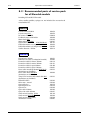
This manual gives technical information about Konelab 20, Konelab 30 and Konelab 60
analyzers and explains how to maintain and adjust them.
Audience
This manual is intended for personnel who service Konelab analyzers.
Scope
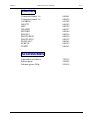
This Manual is divided into the following sections.
Warnings and Recommendations
Section 1
General
Section 2
Adjustments
Section 3
Cable Charts
Section 4
Different Parts of Konelab
Section 5
Maintenance
Section 6
Error Messages
Section 7
Boards
Section 8
Spare Parts & Consumables
Section 9
Installation Instructions
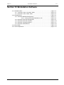
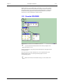
Section 10 Workstation Software
The CE mark attached on Konelab indicates the conformity with the EMC (electromagnetic
compatibility) directive 89/336/EC.
Information in this manual is subject to change without prior notice.
November 2, 2003
Thermo Clinical Labsystems
Tel: +358 9 802 766
Ratastie 2
Fax: +358 9 8027 6300
FIN-01620 VANTAA
www.thermo.com/konelab
48953054-4081
Konelab Service Manual
Preface-2
Konelab Service Manual
Preface
48953054-4081
Version I
November 2, 2003
Version I
Warnings and Recommendations
Warnings-1
Warnings and Recommendations
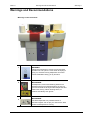
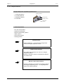
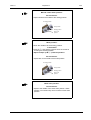
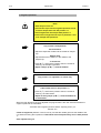
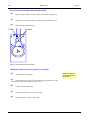
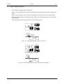
Warnings in the Instrument
2
3
1
1
4
6
7
5
1
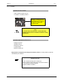
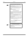
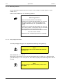
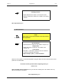
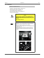
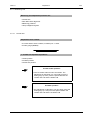
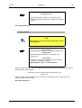
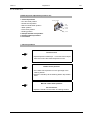
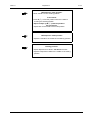
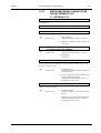
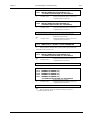
WARNING:
Follow the instructions to ensure correct and safe
operation.Do not open the cover when analysing is
going on, because moving dispensers and mixer
cause biohazard if hitting you by accident.
2
BIOHAZARD:
All dispensers, mixers and washing stations are
potential sources of infectious agents. Do not put
your hand inside the analyzer when dispensers and
mixers are moving. When cleaning them, be
cautious and always use gloves.
3
BIOHAZARD:
The Kusti dispenser is a potential source of
infectious agents. Do not put your hand to the area
where Kusti dispenser is moving.
November 2, 2003
48953054-4081
Konelab Service Manual
Warnings-2
Warnings and Recommendations
Version I
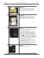
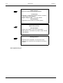
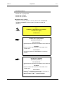
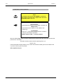
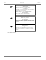
4
BIOHAZARD:
The cuvette waste box is a potential source of
infectious agents. Be cautious and always use
gloves and protective clothes when handling it.
5
BIOHAZARD:
The waste water canister is a potential source of
infectious agents. Be cautious and always use
gloves and protective clothes when handling it.
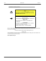
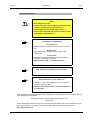
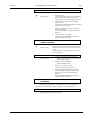
6
WARNING:
The low current switch, found in Konelab and KUSTI
models, does not turn power totally off. The low
current switch has two settings:
• The analyzer has power on, when the lo current
switch is ON (I), and at the same time the main
power switch, in the back of the analyzer, is on.
• When the low current switch is in the stand by
setting (O), only the boards of analyser and the
internal PC are power off. To turn the power totally
off, turn the main power switch, in the back of the
analyser, off. If you cannot reach the main power
switch, unplug the mains cable.
• If you take the mains cable off when the low
current switch is on, the back-up batteries of the
instrument are turned on.
You can boot the internal PC by turning the low
current switch in the stand by setting and waiting at
least one minute before turning it on.
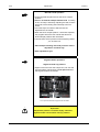
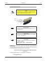
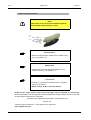
7
WARNING:
The lamp house can be hot.
Konelab Service Manual
48953054-4081
November 2, 2003
Version I
Warnings and Recommendations
Warnings-3
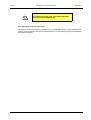
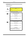
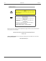
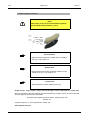
PINCH HAZARD!
Be careful with heavy parts of Konelab instrument
when servicing and adjusting it.
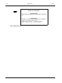
Recommendations for the Instrument
It is highly recommended that the workstation PC is equipped with UPS (= uninterruptible power
system) to avoid problems after power failure between PC's XP operating system and database
management software.
November 2, 2003
48953054-4081
Konelab Service Manual
Warnings-4
Konelab Service Manual
Warnings and Recommendations
48953054-4081
Version I
November 2, 2003
Version I
General
1-1
Section 1 General
1.1 Main Parts of the Analyzer ................................................................................... page 1-2
1.2 Samples ............................................................................................................... page 1-3
1.2.1 Konelab 20 ............................................................................................. page 1-4
1.2.2 Konelab 30 and 60 ................................................................................. page 1-4
1.3 Reagents ............................................................................................................. page 1-5
1.4 Cuvettes .............................................................................................................. page 1-5
1.5 Graphical User Interface....................................................................................... page 1-6
1.5.1 General Features ................................................................................... page 1-6
1.5.2 Special Keys on the Keyboard ............................................................... page 1-8
1.5.3 The Covers and the Leds in the analyzer ............................................... page 1-8
1.5.3.1 Konelab 60 and Konelab 30 ............................................ page 1-8
1.5.3.2 Konelab 20 ...................................................................... page 1-10
1.5.4 Main Window .......................................................................................... page 1-13
1.5.5 Brief Description of Windows .................................................................. page 1-15
1.6 Operation Principle .............................................................................................. page 1-17
1.6.1 Photometric Measurement ..................................................................... page 1-17
1.6.2 ISE Measurement ................................................................................... page 1-21
November 2, 2003
48953054-4081
Konelab Service Manual
1-2
General
Version I
Konelab, the selective chemistry analyzer for in vitro diagnostic purposes is an integrated system
solution for convenient and automatic testing of routine clinical chemistry tests, electrolytes and
special chemistries, such as specific proteins, TDM, DoA and toxicology tests.
The Konelab family consists of six models:
•
•
•
•
•
•
Konelab 60 which throughput is up to 600 photometric tests per hour.
Konelab 60i has the ISE unit, which raises the throughput up to 780 tests/hour.
Konelab 30 which throughput is up to 300 photometric tests per hour.
Konelab 30i has the ISE unit, which raises the throughput up to 480 tests/hour.
Konelab 20 which throughput is up to 200 photometric tests per hour.
Konelab 20i has the ISE unit, which raises the throughput up to 380 tests/hour.
The ISE unit combines the direct measurement of Na+, K+ and Cl- electrolytes with a sample
volume as low as 50 µl. Li+, Ca2+ and pH are offered as option for Konelab 60 and 30, Li+ for
Konelab 20.
Konelab 60 and 30 can be connected to the laboratory automation for direct sample dispensing
from the conveyor to the analyzer.
The instrument workstation has fully graphical user-interface software. The software provides
reliable control over the analyzing process and gives easy access to advanced functions.
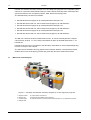
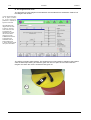
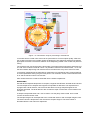
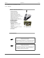
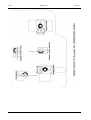
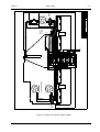
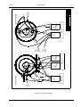
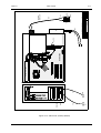
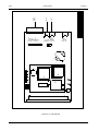
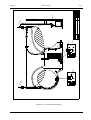
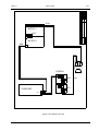
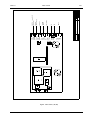
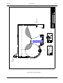
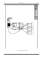
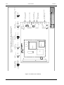
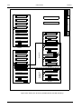
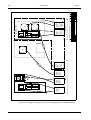
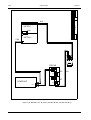
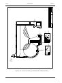
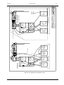
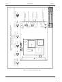
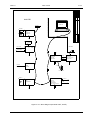
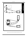
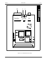
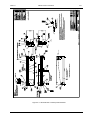
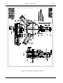
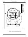
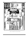
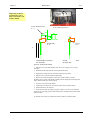
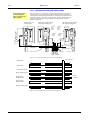
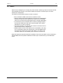
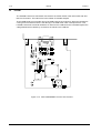
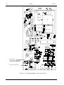
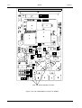
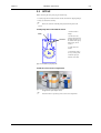
1.1
Main Parts of the Analyzer
*
%
&
$
'
(
)
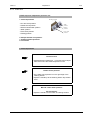
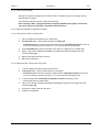
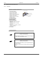
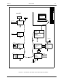
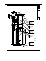
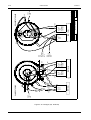
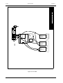
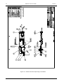
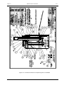
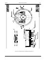
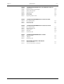
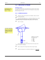
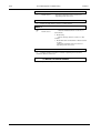
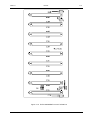
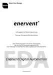
Figure 1-1 Konelab, the selective chemistry analyzer for in vitro diagnostic purposes
A. Segment loader
E. Cuvette waste compartment
B. Sample disk
F. Wastewater and distilled water containers
C. Cuvette loader
G. Optional interface for the automated sample transport line, so called KUSTI module
D. Reagent disk
Konelab Service Manual
48953054-4081
November 2, 2003
Version I
General
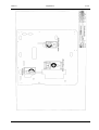
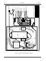
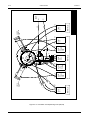
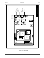
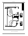
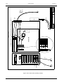
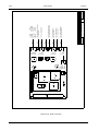
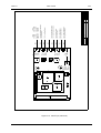
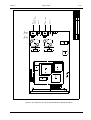
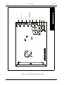
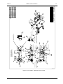
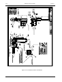
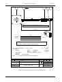
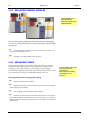
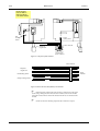
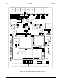
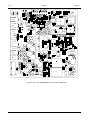
%
1-3
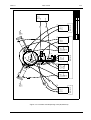
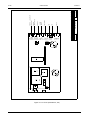
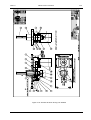
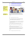
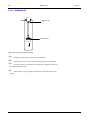
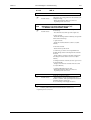
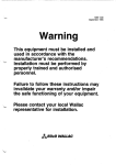
A. Segment/ STAT sample loader
B. Reagent disk
C. Cuvette loader
D. Cuvette waste compartment
&
E. Wastewater and distilled water containers
$
'
(
Figure 1-2 Konelab 20, the selective chemistry analyzer for in vitro diagnostic purposes
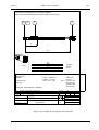
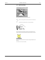
1.2
Samples
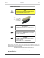
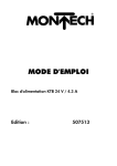
Samples are inserted in a 14 positions sample segment. Continuous processing is made possible
by the use of independent bar-coded sample segments, which the user can insert or remove
during analysis to enable loading and unloading of samples. After loading the segment, samples
are immediately identified by direct barcode reading and cup type recognition. Six segments can
be in the sample disk at the same time. For the STAT samples there are dedicated positions
between the segments, 5 positions in Konelab 20 and 6 positions in Konelab 30 and 60.
Standard segment holds 5 and 7 ml primary tubes as well as 0.5 and 2 ml sample cups. A special
segment for 10 ml tubes is available. The data can be given and results reported according to a
patient or according to a sample. In addition the data can be entered during analysis.
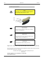
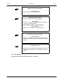
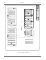
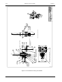
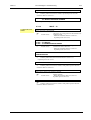
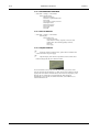
Figure 1-3 A sample segment
November 2, 2003
48953054-4081
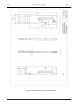
Figure 1-4 A KUSTI segment
available to Konelab 30 and 60
Konelab Service Manual
1-4
General
Version I
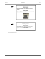
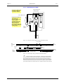
1.2.1 Konelab 20
Calibrators and controls are introduced as normal samples into a segment or into STAT positions.
One STAT sample position is reserved for the ISE prime sample.
67$7VDPSOHV
3DWLHQWFDOLEUDWRUDQGFRQWURO
VDPSOHV
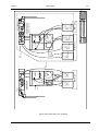
Figure 1-5 The sample disk of Konelab 20
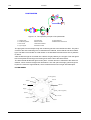
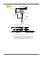
1.2.2 Konelab 30 and 60
Calibrator, control and ISE prime samples have 40 fixed cooled positions in the middle of the
sample disk. The positions are marked from S0 to S19, from C1 to C19 and ISE PRIME.
Calibrators and controls can also be without fixed positions. In that case they are introduced as
normal samples into a segment or into STAT positions.
In case automated sample transport is used, the analyzer is equipped with the optional KUSTI
module and samples are dispensed to a disposable 92 positions segment. Further analysis of the
sample from the KUSTI segment is continued in a normal manner according to the analysis
requested. Simultaneous manual sample operation, e.g. for STAT and special samples, is
possible.
&DOLEUDWRUDQGFRQWUROVDPSOHV
67$7VDPSOHV
3DWLHQWVDPSOHV
Figure 1-6 The sample disk of Konelab 30 and 60
Konelab Service Manual
48953054-4081
November 2, 2003
Version I
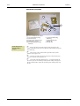
1.3
General
1-5
Reagents
The analyzer has a cooled reagent disk for 60 ml vessels, 20 ml and 10 ml bottles. The reagent
disk of Konelab 30 and 60 includes integrated barcode reader, in Konelab 20 the barcode reader
for reagents is external. The data for the reagents without a barcode has to be entered in the
REAGENT DEFINITION window. Dilution as well as buffer solutions are placed in the reagent
disk.
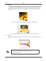
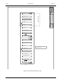
Figure 1-7 Reagent vials and the 35-position reagent disk in the Konelab 20.
Figure 1-8 Reagent vials and the 45-position reagent disk in the Konelab 30 and 60.
1.4
Cuvettes
Samples and reagents are dispensed into a cell of multicell cuvette. One multicell cuvette has 12
cells.
Figure 1-9 A multicell cuvette
WARNING!
The quality of results is guaranteed only with new cuvettes.
Do not reuse the cuvettes.
November 2, 2003
48953054-4081
Konelab Service Manual
1-6
1.5
General
Version I
Graphical User Interface
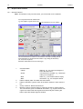
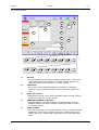
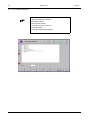
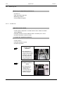
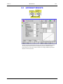
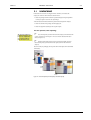
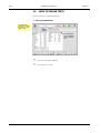
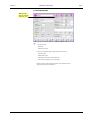
1.5.1 General Features
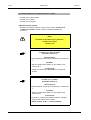
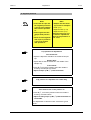
Note: This window is only for instructions, you cannot find it in the software.
<RXFDQRSHQWKHOLVWRIWKHZLQGRZLWHPV
HJWHVWVVDPSOHVUHDJHQWVVDPHDV)
7KHVHEXWWRQVDUHLQHYHU\ZLQGRZ
$OODFWLYHIXQFWLRQVKDYHDEODFNWH[W7KHIXQFWLRQLVDFWLYDWHGE\FOLFNLQJZLWKWKH
PRXVHOHIWEXWWRQRYHUWKHEXWWRQLQWKHZLQGRZRUE\SUHVVLQJWKHIXQFWLRQNH\
))RQWKHNH\ERDUG
)XQFWLRQVZKLFKFDQQRWEHXVHGDUHVKRZQJUH\
1
2
3
4
5
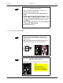
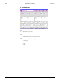
Coloured labels:
• Yellow:
Warning, e.g., the volume of reagent is
below the alarm limit.
• Green:
User actions are needed, e.g., results are
waiting for acceptance.
• Red:
Alarm, e.g., the cuvette loader is empty.
• Blue:
Information, e.g., the analyzer's status.
Fields to display data: This data cannot be edited.
Fields to edit data: Type the value to the field or select the value from the
list.
Group of buttons: Select several items.
Buttons to press: Click the button to open the window for further actions.
The coloured line gives an additional information, e.g.,segment button with
a green line means that the segment has been analyzed. Clicking the
button opens the sample segment window.
Konelab Service Manual
48953054-4081
November 2, 2003
Version I
General
1-7
Moving in the window from the field to another:
To move from the field to another :
-
click the left mouse button:
-
or press enter
-
or tabulator
To move backwards press:
-
shift and tabulator at the same time
Selection from the list and from the table:
Clicking the left mouse button or moving the cursor with the arrow keys on the keyboard and
pressing Space bar selects an item from the list and from the table.
When you select the same list/ table item again, the item becomes unselected.
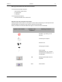
Symbol in the window
Symbol on the
keyboard
Meaning / Function:
Function, e.g. Saving, is not
allowed.
Activating the analyzer.
Selection list.
Changing the window.
!
STAT sample
Undefined value, e.g. a limit in
test parameters marked with * is
not checked.
*
November 2, 2003
F9
Sample/ patient data and test
requests.
F10
Tests results
48953054-4081
Konelab Service Manual
1-8
General
Symbol in the window
Version I
Symbol on the
keyboard
Meaning / Function:
F11
The status of all reagents in the
reagent disk.
F12
The analyzer's status.
1.5.2 Special Keys on the Keyboard
Start
Press START to begin analysis. Note that you must be on the
Main window to get it working.
Stop
Press STOP to stop all analyzing. To restart analyzing, press
START.
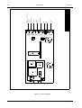
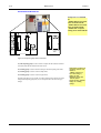
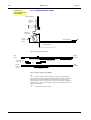
1.5.3 The Covers and the Leds in the analyzer
1.5.3.1 Konelab 60 and Konelab 30
A. The segment insert cover:
• When the green LED (LA) is on, the user is allowed to open the cover.
• When the red LED is on, the user must NOT open the cover because all six segment positions
are reserved or the analyzer is transporting the segment between the segment loader and the
sample disk.
B. The STAT insert cover:
• The LED (LB) red light starts to blink when the user opens the STAT insert cover. The
analyzer turns a free position to the STAT insert position. AFTER the LED stops blinking and
remains green, the user can insert the STAT sample.
Konelab Service Manual
48953054-4081
November 2, 2003
Version I
General
&DO&WUO
VDPSOHGLVN
FRYHU
1-9
/$
%
$
/%
C. The cuvette loader:
• When the green LED (LC) is on, the user is allowed to open the cuvette loader cover.
• When the red LED is on, the user must NOT open the cover because the analyzer is
transporting the cuvettes between the cuvette loader and the cuvette storage or the cuvette
storage is full.
&
/&
D. The reagent insert cover:
The LED (LD) red light starts to blink when the user opens the reagent insert cover. The analyzer
turns a free position to the reagent insert position. AFTER the LED stops blinking and remains
green, the user can insert the reagent.
'
5HDJHQWGLVN
FRYHU
/'
November 2, 2003
48953054-4081
Konelab Service Manual
1-10
General
Version I
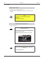
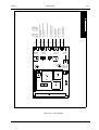
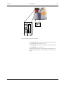
1.5.3.2 Konelab 20
E. The segment/ Stat insert cover:
Inserting the segment
The procedure to insert segment into Konelab 20 must be started from the workstation,
select F2 either in the Sample/Patient entry window or in the Segment window.
The LED (LE) starts to blink red light. The analyzer turns a free position to segment/ STAT insert
position. After the LED stops blinking and remains green the user can open the cover and insert
the segment. When the cover is closed the LED goes out.
(
/(
Konelab Service Manual
48953054-4081
November 2, 2003
Version I
General
1-11
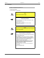
Inserting the STAT sample
Select F5, Insert stat sample in the Sample/Patient entry window.
The LED (LE) starts to blink red light. The analyzer turns a free position to segment/ STAT insert
position. After the LED stops blinking and remains green the user can open the cover and insert
the STAT sample. When the cover is closed the LED goes out.
F. The cuvette loader:
• When the green LED (LF) is on the user is allowed to open the cuvette loader cover.
• When the red LED is on the user must NOT open the cover because the analyzer is
transporting the cuvettes between the cuvette loader and the cuvette storage or the cuvette
storage is full.
)
/)
November 2, 2003
48953054-4081
Konelab Service Manual
1-12
General
Version I
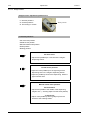
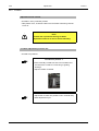
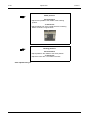
G. The reagent insert cover:
The procedure to insert reagent into Konelab 20 must be started from workstation. Select F2 in
the Reagent disk window.
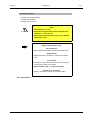
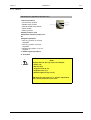
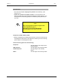
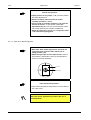
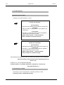
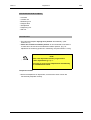
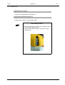
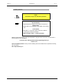
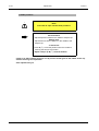
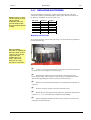
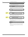
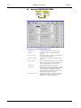
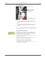
If user levels have been
set on (refer to section
3.7 in Ref. manual) the
password is required to
login the instrument
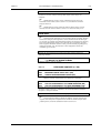
Old calibrations and
reagent vials are seen
in Start up. The user
must insert new vials
and request new
calibrations or accept
the old ones before
continuing.To look
at Maintenance actions
is reminded if the
workstation has not
been booted during
a week. Booting makes
the system work faster.
The LED (LG) starts to blink red light. The analyzer turns a free position to reagent insert position.
After the LED stops blinking and remains green the user can open the cover and insert the
reagent vial. When the cover is closed the LED goes out.
*
/*
Konelab Service Manual
48953054-4081
November 2, 2003
Version I
General
1-13
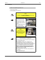
1.5.4 Main Window
(
%
)
/
0
'
&
*
$
+
1
-
,
.
A
B
C
D
E
November 2, 2003
)
4&
UHVXOWV
)
,QVWU
DFWLRQV
)
0DQDJH
PHQW
)
3URILOH
GHILQLWLRQ
)
7HVW
GHILQLWLRQ
)
5HDJHQW
GHILQLWLRQ
)
&DO&WUO
GHILQLWLRQ
)
&RQILJ
)
5HVXOW
DUFKLYH
)
3HQGLQJ
UHTXHVWV
)
%DWFK
HQWU\
)
([WHUQDO
UHVXOWV
)
6HQGHU
GHILQLWLRQ
)
5HIFODVV
GHILQLWLRQ
)
PRUH
)
PRUH
STATUS:
• The analyzer's status (e.g. start up needed, analyzing etc.) is seen and if
cuvettes are missing (for example), a red label Cuvettes appears. For
further information refer to section 1.3.1 in Ref. manual.
STATISTICS:
• The number of all unanalyzed requests, the number of unanalyzed
requests in the sample disk, and the number of analyzed requests are
seen.
TESTS TO ACCEPT:
• Calibrations and tests, which have unaccepted results, are seen. Refer to
sections 3.4.2 and 3.3.1 in Ref. manual.
SAMPLES/ PATIENTS TO ACCEPT:
• Samples/ Patients, who have analyzed, unaccepted results are seen.
Samples/ Patients with STAT requests are listed first. Refer to section
3.3.2 in Ref. manual.
OPEN COVERS:
• The name of the open cover is listed. When the cover is closed, the name
disappears. The covers are reagent insert cover, segment insert cover,
STAT insert cover, cuvette loader, reagent disk cover, and sample disk
cover.
48953054-4081
Konelab Service Manual
1-14
General
F
G
H
I
J
K
L
M
N
Version I
SHORT SAMPLES:
• List of short and old samples is seen. Refer to section 3.2.2 in Ref. manual.
REAGENTS BELOW ALARM:
• List of reagents with volume below the defined alarm limit is seen. Refer to
section 3.1.2 in Ref. manual.
SHORT REAGENTS:
• List of short reagents is seen. Refer to section 3.1.2 in Ref. Manual.
SHORT CALIBRATORS AND CONTROLS:
• List of short and old calibrators and controls is seen. Refer to section 3.4.1
in Ref. manual.
INVALID TESTS:
• Invalid tests are listed; e.g., calibration, reagent or antigen excess sample
is missing or the analyzer is unable to do the test because the checking of
test's parameters is needed.
MESSAGES:
• All messages are seen in the MESSAGES window with an explanation, an
identification number, and time. Refer to section 8.2.
SAMPLE DISK:
• The status of all segments and patient samples is seen. Refer to section
3.2.8 in Ref. manual.
SEGMENTS:
• Segments on board are seen. Segment identification is in a button. Refer to
section 3.2.7 in Ref. manual.
The segment's status is seen beside the button:
• In process: The segment is under analyzing.
• Ready (the green line in the button): The segment has been analyzed.
• Not started (a yellow line in the button): The segment is in the sample disk
but the barcode is not read yet.
• In loader: The segment is in the loader and can be taken away.
• Check data (a red line in the button): There is unrecognised sample in the
segment. Refer to section 3.2.7.1.1 in Ref. manual.
• Discarded segment (a red line in the button): The analyzer has been unable
to read segment's barcode. Click the button or press F9 and further F8/F5
keys on the keyboard; with F3, remove the segment and check the
barcode.
STAT SAMPLES:
• Samples on the STAT positions are seen. Sample identification is in a button. The green line in the sample button means that the sample is ready to
accept or report. The red line means short sample. Refer to section 3.2.4 in
Ref. manual.
To open the needed window for further actions:
Click the name on the list (C, D, F, G, H, I and K).
Click the button (L, M and N).
- or Select the name from the list (C, D, F, G, H, I and K) and press the appropriate key on the
keyboard, e.g. F10 to open the TEST RESULTS window. Press the appropriate keys on the
keyboard (L, M and N), e.g. F9 and further F8/F6 keys to open the SAMPLE SEGMENT window.
Konelab Service Manual
48953054-4081
November 2, 2003
Version I
General
1-15
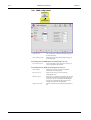
1.5.5 Brief Description of Windows
Batch entry
Functions to give test requests for a batch of samples. Refer to section 3.2.2.3 in
Ref. manual.
Configuration
In the Configuration window, the user can see e.g., the installed wavelengths. In
addition the user can e.g., define the criterion for data entering: sample or patient,
change the default sample type used in Sample/ Patient entry, define the printing
type: manual or automatic and connect the ISE unit on and off. Refer to section 3.8
in Ref. manual.
LIMS
configuration
The used laboratory information management protocol is defined. Refer to section
3.8.1 in Ref. manual.
Management
Functions to stop the instrument immediately and to clear the daily files and
simultaneously to save accepted QC results to the cumulative data. Refer to section
3.6 in Ref. manual.
User
management
Functions to set user levels on and change passwords. Refer to section 3.7 in Ref.
manual.
Restrictions
Functions to determine different user levels. Refer to section 4.10 in Ref. manual.
Messages
Detailed information from the messages is seen. Refer to section 8.2.
Profile definition
Functions to define the profiles. Refer to section 4.7 in Ref. manual.
Reagent
definition
Functions to give the reagent data. Refer to section 3.1.3 in Ref. manual.
Reagent disk
The status of all reagents in the reagent disk is seen in this window.
The user has access to the REAGENT DISK window from every window. Refer to
section 3.1.1 in Ref. manual
Reference class
definition
Functions to define reference classes. Refer to section 4.8 in Ref. manual.
Reports
Functions to report the results manually. Refer to section 3.5 in Ref. manual.
LIMS connection
Functions to manually ask requests or send results online. Refer to section 3.5.1 in
Ref. manual.
Sample disk
The status of all segments and patient samples on board is seen in this window.
Refer to section 3.2.8 in Ref. manual.
Sample/ Patient
entry
Functions to give sample/patient data and test requests. The criterion for the data
entering (sample or patient) is defined in the Configuration window.
The user has access to the SAMPLE/ PATIENT ENTRY window from every
window. Refer to section 3.2.2 in Ref. manual.
Sample list
A brief preview of all samples is seen in this window. Refer to section 3.2.9 in Ref.
manual.
Sample/ Patient
results
Functions to see the results of samples/ patients. The unaccepted results can be
accepted, rejected, or rerun. Refer to section 3.3.2 in Ref. manual.
Sample segment
The status of sample segment with all 14 positions is seen. Refer to section 3.2.7 in
Ref.manual.
Pending
requests
Pending requests and the time estimation for analyzing them are seen in this
window. Refer to section 3.2.10 in Ref. manual.
Sender definition
Functions to define the sender data, which is seen in Sample/ Patient entry and in
reports. Refer to section 4.9 in Ref. manual.
Calibrator &
Control definition
Functions to define calibrators and controls and to give the test values. Refer to
section 4.6 in Ref. manual.
Calibration
parameters
Functions to define the test calibration parameters. Refer to section 4.4 in Ref.
manual.
Calibration
results
The status of the test calibration is seen. Calibration can be accepted and
compared to the previous one. Every calibration request can be rejected and rerun.
Refer to section 3.4.2 in Ref. manual.
Calibration/ QC
selection
The list of tests in the order of the calibration status and the status of calibrators is
seen.
The user can calibrate the test and ask the Manual QC for the test. The status of
controls is seen. Refer to section 3.4.1 in Ref. manual.
November 2, 2003
48953054-4081
Konelab Service Manual
1-16
General
Version I
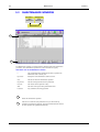
Quality control
results
Cumulative data and quality control results are seen on the lists or graphically.
Refer to section 3.4.3 in Ref. manual.
Results by
controls
Daily quality control results by controls are seen. Refer to section 3.4.4 in Ref.
manual.
Quality control
parameters
Functions to define tests' quality control parameters for manual qc and routine qc.
Refer to section 4.5 in Ref. manual.
Test definition
Functions to define tests. Tests' general parameters are given in this window. Refer
to section 4.1 in Ref. manual.
Test flow
Functions to define the test flow i.e. the parameters for reagent and sample
dispensings, for dilution, incubation and measurement. Additional mixing can also
be defined. Refer to section 4.2 in Ref. manual.
Electrodes
Function to define which electrodes is used. Refer to section 4.3 in Ref. manual.
Test results
Functions to see the results of the tests. Unaccepted results can be accepted,
rejected or rerun.
The user has access to the TEST RESULTS window from every window. Refer to
section 3.3.1 in Ref. manual.
External results
Functions to enter results for tests analyzed by other instruments to provide fully
collated patient reports. Refer to section 3.2.6.1in Ref. manual.
Result archive
Result archive includes sample and control results. Refer to section 3.9 in Ref.
manual.
Calibration
archive
Calibration archive includes old, accepted calibrations. Refer to section 3.9.1 in Ref.
manual.
Reagent lot
archive
Reagent lot archive includes information of used reagent lots. Refer to section 3.9.2
in Ref. manual.
Statistics
Both daily and cumulative number of accepted and rejected requests of samples,
calibrators and controls are seen test by test. Refer to section 3.10 in Ref. manual.
Report formats
Functions to format the patient, sample, or test report. Refer to section 3.11 in Ref.
manual.
Instrument
actions
Functions for the user service actions, e.g. to order water blank and ISE prime and
to remove cuvettes. Adjustment and test programs for Service Engineers. Refer to
section 3.12 in Ref. manual.
Water blank
Functions to check water blank measurements wavelength by wavelength. Refer to
section 3.13 in Ref. manual.
Maintenance
Maintenance checking table. The user is reminded to perform tasks after the given
time period. Refer to section 6.1 in Ref. manual.
Accuracy results
After the preventive maintenance done once per year, it is recommended to
perform accuracy measurements to check the condition of instrument. Results of
these measurements are seen in this window. Refer to section 6.4 in Ref. manual.
Accuracy factors
Accuracy measurements are done with the accuracy solution kit. Authority
measures values of these solutions. Lot dependant factors, affecting accuracy
result calculations, are given in this window. Refer to section 6.4.1 in Ref. manual.
Konelab Service Manual
48953054-4081
November 2, 2003
Version I
1.6
General
1-17
Operation Principle
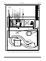
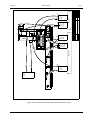
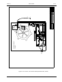
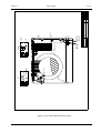
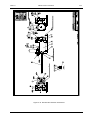
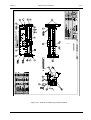
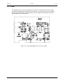
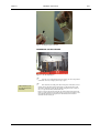
1.6.1 Photometric Measurement
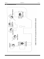
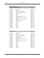
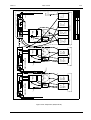
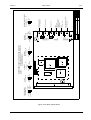
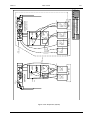
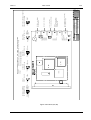
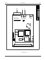
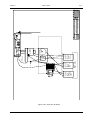
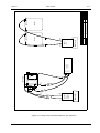
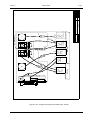
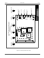
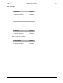
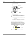
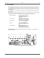
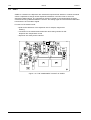
Figure 1-10 Photometric analysis proceeding in Konelab 60.
Multicell cuvettes are transported in the Konelab by precisely controlled cuvette arms. The arm
takes a cuvette from the loader and places it into a free slot in the incubator. When the incubator
rotates in Konelab 60 the cuvette is first moved to the photometer to check its optical quality and
after that to the dispensing positions where the dispensing arms dispense sample and reagents
appropriate to the test. The mixer in both dispensing positions performs efficient mixing.
November 2, 2003
48953054-4081
Konelab Service Manual
1-18
General
Version I
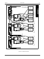
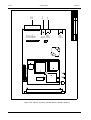
3+2720(7(5
237,21
,6(02'8/(
,6(',63(16(5
$ % !"!&
!"
#
,1&8%$725
!"
6$03/(
75$163257
/,1(
.21(/$%
6$03/(
75$163257
,17(5)$&(
%8))(5
',63(16(5
6$03/($1'
5($*(17
',63(16(5
6$03/(',6.
%XI I HU
VHJPHQW
!"
&89(77(/2$'(5
&89(77(6
5($*(17', 6.
&89(77(6725$*(
&89(77(6
&89(77( 81, 7
%$5&2'(
5($'(5
%$5 &2'( 5($'(5
0DQXDO
VDPSOHORDGLQJ
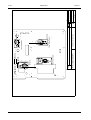
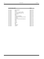
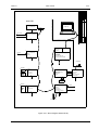
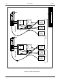
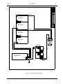
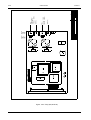
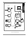
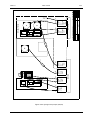
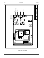
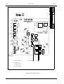
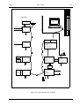
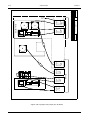
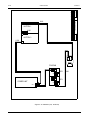
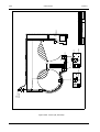
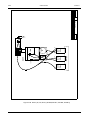
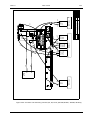
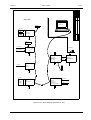
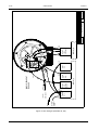
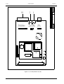
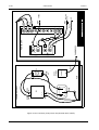
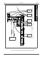
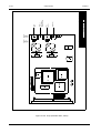
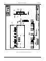
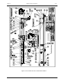
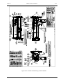
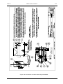
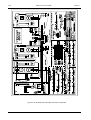
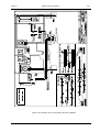
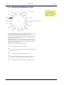
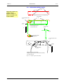
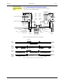
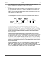
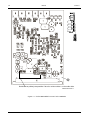
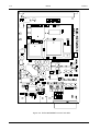
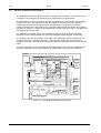
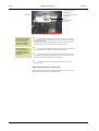
Figure 1-11 Photometric analysis proceeding in Konelab 30.
In Konelab 30 the cuvette is also first moved to the photometer to check its optical quality. After
that the cuvette is placed in the incubator where the dispensing arm dispenses sample and
reagents appropriate to the test. The mixer performs efficient mixing.
The cuvette is then moved through the photometer. The photometer measures the absorbance of
one cell of the multicell cuvette at a time. It is possible to make a fixed measurement, i.e. so that
the time between dispensing and measurement is the same with every cell of a test's cuvette.
In the kinetic measurement the absorbance measurement is repeated as many times as defined
in the test parameters during the given time period. The maximum number of the measurements
is 12 and the maximum time is 20 minutes.
After measurement the cuvette is discarded into the waste compartment.
Konelab Service Manual
48953054-4081
November 2, 2003
Version I
General
1-19
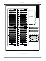
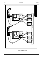
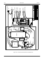
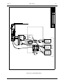
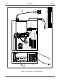
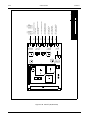
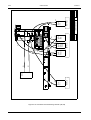
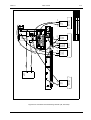
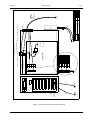
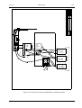
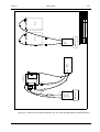
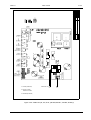
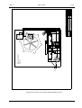
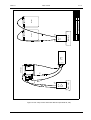
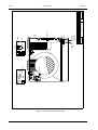
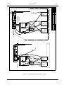
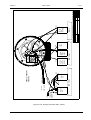
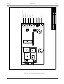
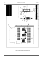
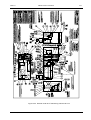
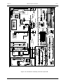
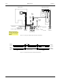
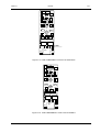
Figure 1-12 Photometric analysis proceeding in Konelab 20.
In Konelab 20 the cuvette is first moved to the photometer to check its optical quality. After that
the cuvette is placed in the incubator where the dispensing arm dispenses sample and reagents
appropriate to the test. The efficient vibration of the dispensing needle in the cuvette cell performs
mixing.
The cuvette is then moved through the photometer. The photometer measures the absorbance of
one cell of the multicell cuvette at a time. It is possible to make a fixed measurement, i.e. so that
the time between dispensing and measurement is the same with every cell of a test's cuvette.
In the kinetic measurement the absorbance measurement is repeated as many times as defined
in the test parameters during the given time period. The maximum number of the measurements
is 12 and the maximum time is 20 minutes.
After measurement the cuvette is discarded into the waste compartment.
DISPENSING
Konelab 60 has separate dispensers for samples, reagents and ISE tests. Konelab 30 and 20 has
common dispenser for samples and reagents but separate for ISE tests. The dispensers are
equipped with a level detector, which ensures that there is enough sample/reagent for the
analyzes requested. The level detector also controls the depth of immersion of the needle in the
sample cup.
A sample is dispensed either into a new cuvette or into the partly used cuvette. One cuvette
consists of twelve reaction cells.
The sample/ reagent can be dispensed to the cuvette with water or with a sample/ reagent extra.
The water volume is dispensed to the cell with the sample/ reagent. The extra volume is
discarded after the real volume is dispensed.
November 2, 2003
48953054-4081
Konelab Service Manual
1-20
General
Version I
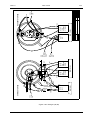
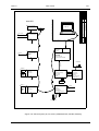
3+2720(7(5
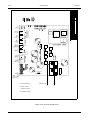
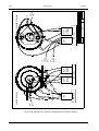
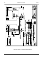
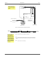
Figure 1-13 The operation principle of the photometer.
1. Halogen lamp
5. Quartz fibre
2. Condensing lenses
6. Beam divider
3. Filter wheel
7. Reference detector
4. Light chopper
8. Multicell cuvette
9. Signal detector
10.Measurement electronics
The light goes from the lamp through the condensing lenses to the interference filter. The plane
surface of the first condensing lens is coated with the material, which reflects heat and infrared
light. The filters are mounted on a filter wheel. In the standard instrument there are 15 positions
for filters.
After the filter the light is converted into a stream of light pulses by the chopper. Then the light is
led via the quartz fibre through the focusing lens and the slit to the beam divider.
The beam divider divides the light into two parts. A certain amount is reflected to the reference
detector, which monitors the light level fluctuations. The main part of the light goes through the
liquid in the cell to the signal detector, which measures the amount of light after absorption.
FILTER WHEEL
QPRSWLRQ
QP
QP
QP
%ODFN
QP
(PSW\
QPRSWLRQ
QP
QP
QP
QP
QP
Konelab Service Manual
QP
QP
48953054-4081
November 2, 2003
Version I
General
1-21
1.6.2 ISE Measurement
The Konelab measures:
•
•
•
•
Na, K and Cl in serum and plasma,
Na and K in urine,
Li, which is offered as an option, in serum and plasma.
Ca and pH in Konelab 60 and 30, which are offered as an option, in serum and plasma.
The measurement is done with the direct ISE technique. The measured sample activity is
compared to the activity of calibrators, which are adjusted to mimic activity normally found in
serum samples.
The electrode block is comprised of the measurement electrodes and the reference electrode.
The potentials produced at each membrane are measured once every second.
One dispensing arm, one pump and one 500 *l syringe are provided for the ISE measurement in
Konelab 60 and 30. In Konelab 20 one dispensing arm and FMI pump perform the ISE
measurement. A sample is aspirated through the needle from the sample cup. The sample is
moved to the electrode block where the measurement takes place.
Sample measurement is followed by ISE Calibrator solution 1 measurement. The ISE dispensing
pump transfers ISE Calibrator solution 1 from the bag to the block. At the same time the sample is
discarded. After the measurement ISE Calibrator solution 1 is pumped through the needle to the
waste.
The tubes and the measurement channel of the ion selective electrode block are washed with the
Washing Solution. The solution is dispensed via the dispensing arm into the block. From there it
is pushed by the ISE washing pump into the wastewater container. The washing procedure is
done during the STAND BY function.
MEASUREMENT PRINCIPLE
Each ion-selective electrode has an electrode -specific membrane. The membrane will attract the
desired ion to the membrane phase when the sample solution comes into contact with it. The
potential of each ion-selective electrode is measured against the reference electrode. The
potential difference is developed at the electrode membrane. This potential (in mV) is read and
amplified sequentially. It should reach the 'steady state' stage within a given time interval. If the
measurement does not stabilise in an allowed time the measurement is repeated once. In case of
repeated instability an error message is given.
November 2, 2003
48953054-4081
Konelab Service Manual
1-22
Konelab Service Manual
General
48953054-4081
Version I
November 2, 2003
Version I
Adjustments
2-1
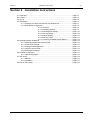
Section 2 Adjustments
2.1 Adjustments of Konelab 60 ....................................................................... page 2-3
2.1.1 General ...................................................................................... page 2-3
2.1.2 How to Start Adjusting ? ............................................................ page 2-4
2.1.3 Cuvette Unit ............................................................................... page 2-6
2.1.4 Incubator .................................................................................... page 2-11
2.1.5 Reagent Unit .............................................................................. page 2-13
2.1.5.1 Cuvette Arm .................................................................... page 2-13
2.1.5.2 Reagent Disk ................................................................... page 2-14
2.1.5.3 Reagent Dispenser ......................................................... page 2-15
2.1.5.4 Reagent Mixer ................................................................. page 2-20
2.1.6 Sample Unit ............................................................................... page 2-23
2.1.6.1 Cuvette Arm .................................................................... page 2-23
2.1.6.2 Sample Disk .................................................................... page 2-24
2.1.6.3 Sample Dispenser
page 2-28
2.1.6.4 Sample Mixer .................................................................. page 2-36
2.1.7 Measuring Unit .......................................................................... page 2-39
2.1.7.1 Cuvette Arm .................................................................... page 2-39
2.1.7.2 Filter Disk / Beam Alignment ........................................... page 2-41
2.1.7.3 Measuring Positions ........................................................ page 2-42
2.1.7.4 Lamp Voltages and Gains ............................................... page 2-42
2.1.8 ISE Unit ..................................................................................... page 2-43
2.1.9 KUSTI Unit ................................................................................. page 2-49
2.1.10 Syringe Zero Position .............................................................. page 2-53
2.1.11 Saving and Restoring Adjustment Values ............................... page 2-53
2.1.11.1 Saving Adj. Values to Floppy Disk ............ page 2-53
2.1.11.2 Restoring Adj. Values from Floppy Disk .... page 2-53
2.2 Adjustments of Konelab 30 ...................................................................... page 2-55
2.2.1 General ...................................................................................... page 2-55
2.2.2 How to Start Adjusting ? ............................................................ page 2-56
2.2.3 Incubator .................................................................................... page 2-58
2.2.4 Cuvette Unit ............................................................................... page 2-59
2.2.5 Reagent Disk ............................................................................. page 2-60
2.2.6 Sample Disk .............................................................................. page 2-61
2.2.7 Measuring Unit .......................................................................... page 2-65
2.2.7.1 Cuvette Arm .................................................................... page 2-65
2.2.7.2 Filter Disk / Beam Alignment ........................................... page 2-66
2.2.7.3 Measuring Positions ........................................................ page 2-67
2.2.7.4 Lamp Voltages and Gains ................................................ page 2-67
2.2.8 Dispensing Unit ......................................................................... page 2-68
2.2.8.1 Dispenser ......................................................................... page 2-68
2.2.8.2 Mixer ............................................................................... page 2-78
2.2.9 ISE Unit ..................................................................................... page 2-81
2.2.10 KUSTI Unit ............................................................................... page 2-87
2.2.11 Syringe Zero Position .............................................................. page 2-91
2.2.12 Saving and Restoring Adjustment Values ............................... page 2-91
2.2.12.1 Saving Adj. Values to Floppy Disk ............ page 2-91
2.2.12.2 Restoring Adj. Values from Floppy Disk .... page 2-91
November 2, 2003
48953054-4081
Konelab Service Manual
2-2
Adjustments
Version I
2.3 Adjustments of Konelab 20 .................................................................................. page 2-93
2.3.1 General .................................................................................................. page 2-93
2.3.2 How to Start Adjusting ? ........................................................................ page 2-94
2.3.3 Incubator ................................................................................................ page 2-96
2.3.4 Cuvette Unit ........................................................................................... page 2-97
2.3.5 Measuring Unit ...................................................................................... page 2-98
2.3.5.1 Cuvette Arm .................................................................... page 2-98
2.3.5.2Filter Disk / Beam Alignment ............................................. page 2-99
2.3.5.3 Measuring Positions ........................................................ page 2-100
2.3.5.4 Lamp Voltages and Gains ............................................... page 2-100
2.3.6 Reagent Disk ......................................................................................... page 2-101
2.3.7 Sample Disk .......................................................................................... page 2-102
2.3.8 Dispensing Unit of Konelab 20, 20i ....................................................... page 2-104
2.3.8.1 Dispenser ....................................................................... page 2-104
2.3.9 Dispensing Unit of Konelab 20XT, 20XTi ............................................... page 2-111
2.3.9.1 Dispenser ........................................................................ page 2-111
2.3.9.2 Mixer ............................................................................... page 2-119
2.3.10 ISE Unit ............................................................................................... page 2-122
2.3.11 Saving and Restoring Adjustment Values ........................................... page 2-126
2.3.11.1 Saving Adj. Values to Floppy Disk ................................ page 2-126
2.3.11.2 Restoring Adj. Values from Floppy Disk ........................ page 2-126
2.4 Konelab Dispenser Arms ..................................................................................... page 2-127
Konelab Service Manual
48953054-4081
November 2, 2003
Version I
Adjustments
2.1
Adjustments of Konelab 60
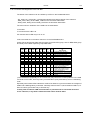
2.1.1
General
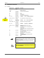
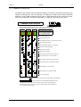
Keys in use
1-9
Y/N
b
ALT+89/
ALT+78
ALT+78
ALT+73
ALT+82
ALT+97 –
ALT+115
A+65 –
ALT+83
ALT+119 –
ALT+122
ALT+87 –
ALT+90
ALT+99 –
ALT+118
ALT+67 –
ALT+86
ALT+98
B
ALT+66
T
ALT+84
M
ALT+77
Q
ALT+81
N
I
R
A <-> S
Shift + A <-> S
Note!
Keep CapsLock
OFF when
adjusting
Alternative
keys
W <-> Z
Shift + W <-> Z
C <-> V
Shift + C <-> V
2-3
Function
Module selection
To save / cancel changes
Next
Initialisation
To restore old adjustment
1. Motor,
Left <-> Right movement
Left - Right with a long movement
2. Motor,
Up <-> Down movement
Up-Down with a long movement
3. Motor,
Forward <-> Backward
Forward - Backward with a long
movement
To read barcode in the reagent disk /
sample disk.
(In the sample disk, the segment barcode
is read.)
In the sample disk, segment and tube
barcodes are read.
Automatic BCR reading position
adjustment
To rotate mixer when adjusting mixer
cuvette positions
Quit
Note!
During adjustment program, sample / reagent covers can
be taken off. In that time the analyzer is not responding to
the opening of covers.
Attach the covers back before quitting the adjustment
program.
Note!
After each maintenance or adjustment procedure QC
run is recommended !
November 2, 2003
48953054-4081
Konelab Service Manual
2-4
Adjustments
Version I
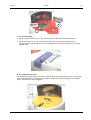
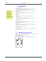
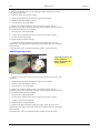
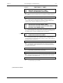
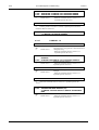
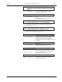
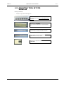
2.1.2 How to Start Adjusting ?
• Open Konelab user interface:
• Click Main -button
• Press F8 -key (More)
• Press F2 -key (Instr. Actions)
• Press F8 (More)
• Press F5 (Adjustment program)
Konelab Service Manual
48953054-4081
November 2, 2003
Version I
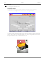
Adjustments
2-5
Recommended order to adjust
• Cuvette unit
• Incubator
• Reagent unit
• Sample unit
• Measuring unit
• ISE unit
• KUSTI unit
Good to know
• The instrument adjusts 'Syringe zero position' automatically. (refer
section 2.1.10)
• The instrument performs ‘Cuvette movement test’ automatically
• 'Fetch new cuvette to incubator position' is recommended to use
when a cuvette has to be moved to the selected incubator position. (E.g.
for adjustment of measuring positions in measuring unit (refer section
2.1.7.3))
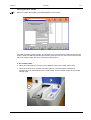
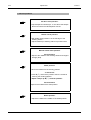
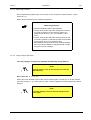
Note!
After each adjustment section program asks:
"Save adjustments (y / n) ?"
Press key Y (yes) to save adjustments automatically
to internal PC hard disk.
Dispenser needles / Mixer paddle
• Before the adjustment of dispensers and mixer, the arms of them have to
be adjusted mechanically so that needles go to their checking points.
Refer to checking points below.
Needle / Paddle checking points are the following:
Reagent Dispenser
Sample Dispenser
ISE dispenser
KUSTI dispenser
Mixers
November 2, 2003
The hole in the reagent dispensing
station
The hole in the sample dispensing
station
The left edge of the washing station
The right edge of the washing
station
The right edge of the dispensing
hole in the reagent / sample
dispensing station
48953054-4081
Konelab Service Manual
2-6
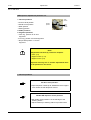
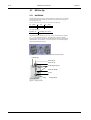
2.1.3
Adjustments
Version I
Cuvette Unit
Adjustment tools needed:
• a feeler gauge (886650)
Note!
Pusher is moving cuvettes from the revolver to the
cuvette feeder.
Mover is moving cuvettes from the feeder to the
incubator.
Cuvette unit adjustments are:
1. Revolver
2. Latch
3. Pusher
4. Mover
Note!
• Remove all cuvettes from feeder.
• Keep the menu order when adjusting, especially if
the instrument is new or adjustments are in
disorder.
Konelab Service Manual
48953054-4081
November 2, 2003
Version I
Adjustments
2-7
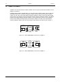
1. Revolver
Note!
Make sure that the pusher is not blocking the
revolver movement.
Revolver 1 position:
• Adjust revolver slot 1straight against cuvette feeder.
Revolver positions 2-6 are adjusted in a similar way.
Revolver free position:
• Pusher must move freely to open position.
Save adjustments y/n?
November 2, 2003
48953054-4081
Konelab Service Manual
2-8
Adjustments
Version I
2. Latch
Note!
Make sure that the pusher is not blocking the
revolver movement.
Latch open position:
• When the latch is open make sure that it is below the
cuvette feeder base. Cuvettes must move over the
latch without touching it.
Latch closed position:
• The revolver must rotate freely without hitting the latch
motor axle.
Revolver part
Latch motor axle
Save adjustments y/n?
Konelab Service Manual
48953054-4081
November 2, 2003
Version I
Adjustments
2-9
3. Pusher
Note!
Make sure that the feeder is empty and revolver can
rotate freely.
Pusher open position:
• The pusher will automatically find out the location of the
opto.
• Adjust 1- 2 mm clearance between the pusher and
revolver.
Pusher position for cuvette fetch:
• Insert one cuvette into the loader when command is
seen on the screen.
First the program will automatically adjust the distance to cuvette sensing opto.
For example:
-
On the screen is seen text : "Adjusting pusher position for cuvette fetch, opto detected at 74063".
-
Compare opto value to adjustment value.
-
Adjust 4-6 steps more from detection point. Adjustment absolute value must be bigger.
Note!
Each time when Pusher position for cuvette fetch is
adjusted, Incubator (2.1.4) Cuvette loader position
must be checked /adjusted.
Save adjustments y/n?
November 2, 2003
48953054-4081
Konelab Service Manual
2-10
Adjustments
Version I
4. Mover
Note!
• Take incubator covers off.
• Turn an empty incubator position against cuvette
feeder.
Mover position in incubator:
• Mover will push one cuvette to the incubator.
• Adjust the mover that there is 0.1 mm distance between
cuvette rear end and incubator wall. Use a feeler gauge
(886650).
Save adjustments y/n?
Konelab Service Manual
48953054-4081
November 2, 2003
Version I
2.1.4
Adjustments
2-11
Incubator
Adjustment tools needed:
• Take incubator metal cover off.
• A cuvette in incubator position 1.
Incubator position1 is next to
mounting cross headed screw
and opposite side is a hole for
heating wires going under
incubator block.
Note!
All cuvette arms are powerless. Check manually
cuvette movement from incubator to stations during
adjustments.
Incubator adjustment positions are:
•
•
•
•
•
Reagent channel
Sample channel
Measuring channel
Cuvette loader
Manual cuvette exit
All positions are adjusted according the Incubator position 1. Other position (2-20) are
calculated by the software.
Reagent channel:
• Fetch cuvette manually with cuvette arm.
• Move cuvette into the channel and check that cuvette is
not touching to guiding bearings.
• Adjust incubator if needed.
November 2, 2003
48953054-4081
Konelab Service Manual
2-12
Adjustments
Version I
Sample / Measuring channel is adjusted in a similar
way.
Cuvette loader:
• Move cuvette from loader to incubator by rotating the
Mover belt wheel manually and check that the cuvette
moves straight to incubator position 1.
• Adjust incubator if needed.
Manual cuvette exit:
• In the right side of incubator vessel assembly is a
exiting hole.
• Exit cuvette manually.
• Adjust incubator if needed.
After adjustment, the program asks if wanted to check all incubator positions:
Check adjustments y/n?
If answered y (yes), all incubator positions can be checked in reagent, sample
and measurement station position.
Check all positions (1-20) with a cuvette, because incubator motor steps are
not equal. Adjust the position 1 again if necessary. The final adjustment should
be the best possible choice for all incubator positions (1-20).
Save adjustments y/n?
Konelab Service Manual
48953054-4081
November 2, 2003
Version I
2.1.5
Adjustments
2-13
Reagent Unit
2.1.5.1 Cuvette Arm
Adjustment tools needed:
• A cuvette in incubator position 1.
• feeler gauge (886650)
Cuvette arm adjustment position is:
• Incubator position
Incubator position:
• The adjustment is valid when you can hardly lift the
feeler gauge (0.1 mm) from the space between the
cuvette rear end and the incubator wall .
Save adjustments y/n?
November 2, 2003
48953054-4081
Konelab Service Manual
2-14
2.1.5.2
Adjustments
Version I
Reagent Disk
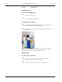
Adjustment tools needed:
• Empty bar-coded 20 ml reagent bottle
Reagent disk adjustment positions are:
• Vial inserting position
• Barcode reader position
Vial inserting position:
• Open vial/inserting cover and insert a reagent bottle to
disk.
• Adjust reagent disk if needed.
Barcode reader position:
• Press b to read the reagent bottle barcode.
• If reading is OK, no beep is heard. By adjusting the
disk, find the both ends of the reading area until beep
sound is heard.
• Count the steps from side to side and set the
adjustment to the middle.
Save adjustments y/n?
Konelab Service Manual
48953054-4081
November 2, 2003
Version I
Adjustments
2-15
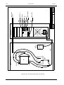
2.1.5.3 Reagent Dispenser
Reagent dispenser adjustment positions are:
•
•
•
•
Dividing partition
1. General positions
2. Cuvette positions
3. Reagent positions
8. Test wash
Wash position
Resting position
Extra wash
position
1. General positions
•
•
•
•
•
•
Phi drive level position
Needle check position
Manual needle wash position
Wash position
Extra wash position
Resting position
Phi drive level:
• Adjust needle tip 3 - 4 mm above the reagent disk
where the reagent dispenser moves.
Needle check position:
• The needle check position is a hole in the reagent
dispensing station.
• Adjust the needle tip close to the dispensing station's
top surface level.
Manual needle wash position:
• Adjust the needle to the middle of the washing station
and reagent dispensing unit. ( = 15 long steps from
edge of the washing station)
November 2, 2003
48953054-4081
Konelab Service Manual
2-16
Adjustments
Version I
Wash position:
• Move the needle over the dividing partition.
Y-movement:
• Press Z ( ß ) and find the position when the needle is
touching the dividing partition.
• Adjust 3 steps up W ( Ý ) from the partition
Phi-movement:
• Adjust back to the middle of the wash position.
Extra wash position:
Phi movement:
• Adjust to the middle of the extra wash position.
• Wash position Y-movement adj. value is used in Extra
wash position.
Resting position:
• Dispenser arm is adjusted 1 mm above the stick.
• Adjust the Phi-movement to the middle of the resting
position.
Save adjustments y/n?
Konelab Service Manual
48953054-4081
November 2, 2003
Version I
Adjustments
2-17
2. Cuvette positions
• Cuvette cell 1 upper position
• Cuvette cell 1 position
• Cuvette cell 12 position
Note!
Cuvette arm is adjusted cell 1 upper / cell 1
positions.
• Insert a cuvette into the reagent arm if there is not already.
Cuvette cell 1 upper position:
Phi-movement:
• Adjust dispenser needle to the middle of the cuvette cell
Cuvette arm:
• Adjust arm that needle is in the middle of the cuvette
cell 1.
Y-movement:
• Adjust the needle tip 1 mm under the cuvette top
surface.
Cuvette cell 1 position:
Phi-movement:
• Adjust dispenser needle to the middle of the cuvette cell
1.
Cuvette arm:
• Adjust arm that needle is in the middle of the cuvette
cell 1.
Y-movement:
• Press Z ( ß ) and find the position when the needle is
touching the bottom of the cuvette.
• Adjust 3 steps up W ( Ý ) from the bottom.
November 2, 2003
48953054-4081
Konelab Service Manual
2-18
Adjustments
Version I
Cuvette cell 12 position:
Phi-movement:
• Adjust dispenser needle to the middle of the cuvette cell
12.
Y-movement:
• Press Z (ß ) and find the position when the needle is
touching the bottom of the cuvette.
• Adjust 3 steps up W ( Ý ) from the bottom.
Save adjustments y/n?
Konelab Service Manual
48953054-4081
November 2, 2003
Version I
Adjustments
2-19
3. Reagent position:
• Cuvette cell 1 upper position
• Cuvette cell 1 position
• Cuvette cell 12 position
Note!
• Take reagent cover off.
• Insert 20 ml reagent bottle into the reagent disk
positions 1, 12, 23 and 35.
• Each reagent bottle position have an own bottom
adjustment value.
Reagent disk position cups:
Phi-movement:
• Adjust dispenser needle to middle of the bottle neck.
Reagent disk:
• Adjust disk that the needle is in middle of the bottle
neck.
Y-movement:
• Press Z ( ß ) and find the position when the needle is
touching the bottom of the bottle.
• Adjust 4 steps up W ( Ý ) from the bottom.
Positions 12, 23 and 33:
• Check Y-movement 4 steps up from the bottom.
Save adjustments ?
November 2, 2003
48953054-4081
Konelab Service Manual
2-20
Adjustments
Version I
2.1.5.4 Reagent Mixer
Reagent mixer adjustment positions are:
• 1. General positions
• 2. Cuvette positions
• 9. Test mixing in cuvette
Wash position
1. General positions
• Phi drive level position
• Paddle check position
• Manual needle wash position
• Wash position
• Resting position
Phi drive level:
• Adjust mixer paddle tip 4-5 mm above the reagent
dispensing station.
Paddle check position:
• Adjust the mixer paddle tip to the right edge of the
dispensing hole in the reagent dispensing station.
• Adjust the paddle tip close to the dispensing station's
upper surface level.
Manual needle wash position:
Phi-movement:
• Adjust mixer paddle to the middle of the dispensing
reagent unit. ( = 120 long steps from the wash position)
Y-movement:
• Adjust mixer paddle tip 20 long steps up from the
surface of the washing station.
Konelab Service Manual
48953054-4081
November 2, 2003
Version I
Adjustments
2-21
Wash position:
Phi-movement:
• Adjust mixer paddle to the middle of the washing
position.
Y-movement:
• Straight part of the paddle is above the washing station
as shown in figure under.
Resting position:
Phi-movement:
• Adjust paddle to the middle of the wash position.
Y-movement:
• Adjust the mixer arm 1 mm above the rubber.
Save adjustments y/n ?
November 2, 2003
48953054-4081
Konelab Service Manual
2-22
Adjustments
Version I
2. Cuvette positions
• Insert a cuvette into the reagent arm if there is not already.
Cuvette cell 1position:
Phi-movement:
• Adjust the mixer paddle to the middle of the cuvette cell.
Y-movement:
• Press Z ( ß ) and find the position when the paddle is
touching the bottom of the cuvette.
• Adjust 3 steps up W ( Ý ) from the bottom.
• Press key m to check that the mixer can rotate
freely.
Cuvette cell 12 position:
Phi-movement:
• Adjust the mixer paddle to the middle of the cuvette cell.
Y-movement:
• Press Z ( ß ) and find the position when the paddle is
touching the bottom of the cuvette.
• Adjust 3 steps up W ( Ý ) from the bottom.
• Press key m to check that the mixer can rotate
freely.
Save adjustments y/n?
9. Test mixing in cuvette:
• Mixing is tested in all 12 positions in cuvette.
• If mixing is noisy, readjust cuvette cell 1 and 12 positions.
Konelab Service Manual
48953054-4081
November 2, 2003
Version I
2.1.6
Adjustments
2-23
Sample Unit
2.1.6.1 Cuvette Arm
Adjustment tools needed:
• A cuvette in incubator position 1.
• feeler gauge (886650)
Cuvette arm adjustment is:
Incubator position:
• The adjustment is valid when you can hardly lift the
feeler gauge (0.1 mm) from the space between the
cuvette rear end and the incubator wall.
Save adjustments y/n ?
November 2, 2003
48953054-4081
Konelab Service Manual
2-24
Adjustments
Version I
2.1.6.2 Sample Disk
Sample disk adjustments are:
• Segment / vial inserting position, segments 1-6
• Barcode reader position, segments 1-6
• STAT sample inserting, positions 1-6
• Barcode reader position, STAT samples 1-6
• Segment loader positions
Note!
• Segment loader is powerless during adjustment.
• It can be moved manually. Be sure that loader is not
blocking sample disk movement when entering
next position.
• Take sample cover off.
Segment / vial inserting position segment position 1:
• Move the segment loader to down position
• Adjust the disk that segment is in correct position when
loader lifts it out.
• Check movement manually that segment loader´s 2
pins goes straight through segment´s bottom plate
holes.
Note!
Good quality barcode
stickers are needed.
Konelab Service Manual
48953054-4081
November 2, 2003
Version I
Adjustments
2-25
Barcode reader position segment position 1:
• Insert a segment with barcoded sample tubes into the
sample disk position 1.
• Press b to read the segment barcode. If reading is
OK, no beep is heard. By adjusting the disk, find the
both ends of the reading area until beep sound is
heard.
• Count the steps from side to side and set the
adjustment to the middle.
Automatic BCR adjustment:
• After the segment barcode reading position is adjusted,
the analyser will adjust the barcode reading positions
automatically for all sample tubes. Press T to start
adjustment.
• When the automatic adjustment has been made, new
and old values are seen on the screen and asked:
Save new values y/n?
• You can check the segment and tube barcode readings.
Press B (Shift + b).
• When the first segment has been adjusted the program
asks if the user wants that all other 5 segment positions
are calculated:
Calculate other segment positions before adjusting
them? y/n Choose Yes.
Note! All other positions (2-6) are adjusted in a
similar way.
• Save adjustments y/n?
STAT sample inserting position:
• With cover on, insert a sample tube into the STAT
sample position 1.
• Adjust disk if needed.
November 2, 2003
48953054-4081
Konelab Service Manual
2-26
Adjustments
Version I
Barcode reader position:
• Insert barcoded sample tube into the STAT sample
position 1.
• Press b to read the sample tube barcode. If reading
is OK, no beep is heard. By adjusting the disk, find the
both ends of the reading area until beep sound is
heard.
• Count the steps from side to side and set the
adjustment to the middle.
• When the STAT sample position 1 has been adjusted,
the program asks if the user wants that all other 5
STAT sample positions are calculated:
Calculate other STAT positions before adjusting them?
y/n. Choose Yes.
STAT sample inserting / barcode positions 2-6 are
adjusted in a similar way.
• Save adjustments y/n?
Segment loader positions:
Segment loader up position:
• Segment must rest over the sample unit, not over the
segment loader. Adjust about 1 mm space between
the segment bottom and loader.
1 mm space between segment and loader
Important!
Sample disk position 1 must be empty. Close the
segment loader cover before next (n) position.
Konelab Service Manual
48953054-4081
November 2, 2003
Version I
Adjustments
2-27
Segment loader positions
Segment loader down position:
• Adjust the loader that the sample disk can rotate freely
without touching the segment loader pins.
• Distance between sample disk bottom and loader pins
is 2-3 mm. DO NOT adjust it lower because the loaders
mechanical movement area ends.
• Save adjustments y/n?
November 2, 2003
48953054-4081
Konelab Service Manual
2-28
2.1.6.3
Adjustments
Version I
Sample Dispenser
Dispenser adjustment positions are:
1. General positions
Dividing partition
• Phi drive level position
• Needle check position
• Manual needle wash position
• Wash position
• Extra wash position
• Resting position
Wash position
Resting position
Extra wash
position
2. Cuvette positions
4. STAT positions, all 6
5. Standard / Control positions, all 40
6. Segment positions
• Outer ring, position 10 for all 6 segments
• Inner ring, position 3 for all 6 segments
• Sample tube in position 11 for the segment position 1
7. KUSTI segment positions
8. Test wash
1. General positions
Phi drive level position:
• Adjust dispenser needle 3 - 4 mm above the sample
disk where the sample dispenser moves.
Needle check position:
• The needle check position is a hole in the sample
dispensing station. Adjust the needle tip to the
dispensing station's top surface level.
Manual needle wash position:
• Adjust dispenser needle 20 long steps outside from
edge of the sample disk.
Konelab Service Manual
48953054-4081
November 2, 2003
Version I
Adjustments
2-29
Wash position:
• Move the needle over the dividing partition.
Y-movement:
• Press Z ( ß ) and find the position when the needle is
touching the dividing partition.
• Adjust 3 steps up W ( Ý ) from the partition.
Phi movement:
• Adjust to the middle of the wash position.
Extra wash position:
Phi movement:
• Adjust to the middle of the extra wash position. Wash
position Y-movement adj. value is used in Extra wash
position.
Resting position:
• Dispenser arm is adjusted about 1 mm above the stick.
• Adjust the Phi-movement to the middle of the resting
position.
Save adjustments y/n?
November 2, 2003
48953054-4081
Konelab Service Manual
2-30
Adjustments
Version I
2. Cuvette positions
• Cuvette cell 1 upper position
• Cuvette cell 1 position
• Cuvette cell 12 position
Insert a cuvette into the sample
arm if there is not already. (refer
section 2.1.6.1)
Note!
Incubator is adjusted cell 1 upper / cell 1 positions.
Cuvette cell 1 upper position:
Phi-movement:
• Adjust dispenser needle to the middle of the cuvette cell
1.
Cuvette arm:
• Adjust arm that needle is in the middle of the cuvette
cell 1.
Y-movement:
• adjust the needle tip 1 mm under the cuvette top
surface.
Cuvette cell 1 position
Phi-movement:
• Adjust dispenser needle to the middle of the cuvette cell
1.
Cuvette arm:
• Adjust arm that needle is in the middle of the cuvette
cell 1.
Y-movement:
• Press Z ( ß ) and find the position when the needle is
touching the bottom of the cuvette.
• Adjust 3 steps up W ( Ý ) from the bottom.
Konelab Service Manual
48953054-4081
November 2, 2003
Version I
Adjustments
2-31
Cuvette cell 12 position
Phi-movement:
• Adjust dispenser needle to the middle of the cuvette cell
12.
Y-movement:
• Press Z ( ß ) and find the position when the needle is
touching the bottom of the cuvette.
• Adjust 3 steps up W ( Ý ) from the bottom.
Save adjustments y/n?
Note!
Sample disk has four (4) circles for samples:
• STAT (1-6)
• Std/Ctrl (40)
• Segment outer (8-14)
• Segment inner (1-7)
• (KUSTI segment rings 1 to 5)
Dispenser has only one Y- and Phi- adjustment value
for all positions in one circle.
November 2, 2003
48953054-4081
Konelab Service Manual
2-32
Adjustments
Version I
4. STAT positions
Note!
Take sample cover off and insert 0.5 ml cups into the
STAT positions.
Phi-movement:
• Adjust dispenser needle into the middle of sample cup.
Sample disk:
• Adjust disk that the needle is in the middle of the
sample cup.
Y-movement:
• Press Z ( ß ) and find the position when the needle is
touching the sample cup bottom.
• Adjust 2 steps up W ( Ý ) from the bottom.
When the first STAT position has been adjusted the program asks if the user
wants that all other 5 STAT positions are calculated:
Calculate other STAT positions before adjusting them? y/n
Choose Yes.
Check all STAT positions one by one that the needle goes to the middle of
the cup without touching the cup bottom.
Save adjustments y/n?
Konelab Service Manual
48953054-4081
November 2, 2003
Version I
Adjustments
2-33
5. Standard / Control positions
Note!
Insert 0.5 ml cups into the ISE PRIME, C10, S0 and
S10 positions and place the sample disk cover and
STD/CTRL plastic cover on.
Phi-movement:
• Adjust the dispenser needle into the middle of sample
cup.
Sample disk:
• Adjust disk that the needle is in the middle of the
sample cup.
Y-movement:
• Press Z ( ß ) and find the position when the needle is
touching the sample cup bottom.
• Adjust 2 steps up W ( Ý ) from the bottom.
When the ISE wash/prime position has been adjusted the program asks if the
user wants that all other Std / Ctrl positions are calculated:
Calculate other Std / Ctrl positions before adjusting them? y/n
Choose Yes.
Check Std /Ctrl sample positions C10, S0 and S10 that the needle goes to
the middle of the cup without touching the cup bottom.
Save adjustments y/n?
November 2, 2003
48953054-4081
Konelab Service Manual
2-34
Adjustments
Version I
6. Segment positions
Note!
• Take sample cover off.
• Insert 0.5 ml cups into the segment positions 3 and
10 and a sample tube into the position 11.
• Insert segment to the sample disk position 1.
• Insert second segment with cups in positions 3 and
10 to sample disk position 2.
Cup position 10 adjustment:
Phi-movement:
• Adjust the dispenser needle into the middle of sample
cup.
Sample disk:
• Adjust disk that the needle is in the middle of the
sample cup.
Y-movement:
• Press Z ( ß ) and find the position when the needle is
touching the sample cup bottom.
• Adjust 3 steps up W ( Ý ) from the bottom.
Cup position 3 is adjusted in a similar way.
Tube bottom level in the position 11:
• Press Z ( ß ) and find the position when the needle is
touching the tube bottom.
• Adjust as many steps up W ( Ý ) from the bottom as
is reasonable.
When the first segment has been adjusted the program asks if the user wants
that all other 5 segment positions are calculated:
Calculate other segment positions before adjusting them? y/n
Choose Yes.
Check all segments positions 3 and 10 one by one that the needle goes into
the middle of the cup without touching the cup bottom. Tube bottom level is
adjusted only once in disk position 1.
Save adjustments y/n?
Konelab Service Manual
48953054-4081
November 2, 2003
Version I
Adjustments
2-35
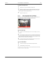
7. KUSTI segment positions
Note!
• Take sample cover off and insert KUSTI segments
into the sample disk position 1 and 2
Ring5
Cup 1
Ring4
Cup 17
Ring3
Cup 35 Ring2
Cup 53 Ring1
Cup 73
Phi-movement:
• Adjust the dispenser needle into the middle of the ring 1
cup position 73.
Sample disk:
• Adjust disk that the dispenser needle is in the middle of
the ring 1 cup position 73.
Y-movement:
• Press Z ( ß ) and find the position when the needle is
touching the bottom.
• Adjust 3 steps up W ( Ý ) from the bottom.
Ring2 /cup 53 , ring3 / cup35 , ring4 / cup17 and ring5 / cup1 are adjusted in
a similar way.
When all positions in the first segment has been adjusted the program asks if the
user wants that all other segment positions are calculated:
Calculate other segment positions before adjusting them y/n?
Choose Yes.
All other segment positions 2 - 6 are adjusted in a similar way.
Save adjustments y/n ?
November 2, 2003
48953054-4081
Konelab Service Manual
2-36
Adjustments
Version I
2.1.6.4 Sample Mixer
Sample mixer adjustment positions are:
• General positions
• Cuvette positions
• Test mixing in cuvette
Wash position
1. General positions
• Phi drive level position
• Paddle check position
• Manual needle wash position
• Wash position
• Resting position
Phi drive level:
• Adjust mixer paddle tip 4 - 5 mm above the sample
dispensing channel where the mixer moves. (Note that
mixer does not touch the wires on dispensing channel.)
Check position:
• Adjust the mixer paddle tip in the left edge of the
washing station and to the top surface level of the
washing station.
Manual needle wash position
Phi-movement:
• Adjust mixer paddle to the middle of the sample
dispensing unit.( = 227 long steps from wash position)
Y-movement:
• Adjust mixer paddle tip 20 long steps up from surface of
the washing station.
Konelab Service Manual
48953054-4081
November 2, 2003
Version I
Adjustments
2-37
Wash position
Phi-movement:
• Adjust mixer paddle to the middle of the washing
position.
Y-movement:
• Straight part of the paddle is above the washing station
as shown in figure under.
Resting position:
Phi-movement:
• Adjust paddle to the middle of the wash position.
Y-movement:
• Adjust the mixer arm 1 mm above the rubber.
Save adjustments y/n?
November 2, 2003
48953054-4081
Konelab Service Manual
2-38
Adjustments
Version I
2. Cuvette positions
• Insert a cuvette into the reagent arm if there is not already.
Cuvette cell 1 position:
Phi-movement:
• Adjust the mixer paddle into the middle of the cuvette
cell.
Y-movement:
• Press Z ( ß ) and find the position when the paddle is
touching the bottom of the cuvette.
• Adjust 3 steps up W ( Ý ) from the bottom.
• Press key m to check that the mixer can rotate
freely.
Cuvette cell 12 position:
Phi-movement:
• adjust the mixer paddle to the middle of the cuvette cell.
Y-movement:
• Press Z ( ß ) and find the position when the paddle is
touching the bottom of the cuvette.
• Adjust 3 steps up W ( Ý ) from the bottom.
• Press key m to check that the mixer can rotate
freely.
Save adjustments y/n?
3. Test mixing in cuvette:
• Mixing is tested in all 12 positions in cuvette.
• If mixing is noisy, readjust cuvette cell 1 and 12 positions.
Konelab Service Manual
48953054-4081
November 2, 2003
Version I
2.1.7
Adjustments
2-39
Measuring Unit
Measuring unit adjustment positions are:
• Cuvette arm
• Filter disk/ beam alignment
• Measuring positions
• Lamp voltages and gains
2.1.7.1 Cuvette Arm
Adjustment tools needed:
• A cuvette in incubator position 1
• A feeler gauge (886650)
1. Cuvette arm adjustment positions:
• Incubator positions 1, 6, 11 and 16
• Cuvette exit position
Note!
• Cuvette arm is adjusted with incubators 4 side
because it is always slightly uneven and all
positions are not exactly equal from the cuvette
arms point of view.
• Program calculates the difference between pos. 1 16 and uses it also with reagent and sample
cuvette arms.
Incubator position:
• Rotate incubator position 1 against cuvette arm. The
adjustment is valid when you can hardly lift the feeler
gauge (0.1 mm) from the space between the cuvette
rear end and the incubator wall .
• Adjust the positions 1, 6, 11 and 16. Each position has
an own adjustment value.
November 2, 2003
48953054-4081
Konelab Service Manual
2-40
Adjustments
Version I
Cuvette exit position:
• Adjust position 4 long steps ( Ý+S ) toward incubator
and save adjustments.
• Insert a cuvette to incubator position 1 and enter
the Cuvette arm menu again.
• In exit position, press the adjustment key ( A ) until
you find the position where the cuvette will drop to the
waste compartment.
• Adjust 20 steps more ( key A ) from the dropping
point.
• Save adjustments y/n?
Konelab Service Manual
48953054-4081
November 2, 2003
Version I
Adjustments
2-41
2.1.7.2 Filter Disk / Beam Alignment
• When filter disk / beam alignment is selected, the
instrument first drives the filter wheel into its empty
position (15).
• Adjust the light spot over the fiber bundle. (refer to
figure below). Adjustment is done by the adjustment
screws in the lamp assembly.
Light spot
Fiber bundle
Filter wheel filter position 1
• Adjust filter wheel that the lamp beam is in the middle of
the 1 filter cover.
Save adjustments y/n ?
Note!
After filter wheel adjustment procedure QC run is
recommended !
November 2, 2003
48953054-4081
Konelab Service Manual
2-42
Adjustments
Version I
2.1.7.3 Measuring Positions
Quit to adjustment program main menu to fetch a new cuvette to incubator position 1 (refer
section 2.1.2 )
Return back to Measuring unit / Measuring positions.
Measuring positions:
• Instrument adjusts positions automatically.
• Program finds cuvette cell walls starting from rear end
of cuvette (=position 12) and sets the value to the
middle of the cell one by one. (In software 5.0.X or
lower).
• Program finds cuvette cell walls starting from front end
of cuvette (=position 1) and sets the value to the middle
of the cell one by one. (In software 6.0.X).
• After adjustment is seen old and new values and asked:
Save new values YES/NO.
If adjustment fails, it stops and gives an error message.
2.1.7.4 Lamp Voltages and Gains
The lamp voltages and gains are adjusted automatically during Start up.
Note!
Results what are seen in this function are from the
latest Start up.
Gain values are: 0, 1, 2, 3, 4, 5.
When gain is low the filter is good. With 340 and 380 the gain is usually 2 or 3. All the rest filter
gains are usually 0, 1 or 2. If the gain is 5, filter or lamp is getting old or beam alignment is bad or
blocked.
Note!
The lamp voltage is 0 when the filter position has a
cover plate.
Konelab Service Manual
48953054-4081
November 2, 2003
Version I
2.1.8
Adjustments
2-43
ISE Unit
ISE dispenser adjustment positions are:
1.General positions
• Phi drive level position
• Needle check position
• Manual needle wash position
• Wash position
• Resting position
4.STAT positions, all 6
Wash position
Dividing partition
Waste/ resting
position
5.Standard / Control positions, all
40
6.Segment positions,
• outer ring, position 10 for all 6
segments
• inner ring, position 3 for all 6
segments
• sample tube position 11 for the
segment 1
7. KUSTI segment positions
8. Test wash
Note!
Sample disk has four (4) circles for samples:
• STAT (1-6)
• Std /Ctrl (40)
• Segment outer (8-14)
• Segment inner (1-7)
• (KUSTI segment rings 1 to 5)
ISE dispenser has only one Y- and Phi- adjustment
value for all positions in one circle.
November 2, 2003
48953054-4081
Konelab Service Manual
2-44
Adjustments
Version I
1. General positions
Phi drive level position:
• Adjust dispenser needle tip 3 - 4 mm above the sample
disk cover where the ISE dispenser moves.
Needle check position:
• ISE needle check position is in the left edge of the
washing station.
• Adjust needle tip to washing station top surface level.
Manual needle wash position:
Phi-movement:
• Adjust to the middle of the washing station and reagent
storage (disk).
Wash position:
• Move the needle over the dividing partition.
Y-movement:
• Press Z ( ß ) and find the position when the needle is
touching the dividing partition.
• Adjust 3 steps up W ( Ý ) from the partition.
Phi-movement:
Adjust to the middle of the wash position.
Waste position:
• Adjust the needle to the middle of the waste position.
Konelab Service Manual
48953054-4081
November 2, 2003
Version I
Adjustments
2-45
Resting position:
• Adjust dispenser arm about 1 mm above the stick.
• Adjust the dispenser needle to the middle of the resting
position.
Save adjustments y/n?
2. STAT positions
Note!
Take sample cover off and insert 0.5 ml cups into the
STAT positions.
Phi-movement:
• Adjust dispenser needle into the middle of sample cup.
Sample disk:
• Adjust disk that the needle is in the middle of the
sample cup.
Y-movement:
• Press Z ( ß ) and find the position when the needle is
touching the sample cup bottom.
• Adjust 2 steps up W ( Ý ) from the bottom.
When the STAT position 1 has been adjusted the program asks if the user wants all other 5 STAT
positions to be calculated:
Calculate all STAT positions before adjusting them? y/n
Choose Yes.
Check all STAT sample positions one by one that the needle goes to the middle of the cup
without touching the cup bottom.
Save adjustments y/n?
November 2, 2003
48953054-4081
Konelab Service Manual
2-46
Adjustments
Version I
3. Standard / Control positions
Note!
Insert 0.5 ml cups into the ISE PRIME, C10, S0 and
S10 positions and place the sample disk cover and
STD/CTRL plastic cover on.
Phi-movement:
• Adjust dispenser needle into the middle of sample cup.
Sample disk:
• Adjust disk that the needle is in the middle of the
sample cup.
-Y-movement:
• Press Z ( ß ) and find the position when the needle is
touching the sample cup bottom.
• Adjust 2 steps up W ( Ý ) from the bottom.
When the ISE PRIME position has been adjusted the program asks if the user wants that all other
positions are calculated:
Calculate all other positions before adjusting them? y/n
Choose Yes.
Check STD/CTRL sample positions C10, S0 and S10 that the needle goes to the middle of the
cup without touching the cup bottom.
Save adjustments y/n?
Konelab Service Manual
48953054-4081
November 2, 2003
Version I
Adjustments
2-47
4. Segment positions
Note!
• Take sample cover off.
• Insert 0.5 ml cups into the segment positions 3 and
10 and a sample tube into the position 11.
• Insert segment to the sample disk position 1.
• Insert second segment with cups in positions 3 and
10 to sample disk position 2.
Cup position 10 adjustment:
Phi-movement:
• Adjust the dispenser needle into the middle of sample
cup.
Sample disk:
• Adjust disk that the needle is in the middle of the
sample cup.
Y-movement:
• Press Z (ß) and find the position when the needle is
touching the sample cup bottom.
• Adjust 2 steps up W ( Ý ) from the bottom.
Cup position 3 is adjusted in a similar way.
Tube bottom level in the position 11:
• Press Z ( ß ) and find the position when the needle is
touching the tube bottom.
• Adjust as many steps up W ( Ý ) from the bottom as
is reasonable.
When positions in the first segment has been adjusted, the program asks if the user wants that all
other positions are calculated:
Calculate all other positions before adjusting them? y/n
Choose Yes.
Check all segments positions 3 and 10 one by one that the needle goes into the middle of the cup
without touching the cup bottom. Tube bottom level is adjusted only once in segment 1.
Save adjustments y/n?
November 2, 2003
48953054-4081
Konelab Service Manual
2-48
Adjustments
Version I
7. KUSTI segment positions
Note!
Take sample cover off and insert KUSTI segments
into the sample disk positions 1 and 2.
Ring5
Cup 1
Ring4
Cup 17
Ring3
Cup 35 Ring2
Cup 53 Ring1
Cup 73
Phi-movement:
• Adjust the ISE dispenser needle into the middle of the
ring 1 cup position 73.
Sample disk:
• Adjust disk that the ISE dispenser needle is in the
middle of the ring 1 cup position 73.
Y-movement:
• Press Z ( ß ) and find the position when the needle is
touching the bottom.
• Adjust 3 steps up W( Ý ) from the bottom.
Ring2 /cup 53 , ring3 / cup35 , ring4 / cup17 and ring5 / cup1 are adjusted in a similar way.
When all positions in the first segment has been adjusted the program asks if the user wants that
all other segment positions are calculated:
Calculate other segment positions before adjusting them y/n?
Choose Yes.
All other segment positions 2 - 6 are adjusted in a similar way.
Save adjustments y/n?
Konelab Service Manual
48953054-4081
November 2, 2003
Version I
2.1.9
Adjustments
2-49
KUSTI Unit
KUSTI dispenser adjustment positions are:
Dividing partition
1. General positions
•
•
•
•
•
•
Phi drive level position
Needle check position
Manual needle wash position
Wash position
Extra wash position
Resting position
Wash
position
Resting
position
Extra wash
position
2. Sample transfer line position
7. KUSTI segment positions
8. Test wash
1. General positions
Phi drive level:
• Adjust dispenser needle tip 2 - 3 mm above the sample
disk cover where the KUSTI dispenser moves.
Needle check position:
• The needle check position is in the right edge of the
washing station.
• Adjust the needle tip to the washing station top surface
level.
Manual needle wash position:
Phi-movement:
• Adjust the needle over the bottle of washing solution
November 2, 2003
48953054-4081
Konelab Service Manual
2-50
Adjustments
Version I
F Wash position:
• Move the needle over the dividing partition.
Y-movement:
• Press Z ( ß ) and find the position when the needle is
touching the dividing partition.
• Adjust 3 steps up W ( Ý ) from the partition
Phi-movement:
• Adjust to the middle of the wash position.
Extra wash position:
Phi movement:
• Adjust to the middle of the extra wash position. Wash
position Y-movement adj. value is used in Extra wash
position.
Resting position:
• Dispenser arm is adjusted 1mm above the rubber .
• Adjust the Phi-movement to the left side of washing
station.
Save adjustments y/n?
Konelab Service Manual
48953054-4081
November 2, 2003
Version I
Adjustments
2-51
2. Sample transfer line position:
Note!
This adjustment is done after connecting Konelab to
Sample transfer line. Factory adjustment is over the
left end cover.
KUSTI dispenser sample transfer line position:
Phi-movement:
• Adjust KUSTI dispenser needle into the middle of the
sample tube in the sample transfer line. Y-movement is
not saved.
This adjustment is made first to move dispenser over
the sample transfer line without any danger of
breaking the needle.
KUSTI dispenser sample transfer line position:
Phi-movement:
• Adjust KUSTI dispenser needle into the middle of the
sample tube in the sample transfer line.
Y-movement:
• Press Z ( ß ) and find the position when the needle is
touching the tube bottom.
• Adjust as many steps up W ( Ý ) from the bottom as
is reasonable.
November 2, 2003
48953054-4081
Konelab Service Manual
2-52
Adjustments
Version I
3. KUSTI segment positions:
Note!
Take sample cover off and insert KUSTI segments
into the sample disk positions 1 and 2.
Ring5
Cup 1
Ring4
Cup 17
Ring3
Cup 35 Ring2
Cup 53 Ring1
Cup 73
Phi-movement:
• Adjust the KUSTI dispenser needle into the middle of
the ring 1 cup position 73.
Sample disk:
• Adjust disk that the KUSTI dispenser needle is in the
middle of the ring 1 cup position 73.
Y-movement:
• Adjust dispenser needle halfway to the cup.
Ring2 /cup 53 , ring3 / cup35 , ring4 / cup17 and ring5 / cup1 are adjusted in a similar way.
When all positions in the first segment has been adjusted the program asks if the user wants that
all other segment positions are calculated:
Calculate other segment positions before adjusting them y/n?
Choose Yes.
All other segments 2 - 6 are adjusted in a similar way.
Save adjustments y/n?
Konelab Service Manual
48953054-4081
November 2, 2003
Version I
Adjustments
2-53
2.1.10 Syringe Zero Position
Syringe zero position adjustment must be done when complete syringe unit, stepper motor or
opto has been changed.
The instrument adjusts the zero position automatically.
Error message 5065 "Syringes should be adjusted (adjustment program)" informs the
user when syringe zero position adjustment should be done.
2.1.11 Saving and Restoring Adjustment Values
2.1.11.1 Saving Adj. Values to Floppy Disk
1.
Connect display and keyboard to the internal PC.
2.
If instrument is on - quit Konelab software by pressing E.
- If instrument is off - boot the instrument. Select item 2. Command prompt from boot up
menu by pressing the arrow key down ( ß ) once and after that pressing enter.
3.
Insert formatted floppy disk to the floppy drive. Note! The floppy drive is upside down.
4.
When in the screen is displayed C://x60, copy adjustment files to the floppy disk with
command save_adj.
5.
Remove the floppy disk from the drive.
6.
Reboot the instrument.
2.1.11.2 Restoring Adj. Values from Floppy Disk
1.
Connect display and keyboard to the internal PC.
2.
Instrument is on - quit Konelab software by pressing E.
- Instrument is off - boot the instrument. Select item 2. Command prompt from boot up
menu by pressing the arrow key down ( ß ) once and after that pressing enter.
3.
Insert the floppy disk containing the adjustment values to the floppy drive. Note: Floppy
drive is upside down.
4.
When in the screen is displayed C://x60, load adjustment files from the floppy disk with
command load_adj
5.
Remove the floppy disk from the drive.
6.
Reboot the instrument.
November 2, 2003
48953054-4081
Konelab Service Manual
2-54
Konelab Service Manual
Adjustments
48953054-4081
Version I
November 2, 2003
Version I
Adjustments
2.2
Adjustments of Konelab 30
2.2.1
General
Keys in use
1-9
Y/N
b
ALT+89/
ALT+78
ALT+78
ALT+73
ALT+82
ALT+97 –
ALT+115
A+65 –
ALT+83
ALT+119 –
ALT+122
ALT+87 –
ALT+90
ALT+99 –
ALT+118
ALT+67 –
ALT+86
ALT+98
B
ALT+66
T
ALT+84
M
ALT+77
Q
ALT+81
N
I
R
A <-> S
Shift + A <-> S
Note!
Keep CapsLock
OFF when
adjusting
Alternative
keys
W <-> Z
Shift + W <-> Z
C <-> V
Shift + C <-> V
2-55
Function
Module selection
To save / cancel changes
Next
Initialisation
To restore old adjustment
1. Motor,
Left <-> Right movement
Left - Right with a long movement
2. Motor,
Up <-> Down movement
Up-Down with a long movement
3. Motor,
Forward <-> Backward
Forward - Backward with a long
movement
To read barcode in the reagent disk /
sample disk.
(In the sample disk, the segment barcode
is read.)
In the sample disk, segment and tube
barcodes are read.
Automatic BCR reading position
adjustment
To rotate mixer when adjusting mixer
cuvette positions
Quit
Note!
During adjustment program, sample / reagent covers can
be taken off. In that time the analyser is not responding to
the opening of covers.
Attach the covers back before quitting the adjustment
program.
Note!
After each maintenance or adjustment procedure QC
run is recommended !
November 2, 2003
48953054-4081
Konelab Service Manual
2-56
2.2.2
Adjustments
Version I
How to Start Adjusting ?
• Open Konelab user interface:
• Click Main -button
• Press F8 -key (More)
• Press F2 -key (Instr. Actions)
• Press F8 (More)
• Press F5 (Adjustment program)
Recommended order to adjust
• Incubator
• Cuvette unit
• Reagent disk
• Sample disk
• Measuring unit
• Dispensing unit
• ISE unit
• KUSTI unit
Konelab Service Manual
48953054-4081
November 2, 2003
Version I
Adjustments
2-57
Good to know
• The instrument adjusts 'Syringe zero position' automatically. (refer
section 2.2.9)
• 'Fetch new cuvette to incubator position' is recommended to use
when a cuvette has to be moved to the selected incubator position. (E.g.
for adjustment of measuring positions in measuring unit (refer section
2.2.6.3))
Note!
After each adjustment section program asks:
"Save adjustments (y/n) ?"
Press key Y (yes) to save adjustments
automatically to internal PC hard disk.
Dispenser needles / Mixer paddle
• Before the adjustment of dispensers and mixer, the arms of them have to
be adjusted mechanically so that dispenser needles go to their checking
points. Refer to checking points under.
Needle checking points are the following:
Dispenser
ISE dispenser
KUSTI dispenser
Mixer
November 2, 2003
The right edge of the sample side's
washing station.
The left edge of the washing station.
The right edge of the washing
station.
The left edge of the washing station.
48953054-4081
Konelab Service Manual
2-58
2.2.3
Adjustments
Version I
Incubator
Adjustment tools needed:
• a cuvette in every incubator position 1-6
• take plastic cover, incubator metal cover and black measuring channel
cover off.
Note!
Cuvette arm is powerless during incubator
adjustment.
It can be moved manually.
Incubator adjustment positions are:
• Cuvette arm positions
Cuvette arm position 1:
• Fetch manually cuvette with arm from incubator and
check that the cuvette is not touching guiding bearings.
• Adjust incubator if needed .
• Release cuvette back to incubator and fetch again.
Other Cuvette arm positions 2-6 are adjusted in a
similar way.
• Save adjustments y/n?
Konelab Service Manual
48953054-4081
November 2, 2003
Version I
2.2.4
Adjustments
2-59
Cuvette Unit
Cuvette unit adjustment positions are:
• Pusher open position
• Pusher position for cuvette fetch
Note!
Cuvette feeder must be empty!
Pusher open position:
• Pusher belt gear and the loader end belt gear nearly
touch each other.
• Adjust pusher if needed.
• Press pusher with fingers to see more clearly
adjustment movement.
Note!
Insert one (1) cuvette into the feeder when command
is seen on the screen.
Pusher position for cuvette fetch:
• First the program will automatically adjust the distance
to cuvette sensing opto.
• For example: On the screen is seen text: "Adjusting
pusher position for cuvette fetch, opto detected at 54947". Compare opto value to adjustment value and
adjust 4-6 steps more from detection point.
Adjustment value must be bigger.
• Fetch a cuvette manually from feeder and check
that cuvette aligns straight with cuvette arm.
Readjust pusher if needed.
• Press pusher down to see more clearly adjustment
movement.
• Save adjustments y/n?
November 2, 2003
48953054-4081
Konelab Service Manual
2-60
2.2.5
Adjustments
Version I
Reagent Disk
Adjustment tools needed:
• Empty barcoded 20 ml reagent bottle.
Reagent disk adjustment positions are:
• Vial inserting position
• Barcode reader position
Vial inserting position:
• Open vial / inserting cover and insert a reagent bottle to
disk.
• Adjust reagent disk if needed.
Barcode reader position:
• Press b to read the reagent bottle barcode.
• If reading is OK, no beep is heard. By adjusting the
disk, find the both ends of the reading area until beep
sound is heard. Count the steps from side to side and
set the adjustment to the middle.
• Save adjustments y/n?
Konelab Service Manual
48953054-4081
November 2, 2003
Version I
2.2.6
Adjustments
2-61
Sample Disk
Sample disk adjustments are:
•
•
•
•
•
Segment / vial inserting position, segments 1-6
Barcode reader position, segments 1-6
STAT sample inserting, positions 1-6
Barcode reader position, STAT samples 1-6
Segment loader positions
Note!
Segment loader is powerless during adjustment. It
can be moved manually. Be sure that loader is not
blocking sample disk movement when entering next
position.
Take sample cover off.
Segment / vial inserting position segment position 1:
• Move the segment loader to down position
• Adjust the disk that segment is in correct position when
loader lifts it out.
• Check movement manually that segment loader´s 2
pins goes straight through segment´s bottom plate
holes.
Pins
Pins
November 2, 2003
48953054-4081
Konelab Service Manual
2-62
Adjustments
Version I
Barcode reader position segment position 1:
• Insert a segment with barcoded sample tubes into the
sample disk position 1.
• Press b to read the segment barcode. If reading is
OK, no beep is heard. By adjusting the disk, find the
both ends of the reading area until beep sound is
heard. Count the steps from side to side and set the
adjustment to the middle.
Note!
Good quality barcode
stickers are needed.
Automatic BCR adjustment:
• After the segment barcode reading position is adjusted,
the analyser will adjust the barcode reading positions
automatically for all sample tubes. Press T to start
adjustment.
• When the automatic adjustment has been made, new
and old values are seen on the screen and asked:
Save new values y/n?
• You can check the segment and tube barcode readings.
Press B (Shift + b).
• When the first segment has been adjusted the program
asks if the user wants that all other 5 segment positions
are calculated: Calculate other segment positions
before adjusting them? y/n Choose Yes.
Note! All other positions (2-6) are adjusted in a
similar way.
• Save adjustments y/n?
STAT sample inserting position:
• With cover on, insert a sample tube into the STAT
sample position 1.
• Adjust disk if needed.
Konelab Service Manual
48953054-4081
November 2, 2003
Version I
Adjustments
2-63
Barcode reader position:
• Insert barcoded sample tube into the STAT sample
position 1.
• Press b to read the sample tube barcode. If reading
is OK, no beep is heard. By adjusting the disk, find the
both ends of the reading area until beep sound is
heard. Count the steps from side to side and set the
adjustment to the middle.
• When the STAT sample position 1 has been adjusted,
the program asks if the user wants that all other 5
STAT sample positions are calculated: Calculate other
STAT positions before adjusting them? y/n. Choose
Yes.
STAT sample inserting / barcode positions 2-6 are
adjusted in a similar way.
• Save adjustments y/n?
Segment loader positions:
Segment loader up position:
• Segment must rest over the sample unit, not over the
segment loader. Adjust about 1 mm space between the
segment bottom and loader.
1 mm space between segment and loader
Important!
Sample disk position 1 must be empty. Close the
segment loader cover before next (n) position.
November 2, 2003
48953054-4081
Konelab Service Manual
2-64
Adjustments
Version I
Segment loader positions
Segment loader down position:
• Adjust the loader that the sample disk can rotate freely
without touching the segment loader pins.
• Distance between sample disk bottom and loader pins
is 2-3mm. DO NOT adjust it lower because the loaders
mechanical movement area ends.
• Save adjustments y/n?
Konelab Service Manual
48953054-4081
November 2, 2003
Version I
Adjustments
2-65
2.2.7 Measuring Unit
Measuring unit adjustment positions are:
• Cuvette arm
• Filter disk/ beam alignment
• Measuring positions
• Lamp voltages and gains
2.2.7.1 Cuvette Arm
Adjustment tools needed:
• a cuvette without hook in loader, incubator pos. 1 and 6.
• a feeler gauge (886650)
1. Cuvette arm adjustment positions:
• Loader position
• Incubator position
• Cuvette exit position
Cuvette loader position:
• Insert a cuvette without hook to the loader. The
adjustment is valid when you can hardly move the
feeler gauge (0.1mm) from the space between the
cuvette rear end and the loader wall.
Incubator position:
• The adjustment is valid when you can hardly move the
feeler gauge (0.1 mm) from the space between the
cuvette rear end and the incubator wall.
November 2, 2003
48953054-4081
Konelab Service Manual
2-66
Adjustments
Version I
Cuvette exit position:
• Adjust position 4 long steps ( Ý+S ) toward incubator
and save adjustments.
• Remove cuvettes without hook from loader
incubator positions 1 and 6.
• Insert cuvette to incubator position 1 and enter the
Cuvette arm menu. In exit position, press the
adjustment key ( A ) until you find the position where
the cuvette will drop to the waste compartment.
• Adjust 30 steps more ( key A ) or 3 long steps (shift
Ý+A) from the dropping point.
2.2.7.2 Filter Disk / Beam Alignment
• When filter disk / beam alignment is selected, the
instrument first drives the filter wheel into its
empty position (15).
• Adjust the light spot over the fiber bundle. (refer to
figure below). Adjustment is done by the adjustment
screws in the lamp assembly.
Light spot
Fiber bundle
Filter wheel filter position 1
• Adjust filter wheel that the lamp beam is in the middle of
the 1 filter cover.
Note!
After filter wheel adjustment procedure QC run is
recommended !
Konelab Service Manual
48953054-4081
November 2, 2003
Version I
Adjustments
2-67
2.2.7.3 Measuring Positions
Quit to adjustment program main menu to fetch a new cuvette to incubator position 1 (refer
section 2.2.2 )
Return back to measuring unit / Measuring positions.
Measuring positions:
• Instrument adjusts positions automatically.
• Program finds cuvette cell walls starting from rear end
of cuvette (=position 12) and sets the value to the
middle of the cell one by one. (In software 5.0.X or
lower).
• Program finds cuvette cell walls starting from front end
of cuvette (=position 1) and sets the value to the middle
of the cell one by one. (In software 6.0.X).
• After adjustment is seen old and new values and asked:
Save new values YES/NO. If adjustment fails, it stops
and gives an error message.
2.2.7.4 Lamp Voltages and Gains
The lamp voltages and gains are adjusted automatically during Start up.
Note!
Results what are seen in this function are from the
latest Start up.
Gain values are: 0, 1, 2, 3, 4, 5.
When gain is low the filter is good. With 340 and 380 the gain is usually 2 or 3. All the rest filter
gains are usually 0, 1 or 2. If the gain is 5, filter or lamp is getting old or beam alignment is bad or
blocked.
Note!
The lamp voltage is 0 when the filter position has a
cover plate.
November 2, 2003
48953054-4081
Konelab Service Manual
2-68
2.2.8
2.2.8.1
Adjustments
Version I
Dispensing Unit
Dispenser
Dispenser adjustment positions are:
1. General positions
• Phi drive level position
• Needle check position
• Manual needle wash position
• Wash position
• Extra wash position
• Resting position
• Reagent wash position
• Reagent extra wash position
2. Cuvette positions
3. Reagent positions
4. STAT positions, all 6
5. Standard / Control positions, all 40
6. Segment positions
• Outer ring, position 10 for all 6 segments
• Inner ring, position 3 for all 6 segments
• Sample tube in position 11 for the segment position 1
7. KUSTI segment positions
8. Test wash
1. General positions
Phi drive level position:
• Adjust dispenser needle tip 2 - 3 mm above the cuvette
loader / incubator cover, where the dispenser moves.
Needle check position:
• The needle check position is over the right edge of the
sample side washing station. Adjust the needle tip to
the washing station top surface level.
Konelab Service Manual
48953054-4081
November 2, 2003
Version I
Adjustments
2-69
Manual needle wash position:
Phi-movement:
• Adjust needle to the middle of the resting position.
'LYLGLQJSDUWLWLRQ
:DVKSRVLWLRQ
5HVWLQJSRVLWLRQ
([WUDZDVK
SRVLWLRQ
Wash position:
• Move the needle over the dividing partition.
Y-movement:
• Press Z ( ß ) and find the position when the needle is
touching the dividing partition.
• Adjust 3 steps up W ( Ý ) from the partition.
Phi-movement:
• Adjust back to the middle of the wash position
'LYLGLQJSDUWLWLRQ
:DVKSRVLWLRQ
5HVWLQJSRVLWLRQ
([WUDZDVK
SRVLWLRQ
Extra wash position:
Phi movement:
• Adjust to the middle of the extra wash position. Wash
position Y-movement adj. value is used in Extra wash
position.
November 2, 2003
48953054-4081
Konelab Service Manual
2-70
Adjustments
Version I
Resting position:
• Dispenser arm is adjusted about 1 mm above the stick.
Adjust the Phi-movement to the middle of the resting
position.
Reagent wash positions:
• Move the needle over the dividing partition.
Y-movement:
• Press Z ( ß ) and find the position when the needle is
touching the dividing partition. Adjust 3 steps up W ( Ý
) from the partition.
Phi-movement:
• Adjust back to the middle of the wash position.
Reagent extra wash position:
Phi movement:
• Adjust to the middle of the extra wash position.
• Wash position Y-movement adj. value is used in Extra
wash position.
• Save adjustments y/n?
• Test washing positions by choosing the point 8 Test wash.
Konelab Service Manual
48953054-4081
November 2, 2003
Version I
Adjustments
2-71
2. Cuvette positions
• Cuvette cell 1 upper position
• Cuvette cell 1 position
• Cuvette cell 12 position
Adjustment tools needed:
• cuvettes in incubator positions 1 and 6. (Use function 9: Fetch new
cuvette to incubator instead of putting cuvettes manually into
positions.)
Note!
Incubator is adjusted only in positions:
cuvette cell 1 upper,
cuvette cell 1
Cuvette cell 1 upper position
(Incubator position 1)
Phi-movement:
• Adjust dispenser needle to the middle of the cuvette cell
1.
Incubator:
• Adjust incubator that needle is in the middle of the
cuvette cell 1.
Y-movement:
• Adjust the needle tip 1 mm under the cuvette top
surface.
Cuvette cell 1 position
(Incubator position 1)
Phi-movement:
• Adjust dispenser needle to the middle of the cuvette cell
1.
Incubator:
• Adjust incubator that needle is in the middle of the
cuvette cell 1.
Y-movement:
• Press Z ( ß ) and find the position when the needle is
touching the bottom of the cuvette.
• Adjust 3 steps up W ( Ý ) from the bottom.
November 2, 2003
48953054-4081
Konelab Service Manual
2-72
Adjustments
Version I
Cuvette cell 12 position
(Incubator position 1)
Phi-movement:
• Adjust dispenser needle to the middle of the cuvette cell
12.
Y-movement:
• Press Z ( ß ) and find the position when the needle is
touching the bottom of the cuvette.
• Adjust 3 steps up W ( Ý ) from the bottom.
When the cuvette cell positions 1 and 12 have been adjusted, the program asks if the user wants
all other positions to be calculated before adjustment:
Calculate middle cuvette positions before adjusting them? y/n
Choose Yes.
Positions 2 to 11 can be adjusted separately.
Cuvette cell positions in incubator position 6 are adjusted in a similar way.
Save adjustments y/n.
Konelab Service Manual
48953054-4081
November 2, 2003
Version I
Adjustments
2-73
3. Reagent positions
Note!
• Take reagent cover off.
• Insert 20ml reagent bottles into the reagent plate
positions 1, 12, 23 and 35.
• Each reagent bottle position has an own bottom
adjustment value.
Reagent disk position cups
Phi-movement:
• Adjust dispenser needle to middle of the bottle neck.
Reagent disk:
• Adjust disk so that the needle is in middle of the bottle
neck.
Y-movement:
• Press Z ( ß ) to find the position when the needle is
touching the bottom of the bottle.
• Adjust 4 steps up W ( Ý ) from the bottom.
Positions 12, 23 and 35:
• Check Y-movement 4 steps up from the bottom.
Save adjustments y/n?
Note!
Sample disk has four (4) types of circles for samples:
• STAT (1-6)
• Cal/Ctrl (40)
• Segment outer (7-14)
• Segment inner (1-6)
• (KUSTI segment rings 1 to 5)
Dispenser has only one Y- and Phi- adjustment value
for all positions in one circle.
November 2, 2003
48953054-4081
Konelab Service Manual
2-74
Adjustments
Version I
4. STAT positions
Note!
Take sample cover off and insert 0.5ml cups into the
STAT positions.
Phi-movement:
• Adjust dispenser needle to the middle of sample cup.
Sample disk:
• Adjust disk so that the needle is in the middle of the
sample cup.
Y-movement:
• Press Z ( ß ) to find the position when the needle is
touching the sample cup bottom.
• Adjust 2 steps up W ( Ý ) from the bottom.
When the first STAT position has been adjusted the program asks if the user wants all other 5
STAT positions to be calculated:
Calculate other STAT positions before adjusting them? y/n
Choose Yes.
Check all STAT positions one by one that the needle goes to the middle of the cup without
touching the cup bottom.
Save adjustments y/n?
Konelab Service Manual
48953054-4081
November 2, 2003
Version I
Adjustments
2-75
5. Standard / Control positions
Note!
Insert 0.5ml cups into the ISE PRIME, C10, S0 and
S10 positions and place the sample disk cover and
STD/CTRL plastic cover on.
Phi-movement:
• Adjust the dispenser needle to the middle of sample
cup.
Sample disk:
• Adjust disk so that the needle is in the middle of the
sample cup.
Y-movement:
• Press Z ( ß ) to find the position where the needle is
touching the sample cup bottom.
• Adjust 2 steps up W ( Ý ) from the bottom.
When the ISE wash/prime position has been adjusted the program asks if the user wants all other
Std / Ctrl positions to be calculated:
Calculate other Std / Ctrl positions before adjusting them? y/n
Choose Yes.
Check in Std /Ctrl sample positions C10, S0 and S10 the needle goes into the middle of the
cup without touching the cup bottom.
Save adjustments y/n?
November 2, 2003
48953054-4081
Konelab Service Manual
2-76
Adjustments
Version I
6. Segment positions
Note!
• Take sample cover off.
• Insert 0.5ml cups into the segment positions 3 and
10 and a sample tube into the position 11.
• Insert segment to the sample disk position 1.
• Insert second segment with cups in positions 3 and
10 to sample disk position 2.
Cup position 10 adjustment:
Phi-movement:
• Adjust the dispenser needle into the middle of sample
cup.
Sample disk:
• Adjust disk that the needle is in the middle of the
sample cup.
Y-movement:
• Press Z ( ß ) and find the position when the needle is
touching the sample cup bottom.
• Adjust 3 steps up W ( Ý ) from the bottom.
Cup position 3 is adjusted in a similar way.
Tube bottom level in the position 11:
• Press Z ( ß ) and find the position when the needle is
touching the tube bottom.
• Adjust as many steps up W ( Ý ) from the bottom as
is reasonable.
When the first segment has been adjusted the program asks if the user wants that all other 5
segment positions are calculated:
Calculate other segment positions before adjusting them? y/n
Choose Yes.
Check all segments positions 3 and 10 one by one that the needle goes into the middle of the
cup without touching the cup bottom. Tube bottom level is adjusted only once in disk position
1.
Save adjustments y/n?
Konelab Service Manual
48953054-4081
November 2, 2003
Version I
Adjustments
2-77
7. KUSTI segment positions
Note!
• Take sample cover off and insert KUSTI segments
into the sample disk position 1 and 2
Ring5
Cup 1
Ring4
Cup 17
Ring3
Cup 35 Ring2
Cup 53 Ring1
Cup 73
Phi-movement:
• Adjust the dispenser needle into the middle of the ring 1
cup position 73.
Sample disk:
• Adjust disk that the dispenser needle is in the middle of
the ring 1 cup position 73.
Y-movement:
• Press Z ( ß ) and find the position when the needle is
touching the bottom.
• Adjust 3 steps up W ( Ý ) from the bottom.
Ring2 /cup 53 , ring3 / cup35 , ring4 / cup17 and ring5 / cup1 are adjusted in a similar way.
When all positions in the first segment has been adjusted the program asks if the user wants that
all other segment positions are calculated:
Calculate other segment positions before adjusting them y/n?
Choose Yes.
All other segment positions 2 - 6 are adjusted in a similar way.
Save adjustments y/n?
November 2, 2003
48953054-4081
Konelab Service Manual
2-78
Adjustments
Version I
2.2.8.2 Mixer
Sample mixer adjustment positions are:
• General positions
• Cuvette positions
• Test mixing in cuvette
Wash position
1. General positions
Phi drive level:
• Adjust mixer paddle tip 4 - 5 mm above the measuring
channel black plastic cover, where the mixer moves.
Check position:
• Adjust the mixer paddle tip in the left edge of the
washing station and to the top surface level of the
washing station.
Manual needle wash position:
Phi-movement:
• Adjust mixer paddle over the measuring channel.
Y-movement:
• Adjust mixer paddle tip 20 long steps above the surface
of washing station
Konelab Service Manual
48953054-4081
November 2, 2003
Version I
Adjustments
2-79
Wash position:
Phi-movement:
• Adjust mixer paddle to the middle of the washing
position.
Y-movement:
• Adjust straight part of the paddle above the washing
station as shown in figure below:
Resting position:
Phi-movement:
• Adjust paddle to the middle of the wash position.
Y-movement:
• Adjust the mixer arm 1 mm above the stick.
Save adjustments y/n?
November 2, 2003
48953054-4081
Konelab Service Manual
2-80
Adjustments
Version I
2. Cuvette positions
Adjustment tools needed:
• Cuvettes in incubator positions 1 and 6.
Cuvette cell 1position:
Phi-movement:
• Adjust the mixer paddle to the middle of the cuvette cell.
Incubator:
• Adjust incubator so that paddle is in the middle of the
cuvette cell.
Y-movement:
• Press Z ( ß ) to find the position where the paddle is
touching the bottom of the cuvette.
• Adjust 3 steps up W ( Ý ) from the bottom.
• Press m button to check the mixing.
Cuvette cell 12 position:
Phi-movement:
• adjust the mixer paddle to the middle of the cuvette cell.
Y-movement:
• Press Z ( ß ) and find the position when the paddle is
touching the bottom of the cuvette.
• Adjust 3 steps up W ( Ý ) from the bottom.
• Press m button to check the mixing.
After adjustment program asks if the user wants other positions to be calculated:
Calculate middle cuvette positions before adjusting them y/n?
Choose Yes.
Positions 2 to 11can be adjusted separately.
Cuvette positions in incubator position 6 is adjusted in a similar way.
Save adjustments y/n?
9. Test mixing in cuvette:
• Test mixing in all 12 cell positions in incubator positions 1 and 6.
• If mixing is noisy, readjust Phi-position.
Konelab Service Manual
48953054-4081
November 2, 2003
Version I
2.2.9
Adjustments
2-81
ISE Unit
ISE dispenser adjustment positions are:
1.General positions
• Phi drive level position
• Needle check position
• Manual needle wash position
• Wash position
• Resting position
2.STAT positions, all 6
Wash position
Dividing partition
Waste/ resting
position
3.Standard / Control positions, all 40
4.Segment positions,
• outer ring, position 10 for all 6
segments
• inner ring, position 3 for all 6 segments
• sample tube position 11 for the
segment 1
7. KUSTI segment positions
8. Test wash
Note!
Sample disk has four (4) circles for samples:
• -STAT (1-6)
• -Std /Ctrl (40)
• -Segment outer (8-14)
• -Segment inner (1-7)
(KUSTI segment rings 1 to 5)
ISE dispenser has only one Y- and Phi- adjustment
value for all positions in one circle.
November 2, 2003
48953054-4081
Konelab Service Manual
2-82
Adjustments
Version I
1. General positions
Phi drive level position:
• Adjust dispenser needle tip 3 - 4 mm above the sample
disk cover where the ISE dispenser moves.
Needle check position:
• ISE needle check position is in the left edge of the
washing station. Adjust needle tip to washing station
top surface level.
Manual needle wash position:
Phi-movement:
• Adjust to middle of the washing station and and sample
storage
Wash position:
• Move the needle over the dividing partition.
Y-movement:
• Press Z ( ß ) and find the position when the needle is
touching the dividing partition.
• Adjust 3 steps up W ( Ý ) from the partition.
Phi-movement:
• Adjust to the middle of the wash position.
Waste position:
• Adjust the needle to the middle of the waste position.
Konelab Service Manual
48953054-4081
November 2, 2003
Version I
Adjustments
2-83
Resting position:
• Adjust dispenser arm about 1 mm above the stick.
• Adjust the dispenser needle to the middle of the resting
position.
Save adjustments y/n?
2. STAT positions
Note!
Take sample cover off and insert 0.5ml cups into the
STAT positions.
Phi-movement:
• Adjust dispenser needle into the middle of sample cup.
Sample disk:
• Adjust disk that the needle is in the middle of the
sample cup.
Y-movement:
• Press Z ( ß ) and find the position when the needle is
touching the sample cup bottom.
• Adjust 2 steps up W ( Ý ) from the bottom.
When the STAT position 1 has been adjusted the program asks if the user wants that all other 5
STAT positions are calculated:
Calculate all STAT positions before adjusting them? y/n
Choose Yes.
Check all STAT sample positions one by one that the needle goes to the middle of the cup
without touching the cup bottom.
Save adjustments y/n?
November 2, 2003
48953054-4081
Konelab Service Manual
2-84
Adjustments
Version I
3. Standard / Control positions
Note!
Insert 0.5ml cups into the ISE PRIME, C10, S0 and
S10 positions and place the sample disk cover and
STD/CTRL plastic cover on.
Phi-movement:
• Adjust dispenser needle into the middle of sample cup.
Sample disk:
• Adjust disk that the needle is in the middle of the
sample cup.
-Y-movement:
• Press Z ( ß ) and find the position when the needle is
touching the sample cup bottom.
• Adjust 2 steps up W ( Ý ) from the bottom.
When the ISE PRIME position has been adjusted the program asks if the user wants that all other
positions are calculated:
Calculate all other positions before adjusting them? y/n
Choose Yes.
Check STD/CTRL sample positions C10, S0 and S10 that the needle goes to the middle of the
cup without touching the cup bottom.
Save adjustments y/n?
Konelab Service Manual
48953054-4081
November 2, 2003
Version I
Adjustments
2-85
4. Segment positions
Note!
• Take sample cover off.
• Insert 0.5ml cups into the segment positions 3 and
10 and a sample tube into the position 11.
• Insert segment to the sample disk position 1.
• Insert second segment with cups in positions 3 and
10 to sample disk position 2.
Cup position 10 adjustment:
-Phi-movement:
• Adjust the dispenser needle into the middle of sample
cup.
Sample disk:
• Adjust disk that the needle is in the middle of the
sample cup.
Y-movement:
• Press Z (ß) and find the position when the needle is
touching the sample cup bottom.
• Adjust 2 steps up W ( Ý ) from the bottom.
Cup position 3 is adjusted in a similar way.
Tube bottom level in the position 11:
• Press Z ( ß ) and find the position when the needle is
touching the tube bottom.
• Adjust as many steps up W ( Ý ) from the bottom as
is reasonable.
When positions in the first segment has been adjusted, the program asks if the user wants that all
other positions are calculated:
Calculate all other positions before adjusting them? y/n
Choose Yes.
Check all segments positions 3 and 10 one by one that the needle goes into the middle of the cup
without touching the cup bottom. Tube bottom level is adjusted only once in segment 1.
Save adjustments y/n?
November 2, 2003
48953054-4081
Konelab Service Manual
2-86
Adjustments
Version I
7. KUSTI segment positions
Note!
Take sample cover off and insert KUSTI segments
into the sample disk positions 1 and 2.
Ring5
Cup 1
Ring4
Cup 17
Ring3
Cup 35 Ring2
Cup 53 Ring1
Cup 73
Phi-movement:
• Adjust the ISE dispenser needle into the middle of the
ring 1 cup position 73.
Sample disk:
• Adjust disk that the ISE dispenser needle is in the
middle of the ring 1 cup position 73.
Y-movement:
• Press Z ( ß ) and find the position when the needle is
touching the bottom.
• Adjust 3 steps up W( Ý ) from the bottom.
Ring2 /cup 53 , ring3 / cup35 , ring4 / cup17 and ring5 / cup1 are adjusted in a similar way.
When all positions in the first segment has been adjusted the program asks if the user wants that
all other segment positions are calculated:
Calculate other segment positions before adjusting them y/n?
Choose Yes.
All other segment positions 2 - 6 are adjusted in a similar way.
Save adjustments y/n?
Konelab Service Manual
48953054-4081
November 2, 2003
Version I
Adjustments
2-87
2.2.10 KUSTI Unit
KUSTI dispenser adjustment positions are:
1. General positions
• Phi drive level position
• Needle check position
• Manual needle wash position
• Wash position
• Extra wash position
• Resting position
2. Sample transfer line position
8. KUSTI segment positions
9. Test wash
Dividing partition
Wash
position
Resting
position
Extra wash
position
1. General positions
Phi drive level:
• Adjust dispenser needle tip 2 - 3 mm above the sample
disk cover where the KUSTI dispenser moves.
Needle check position:
• The needle check position is in the right edge of the
washing station.
• Adjust the needle tip to the washing station top surface
level.
Manual needle wash position:
Phi-movement:
• Adjust the needle over the bottle of washing solution.
November 2, 2003
48953054-4081
Konelab Service Manual
2-88
Adjustments
Version I
F Wash position:
• Move the needle over the dividing partition.
Y-movement:
• Press Z ( ß ) and find the position when the needle is
touching the dividing partition.
• Adjust 3 steps up W ( Ý ) from the partition
Phi-movement:
• Adjust to the middle of the wash position.
Extra wash position:
Phi movement:
• Adjust to the middle of the extra wash position. Wash
position Y-movement adj. value is used in Extra wash
position.
Resting position:
• Dispenser arm is adjusted 1mm above the rubber .
• Adjust the Phi-movement to the left side of washing
station.
Save adjustments y/n?
Konelab Service Manual
48953054-4081
November 2, 2003
Version I
Adjustments
2-89
2. Sample transfer line position:
Note!
This adjustment is done after connecting Konelab to
Sample transfer line. Factory adjustment is over the
left end cover.
KUSTI dispenser sample transfer line position:
Phi-movement:
• Adjust KUSTI dispenser needle into the middle of the
sample tube in the sample transfer line. Y-movement is
not saved.
This adjustment is made first to move dispenser over
the sample transfer line without any danger of
braking the needle.
KUSTI dispenser sample transfer line position:
Phi-movement:
• Adjust KUSTI dispenser needle into the middle of the
sample tube in the sample transfer line.
Y-movement:
• Press Z ( ß ) and find the position when the needle is
touching the tube bottom.
• Adjust as many steps up W ( Ý ) from the bottom as
is reasonable.
November 2, 2003
48953054-4081
Konelab Service Manual
2-90
Adjustments
Version I
8. KUSTI segment positions:
Note!
Take sample cover off and insert KUSTI segments
into the sample disk positions 1 and 2.
Ring5
Cup 1
Ring4
Cup 17
Ring3
Cup 35 Ring2
Cup 53 Ring1
Cup 73
Phi-movement:
• Adjust the KUSTI dispenser needle into the middle of
the ring 1 cup position 73.
Sample disk:
• Adjust disk that the KUSTI dispenser needle is in the
middle of the ring 1 cup position 73.
Y-movement:
• Adjust dispenser needle halfway to the cup.
Ring2 /cup 53 , ring3 / cup35 , ring4 / cup17 and ring5 / cup1 are adjusted in a similar way.
When all positions in the first segment has been adjusted the program asks if the user wants that
all other segment positions are calculated:
Calculate other segment positions before adjusting them y/n?
Choose Yes.
All other segments 2 - 6 are adjusted in a similar way.
Save adjustments y/n?
Konelab Service Manual
48953054-4081
November 2, 2003
Version I
Adjustments
2-91
2.2.11 Syringe Zero Position
Syringe zero position adjustment must be done when complete syringe unit, stepper motor or
opto has been changed.
The instrument adjusts the zero position automatically.
Error message 5065 "Syringes should be adjusted (adjustment program)" informs the
user when syringe zero position adjustment should be done.
2.2.12 Saving and Restoring Adjustment Values
2.2.12.1 Saving Adj. Values to Floppy Disk
1.
Connect display and keyboard to the internal PC.
2.
If instrument is on - quit Konelab software by pressing E.
-
If instrument is off - boot the instrument. Select item 2. Command prompt from boot up
menu by pressing the arrow key down ( ß ) once and after that pressing enter.
3.
Insert formatted floppy disk to the floppy drive. Note! The floppy drive is upside down.
4.
When in the screen is displayed C://x30, copy adjustment files to the floppy disk with
command save_adj.
5.
Remove the floppy disk from the drive.
6.
Reboot the instrument.
2.2.12.2 Restoring Adj. Values from Floppy Disk
1.
Connect display and keyboard to the internal PC.
2.
Instrument is on - quit Konelab software by pressing E.
-
3.
Instrument is off - boot the instrument. Select item 2. Command prompt from boot up
menu by pressing the arrow key down ( ß ) once and after that pressing enter.
Insert the floppy disk containing the adjustment values to the floppy drive.
-
Note! Floppy drive is upside down.
4.
When in the screen is displayed C://x30, load adjustment files from the floppy disk with
command load_adj
5.
Remove the floppy disk from the drive.
6.
Reboot the instrument.
November 2, 2003
48953054-4081
Konelab Service Manual
2-92
Konelab Service Manual
Adjustments
48953054-4081
Version I
November 2, 2003
Version I
Adjustments
2.3
Adjustments of Konelab 20
2.3.1
General
Keys in use
1-9
Y/N
N
I
R
A <-> S
Shift + A <-> S
Note!
Keep CapsLock
OFF when
adjusting
W <-> Z
Shift + W <-> Z
C <-> V
Shift + C <-> V
b
Alternative
keys
ALT+89/
ALT+78
ALT+78
ALT+73
ALT+82
ALT+97 –
ALT+115
A+65 –
ALT+83
ALT+119 –
ALT+122
ALT+87 –
ALT+90
ALT+99 –
ALT+118
ALT+67 –
ALT+86
ALT+98
B
ALT+66
T
m
ALT+84
ALT+77
Q
ALT+81
2-93
Function
Module selection
To save / cancel changes
Next
Initialisation
To restore old adjustment
1. Motor,
Left <-> Right movement
Left - Right with a long movement
2. Motor,
Up <-> Down movement
Up-Down with a long movement
3. Motor,
Forward <-> Backward
Forward - Backward with a long movement
To read barcode in the reagent disk /
sample disk.
(In the sample disk, the segment barcode is
read.)
In the sample disk, segment and tube
barcodes are read.
Automatic BCR reading position adjustment
To test mixing when adjusting dispenser
cuvette positions.
Quit
Note!
During adjustment program reagent cover can be taken
off. Attach the cover back before quitting the adjustment
program.
Note!
After each maintenance or adjustment procedure QC
run is recommended !
November 2, 2003
48953054-4081
Konelab Service Manual
2-94
2.3.2
Adjustments
Version I
How to Start Adjusting ?
• Open Konelab user interface:
• Click Main -button
• Press F8 -key (More)
• Press F2 -key (Instr. Actions)
• Press F8 (More)
• Press F5 (Adjustment program)
Note!
Konelab 20 and the workstation is a pair.
Adjustments of the analyser are valid only with the
analyser’s own workstation.
If the workstation must be changed, the analyser
must be readjusted or analysers adjustments
restored from floppy disk.
Konelab Service Manual
48953054-4081
November 2, 2003
Version I
Adjustments
2-95
Recommended order to adjust
•
•
•
•
•
•
•
Incubator
Cuvette unit
Measuring unit
Reagent disk
Sample disk
Dispensing unit
ISE unit
Good to know
• The instrument adjusts 'Syringe zero position' automatically. (refer
section 2.2.9)
• 'Fetch new cuvette to incubator position' is recommended to use when a
cuvette has to be moved to the selected incubator position. (E.g. for
adjustment of measuring positions in measuring unit (refer section 2.3.3.3))
Note!
After each adjustment section program asks:
"Save adjustments (y / n) ?"
Press key Y (yes) to save adjustments automatically
to workstation hard disk.
Dispenser needles
• Before the adjustment of dispensers, check that the arms of them are
mechanically adjusted correctly.
November 2, 2003
48953054-4081
Konelab Service Manual
2-96
2.3.3
Adjustments
Version I
Incubator
Adjustment tools needed:
• Cuvettes in every incubator position
• Take plastic cover, incubator metal cover and black measuring channel
cover off.
Note!
Cuvette arm is powerless during incubator
adjustment. However it can be moved manually.
Incubator adjustment positions are:
• Cuvette arm positions
Cuvette arm position 1:
• Fetch manually cuvette with arm from incubator and
check that the cuvette is not touching to guiding
bearings.
• Adjust incubator if needed .
• Adjust other cuvette arm positions 2-6 in a similar way.
• Save adjustments y/n?
Konelab Service Manual
48953054-4081
November 2, 2003
Version I
2.3.4
Adjustments
2-97
Cuvette Unit
Cuvette unit adjustment positions are:
• Pusher open position
• Pusher position for cuvette fetch
Note!
Cuvette feeder must be empty for “Pusher open
position” adjustment!
Pusher open position:
• Adjust pusher belt gear
and the loader end belt
gear to nearly touch each
other.
• Press pusher with fingers
to see more clearly
adjustment movement.
Note!
After adjustment:
“Put one cuvette in the
feeder and press space
bar to continue”
Pusher position for cuvette fetch:
• First the program will automatically adjust the distance
to cuvette sensing opto.
• For example: On the screen is displayed text:
"Adjusting pusher position for cuvette fetch, opto
detected at -54947". Compare opto value to adjustment
value and adjust 4-6 steps more from detection
point. Adjustment absolute value must be bigger.
• Fetch a cuvette manually from feeder and check
that cuvette aligns straight with cuvette arm.
• Readjust pusher if needed.
• Press pusher down to see more clearly adjustment
movement.
• Save adjustments y/n?
November 2, 2003
48953054-4081
Konelab Service Manual
2-98
2.3.5
Adjustments
Version I
Measuring Unit
Measuring unit adjustment positions are:
• Cuvette arm
• Filter disk/ beam alignment
• Measuring positions
• Lamp voltages and gains
2.3.5.1 Cuvette Arm
Adjustment tools needed:
• Loader position adjustment: Cuvette without hook in loader and feeler
gauge (886650)
• Incubator positions 1 and 6: Metal cuvette in incubator pos.1 and 6
• Cuvette exit position: Normal cuvette
1. Cuvette arm adjustment positions:
• Loader position
• Incubator positions 1 and 6
• Cuvette exit position
Cuvette loader
position:
• The adjustment is
correct when you can
hardly move the feeler
gauge (0.1mm) from
the space between
the cuvette rear end
and the loader wall.
Incubator positions 1
and 6:
• The adjustment is
correct when the
cuvette arm is
touching softly the
metal cuvette end
without any gap.
Konelab Service Manual
48953054-4081
No gap
November 2, 2003
Version I
Adjustments
2-99
Cuvette exit position:
• Adjust cuvette arm 4 long steps ( Ý+S ) toward
incubator and save adjustments.
• Remove metal cuvettes from incubator positions 1
and 6.
• Insert normal cuvette into incubator position 6 and
start to adjust cuvette arm again from menu . In exit
position, press the adjustment key ( A ) until you find
the position where the cuvette will drop to the waste
compartment.
• Adjust 30 steps more ( key A ) or 3 long steps (shift
Ý+A) from the dropping point.
• Save adjustments y/n ?
2.3.5.2 Filter Disk / Beam Alignment
• When filter disk / beam alignment is selected, the
instrument will first drive the filter wheel to its empty
position (15).
• Adjust the light spot over the fiber bundle with the
adjustment screws (2 pcs) in the lamp assembly.
light spot
screw
Light spot
Fiber bundle
screw
Filter wheel filter position 1
• Adjust filter wheel to center lamp beam to filter 1 cover.
Note!
After filter wheel
adjustment procedure
QC run is recommended!
November 2, 2003
48953054-4081
Konelab Service Manual
2-100
Adjustments
Version I
2.3.5.3 Measuring Positions
Quit to adjustment program main menu to fetch a new cuvette to incubator position 1.
Return back to Measuring unit / Measuring positions.
Measuring positions:
• Instrument adjusts positions automatically.
• Program finds cuvette cell walls starting from rear end
of cuvette (=position 12) and sets the value to the
middle of the cell one by one. (In software 5.0.X or
lower).
• Program finds cuvette cell walls starting from front end
of cuvette (=position 1) and sets the value to the middle
of the cell one by one. (In software 6.0.X).
• After adjustment the old and new values are displayed
and asked: Save new values YES/NO. If adjustment
fails, it stops and gives an error message.
2.3.5.4 Lamp Voltages and Gains
The lamp voltages and gains are adjusted automatically during Start up. Results seen in
this function are from the latest Start up.
Note!
Results what are seen in this function are from the
latest Start up.
Gain values are: 0, 1, 2, 3, 4, 5.
When the gain is low the filter is good. With 340 and 380 the gain is usually 2 or 3. All the rest filter
gains are usually 0, 1 or 2. If the gain is 5, filter or lamp is getting old or beam alignment is bad or
blocked.
Note!
The lamp voltage is 0 when the filter position has a
cover plate.
Konelab Service Manual
48953054-4081
November 2, 2003
Version I
2.3.6
Adjustments
2-101
Reagent Disk
Adjustment tools needed:
• Empty 20 ml reagent bottle (not obligatory)
Reagent disk adjustment position is:
• Reagent plate segment / vial inserting position
Vial inserting position:
• Open vial / inserting cover and insert a reagent bottle
into the reagent plate position 1.
• Adjust reagent plate to middle of the hole in reagent
storage cover.
November 2, 2003
48953054-4081
Konelab Service Manual
2-102
2.3.7
Adjustments
Version I
Sample Disk
Sample disk adjustment positions are:
• Segment / vial inserting position, segments 1-6
• Barcode reader position, segments 1-6
• STAT sample cup inserting positions, 1-5, ISE wash/prime
• Barcode reader position, STAT samples 1-5, ISE wash/prime
Segment / vial inserting position segment position 1:
• Insert segment into the sample disk position 1.
• Adjust sample disk to middle of the hole in sample
storage front side.
Barcode reader position segment position 1:
• Insert a segment with barcoded sample tubes into the
sample disk position 1.
• Press b to read the segment barcode. If reading is
OK, no beep is heard. By adjusting the disk, find the
both ends of the reading area until beep sound is
heard. Count the steps from side to side and set the
adjustment to the middle.
Note!
Good quality barcode
stickers are needed.
Automatic BCR adjustment:
• After the segment barcode reading position is adjusted,
the analyser will adjust the barcode reading positions
automatically for all sample tubes. Press t to start
adjustment.
• Accept new adjustments y/n
• You can check the segment and tube barcode readings.
Press B (Shift + b).
• When the first segment has been adjusted the program
asks if the user wants that all other 5 segment positions
are calculated: Calculate other segment positions
before adjusting them? y/n Choose Yes.
All other positions (2-6) are adjusted in a similar way.
• Save adjustments y/n?
Konelab Service Manual
48953054-4081
November 2, 2003
Version I
Adjustments
2-103
STAT cup 1 inserting position:
• Insert a sample tube into the STAT sample position 1.
• Adjust disk if needed.
STAT cup 1 barcode reader position:
• Insert barcoded sample tube into the STAT sample
position 1. Press b to read the sample tube barcode. If
reading is OK, no beep is heard. By adjusting the disk,
find the both ends of the reading area until beep sound is
heard.
• Count the steps from side to side and set the adjustment
to the middle.
• When the STAT sample position 1 has been adjusted, the
program asks if the user wants all other 5 STAT sample
positions are calculated before adjustment:
Calculate other STAT positions before adjusting them? y/n.
choose Yes
STAT sample inserting / barcode positions 2-6 are
adjusted similar way. Position 6 is ISE wash /prime.
Save adjustments y/n?
November 2, 2003
48953054-4081
Konelab Service Manual
2-104
2.3.8
2.3.8.1
Adjustments
Version I
Dispensing Unit of Konelab 20, 20i
Dispenser
Dispenser adjustment positions are:
1. General positions
• Phi drive level position
• Needle check position
• Manual needle wash position
• Sample wash position
• Sample extra wash position
• Resting position
2. Cuvette positions
3. Reagent positions
4. STAT positions
6. Segment positions
• Outer ring, position 10 for all 6
segments
• Inner ring, position 3 for all 6
segments
• Sample tube in position 11 for the
segment position 1
8. Test wash
Dividing partition
Wash position
Resting position
Extra wash
position
1. General positions
Phi drive level position:
• Adjust dispenser needle tip 3 - 4 mm above the reagent
cover, where the dispenser moves.
Needle check position:
• The needle check position is over the right edge of the
washing station.
• Adjust the needle tip to the washing station top surface
level.
Konelab Service Manual
48953054-4081
November 2, 2003
Version I
Adjustments
2-105
Manual needle wash position:
Phi-movement:
• Adjust needle over the resting position.
Dispenser wash position:
• Move the needle over the dividing partition.
Y-movement:
• Press Z ( ß ) and find the position when the needle is
touching the dividing partition.
• Adjust 3 steps up W ( Ý ) from the partition
Phi-movement:
• Adjust back to the middle of the wash position.
Dispenser extra wash position:
Phi movement:
• Adjust to the middle of the extra wash position. Wash
position Y-movement adj. value is used in Extra wash
position.
Resting position:
• Dispenser arm is adjusted about 1 mm above the stick.
Adjust the Phi-movement to the middle of the resting
position.
Save adjustments y/n.
Check the wash positions with the point 8 - Test wash.
November 2, 2003
48953054-4081
Konelab Service Manual
2-106
Adjustments
Version I
2. Cuvette positions in incubator positions 1 and 6
• Cuvette cell 1 upper position
• Cuvette cell 1 position
• Cuvette cell 12 position
Adjustment tools needed:
• cuvettes in incubator positions 1 and 6. (Use function 9: Fetch new
cuvette to incubator instead of putting cuvettes manually into
positions.)
Note!
Incubator is adjusted only in positions:
cuvette cell 1 upper,
cuvette cell 1
Cuvette cell 1 upper position
(Incubator position 1)
Phi-movement:
• Adjust dispenser needle to the middle of the cuvette cell
1.
Incubator:
• Adjust incubator that needle is in the middle of the
cuvette cell 1.
Y-movement:
• Adjust the needle tip 1 mm under the cuvette top
surface.
Cuvette cell 1 position
(Incubator position 1)
Phi-movement:
• Adjust dispenser needle to the middle of the cuvette cell
1.
Incubator:
• Adjust incubator that needle is in the middle of the
cuvette cell 1.
Y-movement:
• Press Z ( ß ) and find the position when the needle is
touching the bottom of the cuvette.
• Adjust 3 steps up W ( Ý ) from the bottom.
Konelab Service Manual
48953054-4081
November 2, 2003
Version I
Adjustments
2-107
Cuvette cell 12 position
(Incubator position 1)
Phi-movement:
• Adjust dispenser needle to the middle of the cuvette cell
12.
Y-movement:
• Press Z ( ß ) and find the position when the needle is
touching the bottom of the cuvette.
• Adjust 3 steps up W ( Ý ) from the bottom.
• Press m button to check the mixing
When the cuvette cell positions 1 and 12 have been adjusted, the program asks if the user wants
all other positions to be calculated before adjustment:
Calculate middle cuvette positions before adjusting them? y/n
Choose Yes.
Positions 2 to 11 can be adjusted separately.
Cuvette cell positions in incubator position 6 are adjusted in a similar way.
Save adjustments y/n.
November 2, 2003
48953054-4081
Konelab Service Manual
2-108
Adjustments
Version I
3. Reagent positions
Note!
• Insert 20 ml reagent bottles into the reagent disk
positions 1, 11, 21 and 31.
• Each reagent bottle position have an own bottom
adjustment value.
Reagent disk position cups 1, 11, 21 and 31:
Phi-movement:
• Adjust dispenser needle to middle of the bottle neck.
Reagent disk:
• Adjust disk so that the needle is in middle of the bottle
neck.
Y-movement:
• Press Z ( ß ) to find the position when the needle is
touching the bottom of the bottle.
• Adjust 4 steps up W ( Ý ) from the bottom.
Note!
Sample disk has three (3) types of circles for
samples:
• STAT (1-6)
• Segment outer (7-14)
• Segment inner (1-6)
Dispenser has only one (1) Y- and Phi- adjustment
value for all positions in one circle.
Konelab Service Manual
48953054-4081
November 2, 2003
Version I
Adjustments
2-109
4. STAT positions
Note!
Insert 0.5 ml cups into the STAT positions.
Phi-movement:
• Adjust dispenser needle to the middle of sample cup.
Sample disk:
• Adjust disk so the needle is in the middle of the sample
cup.
Y-movement:
• Press Z ( ß ) to find the position when the needle is
touching the sample cup bottom.
• Adjust 2 steps up W ( Ý ) from the bottom.
When the first STAT position has been adjusted the program asks if the user wants all other 5
STAT positions to be calculated:
Calculate other STAT positions before adjusting them? y/n
Choose Yes.
Check all STAT positions one by one the needle goes to the middle of the cup without touching
the cup bottom.
Save adjustments y/n?
November 2, 2003
48953054-4081
Konelab Service Manual
2-110
Adjustments
Version I
6. Segment positions
Note!
• Insert 0.5ml cups into the segment positions 3 and
10 and a sample tube into the position 11.
• Insert segment to the sample disk position 1.
• Insert second segment with cups in positions 3 and
10 to sample disk position 2.
Cup position 10 adjustment:
Phi-movement:
• Adjust the dispenser needle to the middle of sample
cup.
Sample disk:
• Adjust disk so that the needle is in the middle of the
sample cup.
Y-movement:
• Press Z ( ß ) to find the position when the needle is
touching the sample cup bottom.
• Adjust 3 steps up W ( Ý ) from the bottom.
Adjust Cup position 3 in a similar way.
Tube bottom level in the position 11:
• Press Z ( ß ) to find the position when the needle is
touching the tube bottom.
• Adjust as many steps up W ( Ý ) from the bottom as
is reasonable.
(This adjustment is carried out with customers’ typical
tubes !)
When the first segment has been adjusted the program asks if the user wants all other 5 segment
positions to be calculated:
Calculate other segment positions before adjusting them? y/n
Choose Yes.
Check all segments positions 3 and 10 one by one the needle goes into the middle of the cup
without touching the cup bottom. Tube bottom level is adjusted only once in disk position 1.
Save adjustments y/n?
Konelab Service Manual
48953054-4081
November 2, 2003
Version I
Adjustments
2-111
2.3.9 Dispensing Unit of Konelab 20XT, 20XTi
2.3.9.1 Dispenser
Dispenser adjustment positions are:
1. General positions
• Phi drive level position
• Needle check position
• Manual needle wash position
• Dispenser wash position (no.1)
• Dispenser extra wash position (no.3)
• Resting position (no. 2)
• Reagent wash position (no. 6)
• Reagent extra wash position (no. 4)
2. Cuvette positions
3. Reagent positions
4. STAT positions
6. Segment positions
• Outer ring, position 10 for all 6
segments
• Inner ring, position 3 for all 6
segments
• Sample tube in position 11 for the
segment position 1
8. Test wash
1
2
3
4
5
6
Dividing partitions
1. General positions
Phi drive level position:
• Adjust dispenser needle tip 2 - 3 mm above the cuvette
loader / incubator cover, where the dispenser moves.
Needle check position:
• The needle check position is over the right edge of the
sample side washing station. Adjust the needle tip to
the washing station top surface level.
November 2, 2003
48953054-4081
Konelab Service Manual
2-112
Adjustments
Version I
Dispenser manual needle wash position:
Phi-movement:
• Adjust needle to the middle of the resting position on
sample side.
Dispenser wash position:
• Move the needle over the dividing partition.
Y-movement:
• Press Z ( ß ) and find the position when the needle is
touching the dividing partition.
• Adjust 3 steps up W ( Ý ) from the partition.
Phi-movement:
• Adjust back to the middle of the dispenser wash
position
Dispenser extra wash position:
Phi movement:
• Adjust to the middle of the dispenser extra wash
position. Dispenser wash position Y-movement
adjustment value is used in dispenser extra wash
position.
Konelab Service Manual
48953054-4081
November 2, 2003
Version I
Adjustments
2-113
Resting position:
• Adjust dispenser arm about 1 mm above the stick end.
• Adjust the Phi-movement to the middle of the resting
position on sample side.
stick end
Reagent wash positions:
• Move the needle over the dividing partition.
Y-movement:
• Press Z ( ß ) and find the position when the needle is
touching the dividing partition. Adjust 3 steps up W
( Ý ) from the partition.
Phi-movement:
• Adjust back to the middle of the wash position.
Reagent extra wash position:
Phi movement:
• Adjust to the middle of the reagent extra wash position.
• Reagent wash position Y-movement adjustment value
is used in reagent extra wash position.
• Save adjustments y/n?
• Test washing positions by choosing the point 8 Test wash.
November 2, 2003
48953054-4081
Konelab Service Manual
2-114
Adjustments
Version I
2. Cuvette positions
• Cuvette cell 1 upper position
• Cuvette cell 1 position
• Cuvette cell 12 position
Adjustment tools needed:
• cuvettes in incubator positions 1 and 6. (Use function 9: Fetch new
cuvette to incubator instead of putting cuvettes manually into
positions.)
Note!
Incubator is adjusted only in positions:
cuvette cell 1 upper,
cuvette cell 1
Cuvette cell 1 upper position
(Incubator position 1)
Phi-movement:
• Adjust dispenser needle to the middle of the cuvette cell
1.
Incubator:
• Adjust incubator so that needle is in the middle of the
cuvette cell 1.
Y-movement:
• Adjust the needle tip 1 mm under the cuvette top
surface.
Cuvette cell 1 position
(Incubator position 1)
Phi-movement:
• Adjust dispenser needle to the middle of the cuvette cell
1.
Incubator:
• Adjust incubator so that needle is in the middle of the
cuvette cell 1.
Y-movement:
• Press Z ( ß ) to find the position when the needle is
touching the bottom of the cuvette.
• Adjust 3 steps up W ( Ý ) from the bottom.
Konelab Service Manual
48953054-4081
November 2, 2003
Version I
Adjustments
2-115
Cuvette cell 12 position
(Incubator position 1)
Phi-movement:
• Adjust dispenser needle to the middle of the cuvette cell
12.
Y-movement:
• Press Z ( ß ) to find the position when the needle is
touching the bottom of the cuvette.
• Adjust 3 steps up W ( Ý ) from the bottom.
When the cuvette cell positions 1 and 12 have been adjusted, the program asks if the user wants
all other positions to be calculated before adjustment:
Calculate middle cuvette positions before adjusting them? y/n
Choose Yes.
Positions 2 to 11 can be adjusted separately.
Cuvette cell positions in incubator position 6 are adjusted in a similar way.
Save adjustments y/n.
November 2, 2003
48953054-4081
Konelab Service Manual
2-116
Adjustments
Version I
3. Reagent positions
Note!
• Insert 20 ml reagent bottles into the reagent disk
positions 1, 11, 21 and 31.
• Each reagent bottle position have an own bottom
adjustment value.
Reagent disk position cups 1, 11, 21 and 31:
Phi-movement:
• Adjust dispenser needle to middle of the bottle neck.
Reagent disk:
• Adjust disk so that the needle is in middle of the bottle
neck.
Y-movement:
• Press Z ( ß ) to find the position when the needle is
touching the bottom of the bottle.
• Adjust 4 steps up W ( Ý ) from the bottom.
Note!
Sample disk has three (3) types of circles for
samples:
• STAT (1-6)
• Segment outer (7-14)
• Segment inner (1-6)
Dispenser has only one (1) Y- and Phi- adjustment
value for all positions in one circle.
Konelab Service Manual
48953054-4081
November 2, 2003
Version I
Adjustments
2-117
4. STAT positions
Note!
Insert 0.5 ml cups into the STAT positions.
Phi-movement:
• Adjust dispenser needle to the middle of sample cup.
Sample disk:
• Adjust disk so the needle is in the middle of the sample
cup.
Y-movement:
• Press Z ( ß ) to find the position when the needle is
touching the sample cup bottom.
• Adjust 2 steps up W ( Ý ) from the bottom.
When the first STAT position has been adjusted the program asks if the user wants all other 5
STAT positions to be calculated:
Calculate other STAT positions before adjusting them? y/n
Choose Yes.
Check all STAT positions one by one the needle goes to the middle of the cup without touching
the cup bottom.
Save adjustments y/n?
November 2, 2003
48953054-4081
Konelab Service Manual
2-118
Adjustments
Version I
6. Segment positions
Note!
• Insert 0.5ml cups into the segment positions 3 and
10 and a sample tube into the position 11.
• Insert segment to the sample disk position 1.
• Insert second segment with cups in positions 3 and
10 to sample disk position 2.
Cup position 10 adjustment:
Phi-movement:
• Adjust the dispenser needle to the middle of sample
cup.
Sample disk:
• Adjust disk so that the needle is in the middle of the
sample cup.
Y-movement:
• Press Z ( ß ) to find the position when the needle is
touching the sample cup bottom.
• Adjust 3 steps up W ( Ý ) from the bottom.
Adjust Cup position 3 in a similar way.
Tube bottom level in the position 11:
• Press Z ( ß ) to find the position when the needle is
touching the tube bottom.
• Adjust as many steps up W ( Ý ) from the bottom as
is reasonable.
(This adjustment is carried out with customers’ typical
tubes !)
When the first segment has been adjusted the program asks if the user wants all other 5 segment
positions to be calculated:
Calculate other segment positions before adjusting them? y/n
Choose Yes.
Check all segments positions 3 and 10 one by one the needle goes into the middle of the cup
without touching the cup bottom. Tube bottom level is adjusted only once in disk position 1.
Save adjustments y/n?
Konelab Service Manual
48953054-4081
November 2, 2003
Version I
Adjustments
2-119
2.3.9.2 Mixer
Sample mixer adjustment positions are:
• General positions
• Cuvette positions
• Test mixing in cuvette
Wash position
1. General positions
Phi drive level:
• Adjust mixer paddle tip 4 - 5 mm above the measuring
channel black plastic cover, where the mixer moves.
Check position:
• Adjust the mixer paddle tip in the left edge of the
washing station and to the top surface level of the
washing station.
Manual needle wash position:
Phi-movement:
• Adjust mixer paddle over the measuring channel.
Y-movement:
• Adjust mixer paddle tip 20 long steps above the surface
of washing station
November 2, 2003
48953054-4081
Konelab Service Manual
2-120
Adjustments
Version I
Wash position:
Phi-movement:
• Adjust mixer paddle to the middle of the washing
position.
Y-movement:
• Adjust straight part of the paddle above the washing
station as shown in figure below:
Resting position:
Phi-movement:
• Adjust paddle to the middle of the wash position.
Y-movement:
• Adjust the mixer arm 1 mm above the stick.
Save adjustments y/n?
Konelab Service Manual
48953054-4081
November 2, 2003
Version I
Adjustments
2-121
2. Cuvette positions
Adjustment tools needed:
• Cuvettes in incubator positions 1 and 6.
Cuvette cell 1position:
Phi-movement:
• Adjust the mixer paddle to the middle of the cuvette cell.
Incubator:
• Adjust incubator so that paddle is in the middle of the
cuvette cell.
Y-movement:
• Press Z ( ß ) to find the position where the paddle is
touching the bottom of the cuvette.
• Adjust 3 steps up W ( Ý ) from the bottom.
• Press m button to check the mixing.
Cuvette cell 12 position:
Phi-movement:
• adjust the mixer paddle to the middle of the cuvette cell.
Y-movement:
• Press Z ( ß ) and find the position when the paddle is
touching the bottom of the cuvette.
• Adjust 3 steps up W ( Ý ) from the bottom.
• Press m button to check the mixing.
After adjustment program asks if the user wants other positions to be calculated:
Calculate middle cuvette positions before adjusting them y/n?
Choose Yes.
Positions 2 to 11can be adjusted separately.
Cuvette positions in incubator position 6 is adjusted in a similar way.
Save adjustments y/n?
9. Test mixing in cuvette:
• Test mixing in all 12 cell positions in incubator positions 1 and 6.
• If mixing is noisy, readjust Phi-position.
November 2, 2003
48953054-4081
Konelab Service Manual
2-122
Adjustments
Version I
2.3.10 ISE Unit
ISE dispenser adjustment positions are:
Wash
position
1. General positions
• Phi drive level position
• Needle check position
• Wash position
• Resting position
4. STAT positions
Dividing
partition
Waste/
resting
position
6. Segment positions,
• outer ring, position 10 for all 6
segments
• inner ring, position 3 for all 6 segments
• sample tube position 11 for the
segment 1
Note!
Sample disk has three (3) circles for samples:
• STAT (1-6)
• Segment outer (7-14)
• Segment inner (1-6)
Dispenser has only one Y- and Phi- adjustment value
for all positions in one circle.
1. General positions
Phi drive level position:
• Adjust dispenser needle tip 2 - 3 mm above the reagent
cover where the ISE dispenser moves.
Needle ISE dispenser check position:
• ISE needle check position is in the left edge of the
washing station.
• Adjust needle tip to washing station top surface level.
Konelab Service Manual
48953054-4081
November 2, 2003
Version I
Adjustments
2-123
ISE dispenser wash position:
• Move needle over the dividing partition.
Y-movement:
• Press Z ( ß ) to find the position when the needle is
touching the dividing partition.
• Adjust 3 steps up W ( Ý ) from the partition.
Phi-movement:
• Adjust back to the middle of the wash position.
ISE dispenser waste position:
• Adjust the needle to the middle of the washing position.
Resting position:
• Adjust dispenser arm about 1 mm above the stick.
• Adjust the dispenser needle to the middle of the resting
position.
November 2, 2003
48953054-4081
Konelab Service Manual
2-124
Adjustments
Version I
4. STAT positions
Note!
Insert 0.5 ml cups into the STAT positions.
Phi-movement:
• Adjust dispenser needle to the middle of sample cup.
Sample disk:
• Adjust disk so that the needle is in the middle of the
sample cup.
Y-movement:
• Press Z ( ß ) to find the position when the needle is
touching the sample cup bottom.
• Adjust 2 steps up W ( Ý ) from the bottom.
Check in all STAT sample positions one by one the needle goes to the middle of the cup
without touching the cup bottom.
Save adjustments y/n?
Konelab Service Manual
48953054-4081
November 2, 2003
Version I
Adjustments
2-125
6. Segment positions
Note!
Note!
• Insert 0.5 ml cups into
the segment positions
3 and 10 and a sample
tube into the position
11.
• Insert segment to the
sample disk position
1.
• Insert second segment
with cups in positions
3 and 10 to sample
disk position 2.
• Sample disk has three
(3) circles for samples:
• STAT (1-6)
• Segment outer (7-14)
• Segment inner (1-6)
Dispenser has only one
Y- and Phi -adjustment
value for all positions in
one circle.
Cup position 10 adjustment:
-Phi-movement:
• Adjust the dispenser needle to the middle of sample
cup.
Sample disk:
• Adjust disk so that the needle is in the middle of the
sample cup.
Y-movement:
• Press Z (ß) to find the position where the needle is
touching the sample cup bottom.
• Adjust 3 steps up W ( Ý ) from the bottom.
Cup position 3 is adjusted in a similar way.
Tube bottom level in the position 11:
• Press Z ( ß ) to find the position where the needle is
touching the tube bottom.
• Adjust as many steps up W ( Ý ) from the bottom as
reasonable.
This adjustment is carried out with customers’ typical
tubes !
November 2, 2003
48953054-4081
Konelab Service Manual
2-126
Adjustments
Version I
When positions in the first segment has been adjusted, the program asks if the user wants all
other segments to be calculated:
Calculate all other positions before adjusting them? y/n
Choose Yes.
Check in all segments’ positions 3 and 10 one by one needle goes into the middle of the cup
without touching the cup bottom. Tube bottom level is adjusted only once in segment 1.
Save adjustments y/n ?
2.3.11 Saving and Restoring Adjustment Values
2.3.11.1 Saving Adj. Values to Floppy Disk
1.
Exit Konelab software.
2.
Insert formatted floppy disk to the workstation floppy drive.
3.
Save adjustment files: Start Þ Programs
Þ Konelab Instrument management Þ save adjustments
4.
Remove the floppy disk from the drive.
2.3.11.2 Restoring Adj. Values from Floppy Disk
1.
Exit Konelab software.
2.
Insert floppy disk containing adjustment values to workstation floppy drive.
3.
Restore adjustment files: Start Þ Programs
Þ Konelab instrument management Þ restore adjustments
4.
Remove the floppy disk from the drive
Konelab Service Manual
48953054-4081
November 2, 2003
Version I
2.4
Adjustments
2-127
Konelab Dispenser Arms
November 2, 2003
48953054-4081
Konelab Service Manual
2-128
Konelab Service Manual
Adjustments
48953054-4081
Version I
November 2, 2003
Version I
November 2, 2003
Adjustments
48953054-4081
2-129
Konelab Service Manual
Konelab Service Manual
48953054-4081
Attach
Attach
Thermo Clinical Labsystems Oy
1/1
Sample / Reagent Storage
ISE Dispenser
Name
KONELAB 25 Opto Plate Positioning
Konelab 25
Sample / Reagent Dispenser
Sample / Reagent Mixer
Scale
Z
Code
Classif.
Appr.
Insp.
Desig.
P841995
4111
Rev.
07.06.2001 ARen
25.04.2002 SK
22.04.2002 JN
2-130
Adjustments
Version I
November 2, 2003
Version I
Cable Charts
3-1
Section 3 Cable Charts
Konelab 60, 60i
840800 J
840800 J
840800 J
840800 J
840800 J
840800 J
840800 J
840800 J
840800 J
840800 J
840800 J
840800 J
840800 J
840800 J
840800 J
840800 J
840800 J
840800 J
840800 J
840800 J
Page
Block diagram
Racks
Power, can and fan cables
Connector panel and power unit
Dispensers
Mixers
Syringes and pumps
Cuvette unit
Storages
Incubator and dispensing units
Lamp house and water detectors
Batteries
Internal pc (master)
Motor
Temp
Photo
INOUT
ISE
Powcan
Cover leds
page 3-5
page 3-6
page 3-7
page 3-8
page 3-9
page 3-10
page 3-11
page 3-12
page 3-13
page 3-14
page 3-15
page 3-16
page 3-17
page 3-18
page 3-19
page 3-20
page 3-21
page 3-22
page 3-23
page 3-24
Konelab 60, 60i with Kusti
page
841499 F
841499 F
841499 F
841499 F
841499 F
841499 F
841499 F
841499 F
841499 F
841499 F
841499 F
841499 F
841499 F
841499 F
841499 F
841499 F
841499 F
841499 F
841499 F
841499 F
841499 F
page 3-25
page 3-26
page 3-27
page 3-28
page 3-29
page 3-30
page 3-31
page 3-32
page 3-33
page 3-34
page 3-35
page 3-36
page 3-37
page 3-38
page 3-39
page 3-40
page 3-41
page 3-42
page 3-43
page 3-44
page 3-45
November 2, 2003
Block diagram
Racks
Power, can and fan cables
Connector panel and power unit
Dispensers
Mixers
Kusti
Syringes and pumps
Cuvette Unit
Storages
Incubator And Dispensing Units
Lamp house and water detectors
Batteries
Internal PC (Master)
Motor
Temp
Photo
INOUT
ISE
Powcan
Cover leds
48953054-4081
Konelab Service Manual
3-2
Cable Charts
Konelab 30, 30i
840 837 C
840 837 C
840 837 C
840 837 C
840 837 C
840 837 C
840 837 C
840 837 C
840 837 C
840 837 C
840 837 C
840 837 C
840 837 C
840 837 C
840 837 C
840 837 C
840 837 C
840 837 C
840 837 C
Version I
Page
Block diagram
Racks
Power, can and fan cables
Connector panel power unit
Dispensers
Mixer
Syringes and pumps
Incubator and measuring channel
Storages
Lamp house and water detectors
Batteries
Internal PC (Master)
Motor
Temp
Photo
INOUT
ISE
Powcan
Covers
page 3-47
page 3-48
page 3-49
page 3-50
page 3-51
page 3-52
page 3-53
page 3-54
page 3-55
page 3-56
page 3-57
page 3-58
page 3-59
page 3-60
page 3-61
page 3-62
page 3-63
page 3-64
page 3-65
Konelab 30, 30i with Kusti
page
841 498
841 498
841 498
841 498
841 498
841 498
841 498
841 498
841 498
841 498
841 498
841 498
841 498
841 498
841 498
841 498
841 498
841 498
841 498
841 498
page 3-67
page 3-68
page 3-69
page 3-70
page 3-71
page 3-72
page 3-73
page 3-74
page 3-75
page 3-76
page 3-77
page 3-78
page 3-79
page 3-80
page 3-81
page 3-82
page 3-83
page 3-84
page 3-85
page 3-86
Konelab Service Manual
Block diagram
Racks
Power, can and fan cables
Connector panel and power unit
Dispensers
Mixer
Kusti
Syringes and pumps
Incubator and measuring channel
Storages
Lamp house and water detectors
Batteries
Internal PC (Master)
Motor
Temp
Photo
INOUT
ISE
Powcan
Covers
48953054-4081
November 2, 2003
Version I
Cable Charts
3-3
Konelab 30, (30i, Kusti)
981850, 981851, 981860, 981861
page
841 854 B
841 854 B
841 854 B
841 854 B
841 854 B
841 854 B
841 854 B
841 854 B
841 854 B
841 854 B
841 854 B
841 854 B
841 854 B
841 854 B
841 854 B
841 854 B
841 854 B
841 854 B
841 854 B
841 854 B
page 3-87
page 3-88
page 3-89
page 3-90
page 3-91
page 3-92
page 3-93
page 3-94
page 3-95
page 3-96
page 3-97
page 3-98
page 3-99
page 3-100
page 3-101
page 3-102
page 3-103
page 3-104
page 3-105
page 3-106
Block Diagram
Racks
Power, can and fan cables
Connector panel and power unit
Dispensers
Mixer
Kusti
Syringes and pumps
Incubator and measuring channel
Storages
Lamp house and water detectors
Batteries
Internal PC (master)
Motor
Temp
Photo
INOUT
ISE
POWCAN
Covers
Konelab 20, 20i
841 490 B
841 490 B
841 490 B
841 490 B
841 490 B
841 490 B
841 490 B
841 490 B
841 490 B
841 490 B
841 490 B
841 490 B
841 490 B
841 490 B
841 490 B
841 490 B
November 2, 2003
Page
Block Diagram
Racks
Power, can and fan cables
Connector panel power unit
Dispensers
Syringes and pumps
Incubator and measuring channel
Storages
Lamp house and water detectors
Motor
Temp
Photo
INOUT
ISE
CANBIAS
Covers
48953054-4081
page 3-107
page 3-108
page 3-109
page 3-110
page 3-111
page 3-112
page 3-113
page 3-114
page 3-115
page 3-116
page 3-117
page 3-118
page 3-119
page 3-120
page 3-121
page 3-122
Konelab Service Manual
3-4
Cable Charts
Version I
Konelab 20XT, 20XTi
Page
841 993 A
841 993 A
841 993 A
841 993 A
841 993 A
841 993 A
841 993 A
841 993 A
841 993 A
841 993 A
841 993 A
841 993 A
841 993 A
841 993 A
841 993 A
841 993 A
841 993 A
page 3-123
page 3-124
page 3-125
page 3-126
page 3-127
page 3-129
page 3-129
page 3-130
page 3-131
page 3-132
page 3-133
page 3-134
page 3-135
page 3-136
page 3-137
page 3-138
page 3-139
Konelab Service Manual
Block Diagram
Racks
Power, can and fan cables
Connector panel power unit
Dispensers
Mixer
Syringes and pumps
Incubator and measuring channel
Storages
Lamp house and water detectors
Motor
Temp
Photo
INOUT
ISE
CANBIAS
Covers
48953054-4081
November 2, 2003
NIMI NAME
CABLE CHART / BLOCK DIAGRAM
KORVATTU REPLACED
KORVAA REPLACES
Konelab 60, 60i
840758 - 4152
1 / 20
LIITTYY ASSOCIATES
position feedback
LEHTI SHEET
MOTOR * 28
(* 33 in 60i)
j
a
limit switches
123Konelab
CAN BUS
MUUTOS REVISIONS
Windows NT
Termination
LIITTYY ASSOCIATES
WORKSTATION
MERKKI MARK
Sis„inen PC-lohko p„ivitetty. Block Internal PC updated.
60i :n kortit merkitty. 60i boards marked.
ANALYZER
SURF * 2
(*3 in 60i)
4101 J
LAJI CLASSIF.
840800
KOODI CODE
Z
HYV. APPR.
SUHDESCALE
M-FILMI
M-FILM
HYV.
APPR.
TEKI
DRAWN
PVM DATE
TARK. CHECKED
ARen
JHen
04.02.03
18.3.98
22.1.98 JHen
23.1.98 JHen
23.1.98 JN
3-5
ECO00384
JN
Cable Charts
PIIRT. DRAWN
Version I
+28V
Ethernet
PCCAN
- CAN interface
- termination
thermistors
TEMP * 2
(* 3 in 60i)
- heatings
- 2 channels
+28V
INTERNAL PC
(MASTER)
- ATA-module, floppy disk
- controls all nodes via CAN BUS
MAINS INPUT
+ 28V
PHOTSIG *1
PHOTO * 1
- ADC
- lamp control
- chopper drive
PHOTREF *1
POWCAN *1
- power supply monitoring
- battery control
- CAN-bus bias
- coolings
+28V
POWER
control
status
- mains switch
- line filter
- 100 - 240 VAC input
- 28 VDC output
MODULE
+28V
+28V
Batteries
ISEAMP * 1
ISE * 1 (only in 60i)
- ADC
- liquid detection
limit switches
INOUT * 2
- digital I/O
- analog inputs
- RS232 interfaces
- LED, button etc. interfaces
+28V
LEDS
+28V
RS232
Bar code readers
Figure 3-1 Konelab 60, 60i Cable chart / Block diagram (60,60i)
November 2, 2003
48953054-4081
Konelab Service Manual
RACK1
Konelab Service Manual
JP7
JP5
JP3
JP1
TP1
JP8
JP6
JP4
JP2
XP1
16 INOUT 1
52 ROTATION UNIT
51 CUVETTE PUSHER
50 CUVETTE MOVER
49 FRONT LATCH
48 TEMP 2
48953054-4081
XP5
80 SAMPLE STORAGE
XP7
81 SEGMENT FEEDER
XP4
JP8
JP6
JP4
JP2
82 FILTER DISK
XP6
TP1
54 S DISPENSER Y
JP7
JP5
JP3
JP1
55 S MIXER WASH
XP3
56 S DILUENT PUMP
XP10
2 / 20
KORVAA REPLACES
NIMI NAME
CABLE CHART / RACKS
LIITTYY ASSOCIATES
MUUTOS REVISIONS
Konelab 60, 60i
840758 - 4152
XP13
XP11
XP13
XP11
TEKI
DRAWN
JHen
KOODI CODE
LAJI CLASSIF.
Z
HYV. APPR.
TARK. CHECKED
PIIRT. DRAWN
SUHDESCALE
PVM DATE
18.3.98
HYV.
APPR.
JN
M-FILMI
M-FILM
4101 J
840800
22.1.98 JHen
23.1.98 JHen
23.1.98 JN
Cable Charts
KORVATTU REPLACED
LEHTI SHEET
LIITTYY ASSOCIATES
60i :n kortit merkitty. 60i boards marked.
123Konelab
MERKKI MARK
a
67 ISE WASH
5
XP12
XP9
XP8
XP7
XP6
68 ISE SYRINGE
XP11
4
XP5
XP9
XP8
69 ISE DILUENT PUMP
XP4
MB1-9
XP7
70 TEMP 3
XP2
XP13
JP8
JP6
JP4
JP2
XP1
64 S SYRINGE
XP9
TP1
XP2
65 ISE Y
XP8
JP7
JP5
JP3
JP1
XP3
66 ISE
XP7
ONLY IN 60i
71 ISE
MB1-3
XP6
53 S DISPENSER
XP5
3
17 R DILUENT PUMP
MB1-9
18 R MIXER WASH
F
XP4
22 R DISPENSER Y
XP3
23 R MIXER
F
XP2
32 R MIXER Y
XP10
XP12
JP8
JP6
JP4
JP2
33 R DISPENSER UNIT
F
XP1
XP13
TP1
34 MEAS CHANNEL
XP11
JP7
JP5
JP3
JP1
XP6
XP4
35 INCUBATOR
XP3
2
XP5
36 S MIXER
XP2
MB1-9
37 S MIXER
XP1
38 S MIXER Y
72 INOUT 2
XP10
JP8
JP6
JP4
JP2
XP8
39 S DISPENSER UNIT
XP12
TP1
XP9
24 R MIXER
XP7
40 TEMP 1
XP10
XP12
JP7
JP5
JP3
JP1
XP6
XP4
19 R SYRINGE
XP3
1
XP5
20 R STORAGE
XP2
MB1-9
21 R DISPENSER
XP1
3-6
Version I
F
126 PHOTO
124 POWCAN
F
RACK3
RACK2
Figure 3-2 Racks (60,60i)
November 2, 2003
XP3
28V
48953054-4081
XP12
XP13
28V
XP11 CAN
28V
CAN
28V XP12
CAN XP10
GND
MB 1-9
2
24V
K39
K41
XP13
28V
XP11 CAN
K47
K32
HOLDER
R1
GND
+
XP224V
+28V
+ 28V
XP1
CAN K30
CAN
CAN
XP7
XP6
K48
K33
PHOTO
November 2, 2003
K43
28V XP12
CAN XP10
K34
K35
K31
K40
K42
K375
MB 1-9
3
28V FROM POWER
28V FROM POWER
28V
24V
GND
K147 POWCAN XP7
FANS IN
BACK PANEL
K44
K36
GND FROM POWER
K146 POWCAN XP3
K38
K37
CAN K27
XP13
28V
j
KORVAA REPLACES
KORVATTU REPLACED
NIMI NAME
LIITTYY ASSOCIATES
LEHTI SHEET
3 / 20
LIITTYY ASSOCIATES
123Konelab
CAN
Konelab 60, 60i
840758 - 4152
CABLE CHART / POWER,
CAN AND FAN CABLES
CAN
XP4
28V
28V
KOODI CODE
LAJI CLASSIF.
Z
HYV. APPR.
TARK. CHECKED
PIIRT. DRAWN
TEKI
DRAWN
ARen
M-FILMI
M-FILM
4101 J
840800
22.1.98 JHen
23.1.98 JHen
23.1.98 JN
HYV.
APPR.
ECO 00384
XP4
SUHDE SCALE
PVM DATE
04.02.03
XP13
XP11 CAN
XP6
5
XP7
K31
XP5 28V
MB 1-3
MB 1-9
4
CAN
K29
MUUTOS REVISIONS
28V XP12
CAN XP10
K31
K375 lis„tty, K375 added
28V
CAN
PC FAN
K46
K45
STORAGE
SAMPLE
MERKKI MARK
XP11 CAN
CAN K28
POWCAN XP2
MB 1-9
1
CAN TERMINATION
XP10
REAGENT STORAGE
K145
28V
XP8
Version I
Cable Charts
3-7
Figure 3-3 Power, can and fan cables (60,60i)
Konelab Service Manual
48953054-4081
K374
black
black
L
6
5
red
K74
F1
yellow-green
K72
N
Brown
4
K213
red
S1
3
Yellow
yellow-green
2
1
red
K70
1
2
K379
K73
red
black
TO INTERNAL PC
black
FILTER
red
K75
(ETHERNET)
WORK
STATION
TO FRAME
Green
White
Inhibit
6
L
N PE
POWER UNIT
+
K71
+
+
CONNECTOR PANEL
+
-
Konelab Service Manual
+
1
Mainsfail -
4 / 20
KORVAA REPLACES
MUUTOS REVISIONS
4
HYV.
APPR.
KOODI CODE
LAJI CLASSIF.
SUHDE SCALE
Z
HYV. APPR.
TARK. CHECKED
M-FILMI
M-FILM
4101 J
840800
22.1.98 JHen
23.1.98 JHen
23.1.98 JN
TEKI
DRAWN
PVM DATE
PIIRT. DRAWN
JN
JN
B™
JN
ECO
00384
JN
ARen
JHen
JHen
ARen
9.8.02
13.02.02
2.3.01
18.3.98
23.01.03
POWCAN RE2/B
BATTERY 4-
BATTERY 2-
CHASSIS
CHASSIS
XP1 (Holder)
XP1 (Holder)
POWCAN XP4
Brown
Konelab 60, 60i
840758 - 4152
NIMI NAME
CABLE CHART / CONNECTOR
PANEL AND POWER UNIT
LIITTYY ASSOCIATES
3
POWCAN XP5
Yellow
FRONT SWITCH
S2
Cable Charts
KORVATTU REPLACED
LEHTI SHEET
123Konelab
LIITTYY ASSOCIATES
K57 kytkent„ muutettu. K57 connection changed.
K57 lis„tty. K57 added.
f
a
MERKKI MARK
Tehol„hde vaihdettu, K374 lis„tty, K68 -> K379,K361->K377,
K362-->K378
Power Supply Unit changed, K374 added, K68 -> K379,
K361-->K377, K362-->K378
K361, K362 kytkent„ muutettu / connection changed.
K69-->K361, K57-->K362
j
K54
K52
K51
K38
K37
K35
K34
K378
h
g
Mainsfail +
White
K377
3-8
Version I
Figure 3-4 Connector panel and power unit (60,60i)
November 2, 2003
November 2, 2003
XP3
SURF
XP2
XP1
K89
f -OPTO
48953054-4081
DISP.
f
MB 1-9 (1)
MOTOR
ID 22
REAGENT
DISP. Y
K101
MOTOR
ID 21
REAGENT
K88
XP7 XP2 XP5
K115
Y-MOV
HEDS
f -MOV
XP7 XP2 XP5
K102
Y -OPTO
REAGENT DISPENSER
OPTO
K201
XP3
SURF
XP2
XP1
K26
TO CHASSIS
K104
K116
Y -OPTO
DISP.
f
MOTOR
ID 53
SAMPLE
K103
MOTOR
ID 54
SAMPLE
DISP. Y
XP7 XP2 XP5
K90
Y-MOV
HEDS
f -MOV
MB 1-9 (3)
XP7 XP2 XP5
K91
f -OPTO
SAMPLE DISPENSER
OPTO K11
K10
K183
K105
(only in 60i)
MOTOR
ID 65
ISE
DISP. Y
XP7 XP2 XP5
K92
Y -OPTO
f -OPTO
K26 TO CHASSIS
K185
K106
f
a
KORVAA REPLACES
5 / 20
KORVATTU REPLACED
LEHTI SHEET
K183
(only in 60i)
TEMP3
ID 70
ISE
XP2
NIMI NAME
XP3
MUUTOS REVISIONS
Konelab 60, 60i
840758 - 4152
CABLE CHART / DISPENSERS
LIITTYY ASSOCIATES
LIITTYY ASSOCIATES
60i :n kortit merkitty. 60i boards marked.
123Konelab
MERKKI MARK
K117
MB 1-9 (4)
(only in 60i)
DISP.
MOTOR
ID 66
ISE
XP7 XP2 XP5
K93
Y-MOV
HEDS
f -MOV
K182
XP2
SURF
K181
ISE DISPENSER
XP1
ISEAMP
K184
K190
JN
HYV.
APPR.
KOODI CODE
LAJI CLASSIF.
SUHDESCALE
Z
HYV. APPR.
TARK. CHECKED
M-FILMI
M-FILM
4101 J
840800
22.1.98 JHen
23.1.98 JHen
23.1.98 JN
JHen
TEKI
DRAWN
PIIRT. DRAWN
18.3.98
XP4
PVM DATE
(only in 60i)
ISE
ID 71
XP2
MOTOR
ID 69
ISEDILP
XP3
(only in 60i)
OPTO
Version I
Cable Charts
3-9
Figure 3-5 Dispensers (60,60i)
Konelab Service Manual
Konelab Service Manual
48953054-4081
XP2
K108
Y -OPTO
MIXER
f
MOTOR
ID 24
REAGENT
K95
XP7
MB 1-9 (1)
MOTOR
ID 23
REAGENT
MIXER
XP7
K126
f -OPTO
REAGENT MIXER
7
Y-MOV
f -MOV
MOTOR
ID 32
REAGENT
MIXER Y
K94
K126
XP7 XP2 XP3
K107
1
7
1
CONN
1-8
XP2
XP2
K127
K128
OPTO
MB 1-9 (2)
MOTOR
ID 36
SAMPLE
MIXER
K14
XP7
Y -OPTO
MIXER
MOTOR
ID 37
SAMPLE
f
K97
K110
XP7 XP2
f -OPTO
SAMPLE MIXER
Y-MOV
XP2
XP2
KORVAA REPLACES
6 / 20
NIMI NAME
MUUTOS REVISIONS
Konelab 60, 60i
840758 - 4152
CABLE CHART / MIXERS
LIITTYY ASSOCIATES
LIITTYY ASSOCIATES
OPTO
JN
HYV.
APPR.
KOODI CODE
LAJI CLASSIF.
SUHDESCALE
Z
HYV. APPR.
TARK. CHECKED
M-FILMI
M-FILM
4101 J
840800
22.1.98 JHen
23.1.98 JHen
23.1.98 JN
JHen
TEKI
DRAWN
PIIRT. DRAWN
18.3.98
PVM DATE
Cable Charts
KORVATTU REPLACED
LEHTI SHEET
K13
K15
CONN -kortit lis„tty. CONN boards added.
123Konelab
MERKKI MARK
a
MOTOR
ID 38
SAMPLE
MIXER Y
K14
K96
XP7 XP2 XP3
K109
CONN
1-8
f -MOV
XP1
7
CONN1-6
XP1
1
7
1
CONN1-6
XP1
XP1
3-10
Version I
Figure 3-6 Mixers (60,60i)
November 2, 2003
November 2, 2003
48953054-4081
XP2
K248
MOTOR
ID 17
REAGENT
DILUENT
PUMP
XP6
K247
MOTOR
ID 18
REAGENT
MIXER
WASH
XP7
MB 1-9 (1)
K119
REAGENT
K85
K98
XP2
MOTOR
ID 19
REAGENT
SYRINGE
XP7
OPTO
K250
XP2
MOTOR
ID 56
SAMPLE
DILUENT
PUMP
XP6
K249
MB 1-9 (3)
MOTOR
ID 55
SAMPLE
MIXER
WASH
XP7
K121
XP7
K99
XP2
OPTO
MOTOR
ID 64
SAMPLE
SYRINGE
K86
SAMPLE
K100
7 / 20
KORVAA REPLACES
KORVATTU REPLACED
LEHTI SHEET
(only in 60i)
Konelab 60, 60i
840758 - 4152
MUUTOS REVISIONS
CABLE CHART / SYRINGES AND
PUMPS
NIMI NAME
LIITTYY ASSOCIATES
LIITTYY ASSOCIATES
XP3
TEKI
DRAWN
KOODI CODE
LAJI CLASSIF.
SUHDE SCALE
Z
HYV. APPR.
TARK. CHECKED
M-FILMI
M-FILM
4101 J
840800
22.1.98 JHen
23.1.98 JHen
23.1.98 JN
JN
JN
HYV.
APPR.
JHen
JHen
PVM DATE
PIIRT. DRAWN
16.10.98
18.3.98
ISE
ID 71
XP4
MOTOR
ID 69
ISE
DILUENT
PUMP
XP7
K122
Diluenttipumput muutettu. Diluent pumps changed.
60i :n kortit merkitty. 60i boards marked.
123Konelab
MERKKI MARK
b
a
MB 1-9 (4)
(only in 60i)
XP2
(only in 60i)
XP7
MOTOR
ID 68
ISE
SYRINGE
K87
K123
(only in 60i)
MOTOR
ID 67
ISE
WASH
K123
XP7
OPTO
ISE
Version I
Cable Charts
3-11
Figure 3-7 Syringes and pumps (60,60i)
Konelab Service Manual
XP
2
48953054-4081
NN
CO
1-6
1
(600)
2
XP
XP
1
K282
1
XP
XP2
XP7
XP3
XP2
7
XP7
XP2
XP7
XP9
MB 1-9 (3)
XP3
MOTOR
ID 51
CUVETTE
PUSHER
7
K344
(600)
1
MOTOR
ID 52
ROTATION
UNIT
XP7
MOTOR
ID 50
CUVETTE
MOVER
(600)
K244
(600)
K283
XP2
XP2
MB 1-9 (1)
NN
CO
1-8
MOTOR
ID 49
FRONT
LATCH
(500)
K136
1
INOUT
ID 16
(1500)
K144
XP
XP2
K138
K137
NN
CO
1-6
1
XP1
CO N
N
1 -6
2
XP
CONN
K135
K134
1
XP
1-6
7
(600)
K142
K130
7
XP1
K143
K141
7
CO
NN
NN
CO
1-6
1-6
Konelab Service Manual
1
XP
XP
2
K131
K140
KORVAA REPLACES
KORVATTU REPLACED
MUUTOS REVISIONS
CABLE CHART / CUVETTE UNIT
Konelab 60, 60i
840758 - 4152
HYV.
APPR.
KOODI CODE
LAJI CLASSIF.
SUHDESCALE
Z
HYV. APPR.
TARK. CHECKED
M-FILMI
M-FILM
4101 J
840800
22.1.98 JHen
23.1.98 JHen
23.1.98 JN
TEKI
DRAWN
PVM DATE
PIIRT. DRAWN
JN
JN
JN
JN
JHen
JHen
JHen
JHen
20.09.99
19.06.99
16.10.98
18.3.98
Cable Charts
NIMI NAME
LIITTYY ASSOCIATES
8 / 20
LIITTYY ASSOCIATES
LEHTI SHEET
CONN -kortit lis„tty, K133 poistettu. CONN boards added, K133 removed.
K344 ja CONN1-6 lis„tty. K344 and CONN1-6 added.
K282, K283 ja 2kpl CONN1-6 lis„tty. K282, K283 and 2 pcs CONN1-6 added.
K244 ja CONN1-6 lis„tty. K244 and CONN1-6 added.
K139
123Konelab
MERKKI MARK
e
d
b
a
K76
K132
3-12
Version I
7
1
2
XP
1
XP4
1
Figure 3-8 Cuvette unit (60,60i)
November 2, 2003
November 2, 2003
K216
POWCAN
XP9
XP1
CONN
7
XP1
(600)
1
7
48953054-4081
K206
(600)
K229
K124
K125
K114
K67
XP3
XP2
XP7
XP2
XP7
XP10
XP9
XP8
XP7
XP6
XP5
MB 1-3 (5)
MOTOR
ID 81
SEGMENT
FEEDER
K169
CUVETTE
LOADER
OPTO
XP 2
(600)
7
K65
1
XP 1
CON
N
1-6
INOUT
ID 16
K111
K64
K112
a
KORVAA REPLACES
9 / 20
KORVATTU REPLACED
LEHTI SHEET
123Konelab
MERKKI MARK
K113
K215
NIMI NAME
MUUTOS REVISIONS
Konelab 60, 60i
840758 - 4152
CABLE CHART / STORAGES
LIITTYY ASSOCIATES
LIITTYY ASSOCIATES
JN
HYV.
APPR.
KOODI CODE
LAJI CLASSIF.
SUHDESCALE
Z
HYV. APPR.
TARK. CHECKED
M-FILMI
M-FILM
4101 J
840800
22.1.98 JHen
23.1.98 JHen
23.1.98 JN
JHen
TEKI
DRAWN
PIIRT. DRAWN
18.3.98
PVM DATE
K215
POWCAN
XP8
XP3
REAGENT STORAGE
XP5
CONN -kortit lis„tty. CONN boards added.
MOTOR
ID 20
REAGENT
STORAGE
MB 1-9 (1)
XP10
XP9
XP8
XP7
XP6
MOTOR
ID 80
SAMPLE
STORAGE
K129
K66
K207
K143
K144
CUVETTE
IN STORAGE
OPTO
HEDS
XP7
MB 1-9 (4)
7
HEDS
K63
XP2
INOUT
ID 72
(600)
XP
2
1
CO
N
1 -6 N
XP
1
K205
7
K60
XP2
1-6
CONN
1
CONN
1-6
(600)
XP2
1-6
K59
K228
XP1
K62
XP4
K61
SAMPLE STORAGE
Version I
Cable Charts
3-13
XP2
1
Figure 3-9 Storages (60,60i)
Konelab Service Manual
Konelab Service Manual
NN
CO
1-6
O
NN
CO
1-6
7
1
NN
7
XP
1
K20
K6
K1
NN
CO
1-6
1
2
XP
48953054-4081
2
XP
XP2
XP7
XP2
XP7
XP2
XP7
XP4
XP3
MOTOR
ID 35
INCUB.
K5
XP5
K3
K7
K2
MOTOR
ID 33
REAGENT
DISP.
UNIT
XP7
XP5
MB 1-9 (2)
K9
K4
XP2
MOTOR
ID 34
MEAS.
CHANNEL
(600)
1
K242
MEAS.
CHANNEL
K210
REF.
FOLIO
K212
TEMP1
ID 40
K16
XP2
MOTOR
ID 39
SAMPLE
DISP.
UNIT
K8
1
XP
(1500)
7
XP
2
C
HEDS
INCUBATOR
Jumper
JP1-JP2
K21
1
XP
K19
a
TEMP2
ID 48
10 / 20
KORVAA REPLACES
NIMI NAME
MUUTOS REVISIONS
Konelab 60, 60i
840758 - 4152
CABLE CHART / INCUBATOR
AND DISPENSING UNITS
LIITTYY ASSOCIATES
LIITTYY ASSOCIATES
XP1
JHen
TEKI
DRAWN
PVM DATE
KOODI CODE
LAJI CLASSIF.
SUHDESCALE
Z
HYV. APPR.
TARK. CHECKED
PIIRT. DRAWN
18.3.98
PHOTO
ID 126
XP2
HYV.
APPR.
JN
M-FILMI
M-FILM
4101 J
840800
22.1.98 JHen
23.1.98 JHen
23.1.98 JN
Cable Charts
KORVATTU REPLACED
LEHTI SHEET
K22
CONN -kortit lis„tty. CONN boards added.
123Konelab
MERKKI MARK
K83
K84
MB 1-9 (3)
K148
REAGENT
DISPENSING
UNIT
XP2
INOUT
ID 16
(1500)
K24
1
XP
16
K23
K211
SIG.
XP4
MB 1-9 (1)
(1500)
K18
K17
SAMPLE
DISPENSING
UNIT
3-14
Version I
XP4
XP5
7
XP5
XP5
2
XP
1
Figure 3-10 Incubator and dispensing units (60,60i)
November 2, 2003
November 2, 2003
PHOTO
ID 126
48953054-4081
XP5
XP4
XP3
K81
K241
(600)
K79
K82
LAMP HOUSE
XP2
CONN
1-6
1
XP1
7
CHOPPER
MOTOR
K80
XP2
MB 1-3 (5)
MOTOR
ID 82
FILTER
DISK
XP7
K78
K77
XP4
MB 1-3 (5)
INOUT
ID 72
XP3
K204
K203
WASTE
c
a
KORVAA REPLACES
KORVATTU REPLACED
NIMI NAME
Konelab 60, 60i
840758 - 4152
CABLE CHART / LAMP HOUSE
AND WATER DETECTORS
LEHTI SHEET
11 / 20
LIITTYY ASSOCIATES
123Konelab
MUUTOS REVISIONS
Lampputalon kuvaa muutettu. Lamphouse redrawn.
CONN -korttI ja K241 lis„tty. CONN board and K241 added.
LIITTYY ASSOCIATES
MERKKI MARK
DILUENT
HYV.
APPR.
TEKI
DRAWN
KOODI CODE
LAJI CLASSIF.
SUHDESCALE
Z
HYV. APPR.
TARK. CHECKED
M-FILMI
M-FILM
4101 J
840800
22.1.98 JHen
23.1.98 JHen
23.1.98 JN
JN
JN
JHen
JHen
PVM DATE
PIIRT. DRAWN
10.2.99
18.3.98
Version I
Cable Charts
3-15
Figure 3-11 Lamp house and water detectors (60,60i)
Konelab Service Manual
-
+28V
Konelab Service Manual
+
-
K52
+
-
K51
+
-
RE2
POWER UNIT
48953054-4081
CABLE CHART / BATTERIES
K49
KORVAA REPLACES
KORVATTU REPLACED
MUUTOS REVISIONS
+
Konelab 60, 60i
840758 - 4152
TEKI
DRAWN
KOODI CODE
LAJI CLASSIF.
Z
HYV. APPR.
TARK. CHECKED
PIIRT. DRAWN
SUHDESCALE
PVM DATE
HYV.
APPR.
M-FILMI
M-FILM
4101 J
840800
22.1.98 JHen
23.1.98 JHen
23.1.98 JN
Cable Charts
NIMI NAME
LIITTYY ASSOCIATES
12 / 20
LIITTYY ASSOCIATES
K55
LEHTI SHEET
MERKKI MARK
BATTERY 1
123Konelab
3-16
Version I
BATTERY 2
K50
BATTERY 3
+
K56
BATTERY 4
F1
POWCAN
B
A
K53
B
RE1
A
K54
Figure 3-12 Batteries (60,60i)
November 2, 2003
48953054-4081
CAN BUS
POWCAN
XP1
K 376
PCCAN
ETHERNET
MOUSE
K75
CONNECTOR
PANEL
KEYBOARD
MICRO FLOPPY DISK
DIMM 1
DIMM 2
MAIN BOARD
M ICRO
FLOPPY
ATXPWR1
PWRBTN
IDE 1
IDE 2
PRIMARY IDE
PIN 1
FLOPPY
November 2, 2003
PIN 1
ATA-MODULE
Red
Black
KORVAA REPLACES
KORVATTU REPLACED
MUUTOS REVISIONS
Konelab 60, 60i
840758 - 4152
CABLE CHART / INTERNAL PC
(MASTER)
NIMI NAME
LIITTYY ASSOCIATES
LEHTI SHEET
13 / 20
LIITTYY ASSOCIATES
Red
JN
HYV.
APPR.
TEKI
DRAWN
KOODI CODE
LAJI CLASSIF.
SUHDESCALE
Z
HYV. APPR.
TARK. CHECKED
M-FILMI
M-FILM
4101 J
840800
22.1.98 JHen
23.1.98 JHen
23.1.98 JN
ARen
PVM DATE
PIIRT. DRAWN
06.11.02
XP2
(Holder)
GND
Black
K 375
POWER TO
INTERNAL PC
XP1
(Holder)
+28 V
K163 -->K376, K375 lis„tty. K163 -->K376, K375 added
K46
FAN
123Konelab
MERKKI MARK
i
K45
PE
0V
+24 V
Version I
Cable Charts
3-17
Figure 3-13 Internal PC (master) (60,60i)
Konelab Service Manual
Konelab Service Manual
red 1
white-yellow 3
black 5
white-orange 7
2 red-white
4 yellow
6 white-black
8 orange
PACIFIC SCIENTIFIC
1.8ø M21NRXE 1,01A
yellow 3
orange 5
4 red
6 brown
ESCAP
P110 - 064 - 015
4 red
6 green-white
W
red-white 3
green 5
4 red
6 green-white
SONCEBOZ
6600 R.158 1.3A / Ph
Molex 90142-0008 Dual Row C-Grid III Crimp Connector Housing
90119-2110 Female Crimp Terminal
90119-0110 Female Crimp Terminal)
SONCEBOZ
1.4A / Ph 2.6
red-white 3
green 5
(Connector:
Terminal:
MOTOR CONNECTIONS TO XP7, VIEW FROM CABLE SIDE
48953054-4081
SURF/HEDS
1 TILT
2 SURF/CHA
3 SURFOSC
4 GND
5 VDD
6 LED
7 LED/CHB
8 -5V
OPTO
1 LED
2 GND
3 VDD
4 GND
5 OPT
6 NC/+28VP
MOTOR
1 OUTB2
2 OUTB1
3 OUTB2
4 OUTB1
5 OUTA2
6 OUTA1
7 OUTA2
8 OUTA1
red 1
white 3
green-white 5
orange 7
2
6
1
5
7 8
1 2
KORVAA REPLACES
NIMI NAME
MUUTOS REVISIONS
Konelab 60, 60i
840758 - 4152
CABLE CHART / MOTOR
LIITTYY ASSOCIATES
14 / 20
LIITTYY ASSOCIATES
LEHTI SHEET
Z
SUHDESCALE
PVM DATE
TEKI
DRAWN
LAJI CLASSIF.
KOODI CODE
HYV. APPR.
TARK. CHECKED
PIIRT. DRAWN
HYV.
APPR.
M-FILMI
M-FILM
4101 J
840800
22.1.98 JHen
23.1.98 JHen
23.1.98 JN
Cable Charts
KORVATTU REPLACED
back )
SURF (liquid detector, needle tilt) /
HEDS (feedback opto)
OPTO3
51 Pusher (
OPTO2
50 Mover (tilt)
51 Pusher ( cuv. ready
81 Segment (in register)
69 ISE LIQ DET
OPTO1 (zero point)
PARAL. (motor windings)
),
4 yellow
6 red
SERIAL (motor windings)
17, 56 Diluent pump
white 3
green 5
SONCEBOZ LINEAR ACTUATOR
W
7214 R005 8.8V 46
123Konelab
MERKKI MARK
2 black
4 red-white
6 black-white
8 green
SONCEBOZ
6500 R.497 1A / Ph
3-18
Version I
Figure 3-14 Motor (60,60i)
November 2, 2003
November 2, 2003
GND
VDD1
4
5
6
4
5
6
XP2
1 MEASGND
2 RES13 RES1+
4 CH1IN
5 RES16 RES1+
1
2
3
1
2
3
48953054-4081
KORVAA REPLACES
KORVATTU REPLACED
Konelab 60, 60i
840758 - 4152
MUUTOS REVISIONS
(THERM 4-6)
RES2
40 SDispU
48 RDispU
(THERM 1-3)
Z
SUHDESCALE
PVM DATE
(TEMP1) ,
(TEMP2)
RES1
40 MeasCh (TEMP1),
48 Incub (TEMP2),
70 ISE block
(TEMP3)
CABLE CHART / TEMP
LIITTYY ASSOCIATES
NIMI NAME
LIITTYY ASSOCIATES
LEHTI SHEET
15 / 20
123Konelab
MERKKI MARK
XP4
1 MEASGND
2 RES23 RES2+
4 CH4IN
5 RES26 RES2+
TEKI
DRAWN
LAJI CLASSIF.
KOODI CODE
HYV. APPR.
TARK. CHECKED
PIIRT. DRAWN
HYV.
APPR.
M-FILMI
M-FILM
4101 J
840800
22.1.98 JHen
23.1.98 JHen
23.1.98 JN
Version I
Cable Charts
3-19
Figure 3-15 Temp (60,60i)
Konelab Service Manual
Konelab Service Manual
1
2
3
5
6
6
2
4
5
1
48953054-4081
XP8
1 +28V
2 GND
3 GND
4 GND
5 GND
6 GND
XP6, 7
1 CANA
2 CANA
3 CANB
4 CANB
XP4
1 GND
2 MOT+
3 GND
4 +5VCH
5 +5VCH
6 NC
XP5
1 NC
2 LAMP+
3 GND
4 NC
5 +15VM
6 - 15VM
XP3
1 CHOPLED
2 GND
3 +5VCH
4 GND
5 CHOPSYNC
6 AGND
XP1, XP2
1 +12V
2 -12V
3 CH S / R
4 GNDSENS
5 PREGAIN
6 AGND
1
KORVAA REPLACES
KORVATTU REPLACED
MUUTOS REVISIONS
CABLE CHART / PHOTO
Konelab 60, 60i
840758 - 4152
Z
SUHDESCALE
PVM DATE
TEKI
DRAWN
LAJI CLASSIF.
KOODI CODE
HYV. APPR.
TARK. CHECKED
PIIRT. DRAWN
HYV.
APPR.
M-FILMI
M-FILM
4101 J
840800
22.1.98 JHen
23.1.98 JHen
23.1.98 JN
Cable Charts
NIMI NAME
LIITTYY ASSOCIATES
16 / 20
LIITTYY ASSOCIATES
LEHTI SHEET
MERKKI MARK
123Konelab
POWER
CAN
CAN
LAMP POWER
CHOPPER
MOTOR
SYNC OPTO
PHOTREF
(reference channel)
PHOTSIG
Jumper JP1-JP2
(signal channel)
3-20
Version I
Figure 3-16 Photo (60,60i)
November 2, 2003
November 2, 2003
VDD1
GND
XP10
1 TXD
2 SUPPLYGND
3 TRIGGER
4 SIGNALGND
5 RXD
6 +5V
7 BCR_RESET
8 +12VRS
8
2
5 6
1 2
7
1
48953054-4081
Bar
Code
Reader
XP6, 7, 8, 9
1A A
2 GND
3 +5V
4 GND
5 IN A_C
6 NC /+28VP
XP3, 4, 5
1A B
2 GND
3 +5V
4 GND
5 IN B_C
6 NC /+28VP
XP2
1 LED1A
2 GND
3 LED2A
4 GND
5 LED3A
6 GND
7 LED4A
8 GND
KORVAA REPLACES
KORVATTU REPLACED
NIMI NAME
MUUTOS REVISIONS
Konelab 60, 60i
840758 - 4152
CABLE CHART / INOUT
LIITTYY ASSOCIATES
LEHTI SHEET
17 / 20
LIITTYY ASSOCIATES
123Konelab
MERKKI MARK
1 / 16 Cuvettes in Storage Opto
2 / 72 Segment Loader Opto
1 / 16 Cuvette Loader Opto
2 / 72 Segment Cover Opto
IN3A
IN4A
1 / 16 Reagent Cover Opto
2 / 72 Stat Cover Opto
1 / 16 Reagent Storage Cover Opto
2 / 72 Sample Register Cover Opto
IN2A
IN1A
1 / 16 SDispUnit Reflective Object Sensor
1 / 16 RDispUnit Reflective Object Sensor
2 / 72 Water Detector
IN2B
IN3B
1 / 16 MeasCh Reflective Object Sensor
2 / 72 Waste Detector
2 / ID72
Segm. GLED
Segm. RLED
Stat GLED
Stat RLED
IN1B
LEDS
1 / ID16
Cuv. GLED
Cuv. RLED
Reag. GLED
Reag. RLED
TEKI
DRAWN
KOODI CODE
LAJI CLASSIF.
Z
HYV. APPR.
TARK. CHECKED
PIIRT. DRAWN
SUHDESCALE
PVM DATE
HYV.
APPR.
M-FILMI
M-FILM
4101 J
840800
22.1.98 JHen
23.1.98 JHen
23.1.98 JN
Version I
Cable Charts
3-21
Figure 3-17 Inout (60,60i)
Konelab Service Manual
VDD1
A
Konelab Service Manual
GND
(only in 60i)
5 6
1 2
1
48953054-4081
XP5
1 VDD1TEST
2 +15VTEST
3 - 15VTEST
4 +5VTEST
5 - 5VTEST
6 GND
XP4
1 LIQEDETOUT
2 LIQEDETOUT
3 LIQEDETOUT
4 LIQEDETOUT
5 GND
6 GND
XP3
1 BS1P
2 BS2P
3 BS3P
4 BS4P
5 +12VBS
6 A GND
XP2
1 DETACK1KB
2 DETON
3 DETLED
4 DETOUT
5 MUX1P
6 MUX2P
7 MUX3P
8 MUX4P
9 AGND
10 SIGIN
11 GNDSENSE
12 VREF+
13 VREF14 +12VP
15 -12VP
a
MERKKI MARK
18 / 20
KORVAA REPLACES
NIMI NAME
CABLE CHART / ISE
LIITTYY ASSOCIATES
MUUTOS REVISIONS
Konelab 60, 60i
840758 - 4152
HYV.
APPR.
Z
SUHDESCALE
JN
LAJI CLASSIF.
KOODI CODE
HYV. APPR.
TARK. CHECKED
M-FILMI
M-FILM
4101 J
840800
22.1.98 JHen
23.1.98 JHen
23.1.98 JN
JHen
TEKI
DRAWN
PIIRT. DRAWN
18.3.98
PVM DATE
Cable Charts
KORVATTU REPLACED
LEHTI SHEET
LIITTYY ASSOCIATES
Lis„tty teksti: (only in 60i). Added text: (only in 60i).
123Konelab
LIQ DET
BLK SIM
PREAMP
(ISEAMP)
3-22
Version I
Figure 3-18 ISE (60,60i)
November 2, 2003
XP10
11 NC 1 NC
12 -12VM 2 NC
13 GND 3 GND
14 NC 4 +5VM
15 GND 5
GND
16 GND 6
+5VM
17 GND 7
GND
18 - 5VM 8 POWERGOOD
19 + 5VM 9
+5VM
20 +5VM 10 +12VM
November 2, 2003
XP7
1 +28V
2 GND
3 GND
4 GND
5 GND
6 GND
XP6
1 GND
2 +5V1TEST
3 VDD5V1TEST
4 +19VTEST
5 - 19VTEST
6 VDIFFTEST
7 VAVETEST
8 VADJTEST
XP5
1 NC
2 NC
3 MAINSW+
4 MAINSW5 NC
6 NC
F2
XP4
1 NC
2 NC
3 POWFAIL+
4 POWFAIL5 NC
6 NC
j
c
F1: COOLING (STORAGES)
F2: POWCAN, CAN BUS,
1
RE2
1
B
A
RE1
POWER UNIT +28V
K54
48953054-4081
19 / 20
KORVAA REPLACES
KORVATTU REPLACED
LEHTI SHEET
1
NIMI NAME
Konelab 60, 60i
840758 - 4152
CABLE CHART / POWCAN
LIITTYY ASSOCIATES
Z
SUHDESCALE
PVM DATE
04.02.03
10.2.99
2
123Konelab
4
MUUTOS REVISIONS
5
1
LIITTYY ASSOCIATES
2
7
Poistettu K-merkinn„t. K-markings removed
Lis„tty tietoa sulakkeista F1-F3. Added information for F1-F3
XP1, 2
1 CANA
2 CANA
3 CANB
4 CANB
1
8
MERKKI MARK
T6.3A
XP3
1 +28V
2 GND
3 GND
4 GND
5 GND
6 GND
6
T3.15A
XP8
1 GND
2 PELTIER23 PELTIER2+
4 THERM2
5 PELTIER26 PELTIER2+
F1
3
F3
XP9
1 GND
2 PELTIER13 PELTIER1+
4 THERM1
5 PELTIER16 PELTIER1+
TEKI
DRAWN
ARen
JHen
LAJI CLASSIF.
KOODI CODE
HYV. APPR.
TARK. CHECKED
PIIRT. DRAWN
M-FILMI
M-FILM
4101 J
840800
22.1.98 JHen
23.1.98 JHen
23.1.98 JN
HYV.
APPR.
ECO00384
JN
Version I
Cable Charts
3-23
1
1
T6.3A
1
B
A
1
F1
K53
INTERNAL PC POWER
F3: CHARGING (BATTERIES)
Figure 3-19 Powcan (60,60i)
Konelab Service Manual
48953054-4081
K170
XP2
XP1
K232
IO 16 XP8
XP2
XP1
XP3
A
D3
XP3
LED1-1
XP2
TRI COLOR LED
D3
K230
XP2
XP1
XP3
C
B
CUVETTE COVER
OPTO
K169
D2
D1
XP2
XP1
LED1-2
XP3
Cathode
C
D1
D2
XP1
XP2
D2
D1
C
GREEN
RED
C
XP3
a
20 / 20
KORVAA REPLACES
NIMI NAME
CABLE CHART / COVER LEDS
LIITTYY ASSOCIATES
MUUTOS REVISIONS
XP1
Konelab 60, 60i
840758 - 4152
JN
HYV.
APPR.
KOODI CODE
LAJI CLASSIF.
SUHDESCALE
Z
HYV. APPR.
TARK. CHECKED
M-FILMI
M-FILM
4101 J
840800
22.1.98 JHen
23.1.98 JHen
23.1.98 JN
JHen
TEKI
DRAWN
PIIRT. DRAWN
18.3.98
PVM DATE
LED1-1
TRI COLOR LED
K231
IO72 XP2
Cable Charts
KORVATTU REPLACED
LEHTI SHEET
D
LIITTYY ASSOCIATES
Uusi sivu. New page.
123Konelab
MERKKI MARK
K202
XP2
XP3
Konelab Service Manual
D3
3-24
Version I
Figure 3-20 Cover leds (60,60i)
November 2, 2003
TEMP *2
(*3
in 60 with Kusti
in 60i with Kusti
- heatings
- 2 channels
+28V
)
4101 F
LAJI CLASSIF.
48414999
KOODI CODE
Z
HYV. APPR.
SUHDE SCALE
CABLE CHART / BLOCK DIAGRAM
NIMI NAME
LIITTYY ASSOCIATES
1 /21
LEHTI SHEET
KORVAA REPLACES
TARK. CHECKED
Ethernet
PCCAN
- CAN interface
- termination
thermistors
HYV.
APPR.
MERKKI MARK
f
+28V
KORVATTU REPLACED
position feedback
LIITTYY ASSOCIATES
Sis„inen PC-lohko p„ivitetty. Block Internal PC updated.
MOTOR *31 in 60 with Kusti
(*36 in 60i with Kusti )
123Konelab
CAN BUS
MUUTOS REVISIONS
Windows NT
Termination
limit switches
TEKI
DRAWN
WORKSTATION
SURF *3 in 60 with Kusti
(*4 in 60i with Kusti )
PIIRT. DRAWN
ARen
04.02.03
ANALYZER
PVM DATE
ECO00384
M-FILMI
M-FILM
3-25
16.09.99 JHen
22.09.99 JHen
23.09.99 JN
Cable Charts
Konelab 60, 60i with Kusti
Version I
INTERNAL PC
(MASTER)
- ATA-module, floppy disk
- controls all nodes via CAN BUS
+ 28V
MAINS INPUT
PHOTSIG *1
PHOTO * 1
- ADC
- lamp control
- chopper drive
PHOTREF *1
POWCAN *1
+28V
- power supply monitoring
- battery control
- CAN-bus bias
- coolings
control
status
POWER
MODULE
- mains switch
- line filter
- 100 - 240 VAC input
- 28 VDC output
+28V
+28V
Batteries
ISEAMP * 1
ISE * 1 (in 60i with Kusti)
- ADC
- liquid detection
limit switches
INOUT * 2
- digital I/O
- analog inputs
- RS232 interfaces
- LED, button etc. interfaces
LEDS
+28V
+28V
RS232
Bar code readers
Figure 3-21 Block diagram (60,60i Kusti)
November 2, 2003
48953054-4081
Konelab Service Manual
RACK1
Konelab Service Manual
JP7
JP5
JP3
JP1
TP1
JP8
JP6
JP4
JP2
5
16 INOUT 1
50 CUVETTE MOVER
49 FRONT LATCH
48 TEMP 2
RACK2
48953054-4081
82 FILTER DISK
81 SEGMENT FEEDER
80 SAMPLE STORAGE
XP5
F
XP4
XP4
XP6
JP7
JP5
JP3
JP1
TP1
JP8
JP6
JP4
JP2
XP3
XP2
113 Kusti DISPENSER
XP7
JP8
JP6
JP4
JP2
6
114 Kusti FMI PUMP
XP6
TP1
51 CUVETTE PUSHER
JP7
JP5
JP3
JP1
52 ROTATION UNIT
MB1-3
54 S DISPENSER Y
XP1
55 S MIXER WASH
XP5
XP7
2 /21
KORVAA REPLACES
NIMI NAME
LIITTYY ASSOCIATES
LIITTYY ASSOCIATES
CABLE CHART / RACKS
Konelab 60, 60i with Kusti
MUUTOS REVISIONS
124 POWCAN
126 PHOTO
XP13
TEKI
DRAWN
KOODI CODE
LAJI CLASSIF.
Z
HYV. APPR.
TARK. CHECKED
PIIRT. DRAWN
SUHDE SCALE
PVM DATE
XP11
XP13
XP11
HYV.
APPR.
M-FILMI
M-FILM
4101 F
48414999
16.09.99 JHen
22.09.99 JHen
23.09.99 JN
Cable Charts
KORVATTU REPLACED
LEHTI SHEET
MERKKI MARK
123Konelab
ONLY IN Kusti 60i
F
XP3
56 S DILUENT PUMP
XP10
67 ISE WASH
XP2
XP12
68 ISE SYRINGE
XP11
XP9
XP8
XP7
XP6
4
XP5
MB1-9
69 ISE DILUENT PUMP
XP4
XP9
XP8
70 TEMP 3
MB1-3
XP13
JP8
JP6
JP4
JP2
XP1
64 S SYRINGE
XP9
TP1
XP2
65 ISE Y
XP8
JP7
JP5
JP3
JP1
XP3
66 ISE
XP7
XP7
71 ISE
XP1
XP6
53 S DISPENSER
XP5
3
17 R DILUENT PUMP
MB1-9
18 R MIXER WASH
F
XP4
22 R DISPENSER Y
XP3
23 R MIXER
F
XP2
32 R MIXER Y
XP10
XP12
JP8
JP6
JP4
JP2
33 R DISPENSER UNIT
F
XP1
XP13
TP1
34 MEAS CHANNEL
XP11
JP7
JP5
JP3
JP1
XP6
XP4
35 INCUBATOR
XP3
2
XP5
36 S MIXER
XP2
MB1-9
37 S MIXER
XP1
38 S MIXER Y
72 INOUT 2
XP10
JP8
JP6
JP4
JP2
XP8
39 S DISPENSER UNIT
XP12
TP1
XP9
24 R MIXER
XP7
40 TEMP 1
XP10
XP12
JP7
JP5
JP3
JP1
XP6
XP4
19 R SYRINGE
XP3
1
XP5
20 R STORAGE
XP2
MB1-9
21 R DISPENSER
XP1
3-26
Version I
F
112 Kusti DISPENSER Y
RACK4
RACK3
Figure 3-22 Racks (60,60i Kusti)
November 2, 2003
XP3
28V
48953054-4081
XP13
28V
28V
CAN
28V XP12
CAN XP10
MB 1-9
2
GND
K41
XP13
XP11
28V
CAN
K375
K47
K32
K48
TO INTERNAL PC
HOLDER
R1
GND
+ 24V
XP2
+28V
+ 28V
XP1
K33
K43
BACK PANEL
FANS IN
K44
K36
28V XP12
CAN XP10
MB 1-9
3
24V
GND
28V FROM POWER
28V
28V FROM POWER
K147 POWCAN XP7
K40
K42
K375
K34
K35
K31
GND FROM POWER
K146 POWCAN XP3
K38
K37
CAN
3 /21
KORVAA REPLACES
KORVATTU REPLACED
LEHTI SHEET
K46
K45
NIMI NAME
LIITTYY ASSOCIATES
LIITTYY ASSOCIATES
XP5 28V
XP11
XP13
CABLE CHART / POWER,
CAN AND FAN CABLES
Konelab 60, 60i with Kusti
MUUTOS REVISIONS
K375 lis„tty. K375 added
Kustin johdotus korjattu. Kusti wiring corrected.
MB 1-9
4
a
28V XP12
CAN XP10
PC FAN
PC FAN
XP4
K259
K286
e
28V
CAN
K258
STORAGE
SAMPLE
123Konelab
28V
MERKKI MARK
XP13
XP11
2
XP
XP12
XP11 CAN
24V
CAN K27
CAN K258
N
CA
K39
CAN K30
PHOTO
CAN
XP7
XP7
CAN
5
MB 1-3
CAN
28V
CAN
28V
28V
XP6
6
XP7
KOODI CODE
LAJI CLASSIF.
Z
HYV. APPR.
TARK. CHECKED
M-FILMI
M-FILM
CAN
K29
4101 F
48414999
16.09.99 JHen
22.09.99 JHen
23.09.99 JN
JN
PIIRT. DRAWN
TEKI
DRAWN
JN
HYV.
APPR.
JHen
ARen
SUHDE SCALE
PVM DATE
27.01.2000
08.11.2002
K286
CAN
XP4
MB 1-3
K31
K259
XP5 28V
K258
CAN
XP4
XP6
CAN
November 2, 2003
XP6
W
PO
MB 1-9
1
CAN TERMINATION
XP10
REAGENT STORAGE
K145
28V
XP8
Version I
Cable Charts
3-27
Figure 3-23 Power, can and fan cables (60,60i Kusti)
Konelab Service Manual
K374
black
black
L
6
5
red
48953054-4081
K74
F1
yellow-green
K72
N
Brown
4
K213
red
S1
3
Yellow
yellow-green
2
1
red
K70
1
2
K379
K73
red
K260
black
TO INTERNAL PC
TO INTERNAL PC
black
FILTER
red
White
K75
(ETHERNET)
WORK
STATION
TO LABORATORY
AUTOMATION
SYSTEM
TO FRAME
Green
Inhibit
6
L
N
PE
POWER UNIT
+
+
K71
+
+
+
Konelab Service Manual
-
CONNECTOR PANEL
4 /21
KORVAA REPLACES
NIMI NAME
CABLE CHART / CONNECTOR
PANEL AND POWER UNIT
LIITTYY ASSOCIATES
MUUTOS REVISIONS
Konelab 60, 60i with Kusti
3
4
M-FILMI
M-FILM
48414999
4101 F
KOODI CODE
LAJI CLASSIF.
16.09.99 JHen
22.09.99 JHen
23.09.99 JN
Z
HYV. APPR.
TARK. CHECKED
PIIRT. DRAWN
B™
JN
JN
HYV.
APPR.
TEKI
DRAWN
ECO
00384
ARen
JHen
JN
ARen
SUHDE SCALE
PVM DATE
18.01.02
5.3.01
9.8.02
04.02.03
POWCAN RE2/B
BATTERY 4-
BATTERY 2-
CHASSIS
CHASSIS
XP1 (Holder)
XP1 (Holder)
POWCAN XP4
Brown
POWCAN XP5
Yellow
FRONT SWITCH
S2
Cable Charts
KORVATTU REPLACED
LEHTI SHEET
123Konelab
LIITTYY ASSOCIATES
K361, K362 etukytkin lis„tty K361, K362 front switch added
K57 kytkent„ muutettu. K57 connection changed.
c
b
MERKKI MARK
K361, K362 kytkent„ muutettu / connection changed.
d
K54
K52
K51
K38
K37
K35
K34
K378
Tehol„hde vaihdettu, K374 lis„tty, K68 -> K379,K361->K377,
K362-->K378
Power Supply Unit changed, K374 added, K68 -> K379,
K361-->K377, K362-->K378
Mainsfail +
White
f
1
Mainsfail -
K377
3-28
Version I
Figure 3-24 Connector panel and power unit (60,60i Kusti)
November 2, 2003
November 2, 2003
XP3
SURF
XP2
XP1
K89
f -OPTO
48953054-4081
DISP.
f
MB 1-9 (1)
MOTOR
ID 22
REAGENT
DISP. Y
K101
MOTOR
ID 21
REAGENT
K88
XP7 XP2 XP5
K115
Y-MOV
HEDS
f -MOV
XP7 XP2 XP5
K102
Y -OPTO
REAGENT DISPENSER
OPTO
K201
XP3 XP2
SURF
XP1
K26
TO CHASSIS
K104
K116
Y -OPTO
DISP.
f
MOTOR
ID 53
SAMPLE
K103
MOTOR
ID 54
SAMPLE
DISP. Y
XP7 XP2 XP5
K90
Y-MOV
HEDS
f -MOV
MB 1-9 (3)
XP7 XP2 XP5
K91
f -OPTO
SAMPLE DISPENSER
OPTO K11
K10
K183
K105
(only in 60i)
MOTOR
ID 65
ISE
DISP. Y
5 /21
KORVAA REPLACES
KORVATTU REPLACED
LEHTI SHEET
MERKKI MARK
f
NIMI NAME
LIITTYY ASSOCIATES
LIITTYY ASSOCIATES
XP2
K182
SURF
XP3
K181
K117
(only in 60i)
TEMP3
ID 70
ISE
XP2
K183
ISE DISPENSER
XP1
ISEAMP
CABLE CHART / DISPENSERS
Konelab 60, 60i with Kusti
MUUTOS REVISIONS
MB 1-9 (4)
(only in 60i)
DISP.
MOTOR
ID 66
ISE
XP7 XP2 XP5
K106
Y-MOV
HEDS
f -MOV
K93
123Konelab
XP7 XP2 XP5
K92
Y -OPTO
f -OPTO
K26 TO CHASSIS
K185
K184
TEKI
DRAWN
KOODI CODE
LAJI CLASSIF.
HYV. APPR.
Z
K190
M-FILMI
M-FILM
4101 F
48414999
16.09.99 JHen
22.09.99 JHen
23.09.99 JN
HYV.
APPR.
XP4
TARK. CHECKED
PIIRT. DRAWN
SUHDE SCALE
PVM DATE
(only in 60i)
ISE
ID 71
XP2
MOTOR
ID 69
ISEDILP
XP3
(only in 60i)
OPTO
Version I
Cable Charts
3-29
Figure 3-25 Dispensers (60,60i Kusti)
Konelab Service Manual
Konelab Service Manual
48953054-4081
XP2
K108
Y -OPTO
MIXER
f
MOTOR
ID 24
REAGENT
K95
XP7
MB 1-9 (1)
MOTOR
ID 23
REAGENT
MIXER
XP7
K126
f -OPTO
REAGENT MIXER
7
Y-MOV
f -MOV
MOTOR
ID 32
REAGENT
MIXER Y
K94
K126
XP7 XP2 XP3
K107
1
7
1
CONN
1-8
XP2
XP2
K127
K128
OPTO
MB 1-9 (2)
MOTOR
ID 36
SAMPLE
MIXER
K14
XP7
Y -OPTO
MIXER
MOTOR
ID 37
SAMPLE
6 /21
KORVAA REPLACES
NIMI NAME
LIITTYY ASSOCIATES
LIITTYY ASSOCIATES
MOTOR
ID 38
SAMPLE
MIXER Y
MUUTOS REVISIONS
OPTO
CABLE CHART / MIXERS
Konelab 60, 60i with Kusti
K13
K15
TEKI
DRAWN
KOODI CODE
LAJI CLASSIF.
Z
HYV. APPR.
TARK. CHECKED
PIIRT. DRAWN
SUHDE SCALE
PVM DATE
HYV.
APPR.
M-FILMI
M-FILM
4101 F
48414999
16.09.99 JHen
22.09.99 JHen
23.09.99 JN
Cable Charts
KORVATTU REPLACED
LEHTI SHEET
MERKKI MARK
Y-MOV
f -MOV
CONN
1-8
XP2
XP2
K14
K96
XP7 XP2 XP3
K109
123Konelab
f
K97
K110
XP7 XP2
f -OPTO
SAMPLE MIXER
XP1
7
CONN1-6
XP1
1
7
1
CONN1-6
XP1
XP1
3-30
Version I
Figure 3-26 Mixers (60,60i Kusti)
November 2, 2003
November 2, 2003
48953054-4081
(600)
K290
MB 1-3 (6)
MOTOR
ID 112
KUSTI
DISP. Y
K 347
MOTOR
ID 114
KUSTI
DILUENT
PUMP
K292
XP7 XP2 XP5
K294
1
XP6 XP2
K293
XP2
1-6
CONN 7
XP1
f -OPTO
XP1
7
(600)
1
K 348
XP2
1-6
CONN
DISP.
f
MOTOR
ID 113
KUSTI
Y-MOV
HEDS
f -MOV
K287
XP7 XP2 XP5
K289
K288
K 291
Y -OPTO
K26
TO CHASSIS
XP1
XP2
XP3
SURF
7 /21
KORVAA REPLACES
KORVATTU REPLACED
LEHTI SHEET
MERKKI MARK
123Konelab
OPTO
NIMI NAME
LIITTYY ASSOCIATES
LIITTYY ASSOCIATES
MUUTOS REVISIONS
CABLE CHART / KUSTI
Konelab 60, 60i with Kusti
TEKI
DRAWN
KOODI CODE
LAJI CLASSIF.
Z
HYV. APPR.
TARK. CHECKED
PIIRT. DRAWN
SUHDE SCALE
PVM DATE
HYV.
APPR.
M-FILMI
M-FILM
4101 F
48414999
16.09.99 JHen
22.09.99 JHen
23.09.99 JN
Version I
Cable Charts
3-31
Figure 3-27 Kusti (60,60i Kusti)
Konelab Service Manual
Konelab Service Manual
48953054-4081
XP2
K248
MOTOR
ID 17
REAGENT
DILUENT
PUMP
K247
XP6
MOTOR
ID 18
REAGENT
MIXER
WASH
XP7
MB 1-9 (1)
K119
REAGENT
K85
K98
XP2
MOTOR
ID 19
REAGENT
SYRINGE
XP7
OPTO
K250
XP2
MOTOR
ID 56
SAMPLE
DILUENT
PUMP
K249
XP6
MB 1-9 (3)
MOTOR
ID 55
SAMPLE
MIXER
WASH
K121
XP7
XP7
K99
XP2
OPTO
MOTOR
ID 64
SAMPLE
SYRINGE
K86
SAMPLE
K100
MERKKI MARK
8 /21
KORVAA REPLACES
NIMI NAME
LIITTYY ASSOCIATES
LIITTYY ASSOCIATES
CABLE CHART / SYRINGES AND
PUMPS
TEKI
DRAWN
KOODI CODE
LAJI CLASSIF.
HYV. APPR.
TARK. CHECKED
PIIRT. DRAWN
Z
PVM DATE
SUHDE SCALE
(only in 60i)
Konelab 60, 60i with Kusti
MUUTOS REVISIONS
XP3
MOTOR
ID 69
ISE
DILUENT
PUMP
K122
XP7
ISE
ID 71
XP4
HYV.
APPR.
M-FILMI
M-FILM
4101 F
48414999
16.09.99 JHen
22.09.99 JHen
23.09.99 JN
Cable Charts
KORVATTU REPLACED
LEHTI SHEET
123Konelab
MB 1-9 (4)
(only in 60i)
XP2
(only in 60i)
XP7
MOTOR
ID 68
ISE
SYRINGE
K87
K123
(only in 60i)
MOTOR
ID 67
ISE
WASH
K123
XP7
OPTO
ISE
3-32
Version I
Figure 3-28 Syringes and pumps (60,60i Kusti)
November 2, 2003
1
XP
2
48953054-4081
NN
CO
1-6
1
(600)
2
XP
XP
1
K282
1
XP
XP2
XP7
XP3
XP2
7
XP7
XP2
XP7
XP9
MB 1-9 (3)
XP3
MOTOR
ID 51
CUVETTE
PUSHER
7
(600)
1
K344
XP2
MOTOR
ID 52
ROTATION
UNIT
XP7
MOTOR
ID 50
CUVETTE
MOVER
(600)
K244
(600)
K283
XP2
MB 1-9 (1)
NN
CO
1-8
MOTOR
ID 49
FRONT
LATCH
(500)
K136
1
INOUT
ID 16
(1500)
K144
XP
XP2
K138
X P1
CO
NN
1-6
K137
NN
CO
1 -6
1-6
7
K135
K134
2
XP
1
XP
CONN
(600)
K142
K130
7
XP1
K143
K141
7
CO
NN
NN
CO
1-6
1-6
November 2, 2003
1
XP
XP
2
K131
9 /21
KORVAA REPLACES
KORVATTU REPLACED
LEHTI SHEET
MERKKI MARK
123Konelab
NIMI NAME
LIITTYY ASSOCIATES
LIITTYY ASSOCIATES
K76
K132
K140
CABLE CHART / CUVETTE UNIT
Konelab 60, 60i with Kusti
MUUTOS REVISIONS
K139
TEKI
DRAWN
KOODI CODE
LAJI CLASSIF.
Z
HYV. APPR.
TARK. CHECKED
PIIRT. DRAWN
SUHDE SCALE
PVM DATE
HYV.
APPR.
M-FILMI
M-FILM
4101 F
48414999
16.09.99 JHen
22.09.99 JHen
23.09.99 JN
Version I
Cable Charts
3-33
7
1
2
XP
1
XP4
1
Figure 3-29 Cuvette unit (60,60i Kusti)
Konelab Service Manual
Konelab Service Manual
K216
POWCAN
XP9
XP1
CONN
7
XP1
(600)
1
7
48953054-4081
K206
(600)
K229
K124
K125
K114
K67
XP3
XP2
XP7
XP2
XP7
XP10
XP9
XP8
XP7
XP6
XP5
MB 1-3 (5)
MOTOR
ID 81
SEGMENT
FEEDER
K169
CUVETTE
LOADER
OPTO
XP 2
(600)
7
K65
1
XP1
CO
NN
1-6
MERKKI MARK
10 /21
KORVAA REPLACES
NIMI NAME
LIITTYY ASSOCIATES
LIITTYY ASSOCIATES
CABLE CHART / STORAGES
Konelab 60, 60i with Kusti
MUUTOS REVISIONS
MOTOR
ID 20
REAGENT
STORAGE
K113
TEKI
DRAWN
KOODI CODE
LAJI CLASSIF.
Z
HYV. APPR.
TARK. CHECKED
PIIRT. DRAWN
SUHDE SCALE
PVM DATE
M-FILMI
M-FILM
4101 F
48414999
16.09.99 JHen
22.09.99 JHen
23.09.99 JN
HYV.
APPR.
K215
POWCAN
XP8
Cable Charts
KORVATTU REPLACED
LEHTI SHEET
K112
MB 1-9 (1)
K111
K64
K215
XP3
REAGENT STORAGE
XP5
123Konelab
INOUT
ID 16
XP10
XP9
XP8
XP7
XP6
MOTOR
ID 80
SAMPLE
STORAGE
K129
K66
K207
K143
K144
CUVETTE
IN STORAGE
OPTO
HEDS
XP7
MB 1-9 (4)
7
HEDS
K63
XP2
INOUT
ID 72
(600)
XP
2
1
CO
N
1 -6 N
XP
1
K205
7
K60
XP2
1-6
CONN
1
CONN
1-6
(600)
XP2
1-6
K59
K228
XP1
K62
XP4
K61
SAMPLE STORAGE
3-34
Version I
XP2
1
Figure 3-30 Storages (60,60i Kusti)
November 2, 2003
November 2, 2003
O
NN
CO
1- 6
7
NN
CO
1 -6
7
1
2
XP
48953054-4081
N
1
N
7
X
P1
K20
K6
K1
CO
NN
1-6
2
XP
1
K3
XP2
XP7
XP2
XP7
XP2
XP7
XP4
XP3
MOTOR
ID 35
INCUB.
K5
XP5
MB 1-9 (2)
K9
K7
K2
MOTOR
ID 33
REAGENT
DISP.
UNIT
XP7
MOTOR
ID 34
MEAS.
CHANNEL
(600)
1
K242
K4
XP2
MOTOR
ID 39
SAMPLE
DISP.
UNIT
K8
XP
(1500)
C
Jumper
JP1-JP2
K21
1
XP
1 -6
MEAS.
CHANNEL
K210
REF.
FOLIO
INCUBATOR
HEDS
K212
TEMP1
ID 40
K16
XP2
INOUT
ID 16
(1500)
K24
1
XP
XP
2
K23
K211
SIG.
K19
XP5
11 /21
KORVAA REPLACES
KORVATTU REPLACED
LEHTI SHEET
MERKKI MARK
XP4
123Konelab
LIITTYY ASSOCIATES
LIITTYY ASSOCIATES
NIMI NAME
K83
K84
TEMP2
ID 48
K22
XP4
CABLE CHART / INCUBATOR
AND DISPENSING UNITS
Konelab 60, 60i with Kusti
MUUTOS REVISIONS
MB 1-9 (3)
K148
REAGENT
DISPENSING
UNIT
XP2
MB 1-9 (1)
(1500)
K18
K17
SAMPLE
DISPENSING
UNIT
TEKI
DRAWN
KOODI CODE
LAJI CLASSIF.
Z
HYV. APPR.
TARK. CHECKED
PIIRT. DRAWN
SUHDE SCALE
PVM DATE
XP1
XP2
PHOTO
ID 126
HYV.
APPR.
M-FILMI
M-FILM
4101 F
48414999
16.09.99 JHen
22.09.99 JHen
23.09.99 JN
Version I
Cable Charts
3-35
XP5
7
XP5
XP5
2
XP
1
Figure 3-31 Incubator and dispensing units (60,60i Kusti)
Konelab Service Manual
Konelab Service Manual
PHOTO
ID 126
48953054-4081
XP5
XP4
XP3
K81
K241
(600)
K79
K82
LAMP HOUSE
XP2
1-6
CONN
1
XP1
7
CHOPPER
MOTOR
XP2
K80
MB 1-3 (5)
MOTOR
ID 82
FILTER
DISK
XP7
K78
K77
XP4
K203
12 /21
KORVAA REPLACES
NIMI NAME
LIITTYY ASSOCIATES
LIITTYY ASSOCIATES
MUUTOS REVISIONS
CABLE CHART / LAMP HOUSE
AND WATER DETECTORS
Konelab 60, 60i with Kusti
DILUENT
TEKI
DRAWN
KOODI CODE
LAJI CLASSIF.
Z
HYV. APPR.
TARK. CHECKED
PIIRT. DRAWN
SUHDE SCALE
PVM DATE
HYV.
APPR.
M-FILMI
M-FILM
4101 F
48414999
16.09.99 JHen
22.09.99 JHen
23.09.99 JN
Cable Charts
KORVATTU REPLACED
LEHTI SHEET
123Konelab
MERKKI MARK
MB 1-3 (5)
INOUT
ID 72
XP3
K204
WASTE
3-36
Version I
Figure 3-32 Lamp house and water detectors (60,60i Kusti)
November 2, 2003
+28V
+
-
November 2, 2003
-
K52
+
-
K51
MERKKI MARK
BATTERY 2
RE2
POWER UNIT
48953054-4081
13 /21
KORVAA REPLACES
KORVATTU REPLACED
-
+
NIMI NAME
LIITTYY ASSOCIATES
+
CABLE CHART / BATTERIES
Konelab 60, 60i with Kusti
MUUTOS REVISIONS
K55
LIITTYY ASSOCIATES
BATTERY 1
LEHTI SHEET
123Konelab
TEKI
DRAWN
KOODI CODE
LAJI CLASSIF.
Z
HYV. APPR.
TARK. CHECKED
PIIRT. DRAWN
SUHDE SCALE
PVM DATE
HYV.
APPR.
M-FILMI
M-FILM
4101 F
48414999
16.09.99 JHen
22.09.99 JHen
23.09.99 JN
Version I
Cable Charts
3-37
K49
K50
BATTERY 3
+
K56
BATTERY 4
F1
POWCAN
B
A
K53
B
RE1
A
K54
Figure 3-33 Batteries (60,60i Kusti)
Konelab Service Manual
48953054-4081
CAN BUS
POWCAN
XP1
K376
PCCAN
ETHERNET
CONNECTOR
PANEL
K260
MOUSE
K75
CONNECTOR
PANEL
KEYBOARD
MICRO FLOPPY DISK
DIMM 1
DIMM 2
MAIN BOARD
MICRO
FLOPPY
ATXPWR1
PWRBTN
IDE 1
IDE 2
PRIMARY IDE
PIN 1
FLOPPY
Konelab Service Manual
PIN 1
MERKKI MARK
14 /21
KORVAA REPLACES
e
a
K46
Red
NIMI NAME
LIITTYY ASSOCIATES
LIITTYY ASSOCIATES
CABLE CHART / INTERNAL PC
(MASTER)
Red
KOODI CODE
LAJI CLASSIF.
Z
HYV. APPR.
TARK. CHECKED
PIIRT. DRAWN
TEKI
DRAWN
ARen
SUHDE SCALE
PVM DATE
08.11.02
M-FILMI
M-FILM
4101 F
48414999
16.09.99 JHen
22.09.99 JHen
23.09.99 JN
HYV.
APPR.
JN
XP2
(Holder)
GND
Black
K 375
POWER TO
INTERNAL PC
XP1
(Holder)
+28 V
Konelab 60, 60i with Kusti
MUUTOS REVISIONS
K260 lis„tty. K260 added
K163 -->K376, K375 lis„tty. K163 -->K376, K375 added
K45
FAN
+24 V
Black
Cable Charts
KORVATTU REPLACED
LEHTI SHEET
123Konelab
ATA-MODULE
PE
0V
3-38
Version I
Figure 3-34 Internal PC (master) (60,60i Kusti)
November 2, 2003
November 2, 2003
red 1
white-yellow 3
black 5
white-orange 7
2 red-white
4 yellow
6 white-black
8 orange
PACIFIC SCIENTIFIC
1.8ø M21NRXE 1,01A
yellow 3
orange 5
4 red
6 brown
ESCAP
P110 - 064 - 015
4 red
6 green-white
W
red-white 3
green 5
4 red
6 green-white
SONCEBOZ
6600 R.158 1.3A / Ph
Molex 90142-0008 Dual Row C-Grid III Crimp Connector Housing
90119-2110 Female Crimp Terminal
90119-0110 Female Crimp Terminal)
SONCEBOZ
1.4A / Ph 2.6
red-white 3
green 5
(Connector:
Terminal:
MOTOR CONNECTIONS TO XP7, VIEW FROM CABLE SIDE
48953054-4081
2
6
1
5
7 8
1 2
15 /21
KORVAA REPLACES
KORVATTU REPLACED
LEHTI SHEET
NIMI NAME
LIITTYY ASSOCIATES
LIITTYY ASSOCIATES
2 black
4 red-white
6 black-white
8 green
123Konelab
MERKKI MARK
SURF/HEDS
1 TILT
2 SURF/CHA
3 SURFOSC
4 GND
5 VDD
6 LED
7 LED/CHB
8 -5V
OPTO
1 LED
2 GND
3 VDD
4 GND
5 OPT
6 NC/+28VP
MOTOR
1 OUTB2
2 OUTB1
3 OUTB2
4 OUTB1
5 OUTA2
6 OUTA1
7 OUTA2
8 OUTA1
red 1
white 3
green-white 5
orange 7
SONCEBOZ
6500 R.497 1A / Ph
back )
CABLE CHART / MOTOR
Konelab 60, 60i with Kusti
MUUTOS REVISIONS
TEKI
DRAWN
KOODI CODE
LAJI CLASSIF.
Z
HYV. APPR.
TARK. CHECKED
PIIRT. DRAWN
SUHDE SCALE
PVM DATE
SURF (liquid detector, needle tilt) /
HEDS (feedback opto)
OPTO3
51 Pusher (
OPTO2
50 Mover (tilt)
51 Pusher ( cuv. ready
81 Segment (in register)
69 ISE LIQ DET
OPTO1 (zero point)
PARAL. (motor windings)
),
4 yellow
6 red
SERIAL (motor windings)
17, 56, 114 Diluent pump
white 3
green 5
SONCEBOZ LINEAR ACTUATOR
W
7214 R005 8.8V 46
HYV.
APPR.
M-FILMI
M-FILM
4101 F
48414999
16.09.99 JHen
22.09.99 JHen
23.09.99 JN
Version I
Cable Charts
3-39
Figure 3-35 Motor (60,60i Kusti)
Konelab Service Manual
Konelab Service Manual
GND
VDD1
48953054-4081
16 /21
KORVAA REPLACES
1
2
3
1
2
3
NIMI NAME
LIITTYY ASSOCIATES
LIITTYY ASSOCIATES
XP4
1 MEASGND
2 RES23 RES2+
4 CH4IN
5 RES26 RES2+
MUUTOS REVISIONS
CABLE CHART / TEMP
Konelab 60, 60i with Kusti
(THERM 4-6)
RES2
40 SDispU
48 RDispU
(THERM 1-3)
TEKI
DRAWN
KOODI CODE
LAJI CLASSIF.
Z
HYV. APPR.
TARK. CHECKED
PIIRT. DRAWN
SUHDE SCALE
PVM DATE
(TEMP1)
(TEMP2)
RES1
40 MeasCh (TEMP1)
48 Incub (TEMP2)
70 ISE block
(TEMP3)
HYV.
APPR.
M-FILMI
M-FILM
4101 F
48414999
16.09.99 JHen
22.09.99 JHen
23.09.99 JN
Cable Charts
KORVATTU REPLACED
LEHTI SHEET
MERKKI MARK
123Konelab
4
5
6
4
5
6
XP2
1 MEASGND
2 RES13 RES1+
4 CH1IN
5 RES16 RES1+
3-40
Version I
Figure 3-36 Temp (60,60i Kusti)
November 2, 2003
November 2, 2003
1
2
3
5
6
6
2
4
5
1
48953054-4081
17 /21
KORVAA REPLACES
KORVATTU REPLACED
LEHTI SHEET
MERKKI MARK
1
123Konelab
XP8
1 +28V
2 GND
3 GND
4 GND
5 GND
6 GND
XP6, 7
1 CANA
2 CANA
3 CANB
4 CANB
XP4
1 GND
2 MOT+
3 GND
4 +5VCH
5 +5VCH
6 NC
XP5
1 NC
2 LAMP+
3 GND
4 NC
5 +15VM
6 - 15VM
XP3
1 CHOPLED
2 GND
3 +5VCH
4 GND
5 CHOPSYNC
6 AGND
XP1, XP2
1 +12V
2 -12V
3 CH S / R
4 GNDSENS
5 PREGAIN
6 AGND
NIMI NAME
LIITTYY ASSOCIATES
LIITTYY ASSOCIATES
MUUTOS REVISIONS
CABLE CHART / PHOTO
Konelab 60, 60i with Kusti
POWER
CAN
CAN
LAMP POWER
CHOPPER
MOTOR
SYNC OPTO
PHOTREF
(reference channel)
TEKI
DRAWN
KOODI CODE
LAJI CLASSIF.
Z
HYV. APPR.
TARK. CHECKED
PIIRT. DRAWN
SUHDE SCALE
PVM DATE
PHOTSIG
Jumper JP1-JP2
(signal channel)
HYV.
APPR.
M-FILMI
M-FILM
4101 F
48414999
16.09.99 JHen
22.09.99 JHen
23.09.99 JN
Version I
Cable Charts
3-41
Figure 3-37 Photo (60,60i Kusti)
Konelab Service Manual
Konelab Service Manual
VDD1
GND
XP10
1 TXD
2 SUPPLYGND
3 TRIGGER
4 SIGNALGND
5 RXD
6 +5V
7 BCR_RESET
8 +12VRS
8
2
5 6
1 2
7
1
48953054-4081
Bar
Code
Reader
XP6, 7, 8, 9
1A A
2 GND
3 +5V
4 GND
5 IN A_C
6 NC/+28VP
XP3, 4, 5
1A B
2 GND
3 +5V
4 GND
5 IN B_C
6 NC/+28VP
XP2
1 LED1A
2 GND
3 LED2A
4 GND
5 LED3A
6 GND
7 LED4A
8 GND
MERKKI MARK
18 /21
KORVAA REPLACES
NIMI NAME
LIITTYY ASSOCIATES
LIITTYY ASSOCIATES
MUUTOS REVISIONS
CABLE CHART / INOUT
Konelab 60, 60i with Kusti
TEKI
DRAWN
KOODI CODE
LAJI CLASSIF.
Z
HYV. APPR.
TARK. CHECKED
PIIRT. DRAWN
SUHDE SCALE
PVM DATE
HYV.
APPR.
M-FILMI
M-FILM
4101 F
48414999
16.09.99 JHen
22.09.99 JHen
23.09.99 JN
Cable Charts
KORVATTU REPLACED
LEHTI SHEET
123Konelab
1 / 16 Cuvettes in Storage Opto
2 / 72 Segment Loader Opto
1 / 16 Cuvette Loader Opto
2 / 72 Segment Cover Opto
IN3A
IN4A
1 / 16 Reagent Cover Opto
2 / 72 Stat Cover Opto
1 / 16 Reagent Storage Cover Opto
2 / 72 Sample Register Cover Opto
IN2A
IN1A
1 / 16 SDispUnit Reflective Object Sensor
1 / 16 RDispUnit Reflective Object Sensor
2 / 72 Water Detector
IN2B
IN3B
1 / 16 MeasCh Reflective Object Sensor
2 / 72 Waste Detector
2 / ID72
Segm. GLED
Segm. RLED
Stat GLED
Stat RLED
IN1B
LEDS
1 / ID16
Cuv. GLED
Cuv. RLED
Reag. GLED
Reag. RLED
3-42
Version I
Figure 3-38 INOUT (60,60i Kusti)
November 2, 2003
November 2, 2003
VDD1
A
GND
(only in 60i)
2
6
1
5
1
48953054-4081
19 /21
KORVAA REPLACES
KORVATTU REPLACED
LEHTI SHEET
MERKKI MARK
123Konelab
XP5
1 VDD1TEST
2 +15VTEST
3 - 15VTEST
4 +5VTEST
5 - 5VTEST
6 GND
XP4
1 LIQEDETOUT
2 LIQEDETOUT
3 LIQEDETOUT
4 LIQEDETOUT
5 GND
6 GND
XP3
1 BS1P
2 BS2P
3 BS3P
4 BS4P
5 +12VBS
6 A GND
XP2
1 DETACK1KB
2 DETON
3 DETLED
4 DETOUT
5 MUX1P
6 MUX2P
7 MUX3P
8 MUX4P
9 AGND
10 SIGIN
11 GNDSENSE
12 VREF+
13 VREF14 +12VP
15 -12VP
NIMI NAME
LIITTYY ASSOCIATES
LIITTYY ASSOCIATES
MUUTOS REVISIONS
CABLE CHART / ISE
Konelab 60, 60i with Kusti
TEKI
DRAWN
KOODI CODE
LAJI CLASSIF.
Z
HYV. APPR.
TARK. CHECKED
PIIRT. DRAWN
SUHDE SCALE
PVM DATE
LIQ DET
BLK SIM
PREAMP
(ISEAMP)
HYV.
APPR.
M-FILMI
M-FILM
4101 F
48414999
16.09.99 JHen
22.09.99 JHen
23.09.99 JN
Version I
Cable Charts
3-43
Figure 3-39 ISE (60,60i Kusti)
Konelab Service Manual
XP10
11 NC 1 NC
12 -12VM 2 NC
13 GND 3 GND
14 NC 4 +5VM
15 GND 5
GND
16 GND 6
+5VM
17 GND 7
GND
18 - 5VM 8 POWERGOOD
19 + 5VM 9
+ 5VM
20 + 5VM 10 +12VM
Konelab Service Manual
XP7
1 +28V
2 GND
3 GND
4 GND
5 GND
6 GND
XP6
1 GND
2 +5V1TEST
3 VDD5V1TEST
4 +19VTEST
5 - 19VTEST
6 VDIFFTEST
7 VAVETEST
8 VADJTEST
XP5
1 NC
2 NC
3 MAINSW+
4 MAINSW5 NC
6 NC
F1: COOLING (STORAGES)
F2: POWCAN, CAN BUS,
1
1
RE2
1
B
RE1
A
POWER UNIT +28V
K54
48953054-4081
20 /21
KORVAA REPLACES
NIMI NAME
LIITTYY ASSOCIATES
CABLE CHART / POWCAN
TEKI
DRAWN
ARen
KOODI CODE
LAJI CLASSIF.
SUHDE SCALE
Z
HYV. APPR.
TARK. CHECKED
PIIRT. DRAWN
HYV.
APPR.
ECO00384
M-FILMI
M-FILM
4101 F
48414999
16.09.99 JHen
22.09.99 JHen
23.09.99 JN
Cable Charts
KORVATTU REPLACED
LEHTI SHEET
Konelab 60, 60i with Kusti
PVM DATE
04.02.03
1
MUUTOS REVISIONS
2
LIITTYY ASSOCIATES
4
Poistettu K-merkinn„t. K-markings removed
XP1, 2
1 CANA
2 CANA
3 CANB
4 CANB
1
123Konelab
f
T6.3A
XP3
1 +28V
2 GND
3 GND
4 GND
5 GND
6 GND
5
1
MERKKI MARK
F2
XP4
1 NC
2 NC
3 POWFAIL+
4 POWFAIL5 NC
6 NC
6
2
7
T3.15A
XP8
1 GND
2 PELTIER23 PELTIER2+
4 THERM2
5 PELTIER26 PELTIER2+
F1
3
8
F3
XP9
1 GND
2 PELTIER13 PELTIER1+
4 THERM1
5 PELTIER16 PELTIER1+
3-44
Version I
1
T6.3A
1
B
A
1
F1
K53
INTERNAL PC POWER
F3: CHARGING (BATTERIES)
Figure 3-40 Powcan (60,60i Kusti)
November 2, 2003
48953054-4081
K170
XP2
XP1
K232
IO 16 XP8
XP2
XP1
XP3
A
D3
XP3
LED1-1
XP2
TRI COLOR LED
D3
K230
XP2
XP1
XP3
C
B
CUVETTE COVER
OPTO
K169
D2
D1
XP2
XP1
LED1-2
XP3
Cathode
C
D1
D2
XP1
XP2
D2
D1
C
GREEN
RED
XP3
C
21 /21
KORVAA REPLACES
KORVATTU REPLACED
LEHTI SHEET
MERKKI MARK
123Konelab
NIMI NAME
LIITTYY ASSOCIATES
LIITTYY ASSOCIATES
D
CABLE CHART / COVER LEDS
TEKI
DRAWN
KOODI CODE
LAJI CLASSIF.
Z
HYV. APPR.
TARK. CHECKED
PIIRT. DRAWN
SUHDE SCALE
PVM DATE
LED1-1
TRI COLOR LED
K231
IO72 XP2
XP1
Konelab 60, 60i with Kusti
MUUTOS REVISIONS
K202
XP2
XP3
November 2, 2003
D3
HYV.
APPR.
M-FILMI
M-FILM
4101 F
48414999
16.09.99 JHen
22.09.99 JHen
23.09.99 JN
Version I
Cable Charts
3-45
Figure 3-41 Cover leds (60,60i Kusti)
Konelab Service Manual
3-46
Konelab Service Manual
Cable Charts
48953054-4081
Version I
November 2, 2003
123Konelab
MERKKI MARK
+28V
4101 C
LAJI CLASSIF.
48408374
KOODI CODE
Z
HYV. APPR.
SUHDE SCALE
CABLE CHART / BLOCK DIAGRAM
MUUTOS REVISIONS
in 30i)
position feedback
NIMI NAME
MOTOR * 15
(* 20
LIITTYY ASSOCIATES
limit switches
LIITTYY ASSOCIATES
CAN BUS
1 / 19
Windows NT
Termination
LEHTI SHEET
SURF * 1
(* 2 in 30i)
Konelab 30, 30i
48407597 - 4152
WORKSTATION
KORVAA REPLACES
ANALYZER
KORVATTU REPLACED
PVM DATE
PIIRT. DRAWN
TEKI
DRAWN
HYV.
APPR.
M-FILMI
M-FILM
3-47
6.3.98 JHen
17.3.98 JHen
18.3.98 JN
Cable Charts
TARK. CHECKED
Version I
Ethernet
PCCAN
- CAN interface
- termination
thermistors
TEMP * 1
(* 2
in 30i)
- heatings
- 2 channels
+28V
INTERNAL PC
(MASTER)
- hard disk, floppy disk
- controls all nodes via CAN BUS
MAINS INPUT
+ 5V
- 5V
+12V
-12V
PHOTSIG *1
PHOTO * 1
- ADC
- lamp control
- chopper drive
PHOTREF *1
POWCAN *1
- power supply monitoring
- battery control
- CAN-bus bias
- coolings
+28V
POWER
control
status
- mains switch
- line filter
- 100 - 230 VAC input
- 28 VDC output
MODULE
+28V
+28V
Batteries
ISEAMP * 1
ISE * 1 (only in 30i)
- ADC
- liquid detection
limit switches
INOUT * 2
- digital I/O
- analog inputs
- RS232 interfaces
- LED, button etc. interfaces
+28V
LEDS
+28V
RS232
Bar code readers
Figure 3-42 Block diagram (30,30i)
November 2, 2003
48953054-4081
Konelab Service Manual
J P 7
J P 5
J P 3
J P 1
T P 1
J P 8
J P 6
J P 4
J P 2
X P 2
19 M IXER W ASH
18 D ILU EN T PU M P
16 SYR IN G E
Konelab Service Manual
48953054-4081
J P 7
J P 5
J P 3
J P 1
T P 1
J P 8
J P 6
J P 4
J P 2
X P 3
X P 7
T P 1
J P 8
J P 6
J P 4
J P 2
65 ISESYR
64 ISE .
50 ISE Y
49 TEM P 2
48 ISE
X P 4
X P 6
J P 7
J P 5
J P 3
J P 1
X P 3
66 ISED ILP
X P 2
M B1-3 4
X P 7
O N LY IN 30i
K O R V A A
2 / 1 9
R E P L A C E S
R E P L A C E D
A S S O C IA T E S
N IM I N A M E
L IIT T Y Y
A S S O C IA T E S
M U U T O S
T P 1
J P 8
J P 6
J P 4
J P 2
C A B L E C H A R T / R A C K S
K o n e la b 3 0 , 3 0 i
4 8 4 0 7 5 9 7 - 4 1 5 2
R E V IS IO N S
X P 4
J P 7
J P 5
J P 3
J P 1
D A T E
Z
S U H D E S C A L E
P V M
X P 3
X P 2
M B1-3 5
X P 5
X P 7
T E K I
D R A W N
L A J I C L A S S IF .
K O O D I C O D E
H Y V . A P P R .
T A R K . C H E C K E D
P IIR T . D R A W N
X P 1 1
X P 1 3
M -F IL M I
M -F IL M
4 1 0 1 C
4 8 4 0 8 3 7 4
H Y V .
A P P R .
6 .3 .9 8 J H e n
1 7 .3 .9 8 J H e n
1 8 .3 .9 8 J N
Cable Charts
K O R V A T T U
L IIT T Y Y
R AC K5
L E H T I S H E E T
M E R K K I M A R K
X P 6
X P 1
X P 9
X P 8
X P 7
X P 6
80 FILTER D ISK
1 2 3 K o n e la b
X P 5
36 M IXER .
X P 1
X P 5
M B1-9 2
81 SAM PLE STO R AG E
X P 5
23 C U VETTE LO AD ER
X P 2
32 IN O U T 1
X P 1 0
X P 1 2
J P 8
J P 6
J P 4
J P 2
33 R STO R AG E
X P 1 1
X P 1 3
T P 1
X P 3
34 IN O U T 2
X P 2
J P 7
J P 5
J P 3
J P 1
X P 4
35 M IXER Y
X P 1
37 M IXER
X P 1
X P 9
24 IN C U BATO R
X P 8
38 D ISPEN SER Y
82 SEG M EN T FEED ER
X P 4
X P 6
X P 7
39 D ISPEN SER .
M B1-3 3
X P 6
X P 5
20 ISE W ASH
X P 4
M B1-9 1
21 M EAS C H AN N EL
X P 3
40 TEM P 1
X P 1 0
X P 1 2
X P 1
3-48
Version I
R AC K2
R AC K4
R AC K3
126 PH O TO
124 PO W C AN
R AC K1
Figure 3-43 Racks (30,30i)
November 2, 2003
XP3
K173
November 2, 2003
48953054-4081
28V
XP12
XP10
28V
XP12
CAN XP10
MB 1-9
1
CAN TERMINATION
K171
28V
MB 1-9
2
XP13
XP11 CAN
XP13
XP11
K154
REAGENT STORAGE
28V
CAN
R1
K157
K156
K158
K180
K179
XP1
+28V
+ 28V
K189
K214
K186
K155
PHOTO
K153
K162
K149
CAN
XP7
XP6
CAN
GND
+ 24V
XP2
K161
K188
XP8
28V
K176
K152
K150
XP7
3 / 19
KORVAA REPLACES
KORVATTU REPLACED
LEHTI SHEET
123Konelab
MERKKI MARK
BACK PANEL
FANS IN
K175
3
28V
XP6
XP5
CAN XP4
MB 1-3
28V
28V
28V
K151
CAN
XP4
XP6
CABLE CHART / POWER,
CAN AND FAN CABLES
Konelab 30, 30i
48407597 - 4152
30i)
HOUSE
LAMP
XP4
4 (only in
XP7
XP6
5
XP7
MUUTOS REVISIONS
28V
MB 1-3
XP5
CAN
K160
CAN
XP4
LIITTYY ASSOCIATES
NIMI NAME
CAN
XP5
MB 1-3
LIITTYY ASSOCIATES
K159
28V
CAN
(only in 30i)
STORAGE
SAMPLE
K178
TO PC FAN
K177
TEKI
DRAWN
KOODI CODE
LAJI CLASSIF.
HYV. APPR.
TARK. CHECKED
PIIRT. DRAWN
Z
PVM DATE
SUHDE SCALE
K174
K172
M-FILMI
M-FILM
4101 C
48408374
6.3.98 JHen
17.3.98 JHen
18.3.98 JN
HYV.
APPR.
Version I
Cable Charts
3-49
POWCAN XP2
Figure 3-44 Power, can and fan cables (30,30i)
Konelab Service Manual
Konelab Service Manual
black
black
K199
2
1
48953054-4081
N
black
4
K200
red
S1
3
red
K196
shield
red
black
red
MERKKI MARK
KORVAA REPLACES
4 / 19
LIITTYY ASSOCIATES
NIMI NAME
MUUTOS REVISIONS
TEKI
DRAWN
KOODI CODE
LAJI CLASSIF.
Z
HYV. APPR.
TARK. CHECKED
PIIRT. DRAWN
SUHDE SCALE
PVM DATE
POWCAN XP4
POWCAN RE2/B
XP1
XP1
FRAME
BATTERY 2 -
Konelab 30, 30i
48407597 - 4152
CABLE CHART / CONNECTOR
PANEL AND POWER UNIT
LIITTYY ASSOCIATES
K58
K186
K194
K155
K192
K162
POWCAN XP5
(mainsw)
HYV.
APPR.
M-FILMI
M-FILM
4101 C
48408374
6.3.98 JHen
17.3.98 JHen
18.3.98 JN
Cable Charts
KORVATTU REPLACED
LEHTI SHEET
123Konelab
0V 28V
N L
black
POWER UNIT
4 Powfail3 Powfail+
K75
(ETHERNET)
WORK
STATION
K197
1
L
6
5
red
K198
CONNECTOR PANEL
3-50
Version I
Figure 3-45 Connector panel power unit (30,30i)
November 2, 2003
O P T O
November 2, 2003
X P 3
S U R F
X P 2
K 1 0 4
48953054-4081
XP1
CO N
N
1-8
XP1
K
(6 0 0 )
2 4 3
CO NN
1-8
XP2
M B 1 -9 (2 )
M O T O R
ID 3 8
D IS P . Y
(1 5 0 )
2
K 2 3 7
XP
XP1
K 8 8
Y -M O V
H E D S
M O T O R
ID 3 9
D IS P . B
K 1 1 6
1
7
NN
CO
1
1-6
XP
K 8 9
B -M O V
X P 7 X P 2 X P 5
(6 0 0 )
K 2 8 1
XP2
XP2
7
CO NN
1-6 1
Y -O P T O
K 1 0 3
X P 1
X P 7 X P 2 X P 5
(1 5 0 )
K 2 3 6
B -O P T O D IS P E N S E R
K 1 1
K 1 0
K 1 2
T O C H A S S IS
X P 2
X P 4
K 1 8 7
T O R
6 6
D IL P
3
IS E
ID 4 8
( o n ly in 3 0 i)
K 1 8 4
M O
ID
IS E
X P
K 1 8 5
T O C H A S S IS
M B 1 -3 (3 )
T E M P 2
ID 4 9
IS E
( o n ly in 3 0 i)
X P 2
K 1 8 3
B -O P T O Y -O P T O
K O R V A A
X P 3
K 1 0 6
K 1 1 7
5 / 1 9
R E P L A C E S
K o n e la b 3 0 , 3 0 i
4 8 4 0 7 5 9 7 - 4 1 5 2
C A B L E C H A R T / D IS P E N S E R S
A S S O C IA T E S
A S S O C IA T E S
N IM I N A M E
L IIT T Y Y
L IIT T Y Y
R E V IS IO N S
D A T E
Z
S U H D E S C A L E
P V M
15.10.98
M U U T O S
14.06.99
M B 1 -3 (4 )
M O T O R
ID 6 4
IS E
D IS P . B
( o n ly in 3 0 i)
X P 7 X P 2 X P 5
K 9 3
K243 ja C O N N 1-6 lisätty.K243 and C O N N 1-6 added.
R E P L A C E D
L E H T I S H E E T
K 1 8 2
S U R F
O P T O
K281 ja C O N N 1-6 lisätty.K281 and C O N N 1-6 added.
1 2 3 K o n e la b
K O R V A T T U
K 1 8 3
M O T O R
ID 5 0
IS E
D IS P . Y
( o n ly in 3 0 i)
M E R K K I M A R K
a
c
K 1 0 5
X P 7 X P 2 X P 5
K 9 2
Y -M O V
H E D S
B -M O V
X P 2
K 1 8 1
IS E D IS P E N S E R
(O N LY IN 30i)
X P 1
IS E A M P
L A J I C L A S S IF .
K O O D I C O D E
H Y V . A P P R .
T A R K . C H E C K E D
M -F IL M I
M -F IL M
4 1 0 1 C
4 8 4 0 8 3 7 4
6 .3 .9 8 J H e n
1 7 .3 .9 8 J H e n
1 8 .3 .9 8 J N
JN
P IIR T . D R A W N
T E K I
D R A W N
JN
H Y V .
A P P R .
JH en
JH en
Version I
Cable Charts
3-51
Figure 3-46 Dispensers (30,30i)
Konelab Service Manual
Konelab Service Manual
48953054-4081
M O T O R
ID 3 7
M IX E R
K 1 4
X P 7
B
M B 1 -9 (2 )
M O T O R
ID 3 6
M IX E R
K 9 7
K 1 1 0
X P 7 X P 2
B -O P T O Y -O P T O
M IX E R
7
Y -M O V
XP2
XP2
M O T O R
ID 3 5
M IX E R Y
K 9 6
K 1 4
X P 7 X P 2 X P 3
K 1 0 9
1
7
1
B -M O V
XP1
XP1
K 1 3
K 1 5
O P T O
K O R V A A
6 / 1 9
R E P L A C E S
R E P L A C E D
A S S O C IA T E S
A S S O C IA T E S
N IM I N A M E
L IIT T Y Y
L IIT T Y Y
M U U T O S
R E V IS IO N S
C A B L E C H A R T / M IX E R
K o n e la b 3 0 , 3 0 i
4 8 4 0 7 5 9 7 - 4 1 5 2
D A T E
Z
S U H D E S C A L E
P V M
T E K I
D R A W N
P IIR T . D R A W N
L A J I C L A S S IF .
K O O D I C O D E
H Y V . A P P R .
T A R K . C H E C K E D
M -F IL M I
M -F IL M
4 1 0 1 C
4 8 4 0 8 3 7 4
H Y V .
A P P R .
6 .3 .9 8 J H e n
1 7 .3 .9 8 J H e n
1 8 .3 .9 8 J N
Cable Charts
K O R V A T T U
L E H T I S H E E T
M E R K K I M A R K
1 2 3 K o n e la b
3-52
Version I
Figure 3-47 Mixer (30,30i)
November 2, 2003
K99
November 2, 2003
K246
48953054-4081
MB 1-9 (1)
MOTOR
ID 19
MIXER
WASH
(700)
K238
XP7
(700)
K239
K119
MOTOR
ID 20
ISE
WASH
(only in 30i)
XP7
2
XP2
XP
MOTOR
ID 18
DILUENT
PUMP
K245
XP6
NN
CO
1-8
XP2
1
XP
MOTOR
ID 16
SYRINGE
K86
XP7
OPTO
a
LEHTI SHEET
7 / 19
KORVAA REPLACES
KORVATTU REPLACED
MUUTOS REVISIONS
Konelab 30, 30i
48407597 - 4152
CABLE CHART / SYRINGES AND
PUMPS
NIMI NAME
LIITTYY ASSOCIATES
LIITTYY ASSOCIATES
K122
XP3
MOTOR
ID 66
ISE
DILUENT
PUMP
(only in 30i)
XP7
K123
MB 1-9 (4)
Diluenttipumppu vaihdettu. Diluent pump changed.
123Konelab
MERKKI MARK
K100
XP2
MOTOR
ID 65
ISE
SYRINGE
(only in 30i)
XP7
K87
OPTO
ISE (ONLY IN 30i)
TEKI
DRAWN
JHen
KOODI CODE
LAJI CLASSIF.
Z
HYV. APPR.
TARK. CHECKED
PIIRT. DRAWN
SUHDE SCALE
PVM DATE
15.10.98
K187
ISE
ID 48
XP4
M-FILMI
M-FILM
4101 C
48408374
6.3.98 JHen
17.3.98 JHen
18.3.98 JN
HYV.
APPR.
JN
Version I
Cable Charts
3-53
X P1
CONN
1-8
XP2
Figure 3-48 Syringes and pumps (30,30i)
Konelab Service Manual
48953054-4081
(600)
7
XP
1
7
1
(600)
K166
2
XP
XP2
1
XP2
XP7
XP2
XP7
XP9
MOTOR
ID 23
CUVETTE
LOADER
K164
XP3
XP3
c
KORVAA REPLACES
8 / 19
NIMI NAME
MUUTOS REVISIONS
Konelab 30, 30i
48407597 - 4152
CABLE CHART / INCUBATOR
AND MEASURING CHANNEL
LIITTYY ASSOCIATES
LIITTYY ASSOCIATES
TEMP1
ID 40
K223
MB 1-9 (2)
K226
TEKI
DRAWN
JHen
KOODI CODE
LAJI CLASSIF.
Z
HYV. APPR.
TARK. CHECKED
PIIRT. DRAWN
SUHDE SCALE
PVM DATE
16.06.99
M-FILMI
M-FILM
4101 C
48408374
6.3.98 JHen
17.3.98 JHen
18.3.98 JN
HYV.
APPR.
JN
Cable Charts
KORVATTU REPLACED
LEHTI SHEET
123Konelab
MERKKI MARK
REF.
K225
K18 muutettu ---> K284. K18 changed ---> K284.
(600)
K235
K219
MOTOR
ID 24
INCUB.
XP7
MB 1-9 (1)
K217
NN
CO
1-6
CONN
XP2
MOTOR
ID 21
MEASCH.
(600)
K222
K220
XP2
1
XP1
CO
NN
1-6
K224
K17
K221
XP2
INOUT
ID 32
(700)
K240
1-8
XP2
7
(600)
K165
XP1
CONN
XP1
K284
1
7
K83
K218
XP4
MB 1-9 (2)
K168
XP2
CO
NN
1- 6
XP
1
K167
XP1
K84
7
XP2
XP
1
PHOTO
ID 126
1
Konelab Service Manual
CO
NN
1-6
1-6
Jumper
JP1-JP2
XP
2
3-54
Version I
SIG.
Figure 3-49 Incubator and measuring channel (30,30i)
November 2, 2003
November 2, 2003
K216
POWCAN
XP9
XP2
1-6
CONN
XP1
7
XP1
7
1
(1500)
K251
XP2
1-6
CONN
1
K59
K124
K125
K114
HEDS
48953054-4081
K129
K67
XP3
XP2
XP7
XP2
XP7
XP10
XP9
XP8
XP7
XP6
XP5
MB 1-3 (5)
MOTOR
ID 82
SEGMENT
FEEDER
K234
CUVETTE
LOADER
OPTO
(600)
K65
XP2
1
XP1
CONN
1-6
7
MB 1-9 (2)
9 / 19
KORVATTU REPLACED
KORVAA REPLACES
MOTOR
ID 33
REAGENT
STORAGE
NIMI NAME
MUUTOS REVISIONS
Konelab 30, 30i
48407597 - 4152
CABLE CHART / STORAGES
LIITTYY ASSOCIATES
LIITTYY ASSOCIATES
K113
K215
Z
SUHDE SCALE
PVM DATE
10.2.99
LAJI CLASSIF.
KOODI CODE
HYV. APPR.
TARK. CHECKED
PIIRT. DRAWN
TEKI
DRAWN
JHen
M-FILMI
M-FILM
4101 C
48408374
6.3.98 JHen
17.3.98 JHen
18.3.98 JN
HYV.
APPR.
K215
POWCAN
XP8
XP3
REAGENT STORAGE
XP5
LEHTI SHEET
K112
K206 muutettu ---> K253. K206 changed ---> K253.
123Konelab
MERKKI MARK
b
INOUT
ID 32
K111
K64
HEDS
XP10
XP9
XP8
XP7
XP6
MOTOR
ID 81
SAMPLE
STORAGE
K66
K207
K167
K168
CUVETTES
IN STORAGE
OPTO
K63
XP7
INOUT
ID 34
(600)
7
XP
1
NN
CO
1-6
K229
(1500)
1
CO
NN
K253
XP
2
1-6
K205
K228
XP1
XP2
MB 1-9 (2)
(1500)
K252
XP4
K61
SAMPLE STORAGE
Version I
Cable Charts
3-55
7
XP 2
1
Figure 3-50 Storages (30,30i)
Konelab Service Manual
Konelab Service Manual
48953054-4081
K80
XP2
MB 1-3 (5)
MOTOR
ID 80
FILTER
DISK
XP7
K78
1-6
7
XP2
CONN
XP1
1
K77
CHOPPER
MOTOR
(600)
K79
XP3
K81
XP5
K241 XP4
K82
LAMP HOUSE
PHOTO
ID 126
XP4
10 / 19
KORVAA REPLACES
NIMI NAME
CABLE CHART / LAMP HOUSE
AND WATER DETECTORS
LIITTYY ASSOCIATES
MUUTOS REVISIONS
Konelab 30, 30i
48407597 - 4152
DILUENT
TEKI
DRAWN
JHen
KOODI CODE
LAJI CLASSIF.
Z
HYV. APPR.
TARK. CHECKED
PIIRT. DRAWN
SUHDE SCALE
PVM DATE
10.2.99
HYV.
APPR.
M-FILMI
M-FILM
4101 C
48408374
6.3.98 JHen
17.3.98 JHen
18.3.98 JN
Cable Charts
KORVATTU REPLACED
LEHTI SHEET
LIITTYY ASSOCIATES
Lampputalon kuvaa muutettu. Lamphouse redrawn.
K204
123Konelab
MERKKI MARK
b
MB 1-9 (2)
INOUT
ID 34
XP3
K203
WASTE
3-56
Version I
Figure 3-51 Lamp house and water detectors (30,30i)
November 2, 2003
+28V
+
-
November 2, 2003
-
K192
RE2
POWER UNIT
48953054-4081
11 / 19
+
NIMI NAME
CABLE CHART / BATTERIES
LIITTYY ASSOCIATES
MUUTOS REVISIONS
Konelab 30, 30i
48407597 - 4152
+
K191
KORVAA REPLACES
KORVATTU REPLACED
K195
LIITTYY ASSOCIATES
BATTERY 1
LEHTI SHEET
MERKKI MARK
BATTERY 2
123Konelab
Z
SUHDE SCALE
PVM DATE
TEKI
DRAWN
LAJI CLASSIF.
KOODI CODE
HYV. APPR.
TARK. CHECKED
PIIRT. DRAWN
M-FILMI
M-FILM
4101 C
48408374
6.3.98 JHen
17.3.98 JHen
18.3.98 JN
HYV.
APPR.
Version I
Cable Charts
3-57
F1
POWCAN
B
A
K193
B
RE1
A
K194
Figure 3-52 Batteries (30,30i)
Konelab Service Manual
Konelab Service Manual
48953054-4081
CAN BUS
POWCAN
XP1
K163
ETHERNET
PCCAN
K75
CONNECTOR
PANEL
CAN
1
1
red
red
red
blue
black
black
black
black
brown
yellow
red
white
1
1
MICRO FLOPPY DISK
HARD DISK
MAIN BOARD
PROCESSOR
FAN
MICRO
FLOPPY
HARD
DISK
POWCAN - PC -cable
FAN
12 / 19
KORVAA REPLACES
NIMI NAME
LIITTYY ASSOCIATES
MUUTOS REVISIONS
Konelab 30, 30i
48407597 - 4152
CABLE CHART / INTERNAL PC
(MASTER)
LIITTYY ASSOCIATES
K178
TEKI
DRAWN
KOODI CODE
LAJI CLASSIF.
Z
HYV. APPR.
TARK. CHECKED
PIIRT. DRAWN
SUHDE SCALE
PVM DATE
POWCAN
XP10
HYV.
APPR.
M-FILMI
M-FILM
4101 C
48408374
6.3.98 JHen
17.3.98 JHen
18.3.98 JN
POWER TO
DRIVE UNIT
AND
INTERNAL PC
Cable Charts
KORVATTU REPLACED
LEHTI SHEET
MERKKI MARK
123Konelab
K177
FAN
FILTERS
3-58
Version I
Figure 3-53 Internal PC (master) (30,30i)
November 2, 2003
November 2, 2003
red 1
w hite-yellow 3
black 5
w hite-orange 7
2 red-w hite
4 yellow
6 w hite-black
8 orange
PAC IFIC SC IEN TIFIC
1.8° M 21N R XE 1,01A
yellow 3
orange 5
4 red
6 brow n
ESC AP
P110 -064 -015
red-w hite 3
green 5
4 red
6 green-w hite
red-w hite 3
green 5
4 red
6 green-w hite
SO N C EBO Z
6600 R .158 1.3A /Ph
48953054-4081
5 6
1 2
7 8
1 2
K O R V A A
K O R V A T T U
1 3 / 1 9
R E P L A C E S
R E P L A C E D
L E H T I S H E E T
A S S O C IA T E S
A S S O C IA T E S
N IM I N A M E
L IIT T Y Y
L IIT T Y Y
2 black
4 red-w hite
6 black-w hite
8 green
1 2 3 K o n e la b
M E R K K I M A R K
SU R F/H ED S
1 TILT
2 SU R F/C H A
3 SU R FO SC
4 G ND
5 VD D
6 LED
7 LED /C H B
8 -5V
O PTO
1 LED
2 G ND
3 VD D
4 G ND
5 O PT
6 N C /+28V
M O TO R
1 O U TB2
2 O U TB1
3 O U TB2
4 O U TB1
5 O U TA2
6 O U TA1
7 O U TA2
8 O U TA1
red 1
w hite 3
green-w hite 5
orange 7
SO N C EBO Z
6500 R .497 1A /Ph
M olex 90142-0008 D ualR ow C -G rid IIIC rim p C onnectorH ousing
90119-2110 Fem ale C rim p Term inal
90119-0110 Fem ale C rim p Term inal)
SO N C EBO Z
1.4A /Ph 2.6 9
(C onnector:
Term inal:
M O TO R C O N N EC TIO N S TO XP7,VIEW FR O M C A B LE SID E
4 yellow
6 red
R E V IS IO N S
C A B L E C H A R T / M O T O R
K o n e la b 3 0 , 3 0 i
4 8 4 0 7 5 9 7 - 4 1 5 2
M U U T O S
D A T E
Z
S U H D E S C A L E
P V M
L A J I C L A S S IF .
K O O D I C O D E
H Y V . A P P R .
T A R K . C H E C K E D
P IIR T . D R A W N
T E K I
D R A W N
H Y V .
A P P R .
M -F IL M I
M -F IL M
6 .3 .9 8 J H e n
1 7 .3 .9 8 J H e n
1 8 .3 .9 8 J N
4 1 0 1 C
4 8 4 0 8 3 7 4
SU R F (liquid detector,needle tilt)/
H ED S (feedback opto)
O PTO 2
23 cuvette loader(back)
82 Segm ent(in storage)
66 ISE LIQ D ET
O PTO 1 (zero point)
23 C uvette loader(m iddle)
PAR AL.(m otorw indings)
SER IAL (m otorw indings)
18 D iluentpum p
w hite 3
green 5
SO N C EBO Z LIN EAR AC TU ATO R
7214 R 005 8.8V 46 9
Version I
Cable Charts
3-59
Figure 3-54 Motor (30,30i)
Konelab Service Manual
Konelab Service Manual
GND
VDD1
48953054-4081
14 / 19
KORVAA REPLACES
1
2
3
1
2
3
NIMI NAME
LIITTYY ASSOCIATES
LIITTYY ASSOCIATES
XP4
1 MEASGND
2 RES23 RES2+
4 CH4IN
5 RES26 RES2+
MUUTOS REVISIONS
CABLE CHART / TEMP
Konelab 30, 30i
48407597 - 4152
(THERM 4-6)
RES2
40 MeasCh
(THERM 1-3)
TEKI
DRAWN
KOODI CODE
LAJI CLASSIF.
Z
HYV. APPR.
TARK. CHECKED
PIIRT. DRAWN
SUHDE SCALE
PVM DATE
(TEMP1)
RES1
40 Incub (TEMP1),
49 ISE block (TEMP2)
HYV.
APPR.
M-FILMI
M-FILM
4101 C
48408374
6.3.98 JHen
17.3.98 JHen
18.3.98 JN
Cable Charts
KORVATTU REPLACED
LEHTI SHEET
MERKKI MARK
123Konelab
4
5
6
4
5
6
XP2
1 MEASGND
2 RES13 RES1+
4 CH1IN
5 RES16 RES1+
3-60
Version I
Figure 3-55 Temp (30,30i)
November 2, 2003
November 2, 2003
1
2
3
5
6
6
2
4
5
1
48953054-4081
15 / 19
KORVAA REPLACES
KORVATTU REPLACED
LEHTI SHEET
MERKKI MARK
1
123Konelab
XP8
1 +28V
2 GND
3 GND
4 GND
5 GND
6 GND
XP6, 7
1 CANA
2 CANA
3 CANB
4 CANB
XP4
1 GND
2 MOT+
3 GND
4 +5VCH
5 +5VCH
6 NC
XP5
1 NC
2 LAMP+
3 GND
4 NC
5 +15VM
6 - 15VM
XP3
1 CHOPLED
2 GND
3 +5VCH
4 GND
5 CHOPSYNC
6 AGND
XP1, XP2
1 +12V
2 -12V
3 CH S / R
4 GNDSENS
5 PREGAIN
6 AGND
NIMI NAME
LIITTYY ASSOCIATES
LIITTYY ASSOCIATES
MUUTOS REVISIONS
CABLE CHART / PHOTO
Konelab 30, 30i
48407597 - 4152
POWER
CAN
CAN
LAMP POWER
CHOPPER
MOTOR
SYNC OPTO
PHOTREF
(reference channel)
TEKI
DRAWN
KOODI CODE
LAJI CLASSIF.
Z
HYV. APPR.
TARK. CHECKED
PIIRT. DRAWN
SUHDE SCALE
PVM DATE
PHOTSIG
Jumper JP1-JP2
(signal channel)
M-FILMI
M-FILM
4101 C
48408374
6.3.98 JHen
17.3.98 JHen
18.3.98 JN
HYV.
APPR.
Version I
Cable Charts
3-61
Figure 3-56 Photo (30,30i)
Konelab Service Manual
Konelab Service Manual
VDD1
GND
XP10
1 TXD
2 SUPPLYGND
3 TRIGGER
4 SIGNALGND
5 RXD
6 +5V
7 BCR_RESET
8 +12VRS
8
2
6
1
5
2
7
1
48953054-4081
Bar
Code
Reader
XP6, 7, 8, 9
1AA
2 GND
3 +5V
4 GND
5 IN A_C
6 NC /+28VP
XP3, 4, 5
1AB
2 GND
3 +5V
4 GND
5 IN B_C
6 NC /+28VP
XP2
1 LED1A
2 GND
3 LED2A
4 GND
5 LED3A
6 GND
7 LED4A
8 GND
2 / ID34
Segm. GLED
Segm. RLED
Stat GLED
Stat RLED
16 / 19
KORVAA REPLACES
NIMI NAME
LIITTYY ASSOCIATES
LIITTYY ASSOCIATES
MUUTOS REVISIONS
CABLE CHART / INOUT
Konelab 30, 30i
48407597 - 4152
TEKI
DRAWN
KOODI CODE
LAJI CLASSIF.
Z
HYV. APPR.
TARK. CHECKED
PIIRT. DRAWN
SUHDE SCALE
PVM DATE
HYV.
APPR.
M-FILMI
M-FILM
4101 C
48408374
6.3.98 JHen
17.3.98 JHen
18.3.98 JN
Cable Charts
KORVATTU REPLACED
LEHTI SHEET
MERKKI MARK
123Konelab
1 / 32 Cuvettes in Storage Opto
2 / 34 Segment Loader Opto
1 / 32 Cuvette Loader Opto
2 / 34 Segment Cover Opto
IN3A
IN4A
1 / 32 Reagent Cover Opto
2 / 34 Stat Cover Opto
1 / 32 Reagent Storage Cover Opto
2 / 34 Sample Storage Cover Opto
2 / 34 Water (Diluent) Detector
1 / 32 MeasCh Reflective Object Sensor
2 / 34 Waste Detector
1 / ID32
Cuv. GLED
Cuv. RLED
Reag. GLED
Reag. RLED
IN2A
IN1A
IN3B
IN2B
IN1B
LEDS
3-62
Version I
Figure 3-57 INOUT (30,30i)
November 2, 2003
November 2, 2003
VDD1
GND
A (only in 30i)
2
6
1
5
1
48953054-4081
17 / 19
KORVAA REPLACES
KORVATTU REPLACED
LEHTI SHEET
MERKKI MARK
123Konelab
XP5
1 VDD1TEST
2 +15VTEST
3 - 15VTEST
4 +5VTEST
5 - 5VTEST
6 GND
XP4
1 LIQEDETOUT
2 LIQEDETOUT
3 LIQEDETOUT
4 LIQEDETOUT
5 GND
6 GND
XP3
1 BS1P
2 BS2P
3 BS3P
4 BS4P
5 +12VBS
6 A GND
XP2
1 DETACK1KB
2 DETON
3 DETLED
4 DETOUT
5 MUX1P
6 MUX2P
7 MUX3P
8 MUX4P
9 AGND
10 SIGIN
11 GNDSENSE
12 VREF+
13 VREF14 +12VP
15 -12VP
NIMI NAME
LIITTYY ASSOCIATES
LIITTYY ASSOCIATES
MUUTOS REVISIONS
CABLE CHART / ISE
Konelab 30, 30i
48407597 - 4152
TEKI
DRAWN
KOODI CODE
LAJI CLASSIF.
Z
HYV. APPR.
TARK. CHECKED
PIIRT. DRAWN
SUHDE SCALE
PVM DATE
LIQ DET
BLK SIM
PREAMP
(ISEAMP)
M-FILMI
M-FILM
4101 C
48408374
6.3.98 JHen
17.3.98 JHen
18.3.98 JN
HYV.
APPR.
Version I
Cable Charts
3-63
Figure 3-58 ISE
Konelab Service Manual
XP10
11 NC 1 NC
12 -12VM 2 NC
13 GND 3 GND
14 NC 4 +5VM
15 GND 5
GND
16 GND 6
+5VM
17 GND 7
GND
18 - 5VM 8 POWERGOOD
19 + 5VM 9
+5VM
20 +5VM 10 +12VM
Konelab Service Manual
K214
XP7
1 +28V
2 GND
3 GND
4 GND
5 GND
6 GND
XP6
1 GND
2 +5V1TEST
3 VDD5V1TEST
4 +19VTEST
5 - 19VTEST
6 VDIFFTEST
7 VAVETEST
8 VADJTEST
K197
XP5
1 NC
2 NC
3 MAINSW+
4 MAINSW5 NC
6 NC
b
1
RE2
1
B
A
F1: COOLING (STORAGES)
RE1
POWER UNIT +28V
K194
48953054-4081
18 / 19
NIMI NAME
CABLE CHART / POWCAN
2 1
KORVAA REPLACES
MUUTOS REVISIONS
Konelab 30, 30i
48407597 - 4152
TEKI
DRAWN
JHen
KOODI CODE
LAJI CLASSIF.
Z
HYV. APPR.
TARK. CHECKED
PIIRT. DRAWN
SUHDE SCALE
PVM DATE
10.2.99
HYV.
APPR.
M-FILMI
M-FILM
4101 C
48408374
6.3.98 JHen
17.3.98 JHen
18.3.98 JN
Cable Charts
KORVATTU REPLACED
LIITTYY ASSOCIATES
LIITTYY ASSOCIATES
4
123Konelab
1
LEHTI SHEET
K149
K163
5
1
Lis„tty tietoa sulakkeista F1-F3. Added information for F1-F3.
XP1, 2
1 CANA
2 CANA
3 CANB
4 CANB
8 7
MERKKI MARK
T6.3A
K189
K58
F2
XP3
1 +28V
2 GND
3 GND
4 GND
5 GND
6 GND
XP4
1 NC
2 NC
3 POWFAIL+
4 POWFAIL5 NC
6 NC
6
2
T3.15A
K215
XP8
1 GND
2 PELTIER23 PELTIER2+
4 THERM2
5 PELTIER26 PELTIER2+
F1
3
F3
K216
XP9
1 GND
2 PELTIER13 PELTIER1+
4 THERM1
5 PELTIER16 PELTIER1+
3-64
Version I
1
1
T6.3A
1
B
A
1
F1
F2: POWCAN, CAN BUS,
K193
INTERNAL PC POWER
F3: CHARGING (BATTERIES)
Figure 3-59 Powcan (30,30i)
November 2, 2003
48953054-4081
K209
K234
IO 32 XP8, XP2
IO 34 XP2
XP2
XP1
XP1
XP3
A
D3
XP3
LED1-1
XP2
TRI COLOR LED
D3
XP1
XP2
D2
XP3
C D1
B
XP2
XP1
LED1-2
XP3
Cathode
CUVETTE COVER
OPTO
K208
XP1
C
XP2
D2
XP3
C D1
C
D1
D2
K233
GREEN
RED
19 / 19
KORVAA REPLACES
KORVATTU REPLACED
LEHTI SHEET
MERKKI MARK
XP1
123Konelab
D
XP2
XP3
November 2, 2003
D3
NIMI NAME
LIITTYY ASSOCIATES
LIITTYY ASSOCIATES
CABLE CHART / COVERS
Konelab 30, 30i
48407597 - 4152
MUUTOS REVISIONS
LED1-1
TRI COLOR LED
TEKI
DRAWN
KOODI CODE
LAJI CLASSIF.
Z
HYV. APPR.
TARK. CHECKED
PIIRT. DRAWN
SUHDE SCALE
PVM DATE
M-FILMI
M-FILM
4101 C
48408374
6.3.98 JHen
17.3.98 JHen
18.3.98 JN
HYV.
APPR.
Version I
Cable Charts
3-65
Figure 3-60 Covers (30,30i)
Konelab Service Manual
3-66
Konelab Service Manual
Cable Charts
48953054-4081
Version I
November 2, 2003
123Konelab
thermistors
TEMP *1 in 30 with Kusti
(*2 in 30i with Kusti)
- heatings
- 2 channels
+28V
MERKKI MARK
+28V
LAJI CLASSIF.
4101
48414988
KOODI CODE
Z
HYV. APPR.
SUHDE SCALE
CABLE CHART / BLOCK DIAGRAM
NIMI NAME
position feedback
KORVAA REPLACES
MUUTOS REVISIONS
MOTOR *18 in 30 with Kusti
(*23 in 30i with Kusti)
LIITTYY ASSOCIATES
limit switches
LIITTYY ASSOCIATES
CAN BUS
1 /20
Windows NT
Termination
LEHTI SHEET
WORKSTATION
SURF *2 in 30 with Kusti
(*3 in 30i with Kusti)
Konelab 30, 30i with Kusti
ANALYZER
KORVATTU REPLACED
PVM DATE
PIIRT. DRAWN
TEKI
DRAWN
HYV.
APPR.
M-FILMI
M-FILM
3-67
20.09.99 JHen
Cable Charts
TARK. CHECKED
Version I
Ethernet
PCCAN
- CAN interface
- termination
INTERNAL PC
(MASTER)
- hard disk, floppy disk
- controls all nodes via CAN BUS
MAINS INPUT
+ 5V
- 5V
+12V
-12V
PHOTSIG *1
PHOTO *1
- ADC
- lamp control
- chopper drive
PHOTREF *1
POWCAN *1
+28V
- power supply monitoring
- battery control
- CAN-bus bias
- coolings
control
status
POWER
MODULE
- mains switch
- line filter
- 100 - 230 VAC input
- 28 VDC output
+28V
+28V
Batteries
ISEAMP * 1
limit switches
INOUT * 2
ISE * 1 (in 30i with Kusti)
- ADC
- liquid detection
- digital I/O
- analog inputs
- RS232 interfaces
- LED, button etc. interfaces
+28V
LEDS
+28V
RS232
Bar code readers
Figure 3-61 Block diagram (30, 30i Kusti)
November 2, 2003
48953054-4081
Konelab Service Manual
J P 7
J P 5
J P 3
J P 1
T P 1
J P 8
J P 6
J P 4
J P 2
X P 2
X P 5
21 M EAS C H AN N EL
19 M IXER W ASH
18 D ILU EN T PU M P
Konelab Service Manual
48953054-4081
T P 1
J P 8
J P 6
J P 4
J P 2
X P 7
65 ISESYR
64 ISE .
50 ISE Y
49 TEM P 2
48 ISE
X P 4
K O R V A A
2 /2 0
R E P L A C E S
R E P L A C E D
A S S O C IA T E S
N IM I N A M E
L IIT T Y Y
M U U T O S
T P 1
R E V IS IO N S
J P 7
J P 5
J P 3
J P 1
J P 8
J P 6
J P 4
J P 2
X P 3
X P 2
M B1-3 5
C A B L E C H A R T / R A C K S
K o n e la b 3 0 , 3 0 i w ith K u s ti
37 M IXER
A S S O C IA T E S
X P 4
X P 6
X P 8
X P 9
D A T E
Z
S U H D E S C A L E
P V M
X P 5
X P 7
T E K I
D R A W N
H Y V . A P P R .
L A J I C L A S S IF .
K O O D I C O D E
M -F IL M I
M -F IL M
4 1 0 1
4 8 4 1 4 9 8 8
H Y V .
A P P R .
2 0 .0 9 .9 9 J H e n
T A R K . C H E C K E D
P IIR T . D R A W N
X P 1 1
X P 1 3
Cable Charts
K O R V A T T U
L IIT T Y Y
X P 5
X P 7
X P 1
80 FILTER D ISK
L E H T I S H E E T
M E R K K I M A R K
J P 8
J P 6
J P 4
J P 2
1 2 3 K o n e la b
T P 1
113 KustiD ISPEN SER .
X P 5
X P 6
J P 7
J P 5
J P 3
J P 1
X P 3
114 KustiFM IPU M P
X P 2
M B1-3 6
X P 7
81 SAM PLE STO R AG E
X P 4
X P 6
X P 1
X P 6
82 SEG M EN T FEED ER
X P 5
X P 7
J P 8
J P 6
J P 4
J P 2
X P 2
T P 1
X P 3
66 ISED ILP
X P 1
J P 7
J P 5
J P 3
J P 1
M B1-3 4
R AC K2
X P 3
36 M IXER .
X P 2
X P 5
M B1-9 2
38 D ISPEN SER Y
J P 7
J P 5
J P 3
J P 1
23 C U VETTE LO AD ER
X P 1 0
X P 1 2
J P 8
J P 6
J P 4
J P 2
32 IN O U T 1
X P 1 1
X P 1 3
T P 1
X P 1
J P 7
J P 5
J P 3
J P 1
X P 4
X P 3
X P 2
33 R STO R AG E
O N LY IN 30i
X P 9
24 IN C U BATO R
X P 8
34 IN O U T 2
M B1-3 3
X P 7
40 TEM P 1
X P 4
X P 6
X P 6
39 D ISPEN SER .
X P 1
M B1-9 1
X P 4
126 PH O TO
20 ISE W ASH
X P 3
35 M IXER Y
X P 1 0
X P 1 2
X P 1
3-68
Version I
112 KustiD ISPEN SER Y
R AC K4
R AC K3
124 PO W C AN
16 SYR IN G E
R AC K1
Figure 3-62 Racks (30, 30i Kusti)
November 2, 2003
XP3
K173
November 2, 2003
48953054-4081
28V
XP12
XP10
28V
XP12
CAN XP10
MB 1-9
1
CAN TERMINATION
K171
28V
MB 1-9
2
XP13
XP11 CAN
XP13
XP11
K154
REAGENT STORAGE
28V
CAN
R1
K157
K156
XP1
+28V
+ 28V
K186
K189
K214
K155
PHOTO
K153
K149
K162
POWCAN
XP2
K180
K179
K158
28V
CAN
XP7
XP6
GND
+ 24V
XP2
K161
K188
XP8
CAN
K176
K152
XP5
XP7
28V
3
3 /20
KORVAA REPLACES
KORVATTU REPLACED
LEHTI SHEET
123Konelab
MERKKI MARK
FANS IN
BACK PANEL
K175
XP6
MB 1-3
CAN XP4
(Only in 30i)
K151
STORAGE
SAMPLE
NIMI NAME
28V
28V
28V
28V
28V
5
XP6
4
XP7
XP6
6
XP7
XP6
XP4
Konelab 30, 30i with Kusti
MUUTOS REVISIONS
CAN
XP4
MB 1-3
XP5
CAN
CAN
XP4
MB 1-3
XP5
CAN
CAN
XP4
XP7
CABLE CHART / POWER,
CAN AND FAN CABLES
LIITTYY ASSOCIATES
LIITTYY ASSOCIATES
K159
28V
CAN
28V
MB 1-3
XP5
CAN
TO PC FAN
K177
K178
HOUSE
LAMP
K174
TEKI
DRAWN
KOODI CODE
LAJI CLASSIF.
Z
HYV. APPR.
TARK. CHECKED
PIIRT. DRAWN
SUHDE SCALE
PVM DATE
K172
HYV.
APPR.
M-FILMI
M-FILM
4101
48414988
20.09.99 JHen
Version I
Cable Charts
3-69
Figure 3-63 Power, can and fan cables (30, 30i Kusti)
Konelab Service Manual
Konelab Service Manual
black
black
K199
2
6
48953054-4081
N
black
4
K200
red
S1
3
red
K196
black
red
N L
KORVAA REPLACES
4 /20
KORVATTU REPLACED
LEHTI SHEET
MERKKI MARK
123Konelab
0V 28V
NIMI NAME
MUUTOS REVISIONS
Konelab 30, 30i with Kusti
TEKI
DRAWN
KOODI CODE
LAJI CLASSIF.
Z
HYV. APPR.
TARK. CHECKED
PIIRT. DRAWN
SUHDE SCALE
PVM DATE
POWCAN XP4
POWCAN RE2/B
XP1
XP1
FRAME
BATTERY 2 -
CABLE CHART / CONNECTOR
PANEL AND POWER UNIT
LIITTYY ASSOCIATES
LIITTYY ASSOCIATES
K58
K186
K194
K155
K192
K162
POWCAN XP5
(mainsw)
HYV.
APPR.
M-FILMI
M-FILM
4101
48414988
20.09.99 JHen
Cable Charts
TO INTERNAL PC
TO INTERNAL PC
shield
red
black
POWER UNIT
4 Powfail3 Powfail+
K75
(ETHERNET)
WORK
STATION
TO LABORATORY
AUTOMATION
SYSTEM
K197
1
L
1
5
red
K198
CONNECTOR PANEL
3-70
Version I
Figure 3-64 Connector panel and power unit (30, 30i Kusti)
November 2, 2003
O P T O
November 2, 2003
X P 3
S U R F
X P 2
K 1 0 4
48953054-4081
XP1
CO N
N
1-8
XP1
K
(6 0 0 )
2 4 3
CO NN
1-8
XP2
M B 1 -9 (2 )
M O T O R
ID 3 8
D IS P . Y
(1 5 0 )
2
K 2 3 7
XP
XP1
K 8 8
Y -M O V
H E D S
M O T O R
ID 3 9
D IS P . B
K 1 1 6
1
7
NN
CO
1
1-6
XP
K 8 9
B -M O V
X P 7 X P 2 X P 5
(6 0 0 )
K 2 8 1
XP2
XP2
7
CO NN
1-6 1
Y -O P T O
K 1 0 3
X P 1
X P 7 X P 2 X P 5
(1 5 0 )
K 2 3 6
B -O P T O D IS P E N S E R
K 1 1
K 1 0
K 1 2
T O C H A S S IS
X P 2
X P 4
K 1 8 7
T O R
6 6
D IL P
3
IS E
ID 4 8
( o n ly in 3 0 i)
K 1 8 4
M O
ID
IS E
X P
K 1 8 5
T O C H A S S IS
M B 1 -3 (3 )
T E M P 2
ID 4 9
IS E
( o n ly in 3 0 i)
X P 2
K 1 8 3
B -O P T O Y -O P T O
K 1 0 5
K O R V A A
K O R V A T T U
5 /2 0
R E P L A C E S
R E P L A C E D
L E H T I S H E E T
M E R K K I M A R K
1 2 3 K o n e la b
K 1 8 2
S U R F
X P 3
K 1 1 7
R E V IS IO N S
M B 1 -3 (4 )
M O T O R
ID 6 4
IS E
D IS P . B
( o n ly in 3 0 i)
K o n e la b 3 0 , 3 0 i w ith K u s ti
M U U T O S
K 1 0 6
X P 7 X P 2 X P 5
K 9 3
C A B L E C H A R T / D IS P E N S E R S
A S S O C IA T E S
N IM I N A M E
L IIT T Y Y
L IIT T Y Y
M O T O R
ID 5 0
IS E
D IS P . Y
( o n ly in 3 0 i)
A S S O C IA T E S
K 1 8 3
X P 7 X P 2 X P 5
K 9 2
Y -M O V
H E D S
B -M O V
X P 2
K 1 8 1
IS E D IS P E N S E R
(O N LY IN 30i)
X P 1
IS E A M P
D A T E
Z
S U H D E S C A L E
P V M
O P T O
T E K I
D R A W N
P IIR T . D R A W N
H Y V . A P P R .
L A J I C L A S S IF .
K O O D I C O D E
M -F IL M I
M -F IL M
4 1 0 1
4 8 4 1 4 9 8 8
H Y V .
A P P R .
2 0 .0 9 .9 9 J H e n
T A R K . C H E C K E D
Version I
Cable Charts
3-71
Figure 3-65 Dispensers (30, 30i Kusti)
Konelab Service Manual
Konelab Service Manual
48953054-4081
M O T O R
ID 3 7
M IX E R
K 1 4
X P 7
Y -O P T O
B
M B 1 -9 (2 )
M O T O R
ID 3 6
M IX E R
K 9 7
K 1 1 0
X P 7 X P 2
B -O P T O M IX E R
7
Y -M O V
XP2
XP2
M O T O R
ID 3 5
M IX E R Y
K 9 6
K 1 4
X P 7 X P 2 X P 3
K 1 0 9
1
7
1
B -M O V
XP1
XP1
K 1 3
K 1 5
O P T O
K O R V A A
6 /2 0
R E P L A C E S
R E P L A C E D
A S S O C IA T E S
A S S O C IA T E S
N IM I N A M E
L IIT T Y Y
L IIT T Y Y
M U U T O S
R E V IS IO N S
C A B L E C H A R T / M IX E R
K o n e la b 3 0 , 3 0 i w ith K u s ti
D A T E
Z
S U H D E S C A L E
P V M
T E K I
D R A W N
P IIR T . D R A W N
H Y V . A P P R .
L A J I C L A S S IF .
K O O D I C O D E
M -F IL M I
M -F IL M
4 1 0 1
4 8 4 1 4 9 8 8
H Y V .
A P P R .
2 0 .0 9 .9 9 J H e n
T A R K . C H E C K E D
Cable Charts
K O R V A T T U
L E H T I S H E E T
M E R K K I M A R K
1 2 3 K o n e la b
3-72
Version I
Figure 3-66 Mixer (30, 30i Kusti)
November 2, 2003
November 2, 2003
48953054-4081
K 2 9 0
M B 1 -3 (6 )
M O T O R
ID 1 1 2
K U S T I
D IS P . Y
K 2 9 1
M O T O R
ID 1 1 4
K U S T I
D IL U E N T
P U M P
K 2 9 2
X P 7 X P 2 X P 5
K 2 9 4
X P 6 X P 2
K 2 9 3
B -O P T O T O
K 2 8 8
M O T O R
ID 1 1 3
K U S T I
D IS P . B
Y -M O V
H E D S
B -M O V
K 2 8 7
X P 7 X P 2 X P 5
K 2 8 9
Y -O P T O
K 2 6
C H A S S IS
X P 1
X P 2
X P 3
S U R F
M E R K K I M A R K
K O R V A A
K O R V A T T U
7 /2 0
R E P L A C E S
R E P L A C E D
L E H T I S H E E T
1 2 3 K o n e la b
O P T O
A S S O C IA T E S
A S S O C IA T E S
N IM I N A M E
L IIT T Y Y
L IIT T Y Y
M U U T O S
R E V IS IO N S
C A B L E C H A R T / K U S T I
K o n e la b 3 0 , 3 0 i w ith K u s ti
D A T E
Z
S U H D E S C A L E
P V M
T E K I
D R A W N
P IIR T . D R A W N
H Y V . A P P R .
L A J I C L A S S IF .
K O O D I C O D E
M -F IL M I
M -F IL M
4 1 0 1
4 8 4 1 4 9 8 8
H Y V .
A P P R .
2 0 .0 9 .9 9 J H e n
T A R K . C H E C K E D
Version I
Cable Charts
3-73
Figure 3-67 Kusti (30, 30i Kusti)
Konelab Service Manual
Konelab Service Manual
48953054-4081
MB 1-9 (1)
MOTOR
ID 19
MIXER
WASH
XP7
(700)
K238
(700)
K239
K119
MOTOR
ID 20
ISE
WASH
(only in 30i)
XP7
2
XP2
K246
XP
MOTOR
ID 18
DILUENT
PUMP
K245
XP6
NN
CO
1-8
XP2
K99
1
XP
MOTOR
ID 16
SYRINGE
K86
XP7
OPTO
KORVAA REPLACES
8 /20
Konelab 30, 30i with Kusti
MUUTOS REVISIONS
MB 1-9 (4)
CABLE CHART / SYRINGES AND
PUMPS
NIMI NAME
LIITTYY ASSOCIATES
LIITTYY ASSOCIATES
K122
XP3
MOTOR
ID 66
ISE
DILUENT
PUMP
(only in 30i)
XP7
K123
TEKI
DRAWN
KOODI CODE
LAJI CLASSIF.
Z
HYV. APPR.
TARK. CHECKED
PIIRT. DRAWN
SUHDE SCALE
PVM DATE
K187
ISE
ID 48
XP4
HYV.
APPR.
M-FILMI
M-FILM
4101
48414988
20.09.99 JHen
Cable Charts
KORVATTU REPLACED
LEHTI SHEET
MERKKI MARK
123Konelab
K100
XP2
MOTOR
ID 65
ISE
SYRINGE
(only in 30i)
XP7
K87
OPTO
ISE (ONLY IN 30i)
3-74
Version I
XP1
CONN
1-8
XP 2
Figure 3-68 Syringes and pumps (30, 30i Kusti)
November 2, 2003
48953054-4081
(600)
7
1
XP
1
(600)
K166
2
XP
XP2
1
XP2
XP7
XP2
XP7
XP9
MOTOR
ID 23
CUVETTE
LOADER
K164
(600)
K235
K219
XP3
XP3
9 /20
KORVAA REPLACES
KORVATTU REPLACED
LEHTI SHEET
MERKKI MARK
REF.
K225
123Konelab
MOTOR
ID 24
INCUB.
XP7
MB 1-9 (1)
K217
7
NN
CO
1-6
CONN
XP2
MOTOR
ID 21
MEASCH.
(600)
K222
K220
XP2
1
XP1
CO
NN
1-6
K224
K17
K221
NIMI NAME
MUUTOS REVISIONS
Konelab 30, 30i with Kusti
CABLE CHART / INCUBATOR
AND MEASURING CHANNEL
LIITTYY ASSOCIATES
LIITTYY ASSOCIATES
TEMP1
ID 40
K223
MB 1-9 (2)
K226
XP2
INOUT
ID 32
(700)
K240
1-8
XP2
7
(600)
K165
XP1
CONN
XP1
K284
1
7
K83
K218
XP4
MB 1-9 (2)
K168
XP
2
CON
N
1-6
XP1
K167
XP1
K84
7
XP2
XP
1
PHOTO
ID 126
1
November 2, 2003
CO
NN
1-6
1-6
Jumper
JP1-JP2
XP
2
TEKI
DRAWN
KOODI CODE
LAJI CLASSIF.
Z
HYV. APPR.
TARK. CHECKED
PIIRT. DRAWN
SUHDE SCALE
PVM DATE
HYV.
APPR.
M-FILMI
M-FILM
4101
48414988
20.09.99 JHen
Version I
Cable Charts
3-75
SIG.
Figure 3-69 Incubator and measuring channel (30, 30i Kusti)
Konelab Service Manual
Konelab Service Manual
K216
POWCAN
XP9
CONN
XP1
7
XP1
XP2
1-6
7
1
(1500)
K251
CONN
1
K59
K124
K125
K114
HEDS
48953054-4081
K129
K67
XP3
XP2
XP7
XP2
XP7
XP10
XP9
XP8
XP7
XP6
XP5
MB 1-3 (5)
MOTOR
ID 82
SEGMENT
FEEDER
K234
CUVETTE
LOADER
OPTO
(600)
K65
XP2
1
XP 1
CONN
1-6
7
KORVAA REPLACES
10 /20
NIMI NAME
MUUTOS REVISIONS
CABLE CHART / STORAGES
Konelab 30, 30i with Kusti
Z
SUHDE SCALE
PVM DATE
LAJI CLASSIF.
KOODI CODE
HYV. APPR.
TARK. CHECKED
PIIRT. DRAWN
TEKI
DRAWN
M-FILMI
M-FILM
4101
48414988
20.09.99 JHen
HYV.
APPR.
K215
POWCAN
XP8
Cable Charts
KORVATTU REPLACED
LIITTYY ASSOCIATES
LIITTYY ASSOCIATES
K113
K215
XP3
REAGENT STORAGE
XP5
LEHTI SHEET
K112
MOTOR
ID 33
REAGENT
STORAGE
MB 1-9 (2)
123Konelab
MERKKI MARK
INOUT
ID 32
K111
K64
HEDS
XP10
XP9
XP8
XP7
XP6
MOTOR
ID 81
SAMPLE
STORAGE
K66
K207
K167
K168
CUVETTES
IN STORAGE
OPTO
K63
XP7
INOUT
ID 34
(600)
7
XP
1
N
CON
1-6
K229
(1500)
1
CO
NN
K253
XP
2
1-6
K205
K228
XP 1
XP2
MB 1-9 (2)
(1500)
XP2
1-6
K252
XP4
K61
SAMPLE STORAGE
3-76
Version I
7
XP 2
1
Figure 3-70 Storages (30, 30i Kusti)
November 2, 2003
November 2, 2003
48953054-4081
7
(600)
K279
1
XP2
XP2
MB 1-3 (5)
MOTOR
ID 80
FILTER
DISK
XP7
K78
XP1
CONN
1-6
K80
1-6
7
XP2
CONN
XP1
1
K77
CHOPPER
MOTOR
1-6
XP2
CONN
XP1
1
7
K79
(600)
XP3
K81
XP5
K241 XP4
(600)
K280
K82
LAMP HOUSE
PHOTO
ID 126
XP4
K204
11 /20
KORVAA REPLACES
KORVATTU REPLACED
LEHTI SHEET
123Konelab
MERKKI MARK
MB 1-9 (2)
INOUT
ID 34
XP3
K203
WASTE
NIMI NAME
MUUTOS REVISIONS
Konelab 30, 30i with Kusti
CABLE CHART / LAMP HOUSE
AND WATER DETECTORS
LIITTYY ASSOCIATES
LIITTYY ASSOCIATES
DILUENT
TEKI
DRAWN
KOODI CODE
LAJI CLASSIF.
Z
HYV. APPR.
TARK. CHECKED
PIIRT. DRAWN
SUHDE SCALE
PVM DATE
HYV.
APPR.
M-FILMI
M-FILM
4101
48414988
20.09.99 JHen
Version I
Cable Charts
3-77
Figure 3-71 Lamp house and water detectors (30, 30i Kusti)
Konelab Service Manual
-
+28V
Konelab Service Manual
+
-
K192
RE2
POWER UNIT
48953054-4081
12 /20
KORVAA REPLACES
+
NIMI NAME
CABLE CHART / BATTERIES
Konelab 30, 30i with Kusti
MUUTOS REVISIONS
BATTERY 1
LIITTYY ASSOCIATES
Z
SUHDE SCALE
PVM DATE
TEKI
DRAWN
LAJI CLASSIF.
KOODI CODE
HYV. APPR.
TARK. CHECKED
PIIRT. DRAWN
HYV.
APPR.
M-FILMI
M-FILM
4101
48414988
20.09.99 JHen
Cable Charts
KORVATTU REPLACED
K195
LIITTYY ASSOCIATES
+
K191
LEHTI SHEET
MERKKI MARK
BATTERY 2
123Konelab
3-78
Version I
F1
POWCAN
B
A
K193
B
RE1
A
K194
Figure 3-72 Batteries (30, 30i Kusti)
November 2, 2003
November 2, 2003
48953054-4081
CAN BUS
POWCAN
XP1
K163
ETHERNET
PCCAN
K75
CONNECTOR
PANEL
CAN
1
1
red
red
red
blue
black
black
black
black
brown
yellow
red
white
1
1
MICRO FLOPPY DISK
HARD DISK
MAIN BOARD
PROCESSOR
FAN
MICRO
FLOPPY
HARD
DISK
POWCAN - PC -cable
FAN
13 /20
KORVAA REPLACES
KORVATTU REPLACED
LEHTI SHEET
MERKKI MARK
123Konelab
NIMI NAME
Konelab 30, 30i with Kusti
MUUTOS REVISIONS
K178
CABLE CHART / INTERNAL PC
(MASTER)
LIITTYY ASSOCIATES
LIITTYY ASSOCIATES
K177
FAN
FILTERS
TEKI
DRAWN
KOODI CODE
LAJI CLASSIF.
Z
HYV. APPR.
TARK. CHECKED
PIIRT. DRAWN
SUHDE SCALE
PVM DATE
POWCAN
XP10
HYV.
APPR.
M-FILMI
M-FILM
4101
48414988
20.09.99 JHen
POWER TO
DRIVE UNIT
AND
INTERNAL PC
Version I
Cable Charts
3-79
Figure 3-73 Internal PC (master) (30, 30i Kusti)
Konelab Service Manual
Konelab Service Manual
red 1
w hite-yellow 3
black 5
w hite-orange 7
2 red-w hite
4 yellow
6 w hite-black
8 orange
PAC IFIC SC IEN TIFIC
1.8° M 21N R XE 1,01A
yellow 3
orange 5
4 red
6 brow n
ESC AP
P110 -064 -015
red-w hite 3
green 5
4 red
6 green-w hite
red-w hite 3
green 5
4 red
6 green-w hite
SO N C EBO Z
6600 R .158 1.3A /Ph
48953054-4081
7 8
1 2
5 6
1 2
K O R V A A
1 4 /2 0
R E P L A C E S
R E P L A C E D
A S S O C IA T E S
A S S O C IA T E S
N IM I N A M E
L IIT T Y Y
L IIT T Y Y
4 yellow
6 red
R E V IS IO N S
C A B L E C H A R T / M O T O R
K o n e la b 3 0 , 3 0 i w ith K u s ti
M U U T O S
D A T E
Z
S U H D E S C A L E
P V M
H Y V . A P P R .
L A J I C L A S S IF .
K O O D I C O D E
H Y V .
A P P R .
M -F IL M I
M -F IL M
4 1 0 1
4 8 4 1 4 9 8 8
2 0 .0 9 .9 9 J H e n
T A R K . C H E C K E D
P IIR T . D R A W N
T E K I
D R A W N
SU R F (liquid detector,needle tilt)/
H ED S (feedback opto)
O PTO 2
23 cuvette loader (back)
82 Segm ent(in storage)
O PTO 1 (zero point)
23 C uvette loader(m iddle)
PAR AL.(m otorw indings)
SER IAL (m otorw indings)
18,114 D iluentpum p
w hite 3
green 5
SO N C EBO Z LIN EAR AC TU ATO R
7214 R 005 8.8V 46 9
Cable Charts
K O R V A T T U
L E H T I S H E E T
M E R K K I M A R K
2 black
4 red-w hite
6 black-w hite
8 green
1 2 3 K o n e la b
SU R F/H ED S
1 TILT
2 SU R F/C H A
3 SU R FO SC
4 G ND
5 VD D
6 LED
7 LED /C H B
8 -5V
O PTO
1 LED
2 G ND
3 VD D
4 G ND
5 O PT
6 N C /+28VP
M O TO R
1 O U TB2
2 O U TB1
3 O U TB2
4 O U TB1
5 O U TA2
6 O U TA1
7 O U TA2
8 O U TA1
red 1
w hite 3
green-w hite 5
orange 7
SO N C EBO Z
6500 R .497 1A /Ph
M olex 90142-0008 D ualR ow C -G rid IIIC rim p C onnectorH ousing
90119-2110 Fem ale C rim p Term inal
90119-0110 Fem ale C rim p Term inal)
SO N C EBO Z
1.4A /Ph 2.6 9
(C onnector:
Term inal:
M O TO R C O N N EC TIO N S TO XP7,VIEW FR O M C A B LE SID E
3-80
Version I
Figure 3-74 Motor (30, 30i Kusti)
November 2, 2003
November 2, 2003
GND
VDD1
48953054-4081
15 /20
KORVAA REPLACES
KORVATTU REPLACED
LEHTI SHEET
MERKKI MARK
123Konelab
4
5
6
4
5
6
XP2
1 MEASGND
2 RES13 RES1+
4 CH1IN
5 RES16 RES1+
1
2
3
1
2
3
NIMI NAME
LIITTYY ASSOCIATES
LIITTYY ASSOCIATES
XP4
1 MEASGND
2 RES23 RES2+
4 CH4IN
5 RES26 RES2+
MUUTOS REVISIONS
CABLE CHART / TEMP
Konelab 30, 30i with Kusti
(THERM 4-6)
RES2
40 MeasCh
(THERM 1-3)
TEKI
DRAWN
KOODI CODE
LAJI CLASSIF.
Z
HYV. APPR.
TARK. CHECKED
PIIRT. DRAWN
SUHDE SCALE
PVM DATE
(TEMP1)
RES1
40 Incub (TEMP1),
49 ISE block (TEMP2)
HYV.
APPR.
M-FILMI
M-FILM
4101
48414988
20.09.99 JHen
Version I
Cable Charts
3-81
Figure 3-75 Temp (30, 30i Kusti)
Konelab Service Manual
Konelab Service Manual
1
2
3
5
6
6
2
4
5
1
48953054-4081
16 /20
KORVAA REPLACES
NIMI NAME
LIITTYY ASSOCIATES
LIITTYY ASSOCIATES
MUUTOS REVISIONS
CABLE CHART / PHOTO
Konelab 30, 30i with Kusti
POWER
CAN
CAN
LAMP POWER
CHOPPER
MOTOR
SYNC OPTO
PHOTREF
(reference channel)
TEKI
DRAWN
KOODI CODE
LAJI CLASSIF.
Z
HYV. APPR.
TARK. CHECKED
PIIRT. DRAWN
SUHDE SCALE
PVM DATE
PHOTSIG
Jumper JP1-JP2
(signal channel)
HYV.
APPR.
M-FILMI
M-FILM
4101
48414988
20.09.99 JHen
Cable Charts
KORVATTU REPLACED
LEHTI SHEET
MERKKI MARK
1
123Konelab
XP8
1 +28V
2 GND
3 GND
4 GND
5 GND
6 GND
XP6, 7
1 CANA
2 CANA
3 CANB
4 CANB
XP4
1 GND
2 MOT+
3 GND
4 +5VCH
5 +5VCH
6 NC
XP5
1 NC
2 LAMP+
3 GND
4 NC
5 +15VM
6 - 15VM
XP3
1 CHOPLED
2 GND
3 +5VCH
4 GND
5 CHOPSYNC
6 AGND
XP1, XP2
1 +12V
2 -12V
3 CH S / R
4 GNDSENS
5 PREGAIN
6 AGND
3-82
Version I
Figure 3-76 Photo (30, 30i Kusti)
November 2, 2003
November 2, 2003
VDD1
GND
XP10
1 TXD
2 SUPPLYGND
3 TRIGGER
4 SIGNALGND
5 RXD
6 +5V
7 BCR_RESET
8 +12VRS
8
2
6
1
5
2
7
1
48953054-4081
Bar
Code
Reader
XP6, 7, 8, 9
1AA
2 GND
3 +5V
4 GND
5 IN A_C
6 NC/+28VP
XP3, 4, 5
1AB
2 GND
3 +5V
4 GND
5 IN B_C
6 NC/+28VP
XP2
1 LED1A
2 GND
3 LED2A
4 GND
5 LED3A
6 GND
7 LED4A
8 GND
17 /20
KORVAA REPLACES
KORVATTU REPLACED
LEHTI SHEET
MERKKI MARK
123Konelab
NIMI NAME
LIITTYY ASSOCIATES
LIITTYY ASSOCIATES
CABLE CHART / INOUT
Konelab 30, 30i with Kusti
MUUTOS REVISIONS
1 / 32 Cuvettes in Storage Opto
2 / 34 Segment Loader Opto
1 / 32 Cuvette Loader Opto
2 / 34 Segment Cover Opto
IN3A
IN4A
1 / 32 Reagent Cover Opto
2 / 34 Stat Cover Opto
1 / 32 Reagent Storage Cover Opto
2 / 34 Sample Storage Cover Opto
2 / 34 Water (Diluent) Detector
1 / 32 MeasCh Reflective Object Sensor
2 / 34 Waste Detector
2 / ID34
Segm. GLED
Segm. RLED
Stat GLED
Stat RLED
IN2A
IN1A
IN3B
IN2B
IN1B
LEDS
1 / ID32
Cuv. GLED
Cuv. RLED
Reag. GLED
Reag. RLED
TEKI
DRAWN
KOODI CODE
LAJI CLASSIF.
Z
HYV. APPR.
TARK. CHECKED
PIIRT. DRAWN
SUHDE SCALE
PVM DATE
HYV.
APPR.
M-FILMI
M-FILM
4101
48414988
20.09.99 JHen
Version I
Cable Charts
3-83
Figure 3-77 INOUT (30, 30i Kusti)
Konelab Service Manual
Konelab Service Manual
VDD1
GND
A (only in 30i)
2
6
1
5
1
48953054-4081
18 /20
KORVAA REPLACES
NIMI NAME
LIITTYY ASSOCIATES
LIITTYY ASSOCIATES
MUUTOS REVISIONS
CABLE CHART / ISE
Konelab 30, 30i with Kusti
TEKI
DRAWN
KOODI CODE
LAJI CLASSIF.
Z
HYV. APPR.
TARK. CHECKED
PIIRT. DRAWN
SUHDE SCALE
PVM DATE
LIQ DET
BLK SIM
PREAMP
(ISEAMP)
HYV.
APPR.
M-FILMI
M-FILM
4101
48414988
20.09.99 JHen
Cable Charts
KORVATTU REPLACED
LEHTI SHEET
MERKKI MARK
123Konelab
XP5
1 VDD1TEST
2 +15VTEST
3 - 15VTEST
4 +5VTEST
5 - 5VTEST
6 GND
XP4
1 LIQEDETOUT
2 LIQEDETOUT
3 LIQEDETOUT
4 LIQEDETOUT
5 GND
6 GND
XP3
1 BS1P
2 BS2P
3 BS3P
4 BS4P
5 +12VBS
6 A GND
XP2
1 DETACK1KB
2 DETON
3 DETLED
4 DETOUT
5 MUX1P
6 MUX2P
7 MUX3P
8 MUX4P
9 AGND
10 SIGIN
11 GNDSENSE
12 VREF+
13 VREF14 +12VP
15 -12VP
3-84
Version I
Figure 3-78 ISE (30, 30i Kusti)
November 2, 2003
XP10
11 NC 1 NC
12 -12VM 2 NC
13 GND 3 GND
14 NC 4 +5VM
15 GND 5
GND
16 GND 6
+5VM
17 GND 7
GND
18 - 5VM 8 POWERGOOD
19 + 5VM 9
+5VM
20 +5VM 10 +12VM
November 2, 2003
K214
XP7
1 +28V
2 GND
3 GND
4 GND
5 GND
6 GND
XP6
1 GND
2 +5V1TEST
3 VDD5V1TEST
4 +19VTEST
5 - 19VTEST
6 VDIFFTEST
7 VAVETEST
8 VADJTEST
K197
XP5
1 NC
2 NC
3 MAINSW+
4 MAINSW5 NC
6 NC
F1: COOLING (STORAGES)
1
RE2
1
B
A
RE1
POWER UNIT +28V
K194
48953054-4081
19 /20
KORVAA REPLACES
NIMI NAME
LIITTYY ASSOCIATES
1
CABLE CHART / POWCAN
TEKI
DRAWN
KOODI CODE
LAJI CLASSIF.
Z
HYV. APPR.
TARK. CHECKED
PIIRT. DRAWN
SUHDE SCALE
PVM DATE
2
KORVATTU REPLACED
4
Konelab 30, 30i with Kusti
MUUTOS REVISIONS
1
LEHTI SHEET
LIITTYY ASSOCIATES
K149
K163
5
1
7
MERKKI MARK
XP1, 2
1 CANA
2 CANA
3 CANB
4 CANB
2
8
123Konelab
T6.3A
K189
K58
F2
XP3
1 +28V
2 GND
3 GND
4 GND
5 GND
6 GND
XP4
1 NC
2 NC
3 POWFAIL+
4 POWFAIL5 NC
6 NC
6
T3.15A
K215
XP8
1 GND
2 PELTIER23 PELTIER2+
4 THERM2
5 PELTIER26 PELTIER2+
F1
3
F3
K216
XP9
1 GND
2 PELTIER13 PELTIER1+
4 THERM1
5 PELTIER16 PELTIER1+
HYV.
APPR.
M-FILMI
M-FILM
4101
48414988
20.09.99 JHen
Version I
Cable Charts
3-85
1
1
T6.3A
1
B
A
1
F1
F2: POWCAN, CAN BUS,
K193
INTERNAL PC POWER
F3: CHARGING (BATTERIES)
Figure 3-79 Powcan (30, 30i Kusti)
Konelab Service Manual
48953054-4081
K209
K234
IO 32 XP8, XP2
IO 34 XP2
XP2
XP1
XP3
A
D3
XP3
LED1-1
XP2
XP1
TRI COLOR LED
D3
XP1
XP2
D2
XP3
C D1
B
XP2
XP1
LED1-2
XP3
Cathode
CUVETTE COVER
OPTO
K208
C
XP2
XP1
D2
XP3
C D1
C
D1
D2
K233
GREEN
RED
20 /20
KORVAA REPLACES
NIMI NAME
LIITTYY ASSOCIATES
LIITTYY ASSOCIATES
CABLE CHART / COVERS
Konelab 30, 30i with Kusti
MUUTOS REVISIONS
LED1-1
TRI COLOR LED
TEKI
DRAWN
KOODI CODE
LAJI CLASSIF.
Z
HYV. APPR.
TARK. CHECKED
PIIRT. DRAWN
SUHDE SCALE
PVM DATE
HYV.
APPR.
M-FILMI
M-FILM
4101
48414988
20.09.99 JHen
Cable Charts
KORVATTU REPLACED
LEHTI SHEET
MERKKI MARK
XP1
123Konelab
D
XP2
XP3
Konelab Service Manual
D3
3-86
Version I
Figure 3-80 Covers (30, 30i Kusti)
November 2, 2003
TEMP *1 in 30 with Kusti
(*2 in 30i with Kusti)
- heatings
- 2 channels
thermistors
+28V
4101 B
LAJI CLASSIF.
Z
841854
KOODI CODE
SUHDE SCALE
05.04.2001 JN
841776
CABLE CHART/
BLOCK DIAGRAM
HYV. APPR.
MERKKI MARK
+28V
KORVAA REPLACES
123Konelab
position feedback
LIITTYY ASSOCIATES
MUUTOS REVISIONS
MOTOR *18 in 30 with Kusti
(*23 in 30i with Kusti)
1 /20
limit switches
LIITTYY ASSOCIATES
CAN BUS
LEHTI SHEET
Windows NT
Termination
Konelab 30 (30i, Kusti)
WORKSTATION
SURF *2 in 30 with Kusti
(*3 in 30i with Kusti)
NIMI NAME
ANALYZER
KORVATTU REPLACED
HYV.
APPR.
TEKI
DRAWN
PVM DATE
PIIRT. DRAWN
TARK. CHECKED
3-87
M-FILMI
M-FILM
Cable Charts
27.03.2001 JHen
04.04.2001 JHen
Version I
Ethernet
PCCAN
- CAN interface
- termination
INTERNAL PC
(MASTER)
- hard disk, floppy disk
- controls all nodes via CAN BUS
MAINS INPUT
+ 5V
- 5V
+12V
-12V
PHOTSIG *1
PHOTO *1
- ADC
- lamp control
- chopper drive
PHOTREF *1
POWCAN *1
+28V
- power supply monitoring
- battery control
- CAN-bus bias
- coolings
control
status
+28V
POWER
MODULE
- mains switch
- standby switch
- line filter
- 100 - 230 VAC input
- 28 VDC output
+28V
Batteries
ISEAMP * 1
limit switches
INOUT * 2
ISE * 1 (in 30i with Kusti)
- ADC
- liquid detection
- digital I/O
- analog inputs
- RS232 interfaces
- LED, button etc. interfaces
+28V
LEDS
+28V
RS232
Bar code readers
Figure 3-81 Block diagram (30, 30i, Kusti, (981850,981851, 981860, 981861))
November 2, 2003
48953054-4081
Konelab Service Manual
Konelab Service Manual
48953054-4081
JP7
JP5
JP3
JP1
TP1
JP8
JP6
JP4
JP2
JP7
JP5
JP3
JP1
TP1
JP8
JP6
JP4
JP2
XP3
3
50 ISE Y
XP2
MB1-3
XP7
49 TEMP 2
114 Kusti FMI PUMP
113 Kusti DISPENSER
16 SYRINGE
XP4
XP6
JP8
JP6
JP4
JP2
64 ISE
XP5
TP1
XP3
4
XP2
JP7
JP5
JP3
JP1
MB1-3
65 ISESYR
XP1
RACK2
66 ISEDILP
XP4
XP6
XP1
XP5
XP7
XP4
XP6
XP1
JP7
JP5
JP3
JP1
TP1
JP8
JP6
JP4
JP2
XP5
XP7
2 /20
NIMI NAME
841776
CABLE CHART/
RACKS
TEKI
DRAWN
841854
4101 B
KOODI CODE
LAJI CLASSIF.
05.04.2001 JN
M-FILMI
M-FILM
HYV. APPR.
HYV.
APPR.
27.03.2001 JHen
04.04.2001 JHen
TARK. CHECKED
PIIRT. DRAWN
Z
PVM DATE
XP11
XP13
SUHDE SCALE
126 PHOTO
KORVAA REPLACES
LIITTYY ASSOCIATES
MUUTOS REVISIONS
124 POWCAN
Konelab 30 (30i, Kusti)
XP9
Cable Charts
KORVATTU REPLACED
F
LIITTYY ASSOCIATES
XP8
XP7
40 TEMP 1
LEHTI SHEET
123Konelab
MERKKI MARK
XP3
5
XP6
2
XP5
MB1-9
XP2
MB1-3
XP4
81 SAMPLE STORAGE
XP5
XP7
18 DILUENT PUMP
XP3
21 MEAS CHANNEL
82 SEGMENT FEEDER
XP4
19 MIXER WASH
6
23 CUVETTE LOADER
XP10
XP12
JP8
JP6
JP4
JP2
32 INOUT 1
XP11
XP13
TP1
XP1
JP7
JP5
JP3
JP1
XP3
XP2
33 R STORAGE
Only in 30i
XP9
24 INCUBATOR
XP8
35 MIXER Y
XP2
XP7
34 INOUT 2
MB1-3
XP6
36 MIXER
Konelab 30
with Kusti
JP8
JP6
JP4
JP2
1
38 DISPENSER Y
XP1
TP1
XP5
XP4
MB1-9
20 ISE WASH
XP3
37 MIXER
XP6
JP7
JP5
JP3
JP1
XP2
39 DISPENSER
XP10
XP12
XP1
3-88
Version I
F
80 FILTER DISK
F
48 ISE
RACK4
F
112 Kusti DISPENSER Y
RACK3
RACK1
Figure 3-82 Racks (30, 30i, Kusti, (981850,981851, 981860, 981861))
November 2, 2003
XP3
K173
November 2, 2003
48953054-4081
28V
XP12
XP10
28V
XP12
CAN XP10
MB 1-9
1
CAN TERMINATION
K171
28V
MB 1-9
2
XP13
XP11 CAN
XP13
XP11
K154
REAGENT STORAGE
28V
CAN
R1
K157
K156
TO INTERNAL PC
K180
XP1
+28V
K189
K214
K186
K155
K149
K162
POWCAN
XP2
K375
K179
+ 28V
PHOTO
K153
K158
28V
CAN
XP7
XP6
GND
+ 24V
R2
FANS IN
BACK PANEL
K175
K176
XP2
K161
K188
XP8
CAN
K175
XP5
XP7
(Kusti)
28V
XP6
6
MB 1-3
CAN XP4
K159
28V
K151
CAN
CAN
b
LEHTI SHEET
3 /20
KORVAA REPLACES
KORVATTU REPLACED
NIMI NAME
LIITTYY ASSOCIATES
LIITTYY ASSOCIATES
K375 lis„tty K375 added
123Konelab
MERKKI MARK
28V
28V
28V
(Ise)
CAN
XP4
XP6
XP4
CABLE CHART / POWER,
CAN AND FAN CABLES
841776
Konelab 30 (30i, Kusti)
MUUTOS REVISIONS
28V
MB 1-3
3
XP7
XP5
XP6
4
CAN
28V
28V
XP7
XP6
5
XP7
CAN
XP4
MB 1-3
(Ise)
XP5
CAN
CAN
XP4
MB 1-3
XP5
R2 kiinnitet„„n tiukasti v„lirunkopeltiin XP2 :n vieress„ olevan ruuvin alle.
Fix R2 firmly to the middle frame plate next to XP2.
K152
K150
STORAGE
SAMPLE
TO PC FAN
K177
K178
HOUSE
LAMP
JN
HYV.
APPR.
TEKI
DRAWN
KOODI CODE
LAJI CLASSIF.
Z
HYV. APPR.
TARK. CHECKED
SUHDE SCALE
M-FILMI
M-FILM
4101 B
841854
05.04.2001 JN
27.03.2001 JHen
04.04.2001 JHen
ARen
PVM DATE
PIIRT. DRAWN
06.11.02
K172
K174
Version I
Cable Charts
3-89
Figure 3-83 Power, can and fan cables (30, 30i, Kusti, (981850,981851, 981860, 981861))
Konelab Service Manual
Konelab Service Manual
S1
2
48953054-4081
N
black
4
3
K200
red
(main switch)
1
red
K196
K260
K352
black
red
a
KORVAA REPLACES
4 /20
KORVATTU REPLACED
LEHTI SHEET
K58
NIMI NAME
LIITTYY ASSOCIATES
LIITTYY ASSOCIATES
841776
CABLE CHART/ CONNECTOR
PANEL AND POWER UNIT
Z
SUHDE SCALE
PVM DATE
23.10.2001
POWCAN XP4
S2
LAJI CLASSIF.
KOODI CODE
4101 B
841854
05.04.2001 JN
M-FILMI
M-FILM
HYV. APPR.
HYV.
APPR.
27.03.2001 JHen
04.04.2001 JHen
TARK. CHECKED
PIIRT. DRAWN
TEKI
DRAWN
ARen
STANDBY
SWITCH
POWCAN RE2/B
XP1
XP1
FRAME
BATTERY 2 -
POWCAN XP5
Konelab 30 (30i, Kusti)
MUUTOS REVISIONS
K260-merkint„ lis„tty. K260 marking added.
123Konelab
MERKKI MARK
0V 28V
N L
black
K186
K194
K155
K192
K162
K352
K352
Cable Charts
TO INTERNAL PC
TO INTERNAL PC
shield
red
4 Powfail3 Powfail+
K75
(ETHERNET)
WORK
STATION
TO LABORATORY
AUTOMATION
SYSTEM
POWER UNIT
1
L
6
5
red
K198
K352
1 Inhibit
black
black
K199
CONNECTOR PANEL
3-90
Version I
Figure 3-84 Connector panel and power unit (30, 30i, Kusti, (981850,981851, 981860, 981861))
November 2, 2003
November 2, 2003
K11
XP3
SURF
K 104
48953054-4081
XP1
CONN
7
XP1
(150)
XP2
1
K237
7
(600)
K88
K 243
XP2
1-8
CONN
XP1
MB 1-9 (2)
MOTOR
ID 38
DISP. Y
K116
N
CON
1-6
XP1
Y-MOV
HEDS
MOTOR
ID 39
DISP. f
K 281
(600)
1-8
CONN
XP2
1
K89
f -MOV
XP7 XP2 XP5
XP2
1-6
XP1
Y -OPTO
K103
XP2
XP7 XP2 XP5
(150)
K236
f -OPTO
DISPENSER
OPTO
K10
K12
TO CHASSIS
XP2
XP4
K187
ISE
ID 48
(only in 30i)
K184
MOTOR
ID 66
ISEDILP
XP3
K185
TO CHASSIS
MB 1-3 (3)
TEMP2
ID 49
ISE
(only in 30i)
XP2
K183
f -OPTO
Y -OPTO
K105
K183
5 /20
KORVAA REPLACES
KORVATTU REPLACED
LEHTI SHEET
MERKKI MARK
123Konelab
K182
SURF
XP3
NIMI NAME
LIITTYY ASSOCIATES
K106
K117
CABLE CHART/
DISPENSERS
841776
Konelab 30 (30i, Kusti)
MUUTOS REVISIONS
MB 1-3 (4)
MOTOR
ID 64
ISE
DISP. f
(only in 30i)
XP7 XP2 XP5
K93
(ONLY IN 30i)
LIITTYY ASSOCIATES
MOTOR
ID 50
ISE
DISP. Y
(only in 30i)
XP7 XP2 XP5
K92
Y-MOV
HEDS
f -MOV
XP2
K181
ISE DISPENSER
XP1
ISEAMP
TEKI
DRAWN
KOODI CODE
LAJI CLASSIF.
Z
4101 B
841854
05.04.2001 JN
M-FILMI
M-FILM
HYV. APPR.
HYV.
APPR.
27.03.2001 JHen
04.04.2001 JHen
TARK. CHECKED
PIIRT. DRAWN
SUHDE SCALE
PVM DATE
OPTO
Version I
Cable Charts
3-91
Figure 3-85 Dispensers (30, 30i, Kusti, (981850,981851, 981860, 981861))
Konelab Service Manual
Konelab Service Manual
48953054-4081
MOTOR
ID 37
MIXER
XP7
K14
K110
Y -OPTO
MB 1-9 (2)
MOTOR
ID 36
MIXER f
XP7 XP2
K97
f -OPTO
MIXER
7
Y-MOV
K14
XP2
XP2
MOTOR
ID 35
MIXER Y
XP7 XP2 XP3
K96
K109
1
7
1
f -MOV
XP1
XP1
K13
K15
OPTO
KORVAA REPLACES
6 /20
NIMI NAME
LIITTYY ASSOCIATES
LIITTYY ASSOCIATES
MUUTOS REVISIONS
CABLE CHART / MIXER
841776
Konelab 30 (30i, Kusti)
TEKI
DRAWN
841854
4101 B
KOODI CODE
LAJI CLASSIF.
Z
05.04.2001 JN
M-FILMI
M-FILM
HYV. APPR.
HYV.
APPR.
27.03.2001 JHen
04.04.2001 JHen
TARK. CHECKED
PIIRT. DRAWN
SUHDE SCALE
PVM DATE
Cable Charts
KORVATTU REPLACED
LEHTI SHEET
MERKKI MARK
123Konelab
3-92
Version I
Figure 3-86 Mixer (30, 30i, Kusti, (981850,981851, 981860, 981861))
November 2, 2003
November 2, 2003
48953054-4081
(700)
XP
(600)
K 354
K290
MB 1-3 (6)
MOTOR
ID 112
KUSTI
DISP. Y
2
MOTOR
ID 114
KUSTI
DILUENT
PUMP
NN
CO
1-8
XP7 XP2 XP5
K357
1
(600)
7
2
XP
K353
1
K293
1
7
XP1
XP2
1
7
(600)
K 355
DISP.
f
MOTOR
ID 113
KUSTI
K292
Y-MOV
HEDS
f -MOV
K287
XP7 XP2 XP5
K358
(700)
1-6
XP2
CONN
1-8
XP 1
K289
K291
Y -OPTO
CONN
1
XP
XP6 XP2
(700)
K356
XP2
XP
1-6
K294
XP2
1-6
CONN
XP1
K288
NN
CO
1-8
CONN
XP1
f -OPTO
K26
TO CHASSIS
XP1
SURF
XP2 XP3
MERKKI MARK
7 /20
KORVAA REPLACES
KORVATTU REPLACED
LEHTI SHEET
123Konelab
OPTO
NIMI NAME
LIITTYY ASSOCIATES
LIITTYY ASSOCIATES
MUUTOS REVISIONS
CABLE CHART / KUSTI
841776
Konelab 30 (30i, Kusti)
Z
SUHDE SCALE
PVM DATE
TEKI
DRAWN
4101 B
841854
05.04.2001 JN
LAJI CLASSIF.
KOODI CODE
HYV. APPR.
M-FILMI
M-FILM
TARK. CHECKED
HYV.
APPR.
27.03.2001 JHen
04.04.2001 JHen
PIIRT. DRAWN
Version I
Cable Charts
3-93
Figure 3-87 Kusti (30, 30i, Kusti, (981850,981851, 981860, 981861))
Konelab Service Manual
XP7
Konelab Service Manual
48953054-4081
MB 1-9 (1)
MOTOR
ID 18
DILUENT
PUMP
XP2
K246
MOTOR
ID 19
MIXER
WASH
XP7
(700)
K238
(700)
K239
MOTOR
ID 20
ISE
WASH
(only in 30i)
XP7
2
XP
XP6
K245
NN
CO
1 -8
XP2
K99
1
XP
MOTOR
ID 16
SYRINGE
K86
OPTO
K119
a
MB 1-9 (4)
CABLE CHART/
SYRINGES AND
841776
Konelab 30 (30i, Kusti)
MUUTOS REVISIONS
XP3
PUMPS
TEKI
DRAWN
ARen
841854
4101 B
KOODI CODE
LAJI CLASSIF.
Z
05.04.2001 JN
M-FILMI
M-FILM
HYV. APPR.
HYV.
APPR.
27.03.2001 JHen
04.04.2001 JHen
TARK. CHECKED
PIIRT. DRAWN
SUHDE SCALE
PVM DATE
23.01.02
K190
ISE
ID 48
XP4
Cable Charts
KORVAA REPLACES
KORVATTU REPLACED
NIMI NAME
LIITTYY ASSOCIATES
LEHTI SHEET
8 /20
LIITTYY ASSOCIATES
K122
MOTOR
ID 66
ISE
DILUENT
PUMP
(only in 30i)
XP7
K123
K187 vaihdettu K190. K187 changed K190
123Konelab
MERKKI MARK
K100
XP2
MOTOR
ID 65
ISE
SYRINGE
(only in 30i)
XP7
K87
OPTO
ISE (ONLY IN 30i)
3-94
Version I
XP1
CONN
1-8
XP 2
Figure 3-88 Syringes and pumps (30, 30i, Kusti, (981850,981851, 981860, 981861))
November 2, 2003
48953054-4081
(600)
(600)
K 222
7
7
NN
CO
1-6
1
(600)
K166
2
XP
1
XP2
XP7
XP2
XP7
XP9
XP3
XP3
MB 1-9 (1)
(600)
K235
K219
9 /20
KORVAA REPLACES
KORVATTU REPLACED
LEHTI SHEET
MERKKI MARK
REF.
K225
123Konelab
MOTOR
ID 24
INCUB.
XP7
MOTOR
ID 23
CUVETTE
LOADER
K164
7
K217
K351
1
XP
CONN
XP2
MOTOR
ID 21
MEASCH.
K220
XP2
1
XP1
CON
N
1-6
K224
K17
K221
NIMI NAME
MUUTOS REVISIONS
841776
Konelab 30 (30i, Kusti)
CABLE CHART / INCUBATOR
AND MEASURING CHANNEL
LIITTYY ASSOCIATES
LIITTYY ASSOCIATES
TEMP1
ID 40
K223
MB 1-9 (2)
K226
K351
XP2
INOUT
ID 32
(700)
K240
XP1
XP2
(600)
K165
XP2
1-8
CONN
XP1
K284
1
7
K83
K84
K218
XP4
MB 1-9 (2)
K168
XP2
CO
NN
1- 6
XP
1
K167
XP1
XP2
7
PHOTO
ID 126
XP
1
November 2, 2003
1
1-6
CO
NN
Jumper
JP1-JP2
1-6
HEDS
XP
2
TEKI
DRAWN
4101 B
841854
05.04.2001 JN
KOODI CODE
LAJI CLASSIF.
Z
HYV. APPR.
M-FILMI
M-FILM
TARK. CHECKED
HYV.
APPR.
27.03.2001 JHen
04.04.2001 JHen
PIIRT. DRAWN
SUHDE SCALE
PVM DATE
Version I
Cable Charts
3-95
SIG.
XP5
Figure 3-89 Incubator and measuring channel (30, 30i, Kusti, (981850,981851, 981860, 981861))
Konelab Service Manual
K216
POWCAN
XP9
Konelab Service Manual
CONN
XP1
7
XP1
7
1
(1500)
(600)
7
N
CON
1-6
48953054-4081
K229
(1500)
2
XP
K253
1
CO
NN
K124
K125
K114
HEDS
K129
K67
XP3
XP2
XP7
XP2
XP7
XP10
XP9
XP8
XP7
XP6
XP5
MB 1-3 (5)
MOTOR
ID 82
SEGMENT
FEEDER
K234
CUVETTE
LOADER
OPTO
(600)
K65
XP2
1
XP 1
CONN
1-6
7
10 /20
KORVAA REPLACES
841776
CABLE CHART/
STORAGES
NIMI NAME
TEKI
DRAWN
841854
4101 B
KOODI CODE
LAJI CLASSIF.
Z
05.04.2001 JN
M-FILMI
M-FILM
HYV. APPR.
HYV.
APPR.
27.03.2001 JHen
04.04.2001 JHen
TARK. CHECKED
PIIRT. DRAWN
SUHDE SCALE
PVM DATE
K215
POWCAN
XP8
Cable Charts
KORVATTU REPLACED
MUUTOS REVISIONS
Konelab 30 (30i, Kusti)
LIITTYY ASSOCIATES
LIITTYY ASSOCIATES
K113
K215
XP3
REAGENT STORAGE
XP5
LEHTI SHEET
K112
MOTOR
ID 33
REAGENT
STORAGE
MB 1-9 (2)
123Konelab
MERKKI MARK
INOUT
ID 32
K111
K64
HEDS
XP10
XP9
XP8
XP7
XP6
MOTOR
ID 81
SAMPLE
STORAGE
K66
K207
K167
K168
CUVETTES
IN STORAGE
OPTO
K63
XP7
INOUT
ID 34
1-6
K205
1
XP
K251
XP2
1-6
CONN
1
K59
K228
XP1
XP2
MB 1-9 (2)
(1500)
XP2
1-6
K252
XP4
K61
SAMPLE STORAGE
3-96
Version I
7
XP 2
1
Figure 3-90 Storages (30, 30i, Kusti, (981850,981851, 981860, 981861))
November 2, 2003
November 2, 2003
48953054-4081
(600)
K279
XP2
XP2
7
1
MB 1-3 (5)
MOTOR
ID 80
FILTER
DISK
XP7
K78
XP1
CONN
1-6
K80
1-6
7
XP2
CONN
XP1
1
K77
CHOPPER
MOTOR
1-6
XP2
CONN
XP1
1
7
K360
(1500)
K79
(600)
K359
K280
K82
LAMP HOUSE
XP5
XP4
XP3
PHOTO
ID 126
XP4
LEHTI SHEET
11 /20
KORVAA REPLACES
KORVATTU REPLACED
NIMI NAME
MUUTOS REVISIONS
841776
Konelab 30 (30i, Kusti)
DILUENT
CABLE CHART / LAMP HOUSE
AND WATER DETECTORS
LIITTYY ASSOCIATES
LIITTYY ASSOCIATES
K81--> K359 ja K241-->K360. K81 -->K359.and K241-->K360
K204
123Konelab
MERKKI MARK
a
MB 1-9 (2)
INOUT
ID 34
XP3
K203
WASTE
TEKI
DRAWN
ARen
4101 B
841854
05.04.2001 JN
KOODI CODE
LAJI CLASSIF.
Z
HYV. APPR.
M-FILMI
M-FILM
TARK. CHECKED
HYV.
APPR.
27.03.2001 JHen
04.04.2001 JHen
PIIRT. DRAWN
SUHDE SCALE
PVM DATE
23.10.2001
Version I
Cable Charts
3-97
Figure 3-91 Lamp house and water detectors (30, 30i, Kusti, (981850,981851, 981860, 981861))
Konelab Service Manual
-
+28V
Konelab Service Manual
+
-
K192
RE2
POWER UNIT
48953054-4081
12 /20
KORVAA REPLACES
NIMI NAME
LIITTYY ASSOCIATES
MUUTOS REVISIONS
+
CABLE CHART/
BATTERIES
841776
Konelab 30 (30i, Kusti)
TEKI
DRAWN
841854
4101 B
KOODI CODE
LAJI CLASSIF.
Z
05.04.2001 JN
M-FILMI
M-FILM
HYV. APPR.
HYV.
APPR.
27.03.2001 JHen
04.04.2001 JHen
TARK. CHECKED
PIIRT. DRAWN
SUHDE SCALE
PVM DATE
Cable Charts
KORVATTU REPLACED
+
K195
LIITTYY ASSOCIATES
BATTERY 1
LEHTI SHEET
MERKKI MARK
BATTERY 2
123Konelab
3-98
Version I
K191
F1
POWCAN
B
K193
A
B
RE1
A
K194
Figure 3-92 Batteries (30, 30i, Kusti, (981850,981851, 981860, 981861))
November 2, 2003
48953054-4081
CONNECTOR
PANEL
K75
PCCAN
ETHERNET
K260
CONNECTOR
PANEL
KEYBOARD
CAN BUS
POWCAN
XP1
K376
MOUSE
MICRO FLOPPY DISK
DIMM 1
DIMM 2
MAIN BOARD
A7N266 - VM
M
ICRO
MICRO
FLOPPY
ATXPWR1
PWRBTN
IDE 2
PRIMARY IDE
PIN 1
FLOPPY
November 2, 2003
PIN 1
13 /20
KORVAA REPLACES
KORVATTU REPLACED
LEHTI SHEET
MERKKI MARK
NIMI NAME
LIITTYY ASSOCIATES
LIITTYY ASSOCIATES
red
black
CABLE CHART/
INTERNAL PC
841776
Konelab 30 (30i, Kusti)
MUUTOS REVISIONS
K260 lis„tty. K260 added
123Konelab
K163 --> K376 , K375 lis„tty. K163 --> K376, K375 added
b
K178
FAN
a
K177
ATA-MODULE
PE
0V
+24 V
red
+28 V
PVM DATE
4101 B
841854
05.04.2001 JN
Z
HYV. APPR.
KOODI CODE
LAJI CLASSIF.
SUHDE SCALE
TARK. CHECKED
M-FILMI
M-FILM
27.03.2001 JHen
04.04.2001 JHen
PIIRT. DRAWN
HYV.
APPR.
TEKI
DRAWN
JN
JN
ARen
ARen
black
GND
23.10.2001
06.11.02
(Holder)
XP1
K 375
POWER TO
INTERNAL PC
Version I
Cable Charts
3-99
Figure 3-93 Internal PC (master) (30, 30i, Kusti, (981850,981851, 981860, 981861))
Konelab Service Manual
Konelab Service Manual
red 1
white-yellow 3
black 5
white-orange 7
2 red-white
4 yellow
6 white-black
8 orange
PACIFIC SCIENTIFIC
1.8ø M21NRXE 1,01A
yellow 3
orange 5
4 red
6 brown
ESCAP
P110 - 064 - 015
4 red
6 green-white
W
red-white 3
green 5
4 red
6 green-white
SONCEBOZ
6600 R.158 1.3A / Ph
Molex 90142-0008 Dual Row C-Grid III Crimp Connector Housing
90119-2110 Female Crimp Terminal
90119-0110 Female Crimp Terminal)
SONCEBOZ
1.4A / Ph 2.6
red-white 3
green 5
(Connector:
Terminal:
MOTOR CONNECTIONS TO XP7, VIEW FROM CABLE SIDE
48953054-4081
6
5
14 /20
KORVAA REPLACES
NIMI NAME
LIITTYY ASSOCIATES
LIITTYY ASSOCIATES
4 yellow
6 red
CABLE CHART / MOTOR
841776
Konelab 30 (30i, Kusti)
MUUTOS REVISIONS
Z
SUHDE SCALE
PVM DATE
SURF (liquid detector, needle tilt) /
HEDS (feedback opto)
OPTO2
23 cuvette loader (back)
82 Segment (in storage)
OPTO1 (zero point)
2 3 Cuvette loader (middle)
PARAL. (motor windings)
SERIAL (motor windings)
18,114 Diluent pump
white 3
green 5
841854
4101 B
KOODI CODE
LAJI CLASSIF.
05.04.2001 JN
M-FILMI
M-FILM
HYV. APPR.
HYV.
APPR.
27.03.2001 JHen
04.04.2001 JHen
TARK. CHECKED
PIIRT. DRAWN
TEKI
DRAWN
SONCEBOZ LINEAR ACTUATOR
W
7214 R005 8.8V 46
Cable Charts
KORVATTU REPLACED
LEHTI SHEET
MERKKI MARK
2
1
7 8
1 2
2 black
4 red-white
6 black-white
8 green
123Konelab
SURF/HEDS
1 TILT
2 SURF/CHA
3 SURFOSC
4 GND
5 VDD
6 LED
7 LED/CHB
8 -5V
OPTO
1 LED
2 GND
3 VDD
4 GND
5 OPT
6 NC/+28VP
MOTOR
1 OUTB2
2 OUTB1
3 OUTB2
4 OUTB1
5 OUTA2
6 OUTA1
7 OUTA2
8 OUTA1
red 1
white 3
green-white 5
orange 7
SONCEBOZ
6500 R.497 1A / Ph
3-100
Version I
Figure 3-94 Motor (30, 30i, Kusti, (981850,981851, 981860, 981861))
November 2, 2003
November 2, 2003
GND
VDD1
48953054-4081
15 /20
KORVAA REPLACES
KORVATTU REPLACED
LEHTI SHEET
MERKKI MARK
123Konelab
4
5
6
4
5
6
XP2
1 MEASGND
2 RES13 RES1+
4 CH1IN
5 RES16 RES1+
1
2
3
1
2
3
NIMI NAME
LIITTYY ASSOCIATES
LIITTYY ASSOCIATES
XP4
1 MEASGND
2 RES23 RES2+
4 CH4IN
5 RES26 RES2+
MUUTOS REVISIONS
CABLE CHART / TEMP
841776
Konelab 30 (30i, Kusti)
(THERM 4-6)
RES2
40 MeasCh
(THERM 1-3)
Z
SUHDE SCALE
PVM DATE
(TEMP1)
RES1
40 Incub (TEMP1),
49 ISE block
(TEMP2)
TEKI
DRAWN
4101 B
841854
05.04.2001 JN
LAJI CLASSIF.
KOODI CODE
HYV. APPR.
M-FILMI
M-FILM
TARK. CHECKED
HYV.
APPR.
27.03.2001 JHen
04.04.2001 JHen
PIIRT. DRAWN
Version I
Cable Charts
3-101
Figure 3-95 Temp (30, 30i, Kusti, (981850,981851, 981860, 981861))
Konelab Service Manual
Konelab Service Manual
1
2
3
5
6
6
5
4
2
1
48953054-4081
16 /20
KORVAA REPLACES
NIMI NAME
LIITTYY ASSOCIATES
LIITTYY ASSOCIATES
MUUTOS REVISIONS
CABLE CHART / PHOTO
841776
Konelab 30 (30i, Kusti)
POWER
CAN
CAN
LAMP POWER
CHOPPER
MOTOR
SYNC OPTO
PHOTREF
(reference channel)
Z
SUHDE SCALE
PVM DATE
TEKI
DRAWN
841854
4101 B
KOODI CODE
LAJI CLASSIF.
05.04.2001 JN
M-FILMI
M-FILM
HYV. APPR.
HYV.
APPR.
27.03.2001 JHen
04.04.2001 JHen
TARK. CHECKED
PIIRT. DRAWN
PHOTSIG
Jumper JP1-JP2
(signal channel)
Cable Charts
KORVATTU REPLACED
LEHTI SHEET
MERKKI MARK
1
123Konelab
XP8
1 +28V
2 GND
3 GND
4 GND
5 GND
6 GND
XP6, 7
1 CANA
2 CANA
3 CANB
4 CANB
XP4
1 GND
2 MOT+
3 GND
4 +5VCH
5 +5VCH
6 NC
XP5
1 NC
2 LAMP+
3 GND
4 NC
5 +15VM
6 - 15VM
XP3
1 CHOPLED
2 GND
3 +5VCH
4 GND
5 CHOPSYNC
6 AGND
XP1, XP2
1 +12V
2 -12V
3 CH S / R
4 GNDSENS
5 PREGAIN
6 AGND
3-102
Version I
Figure 3-96 Photo (30, 30i, Kusti, (981850,981851, 981860, 981861))
November 2, 2003
November 2, 2003
VDD1
GND
XP10
1 TXD
2 SUPPLYGND
3 TRIGGER
4 SIGNALGND
5 RXD
6 +5V
7 BCR_RESET
8 +12VRS
8
2
5 6
1 2
7
1
48953054-4081
Bar
Code
Reader
XP6, 7, 8, 9
1A A
2 GND
3 +5V
4 GND
5 IN A_C
6 NC/+28VP
XP3, 4, 5
1A B
2 GND
3 +5V
4 GND
5 IN B_C
6 NC/+28VP
XP2
1 LED1A
2 GND
3 LED2A
4 GND
5 LED3A
6 GND
7 LED4A
8 GND
17 /20
KORVAA REPLACES
KORVATTU REPLACED
LEHTI SHEET
MERKKI MARK
123Konelab
NIMI NAME
LIITTYY ASSOCIATES
LIITTYY ASSOCIATES
CABLE CHART / INOUT
841776
Konelab 30 (30i, Kusti)
MUUTOS REVISIONS
1 / 32 Cuvettes in Storage Opto
2 / 34 Segment Loader Opto
1 / 32 Cuvette Loader Opto
2 / 34 Segment Cover Opto
IN3A
IN4A
1 / 32 Reagent Cover Opto
2 / 34 Stat Cover Opto
1 / 32 Reagent Storage Cover Opto
2 / 34 Sample Storage Cover Opto
2 / 34 Water (Diluent) Detector
1 / 32 MeasCh Reflective Object Sensor
2 / 34 Waste Detector
2 / ID34
Segm. GLED
Segm. RLED
Stat GLED
Stat RLED
IN2A
IN1A
IN3B
IN2B
IN1B
LEDS
1 / ID32
Cuv. GLED
Cuv. RLED
Reag. GLED
Reag. RLED
Z
SUHDE SCALE
PVM DATE
TEKI
DRAWN
4101 B
841854
05.04.2001 JN
LAJI CLASSIF.
KOODI CODE
HYV. APPR.
M-FILMI
M-FILM
TARK. CHECKED
HYV.
APPR.
27.03.2001 JHen
04.04.2001 JHen
PIIRT. DRAWN
Version I
Cable Charts
3-103
Figure 3-97 INOUT (30, 30i, Kusti, (981850,981851, 981860, 981861))
Konelab Service Manual
Konelab Service Manual
VDD1
GND
A (only in 30i)
2
6
1
5
1
48953054-4081
KORVAA REPLACES
KORVATTU REPLACED
MUUTOS REVISIONS
CABLE CHART / ISE
841776
Konelab 30 (30i, Kusti)
Z
SUHDE SCALE
PVM DATE
LIQ DET
BLK SIM
PREAMP
(ISEAMP)
TEKI
DRAWN
HYV.
APPR.
M-FILMI
M-FILM
841854
4101 B
LAJI CLASSIF.
05.04.2001 JN
27.03.2001 JHen
04.04.2001 JHen
KOODI CODE
HYV. APPR.
TARK. CHECKED
PIIRT. DRAWN
Cable Charts
NIMI NAME
LIITTYY ASSOCIATES
LEHTI SHEET
18 /20
LIITTYY ASSOCIATES
123Konelab
MERKKI MARK
XP5
1 VDD1TEST
2 +15VTEST
3 - 15VTEST
4 +5VTEST
5 - 5VTEST
6 GND
XP4
1 LIQEDETOUT
2 LIQEDETOUT
3 LIQEDETOUT
4 LIQEDETOUT
5 GND
6 GND
XP3
1 BS1P
2 BS2P
3 BS3P
4 BS4P
5 +12VBS
6 A GND
XP2
1 DETACK1KB
2 DETON
3 DETLED
4 DETOUT
5 MUX1P
6 MUX2P
7 MUX3P
8 MUX4P
9 AGND
10 SIGIN
11 GNDSENSE
12 VREF+
13 VREF14 +12VP
15 -12VP
3-104
Version I
Figure 3-98 ISE (30, 30i, Kusti, (981850,981851, 981860, 981861))
November 2, 2003
XP10
11 NC 1 NC
12 -12VM 2 NC
13 GND 3 GND
14 NC 4 +5VM
15 GND 5
GND
16 GND 6
+5VM
17 GND 7
GND
18 - 5VM 8 POWERGOOD
19 + 5VM 9
+5VM
20 +5VM 10 +12VM
Sample
November 2, 2003
K214
XP7
1 +28V
2 GND
3 GND
4 GND
5 GND
6 GND
XP6
1 GND
2 +5V1TEST
3 VDD5V1TEST
4 +19VTEST
5 - 19VTEST
6 VDIFFTEST
7 VAVETEST
8 VADJTEST
K197
XP5
1 NC
2 NC
3 MAINSW+
4 MAINSW5 NC
6 NC
K58
F1: COOLING (STORAGES)
B
A
RE1
POWER UNIT +28V
K194
48953054-4081
LEHTI SHEET
19 /20
NIMI NAME
LIITTYY ASSOCIATES
CABLE CHART / POWCAN
841776
2 1
KORVAA REPLACES
KORVATTU REPLACED
Z
SUHDE SCALE
PVM DATE
8 7
Konelab 30 (30i, Kusti)
4
MUUTOS REVISIONS
XP1, 2
1 CANA
2 CANA
3 CANB
4 CANB
5
1
LIITTYY ASSOCIATES
K149
K163
2
MERKKI MARK
T6.3A
K189
XP3
1 +28V
2 GND
3 GND
4 GND
5 GND
6 GND
1
123Konelab
F2
XP4
1 NC
2 NC
3 POWFAIL+
4 POWFAIL5 NC
6 NC
6
T3.15A
F1
3
F3
K215
XP8
1 GND
2 PELTIER23 PELTIER2+
4 THERM2
5 PELTIER26 PELTIER2+
Reagent
K216
XP9
1 GND
2 PELTIER13 PELTIER1+
4 THERM1
5 PELTIER16 PELTIER1+
TEKI
DRAWN
4101 B
841854
05.04.2001 JN
LAJI CLASSIF.
KOODI CODE
HYV. APPR.
M-FILMI
M-FILM
TARK. CHECKED
HYV.
APPR.
27.03.2001 JHen
04.04.2001 JHen
PIIRT. DRAWN
Version I
Cable Charts
3-105
T6.3A
B
A
RE2
F1
F2: POWCAN, CAN BUS,
K193
INTERNAL PC POWER
F3: CHARGING (BATTERIES)
Figure 3-99 POWCAN (30, 30i, Kusti, (981850,981851, 981860, 981861))
Konelab Service Manual
48953054-4081
K209
K234
IO 32 XP8, XP2
IO 34 XP2
XP2
XP1
XP1
XP3
A
D3
XP3
LED1-1
XP2
TRI COLOR LED
D3
XP1
XP2
D2
XP3
C D1
B
XP2
XP1
LED1-2
XP3
Cathode
CUVETTE COVER
OPTO
K208
XP1
C
XP2
D2
XP3
C D1
C
D1
D2
K233
GREEN
RED
20 /20
KORVAA REPLACES
NIMI NAME
LIITTYY ASSOCIATES
LIITTYY ASSOCIATES
CABLE CHART / COVERS
841776
Konelab 30 (30i, Kusti)
MUUTOS REVISIONS
LED1-1
TRI COLOR LED
Z
SUHDE SCALE
PVM DATE
TEKI
DRAWN
841854
4101 B
KOODI CODE
LAJI CLASSIF.
05.04.2001 JN
M-FILMI
M-FILM
HYV. APPR.
HYV.
APPR.
27.03.2001 JHen
04.04.2001 JHen
TARK. CHECKED
PIIRT. DRAWN
Cable Charts
KORVATTU REPLACED
LEHTI SHEET
MERKKI MARK
XP1
123Konelab
D
XP2
XP3
Konelab Service Manual
D3
3-106
Version I
Figure 3-100 Covers (30, 30i, Kusti, (981850,981851, 981860, 981861))
November 2, 2003
123Konelab
PHOTREF *1
MERKKI MARK
+28V
4101 B
48414900
LAJI CLASSIF.
Z
HYV. APPR.
KOODI CODE
SUHDE SCALE
CABLE CHART / BLOCK DIAGRAM
NIMI NAME
LIITTYY ASSOCIATES
LIITTYY ASSOCIATES
PHOTO * 1
- ADC
- lamp control
- chopper drive
1 / 16
MUUTOS REVISIONS
CAN BUS
PHOTSIG *1
LEHTI SHEET
Windows NT
Termination
Konelab 20, 20i
WORKSTATION
KORVAA REPLACES
ANALYZER
KORVATTU REPLACED
HYV.
APPR.
TEKI
DRAWN
PVM DATE
PIIRT. DRAWN
M-FILMI
M-FILM
3-107
01.10.99 JHen
04.10.99 JHen
07.10.99 JN
Cable Charts
TARK. CHECKED
Version I
SURF * 1
(* 2 in 20i)
limit switches
MOTOR * 10
(* 14
MAINS INPUT
in 20i)
position feedback
+28V
LEDS
CANBIAS *1
- CAN-bus bias
- status leds
- mixer motor filtering
- LED interface
+28V
POWER
control
status
- mains switch
- 100 - 230 VAC input
- 28 VDC output
+28V
MODULE
+28V
TEMP * 1
thermistors
RS232
- heatings
- 2 channels
+28V
Bar code reader
ISEAMP * 1
ISE * 1 (only in 20i)
- ADC
- liquid detection
limit switches
INOUT * 1
- digital I/O
- analog inputs
- RS232 interfaces
- LED, button etc. interfaces
+28V
LEDS
+28V
Figure 3-101 Block Diagram (Konelab 20, 20i)
November 2, 2003
48953054-4081
Konelab Service Manual
Konelab Service Manual
T P 1
J P 8
J P 6
J P 4
J P 2
X P 1 3
X P 1 2
M E R K K I M A R K
23 D ILU EN T PU M P
22 IN O U T
21 IN C U BATO R
20 C U VETTE LO AD ER
19 D ISPEN SER Y
18 D ISPEN SER .
16 C AN BIAS
48953054-4081
K O R V A A
2 / 1 6
R E P L A C E S
R E P L A C E D
A S S O C IA T E S
A S S O C IA T E S
N IM I N A M E
L IIT T Y Y
L IIT T Y Y
M U U T O S
R E V IS IO N S
C A B L E C H A R T / R A C K S
K o n e la b 2 0 , 2 0 i
D A T E
Z
S U H D E S C A L E
P V M
X P 1 1
X P 1 3
T E K I
D R A W N
P IIR T . D R A W N
L A J I C L A S S IF .
K O O D I C O D E
H Y V . A P P R .
T A R K . C H E C K E D
M -F IL M I
M -F IL M
4 1 0 1 B
4 8 4 1 4 9 0 0
H Y V .
A P P R .
0 1 .1 0 .9 9 J H e n
0 4 .1 0 .9 9 J H e n
0 7 .1 0 .9 9 J N
Cable Charts
K O R V A T T U
L E H T I S H E E T
1 2 3 K o n e la b
37 ISE .
O N LY IN 20i
X P 9
X P 8
X P 7
38 ISE D ILU EN T PU M P
X P 1 0
X P 6
39 ISE W ASH
X P 1 1
X P 9
24 SYR IN G E
X P 8
J P 8
J P 6
J P 4
J P 2
X P 1
32 M EAS C H AN N EL
X P 7
T P 1
X P 2
33 STO R AG E
X P 6
J P 7
J P 5
J P 3
J P 1
X P 5
X P 3
34 FILTER D ISK
X P 5
M B1-9 2
X P 4
35 TEM P
X P 4
M B1-9 1
36 ISE Y
X P 3
40 ISE
X P 1 0
X P 1 2
J P 7
J P 5
J P 3
J P 1
X P 2
17 N EED LE M IXER
X P 1
3-108
Version I
126 PH O TO
R AC K1
Figure 3-102 Racks (Konelab 20, 20i)
November 2, 2003
November 2, 2003
48953054-4081
BACK PANEL
FANS IN
K277
+ 24V
GND
R2
STORAGE
R1
28V
K349
XP12
CAN XP10
K274
K276
K275
MB 1-9
1
REAGENT AND SAMPLE
K271
K345
XP13
28V
XP11 CAN
PHOTO
28V
+ 28V
XP12
CAN XP10
XP8
28V
K346
K273
XP1
MB 1-9
2
CAN
XP7
CAN TERMINATION
XP6
XP13
a
KORVAA REPLACES
KORVATTU REPLACED
3 / 16
123Konelab
LEHTI SHEET
K346
K345
NIMI NAME
MUUTOS REVISIONS
Konelab 20, 20i
CABLE CHART / POWER,
CAN AND FAN CABLES
LIITTYY ASSOCIATES
LIITTYY ASSOCIATES
K345, K346 lis„tty. K345, K346 added.
K272
MERKKI MARK
28V
XP11 CAN
K278
HOUSE
LAMP
TEKI
DRAWN
JHen
KOODI CODE
LAJI CLASSIF.
Z
HYV. APPR.
TARK. CHECKED
PIIRT. DRAWN
SUHDE SCALE
PVM DATE
07.12.99
HYV.
APPR.
M-FILMI
M-FILM
4101 B
48414900
01.10.99 JHen
04.10.99 JHen
07.10.99 JN
Version I
Cable Charts
3-109
Figure 3-103 Power, can and fan cables (Konelab 20, 20i)
Konelab Service Manual
48953054-4081
2
6
L
1
5
shield
black
black
N
4
3
K200
red
S1
red
K285
K267
(ETHERNET)
WORK
STATION
red
K268
1
K270
F1
2
_
red
red
MERKKI MARK
KORVAA REPLACES
4 / 16
NIMI NAME
MUUTOS REVISIONS
Konelab 20, 20i
K273
K272
K274
CABLE CHART / CONNECTOR
PANEL AND POWER UNIT
LIITTYY ASSOCIATES
LIITTYY ASSOCIATES
black
shield
red
TEKI
DRAWN
KOODI CODE
LAJI CLASSIF.
Z
HYV. APPR.
TARK. CHECKED
PIIRT. DRAWN
SUHDE SCALE
PVM DATE
XP1
M-FILMI
M-FILM
4101 B
48414900
01.10.99 JHen
04.10.99 JHen
07.10.99 JN
HYV.
APPR.
MB1-9(2)
XP13
FRAME
Cable Charts
KORVATTU REPLACED
LEHTI SHEET
123Konelab
brown
blue
black
POWER UNIT
CANBIAS XP2
28V
K269
GND
+
CONNECTOR PANEL
blue
brown
L
N
_S
Konelab Service Manual
+S
3-110
Version I
Figure 3-104 Connector panel power unit (Konelab 20, 20i)
November 2, 2003
November 2, 2003
B
48953054-4081
XP1
XP1
1
2
K 2 9 8
XP2
(2 0 0 )
CO NN
1-8
XP1
M B 1 -9 (1 )
M O T O R
ID 1 9
D IS P . Y
(2 0 0 )
XP
7
NN
CO
1
1-6
XP
Y -M O V
M O T O R
ID 1 8
D IS P . B
(2 0 0 )
CO N
N
1-8
XP2
XP2
7
CO NN
1-6 1
K 2 9 7
B -M O V
K 2 6 6 K 2 9 5
X P 7 X P 2 X P 5
Y -O P T O
K 2 9 6
K 2 6 2
K 2 6 5
X P 7 X P 2 X P 5
(2 0 0 )
K 2 9 9
-O P T O
D IS P E N S E R
K 2 5 6
C O N N 1 -6
M O T O R
ID 1 7
N E E D L E
M IX E R
K 3 0 0
X P 7 X P 2 X P 5
K 2 5 4
K 1 2 T O
X P 3
C A N
ID 1
M IX
F IL T
B IA S
X P 7
K 1 1
M O T O R
E R IN G
6
X P 6
S U R F
X P 2
C H A S S IS
X P 1
K 2 5 5
O P T O
K 1 8 5 T O
C H A S S IS
M E R K K I M A R K
K O R V A A
K O R V A T T U
5 / 1 6
R E P L A C E S
R E P L A C E D
L E H T I S H E E T
1 2 3 K o n e la b
M U U T O S
R E V IS IO N S
K o n e la b 2 0 , 2 0 i
O P T O
D A T E
Z
S U H D E S C A L E
P V M
L A J I C L A S S IF .
K O O D I C O D E
H Y V . A P P R .
T A R K . C H E C K E D
P IIR T . D R A W N
T E K I
D R A W N
K 1 9 0
X P 4
IS E
ID 4 0
( o n ly in 2 0 i)
X P 2
K 3 0 6
M O T O R
ID 3 8
IS E D IL P
X P 3
C A B L E C H A R T / D IS P E N S E R S
A S S O C IA T E S
A S S O C IA T E S
N IM I N A M E
L IIT T Y Y
L IIT T Y Y
M B 1 -9 (2 )
M O T O R
ID 3 7
IS E
D IS P . B
( o n ly in 2 0 i)
K 3 0 5
M O T O R
ID 3 6
IS E
D IS P . Y
( o n ly in 2 0 i)
K 3 0 4
X P 7 X P 2 X P 5
K 3 0 3
Y -M O V
B -M O V
X P 7 X P 2 X P 5
K 3 0 1
K 3 0 2
B -O P T O Y -O P T O
X P 3
S U R F
X P 2
K 1 8 1
X P 1
IS E A M P
IS E D IS P E N S E R
(O N LY IN 20i)
X P 1
M -F IL M I
M -F IL M
4 1 0 1 B
4 8 4 1 4 9 0 0
H Y V .
A P P R .
0 1 .1 0 .9 9 J H e n
0 4 .1 0 .9 9 J H e n
0 7 .1 0 .9 9 J N
Version I
Cable Charts
3-111
Figure 3-105 Dispensers (Konelab 20, 20i)
Konelab Service Manual
Konelab Service Manual
48953054-4081
K311
XP2
MOTOR
ID 23
DILUENT
PUMP
K310
XP6
MB 1-9 (1)
MOTOR
ID 24
SYRINGE
K308
K309
XP7
XP2
K190
K312
XP7
MOTOR
ID 39
ISE
WASH
(only in 2 0i)
MB 1-9 (2)
MOTOR
ID 38
ISE
DIL. PUMP
(only in 2 0i)
XP2 XP3
K314
XP6
K313
ISE
ID 40
XP4
KORVAA REPLACES
6 / 16
MUUTOS REVISIONS
Konelab 20, 20i
CABLE CHART / SYRINGES AND
PUMPS
NIMI NAME
LIITTYY ASSOCIATES
LIITTYY ASSOCIATES
TEKI
DRAWN
KOODI CODE
LAJI CLASSIF.
Z
HYV. APPR.
TARK. CHECKED
PIIRT. DRAWN
SUHDE SCALE
PVM DATE
HYV.
APPR.
M-FILMI
M-FILM
4101 B
48414900
01.10.99 JHen
04.10.99 JHen
07.10.99 JN
Cable Charts
KORVATTU REPLACED
LEHTI SHEET
MERKKI MARK
123Konelab
ISE (ONLY IN 20i)
3-112
Version I
Figure 3-106 Syringes and pumps (Konelab 20, 20i)
November 2, 2003
K315
48953054-4081
XP2
1
K316
MB 1-9 (1)
1
XP
NN
CO
1-6
7
K319
1
2
XP
(600)
K321
1
7
XP2
XP7
XP2
XP7
XP9
b
7 / 16
KORVAA REPLACES
KORVATTU REPLACED
LEHTI SHEET
NIMI NAME
added.
CABLE CHART / INCUBATOR
AND MEASURING CHANNEL
LIITTYY ASSOCIATES
CONN1-6
MUUTOS REVISIONS
K327
TEMP1
ID 35
KOODI CODE
LAJI CLASSIF.
Z
HYV. APPR.
TARK. CHECKED
PIIRT. DRAWN
TEKI
DRAWN
JHen
M-FILMI
M-FILM
4101 B
48414900
01.10.99 JHen
04.10.99 JHen
07.10.99 JN
HYV.
APPR.
K328
SUHDE SCALE
PVM DATE
13.06.2000
MB 1-9 (2)
MOTOR
ID 32
MEASCH.
Konelab 20, 20i
. K350,
LIITTYY ASSOCIATES
K350, CONN1-6 lis„tty
K225
MERKKI MARK
K326
XP4
123Konelab
K325
XP7
MOTOR
ID 21
INCUB.
(600)
K350
K324
XP2
MOTOR
ID 20
CUVETTE
LOADER
(200)
K264
XP2
1-6
CONN
XP1
K322
K224
K317
REF.
XP2
INOUT
ID 22
(600)
K318
K320
K323
1
(600)
7
K83
XP2
NN
CO
1- 6
1
XP
XP1
K84
7
7
XP2
1-6
XP
1
PHOTO
ID 126
CONN
1
XP1
CO
NN
November 2, 2003
SIG.
1-6
Jumper
JP1-JP2
XP
2
Version I
Cable Charts
3-113
XP3
XP5
Figure 3-107 Incubator and measuring channel (Konelab 20, 20i)
Konelab Service Manual
Konelab Service Manual
ETHERNET
(connector
panel)
LEDS
+28V / XP1
K270
GND / chassis
48953054-4081
MOTOR
ID 18
DISP. f
INOUT
ID 22
K330
K329
XP2
(200)
1
7
K 263
1-6
CONN
XP1
K125
XP7
XP4
XP3
XP2
XP5
MB 1-9 (2)
MOTOR
ID 33
STORAGE
K339
XP5
MB 1-9 (1)
MOTOR
ID 17
NEEDLE
MIXER
K343
K341
cooling unit
XP2
CANBIAS
ID 16
K342
black
K345
K338
red
K346
K340
SAMPLE / REAGENT
STORAGE
a
MERKKI MARK
KORVAA REPLACES
8 / 16
NIMI NAME
CABLE CHART / STORAGE
LIITTYY ASSOCIATES
MUUTOS REVISIONS
Konelab 20, 20i
Z
SUHDE SCALE
PVM DATE
07.12.99
TEKI
DRAWN
JHen
LAJI CLASSIF.
KOODI CODE
HYV. APPR.
TARK. CHECKED
PIIRT. DRAWN
HYV.
APPR.
M-FILMI
M-FILM
4101 B
48414900
01.10.99 JHen
04.10.99 JHen
07.10.99 JN
Cable Charts
KORVATTU REPLACED
LEHTI SHEET
LIITTYY ASSOCIATES
K270, K345, K346 lis„tty. K270, K345, K346 added.
123Konelab
3-114
Version I
XP10
XP5
XP5
Figure 3-108 Storages (Konelab 20, 20i)
November 2, 2003
November 2, 2003
48953054-4081
7
(600)
K279
1
MB 1-3 (5)
MOTOR
ID 34
FILTER
DISK
XP7 XP2
K78
XP2
1-6
CONN
XP1
K80
1-6
7
XP2
CONN
XP1
1
K77
CHOPPER
MOTOR
XP1
XP2
1-6
CONN
1
7
K79
(600)
XP3
K81
XP5
K241 XP4
(600)
K280
K82
LAMP HOUSE
PHOTO
ID 126
XP4
K204
9 / 16
KORVAA REPLACES
KORVATTU REPLACED
LEHTI SHEET
123Konelab
MERKKI MARK
MB 1-9 (1)
INOUT
ID 22
XP3
K203
WASTE
NIMI NAME
MUUTOS REVISIONS
Konelab 20, 20i
CABLE CHART / LAMP HOUSE
AND WATER DETECTORS
LIITTYY ASSOCIATES
LIITTYY ASSOCIATES
DILUENT
TEKI
DRAWN
KOODI CODE
LAJI CLASSIF.
Z
HYV. APPR.
TARK. CHECKED
PIIRT. DRAWN
SUHDE SCALE
PVM DATE
HYV.
APPR.
M-FILMI
M-FILM
4101 B
48414900
01.10.99 JHen
04.10.99 JHen
07.10.99 JN
Version I
Cable Charts
3-115
Figure 3-109 Lamp house and water detectors (Konelab 20, 20i)
Konelab Service Manual
Konelab Service Manual
red 1
w hite-yellow 3
black 5
w hite-orange 7
2 red-w hite
4 yellow
6 w hite-black
8 orange
PAC IFIC SC IEN TIFIC
1.8° M 21N R XE 1,01A
yellow 3
orange 5
4 red
6 brow n
ESC AP
P110 -064 -015
red-w hite 3
green 5
4 red
6 green-w hite
red-w hite 3
green 5
4 red
6 green-w hite
SO N C EBO Z
6600 R .158 1.3A /Ph
48953054-4081
7 8
1 2
5 6
1 2
K O R V A A
1 0 / 1 6
R E P L A C E S
R E P L A C E D
A S S O C IA T E S
A S S O C IA T E S
N IM I N A M E
L IIT T Y Y
L IIT T Y Y
4 yellow
6 red
R E V IS IO N S
C A B L E C H A R T / M O T O R
K o n e la b 2 0 , 2 0 i
M U U T O S
D A T E
Z
S U H D E S C A L E
P V M
L A J I C L A S S IF .
K O O D I C O D E
H Y V . A P P R .
T A R K . C H E C K E D
P IIR T . D R A W N
T E K I
D R A W N
H Y V .
A P P R .
M -F IL M I
M -F IL M
4 1 0 1 B
4 8 4 1 4 9 0 0
0 1 .1 0 .9 9 J H e n
0 4 .1 0 .9 9 J H e n
0 7 .1 0 .9 9 J N
SU R F (liquid detector,needle tilt)/
H ED S (feedback opto)
O PTO 2
20 C uvette loader(back)
38 ISE LIQ D ET
O PTO 1 (zero point)
20 C uvette loader(m iddle)
PAR AL.(m otorw indings)
SER IAL.(m otorw indings)
23 D iluentpum p
38 ISE D iluentpum p
w hite 3
green 5
SO N C EBO Z LIN EAR AC TU ATO R
7214 R 005 8.8V 46 9
Cable Charts
K O R V A T T U
L E H T I S H E E T
M E R K K I M A R K
2 black
4 red-w hite
6 black-w hite
8 green
1 2 3 K o n e la b
SU R F/H ED S
1 TILT
2 SU R F/C H A
3 SU R FO SC
4 G ND
5 VD D
6 LED
7 LED /C H B
8 -5V
O PTO
1 LED
2 G ND
3 VD D
4 G ND
5 O PT
6 N C /+28VP
M O TO R
1 O U TB2
2 O U TB1
3 O U TB2
4 O U TB1
5 O U TA2
6 O U TA1
7 O U TA2
8 O U TA1
red 1
w hite 3
green-w hite 5
orange 7
SO N C EBO Z
6500 R .497 1A /Ph
M olex 90142-0008 D ualR ow C -G rid IIIC rim p C onnectorH ousing
90119-2110 Fem ale C rim p Term inal
90119-0110 Fem ale C rim p Term inal)
SO N C EBO Z
1.4A /Ph 2.6 9
(C onnector:
Term inal:
M O TO R C O N N EC TIO N S TO XP7,VIEW FR O M C A B LE SID E
3-116
Version I
Figure 3-110 Motor (Konelab 20, 20i)
November 2, 2003
November 2, 2003
GND
VDD1
48953054-4081
11 / 16
KORVAA REPLACES
KORVATTU REPLACED
LEHTI SHEET
MERKKI MARK
123Konelab
4
5
6
4
5
6
XP2
1 MEASGND
2 RES13 RES1+
4 CH1IN
5 RES16 RES1+
1
2
3
1
2
3
NIMI NAME
LIITTYY ASSOCIATES
LIITTYY ASSOCIATES
XP4
1 MEASGND
2 RES23 RES2+
4 CH4IN
5 RES26 RES2+
MUUTOS REVISIONS
CABLE CHART / TEMP
Konelab 20, 20i
(THERM 4-6)
RES2
MeasCh
(THERM 1-3)
RES1
Incub
TEKI
DRAWN
PIIRT. DRAWN
KOODI CODE
LAJI CLASSIF.
Z
HYV. APPR.
TARK. CHECKED
SUHDE SCALE
PVM DATE
HYV.
APPR.
M-FILMI
M-FILM
4101 B
48414900
01.10.99 JHen
04.10.99 JHen
07.10.99 JN
Version I
Cable Charts
3-117
Figure 3-111 Temp (Konelab 20, 20i)
Konelab Service Manual
Konelab Service Manual
1
2
3
5
6
6
5
4
2
1
48953054-4081
12 / 16
KORVAA REPLACES
NIMI NAME
LIITTYY ASSOCIATES
LIITTYY ASSOCIATES
MUUTOS REVISIONS
CABLE CHART / PHOTO
Konelab 20, 20i
POWER
CAN
CAN
LAMP POWER
CHOPPER
MOTOR
SYNC OPTO
PHOTREF
(reference channel)
TEKI
DRAWN
PIIRT. DRAWN
KOODI CODE
LAJI CLASSIF.
Z
HYV. APPR.
TARK. CHECKED
SUHDE SCALE
PVM DATE
PHOTSIG
Jumper JP1-JP2
(signal channel)
HYV.
APPR.
M-FILMI
M-FILM
4101 B
48414900
01.10.99 JHen
04.10.99 JHen
07.10.99 JN
Cable Charts
KORVATTU REPLACED
LEHTI SHEET
MERKKI MARK
1
123Konelab
XP8
1 +28V
2 GND
3 GND
4 GND
5 GND
6 GND
XP6, 7
1 CANA
2 CANA
3 CANB
4 CANB
XP4
1 GND
2 MOT+
3 GND
4 +5VCH
5 +5VCH
6 NC
XP5
1 NC
2 LAMP+
3 GND
4 NC
5 +15VM
6 - 15VM
XP3
1 CHOPLED
2 GND
3 +5VCH
4 GND
5 CHOPSYNC
6 AGND
XP1, XP2
1 +12V
2 -12V
3 CH S / R
4 GNDSENS
5 PREGAIN
6 AGND
3-118
Version I
Figure 3-112 Photo (Konelab 20, 20i)
November 2, 2003
November 2, 2003
VDD1
GND
XP10
1 TXD
2 SUPPLYGND
3 TRIGGER
4 SIGNALGND
5 RXD
6 +5V
7 BCR_RESET
8 +12VRS
2
6
1
5
7 8
1 2
XP6, 7, 8, 9
1A A
2 GND
3 +5V
4 GND
5 IN A_C
6 NC /+28VP
XP3, 4, 5
1A B
2 GND
3 +5V
4 GND
5 IN B_C
6 NC/+28VP
XP2
1 LED1A
2 GND
3 LED2A
4 GND
5 LED3A
6 GND
7 LED4A
8 GND
48953054-4081
LEHTI SHEET
KORVAA REPLACES
NIMI NAME
LIITTYY ASSOCIATES
LIITTYY ASSOCIATES
CANBIAS XP3
CABLE CHART / INOUT
Konelab 20, 20i
MUUTOS REVISIONS
Cuvettes in Storage Opto
13 / 16
KORVATTU REPLACED
/ Stat Cover Reed Relay
Cuvette Cover Opto
Segment
Rea gent Cover Opto
MeasCh Reflective Object Sensor
Water (Diluent) Detector
Waste Detector
Segm. / Stat GLED
Segm. / Stat RLED
Reag. GLED
Reag. RLED
123Konelab
MERKKI MARK
IN4A
IN3A
IN2A
IN1A
IN3B
IN2B
IN1B
LEDS
TEKI
DRAWN
PIIRT. DRAWN
KOODI CODE
LAJI CLASSIF.
Z
HYV. APPR.
TARK. CHECKED
SUHDE SCALE
PVM DATE
HYV.
APPR.
M-FILMI
M-FILM
4101 B
48414900
01.10.99 JHen
04.10.99 JHen
07.10.99 JN
Version I
Cable Charts
3-119
Figure 3-113 INOUT (Konelab 20, 20i)
Konelab Service Manual
VDD1
Konelab Service Manual
GND
(only in 20i)
48953054-4081
6
5
1
2
1
1
MERKKI MARK
14 / 16
KORVAA REPLACES
NIMI NAME
LIITTYY ASSOCIATES
LIITTYY ASSOCIATES
MUUTOS REVISIONS
CABLE CHART / ISE
Konelab 20, 20i
TEKI
DRAWN
KOODI CODE
LAJI CLASSIF.
Z
HYV. APPR.
TARK. CHECKED
PIIRT. DRAWN
SUHDE SCALE
PVM DATE
LIQ DET
BLK SIM
PREAMP
(ISEAMP)
HYV.
APPR.
M-FILMI
M-FILM
4101 B
48414900
01.10.99 JHen
04.10.99 JHen
07.10.99 JN
Cable Charts
KORVATTU REPLACED
LEHTI SHEET
123Konelab
XP5
1 VDD1TEST
2 +15VTEST
3 - 15VTEST
4 +5VTEST
5 - 5VTEST
6 GND
XP4
1 LIQEDETOUT
2 LIQEDETOUT
3 LIQEDETOUT
4 LIQEDETOUT
5 GND
6 GND
XP3
1 BS1P
2 BS2P
3 BS3P
4 BS4P
5 +12VBS
6 A GND
XP2
1 DETACK1KB
2 DETON
3 DETLED
4 DETOUT
5 MUX1P
6 MUX2P
7 MUX3P
8 MUX4P
9 AGND
10 SIGIN
11 GNDSENSE
12 VREF+
13 VREF14 +12VP
15 -12VP
3-120
Version I
Figure 3-114 ISE (Konelab 20, 20i)
November 2, 2003
November 2, 2003
48953054-4081
15 / 16
KORVAA REPLACES
KORVATTU REPLACED
LEHTI SHEET
MERKKI MARK
123Konelab
NIMI NAME
LIITTYY ASSOCIATES
LIITTYY ASSOCIATES
CABLE CHART / CANBIAS
Konelab 20, 20i
MUUTOS REVISIONS
DC LED
RES LED
DOM LED
MOT OUT (Needle Mixer)
TEKI
DRAWN
KOODI CODE
LAJI CLASSIF.
Z
HYV. APPR.
TARK. CHECKED
PIIRT. DRAWN
SUHDE SCALE
PVM DATE
(Cuvette Loader GLED
Cuvette Loader RLED)
MOT IN (Needle Mixer)
LEDS
BCR OUT
SER IN (from INOUT)
CAN OUT
HYV.
APPR.
M-FILMI
M-FILM
4101 B
48414900
01.10.99 JHen
04.10.99 JHen
07.10.99 JN
Version I
Cable Charts
3-121
Figure 3-115 CANBIAS (Konelab 20, 20i)
Konelab Service Manual
XP2
XP1
Konelab Service Manual
XP
2
XP
1
XP3
D3
K333
LED1-1
R
K331
XP3
LED1-1
XP3
S
D3
REAGENT COVER
OPTO
LED1-1
K332
XP2
XP1
TRI COLOR LED
D3
K336
LED1-3
CONN1-6
K331
XP2
XP1
D2
XP3
C D1
K335
XP2
XP1
LED1-3
48953054-4081
16 / 16
KORVAA REPLACES
NIMI NAME
LIITTYY ASSOCIATES
LIITTYY ASSOCIATES
MUUTOS REVISIONS
CABLE CHART / COVERS
Konelab 20, 20i
TEKI
DRAWN
KOODI CODE
LAJI CLASSIF.
Z
HYV. APPR.
TARK. CHECKED
PIIRT. DRAWN
SUHDE SCALE
PVM DATE
HYV.
APPR.
M-FILMI
M-FILM
4101 B
48414900
01.10.99 JHen
04.10.99 JHen
07.10.99 JN
Cable Charts
KORVATTU REPLACED
LEHTI SHEET
123Konelab
MERKKI MARK
INOUT XP8
INOUT XP7
CANBIAS XP5
K334
CUVETTE COVER
OPTO
K331
K334
K338
K335
RED
GREEN
K337
D1
D2
K331
K334
C
INOUT XP6
INOUT XP2
XP3
Cathode
3-122
Version I
Figure 3-116 Covers (Konelab 20, 20i)
November 2, 2003
limit switches
MOTOR * 13
(* 17
P841993
4101 A
LAJI CLASSIF.
Z
HYV. APPR.
KOODI CODE
SUHDE SCALE
KORVAA REPLACES
SURF * 1
(* 2 in 25i)
LIITTYY ASSOCIATES
MERKKI MARK
+28V
1 / 17
PHOTREF *1
LEHTI SHEET
MUUTOS REVISIONS
- ADC
- lamp control
- chopper drive
LIITTYY ASSOCIATES
PHOTO * 1
Thermo Clinical Labsystems Oy
CAN BUS
PHOTSIG *1
Konelab 25
Windows NT
Termination
CABLE CHART / BLOCK DIAGRAM
WORKSTATION
NIMI NAME
ANALYZER
KORVATTU REPLACED
HYV.
APPR.
TEKI
DRAWN
PVM DATE
TARK. CHECKED
M-FILMI
M-FILM
3-123
02.08.01 ARen
24.04.02 SK
24.04.02 JN
Cable Charts
PIIRT. DRAWN
Version I
MAINS INPUT
in 25i)
position feedback
+28V
LEDS
CANBIAS *1
- CAN-bus bias
- status leds
- LED interface
+28V
POWER
control
status
- mains switch
- 100 - 230 VAC input
- 28 VDC output
+28V
MODULE
+28V
TEMP * 1
thermistors
RS232
- heatings
- 2 channels
+28V
Bar code reader
ISEAMP * 1
ISE * 1 (only in 25i)
- ADC
- liquid detection
limit switches
INOUT * 1
- digital I/O
- analog inputs
- RS232 interfaces
- LED, button etc. interfaces
+28V
LEDS
+28V
Figure 3-117 Block Diagram (Konelab 20XT, 20XTi)
November 2, 2003
48953054-4081
Konelab Service Manual
JP7
JP5
JP3
JP1
TP1
JP8
JP6
JP4
JP2
XP6
XP4
1
XP5
20 INCUBATOR
19 DISPENSER Y
XP3
MB1-9
21 FMI PUMP
18 DISPENSER
XP2
23 MIXER Y
22 INOUT
Konelab Service Manual
17 CUVETTE LOADER
JP8
JP6
JP4
JP2
XP2
TP1
XP3
50 FILTER DISK
49 STORAGE
XP1
F
JP7
JP5
JP3
JP1
48 MEAS CH
48953054-4081
XP5
XP7
MERKKI MARK
KORVAA REPLACES
2 / 17
NIMI NAME
LIITTYY ASSOCIATES
LIITTYY ASSOCIATES
CABLE CHART / RACKS
Konelab 25
MUUTOS REVISIONS
ONLY IN 25i
TEKI
DRAWN
KOODI CODE
LAJI CLASSIF.
Z
HYV. APPR.
TARK. CHECKED
PIIRT. DRAWN
SUHDE SCALE
PVM DATE
XP11
XP13
HYV.
APPR.
M-FILMI
M-FILM
P841993
4101 A
02.08.01 ARen
24.04.02 SK
24.04.02 JN
Cable Charts
KORVATTU REPLACED
LEHTI SHEET
Thermo Clinical Labsystems Oy
32 MIXER MOTOR
3
33 SYRINGE
F
MB1-3
JP8
JP6
JP4
JP2
34 MIXER WASH
XP10
XP12
TP1
XP9
XP8
XP7
38 ISE FMI PUMP
XP11
XP13
JP7
JP5
JP3
JP1
XP6
XP4
35 TEMP
XP3
2
XP5
36 ISE Y
XP2
MB1-9
37 ISE
XP1
39 ISE WASH
XP4
XP8
XP6
XP9
24 MIXER
XP7
40 ISE
XP10
XP12
XP1
3-124
Version I
RACK2
126 PHOTO
F
16 CAN BIAS
RACK1
Figure 3-118 Racks (Konelab 20XT, 20XTi)
November 2, 2003
48953054-4081
BACK PANEL
FANS IN
K277
+ 24V
GND
R2
STORAGE
R1
28V
K349
XP12
CAN XP10
K274
K276
K275
MB 1-9
1
REAGENT AND SAMPLE
K271
K345
XP13
28V
XP11 CAN
PHOTO
28V
+ 28V
XP12
CAN XP10
XP8
28V
K346
K370
K273
XP1
MB 1-9
2
CAN
XP7
CAN TERMINATION
XP6
KORVAA REPLACES
3 / 17
NIMI NAME
MUUTOS REVISIONS
CABLE CHART / POWER,
CAN AND FAN CABLES
LIITTYY ASSOCIATES
KORVATTU REPLACED
LEHTI SHEET
K371
TEMP XP3
Konelab 25
K345
LIITTYY ASSOCIATES
MERKKI MARK
K272
K346
Thermo Clinical Labsystems Oy
28V
XP11 CAN
XP13
K368
K369
HOUSE
LAMP
CAN
3 XP5
MB 1-3
28V
XP7
XP6
28V
November 2, 2003
CAN XP4
TEKI
DRAWN
KOODI CODE
LAJI CLASSIF.
Z
HYV. APPR.
TARK. CHECKED
PIIRT. DRAWN
SUHDE SCALE
PVM DATE
HYV.
APPR.
M-FILMI
M-FILM
P841993
4101 A
02.08.01 ARen
24.04.02 SK
24.04.02 JN
Version I
Cable Charts
3-125
Figure 3-119 Power, can and fan cables (Konelab 20XT, 20XTi)
Konelab Service Manual
48953054-4081
K269
L
2
6
shield
black
1
5
N
4
3
K200
red
S1
red
K285
K267
(ETHERNET)
WORK
STATION
red
K268
1
K270
F1
2
_
KORVAA REPLACES
4 / 17
NIMI NAME
MUUTOS REVISIONS
Konelab 25
K273
K272
K274
CABLE CHART / CONNECTOR
PANEL AND POWER UNIT
LIITTYY ASSOCIATES
LIITTYY ASSOCIATES
black
shield
red
TEKI
DRAWN
KOODI CODE
LAJI CLASSIF.
Z
HYV. APPR.
TARK. CHECKED
PIIRT. DRAWN
SUHDE SCALE
PVM DATE
XP1
HYV.
APPR.
M-FILMI
M-FILM
P841993
4101 A
02.08.01 ARen
24.04.02 SK
24.04.02 JN
MB1-9(2)
XP13
FRAME
Cable Charts
KORVATTU REPLACED
LEHTI SHEET
Thermo Clinical Labsystems Oy
MERKKI MARK
red
red
brown
blue
black
POWER UNIT
CANBIAS XP2
28V
black
GND
+
CONNECTOR PANEL
blue
brown
L
N
_S
Konelab Service Manual
+S
3-126
Version I
Figure 3-120 Connector panel power unit (Konelab 20XT, 20XTi)
November 2, 2003
November 2, 2003
48953054-4081
XP1
XP1
(200)
XP2
1
K266
7
XP2
1-8
CONN
XP1
(200)
K295
K298
MB 1-9 (1)
MOTOR
ID 19
DISP. Y
K116
NN
CO
1-6
XP1
Y-MOV
HEDS
MOTOR
ID 18
DISP. f
(200)
K262
CONN
1-8
XP 2
1
7
K297
f -MOV
XP7 XP2 XP5
XP2
1-6
CONN
Y -OPTO
K296
XP7 XP2 XP5
(200)
K265
K 299
f -OPTO
DISPENSER
K254
XP1
XP2
K11
K12 TO CHASSIS
XP3
SURF
K185 TO CHASSIS
K305
KORVAA REPLACES
NIMI NAME
MUUTOS REVISIONS
Konelab 25
CABLE CHART / DISPENSERS
LIITTYY ASSOCIATES
5 / 17
LEHTI SHEET
KORVATTU REPLACED
LIITTYY ASSOCIATES
Thermo Clinical Labsystems Oy
MERKKI MARK
K117
MB 1-9 (2)
MOTOR
ID 37
ISE
DISP. f
(only in 25 i)
K304
MOTOR
ID 36
ISE
DISP. Y
(only in 25 i)
K303
XP7 XP2 XP5
K302
Y-MOV
HEDS
f -MOV
(ONLY IN 25i)
XP7 XP2 XP5
K301
Y -OPTO
f -OPTO
XP3
SURF
XP2
K181
XP1
ISEAMP
ISE DISPENSER
XP1
Z
SUHDE SCALE
PVM DATE
LAJI CLASSIF.
KOODI CODE
HYV. APPR.
TARK. CHECKED
PIIRT. DRAWN
TEKI
DRAWN
K190
XP4
ISE
ID 40
(only in 25 i)
XP2
K306
MOTOR
ID 38
ISEDILP
XP3
OPTO
HYV.
APPR.
M-FILMI
M-FILM
P841993
4101 A
02.08.01 ARen
24.04.02 SK
24.04.02 JN
Version I
Cable Charts
3-127
Figure 3-121 Dispensers (Konelab 20XT, 20XTi)
Konelab Service Manual
Konelab Service Manual
48953054-4081
K97
XP7
K14
MB 1-9 (1)
MOTOR
ID 24
MIXER f
K110
XP2
K96
MOTOR
ID 23
MIXER Y
XP3 XP2 XP7
K109
f -OPTO
MIXER
Y -OPTO
1
7
7
1
XP2
XP2
MB 1-9 (2)
MOTOR
ID 32
MIXER
XP7
K14
Y-MOV
f -MOV
XP1
XP1
K13
K15
KORVAA REPLACES
6 / 17
NIMI NAME
LIITTYY ASSOCIATES
LIITTYY ASSOCIATES
MUUTOS REVISIONS
CABLE CHART / MIXER
Konelab 25
Z
SUHDE SCALE
PVM DATE
TEKI
DRAWN
LAJI CLASSIF.
KOODI CODE
HYV. APPR.
TARK. CHECKED
PIIRT. DRAWN
HYV.
APPR.
M-FILMI
M-FILM
P841993
4101 A
02.08.01 ARen
24.04.02 SK
24.04.02 JN
Cable Charts
KORVATTU REPLACED
LEHTI SHEET
Thermo Clinical Labsystems Oy
MERKKI MARK
OPTO
3-128
Version I
Figure 3-122 Mixer
November 2, 2003
November 2, 2003
48953054-4081
XP6
MB 1-9 (1)
MOTOR
ID 21
FMI
PUMP
XP2
(200)
K363
(200)
K364
XP2
1-8
CO NN
XP1
K310
X P2
CO
NN
1-6
7
K308
1
XP1
XP2
K309
K373
MOTOR
ID 33
SYRINGE
XP7
K311
XP2
CO NN
1-8
XP 1
MB 1-9 (2)
K312
KORVAA REPLACES
KORVATTU REPLACED
LEHTI SHEET
7 / 17
MUUTOS REVISIONS
Konelab 25
CABLE CHART / SYRINGES AND
PUMPS
NIMI NAME
LIITTYY ASSOCIATES
LIITTYY ASSOCIATES
MOTOR
ID 39
ISE
WASH
(only in 25 i)
XP7
K366
(200)
XP2
1-8
CONN
XP1
Thermo Clinical Labsystems Oy
MERKKI MARK
XP2 XP3
K190
MOTOR
ID 38
ISE
FMI PUMP
(only in 25 i)
K314
XP6
K367
(200)
ISE
ID 40
XP4
XP7
XP2
CONN
1-8
XP 1
MOTOR
ID 34
MIXER
WASH
K365
(200)
K313
ISE (ONLY IN 25i)
TEKI
DRAWN
KOODI CODE
LAJI CLASSIF.
Z
HYV. APPR.
TARK. CHECKED
PIIRT. DRAWN
SUHDE SCALE
PVM DATE
HYV.
APPR.
M-FILMI
M-FILM
P841993
4101 A
02.08.01 ARen
24.04.02 SK
24.04.02 JN
Version I
Cable Charts
3-129
Figure 3-123 Syringes and pumps (Konelab 20XT, 20XTi)
Konelab Service Manual
K315
7
48953054-4081
2
XP
1
K316
K320
MB 1-9 (1)
K319
K321
(200)
K317
1
7
K323
K324
XP4
K225
XP1
XP2
XP7
XP2
XP7
XP9
NIMI NAME
MUUTOS REVISIONS
Konelab 25
TEKI
DRAWN
KOODI CODE
LAJI CLASSIF.
HYV. APPR.
TARK. CHECKED
PIIRT. DRAWN
Z
PVM DATE
Storage
SUHDE SCALE
K325
MB 1-3
MOTOR
ID 48
MEASCH.
CABLE CHART / INCUBATOR
AND MEASURING CHANNEL
XP2
KORVAA REPLACES
8 / 17
LIITTYY ASSOCIATES
K351
K371
M-FILMI
M-FILM
P841993
4101 A
02.08.01 ARen
24.04.02 SK
24.04.02 JN
HYV.
APPR.
Sample/Reagent
Cable Charts
KORVATTU REPLACED
LIITTYY ASSOCIATES
LEHTI SHEET
MB 1-9 (2)
Thermo Clinical Labsystems Oy
MERKKI MARK
XP3
TEMP
ID 35
K327
XP5
MOTOR
ID 20
INCUB.
K328
K326
HEDS
XP7
MOTOR
ID 17
CUVETTE
LOADER
(200)
K264
XP2
1-6
CONN
XP1
K322
K224
REF.
XP2
INOUT
ID 22
(600)
K318
K83
7
(600)
NN
CO
1-6
1
XP
XP1
K84
1
7
XP2
XP2
XP
1
1-6
1
PHOTO
ID 126
CONN
CO
NN
Konelab Service Manual
SIG.
1-6
Jumper
JP1-JP2
XP
2
3-130
Version I
XP3
XP5
Figure 3-124 Incubator and measuring channel (Konelab 20XT, 20XTi)
November 2, 2003
November 2, 2003
48953054-4081
K270
ETHERNET
(connector
panel)
LEDS
X P1
MOTOR
ID 32
MIXER
MOTOR
K371
XP10
XP8
XP7
XP6
XP2
XP4
XP3
XP2
TEMP
ID 35
XP3
XP5
CONN
1-8
XP2
MB 1-9 (2)
MOTOR
ID 34
MIXER
WASH
K342
XP4
INOUT
ID 22
K343
thermistor
KORVAA REPLACES
NIMI NAME
Konelab 25
MUUTOS REVISIONS
CABLE CHART / STORAGE
LIITTYY ASSOCIATES
9 / 17
LEHTI SHEET
KORVATTU REPLACED
K339
K340, K342 ja K341, K343 paikat vaihdettu
MB 1-3
MOTOR
ID 49
STORAGE
LIITTYY ASSOCIATES
a
K329
XP5
Thermo Clinical Labsystems Oy
MERKKI MARK
K125
XP7
MB 1-9 (1)
K337
K330
K341
cooling unit
K340
XP2
CANBIAS
ID 16
K338
black
K345
GND / chassis
K372
red
K346
+28V / XP1
SAMPLE / REAGENT
STORAGE
TEKI
DRAWN
Z
SUHDE SCALE
ARen
LAJI CLASSIF.
KOODI CODE
HYV. APPR.
TARK. CHECKED
PIIRT. DRAWN
05.11.02
PVM DATE
JN
HYV.
APPR.
M-FILMI
M-FILM
P841993
4101 A
02.08.01 ARen
24.04.02 SK
24.04.02 JN
Version I
Cable Charts
3-131
XP2
XP5
XP5
Figure 3-125 Storages (Konelab 20XT, 20XTi)
Konelab Service Manual
Konelab Service Manual
48953054-4081
K279
XP2
MB 1-3
MOTOR
ID 50
FILTER
DISK
XP7
K78
1-6
7
XP2
CONN
XP1
1
K77
CHOPPER
MOTOR
XP1
XP2
1-6
CONN
1
7
K79
(600)
K81
K241
(600)
K280
K82
LAMP HOUSE
XP5
XP4
XP3
PHOTO
ID 126
XP4
K204
a
KORVAA REPLACES
10 / 17
NIMI NAME
CABLE CHART / LAMP HOUSE
AND WATER DETECTORS
LIITTYY ASSOCIATES
Konelab 25
MUUTOS REVISIONS
DILUENT
TEKI
DRAWN
ARen
KOODI CODE
LAJI CLASSIF.
Z
HYV. APPR.
TARK. CHECKED
PIIRT. DRAWN
SUHDE SCALE
PVM DATE
05.11.02
JN
HYV.
APPR.
M-FILMI
M-FILM
P841993
4101 A
02.08.01 ARen
24.04.02 SK
24.04.02 JN
Cable Charts
KORVATTU REPLACED
LEHTI SHEET
LIITTYY ASSOCIATES
poistettu merkint„ K80
Thermo Clinical Labsystems Oy
MERKKI MARK
MB 1-9 (1)
INOUT
ID 22
XP3
K203
WASTE
3-132
Version I
Figure 3-126 Lamp house and water detectors (Konelab 20XT, 20XTi)
November 2, 2003
November 2, 2003
red 1
white-yellow 3
black 5
white-orange 7
2 red-white
4 yellow
6 white-black
8 orange
PACIFIC SCIENTIFIC
1.8ø M21NRXE 1,01A
yellow 3
orange 5
4 red
6 brown
ESCAP
P110 - 064 - 015
4 red
6 green-white
W
red-white 3
green 5
4 red
6 green-white
SONCEBOZ
6600 R.158 1.3A / Ph
Molex 90142-0008 Dual Row C-Grid III Crimp Connector Housing
90119-2110 Female Crimp Terminal
90119-0110 Female Crimp Terminal)
SONCEBOZ
1.4A / Ph 2.6
red-white 3
green 5
(Connector:
Terminal:
MOTOR CONNECTIONS TO XP7, VIEW FROM CABLE SIDE
48953054-4081
KORVAA REPLACES
11 / 17
NIMI NAME
LIITTYY ASSOCIATES
KORVATTU REPLACED
LEHTI SHEET
6
5
LIITTYY ASSOCIATES
2
1
7 8
1 2
2 black
4 red-white
6 black-white
8 green
Thermo Clinical Labsystems Oy
MERKKI MARK
SURF/HEDS
1 TILT
2 SURF/CHA
3 SURFOSC
4 GND
5 VDD
6 LED
7 LED/CHB
8 -5V
OPTO
1 LED
2 GND
3 VDD
4 GND
5 OPT
6 NC /+28VP
MOTOR
1 OUTB2
2 OUTB1
3 OUTB2
4 OUTB1
5 OUTA2
6 OUTA1
7 OUTA2
8 OUTA1
red 1
white 3
green-white 5
orange 7
SONCEBOZ
6500 R.497 1A / Ph
4 yellow
6 red
CABLE CHART / MOTOR
Konelab 25
MUUTOS REVISIONS
Z
SUHDE SCALE
PVM DATE
SURF (liquid detector, needle tilt) /
HEDS (feedback opto)
OPTO2
17 Cuvette loader (back)
38 ISE LIQ DET
OPTO1 (zero point)
17 Cuvette loader (middle)
PARAL. (motor windings)
SERIAL. (motor windings)
21 Diluent pump
38 ISE Diluent pump
white 3
green 5
LAJI CLASSIF.
KOODI CODE
HYV. APPR.
TARK. CHECKED
PIIRT. DRAWN
TEKI
DRAWN
SONCEBOZ LINEAR ACTUATOR
W
7214 R005 8.8V 46
HYV.
APPR.
M-FILMI
M-FILM
P841993
4101 A
02.08.01 ARen
24.04.02 SK
24.04.02 JN
Version I
Cable Charts
3-133
Figure 3-127 Motor (Konelab 20XT, 20XTi)
Konelab Service Manual
Konelab Service Manual
GND
VDD1
48953054-4081
MERKKI MARK
KORVAA REPLACES
12 / 17
1
2
3
1
2
3
NIMI NAME
LIITTYY ASSOCIATES
LIITTYY ASSOCIATES
XP4
1 MEASGND
2 RES23 RES2+
4 CH4IN
5 RES26 RES2+
MUUTOS REVISIONS
CABLE CHART / TEMP
Konelab 25
(THERM 4-6)
RES2
MeasCh
TEKI
DRAWN
KOODI CODE
LAJI CLASSIF.
Z
HYV. APPR.
TARK. CHECKED
PIIRT. DRAWN
SUHDE SCALE
PVM DATE
THERM 1-3
Sample/Reagent
Storage Thermistor
RES1
Incub
HYV.
APPR.
M-FILMI
M-FILM
P841993
4101 A
02.08.01 ARen
24.04.02 SK
24.04.02 JN
Cable Charts
KORVATTU REPLACED
LEHTI SHEET
Thermo Clinical Labsystems Oy
4
5
6
4
5
6
XP2
1 MEASGND
2 RES13 RES1+
4 CH1IN
5 RES16 RES1+
3-134
Version I
Figure 3-128 Temp (Konelab 20XT, 20XTi)
November 2, 2003
November 2, 2003
48953054-4081
2
3
6
KORVAA REPLACES
13 / 17
NIMI NAME
LIITTYY ASSOCIATES
KORVATTU REPLACED
LEHTI SHEET
1
LIITTYY ASSOCIATES
XP8
1 +28V
2 GND
3 GND
4 GND
5 GND
6 GND
XP6, 7
1 CANA
2 CANA
3 CANB
4 CANB
XP4
1 GND
2 MOT+
3 GND
4 +5VCH
5 +5VCH
6 NC
XP5
1 NC
2 LAMP+
3 GND
4 NC
5 +15VM
6 - 15VM
XP3
1 CHOPLED
2 GND
3 +5VCH
4 GND
5 CHOPSYNC
6 AGND
Thermo Clinical Labsystems Oy
MERKKI MARK
1
5
6
5
4
2
1
XP1, XP2
1 +12V
2 -12V
3 CH S / R
4 GNDSENS
5 PREGAIN
6 AGND
MUUTOS REVISIONS
CABLE CHART / PHOTO
Konelab 25
POWER
CAN
CAN
LAMP POWER
CHOPPER
MOTOR
SYNC OPTO
PHOTREF
(reference channel)
TEKI
DRAWN
KOODI CODE
LAJI CLASSIF.
Z
HYV. APPR.
TARK. CHECKED
PIIRT. DRAWN
SUHDE SCALE
PVM DATE
PHOTSIG
Jumper JP1-JP2
(signal channel)
HYV.
APPR.
M-FILMI
M-FILM
P841993
4101 A
02.08.01 ARen
24.04.02 SK
24.04.02 JN
Version I
Cable Charts
3-135
Figure 3-129 Photo (Konelab 20XT, 20XTi)
Konelab Service Manual
Konelab Service Manual
VDD1
GND
XP10
1 TXD
2 SUPPLYGND
3 TRIGGER
4 SIGNALGND
5 RXD
6 +5V
7 BCR_RESET
8 +12VRS
8
7
5 6
1 2
2
1
XP6, 7, 8, 9
1A A
2 GND
3 +5V
4 GND
5 IN A_C
6 NC /+28VP
XP3, 4, 5
1A B
2 GND
3 +5V
4 GND
5 IN B_C
6 NC/+28VP
XP2
1 LED1A
2 GND
3 LED2A
4 GND
5 LED3A
6 GND
7 LED4A
8 GND
48953054-4081
KORVAA REPLACES
14 / 17
NIMI NAME
LIITTYY ASSOCIATES
LIITTYY ASSOCIATES
CANBIAS XP3
CABLE CHART / INOUT
Konelab 25
MUUTOS REVISIONS
Cuvettes in Storage Opto
TEKI
DRAWN
KOODI CODE
LAJI CLASSIF.
Z
HYV. APPR.
TARK. CHECKED
PIIRT. DRAWN
SUHDE SCALE
PVM DATE
HYV.
APPR.
M-FILMI
M-FILM
P841993
4101 A
02.08.01 ARen
24.04.02 SK
24.04.02 JN
Cable Charts
KORVATTU REPLACED
LEHTI SHEET
/ Stat Cover Reed Relay
Cuvette Cover Opto
Segment
Rea gent Cover Opto
MeasCh Reflective Object Sensor
Water (Diluent) Detector
Waste Detector
Segm. / Stat GLED
Segm. / Stat RLED
Reag. GLED
Reag. RLED
Thermo Clinical Labsystems Oy
MERKKI MARK
IN4A
IN3A
IN2A
IN1A
IN3B
IN2B
IN1B
LEDS
3-136
Version I
Figure 3-130 INOUT (Konelab 20XT, 20XTi)
November 2, 2003
VDD1
November 2, 2003
GND
(only in 25i)
48953054-4081
6
5
KORVAA REPLACES
NIMI NAME
LIITTYY ASSOCIATES
15 / 17
LEHTI SHEET
KORVATTU REPLACED
LIITTYY ASSOCIATES
XP5
1 VDD1TEST
2 +15VTEST
3 - 15VTEST
4 +5VTEST
5 - 5VTEST
6 GND
XP4
1 LIQEDETOUT
2 LIQEDETOUT
3 LIQEDETOUT
4 LIQEDETOUT
5 GND
6 GND
XP3
1 BS1P
2 BS2P
3 BS3P
4 BS4P
5 +12VBS
6 A GND
XP2
1 DETACK1KB
2 DETON
3 DETLED
4 DETOUT
5 MUX1P
6 MUX2P
7 MUX3P
8 MUX4P
9 AGND
10 SIGIN
11 GNDSENSE
12 VREF+
13 VREF14 +12VP
15 -12VP
Thermo Clinical Labsystems Oy
MERKKI MARK
1
2
1
1
MUUTOS REVISIONS
CABLE CHART / ISE
Konelab 25
TEKI
DRAWN
KOODI CODE
LAJI CLASSIF.
Z
HYV. APPR.
TARK. CHECKED
PIIRT. DRAWN
SUHDE SCALE
PVM DATE
LIQ DET
BLK SIM
PREAMP
(ISEAMP)
HYV.
APPR.
M-FILMI
M-FILM
P841993
4101 A
02.08.01 ARen
24.04.02 SK
24.04.02 JN
Version I
Cable Charts
3-137
Figure 3-131 ISE (Konelab 20XT, 20XTi)
Konelab Service Manual
Konelab Service Manual
48953054-4081
MERKKI MARK
KORVAA REPLACES
16 / 17
NIMI NAME
LIITTYY ASSOCIATES
LIITTYY ASSOCIATES
CABLE CHART / CANBIAS
Konelab 25
MUUTOS REVISIONS
DC LED
RES LED
DOM LED
TEKI
DRAWN
KOODI CODE
LAJI CLASSIF.
Z
HYV. APPR.
TARK. CHECKED
PIIRT. DRAWN
SUHDE SCALE
PVM DATE
HYV.
APPR.
M-FILMI
M-FILM
P841993
4101 A
02.08.01 ARen
24.04.02 SK
24.04.02 JN
Cable Charts
KORVATTU REPLACED
LEHTI SHEET
Thermo Clinical Labsystems Oy
(Cuvette Loader GLED)
(Cuvette Loader RLED)
MOT OUT
MOT IN
LEDS
BCR OUT
SER IN (from INOUT)
CAN OUT
3-138
Version I
Figure 3-132 CANBIAS (Konelab 20XT, 20XTi)
November 2, 2003
November 2, 2003
XP2
XP1
XP
2
XP
1
XP
3
D3
K333
LED1-1
R
K331
XP3
LED1-1
XP3
S
D3
REAGENT COVER
OPTO
LED1-1
K332
XP2
XP1
TRI COLOR LED
D3
K336
LED1-3
CONN1-6
K331
XP2
XP1
D2
XP3
C D1
K335
XP2
XP1
LED1-3
48953054-4081
KORVAA REPLACES
NIMI NAME
LIITTYY ASSOCIATES
17 / 17
LEHTI SHEET
KORVATTU REPLACED
LIITTYY ASSOCIATES
MERKKI MARK
Thermo Clinical Labsystems Oy
INOUT XP8
INOUT XP7
CANBIAS XP5
K338
MUUTOS REVISIONS
CABLE CHART / COVERS
Konelab 25
CUVETTE COVER
OPTO
K331
K334
K337
K335
RED
GREEN
K334
D1
D2
K331
K334
C
INOUT XP6
INOUT XP2
XP3
Cathode
TEKI
DRAWN
KOODI CODE
LAJI CLASSIF.
Z
HYV. APPR.
TARK. CHECKED
PIIRT. DRAWN
SUHDE SCALE
PVM DATE
HYV.
APPR.
M-FILMI
M-FILM
P841993
4101 A
02.08.01 ARen
24.04.02 SK
24.04.02 JN
Version I
Cable Charts
3-139
Figure 3-133 Covers (Konelab 20XT, 20XTi)
Konelab Service Manual
3-140
Konelab Service Manual
Cable Charts
48953054-4081
Version I
November 2, 2003
Version I
Different Parts of Konelab
4-1
Section 4 Different Parts of Konelab
Different parts of Konelab are presented here in alphabetical order:
4.1 Arms ..................................................................................................................... page 4-3
4.1.1 Dispensing Arm
Konelab 60 &30 840293
Konelab 20 841326
4.1.2 ISE Arm .................................................................................................. page 4-6
Konelab 60 & 30 & 20 840169
4.1.3 Mixer Arm
Konelab 60 & 30 840275
4.2 Back Panel ........................................................................................................... page 4-9
Konelab 60 840374
Konelab 30 840376
Konelab 20 841380
4.3 Connector Panel................................................................................................... page 4-13
Konelab 60 840372
Konelab 30 840858
Konelab 20 841378
4.4 Cuvette Loader .................................................................................................... page 4-17
4.4.1 Konelab 60
4.4.1.1 Cuvette feeder 840233
4.4.1.2 Cuvette magazine 840221
4.4.1.3 Cuvette pusher 840198
4.4.1.4 Mover unit 840239
4.4.1.5 Rotation unit 840214
4.4.2 Konelab 30 & 20 840511 ......................................................................... page 4-24
4.5 Dispensing Drive Unit .......................................................................................... page 4-26
Konelab 60 & 30 & 20 840000
4.6 Driving Unit .......................................................................................................... page 4-28
Konelab 60 & 30 840046
Konelab 20 841360
4.7 Incubating Unit...................................................................................................... page 4-31
Konelab 60 840127
4.7.1 Dispensing Channel ................................................................................ page 4-31
Konelab 60 840078
4.7.2 Measuring Channel ................................................................................. page 4-34
Konelab 60 840088
Konelab 30 & 20 840600
4.7.2.1 Measuring Head 886060.............................. page 4-38
4.8 Lamp House ........................................................................................................ page 4-40
Konelab 60 & 30 & 20 840120
4.9 Reagent Storage ................................................................................................. page 4-42
Konelab 60 & 30 840173
4.10 Sample Storage ................................................................................................. page 4-44
Konelab 60 & 30 840184
4.10.1 Segment Loader ................................................................................... page 4-46
Konelab 60 & 30 840024
4.11 Sample & Reagent Basin.................................................................................... page 4-48
November 2, 2003
48953054-4081
Konelab Service Manual
4-2
Different Parts of Konelab
Version I
Konelab 20 841521
4.11.1 Reagent Cooling Unit ........................................................................... page 4-50
Konelab 20 841489
4.12 Syringe Unit ....................................................................................................... page 4-52
Konelab 60 & 30 840133
Konelab 20 841459
4.13 Tubings ............................................................................................................... page 4-57
Konelab 60
Konelab 30
Konelab 20
Konelab Service Manual
48953054-4081
November 2, 2003
Version I
4.1
Different Parts of Konelab
4-3
Arms
4.1.1 Dispensing Arm
Konelab 60 & 30
840293
p840294E
6.
26.
27.
29.
840338
831687
840344
840551
SURF-TILTOPTO cable 180
Ground wire D531
SURF-MOTOR cable
Ground wire 500
Refer to next page for Figure.
Konelab 20
841326
p841327D
8.
11.
23.
25.
26.
29.
840348
841396
840338
831687
841394
840551
TILTOPTO cable 80
MIXMOTOR cable
SURF-TILTOPTO cable 180
Ground wire D531
SURF-MOTOR cable
Ground wire 500
Refer to page 4-5 for figure.
November 2, 2003
48953054-4081
Konelab Service Manual
4-4
Different Parts of Konelab
Version I
Figure 4-1 Konelab 60 & 30: Dispensing arm 840293
Konelab Service Manual
48953054-4081
November 2, 2003
48953054-4081
E
/DDNHULWOXNLWDDQ/2&7,7(
F
F
D
.685);3
.685);3
.RPSOHY\685)
NLLQQLWHWllQORSSXNRNRRQSDQRVVD
0\|VOXLVWLQMDNHONDQ
NLLQQLW\NVHVVl
E
.&211
F
.&211
7RFKDVVLV
.685);3
9DUUHQWXOHHROOD\KGHQVXXQWDLQHQ
UXQJRQNDQVVDHLNlVHVDDYllQWllDNVHOHLWD
0RRWWRULVllGHWllQRLNHDOOHNRUNHXGHOOH
UXXYLOODPLQNlMlONHHQODLSSDOXNLWDDQ
UXQNRRQ0RRWWRULRQRLNHDOODNRUNHXGHOODNXQ
QHXODRQS\VW\VXRUDVVDMDRSWROLSSDRQNXYDQ
RVRLWWDPDVVDDVHQQRVVD
0RGHOQDPH BDQQRVWHOXYDUVL
'UDZLQJQDPHBDQQRVWHOXYDUVL
November 2, 2003
Q
G
F
5XXYLOXNLWDDQ/2&7,7(
/DDNHULWDSSLOXNLWDDQNHONDQKDKORQ\OlODLWDDQ
E
$NVHOLQMDRSWOHY\QYlOLLQ/2&7,7(
2SWROHY\SXULVWHWDDQDNVHOLLQ
O\|GllQSLHQHWWlSlW
.RPSOHY\&211
KDHWDDQORSSXNRNRRQSDQRQK\OO\VWl
E
0XXWVHNRLWLQYDUVLODDNHULVLNVLMDYDVWDNVHOLODDNHULVLNVL
PXXWHWWXODDNHULWDSLQVllW|DODODLGDVWD\OlODLWDDQ
8UDUXXYL0[',1
,WVHOXNLWWDYDPXWWHUL0',1
$OXVOHY\$',1
$OXVOHY\$',1
.XXVLRNRORUXXYL0[',1
.XXVLRNRORUXXYL0[',1
2VD!0[',1$,6,
5LVWLXUDUXXYL0[',1
5LVWLXUDUXXYL0[',1
8SSRNULVWLXUDUXXYL0[',1
7KHUPR&OLQLFDO
/DEV\VWHPV
$WWDFK
.RQHODE
$WWDFK
6XUIDFHILQLVK
0DWHULDO
$QQRVWHOXYDUVL.
'LVSHQFLQJDUP.
6KHHW
1DPH
6FDOH
&RGH
&ODVVLI
5HY
'
-35
-35
'DWH
'HVLJQHU
'HVLJ
-35
,QVS
MSU
$SSU
MSU
MSU
-35
+0]
/XNNRUHQJDV',1
-RKGLQVLGH
.XXVLRNRORSLGlWLQUXXYL0[',1
.XXVLRNRORSLGlWLQUXXYL0[',1
.XXVLRNRORSLGlWLQUXXYL0[',1
.XXVLRNRORSLGlWLQUXXYL0[',1
-RKGLQVLGHDQNNXUL
E
2VDQURYDLKGHWWXRVDOXHWWHORVVDRVD!OLVlWW\OLLPDXVRKMHHW
D
/LVlWW\VllW|RKMHVLYPLWWDWHNVWL9DUUHQWXOHHROOD
5HY 0RGLILFDWLRQ
F
G
0XWWHUL\OlSXROHOOH
G
9DNR
7\\SSL
1R
Version I
Different Parts of Konelab
4-5
Figure 4-2 Konelab 20: Dispensing arm 841326
Konelab Service Manual
4-6
Different Parts of Konelab
Version I
4.1.2 ISE Arm
Konelab 60 & 30 & 20
840169
p840170J
24.
25.
32.
33.
38.
64.
840340
840342
840338
840392
840551
831687
SURF-MOTOR-TEMP cable
ISEAMP-ISE cable
SURF-TILTOPTO cable 180
Block heating cable
Ground wire 500
Ground wire D531
Refer to page 4-7 for figure.
4.1.3 Mixer Arm
Konelab 60 & 30
840275
p840276E
5.
6.
7.
840367
840348
840346
MIXMOTOR cable
TILTOPTO cable 80
MIXER-MIX Y-mixer arm cable
Refer to page 4-8 for figure.
Konelab Service Manual
48953054-4081
November 2, 2003
Version I
Different Parts of Konelab
4-7
Figure 4-3 Konelab 60 & 30 & 20: ISE Arm 840169
November 2, 2003
48953054-4081
Konelab Service Manual
4-8
Different Parts of Konelab
Version I
Figure 4-4 Konelab 60 & 30: Mixer arm 840275
Konelab Service Manual
48953054-4081
November 2, 2003
Version I
4.2
Different Parts of Konelab
4-9
Back Panel
Konelab 60
840374
p840375A
8.
9.
10.
570264
711548
711559
Brushless DC Fan 24 V
Antenna wire
Antenna wire
Refer to next page for figure.
Konelab 30
840376
p840377A
8.
9.
10.
570264
711548
711559
Brushless DC Fan 24 V
Antenna wire
Antenna wire
Refer to page 4-11 for figure.
Konelab 20
841380
p841412A
8.
570264
Brushless DC Fan 24 V
Refer to page 4-12 for figure.
November 2, 2003
48953054-4081
Konelab Service Manual
4-10
Different Parts of Konelab
Version I
Figure 4-5 Konelab 60: Back panel 840374
Konelab Service Manual
48953054-4081
November 2, 2003
Version I
Different Parts of Konelab
4-11
Figure 4-6 Konelab 30: Back panel 840376
November 2, 2003
48953054-4081
Konelab Service Manual
Konelab Service Manual
48953054-4081
A
A
20 15
20 15
a
a
+
Osa
Nimi
a
Arvo, tyyppi, aines
20 15
1
4
3
6
Kpl
a
VAKO
540472
619250
619252
631289
636308
731593
1/1
Korvattu Superseded
Korvaa Supersedes
Lehti Sheet
5
2
7
19
Muutos
17
18
Takalevy
Back panel
48413808 - 4152
Konelab 20
Nimi Name
Liittyy
Liittyy
Muutettu johtojen suunta
Konelab Oy
18
19
16
1:3
Suhde Scale
Pvm
16.9.99
jpr
Hyv.
Laji Classif.
2110 A
28414122
30.4.99 jpr
30.4.99 jpr
Teki
Koodi Code
Hyv.
Tark.
Piirt.
LEIKKAUS A - A
8
7
Puhallussuunta
11
Different Parts of Konelab
Merkki
Ruuvit lukitaan normaalisti
Tyyppi
Johdinside L=92
Kuusiokoloruuvi M4x8 DIN912
Kuusiokoloruuvi M4x12 DIN912
Kuusiomutteri M4 DIN934
Kehäl.aluslevy A4.3 DIN6798
Itsel.pandu-ankkuri
Puhaltimien toiminta testataan kytkemällä virtalähteeseen
No
15
16
17
18
19
20
4-12
Version I
Figure 4-7 Konelab 20: Back panel 841380
November 2, 2003
Version I
4.3
Different Parts of Konelab
4-13
Connector Panel
Konelab 60
840372
p840373G
F1
S1
XP1
2.
511952
521521
540017
840716
Circuit breaker
Power switch
Mains inlet
Ethernet cable
Refer to next page for figure.
Konelab 30
840858
p840859C
S1
XP1
2.
521521
540017
840716
Power switch
Mains inlet
Ethernet cable
Refer to page 4-15 for figure.
Konelab 20
841378
p841393B
F1
S1
XP1
2.
511952
521521
540017
841432
Circuit breaker
Power switch
Mains inlet
Ethernet cable
Refer to page 4-16 for figure.
November 2, 2003
48953054-4081
Konelab Service Manual
Konelab Service Manual
G
G
48953054-4081
.
0',1
$',1
NSO
0',1
$',1
0[',1
.
$$
J
.
I
$
.LHUUHWW\WZLVWHG
;3
)
3RZHUXQLW
0',1
NSO
SXUHG
J
.
6KHHW
/LLWLQSDQHHOL
&RQQHFWRUSDQHO
1DPH
0DWHULDO
6XUIDFHILQLVK
6FDOH
'DWH
5HY
*
$SSU
,QVS
ONHQ
MRP
-35
-20
-20
-35
-35
-35
-35
-35
FD
-35
-35
&ODVVLI
&RGH
$SSU
,QVS
'HVLJ
'HVLJ
+0]
+0]
ONHQ
ONHQ
ONHQ
MRP
MRP
3&&$1
.
6DUMDQURWDUUD
.DVDXVSlLYlWDUUD
FD
Different Parts of Konelab
7KHUPR&OLQLFDO
/DEV\VWHPV
0RGLILFDWLRQV
.RQHODE
5HY
$WWDFK
J
0',1
$',1
PXEON
.
SXUHG
.
PXEON
.
32:&$1
.DDSHOLW.!.MD.!.
8XVLNXYDOLVlWW\3RVMD.
/LVlWW\RVD
/LVlWW\RDVW
PXXWHWWX.MD.SDLNNRMD)VVl
0XXWHWWXVXODNNHHQSDLNND
/LVlWW\)
H
$
.
.
$WWDFK
J
I
H
G
F
E
D
.
SXUHG
SXUHG
.LHUUHWW\WZLVWHG
.
.
I
PXEON
PXEON
$',1
NSO
0',1
$',1
0[',1
6
.\WNHQWlRKMH&RQQHFWLRQLQVWUXFWLRQ
4-14
Version I
Figure 4-8 Konelab 60: Connector panel 840372
November 2, 2003
0RGHOQDPH BOLLWLQSDQHHOL
'UDZLQJQDPH BOLLWLQSDQHHOL
E
November 2, 2003
E
48953054-4081
.""
0',1
$',1
NSO
0',1
$',1
0[',1
$$
.
D
.
D
$
PXEON
0',1
NSO
.
.
F
3RZHUXQLW
SXUHG
PXEON
.
$',1
NSO
;3
.LHUUHWW\WZLVWHG
F
0',1
$',1
0[',1
6
6KHHW
7KHUPR&OLQLFDO
/DEV\VWHPV
0DWHULDO
6XUIDFHILQLVK
/LLWLQSDQHHOL
&RQQHFWRUSDQHO
1DPH
0RGLILFDWLRQV
.RQHODE
5HY
$WWDFK
.
8XVLNXYDOLVlWW\3RVMD.
/LVlWW\RVDW
PXXWHWWXNDDSHOLQXPHURW. !.. !.
$
$WWDFK
F
E
D
.
PXEON
32:&$1
SXUHG
.LHUUHWW\WZLVWHG
SXUHG
.
.\WNHQWlRKMH&RQQHFWLRQLQVWUXFWLRQ
.
6FDOH
&ODVVLI
&RGH
$SSU
,QVS
5HY
&
$SSU
MRP
-35
-35
FD
ONHQ
MRP
-35
,QVS
-35
'HVLJ
'DWH
'HVLJ
+0]
ONHQ
ONHQ
3&&$1
FD
6DUMDQURWDUUD
.DVDXVSlLYlWDUUD
Version I
Different Parts of Konelab
4-15
Figure 4-9 Konelab 30: Connector panel 840858
Konelab Service Manual
0RGHOQDPH BOLLWLQSDQHHOL
'UDZLQJQDPH BOLLWLQSDQHHOL
Konelab Service Manual
6DUMDQURWDUUD
.DVDXVSlLYlWDUUD
E
)
D
48953054-4081
FD
0[',1
0',1
$',1
0',1
NSO
.
$',1
NSO
;3
6
.
3RZHU8QLW
$$
.
.
.
.
6XUIDFHILQLVK
/LLWLQSDQHHOL
&RQQHFWRUSDQHO
1DPH
&$1%,$6
0DWHULDO
E
.
E
SXUHG
. D
6FDOH
,QVS
&ODVVLI
&RGH
$SSU
5HY
%
$SSU
,QVS
MRP
MRP
-35
MRP
-35
-35
'HVLJ
'DWH
'HVLJ
+0]
MRP
Different Parts of Konelab
7KHUPR&OLQLFDO
/DEV\VWHPV
6KHHW
$WWDFK
$WWDFK
.RQHODE
0RGLILFDWLRQV
5HY
E
D
0',1
$
.
SXUHG
8XVLNXYDOLVlWW\3RVMD.
/LVlWW\)MD.
$',1
NSO
."""
$
.LHUUHWW\WZLVWHG
PXEON
SXUHG
PXEON
.\WNHQWlRKMH&RQQHFWLRQLQVWUXFWLRQ
4-16
Version I
Figure 4-10 Konelab 20: Connector panel 841378
November 2, 2003
0RGHOQDPH BOLLWLQSDQHHOL
'UDZLQJQDPH BOLLWLQSDQHHOL
Version I
4.4
Different Parts of Konelab
4-17
Cuvette Loader
4.4.1 Konelab 60
Cuvette feeder
840233
p840234J
1.
12.
21.
840235
840302
840380
Cuvette path
Opto cable 620
Extension cable 600
Refer to page 4-19 for figure.
Cuvette magazine
840221
p840222D
1.
5.
6.
19.
840223
840227
840228
840231
Magazine
Front latch
Rear latch
Switch lever
Refer to page 4-20 for figure.
Cuvette pusher
840198
p840199I
1.
3.
4.
9.
14.
19.
21.
34.
840213
840691
840380
570114
840205
840210
840302
840417
Timing belt
Extension cable 1500
Extension cable 600
Stepper motor
Pusher arm
Pusher
Opto cable 620
Wide gap opto cable 620
Refer to page 4-21 for figure.
Mover unit
840239
p840240F
6.
13.
16.
34.
570114
840246
840302
840380
Stepper motor
Pusher
Opto cable 620
Extension cable 600
Refer to page 4-22 for figure.
November 2, 2003
48953054-4081
Konelab Service Manual
4-18
Different Parts of Konelab
Rotation unit
840214
p840215C
6.
7.
8.
29.
840674
840396
840302
840398
30.
Stepper motor + cable
Linear motor+cable
Opto cable 620
Linear motor extension cable
500
Extension cable 600
Version I
840380
Refer to page 4-23 for figure.
Konelab Service Manual
48953054-4081
November 2, 2003
Version I
Different Parts of Konelab
4-19
Figure 4-11 Konelab 60: Cuvette feeder 840233
November 2, 2003
48953054-4081
Konelab Service Manual
4-20
Different Parts of Konelab
Version I
Figure 4-12 Konelab 60: Cuvette magazine 840221
Konelab Service Manual
48953054-4081
November 2, 2003
Version I
Different Parts of Konelab
4-21
Figure 4-13 Konelab 60: Cuvette pusher 840198
November 2, 2003
48953054-4081
Konelab Service Manual
4-22
Different Parts of Konelab
Version I
Figure 4-14 Konelab 60: Mover unit 840239
Konelab Service Manual
48953054-4081
November 2, 2003
Version I
Different Parts of Konelab
4-23
Figure 4-15 Konelab 60: Rotation unit 840214
November 2, 2003
48953054-4081
Konelab Service Manual
4-24
Different Parts of Konelab
Version I
4.4.2 Konelab 30 & 20
Cuvette loader
840511
p840512H
1.
3.
5.
6.
7.
8.
9.
17.
20.
36.
42.
840228
840302
840380
840513
840514
840515
840516
840524
840527
570114
840417
Rear latch
Opto cable 620
Extension cable 600
Stopper latch
Detector plate, back
Detector plate, middle
Central latch
Cuvette detector arm
Front pushe
Stepper motor
Wide gap opto cable 620
Refer to next page for Figure.
Konelab Service Manual
48953054-4081
November 2, 2003
Version I
Different Parts of Konelab
4-25
Figure 4-16 Konelab 30 & 20: Cuvette loader 840512
November 2, 2003
48953054-4081
Konelab Service Manual
4-26
4.5
Different Parts of Konelab
Version I
Dispensing Drive Unit
Konelab 60 & 30 & 20
840000
p840001F
5.
24.
25.
840006
840302
570114
Dispensing arm holder
Opto cable 620
Stepper motor
Refer to next page for figure.
Konelab Service Manual
48953054-4081
November 2, 2003
Version I
Different Parts of Konelab
4-27
Figure 4-17 Konelab 60 & 30 & 20: Dispensing drive unit 840000
November 2, 2003
48953054-4081
Konelab Service Manual
4-28
4.6
Different Parts of Konelab
Version I
Driving Unit
Konelab 60 & 30
840046
p840047C
11.
12.
840302
840058
Opto cable 620
Encoder unit
Refer to next page for figure.
Konelab 20
841360
p841361B
2.
3.
11.
840058
840302
570118
Encoder unit
Opto cable 620
Stepper motor
Refer to page 4-30 for figure.
Konelab Service Manual
48953054-4081
November 2, 2003
Version I
Different Parts of Konelab
4-29
Figure 4-18 Konelab 60 & 30: Driving unit 840046
November 2, 2003
48953054-4081
Konelab Service Manual
D
48953054-4081
0[',1
0[',1
$$
0[',1
E
D
/DDNHULOLLPDWDDQ/2&7,7(OOD
+DPPDVKLKQDS\|UlRQDVHQQHWWDYDQLLQHWWl
DVHPRLQWLOHY\QVXRUDWUHXQDWMDOLHUL|VRNNDRYDWVDPDOODOLQMDOOD
0[',1
0',1
$',1
0[',1
Konelab Service Manual
0[',1
$',1
0[',1
!"#$%$&'
$
$
7KHUPR&OLQLFDO
/DEV\VWHPV
1DPH
.l\WW|ODLWH.
'ULYLQJXQLW.
6XUIDFHILQLVK
0DWHULDO
6FDOH
'DWH
,QVS
-35
-35
$SSU
MRP
MRP
5HY
MSU
%
+0]
+0]
&ODVVLI
&RGH
$SSU
,QVS
'HVLJ
'HVLJ
+0]
+0]
Different Parts of Konelab
$WWDFK
6KHHW
.RQHODE
0RGLILFDWLRQV
/LVlWW\KXRPDXWXV
E /LVlWW\PLWWDDWMD
D 5HY
$WWDFK
4-30
Version I
Figure 4-19 Konelab 20: Driving unit 841360
November 2, 2003
0RGHOQDPH BNl\WW|ODLWH.
'UDZLQJQDPHB.l\W|ODLWHN
Version I
4.7
Different Parts of Konelab
4-31
Incubating Unit
Konelab 60
840127
p840128G
2.
3.
4.
9.
10.
11.
840070
840078
840088
840333
840302
840380
Incubating disk
Dispensing channel
Measuring channel
Incubating disk's heating cable
Opto cable 620
Extension cable 600
Refer to next page for figure.
4.7.1 Dispensing Channel
Konelab 60
840078
p840079I
2.
13.
14.
15.
16.
840076
840335
840378
840691
840790
Cuvette arm
Heating cable
Reflective opto cable
Extension cable 1500
Thermistor cable 50
Refer to page 4-33 for figure.
November 2, 2003
48953054-4081
Konelab Service Manual
4-32
Different Parts of Konelab
Version I
Figure 4-20 Konelab 60: Incubating unit 840127
Konelab Service Manual
48953054-4081
November 2, 2003
Version I
Different Parts of Konelab
4-33
Figure 4-21 Konelab 60: Dispensing channel 840078
November 2, 2003
48953054-4081
Konelab Service Manual
4-34
Different Parts of Konelab
Version I
4.7.2 Measuring Channel
Konelab 60
840088
p840089I
2.
15.
20.
21.
22.
23.
24.
840076
886060
840335
840378
840691
840646
840790
Cuvette arm
Measuring head
Heating cable
Reflective opto cable
Extension cable 1500
PHOTO-PHOTAMP cable
Thermistor cable 100
Refer to next page for figure.
Konelab 20
840600
p840607O
3.
5.
6.
7.
13.
15.
28.
38.
46.
56.
57.
58.
840302
840335
840378
840380
840612
840615
840634
886060
570114
840646
840866
840790
Opto cable 620
Heating cable
Reflective opto cable
Extension cable 600
Incubator
Frame, measurement channel
Cuvette arm
Measuring head
Stepper motor
PHOTO-PHOTAMP cable
Incubator heating cable
Thermistor cable 100
Refer to page 4-36 for figure.
Konelab 30 & 20 XT
841772
p841773C
3.
5.
6.
7.
13.
15.
28.
38.
46.
56.
57.
58.
840302
840335
840378
840380
840612
840615
840634
886060
570116
840646
N01124
840790
Opto cable 620
Heating cable
Reflective opto cable
Extension cable 600
Incubator
Frame, measurement channel
Cuvette arm
Measuring head
Stepper motor
PHOTO-PHOTAMP cable
Incubator heating cable
Thermistor cable 100
Refer to page 4-37 for figure.
Konelab Service Manual
48953054-4081
November 2, 2003
Version I
Different Parts of Konelab
4-35
Figure 4-22 Konelab 60: Measuring channel 840088
November 2, 2003
48953054-4081
Konelab Service Manual
4-36
Different Parts of Konelab
Version I
Figure 4-23 Konelab 20: Measuring channel 840600
Konelab Service Manual
48953054-4081
November 2, 2003
Version I
Different Parts of Konelab
4-37
Figure 4-24 Konelab 30 & 20 XT: Measuring channel 841772
November 2, 2003
48953054-4081
Konelab Service Manual
4-38
Different Parts of Konelab
Version I
4.7.2.1 Measuring Head
Konelab 60 & 30 & 20
886060
p886064F
13.
18.
512709
512712
Beam splitter
Biconvex lens
Refer to next page for figure.
Konelab Service Manual
48953054-4081
November 2, 2003
Version I
Different Parts of Konelab
4-39
Figure 4-25 Konelab 60 & 30 & 20: Measuring head 886060
November 2, 2003
48953054-4081
Konelab Service Manual
4-40
4.8
Different Parts of Konelab
Version I
Lamp House
Konelab 60 & 30 & 20
840120
p840121J
6.
8.
10.
16.
20.
22.
27.
47.
884323
840460
888822
840112
830609
840302
840417
840380
Condenser
Chopper motor+cable
Lamp connector cable
Filter wheel
Lamp 6 V 20 W
Opto cable 620
Wide gap opto cable 620
Extension cable 600
Refer to next page for figure.
Konelab Service Manual
48953054-4081
November 2, 2003
Version I
Different Parts of Konelab
4-41
Figure 4-26 Konelab 60 & 30 & 20: Lamp house 840120
November 2, 2003
48953054-4081
Konelab Service Manual
4-42
4.9
Different Parts of Konelab
Version I
Reagent Storage
Konelab 60 & 30
840173
p840174J
1.
5.
9.
10.
11.
12.
14.
15.
16.
830761
840177
733262
840269
570264
840302
840380
840629
840176
Cooling handle
Heat exchange piece
Silicon tube
Window for barcode reader
Brushless DC Fan 24 V
Opto cable 620
Extension cable 600
Peltier and thermistor cables
Cooling jacket
Refer to next page for figure.
Konelab Service Manual
48953054-4081
November 2, 2003
Version I
Different Parts of Konelab
4-43
Figure 4-27 Konelab 60 & 30: Reagent storage 840173
November 2, 2003
48953054-4081
Konelab Service Manual
4-44
4.10
Different Parts of Konelab
Version I
Sample Storage
Konelab 60 & 30
840184
p840185J
1.
2.
4.
8.
9.
11.
16.
830761
840123
840182
840302
840705
570264
733262
Cooling handle
Basin 40185
Heat exchange piece
Opto cable 620
Peltier and thermistor cables
Brushless DC Fan 24 V
Silicon tube
Refer to next page for figure.
Konelab Service Manual
48953054-4081
November 2, 2003
Version I
Different Parts of Konelab
4-45
Figure 4-28 Konelab 60 & 30: Sample storage 840184
November 2, 2003
48953054-4081
Konelab Service Manual
4-46
Different Parts of Konelab
Version I
4.10.1 Segment Loader
Konelab 60 & 30
840024
p840025E
Refer to next page for figure.
Konelab Service Manual
48953054-4081
November 2, 2003
Version I
Different Parts of Konelab
4-47
Figure 4-29 Konelab 60 & 30: Segment loader 840024
November 2, 2003
48953054-4081
Konelab Service Manual
4-48
4.11
Different Parts of Konelab
Version I
Sample & Reagent Basin
Konelab 20
841521
p841522E
1.
5.
841383
841532
Cooling plate
Sample/ Reagent fans cable
Refer to next page for figure.
Konelab Service Manual
48953054-4081
November 2, 2003
November 2, 2003
(7(
0
-
48953054-4081
<
-
*
*+
37;%(
>F>
7
(
(
0DWHULDO
6XUIDFHILQLVK
6FDOH
'DWH
5HY
(
,QVS
$SSU
+0]
+0]
MSU
&ODVVLI
&RGH
$SSU
,QVS
'HVLJ
'HVLJ
+0]
?
@B>E
?
@B>E
+0]
-35
+0]
-35
)
)
=7G
)7G-
1DPH
6KHHW
0RGLILFDWLRQV
7KHUPR&OLQLFDO
/DEV\VWHPV
$WWDFK
.RQHODE
$WWDFK
5HY
H
/LVlWW\3RV
<
!=>
3RLVWHWWXRVDMD
F
/LVlWW\DVHQQXVRKMHHW3RV!0[
E
/LVlWW\DVHQQXVRKMHHW
D
Version I
Different Parts of Konelab
4-49
Figure 4-30 Konelab 20: Sample & Reagent basin 841521
Konelab Service Manual
0RGHOQDPH B1l\WHUHDJHQVVLDOODV
'UDZLQJQDPH B1l\WHUHDJHQVVLDOODV
4-50
Different Parts of Konelab
Version I
4.11.1 Reagent Cooling Unit
Konelab 20
841489
p841661B
Figure 4-31 Konelab 20: Reagent cooling unit 841489
Konelab Service Manual
48953054-4081
November 2, 2003
Version I
November 2, 2003
Different Parts of Konelab
48953054-4081
4-51
Konelab Service Manual
4-52
4.12
Different Parts of Konelab
Version I
Syringe Unit
Konelab 60 & 30
840133
p840134D
2.
22.
840674
840302
Stepper motor + cable
Opto cable 620
Refer to next page for figure.
Konelab 20
Syringe motor and cable
Syringe opto cable
Syringe front plate
841459
p841472A
p841501B
p841502
Refer to page 4-54, page 4-55 and page 4-56 for figures.
Konelab Service Manual
48953054-4081
November 2, 2003
Version I
Different Parts of Konelab
4-53
Figure 4-32 Konelab 60 & 30: Syringe unit 840133
November 2, 2003
48953054-4081
Konelab Service Manual
4-54
Different Parts of Konelab
4
3
Version I
550mm
1
XJ1
2
Katkaise musta ja valkoinen johto, suojaa katkaisukohdat kutistemuovilla
Cut the black and white wire, cover the ends with heat shrink tubing
700
1 2
blue
orange
red
yellow
SYRINGE
MOTOR
3 4
5 6
7 8
3
4
M XP7
5
6
Johdot t„ytyy jatkaa saman v„risill„ johdoilla !
Wires must be extended using wires of the same colors !
XJ1
crimp connector housing
CGrid III dual row
1
EMI -ferrite
2
Molex
90142
8s
Steward
28B0562-200
Kitagawa
RI 14-28-6
Molex 90119 AWG22-24 90119-2110
90142-008
28B0562-200
RI 14-28-6
terminal CGrid III
female crimp
3
cable sleeve
D7mm lenght 550mm
4 motor
Step-Syn TYPE 103-540-26 DC 4V 0,6A 1,8DEG/STEP
a
Kytkent„ korjattu, l
is„tty ohje. Connection
123Konelab
LIITTYY ASSOCIATES
LEHTI SHEET
LIITTYY ASSOCIATES
KORVATTU REPLACED
KORVAA REPLACES
1/1
corrected, note
MUUTOS REVISIONS
MERKKI MARK
NIMI NAME
added.
12.10.99
JHen
JN
PVM DATE
TEKI
DRAWN
HYV.
APPR.
PIIRT. DRAWN
05.08.99 JHen
TARK. CHECKED
05.08.99 JHen
HYV. APPR.
05.08.99 JPR
SUHDE SCALE
KOODI CODE
Z
LAJI CLASSIF.
48414720
4112 A
Konelab
(841459)
RUISKUN MOOTTORI + kaapeli
SYRINGE MOTOR + cable
M-FILMI
M-FILM
Figure 4-33 Konelab 20: Syringe motor and cable 841459
Konelab Service Manual
48953054-4081
November 2, 2003
Version I
Different Parts of Konelab
4-55
Johtimet kierret„„n tai palmikoidaan l”ys„sti ennen liittimen laittamista!
Wires must be twisted or plaited together slackly before putting the connector housing!
XJ1
1
2
3
40
600
1 2
3 4
5 6
M XP2
red
black
white
green
blue
1
2
3
4
5
XJ1
crimp connector housing
CGrid III dual row
1 EMI ferrite
2 terminal CGrid III
female crimp
SYRINGE
MOTOR
OPTO
Molex 90142 6 s
90142-006
Steward 28B0375-300
Kitagawa RI 11-18-5
Molex 90119 AWG
28B0375-300
RI 11-18-5
90119-2121 loose
90119-0121 reel
90119-2122 loose
90119-0122 reel
26-28
3 optical switch Optek OPB943W51 OPB943W51
b
a
Jatkojohdot poistettu. Extension wires removed.
Lis„tty ohje jatkojohdoista. Instruction added for extension wires.
MUUTOS REVISIONS
MERKKI MARK
123Konelab
LIITTYY ASSOCIATES
LEHTI SHEET
LIITTYY ASSOCIATES
1/1
KORVATTU REPLACED
KORVAA REPLACES
NIMI NAME
08.11.99
12.10.99
JHen
JHen
JN
PVM DATE
TEKI
DRAWN
HYV.
APPR.
Konelab
(841459)
Ruiskun optokaapeli
Syringe optocable
M-FILMI
M-FILM
PIIRT. DRAWN
05.08.99 JHen
TARK. CHECKED
05.08.99 JHen
HYV. APPR.
05.08.99 JPR
SUHDE SCALE
KOODI CODE
Z
LAJI CLASSIF.
48415013
4112 B
Figure 4-34 Konelab 20: Syringe opto cable (841459)
November 2, 2003
48953054-4081
Konelab Service Manual
4-56
Different Parts of Konelab
Version I
Figure 4-35 Konelab 20: Syringe front plate 841459
Konelab Service Manual
48953054-4081
November 2, 2003
Version I
4.13
Different Parts of Konelab
4-57
Tubings
Konelab 60
p841245
Assembly instruction II
E-version
Refer to next page for figure.
Konelab 30
p841246
Assembly instruction II
E-version
Refer to page 4-56 for figure.
Konelab 20
p841433
Assembly instruction
E-version
Refer to page 4-57 for figure.
Konelab 20 XT
p842053
Assembly instruction
B-version
November 2, 2003
48953054-4081
Konelab Service Manual
4-58
Different Parts of Konelab
Version I
Figure 4-36 Konelab 60: Assembly instruction II p841245
Konelab Service Manual
48953054-4081
November 2, 2003
Version I
Different Parts of Konelab
4-59
Figure 4-37 Konelab 30: Assembly instruction II p841246
November 2, 2003
48953054-4081
Konelab Service Manual
4-60
Different Parts of Konelab
Version I
Figure 4-38 Konelab 20: Assembly instruction p841433
Konelab Service Manual
48953054-4081
November 2, 2003
Version I
Different Parts of Konelab
4-61
Figure 4-39 Konelab 20 XT: Assembly instruction p842053
November 2, 2003
48953054-4081
Konelab Service Manual
4-62
Konelab Service Manual
Different Parts of Konelab
48953054-4081
Version I
November 2, 2003
Version I
Maintenance
5-1
Section 5 Maintenance
5.1 Lubrication ............................................................................................................ page 5-3
5.1.1 Greasing of pump rollers ............................................................ page 5-3
5.2 Maintenance Window ........................................................................................... page 5-4
5.3 Maintenance Kits .................................................................................................. page 5-6
5.4 Maintenance Procedures...................................................................................... page 5-8
5.4.1 Replacing the lamp assembly.................................................................. page 5-8
5.4.2 Replacing interference filters ................................................................... page 5-10
5.4.3 Replacing a syringe ................................................................................. page 5-11
5.4.3.1 Konelab 60 and 30 ........................................................... page 5-11
5.4.3.2 Konelab 20 ....................................................................... page 5-12
5.4.4 Replacing needle units ............................................................................ page 5-13
5.4.5 Replacing mixing paddles........................................................................ page 5-16
5.4.6 Replacing tubes....................................................................................... page 5-16
5.4.6.1 Replacing pump tubes ..................................................... page 5-17
5.4.6.2 Replacing diluent and wash tubes ................................... page 5-21
5.4.6.3 Replacing drain and waste tubes ..................................... page 5-24
5.4.6.4 Replacing ISE tubes......................................................... page 5-27
5.4.6.5 Replacing KUSTI tubes.................................................... page 5-30
5.4.7 Replacing electrodes ............................................................................... page 5-31
5.5 Accuracy results ................................................................................................... page 5-33
5.5.1 Accuracy factors ...................................................................................... page 5-34
November 2, 2003
48953054-4081
Konelab Service Manual
5-2
Konelab Service Manual
Maintenance
48953054-4081
Version I
November 2, 2003
Version I
Maintenance
5-3
/8%5,&$7,21
&RQGXFWRUVDQGEDOOEDUUHOV
&RQGXFWRUVDQGEDOOEDUUHOVDUHFOHDQHGIURPSUHVHUYLQJRLOEHIRUHOXEULFDWLRQ)RU
FOHDQLQJ\RXFDQXVH6ROPDVWHUFOHDQHUIRUHOHFWURQLFV6$
Use lubrication oil
silicon (752312) for
segment loader, lower
rail of incubator in
Konelab 30 and 30i.
Silicon paste (840202)
for peltiers and
thermistors. Lithium
grease (981614) for
motor units, Kerk screws
in syringe, upper rail of
incubator in Konelab 30
and 30i.
)RUOXEULFDWLRQXVH/LWKLXPVRDSGLHVWHURLOEDVHGOXEULFDQW6.)/*/7RU
FRUUHVSRQGLQJ
.(5.PRYHPHQWVFUHZVHJLQV\ULQJH
)RUOXEULFDWLRQXVH/LWKLXPVRDSGLHVWHURLOEDVHGOXEULFDQW6.)/*/7RU
FRUUHVSRQGLQJ
%HDULQJV
)RUOXEULFDWLRQXVH/LWKLXPVRDSGLHVWHURLOEDVHGOXEULFDQW6.)/*/7RU
FRUUHVSRQGLQJ
7REHWWHUWKHUPDOFRQWDFWLQSHOWLHUVWKHUPLVWRUV
6LOLFRQSDVWHRUGHULQJFRGHLVXVHGWREHWWHUWKHUPDOFRQWDFW3HOWURQ3.(
*RUFRUUHVSRQGLQJ
6FUHZORFNHU
/RFWLWHRUFRUUHVSRQGLQJLVXVHGDVVFUHZORFNHULIH[WUDVWURQJIDVWHQLQJLV
QHHGHG/RFWLWHRUFRUUHVSRQGLQJLVXVHG
%HDULQJVORFNHU
/RFWLWHRUFRUUHVSRQGLQJLVXVHGDVEHDULQJVORFNHULIH[WUDVWURQJIDVWHQLQJLV
QHHGHG/RFWLWHRUFRUUHVSRQGLQJLVXVHG
*HQHUDOJOXH
/RFWLWHRUFRUUHVSRQGLQJLVXVHGIRUJOXLQJ
*HQHUDOOXEULFDWLRQ
9,6275,)/2:$RUFRUUHVSRQGLQJFDQEHXVHGIRUJHQHUDOOXEULFDWLRQXQOHVV
RWKHULVPHQWLRQHG
*5($6,1*2)380352//(56
,ISXPSVDUHQRLV\WKHJUHDVLQJRISXPSUROOHUVZLWK/LWKLXPVRDSGLHVWHURLOEDVHG
OXEULFDQW6.)/*/7RUFRUUHVSRQGLQJFDQKHOS
F
November 2, 2003
3XWJUHDVHEHWZHHQWKHSODWHDQGUROOHUV
48953054-4081
Konelab Service Manual
5-4
Maintenance
Version I
0$,17(1$1&(:,1'2:
,QVWUDFWLRQV
))
0DLQWHQDQFH
0DQDJHPHQW
))
0DLQWHQDQFH
0DLQWHQDQFH
$
%
7KH0DLQWHQDQFHZLQGRZLVSURYLGHGZLWKWKHFKHFNLQJWDEOHRIWKHPDLQWHQDQFH
SURFHGXUHV7KHPDLQWHQDQFHRSHUDWLRQVDUHVHHQLQWKHRUGHURIXUJHQF\
,QIRUPDWLRQVHHQLQWKH0DLQWHQDQFHZLQGRZ
7KHH[FODPDWLRQPDUNUHPLQGVWKDWWKHWLPHWRSHUIRUPWKH
PDLQWHQDQFHWDVNLVDOUHDG\RYHU
2SHUDWLRQ
'HVFULSWLRQRIWKHPDLQWHQDQFHWDVNWREHGRQH
1H[W
7KHGDWHIRUWKHQH[WPDLQWHQDQFHRSHUDWLRQ
3HUIRUPHG
7KHGDWHZKHQRSHUDWLRQKDVEHHQSHUIRUPHG
,QWHUYDO
7KHLQWHUYDORIWKHRSHUDWLRQLQGD\V
:KR
7KHQDPHRIWKHSHUVRQZKRSHUIRUPHGWKHWDVN
&RPPHQW
$Q\FRPPHQWFRQFHUQLQJRSHUDWLRQ
$
6HOHFWWKHPDLQWHQDQFHRSHUDWLRQ
%
$FWLYDWH)WRPDUNWKHWDVNSHUIRUPHG*LYH\RXUQDPHDQGDQ\
FRPPHQWFRQFHUQLQJWKHRSHUDWLRQ7KHGDWHSHUIRUPHGDQGWKHGDWHIRU
WKHQH[WRSHUDWLRQDUHXSGDWHGDXWRPDWLFDOO\
Konelab Service Manual
48953054-4081
November 2, 2003
Version I
Maintenance
5-5
F
6DYHFKDQJHVZLWK):LWK)\RXFDQFDQFHOWKHFKDQJHVPDGHDIWHUWKH
ODVWVDYH
7RFKDQJHWKHLQWHUYDO
F
6HOHFW)WRFKDQJHWKHLQWHUYDORIWKHPDLQWHQDQFHRSHUDWLRQ7KHLQWHUYDO
LVJLYHQDVGD\V<RXFDQJLYHLI\RXZDQWWKDWWKHRSHUDWLRQLVQRWIROORZHG
HJDFFXUDF\WHVWLQJ
November 2, 2003
48953054-4081
Konelab Service Manual
5-6
Maintenance
Version I
0$,17(1$1&(.,76
0217+60$,17(1$1&(.,7)25.21(/$%$1'L
'LOXHQWDQGZDVKWXEHV
+DORJHQODPS
SF
SF
0217+60$,17(1$1&(.,7)25.21(/$%$1'L
'LOXHQWDQGZDVKWXEHV
+DORJHQODPS
SF
SF
0217+60$,17(1$1&(.,7)25.21(/$%$1'L
'LOXHQWDQGZDVKWXEHV
+DORJHQODPS
SF
SF
0217+6,6(&RPSOHWHWXELQJIRU.RQHODEL
,6(7XELQJNLW
SF
0217+60$,17(1$1&(.,7)25.21(/$%;7$1'
;7L
'LOXHQWWXEHV
+DORJHQODPS
SF
SF
0217+6,6(&RPSOHWHWXELQJIRU.RQHODELDQGL
0217+60$,17(1$1&(.,7)25.21(/$%$1'L
6\ULQJHµOJULSIL[
'LVSHQVLQJQHHGOHUHDJHQWVDPSOH
'LOXHQWDQGZDVKWXEHV
'UDLQZDVWHWXEHV
+DORJHQODPS
'LVSHQVHUJURXQGZLUH
SF
SF
SF
SF
SF
SF
1
0217+60$,17(1$1&(.,7)25.21(/$%;7$1'
;7L
'LOXHQWWXEHV
'UDLQDQGZDVWHWXEHV
'LVSHQVLQJQHHGOH
0L[LQJSDGGOH
+DORJHQODPS
*URXQGZLUH
6\ULQJHO
SF
SF
SF
SF
SF
SF
SF
0217+60$,17(1$1&(.,7)25.21(/$%$1'L
6\ULQJHO
'LVSHQVLQJQHHGOHUHDJHQWVDPSOH
'LOXHQWDQGZDVKWXEHV
'UDLQZDVWHWXEHV
+DORJHQODPS
0L[LQJSDGGOH
'LVSHQVHUJURXQGZLUH
SF
SF
SF
SF
SF
SF
SF
Konelab Service Manual
48953054-4081
November 2, 2003
Version I
Maintenance
0217+60$,17(1$1&(.,7)25.21(/$%$1'L
6\ULQJHO
'LVSHQVLQJQHHGOHUHDJHQWVDPSOH
'LOXHQWDQGZDVKWXEHV
'UDLQZDVWHWXEHV
+DORJHQODPS
0L[LQJSDGGOH
'LVSHQVHUJURXQGZLUH
SFV
SFV
SF
SF
SF
SFV
SF
0217+6,6(',63(16(5.,7IRU.RQHODEL;7
,6(&RPSOHWHWXELQJ
'LVSHQVLQJQHHGOH
*URXQGZLUH
SF
SF
SF
0217+6,6(',63(16(5.,7IRU.RQHODELDQGL
,6(&RPSOHWHWXELQJ
'LVSHQVLQJQHHGOH,6(
6\ULQJHO
3XPSWXEH
*URXQGZLUH
SF
SF
SF
SFV
SF
0217+60$,17(1$1&(.,7IRU.867,
'LVSHQVLQJQHHGOH
7XELQJNLW
*URXQGZLUH
SF
SF
SF
,167580(17$&&85$&<7(67,1*.,7
$FFXUDF\VROXWLRQNLW
$FFXUDF\WHVWSURFHGXUH±GHVFULSWLRQ
SF
SF
November 2, 2003
5-7
48953054-4081
Konelab Service Manual
5-8
Maintenance
Version I
0$,17(1$1&(352&('85(6
5(3/$&,1*7+(/$03$66(0%/<
WARNING! The direct
ultraviolet radiation
from the lamp is
dangerous for the eyes
and skin.
Do not touch glass
surfaces of the lamp.
The lamp house can be
hot.
7KHODPSDQGWRDFHUWDLQH[WHQWLQWHUIHUHQFHILOWHUVGHJUDGHVVORZO\ZLWKWLPH
:LWK
.867,
RSWLRQ
A halogen lamp is
delivered with the code
number 981481.
)LJXUH7KHSODFHRIWKHODPSKRXVHLQ.RQHODEDQG.RQHODELVEHKLQGWKH
IURQWSDQHODQGLQ.RQHODEEHKLQGWKHOHIWVLGHSDQHOVHHQIURPWKHIURQWRIWKH
DQDO\VHU,QFDVH.RQHODEKDVWKH.867,RSWLRQWKHQWKHODPSKRXVHLVEHKLQGWKH
IURQWSDQHO
F
F
&KDQJHWKHODPSZKHQWKHSRZHULVWXUQHGRII
2SHQWKHLQVWUXPHQW
VOHIWVLGHSDQHOLQ.DQGIURQWSDQHOLQ..
DQG.ZLWK.867,5HIHUWR)LJXUH,QVLGHWKHDQDO\]HUEHKLQGWKHEODFN
GRRULVWKHDFWXDOODPSDVVHPEO\2SHQWKHODPSKRXVH
VGRRU
F
7RUHPRYHWKHROGODPSILUVWVSUHDGWKHPHWDOFOLSVE\PRYLQJWKHPVOLJKWO\
RXWZDUGXSWRWKHQRWFKHV5HIHUWR)LJXUH7KHQSXOOWKHODPSDVVHPEO\RXWE\
KROGLQJIDVWRIWKHJUH\VRFNHW
5HPRYHWKHROGODPSDVVHPEO\WKHODPSHTXLSSHGZLWKWKHPHWDOFROODUIURPWKH
JUH\VRFNHWE\KROGLQJIDVWRIWKHFROODU'LVFDUGWKHROGODPSDVVHPEO\
F
FROODU
,QVWDOODQHZODPSDVVHPEO\LQWRWKHVRFNHWE\KROGLQJIDVWRIWKHPHWDO
1RZPHWDOFOLSVVKRXOGEHZLGH,IQRWVSUHDGWKHPHWDOFOLSVE\PRYLQJWKHP
VOLJKWO\RXWZDUGXSWRWKHQRWFKHVDVVKRZQLQ)LJXUH
7KHQSODFHWKHDVVHPEO\LQWRWKHODPSFRPSDUWPHQWVRWKDWWKHQRWFKRQWKHPHWDO
FROODUDOLJQVZLWKWKHSRVLWLRQLQJSLQLQWKHFRPSDUWPHQWZDOO6LPXOWDQHRXVO\ZLWK
RWKHUKDQGUHOHDVHWKHPHWDOFOLSV&KHFNWKDWWKH\ZLOOUHWXUQWRWKHRULJLQDO
ORFDWLRQV
F
Konelab Service Manual
$IWHUFKDQJLQJWKHODPSSHUIRUPWKHIXQFWLRQ)6WDUWXS
48953054-4081
November 2, 2003
Version I
Maintenance
5-9
6FUHZIRUYHUWLFDO
DGMXVWPHQW
1RWFKHV
/DPSVRFNHW
0HWDOFOLSV
6FUHZIRUKRUL]RQWDO
DGMXVWPHQW
)LJXUH7KHODPSDVVHPEO\DWWDFKHGZLWKWKHPHWDOFOLSVWKHPHWDOFOLSVDUH
RSHQHGZKHQUHPRYLQJWKHODPSDQGUHOHDVHGZKHQDVVHPEOLQJDQHZODPS
F
F
7KHODPSLVSUHIRFXVHGDQGQRUPDOO\GRHVQRWQHHGWREHDGMXVWHG
,QFDVHWKHIROORZLQJPHVVDJHVDSSHDU\RXQHHGWRDGMXVWWKHIRFXVRIWKH
ODPS
3RRUZDWHUEODQN
1RWHQRXJKOLJKW
%HIRUHDGMXVWLQJPDNHVXUHWKDWWKHVHPHVVDJHVGRQRWFRPHEHFDXVHRI
EXEEOHVLQWKHIOXLGLFFLUFXLWRUGLUW\LQFXYHWWHV
,IDGMXVWPHQWLVQHHGHGLWLVGRQHLQWKH,QVWUXPHQWDFWLRQVZLQGRZ))
$GMXVWPHQWSURJUDP0HDVXULQJXQLW)LOWHUGLVNEHDPDOLJQPHQW
:KHQILOWHUGLVNEHDPDOLJQPHQWLVVHOHFWHGWKHLQVWUXPHQWLVILUVWGULYLQJWKHILOWHU
ZKHHOWRLWVILUVWSRVLWLRQ$GMXVWWKHEHDPRIWKHODPSLQWRWKHPLGGOHRIWKHILOWHU
SRVLWLRQZLWKWKHDGMXVWPHQWSURJUDP
$IWHUWKDWWKHLQVWUXPHQWLVGULYLQJWKHILOWHUZKHHOLQWRLWVHPSW\SRVLWLRQ$GMXVWWKH
OLJKWVSRWVRWKDWWKHILEHUEXQGOHLVVHHQLQWKHPLGGOHRILWUHIHUWR)LJXUHEHORZ
$GMXVWPHQWLVGRQHZLWKWKHKRUL]RQWDODQGYHUWLFDOVFUHZVLQWKHODPSDVVHPEO\
/LJKWVSRW
)LEHUEXQGOH
F
November 2, 2003
&ORVHWKHGRRURIWKHODPSKRXVHDQGWKHSDQHORIWKHLQVWUXPHQW
48953054-4081
Konelab Service Manual
5-10
Maintenance
Version I
5(3/$&,1*,17(5)(5(1&(),/7(56
QP_QPQP_QP
RSWLRQDO
QP
QP
QP
%ODFN
CAUTION: Do not put
your hand into the
analyzer when the light
chopper is rotating.
QP
(PSW\
QP_QP_QP_QP
RSWLRQDO
QP
QP
QP
QP
QP
QP
QP
)LJXUH,QWHUIHUHQFHILOWHUVDUHDWWDFKHGWRWKHILOWHUZKHHO7KHZKHHOLVLQIURQWRI
WKHODPSFRPSDUWPHQW7KHZKHHOSRVLWLRQVDUHQXPEHUHGIURPWR
7KHODPSYROWDJHLVDGMXVWHGDXWRPDWLFDOO\GXULQJ6WDUWXS7KHYDOXHVRIODPS
YROWDJHVDQGVLJQDODQGUHIHUHQFHJDLQVDUHVHHQLQWKHZLQGRZ&KHFNZDWHUEODQN
5HIHUWRVHFWLRQLQ5HIPDQXDO
3RVVLEOHJDLQYDOXHVDUH:KHQWKHJDLQLVORZWKHILOWHULVJRRG
:LWKWKHJDLQLVXVXDOO\RU:KHQWKHILOWHURUODPSRUIRFXVLVEORFNHGRU
JHWWLQJROGDQGPXVWEHFKDQJHG:LWKWKHJDLQLVXVXDOO\RU:LWKDOOWKH
UHVWILOWHUVRU6RPHWLPHVHYHQ
7KHODPSYROWDJHLVZKHQWKHILOWHUSRVLWLRQLVHPSW\
F
F
&KDQJHILOWHUVZKHQWKHDQDO\VHULVVZLWFKHGRII
2SHQWKHGRRURIWKHODPSKRXVH'HWDFKWKHODPSKRXVHVKLHOGE\RSHQLQJ
WKHFURVVKHDGVFUHZVRQLW
F
F
/RRVHQWKHILOWHUE\XQVFUHZLQJWKHKROGHUIURPWKHZKHHO
2QHVLGHRIWKHLQWHUIHUHQFHILOWHULVFRORXUHGWKHRWKHULVVLOYHU,QVWDOOD
QHZLQWHUIHUHQFHILOWHUVRWKDWWKHVLOYHUVXUIDFHLVDJDLQVWWKHOLJKWVRXUFH
F
$WWDFKWKHODPSKRXVHVKLHOGE\VFUHZVDQGFORVHWKHODPSKRXVHGRRU
Konelab Service Manual
48953054-4081
November 2, 2003
Version I
Maintenance
5-11
5(3/$&,1*$6<5,1*(
CAUTION: Do not put
your hand into the
analyzer when the light
chopper is rotating.
&KHFNLQJFULWHULD
7KHFRQQHFWLRQVVKRXOGEHWLJKW$LUWKDWJDWKHUVLQWRWKHF\OLQGHURUWXEHVDQGIUHH
VROLGPDWHULDORQWKHSLVWRQWLSVLQGLFDWHWKHQHHGRIFKDQJLQJWKHV\ULQJH6\ULQJHV
VKRXOGEHFKDQJHGRQFHD\HDU
.21(/$%$1'
F
F
&KDQJHWKHV\ULQJHZKHQWKHV\VWHPLVLQ67$1'%<0DNHVXUHWKDWWKH
SLVWRQLVLQWKHXSSHUSRVLWLRQ
/RRVHQWKHERWWRPKROGLQJVFUHZ/RRVHQWKHUHWDLQLQJVFUHZZKLFK
IL[HVWKHEORFN3XOORXWWKHV\ULQJHSLVWRQDQGF\OLQGHU'HWDFKWKHWXEHVE\
XQVFUHZLQJWKHILWWLQJVRQWKHERWKVLGHVRIWKHV\ULQJHUHIHUWR)LJXUH
F
7DNHDQHZV\ULQJH
CAUTION! Tightening
the screws (1), (3) in the
wrong order and when
the piston is in the down
position may break the
cylinder.
),*85(D7KHV\ULQJH
XQLWRI.ODQG
6FUHZ
&ODPS
6FUHZ
)LWWLQJV
F
6FUHZWKHILWWLQJVZLWKWKHWXEHVRQWKHERWKVLGHVRIWKHV\ULQJH(QVXUH
WKDWWKHFRQQHFWLRQVDUHZDWHUWLJKW
F
F
November 2, 2003
3ODFHWKHV\ULQJHLQWRWKHFODPS(QVXUHWKDWWKHV\ULQJHLVVWUDLJKW
7LJKWHQWKHUHWDLQLQJVFUHZDQGWKHQWKHKROGLQJVFUHZLQWKLVRUGHU
48953054-4081
Konelab Service Manual
5-12
Maintenance
Version I
.21(/$%
8SSHUVFUHZ
/RZHUVFUHZ
)LJXUHE7KHV\ULQJHXQLWRI.RQHODE
F
F
F
&KDQJHWKHV\ULQJHZKHQWKHV\VWHPLVLQ67$1'%<
/RRVHQWKHORZHUVFUHZ'UDZLWGRZQVRWKDWWKHSLVWRQLVQRWIROORZLQJ
/RRVHQWKHXSSHUVFUHZDQGWDNHWKHROGV\ULQJHRXW5HSODFHLWZLWKDQHZ
RQH7LJKWHQWKHXSSHUVFUHZ
F
3XVKWKHORZHUVFUHZXSWLJKWHQLWDQGPDNHVXUHWKDWLWGUDZVWKHSLVWRQ
SURSHUO\
Konelab Service Manual
48953054-4081
November 2, 2003
Version I
Maintenance
5-13
5(3/$&,1*1(('/(81,76
$//(1
$OOHQVFUHZV
Dispensing needle(s) for
sample/ reagent
dispenser arm(s) are
delivered with the code
number 984010.
723
'LVSHQVHUDUPFRYHUYLHZIURPWKHWRS
',63(16(5
/HYHOGHWHFWLRQZLUH
7XEHKROGHUV
&5(
6FUHZ
6,'(
5HDJHQWGLVSHQVHUDUPLQ.RQHODE
',63(16(5
.867,GLVSHQVHUDUP
1HHGOHWXEH
YLHZIURPWKHVLGH
6\ULQJH
1RWHWKHQHHGOH
DOLJQPHQW
127(352%(
6<5,1
/HYHOGHWHFWLRQZLUH
6FUHZ
7XEHKROGHUV
6DPSOHGLVSHQVHUDUPLQ.O
6DPSOHUHDJHQWGLVSHQVHUDUPLQ.ODQG.O
YLHZIURPWKHVLGH
)LJXUH$VDPSOHUHDJHQWQHHGOHDVVHPEO\
November 2, 2003
48953054-4081
Konelab Service Manual
5-14
Maintenance
Version I
5HPRYHWKHGLVSHQVHUDUPFRYHUE\GHWDFKLQJWKHWKUHH$OOHQVFUHZVRQERWK
VLGHVDQGWRSRIWKHFRYHU
'HWDFKWKHQHHGOHWXEHIURPWKHV\ULQJH
'HWDFKWKHOHYHOGHWHFWLRQZLUHIURPWKHFRQQHFWRULQWKHQHHGOH
'HWDFKWKHWXEHIURPKROGHUVDWWKHDUP
2SHQWKHVFUHZDWWKHQHHGOHKROGHU
5HPRYHWKHQHHGOHDQGUHSODFHLWZLWKDQHZQHHGOHDVVHPEO\1RWHWKH
DOLJQPHQWWKHHYHQVLGHRIWKHQHHGOHDVVHPEO\PXVWEHDORQJVLGHZLWKWKHGLVSHQVHU
DUPVRWKDWWKHQHHGOHJRHVGRZQSURSHUO\
&ORVHWKHVFUHZDWWKHQHHGOHKROGHU
&RQQHFWWKHOHYHOGHWHFWLRQZLUHWRWKHFRQQHFWRULQWKHQHHGOHDVVHPEO\
&RQQHFWWKHWXEHWRWKHV\ULQJH
$WWDFKWKHWXEHWRKROGHUVDWWKHDUP
&KHFNWKDWWKHQHHGOHDVVHPEO\LVSURSHUO\LQSODFH$WWDFKWKHFRYHUWRWKH
GLVSHQVHUDUP7KHULJKWSRVLWLRQRIWKHQHHGOHFDQEHFKHFNHGZLWK)LQ,QVWUXPHQW
DFWLRQVZLQGRZ
3HUIRUPZDWHUZDVK)LQ,QVWUXPHQWDFWLRQVZLQGRZWRZDVKWKHQHHGOH
.867,GLVSHQVLQJQHHGOH
Dispensing needle for the
KUSTI module is
delivered with the code
number 984073.
/LIWWKH.867,FRYHUXS
'HWDFKWKHQHHGOHWXEHIURPWKH)0,SXPSIRXQGEHKLQGWKHGRRULQIURQWRIWKH
LQVWUXPHQW
'HWDFKWKHOHYHOGHWHFWLRQZLUHIURPWKHFRQQHFWRULQWKHQHHGOH
'HWDFKWKHWXEHIURPKROGHUVDWWKHDUP
2SHQWKHVFUHZDWWKHQHHGOHKROGHU
5HPRYHWKHQHHGOHDQGUHSODFHLWZLWKDQHZQHHGOHDVVHPEO\1RWHWKH
DOLJQPHQWWKHHYHQVLGHRIWKHQHHGOHDVVHPEO\PXVWEHDORQJVLGHZLWKWKHGLVSHQVHU
DUPVRWKDWWKHQHHGOHJRHVGRZQSURSHUO\
&ORVHWKHVFUHZDWWKHQHHGOHKROGHU
&RQQHFWWKHOHYHOGHWHFWLRQZLUHWRWKHFRQQHFWRULQWKHQHHGOHDVVHPEO\
&RQQHFWQHZWXEHWRWKH)0,SXPS
$WWDFKWKHWXEHWRKROGHUVDWWKHDUP
&KHFNWKDWWKHQHHGOHDVVHPEO\LVSURSHUO\LQSODFH$WWDFKWKHFRYHUWRWKH
GLVSHQVHUDUP7KHULJKWSRVLWLRQRIWKHQHHGOHFDQEHFKHFNHGZLWK)LQ,QVWUXPHQW
DFWLRQVZLQGRZ
3HUIRUPZDWHUZDVK)LQ,QVWUXPHQWDFWLRQVZLQGRZWRZDVKWKHQHHGOH
Konelab Service Manual
48953054-4081
November 2, 2003
Version I
Maintenance
5-15
Dispensing needle for
ISE dispenser arm is
delivered with the code
number 984011.
/HYHOGHWHFWLRQZLUH
&RYHURI,6('LVSHQVHUDUP
1HHGOHWXEH
6FUHZ
1HHGOHKROGHUVHHQIURP
WKHIURQWVLGH
1HHGOHKROGHUVHHQIURP
WKHEDFNVLGH
)LJXUH$Q,6(QHHGOHDVVHPEO\
2SHQWKHFRYHURIWKH,6(GLVSHQVHUDUP7KHFRYHULVKLQJHGVRLWLVHDV\WR
WXUQRSHQ
'HWDFKWKHQHHGOHWXEHIURPWKHHQGVOLFHRIWKH,6(EORFN
'HWDFKWKHOHYHOGHWHFWLRQZLUHIURPWKHFRQQHFWRULQWKHQHHGOH
2SHQWKHVFUHZDWWKHEDFNRIWKHQHHGOHKROGHU
5HPRYHWKHQHHGOHDQGUHSODFHLWZLWKDQHZQHHGOHDVVHPEO\1RWHWKH
DOLJQPHQWWKHHYHQVLGHRIWKHQHHGOHDVVHPEO\PXVWEHDORQJVLGHZLWKWKHGLVSHQVHU
DUPVRWKDWWKHQHHGOHJRHVGRZQSURSHUO\
&ORVHWKHVFUHZDWWKHQHHGOHKROGHU
&RQQHFWWKHOHYHOGHWHFWLRQZLUHWRWKHFRQQHFWRULQWKHQHHGOHDVVHPEO\
&RQQHFWWKHWXEHWRWKHHQGVOLFH
&KHFNWKDWWKHQHHGOHDVVHPEO\LVSURSHUO\LQSODFH&ORVHWKHFRYHURIWKH,6(
GLVSHQVHUDUP7KHULJKWSRVLWLRQRIWKHQHHGOHFDQEHFKHFNHGZLWK)LQ,QVWUXPHQW
DFWLRQVZLQGRZ
3HUIRUPZDWHUZDVK)LQ,QVWUXPHQWDFWLRQVZLQGRZWRZDVKWKHQHHGOH
November 2, 2003
48953054-4081
Konelab Service Manual
5-16
Maintenance
Version I
5(3/$&,1*0,;,1*3$''/(6
Mixing paddle(s) for
mixer arm(s) are
delivered with the code
number 984012.
)LJXUH:KHQUHSODFLQJPL[LQJSDGGOHVLQ.RQHODERSHQWKHZKROHGLVSHQVLQJ
FRYHU7KHUHLVDEHDULQJURGWRNHHSWKHFRYHURSHQ,Q.RQHODELVRQO\QHHGWRRSHQ
WKHXSSHUFRYHU
F
7KHPL[LQJSDGGOHLVIDVWHQHGZLWKDVFUHZ2SHQWKHVFUHZ7KHUHLVQR
QHHGWRRSHQWKHPL[LQJDUP
VFRYHU
F
$VVHPEOHDQHZPL[LQJSDGGOH)DVWHQWKHVFUHZ
5(3/$&,1*78%(6
/LTXLGVLQWKHWXEHVVKRXOGPRYHVPRRWKO\DQGWKHWXEHFRQQHFWLRQVVKRXOGEH
DLUWLJKW3HUPDQHQWIODWQHVVHVSHFLDOO\LQWKHSXPSWXEHVDUHQRWDOORZHG,IWKH
WXELQJVKRZVVLJQVRIGHWHULRUDWLRQHJFRORXUFKDQJHVLWPXVWEHFKDQJHG
5HFRPPHQGHGFKDQJLQJLQWHUYDOIRUSXPSWXEHVDQGGLOXHQWDQGZDVKWXEHVLVWZLFH
D\HDU'UDLQDQGZDVWHWXEHVDUHUHFRPPHQGHGWRFKDQJHRQFHD\HDU
You can change tubes only
when the analyser is
switched off.
Do not touch the tubing
while analysis is in
progress.
6RPHJXLGHOLQHVZKHQFKDQJLQJWKHWXELQJ
F
F
5HPRYHWKHGLVWLOOHGZDWHUFRQWDLQHU
3HUIRUPWZLFH:DWHUZDVK)LQ,QVWUXPHQWDFWLRQVWRUHPRYHWKHOLTXLGV
IURPWKHWXELQJEHIRUHFKDQJLQJ
F
F
$IWHUFKDQJLQJUHSODFHWKHGLVWLOOHGZDWHUFRQWDLQHU
3HUIRUPWZLFH:DWHUZDVK)LQ,QVWUXPHQWDFWLRQVSULRUWRVWDUWDQDO\VLV
7KLVZLOOILOOWKHWXEHVZLWKGLVWLOOHGZDWHUDQGDWWKHVDPHWLPH\RXFDQFKHFNWKH
WLJKWQHVVRIWKHWXEHFRQQHFWLRQVDQGWKDWWKHUHDUHQRDLUEXEEOHVLQWKHWXEHVDIWHU
UHSODFLQJWKHP
Konelab Service Manual
48953054-4081
November 2, 2003
Version I
Maintenance
5-17
5(3/$&,1*380378%(6
.RQHODE
)LJXUH7KHSODFHRIWKH,6(ZDVKLQJSXPSLQ.RQHODEL
.RQHODELLQFOXGHVWZR)0,SXPSVDQGRQHFRQYHQWLRQDOSXPS,6(:DVKLQJ
SXPSIRURXWVLGHZDVKLQJRIWKH,6(GLVSHQVLQJDUPQHHGOH
,QVLGHRIWKH,6(:DVKLQJSXPSFRYHULVDVKRUW\HOORZLVPDSUHQHWXEH5HIHUWR
VHFWLRQ5HSODFLQJ,6(WXEHVWRUHSODFHLW
November 2, 2003
48953054-4081
Konelab Service Manual
5-18
Maintenance
Version I
.RQHODEDQG.RQHODE
Pump tubes are included
in:
- 984023 diluent and wash
tubes for K30 and 30i,
- 984021 diluent and wash
tubes for K60 and 60i,
- 984020 ISE Complete
tubing kit for K30i and 60i
3
3
3
3
)LJXUHD7KHSODFHVRISXPSWXEHVLQ.RQHODEL
3,6(GLVSHQVLQJSXPSLVXVHGWRWUDQVIHUDVDPSOHDQG,6(&DOLEUDWRUVROXWLRQ
WRWKH,6(EORFNDQGDIWHUPHDVXUHPHQWWRWKHZDVWH
3:DVKLQJSXPSLVXVHGIRURXWVLGHZDVKLQJRIWKH,6(GLVSHQVLQJDUPQHHGOH
3:DVKLQJSXPSLVXVHGWRZDVKWKHVDPSOHPL[HU
3:DVKLQJSXPSLVXVHGWRZDVKWKHUHDJHQWPL[HU
:DVKLQJSXPSWXEHV33DQG3DUH\HOORZLVPDSUHQHWXEHVDQGWKH\KDYHOLODF
EULGJHV,6(GLVSHQVLQJSXPSWXEH3LVDWUDQVSDUHQW39&WXEHDQGLWKDVJUH\
EULGJHV
Konelab Service Manual
48953054-4081
Pump tubes are delivered
separately with the code
numbers:
- 980306 (transparent
PVC tube with grey
bridges for ISE
dispensing pump) and
- 981342 (yellow
ismaprene tube with lilac
bridges for washing
pumps)
November 2, 2003
Version I
Maintenance
5-19
3
3
3
3
)LJXUHE7KHSODFHVRISXPSWXEHVLQ.RQHODEL
3,6(GLVSHQVLQJSXPSLVXVHGWRWUDQVIHUDVDPSOHDQG,6(&DOLEUDWRUVROXWLRQ
WRWKH,6(EORFNDQGDIWHUPHDVXUHPHQWWRWKHZDVWH
3:DVKLQJSXPSLVXVHGIRURXWVLGHZDVKLQJRIWKH,6(GLVSHQVLQJDUPQHHGOH
3:DVKLQJSXPSLVXVHGWRZDVKWKHPL[HU
:DVKLQJSXPSWXEHV3DQG3DUH\HOORZLVPDSUHQHWXEHVDQGWKH\KDYHOLODF
EULGJHV,6(GLVSHQVLQJSXPSWXEH3LVDWUDQVSDUHQW39&WXEHDQGLWKDVJUH\
EULGJHV
November 2, 2003
48953054-4081
Konelab Service Manual
5-20
Maintenance
Version I
7RUHPRYHWKHROGWXEHLQ.RQHODEDQG
F
F
F
3XOOXSWKHWXEHDQGOLIWWKHFROODUIURPWKHQRWFK5HIHUWR)LJXUH
0DQXDOO\URWDWHWKHSXPSFORFNZLVH6LPXOWDQHRXVO\SXOOWKHWXEHRXW
'HWDFKWKHWXEHIURPWKHILWWLQJV
&ROODU
1RWFKHV
)LJXUH'HWDFKPHQWRIWKHSXPSWXEH
,QVWDOOWKHWXEHVLQDUHYHUVHPDQQHUWRUHPRYDO
F
F
Make sure that the
pump tube doesn't
get twisted.
$WWDFKWKHWXEHWRWKHILWWLQJV
6HWWKHWXEHWRWKHVWHHULQJUROOHUDQGURWDWHWKHSXPSFORFNZLVH/HWWKH
URWDWLRQRIWKHSXPSIHHGWKHWXEH'RQRWVWUHWFKLW
F
F
F
/LIWWKHFROODULQWRWKHQRWFKHV
&KHFNWKDWWKHWXEHLVRQHYHU\VWHHULQJUROOHU
5RWDWHWKHSXPSWRFKHFNWKHZDWHUIHHG
Konelab Service Manual
48953054-4081
November 2, 2003
Version I
Maintenance
'LOXHQWDQGZDVKWXEHV
DUHGHOLYHUHGIRU.RQHODE
ZLWKWKHFRGHQXPEHU
5-21
5(3/$&,1*',/8(17$1':$6+78%(6
5HIHUWR)LJXUHVDQGWRVHHWKHSODFHVRIWXEHVDQGWR)LJXUHV
DQGWRVHHWKHFRQILJXUDWLRQRIWXEHV
)0,SXPSIRUGLOXHQW
6DPSOH
PL[HU
:DVKLQJ
VWDWLRQ
5HDJHQW
PL[HU
:DVKLQJ
VWDWLRQ
6DPSOH
ZDVKLQJ
VWDWLRQ
5HDJHQW
ZDVKLQJ
VWDWLRQ
)0,
SXPS
IRUGLO
5HDJ
ZDVK
SXPS
6DPSOHZDVKLQJSXPS
6DPSOHGLVN
5HDJHQWGLVN
'LOXHQWWXEHVDUH
WKUHDGHGWKURXJK
SURWHFWLRQVRFN
'LOXHQW
FRQWDLQHU
7XEH
FRQQHFWRU
'LOXHQW
FRQWDLQHU
:DVWHFRQWDLQHU
)LJXUH7KHSODFHVRIGLOXHQWDQGZDVKWXEHVLQ.RQHODE
)0,SXPS
6DPSOH
V\ULQJH
6DPSOH
PL[HU
:DVKLQJ
VWDWLRQ
5HDJHQW
V\ULQJH
5HDJHQW
PL[HU
:DVKLQJ
VWDWLRQ
3XPSWXEHOLODF
)0,SXPS
3XPSWXEHOLODF
'LOXHQW
FRQWDLQHU
'LOXHQW
FRQWDLQHU
'LOXHQW
FRQWDLQHU
'LOXHQW
FRQWDLQHU
)LJXUH'LOXHQWDQGZDVKWXEHVLQ.RQHODE
November 2, 2003
48953054-4081
Konelab Service Manual
5-22
Maintenance
Version I
:DVKLQJSXPS
)0,SXPSIRUGLOXHQW
0L[HU
ZDVKLQJ
VWDWLRQ
6DPSOH
ZDVKLQJ
VWDWLRQ
5HDJHQW
ZDVKLQJ
VWDWLRQ
6DPSOHGLVN
'LOXHQWWXEHVDUH
WKUHDGHGWKURXJK
SURWHFWLRQVRFN
'LOXHQWDQGZDVKWXEHV
DUHGHOLYHUHGIRU.RQHODE
ZLWKWKHFRGHQXPEHU
7XEH
FRQQHFWRU
'LOXHQW
FRQWDLQHU
'LOXHQW
FRQWDLQHU
:DVWHFRQWDLQHU
)LJXUH7KHSODFHVRIGLOXHQWDQGZDVKWXEHVLQ.RQHODE
)0,SXPS
6DPSOH
V\ULQJH
0L[HU
ZDVKLQJ
VWDWLRQ
5HDJHQWGLVN
3XPSWXEHOLODF
'LOXHQW
FRQWDLQHU
'LOXHQW
FRQWDLQHU
)LJXUH'LOXHQWDQGZDVKWXEHVLQ.RQHODE
Konelab Service Manual
48953054-4081
November 2, 2003
Version I
Maintenance
5-23
)0,SXPSIRUGLOXHQW
'LOXHQWDQGZDVKWXEHV
DUHGHOLYHUHGIRU.RQHODE
ZLWKWKHFRGHQXPEHU
6DPSOH
ZDVKLQJVWDWLRQ
6DPSOHUHDJHQWGLVN
'LOXHQWWXEHVDUH
WKUHDGHGWKURXJK
SURWHFWLRQVRFN
'LOXHQWFRQWDLQHU
:DVWHFRQWDLQHU
)LJXUH7KHSODFHVRIGLOXHQWDQGZDVKWXEHVLQ.RQHODE
)0,SXPS
6DPSOH
V\ULQJH
7KRVHWXEHVZKLFKRWKHU
HQGLVLQWKHGLOXHQW
ZDWHUFRQWDLQHUFDQEH
SXWLQWKHLUSODFHVXVLQJ
WKHKHOSRIWKHROGRQHV
&RQQHFWWKHQHZWXEHWR
WKHROGRQHXVLQJDILWWLQJ
DQGGUDZWKHROGWXEHVR
WKDWWKHQHZWXEHIROORZV
'HWDFKWKHROGWXEHIURP
WKHQHZRQHDQGGLVFDUG
WKHROGWXEH
November 2, 2003
'LOXHQW
FRQWDLQHU
)LJXUH'LOXHQWDQGZDVKWXEHVLQ.RQHODE
F
'HWDFKWKHROGWXEHVIURPWKHFRQQHFWRUV7ZHH]HUVPD\KHOSGHWDFKLQJ,Q
.RQHODELVQHHGHGWRRSHQWKHPLGGOHSDUWRIWKHEDFNSDQHO,WLVIDVWHQHGZLWK
VFUHZV
F
,QVWDOOQHZWXEHVWRWKHFRQQHFWRUV
48953054-4081
Konelab Service Manual
5-24
Maintenance
Version I
5(3/$&,1*'5$,1$1':$67(78%(6
'UDLQDQGZDVWHWXEHV
IRU.DQG.DUH
GHOLYHUHGZLWKWKHFRGH
QXPEHU
5HIHUWR)LJXUHVDQGWRVHHWKHSODFHVRIWXEHVDQGWR)LJXUHV
DQGWRVHHWKHFRQILJXUDWLRQRIWXEHV,Q.RQHODEDQGRQHWXEHLV
FRPLQJIURPWKHVDPSOHGLVNDQGDQRWKHUWXEHLVFRPLQJIURPWKHUHDJHQWGLVNWRWKH
ZDVWHZDWHUFRQWDLQHU7KH\DUHIRUFRQGHQVLQJZDWHUDQGWKH\DUHQRWQHFHVVDU\WR
FKDQJH,Q.RQHODEWKHUHDUHWZRVLPLODUWXEHVFRPLQJIURPWKHFRPELQHG
VDPSOHUHDJHQWGLVN
,6(GLVSHQVLQJDQG
ZDVKLQJSXPSV
)0,SXPSIRUVDPSOHGLOXHQW
DQGVDPSOHZDVKLQJSXPS
)0,SXPSIRUUHDJHQWGLOXHQW
DQGUHDJHQWZDVKLQJSXPS
6DPSOH
PL[HU
:DVKLQJ
VWDWLRQ
5HDJHQW
PL[HU
:DVKLQJ
VWDWLRQ
6DPSOH
ZDVKLQJ
VWDWLRQ
%O RFN
,6(
ZDVKLQJ
VWDWLRQ
6DPSOHGLVN
5HDJHQW
ZDVKLQJ
VWDWLRQ
5HDJHQWGLVN
7XEH
FRQQHFWRU
:DVWHFRQWDLQHU
)LJXUH7KHSODFHVRIGUDLQDQGZDVWHWXEHVLQ.RQHODEL
7XEHFRQQHFWRU
6DPSOHGLVN
5HDJHQWGLVN
,6(:DVKLQJVWDWLRQ
6DPSOHZDVKLQJVWDWLRQ
6DPSOHPL[HU
:DVKLQJVWDWLRQ
5HDJHQWPL[HU
:DVKLQJVWDWLRQ
:DVWH
FRQWDLQHU
5HDJHQWZDVKLQJVWDWLRQ
)LJXUH'UDLQDQGZDVWHWXEHVLQ.RQHODEL
Konelab Service Manual
48953054-4081
November 2, 2003
Version I
Maintenance
,6(GLVSHQVLQJDQG
ZDVKLQJSXPSV
5-25
6DPSOH5HDJHQW
ZDVKLQJSXPS
6DPSOH
ZDVKLQJ
VWDWLRQ
0L[HU
ZDVKLQJ
VWDWLRQ
5HDJHQW
ZDVKLQJ
VWDWLRQ
,6(
ZDVKLQJ
VWDWLRQ
6DPSOHGLVN
5HDJHQWGLVN
:DVWHFRQWDLQHU
7XEH
FRQQHFWRU
)LJXUH7KHSODFHVRIGUDLQDQGZDVWHWXEHVLQ.RQHODEL
7XEHFRQQHFWRU
6DPSOHGLVN
5HDJHQWGLVN
,6(:DVKLQJVWDWLRQ
6DPSOHZDVKLQJVWDWLRQ
0L[HUZDVKLQJVWDWLRQ
5HDJHQWZDVKLQJVWDWLRQ
:DVWH
FRQWDLQHU
)LJXUH'UDLQDQGZDVWHWXEHVLQ.RQHODEL
7KHULJKWVLGHSDQHOXQGHUWKHUHDJHQWGLVNLVQHHGHGWRRSHQLQ.RQHODEDQG
,WLVIDVWHQHGZLWKVFUHZV,Q.RQHODEDOVRWKHEDFNSDQHOLVQHHGHGWRRSHQWRSXW
WKHPL[HUZDVWHWXEHLQLWVSODFH
November 2, 2003
48953054-4081
Konelab Service Manual
5-26
Maintenance
Version I
'UDLQDQGZDVWH
WXEHVIRU.DUH
GHOLYHUHGZLWKWKH
FRGHQXPEHU
,6(
ZDVKLQJ
VWDWLRQ
6DPSOH
ZDVKLQJVWDWLRQ
7XEHFRQQHFWRU
6DPSOH
UHDJHQWGLVN
:DVWHFRQWDLQHU
)LJXUH7KHSODFHVRIGUDLQDQGZDVWHWXEHVLQ.RQHODE,
7XEHFRQQHFWRU
6DPSOH
UHDJHQWGLVN
:DVWH
FRQWDLQHU
,6(:DVKLQJVWDWLRQ
6DPSOHZDVKLQJVWDWLRQ
)LJXUH'UDLQDQGZDVWHWXEHVLQ.RQHODEL
F
,QVWDOOQHZWXEHVXVLQJWKHKHOSRIWKHROGRQHV&RQQHFWWKHQHZWXEHWRWKH
ROGRQHXVLQJDILWWLQJWKHHQGLQWKHZDVWHZDWHUFRQWDLQHUDQGGUDZWKHROGWXEH
VRWKDWWKHQHZWXEHIROORZV'HWDFKWKHROGWXEHIURPWKHQHZRQHDQGGLVFDUGWKH
ROGWXEH
F
Konelab Service Manual
6HWWKHQHZWXEHLQWRWKHILWWLQJDQGSXWWKHWXEHFRQQHFWRULQLWVSODFH
48953054-4081
November 2, 2003
Version I
Maintenance
5-27
5(3/$&,1*,6(78%(6
,6(GLVSHQVLQJDQG
ZDVKLQJSXPSV
,6(WXEHVIRU.DQG
DUHGHOLYHUHGZLWKWKH
FRGHQXPEHU
,6(&DOLEUDWRU6RO
3XPSWXEHVIRU.DQG
DUHGHOLYHUHG
VHSDUDWHO\ZLWKWKHFRGH
QXPEHUV
WUDQVSDUHQW39&WXEH
ZLWKJUH\EULGJHVIRU
GLOXHQWSXPSDQG
\HOORZLVPDSUHQH
WXEHZLWKOLODFEULGJHVIRU
ZDVKLQJSXPS
PP
'
,6(
EORFN
:
,6(
:DVKLQJ
VWDWLRQ
)LJXUH7KHSODFHVRI,6(&RPSOHWHWXELQJLQ.RQHODELDQGL
&XWWRPP
,6(
&DOLEUDWRU
6RO
,6(DUP
EORFN
,6(
ZDVKLQJ
VWDWLRQ
,6(
6\ULQJH
3XPSWXEHJUH\EULGJHV
3XPSWXEHOLODF
,6(
6\ULQJH
'LOXHQW
FRQWDLQHU
)LJXUH,6(&RPSOHWHWXELQJLQ.RQHODELDQGL
F
'HWDFKWKHROGWXEHVIURPWKHFRQQHFWRUV7ZHH]HUVPD\KHOSGHWDFKLQJ
7KHWXEHEHWZHHQWKHZDVKSXPSDQGWKHGLOXHQWZDWHUFRQWDLQHUFDQEHSXWLQLWV
SODFHXVLQJWKHKHOSRIWKHROGRQH&RQQHFWWKHQHZWXEHWRWKHROGRQHXVLQJD
ILWWLQJDQGGUDZWKHROGWXEHVRWKDWWKHQHZWXEHIROORZV'HWDFKWKHROGWXEHIURP
WKHQHZRQHDQGGLVFDUGWKHROGWXEH,Q.RQHODELVQHHGHGWRRSHQWKHPLGGOH
SDUWRIWKHEDFNSDQHO,WLVIDVWHQHGZLWKVFUHZV,QVWDOOQHZWXEHVWRWKHFRQQHFWRUV
November 2, 2003
48953054-4081
Konelab Service Manual
5-28
Maintenance
Version I
)0,SXPSIRU
,6(
,6(WXEHVIRU.
DUHGHOLYHUHGZLWK
WKHFRGHQXPEHU
,6(&DOLEUDWRU
6RO
,6(
EORFN
,6(
:DVKLQJ
SXPS
,6(
ZDVKLQJ
VWDWLRQ
'LOXHQWWXEHVDUHWKUHDGHG
WKURXJKSURWHFWLRQVRFN
'LOXHQWFRQWDLQHU
)LJXUH7KHSODFHVRI,6(FRPSOHWHWXELQJLQ.RQHODEL
,6(
&DOLEUDWRU
6RO
)0,SXPS
,6(DUP
EORFN
,6(
ZDVKLQJ
VWDWLRQ
3XPSWXEH
)0,SXPS
'LOXHQW
FRQWDLQHU
)LJXUH,6(&RPSOHWHWXELQJLQ.RQHODEL
F
'HWDFKWKHROGWXEHVIURPWKHFRQQHFWRUV7ZHH]HUVPD\KHOSGHWDFKLQJ
7KHWXEHEHWZHHQWKHZDVKSXPSDQGWKHGLOXHQWZDWHUFRQWDLQHUFDQEHSXWLQLWV
SODFHXVLQJWKHKHOSRIWKHROGRQH&RQQHFWWKHQHZWXEHWRWKHROGRQHXVLQJD
ILWWLQJDQGGUDZWKHROGWXEHVRWKDWWKHQHZWXEHIROORZV'HWDFKWKHROGWXEHIURP
WKHQHZRQHDQGGLVFDUGWKHROGWXEH,QVWDOOQHZWXEHVWRWKHFRQQHFWRUV
Konelab Service Manual
48953054-4081
November 2, 2003
Version I
Maintenance
5-29
7RUHSODFHWKH,6(ZDVKLQJSXPSWXEH
F
,QVLGH,6(ZDVKLQJSXPSFRYHULVDVKRUW\HOORZWXEH7RUHSODFHLW
)LUVWSUHVVWKHFRYHUIURPERWKVLGHVDQGOLIWLWXS
7KHQGUDZWKHJUD\SODVWLFKROGHURXWZDUGV
3XVKWKHJUD\SODVWLFKROGHUXSVRWKDW\RXFDQVHHWKHHQGRIWKHWXEH
5HSODFHWKHWXEHDQGFRQQHFWWKHKROGHUDQGFRYHULQWKHLUSODFHV
November 2, 2003
48953054-4081
Konelab Service Manual
5-30
Maintenance
Version I
5(3/$&,1*.867,78%(6
.867,WXEHVDUH
GHOLYHUHGZLWKWKHFRGH
QXPEHU
,6(&DOLEUDWRU6RO
.867,
GLVSHQVLQJ
DUP
)0,SXPS
IRU.867,
.867,
ZDVKLQJ
VWDWLRQ
:DVWHFRQWDLQHU
'LOXHQWFRQWDLQHU
)LJXUH7KHSODFHVRI.867,WXEHV
)0,
SXPS
,6(&DOLEUDWRU
6ROEDJ
'LOXHQW
FRQWDLQHU
,6(WXEHH[WHQVLRQ
,6(SXPSWXEH
:DVWH
FRQWDLQHU
.867,
ZDVKLQJ
VWDWLRQ
)LJXUH.867,&RPSOHWHWXELQJ
F
'HWDFKWKHROGWXEHVIURPWKHFRQQHFWRUV7ZHH]HUVPD\KHOSGHWDFKLQJ
7KHZDVKWXEHEHWZHHQWKH)0,SXPSDQGWKHGLOXHQWZDWHUFRQWDLQHUDQGWKHZDVWH
WXEHEHWZHHQ.867,ZDVKLQJVWDWLRQDQGZDVWHFRQWDLQHUFDQEHSXWLQLWVSODFH
XVLQJWKHKHOSRIWKHROGRQH&RQQHFWWKHQHZWXEHWRWKHROGRQHXVLQJDILWWLQJDQG
GUDZWKHROGWXEHVRWKDWWKHQHZWXEHIROORZV'HWDFKWKHROGWXEHIURPWKHQHZRQH
DQGGLVFDUGWKHROGWXEH
F
Konelab Service Manual
,QVWDOOQHZWXEHVWRWKHFRQQHFWRUV
48953054-4081
November 2, 2003
Version I
Maintenance
5-31
5(3/$&,1*(/(&752'(6
Deionized water or other
solvents must never be in
contact with the
membranes. Store the
electrode block so that
the measurement channel
is empty.
7KHH[SHFWHGOLIHWLPHRIHOHFWURGHVLVVKRZQLQWKHIROORZLQJWDEOH7KHPDLQ
FULWHULRQIRUUHSODFLQJLVXQVDWLVILHGTXDOLW\FRQWUROYDOXHV7KHDOORZHGYDOXHVIRU
WKH,6(WHVWV¶FDOLEUDWLRQVDUHVHHQLQVHFWLRQ
(OHFWURGH
&O
&D
/L
.
1D
3+
5HI
0RQWKVRU
RU
RU
RU
RU
RU
RU
RU
6DPSOHV
5HSODFLQJDQHOHFWURGH
$QHOHFWURGHVKRXOGEHUHPRYHGDQGUHSODFHGE\DQHZHOHFWURGHZKHQSHUIRUPDQFH
EHFRPHVXQVDWLVIDFWRU\
When assembling
electrodes or replacing an
electrode, either use new
o-rings or place the old
rings in the same
positions they were
earlier. There must
always be an o-ring
between two electrodes.
)LJXUH7KH,6(GLVSHQVLQJDUP
F
7XUQWKHFRYHURIWKH,6(GLVSHQVLQJDUPVRWKDW\RXFDQVHHWKHSRVLWLRQRI
WKHEORFN7KHFRYHULVKLQJHGVRLWLVHDV\WRRSHQ
F
'LVFRQQHFWWKHVLJQDOZLUHVDQGFDSVIURPWKHFRQQHFWLQJSLQVRIWKH
PHDVXULQJHOHFWURGHVFRORXUFRGHG,WLVQRWQHFHVVDU\WRGLVFRQQHFWWKHVDPSOH
GHWHFWLRQDQGJURXQGLQJZLUHVIURPWKHFRQQHFWRUVLQWKHHQGVOLFHV
F
5HOHDVHWKHHOHFWURGHEORFNWXUQLQJWKHOHYHUDQGGHWDFKWKHEORFNIURPWKH
HQGVOLFHV
F
F
3UHVVWKHHQGVOLFHVWRJHWKHUWRNHHSWKHOLTXLGOLQHFORVHG
'HWDFKRQO\WKHHOHFWURGHWKDWQHHGVUHSODFHPHQW)ROORZWKHLQVWUXFWLRQVLQ
VHFWLRQVIRUWKHPDWHULDOLQVWDOODWLRQDQGDVVHPEOLQJ
F
)LOOWKH,QVWDOODWLRQDQG:DUUDQW\6KHHWVRIWKHHOHFWURGH7KHVHVKHHWVDUH
HQFORVHGWRHDFK(OHFWURGH.LW
November 2, 2003
48953054-4081
Konelab Service Manual
5-32
Maintenance
Version I
$IWHUSRVLWLRQLQJWKHHOHFWURGHEORFNGRWKHIROORZLQJ
F
F
&DUU\RXW67$5783*LYHVRPH,6(UHTXHVWVDQGHQWHUVHUDDVVDPSOH
&KHFNWKHGHWDLOHGFDOLEUDWLRQGDWDLQWKH&DOLEUDWLRQUHVXOWVZLQGRZIRUDOO
WKRVHHOHFWURGHVWKDWKDVEHHQFKDQJHG
After replacing an
electrode a pre run of
sera must be analysed
with subsequent new
calibration.
F
,ISUREOHPVRFFXUFKHFNWKHFRQQHFWLRQVRIWKHHOHFWURGHVDQG,6(
FDOLEUDWRU5HFDOLEUDWHLQWKH&DOLEUDWLRQ4&VHOHFWLRQZLQGRZ
:KHQFDOLEUDWLRQLVVXFFHVVIXODSUHUXQRIVHUDVKRXOGEHDQDO\VHGZLWK
VXEVHTXHQWQHZFDOLEUDWLRQEHIRUHDQDO\VLQJSDWLHQWVDPSOHV
Konelab Service Manual
48953054-4081
November 2, 2003
Version I
Maintenance
5-33
$&&85$&<5(68/76
,QVWUDFWLRQV
))
$FFXUDF\
UHVXOWV
$FFXUDF\
IDFWRUV
)
$FFXUDF\
UHVXOWV
$FFXUDF\UHVXOWV
$IWHUWKHSUHYHQWLYHPDLQWHQDQFHGRQHRQFHSHU\HDULWLVUHFRPPHQGHGWRSHUIRUP
DFFXUDF\PHDVXUHPHQWVWRFKHFNWKHFRQGLWLRQRILQVWUXPHQW5HVXOWVRIWKHVH
PHDVXUHPHQWVDUHVHHQLQWKLVZLQGRZ5HVXOWVDUHFRPLQJDXWRPDWLFDOO\IURPWKH
GDWDEDVHRIWKHPHDVXUHPHQW
November 2, 2003
48953054-4081
Konelab Service Manual
5-34
Maintenance
Version I
$&&85$&<)$&7256
$FFXUDF\
UHVXOWV
)
$FFXUDF\
IDFWRUV
$FFXUDF\IDFWRUV
$FFXUDF\PHDVXUHPHQWVDUHGRQHZLWKWKHDFFXUDF\VROXWLRQNLW$XWKRULW\PHDVXUHV
YDOXHVRIWKHVHVROXWLRQV/RWGHSHQGDQWIDFWRUVDIIHFWLQJDFFXUDF\UHVXOW
FDOFXODWLRQVDUHJLYHQLQWKLVZLQGRZ
Konelab Service Manual
48953054-4081
November 2, 2003
Version I
Error Messages & Troubleshooting
6-1
Section 6 Error Messages & Troubleshooting
6.1 General................................................................................................................. page 6-3
6.2 Checking Messages ............................................................................................. page 6-4
6.3 Error Messages .................................................................................................... page 6-6
6.3.1 Error Messages coming from the Workstation ........................................ page 6-6
6.3.1.1 Messages from the analyser, messages to the analyser . page 6-6
6.3.1.2 Time Table ....................................................................... page 6-7
6.3.1.3 Response Handler ........................................................... page 6-9
6.3.1.4 User Interface................................................................... page 6-13
6.3.1.5 Laboratory Information Management System .................. page 6-15
6.3.2 Error Messages Coming from the Instrument’s PC ................................. page 6-17
6.3.3 Error Messages Coming from the Instrument’s nodes ............................ page 6-26
6.3.3.1 Boot -6.............................................................................. page 6-26
6.3.3.2 Motor -7 ............................................................................ page 6-27
6.3.3.3 Photo -8............................................................................ page 6-28
6.3.3.4 ISE -9 ............................................................................... page 6-31
6.3.3.5 INOUT -10 ........................................................................ page 6-33
6.3.3.6 TEMP -11 ......................................................................... page 6-34
6.3.3.7 POWCAN -12................................................................... page 6-36
6.3.4 Error Messages coming from Reports..................................................... page 6-39
6.4 Remedy Procedures ............................................................................................. page 6-40
6.4.1 Restarting the Workstation and booting the instrument........................... page 6-40
6.4.1.1 To restart the workstation................................................. page 6-40
6.4.1.2 To reboot the instrument .................................................. page 6-40
6.4.2 Removing a Cuvette from the Incubator.................................................. page 6-42
6.4.3 Attaching the Sample / Reagent Disk...................................................... page 6-43
6.4.3.1 Konelab 60 and 30 ........................................................... page 6-43
6.4.3.2 Konelab 20 ....................................................................... page 6-44
6.4.4 ISE Leakage or Clotting .......................................................................... page 6-45
6.4.5 Recovering from Konelab Database Failure............................................ page 6-46
6.4.6 Dispenser / Mixer Positions of Konelab 20, 30 and 60............................ page 6-47
November 2, 2003
48953054-4081
Konelab Service Manual
6-2
Konelab Service Manual
Error Messages & Troubleshooting
48953054-4081
Version I
November 2, 2003
Version I
Error Messages & Troubleshooting
6-3
*(1(5$/
7KHDQDO\VHU
VLQWHUQDO3&DQGZRUNVWDWLRQ
V3&FRPPXQLFDWHZLWKHDFKRWKHU
WKURXJKWKH(WKHUQHWFDEOHXVLQJWKHSURWRFRO7&3,37KHILUVWRQHUHFHLYLQJD
PHVVDJHDWWKHZRUNVWDWLRQLV75$5(&WUDQVPLWUHFHLYH75$5(&VHQGV
PHVVDJHVWRWKHLQWHUQDO3&
:25.67$7,213&
8,
/,06
5(32576
0HVVDJHTXHXH
0HVVDJHTXHXH
7,0(7
'$7$%$6(
5+
0HVVDJHTXHXH
0HVVDJHTXHXH
0HVVDJHTXHXH
75$5(&
7&3,3SURWRFRO
(WKHUQHWFDEOH
,17(51$/3&
32:&$1
02725[Q
&$1%86
7(03[Q
,1287[
12'(6
3+272
,6(
)LJXUH7KHSDWWHUQRIFRPPXQLFDWLRQLQVLGHWKHZRUNVWDWLRQ3&DQG
EHWZHHQWKHDQDO\VHU
VLQWHUQDO3&DQGZRUNVWDWLRQ3&
75$5(&UHVHQGVPHVVDJHVLQDTXHXHWRWKHUHVSRQVHKDQGOHU5+,QDGGLWLRQRI
UHVSRQVHKDQGOHURWKHUSDUWVZKLFKKDQGOHPHVVDJHVDWWKHZRUNVWDWLRQVLGHDUH
November 2, 2003
48953054-4081
Konelab Service Manual
6-4
Error Messages & Troubleshooting
Version I
XVHULQWHUIDFH8,WLPHWDEOH7,0(7ODERUDWRU\LQIRUPDWLRQPDQDJHPHQWV\VWHP
/,06DQGUHSRUWV$OOWKHVHSDUWVDUHRSHUDWLQJZLWKWKHZRUNVWDWLRQGDWDEDVHDQG
WRKDQGOHPHVVDJHVLQDFRUUHFWRUGHUWKHGDWDEDVHPXVWEHORFNHGDIWHUHDFK
PHVVDJH5HIHUWR)LJXUHRQWKHSUHYLRXVSDJH
7KHWUDQVPLWWHGPHVVDJHLVIUDPHGZLWKWKHVRIWZDUHFRGHVDQGWKLVIUDPHGPHVVDJH
LVFDOOHGDSDFNHW6HHHJWKHPHVVDJH
&+(&.,1*0(66$*(6
0DLQZLQGRZ
)
0HVVDJHV
0HVVDJHV
:KHQ\RXFRQWDFWD
6HUYLFHHQJLQHHUSOHDVH
WDNHWKHGHWDLOVRIHUURU
PHVVDJHV
0HVVDJHVLQIRUPHGLQWKH0DLQZLQGRZDQGDOOPHVVDJHVLQWKHGDWDEDVHDUHVHHQLQ
WKH0HVVDJHVZLQGRZ
,QIRUPDWLRQVHHQLQWKH0(66$*(6ZLQGRZ
7KHILUVWLVWKHPHVVDJHOLVWQXPEHU
Konelab Service Manual
0HVVDJH
7KHH[SODQDWLRQRIWKHPHVVDJH
'DWHDQGWLPH
7KHGDWHDQGWLPHZKHQWKHPHVVDJHZDVVHQW
(UURUQEU
)LUVWLVWKHSURFHVVQXPEHUHJZKLFKVHQWWKHPHVVDJH
LPPHGLDWHO\IROORZHGE\WKHQXPEHUVZKLFKLGHQWLILHVWKHHUURUHJ
48953054-4081
November 2, 2003
Version I
Error Messages & Troubleshooting
6-5
<RXFDQVHOHFWZLWK))ZKHWKHUDOOPHVVDJHVRUWKRVHPHVVDJHVZKLFKDUHQRW\HW
DFFHSWHGDUHVHHQ
F
$FWLYDWH)WRVHHWKHGHWDLOVRIWKHPHVVDJH3UHVVLQJWKHEXWWRQDJDLQ
UHPRYHVWKHGHWDLOVIURPWKHZLQGRZ
'HWDLOHGLQIRUPDWLRQIURPWKHPHVVDJH
0HVVDJH
7KHQXPEHULQWKHPHVVDJHOLVW
3URFHVV
7KHSURFHVVLGHQWLILFDWLRQZKLFKVHQWWKHPHVVDJH
(UURUQEU
7KHQXPEHUZKLFKLGHQWLILHVWKHHUURU
(UURULG
7KHGDWDRIWKHHYHQWSODFHWKHLGHQWLILFDWLRQRIWKHXQLWWKH
SRVLWLRQDQGVHULDOQXPEHURIWKHERDUGWKHQXPEHURIWKHILOH
DQGWKHOLQHLQWKHILOH
3DUDPHWHUV
3DUDPHWHUQXPEHU
6WDWXV
6WDWXVQXPEHU
7RSULQWPHVVDJHV
F
$FWLYDWH)WRSULQWPHVVDJHV:LWK))\RXFDQSULQWWKHODVWSDJHRI
PHVVDJHV
7RUHPRYHWKHPHVVDJH
F
$FWLYDWH)WRDFFHSWDQGUHPRYHWKHVHOHFWHGPHVVDJHIURPWKLVZLQGRZ
DQGIURPWKH0DLQZLQGRZ
F
$FWLYDWH)WRDFFHSWDQGUHPRYHDOOPHVVDJHVVHHQLQWKHZLQGRZ
$FWLYDWH))WRGHOHWHDOOPHVVDJHVIURPWKHGDWDEDVH
November 2, 2003
48953054-4081
Konelab Service Manual
6-6
Error Messages & Troubleshooting
Version I
(55250(66$*(6
(55250(66$*(6&20,1*)520
7+(:25.67$7,21
0(66$*(6)5207+($1$/<6(5
0(66$*(6727+($1$/<6(5
75$5(&
)8//0(66$*(48(8('(7(&7('75$5(&
0(66$*(48(8(67$<6)8//75$5(&
&$112723(10(66$*(48(8(75$5(&
12)5((0(66$*(%8))(5$9$,/$%/(75$5(&
,17(51$/0(66$*(%8))(5(552575$5(&
F
6RIWZDUH
VLQWHUQDOFRPPXQLFDWLRQHUURU5HVWDUWWKHZRUNVWDWLRQ5HIHUWR
VHFWLRQ
,QFDVHWKHLQVWUXPHQW
LVVZLWFKHGRIIDQGWKH
PHVVDJHDSSHDUV
QRDFWLRQLVQHFHVVDU\
,167580(17+$6%((1&/26('
&$11276(1'3$&.(772,167580(17
:521*3$&.(76,=()520,167580(17
,167580(17&20081,&$7,21(5525:521*(1'
&$11275(&(,9(3$&.(7)520,167580(17
F
3RVVLEOHFDXVHV
&RPPXQLFDWLRQIDXOWEHWZHHQWKHZRUNVWDWLRQDQGWKHDQDO\VHU
(JVZLWFKLQJRIIWKHLQVWUXPHQWQRUPDOFDVH
VRIWZDUHSUREOHPHUURULQXSGDWLQJIDXOW\
FDEOHRUEURNHQERDUG
5HERRWWKHLQVWUXPHQW,IWKHSUREOHPSHUVLVW
FKHFNWKH(WKHUQHWFDEOHFRQQHFWLRQ,ILWLV2.
FDOOVHUYLFH
(5525,15($',1*)5200(66$*(48(8(
75$5(&
(5525,1,17(51$/&20081,&$7,21%8))(5
75$5(&
F
6RIWZDUH
VLQWHUQDOFRPPXQLFDWLRQHUURU5HVWDUWWKHZRUNVWDWLRQ5HIHUWR
VHFWLRQ
75$5(&(55250(66$*(X
X0($167+((5525180%(5
6RIWZDUHSUREOHP$QDO\VLVFRQWLQXHV
Konelab Service Manual
48953054-4081
November 2, 2003
Version I
Error Messages & Troubleshooting
F
6-7
7,0(7$%/(7,0(7
)8//0(66$*(48(8('(7(&7('7,0(7
0(66$*(48(8(67$<6)8//7,0(7
&$112723(10(66$*(48(8(7,0(7
6RIWZDUH
VLQWHUQDOFRPPXQLFDWLRQHUURU5HVWDUWWKHZRUNVWDWLRQ5HIHUWR
VHFWLRQ
F
'$7$%$6(/2&.(55257,0(7
,QWHUQDOVRIWZDUHSUREOHPZLWKWKHGDWDEDVH$QDO\VLVZLOOVWRSDIWHU
UHTXHVWVXQGHUDQDO\VLVDUHFRPSOHWHG3UHVV67$57WRFRQWLQXHDQDO\VLV,IWKH
SUREOHPSHUVLVWVUHVWDUWWKHZRUNVWDWLRQ5HIHUWRVHFWLRQ
F
(5525:+(1'2,1*'$7$%$6(23(5$7,217,0(7
:521*'$7$)520'$7$%$6(7,0(7
:521*'$7$)520$127+(5352&(667,0(7
,17(51$/'$7$(55257,0(7
:DUQLQJDERXWLQWHUQDOVRIWZDUHSUREOHPLQWKHGDWDEDVH$QDO\VLVZLOOVWRS
DIWHUUHTXHVWVXQGHUDQDO\VLVDUHFRPSOHWHG3UHVV67$57WRFRQWLQXHDQDO\VLV,I
WKHSUREOHPSHUVLVWVUHVWDUWWKHZRUNVWDWLRQ5HIHUWRVHFWLRQ
*)
F
&$112723(1255($'6,1,7,0(7
&255837('.21(/$%,1,7,0(7
:DUQLQJDERXWSUREOHPLQWKHFRQILJXUDWLRQILOWHURUWHPSHUDWXUHGDWD
&KHFNWKHGDWDLQWKH&RQILJXUDWLRQZLQGRZ5HIHUWRVHFWLRQ5HIPDQXDO,I
WKHSUREOHPSHUVLVWVFRQWDFWVHUYLFH
F
$1$/<6,1*127$//2:('&+(&.0(66$*(6
7RVWDUWDQDO\VLVFKHFNWKDWWKHGLVWLOOHGZDWHUFRQWDLQHULVIXOODQGWKH
ZDVWHZDWHUFRQWDLQHULVHPSW\&KHFNWKDWFRYHUVDUHFORVHGDQGFKHFNWKDWWKHUH
DUHFXYHWWHV3UHVV67$57
F
F
$1$/<6,1*127$//2:('67$5783127'21(
7RVWDUWDQDO\VLVSHUIRUP6WDUWXS3UHVV67$57
$1$/<6,1*67233('&+(&.0(66$*(6
7KHDFWXDOHUURUPHVVDJHVDUHVHHQRQWKH0(66$*(6ZLQGRZ3HUIRUP
UHPHG\SURFHGXUHVDQGFRQWLQXHDQDO\VLV
F
$1$/<6,1*67233('6723+$6%((135(66('
7RUHVWDUWDQDO\VLVSUHVV67$57
*) Reinstall the software
November 2, 2003
48953054-4081
Konelab Service Manual
6-8
Error Messages & Troubleshooting
F
Version I
67$5783127$//2:('67$5783'21(
6WDUWXSLVSRVVLEOHWRSHUIRUPDIWHUVZLWFKLQJRQWKHDQDO\VHURUDIWHU6WDQG
E\6WDUWXSLVUHFRPPHQGHGWREHGRQHRQFHDGD\
F
67$5783127$//2:('&+(&.:$7(5&89(77(6
$1'&29(56
7RSHUIRUP6WDUWXSFKHFNWKDWWKHGLVWLOOHGZDWHUFRQWDLQHULVIXOODQGWKH
ZDVWHZDWHUFRQWDLQHULVHPSW\&KHFNWKDWFRYHUVDUHFORVHGDQGFKHFNWKDWWKHUH
DUHFXYHWWHV
F
,167580(177<3(0,60$7&+6(/(&7&255(&7
7<3(
:DUQLQJWKDWZURQJLQIRUPDWLRQDERXWWKHLQVWUXPHQWW\SH
GHWHFWHG6HOHFWWKHFRUUHFWLQVWUXPHQWW\SHIURP6WDUW3URJUDPV,QVWUXPHQW
VHOHFWLRQ
&RQFHUQLQJ
.RQHODE
DQGL
(;,7)$,/('X5(029(&89(77()520
,1&8%$725
X0($167+(,1&8%$725326,7,21180%(5
&XYHWWHVWLOOLQWKHLQFXEDWRUHJWKHKRRNKDVEURNHQDQGWKHDQDO\VHUKDVIDLOHGWR
H[LWLWGXULQJ6WDQGE\RU([LWFXYHWWHVLQWKH,QVWUXPHQWDFWLRQVIXQFWLRQV
F
:DLWXQWLODQDO\VLVLVFRPSOHWH2SHQWKHDQDO\VHU
VDQGLQFXEDWRU
VFRYHUV
DQGUHPRYHWKHFXYHWWHPDQXDOO\5HIHUWRVHFWLRQ
&RQFHUQLQJ
.RQHODE
DQGL
(;,7)$,/('X5(029(&89(77()520
,1&8%$725,1675$&7,216
X0($167+(,1&8%$725326,7,21180%(5
&XYHWWHVWLOOLQWKHLQFXEDWRUHJWKHKRRNKDVEURNHQDQGWKHDQDO\VHUKDVIDLOHGWR
H[LWLWGXULQJ6WDQGE\RU([LWFXYHWWHVLQWKH,QVWUXPHQWDFWLRQVIXQFWLRQV
F
:DLWXQWLODQDO\VLVLVFRPSOHWH$FWLYDWH)0DQXDOFXYHWWHH[LWLQWKH
,QVWUXPHQWDFWLRQVZLQGRZ2SHQWKHDQDO\VHU
VFRYHUDQGUHPRYHWKHFXYHWWH
PDQXDOO\5HIHUWRVHFWLRQ
7220$1<8186$%/(&89(77(326,7,216,1
,1&8%$725
6HYHUDOFXYHWWHVKDYHUHPDLQHGLQWKHLQFXEDWRUHJWKHKRRNKDVEURNHQDQGWKH
DQDO\VHUKDVIDLOHGWRH[LWWKHP$QDO\VLVZLOOVWRSDIWHUUHTXHVWVXQGHUDQDO\VLVDUH
FRPSOHWHG
F
5HPRYHFXYHWWHVZLWK([LWFXYHWWHVLQWKH,QVWUXPHQWDFWLRQVZLQGRZRU
SHUIRUP6WDQGE\,IWKHHUURUPHVVDJHDSSHDUVUHPRYHFXYHWWHVPDQXDOO\
5HIHUWRVHFWLRQ
Konelab Service Manual
48953054-4081
November 2, 2003
Version I
Error Messages & Troubleshooting
6-9
1286$%/(&89(77(326,7,216,1,1&8%$725
$OOFXYHWWHVLQWKHLQFXEDWRUDUHXQXVDEOHHJWKHKRRNKDVEURNHQDQGWKHDQDO\VHU
KDVIDLOHGWRH[LWWKHP$QDO\VLVZLOOVWRSDIWHUUHTXHVWVXQGHUDQDO\VLVDUH
FRPSOHWHG
F
:LWK.RQHODEUHPRYHFXYHWWHVZLWK0DQXDOFXYHWWHH[LWLQWKH
,QVWUXPHQWDFWLRQVZLQGRZUHIHUWRVHFWLRQDQGDIWHUWKDWVZLWFKWKH
DQDO\]HURIIDQGRQ
F
:LWK.RQHODEDQGVZLWFKWKHDQDO\]HURIIDQGUHPRYHFXYHWWHV
PDQXDOO\IURPWKHLQFXEDWRU5HIHUWRVHFWLRQ6ZLWFKWKHDQDO\]HURQ
,167580(177<3($1'7,&./(1*7+0,60$7&+,1
.21(/$%,1,
F
:DUQLQJWKDWWKHLQVWUXPHQWW\SHGRQRWPDWFKZLWKWKHWLFNOHQJWK.RQHODE
DQGDUHXVLQJWKHWLFNOHQJWKRIVHFRQGVDQG.RQHODEWKHWLFNOHQJWK
RIVHFRQGV7RFRQWLQXHXVLQJWKH.RQHODESURJUDPILUVWH[LWIURPLWE\VHOHFWLQJ
))LQWKH0DQDJHPHQWZLQGRZ7KHQVHOHFWWKHFRUUHFWLQVWUXPHQWW\SHIURP
6WDUW3URJUDPV,QVWUXPHQWVHOHFWLRQ)LQDOO\VWDUWWKH.RQHODESURJUDPDJDLQE\
FOLFNLQJWKHNRQHODELFRQ1RWHWKDWDOVRLQWKH&RQILJXUDWLRQZLQGRZWKH
LQVWUXPHQWW\SHLVVHOHFWHG
,19$/,',17(51$/7,&.9$/8(
7,0(7(55250(66$*(X
X0($167+((5525180%(5
:DUQLQJWKDWWKHLQVWUXPHQW
VWLFNOHQJWKGRHVQ
WPDWFKZLWKWKHRULJLQDORQH
$QDO\VLQJFRQWLQXHV
6RIWZDUHSUREOHP$QDO\VLVFRQWLQXHV
F
5(63216(+$1'/(55+
)8//0(66$*(48(8('(7(&7('5+
0(66$*(48(8(67$<6)8//5+
&$112723(10(66$*(48(8(5+
6RIWZDUH
VLQWHUQDOFRPPXQLFDWLRQHUURU5HVWDUWWKHZRUNVWDWLRQ
&$/&8/$7,21(5525=(52',9,'(55+
&$/&8/$7,21(5525/2*)5201(*$7,9(5+
&$/&8/$7,21(5525722+,*+(;321(175+
'$7$%$6(/2&.(55255+
:DUQLQJWKDWWKHLQFRUUHFWLQLWLDOYDOXHIRUDFDOFXODWLRQKDVEHHQGHWHFWHG7KH
FDOFXODWLRQFDQQRWEHGRQH(JFDOLEUDWLRQLVQRWVXFFHVVIXODQGWHVW
VDXWRPDWLF
DFFHSWDQFHLVFKDQJHGWRPDQXDO
F
,QWHUQDOVRIWZDUHSUREOHPWRKDQGOHWKHGDWDEDVH$QDO\VLVZLOOVWRSDIWHU
UHTXHVWVXQGHUDQDO\VLVDUHFRPSOHWHG3UHVV67$57WRFRQWLQXHDQDO\VLV,IWKH
SUREOHPSHUVLVWVUHVWDUWWKHZRUNVWDWLRQ5HIHUWRVHFWLRQ
November 2, 2003
48953054-4081
Konelab Service Manual
6-10
Error Messages & Troubleshooting
F
Version I
(5525:+(1'2,1*'$7$%$6(23(5$7,215+
:521*'$7$)520'$7$%$6(5+
:521*'$7$)520$127+(5352&(665+
,17(51$/'$7$(55255+
:DUQLQJDERXWLQWHUQDOVRIWZDUHSUREOHPLQWKHGDWDEDVH$QDO\VLVZLOOVWRS
DIWHUUHTXHVWVXQGHUDQDO\VLVDUHFRPSOHWHG3UHVV67$57WRFRQWLQXHDQDO\VLV,I
WKHSUREOHPSHUVLVWVUHVWDUWWKHZRUNVWDWLRQ5HIHUWRVHFWLRQ
*)
F
&$112723(1255($'6,1,5+
&255837('.21(/$%,1,5+
:DUQLQJDERXWSUREOHPLQWKHFRQILJXUDWLRQILOWHURUWHPSHUDWXUHGDWD
&KHFNWKHGDWDLQWKH&RQILJXUDWLRQZLQGRZ5HIHUWRVHFWLRQ5HIPDQXDO,I
WKHSUREOHPSHUVLVWVFDOOVHUYLFH
F
5($*(175(*,67(5)8//2)9,$/6
7RKDYHDQHZUHDJHQWUHPRYHRQHERWWOHIURPWKHUHDJHQWGLVNLQWKH
5HDJHQWGLVNZLQGRZZKHQDQDO\VLVLVQRWLQSURJUHVV
F
6$03/(5(*,67(5)8//2)6(*0(176
7RDGGDQHZVHJPHQWUHPRYHRQHVHJPHQWIURPWKHVDPSOHGLVNLQWKH
6DPSOHVHJPHQWZLQGRZZKHQDQDO\VLVLVQRWLQSURJUHVV
F
F
12:$7(5%/$1.'$7$5+
3HUIRUP6WDUWXS
127(67'$7$5+
6RIWZDUHHUURU,IWKHSUREOHPSHUVLVWVUHVWDUWWKHZRUNVWDWLRQ5HIHUWR
VHFWLRQ
&$112723(1255($'(5'$7$7;75+
(UGDWDW[WLQFOXGHVHUURUPHVVDJHV
F
5HVWDUWWKHZRUNVWDWLRQ5HIHUWRVHFWLRQ,IWKHSUREOHPSHUVLVWV
UHLQVWDOOWKHVRIWZDUHIRUWKHZRUNVWDWLRQ
*) Reinstall the software
Konelab Service Manual
48953054-4081
November 2, 2003
Version I
Error Messages & Troubleshooting
6-11
3225:$7(5%/$1.0($685(0(17V6' P$
HJ3RRUZDWHUEODQNPHDVXUHPHQWQP6' P$
LHVPHDQVWKHPHDVXUHGZDYHOHQJWKDQG
6' P$PHDQVWKHPHDVXUHGVWDQGDUGGHYLDWLRQ
F
5HSHDW6WDUWXS
,IWKHSUREOHPSHUVLVWVWU\WKHIROORZLQJRQHV
'HWHULRUDWHGZDWHU
:DVKWKHGLVWLOOHGZDWHUFRQWDLQHUDWOHDVWRQFHD
3RVVLEOHFDXVHV
ZHHNZLWKVSLULWDQGGLVWLOOHGGHLRQL]HGZDWHU
&KDQJHZDWHUDQGHQVXUHWKDWLWLVSXUH5HSHDW
ZDWHUEODQNLQ,QVWUXPHQWDFWLRQV
F
'LUW\FXYHWWHV
(PSW\WKHFXYHWWHORDGHUDQGUHORDGLW5HSHDW
ZDWHUEODQNPHDVXUHPHQW
3KRWRPHWHUHUURU
&KHFNWKDWWKHODPSLVQRWEURNHQDQGWKDWLWLV
FRUUHFWO\LQVWDOOHG5HIHUWRVHFWLRQ
5HIPDQXDO
,IWKHSUREOHPSHUVLVWVFDOOVHUYLFH
5($*(179,$/+$'$181.12:1%$5&2'(X
X0($167+(5($'%$5&2'(180%(5
7KHEDUFRGHLGIRUWKHUHDJHQWLVJLYHQLQWKH5HDJHQWGHILQLWLRQZLQGRZ7KH
DQDO\VHUGLGQ
WUHFRJQLVHWKHEDUFRGH
F
2SHQWKHUHDJHQWLQVHUWFRYHUDQGUHPRYHWKHYLDO7\SHWKHEDUFRGHLGLQ
WKH5HDJHQWGHILQLWLRQZLQGRZZKHQDQDO\VLVLVQRWLQSURJUHVV,QVHUWWKHUHDJHQW
DJDLQLQWRWKHDQDO\VHU
F
12)5((67$7326,7,21
7RKDYHDQHZ67$7VDPSOHUHPRYHRQH67$7VDPSOHIURPWKHVDPSOH
GLVNLQWKH6DPSOHHQWU\ZLQGRZZKHQDQDO\VLVLVQRWLQSURJUHVV
&255837('(5'$7$7;75+
(UGDWDW[WLQFOXGHVHUURUPHVVDJHV
F
5HVWDUWWKHZRUNVWDWLRQ5HIHUWRVHFWLRQ,IWKHSUREOHPSHUVLVWV
UHLQVWDOOWKHVRIWZDUHIRUWKHZRUNVWDWLRQ
F
129$/,'&$/,%5$7,21
$VNFDOLEUDWLRQLQWKH&DOLEUDWLRQ4&VHOHFWLRQZLQGRZ$IWHUFDOLEUDWLRQ
KDVEHHQDFFHSWHGUHTXHVWVDUHDQDO\VHGDXWRPDWLFDOO\
'83/,&$7(6(*0(17,'X
X0($167+(6(*0(17
6,'180%(5
$QDO\VHULVUHPRYLQJWKHODVWLQVHUWHGVHJPHQW
F
November 2, 2003
,QVHUWVDPSOHVLQWRDQHZVHJPHQW
48953054-4081
Konelab Service Manual
6-12
Error Messages & Troubleshooting
Version I
$1(:6(*0(17'(7(&7('%<,167580(17X
X0($167+(6(*0(17
6,'180%(5
7KHXVHULVLQIRUPHGDERXWDQHZVHJPHQW$QDO\VLVFRQWLQXHV
81.12:15($*(179,$/)281',1326,7,21X
X0($167+(5($*(17
6326,7,21
F
3RVVLEOHFDXVHV
5(029(6$03/(6(*0(1760$18$//<
(JWKHXVHUKDVFKDQJHGDQHZUHDJHQWGLVNDQGWKH
DQDO\VHUFRXOGQ
WUHDGWKHEDUFRGHRUWKHUHDJHQWGDWD
KDVQRWEHHQJLYHQEXWWKHDQDO\VHUGHWHFWVWKHSUHVHQFH
RIDUHDJHQW
2SHQWKHUHDJHQWLQVHUWFRYHUDQGWDNHWKHYLDODZD\
&KHFNWKDWWKHUHDJHQW
VGDWDLV2.LQWKH5HDJHQW
GHILQLWLRQZLQGRZ&KHFNWKHEDUFRGH,QVHUWWKH
UHDJHQWDJDLQLQWRWKHDQDO\VHU
F
3RVVLEOHFDXVHV
1D7(670867%(,186(:+(15811,1*/L,6(
F
(JGXULQJWUDQVSRUWDWLRQDOOVHJPHQWSRVLWLRQVDUHIXOO
DQGWKHVHJPHQWORDGHULVDWWKHKLJKHUSRVLWLRQ
7DNHWKHUHGVDPSOHFRYHUDZD\DQGUHPRYHVHJPHQWV
PDQXDOO\3HUIRUPµ&KHFNVDPSOHGLVN¶LQWKH6DPSOH
GLVNZLQGRZRUERRWWKHLQVWUXPHQW5HIHUWRVHFWLRQ
$IWHUWKDWWKHVHJPHQWORDGHUZLOOZRUN
:KHQOLWKLXPLVPHDVXUHGDOVRVRGLXPPXVWEHLQVWDOOHGEHFDXVHOLWKLXPLV
PHDVXULQJQRWRQO\OLWKLXPEXWDOVRVRGLXP6RWKH1DHOHFWURGHPXVWEH
PHDVXUHGWRUHGXFHWKHVRGLXPYDOXH&KHFNWKDW1DLVLQVWDOOHGLQWKHEORFNDQG
WKDWLWLVPDUNHGWREHLQWKHEORFNLQWKH,6((OHFWURGHVZLQGRZ5HIHUWRVHFWLRQ
5HIPDQXDO
F
F
/$0392/7$*($'-8670(17)$,/('6
60($167+(:$9(/(1*7+
3HUIRUP6WDUWXS
$//6(*0(176)25.867,6$03/,1*$5()8//
126(*0(17)25.867,6$03/,1*,1,167580(17
6(*0(176)25.867,6$03/,1*$5($/0267)8//
,QVHUW.867,VHJPHQWV
6$03/(,6$/5($'<,1,167580(1712
',63(16,1*)520.867,
,QIRUPDWLRQWRWKHXVHU$QDO\VLQJFRQWLQXHV
5()/(;7(670,66,1*
,QIRUPDWLRQWRWKHXVHU$QDO\VLQJFRQWLQXHV
F
7RJHWWKHUHIOH[WHVWLQXVHJRWRWKH7HVWGHILQLWLRQZLQGRZDQGVHOHFW\HV
IURPWKHµ7HVWLQXVH¶PHQX
Konelab Service Manual
48953054-4081
November 2, 2003
Version I
Error Messages & Troubleshooting
6-13
0,66,1*.867,:$6+,1*62/87,21
,17(51$/'$7$(5525
(55250(66$*()52081'(),1('352&(66
5(63216(+$1'/(5(55250(66$*(X
X0($167+((5525180%(5
:DUQLQJWRWKHXVHU6WDQGE\SURFHGXUHVFRQWLQXHV1H[WWLPHEHIRUH6WDQGE\
SURFHGXUHLQVHUW:DVKLQJVROXWLRQERWWOHLQ.867,ZDVKSRVLWLRQEHVLGHWKH
VDPSOHGLVN5HIHUWRVHFWLRQ5HIPDQXDO
7KLVLVRQO\IRUVHUYLFHLQIRUPDWLRQ
6RIWZDUHSUREOHP$QDO\VLVFRQWLQXHV
F
86(5,17(5)$&(8,
)8//0(66$*(48(8('(7(&7('8,
0(66$*(48(8(67$<6)8//8,
&$112723(10(66$*(48(8(8,
6RIWZDUH
VLQWHUQDOFRPPXQLFDWLRQHUURU5HVWDUWWKHZRUNVWDWLRQ5HIHUWR
VHFWLRQ
&$/&8/$7,21(5525=(52',9,'(58,
&$/&8/$7,21(5525/2*)5201(*$7,9(8,
&$/&8/$7,21(5525722+,*+(;321(178,
'$7$%$6(/2&.(55258,
:DUQLQJWKDWWKHLQFRUUHFWLQLWLDOYDOXHIRUDFDOFXODWLRQKDVEHHQGHWHFWHG7KH
FDOFXODWLRQFDQQRWEHGRQH(JFDOLEUDWLRQLVQRWVXFFHVVIXODQGWHVW
VDXWRPDWLF
DFFHSWDQFHLVFKDQJHGWRPDQXDO
F
,QWHUQDOVRIWZDUHSUREOHPWRKDQGOHWKHGDWDEDVH5HVWDUWWKHZRUNVWDWLRQ
5HIHUWRVHFWLRQ
F
(5525:+(1'2,1*'$7$%$6(23(5$7,218,
:DUQLQJDERXWLQWHUQDOVRIWZDUHSUREOHPLQWKHGDWDEDVH$QDO\VLV
FRQWLQXHV,IWKHSUREOHPSHUVLVWVUHVWDUWWKHZRUNVWDWLRQ5HIHUWRVHFWLRQ
F
&$112723(1'$7$%$6(8,
,QWHUQDOVRIWZDUHSUREOHPWRKDQGOHWKHGDWDEDVH5HVWDUWWKHZRUNVWDWLRQ
5HIHUWRVHFWLRQ
F
:521*'$7$)520'$7$%$6(8,
:521*'$7$)520$127+(5352&(668,
,17(51$/'$7$(55258,
:521*'$7$)520$127+(5:,1'2:8,
,QWHUQDOVRIWZDUHSUREOHPLQWKHGDWDEDVH,ISUREOHPSHUVLVWVUHVWDUWWKH
ZRUNVWDWLRQ5HIHUWRVHFWLRQ
November 2, 2003
48953054-4081
Konelab Service Manual
6-14
Error Messages & Troubleshooting
F
Version I
&$112723(1255($',1,8,
&$112723(1255($'),/(8,
:DUQLQJDERXWSUREOHPLQWKHFRQILJXUDWLRQILOWHURUWHPSHUDWXUHGDWD
&KHFNWKHGDWDLQWKH&RQILJXUDWLRQZLQGRZ5HIHUWRVHFWLRQ5HIPDQXDO,I
WKHSUREOHPSHUVLVWVFRQWDFWVHUYLFH
F
F
81.12:10(66$*(67$7868,
81.12:10(66$*(8,
6RIWZDUHSUREOHP5HVWDUWWKHZRUNVWDWLRQ5HIHUWRVHFWLRQ
&255837('.21(/$%,1,8,
:DUQLQJDERXWSUREOHPLQWKHFRQILJXUDWLRQGDWDNRQHODELQL&KHFNWKH
GDWDLQWKH&RQILJXUDWLRQZLQGRZ5HIHUWRVHFWLRQ5HIPDQXDO
.21(/$%,1,),/(&5($7('
.21(/$%,1,),/(83'$7(':,7+'()$8/79$/8(6
.21(/$%,1,),/(&5($7()$,/('
.21(/$%,1,),/(83'$7()$,/('
7KHXVHULVLQIRUPHGDERXWWKHFRQILJXUDWLRQGDWDNRQHODELQLDFWLRQV
F
F
3RVVLEOHFDXVHV
6RIWZDUHSUREOHPLQWKH&RQILJXUDWLRQGDWD
NRQHODELQL
5HVWDUWWKHZRUNVWDWLRQ5HIHUWRVHFWLRQ
,167580(177<3(0,60$7&+%(7:((1'%
$1'.21(/$%,1,
6HOHFWWKHFRUUHFWLQVWUXPHQWW\SHIURP6WDUW3URJUDPV,QVWUXPHQW
VHOHFWLRQ
F
127(128*+)5((63$&(21+$5'',6.
6HOHFW6WDUW3URJUDPV:LQGRZV17([SORUHUDQGGHOHWHXQQHFHVVDU\ILOHV
)UHHDWOHDVW0E
F
/$1*8$*(0,60$7&+%(7:((18,352&(66$1'
.21(/$%,1,
7RFRQWLQXHXVLQJWKH.RQHODESURJUDPILUVWH[LWIURPLWE\VHOHFWLQJ))
LQWKH0DQDJHPHQWZLQGRZ7KHQVHOHFWWKHFRUUHFWODQJXDJHIURP6WDUW
3URJUDPV/DQJXDJHVHOHFWLRQ)LQDOO\VWDUWWKH.RQHODESURJUDPDJDLQE\
FOLFNLQJWKHNRQHODE±LFRQ
86(5,17(5)$&((55250(66$*(X
X0($167+((5525180%(5
6RIWZDUHSUREOHP$QDO\VLVFRQWLQXHV
Konelab Service Manual
48953054-4081
November 2, 2003
Version I
Error Messages & Troubleshooting
F
6-15
/$%25$725<,1)250$7,21
0$1$*$0(176<67(0/,06
:521*'$7$)520$127+(5352&(66/,06
,QWHUQDOVRIWZDUHSUREOHPLQWKHGDWDEDVH5HVWDUWWKHZRUNVWDWLRQ5HIHUWR
VHFWLRQ
F
6(5,$//,1(3$5$0(7(5(5525/,06
&KHFNWKHVHULDOLQWHUIDFHSDUDPHWHUVLQWKH&RQILJXUDWLRQZLQGRZ5HIHU
WRVHFWLRQ5HIPDQXDO
F
:521*6(5,$/3257/,06
&KHFNWKHVHULDOLQWHUIDFHSDUDPHWHUVLQWKH&RQILJXUDWLRQZLQGRZ5HIHU
WRVHFWLRQ5HIPDQXDO
:5,7((5525/,06
75$160,66,21(5525/,06
0(66$*(%8))(5(5525/,06
F
3RVVLEOHFDXVHV
5($'(5525/,06
F
3RVVLEOHFDXVHV
6<1&+521,=$7,21(5525/,06
F
3RVVLEOHFDXVHV
([WHUQDOFRPSXWHUKDVUHFHLYHGWKHGDWDEXWWUDQVPLVVLRQKDVEHHQGHWHFWHGDV
LQFRUUHFW
(JHOHFWURQLFPDOIXQFWLRQVRIWZDUHHUURU
LQLWLDOLVDWLRQHUURURUSRZHUIDLOXUH
&KHFNWKHFDEOHFRQQHFWLRQ,IWKHSUREOHPSHUVLVWVFDOO
VHUYLFH
7KHDQDO\VHUKDVUHFHLYHGWKHGDWDEXWWUDQVPLVVLRQKDVEHHQUHFRJQLVHGDVLQFRUUHFW
(JHOHFWURQLFPDOIXQFWLRQVRIWZDUHHUURU
LQLWLDOLVDWLRQHUURURUSRZHUIDLOXUH
&KHFNWKHFDEOHFRQQHFWLRQ,IWKHSUREOHPSHUVLVWVFDOO
VHUYLFH
7KHDQDO\VHUUHFHLYHGDGDWDUHFRUGZKLOHLWZDVH[SHFWLQJDQ$&.FKDUDFWHURULW
UHFHLYHG$&.1$.ZKLOHH[SHFWLQJDGDWDUHFRUG
(JIDXOW\FDEOHHOHFWURQLFPDOIXQFWLRQVRIWZDUH
HUURU
&KHFNWKHFDEOHFRQQHFWLRQ,IWKHSUREOHPSHUVLVWVFDOO
VHUYLFH
$GDWDUHFRUGLVDVWULQJRIDQ\FKDUDFWHUVEHJLQQLQJZLWK
DQGHQGLQJZLWK
'KH[RUDVWULQJRIDQ\FKDUDFWHUVZKRVHOHQJWKH[FHHGVWKHVL]HRILQSXWEXIIHU
FXUUHQWO\
November 2, 2003
48953054-4081
Konelab Service Manual
6-16
Error Messages & Troubleshooting
Version I
&20081,&$7,217,0(287/,06
F
3RVVLEOHFDXVHV
(5525:+(1'2,1*'$7$%$6(23(5$7,21/,06
([WHUQDOFRPSXWHUGLGQRWDQVZHULQWKHDOORZHGWLPH
F
(JIDXOW\FDEOHHOHFWURQLFPDOIXQFWLRQRUZURQJ
LQLWLDOLVDWLRQGDWD
&KHFNWKHFDEOHFRQQHFWLRQ,IWKHSUREOHPSHUVLVWVFDOO
VHUYLFH
:DUQLQJDERXWLQWHUQDOVRIWZDUHSUREOHPLQWKHGDWDEDVH$QDO\VLV
FRQWLQXHV,IWKHSUREOHPSHUVLVWVUHVWDUWWKHZRUNVWDWLRQ5HIHUWRVHFWLRQ
/,067<3(0,60$7&+%(7:((1/,06352&(66$1'
.21(/$%,1,
F
7RFRQWLQXHXVLQJWKH.RQHODESURJUDPILUVWH[LWIURPLWE\VHOHFWLQJ
))LQWKH0DQDJHPHQWZLQGRZ7KHQVHOHFWWKHFRUUHFW/,06SURFHVVIURP
6WDUW3URJUDPVOLPVVHOHFWLRQ)LQDOO\VWDUWWKH.RQHODESURJUDPDJDLQE\
FOLFNLQJWKHNRQHODE±LFRQ
/,06(55250(66$*(X
X0($167+((5525180%(5
6RIWZDUHSUREOHP$QDO\VLVFRQWLQXHV
Konelab Service Manual
48953054-4081
November 2, 2003
Version I
Error Messages & Troubleshooting
6-17
(55250(66$*(6&20,1*)520
7+(,167580(17
63&
,17(51$/3&
,17(51$/'$7$(5525,17(51$/3&
,17(51$/3&(552586('72208&+7,0(
,17(51$/3&(5525&$11276(1'&$10(66$*(
F
3RVVLEOHFDXVHV
6RIWZDUHHUURULQWKHLQWHUQDO3&$QRWKHUHUURUPHVVDJHGHWDLOVWKHDFWXDOSUREOHP
HJQHHGOHHUURU
7KHDQDO\VHUKDVIDOOHQEHKLQGWKHWLPHWDEOH,WUHFRYHUVDXWRPDWLFDOO\
7KHLQWHUQDO3&FDQQRWJHWWKHPHVVDJHWRWKHERDUG$QDO\VLVZLOOVWRS
6RIWZDUHSUREOHP
5HERRWWKHLQVWUXPHQW5HIHUWRVHFWLRQ
%URNHQ3&&$1ERDUGRUEURNHQUHFLSLHQWERDUG
&DOOVHUYLFH
F
,17(51$/3&(552581(;3(&7('12'(X%227
X0($167+(%2$5'180%(5
3RVVLEOHFDXVHV
6RIWZDUHSUREOHP
5HERRWWKHLQVWUXPHQW5HIHUWRVHFWLRQ
%URNHQERDUG
&DOOVHUYLFH
)(('%$&.(5525:+(1,1,7,$/,=,1*
F
3RVVLEOHFDXVHV
3HUIRUPZDWHUZDVK)LQWKH,QVWUXPHQWDFWLRQVZLQGRZEHIRUHFRQWLQXLQJ7KLV
PXVWEHGHILQLWHO\GRQHZKHQ.RQHODELVFRQQHFWHGWRWKHDXWRPDWLRQFRQYH\RUDQG
.867,LVLQµQRWLQXVH¶VWDWH
0HFKDQLFDOREVWDFOH
&KHFNWKDWWKHUHDUHQRPHFKDQLFDOREVWDFOHVWR
VWRSIUHHPRYHPHQW
7RRORRVHFRJJHGEHOWRUEURNHQIHHGEDFNVHQVRU
RUGDPDJHGPRWRUGULYLQJERDUG
±5HERRWWKHLQVWUXPHQW5HIHUWRVHFWLRQ
,ISUREOHPSHUVLVWVFDOOVHUYLFH
0,;(51275811,1*3523(5/<
F
3RVVLEOHFDXVHV
7KLVHUURUPHVVDJHLVIRU.RQHODEDQGPHDQLQJWKDWQHHGOHLVQRWPL[LQJ
SURSHUO\$QDO\VLQJLVVWRSSHG
$QREVWDFOHGHWHFWHG
5HPRYHWKHREVWDFOH3UHVV67$57WRFRQWLQXH
DQDO\VLV
'DPDJHGRSWRRSWRFDEOHPRWRUGULYLQJERDUG
5HERRWWKHLQVWUXPHQW5HIHUWRVHFWLRQ
,ISUREOHPSHUVLVWVFDOOVHUYLFH
November 2, 2003
48953054-4081
Konelab Service Manual
6-18
Error Messages & Troubleshooting
F
Version I
0$',63(16(50,;(5,1,7,$/,=$7,21)$,/('
3RVVLEOHFDXVHV
$QREVWDFOHGHWHFWHG
5HPRYHWKHREVWDFOH3HUIRUPZDWHUZDVK)LQ
WKH,QVWUXPHQWDFWLRQVZLQGRZEHIRUHFRQWLQXLQJ
:DWHUZDVKPXVWEHGHILQLWHO\GRQHZKHQ.RQHODE
LVFRQQHFWHGWRWKHDXWRPDWLRQFRQYH\RUDQG
.867,LVLQµQRWLQXVH¶VWDWH3UHVV67$57WR
FRQWLQXHDQDO\VLV
'DPDJHGRSWRRSWRFDEOHPRWRUGULYLQJERDUG
5HERRWWKHLQVWUXPHQW5HIHUWRVHFWLRQ
,ISUREOHPSHUVLVWVFDOOVHUYLFH
F
5($*(176$03/(5(*,67(5,1,7,$/,=$7,21)$,/('
3RVVLEOHFDXVHV
0HFKDQLFDOREVWDFOH
2SHQWKHFRYHUDQGFKHFNLIHJVRPHUHDJHQW
YHVVHOVDPSOHFXSLVLQFRUUHFWO\DWWDFKHG3HUIRUP
ZDWHUZDVK)LQWKH,QVWUXPHQWDFWLRQVZLQGRZ
EHIRUHFRQWLQXLQJ:DWHUZDVKPXVWEHGHILQLWHO\
GRQHZKHQ.RQHODELVFRQQHFWHGWRWKHDXWRPDWLRQ
FRQYH\RUDQG.867,LVLQµQRWLQXVH¶VWDWH
5HDJHQW6DPSOHGLVNLQFRUUHFWO\ORFDWHG
&KHFNWKHORFDWLRQRIWKHUHDJHQWVDPSOH
GLVNDQGUHDWWDFK5HIHUWRVHFWLRQ3HUIRUP
ZDWHUZDVK)LQWKH,QVWUXPHQWDFWLRQVZLQGRZ
EHIRUHFRQWLQXLQJ:DWHUPXVWEHGHILQLWHO\GRQH
ZKHQ.RQHODELVFRQQHFWHGWRWKHDXWRPDWLRQ
FRQYH\RUDQG.867,LVLQµQRWLQXVH¶VWDWH
'DPDJHGRSWRRSWRFDEOHPRWRUGULYLQJERDUG
5HERRWWKHLQVWUXPHQW5HIHUWRVHFWLRQ
,ISUREOHPSHUVLVWVFDOOVHUYLFH
F
&89(77(386+(5,1,7,$/,=$7,21)$,/('
3RVVLEOHFDXVHV
0HFKDQLFDOREVWDFOH
&KHFNLIVRPHREVWDFOHFDQEHIRXQG5HIHUWR
VHFWLRQ3HUIRUPZDWHUZDVK)LQWKH
,QVWUXPHQWDFWLRQVZLQGRZEHIRUHFRQWLQXLQJ
'DPDJHGRSWRRSWRFDEOHRUGDPDJHGIXVHLQWKH
PRWRUGULYLQJERDUGRUGDPDJHGPRWRUGULYLQJ
ERDUG
5HERRWWKHLQVWUXPHQW5HIHUWRVHFWLRQ,I
SUREOHPSHUVLVWVFDOOVHUYLFH
F
,1&8%$725,1,7,$/,=$7,21)$,/('
3RVVLEOHFDXVHV
&XYHWWHUHPDLQHGLQWKHFXYHWWHSDWK
&KHFNWKHLQFXEDWRU5HIHUWRVHFWLRQ
3HUIRUPZDWHUZDVK)LQWKH,QVWUXPHQWDFWLRQV
ZLQGRZEHIRUHFRQWLQXLQJ
7KHFXYHWWHDUPFRJJHGEHOWLVEURNHQRUGDPDJHG
RSWRRSWRFDEOHPRWRUGULYLQJERDUG
5HERRWWKHLQVWUXPHQW5HIHUWRVHFWLRQ
,ISUREOHPSHUVLVWVFDOOVHUYLFH
Konelab Service Manual
48953054-4081
November 2, 2003
Version I
Error Messages & Troubleshooting
6-19
),/7(5',6.,1,7,$/,=$7,21)$,/('
F
3RVVLEOHFDXVHV
&$1&$5'127)281'
F
3RVVLEOHFDXVHV
'DPDJHGRSWRRSWRFDEOHPRWRUGULYLQJERDUGRU
PHFKDQLFDOREVWDFOHVIRUWKHPRYHPHQWHJORRVHQ
ILOWHU
5HERRWWKHLQVWUXPHQW5HIHUWRVHFWLRQ
,ISUREOHPSHUVLVWVFDOOVHUYLFH
7KLVHUURUPHVVDJHLVIRU.RQHODE,QVWUXPHQWVWD\Vµ1RWLQXVH¶VWDWXV
F
/RRVHFRQWDFWLQFDEOHEURNHQ&$1FDUGLQVLGHWKH
ZRUNVWDWLRQ¶V3&
&DOOVHUYLFH
&89(77($50,1,7,$/,=$7,21)$,/('
0($685(0(176$03/(5($*(17&+$11(/
7KHFXYHWWHZDVWHFRPSDUWPHQWLVIXOO
(PSW\WKHFXYHWWHZDVWHFRPSDUWPHQWDQG
DOVRWKHFXYHWWHH[LWFKDQQHO
7KHFXYHWWHDUPFRJJHGEHOWLVEURNHQRU
GDPDJHGRSWRRSWRFDEOHRUWKHFKRUGRIRSWR
KDVEHQWGRZQRUGDPDJHGPRWRUGULYLQJERDUG
5HERRWWKHLQVWUXPHQW5HIHUWRVHFWLRQ
,ISUREOHPSHUVLVWVFDOOVHUYLFH
3RVVLEOHFDXVHV
&$1,1,7,$/,=$7,21)$,/85(
F
3RVVLEOHFDXVHV
&$11275(&(,9(3$&.(7)520,167580(17
6/,48,'/(9(/'(7(&7,21(5525
7KLVHUURUPHVVDJHLVIRU.RQHODE,QVWUXPHQWVWD\Vµ1RWLQXVH¶VWDWXV
6RIWZDUHSUREOHP
±5HVWDUWWKHZRUNVWDWLRQ5HIHUWRVHFWLRQ
,ISUREOHPSHUVLVWVFDOOVHUYLFH
&RPPXQLFDWLRQIDXOWEHWZHHQWKHZRUNVWDWLRQDQGWKHDQDO\]HU7\SLFDOO\FRPLQJ
ZKHQ.RQHODEKDVEHHQVZLWFKHGRII5HERRWWKHLQVWUXPHQW5HIHUWRVHFWLRQ
*)
F
/LTXLGGHWHFWHGIDOVHO\DERYHWKHVXUIDFH$QDO\VLVVWRSV5HVWDUWWKH
DQDO\]HU,IWKHSUREOHPSHUVLVWVFDOOVHUYLFH
&RQFHUQLQJ
.RQHODE
DQGL
F
&89(77(/2$'(5,1,7,$/,=$7,21)$,/('
3RVVLEOHFDXVHV
$QREVWDFOHGHWHFWHG
5HPRYHWKHREVWDFOHLILWLVVHHQLQWKHFXYHWWH
ORDGHU3UHVV67$57WRFRQWLQXHDQDO\VLV
7KHFRJJHGEHOWLVEURNHQRUGDPDJHGRSWR
RSWRFDEOHPRWRUGULYLQJERDUG
5HERRWWKHLQVWUXPHQW5HIHUWRVHFWLRQ
,ISUREOHPSHUVLVWVFDOOVHUYLFH
*) Electronic or ground cable error
November 2, 2003
48953054-4081
Konelab Service Manual
6-20
Error Messages & Troubleshooting
&RQFHUQLQJ
.RQHODE
DQGL
F
Version I
&89(77(/2$'(5,1,7,$/,=$7,21)$,/('
/$7&+&89(77(029(5&89(77(386+(5
527$7,1*81,7
3RVVLEOHFDXVHV
$QREVWDFOHGHWHFWHG
5HPRYHWKHREVWDFOHLILWLVVHHQLQWKHFXYHWWH
ORDGHU3UHVV67$57WRFRQWLQXHDQDO\VLV
7KHFRJJHGEHOWLVEURNHQRUGDPDJHGRSWR
RSWRFDEOHPRWRUGULYLQJERDUG
5HERRWWKHLQVWUXPHQW5HIHUWRVHFWLRQ
,ISUREOHPSHUVLVWVFDOOVHUYLFH
.867,',63(16(5+,7$12%67$&/(:+,/(
',63(16,1*)52075$&.
'LVSHQVLQJFRQWLQXHVIURPWKHQH[WVDPSOH
F
F
3RVVLEOHFDXVHV
:URQJSRVLWLRQLQJRIWKHWXEH7KHWXEHLVGLUHFWHGWR
FKHFNLQWKHDXWRPDWLRQOLQHDQGWKHXVHUKDVWRLQVHUW
LWDJDLQWRWKHV\VWHPRUWR.RQHODE
6$03/(',63(16(56$03/(0,;(5
5($*(17',63(16(55($*(170,;(5
,6(',63(16(50$',63(16(50,;(5
.867,',63(16(5+,7$12%67$&/(
3RVVLEOHFDXVHV
3UREH0L[HULVEHQW
±&KHFNWKHVWUDLJKWQHVVRIWKHSUREHPL[HUDQG
WKDWLWKDVQRWIDVWHQHGLQWRWKHGLVSHQVHU
VPL[HU
V
FRYHU7RFKDQJHWKHSUREHPL[HUUHIHUWRVHFWLRQV
DQG5HIPDQXDO3HUIRUPZDWHUZDVK
)LQWKH,QVWUXPHQWDFWLRQVZLQGRZEHIRUH
FRQWLQXLQJ7KLVPXVWEHGHILQLWHO\GRQHZKHQ
.RQHODELVFRQQHFWHGWRWKHDXWRPDWLRQFRQYH\RU
$QREVWDFOHGHWHFWHG
±5HPRYHWKHREVWDFOH3HUIRUPZDWHUZDVK)LQ
WKH,QVWUXPHQWDFWLRQVZLQGRZEHIRUHFRQWLQXLQJ
7KLVPXVWEHGHILQLWHO\GRQHZKHQ.RQHODELV
FRQQHFWHGWRWKHDXWRPDWLRQFRQYH\RU3UHVV
67$57WRFRQWLQXHDQDO\VLV
3URJUDPPDEOHDGMXVWPHQWVKDYHEHHQFKDQJHG
±5HERRWWKHLQVWUXPHQW5HIHUWRVHFWLRQ
,ISUREOHPSHUVLVWVFDOOVHUYLFH
Konelab Service Manual
48953054-4081
November 2, 2003
Version I
Error Messages & Troubleshooting
F
6-21
6(*0(17/2$'(5','127029(&255(&7/<
3RVVLEOHFDXVHV
(JWKHXVHUKDVRSHQHGWKHVHJPHQWFRYHUZKLOH
WKHVHJPHQWORDGHUKDVEHHQPRYLQJ7KHVHJPHQW
ORDGHUVWRSV
0RYHWKHVHJPHQWORDGHUPDQXDOO\WRWKHORZHU
SRVLWLRQDQGUHERRWWKHLQVWUXPHQW5HIHUWRVHFWLRQ
$QREVWDFOHGHWHFWHG
5HPRYHWKHREVWDFOH0RYHWKHVHJPHQWORDGHU
PDQXDOO\WRWKHORZHUSRVLWLRQDQGUHERRWWKH
LQVWUXPHQW5HIHUWRVHFWLRQ
'DPDJHGRSWRRSWRFDEOHPRWRUGULYLQJERDUG
5HERRWWKHLQVWUXPHQW5HIHUWRVHFWLRQ
,ISUREOHPSHUVLVWVFDOOVHUYLFH
F
&89(77(/2$'(5','127029(&255(&7/<
3RVVLEOHFDXVHV
$QREVWDFOHGHWHFWHG
5HPRYHWKHREVWDFOH3UHVV67$57WRFRQWLQXH
DQDO\VLV
'DPDJHGRSWRRSWRFDEOHPRWRUGULYLQJERDUG
5HERRWWKHLQVWUXPHQW5HIHUWRVHFWLRQ
,ISUREOHPSHUVLVWVFDOOVHUYLFH
&89(77(&+(&.)281'$',57<&89(77(
7KHRSWLFDOTXDOLW\RIHYHU\FXYHWWHLVFKHFNHGEHIRUHXVH
F
3RVVLEOHFDXVHV
&89(77(-$00(',1/2$'(5
F
3RVVLEOHFDXVHV
'LUW\FXYHWWHRUEDGRSWLFDOTXDOLW\RIDFXYHWWH
(PSW\WKHFXYHWWHORDGHUDQGUHORDGLWFDUHIXOO\ZLWK
FOHDQ.RQHODEFXYHWWHV5HVWDUWDQDO\VLV
&XYHWWHVQRWSURSHUO\SODFHGLQWKHORDGHU
2SHQWKHFRYHURIWKHFXYHWWHORDGHU(PSW\WKH
ORDGHUPDQXDOO\5HILOOLW
'DPDJHGFXYHWWHLQWKHORDGHU
5HPRYHGDPDJHGFXYHWWH
'DPDJHGFXYHWWHLQWKHLQFXEDWRU
5HPRYHGDPDJHGFXYHWWH5HIHUWRVHFWLRQ
,167580(17$'-8670(17),/((5525
F
3RVVLEOHFDXVHV
&ORVHVFRQQHFWLRQWRWKHLQVWUXPHQW
F
&RUUXSWHGDGMXVWPHQWILOH
5HERRWWKHLQVWUXPHQW5HIHUWRVHFWLRQ
,ISUREOHPSHUVLVWVFDOOVHUYLFH
12'(X6(17:521*'$7$
X0($167+(%2$5'180%(5
6RIWZDUHSUREOHP3UHVV6WDUWWRFRQWLQXH,ISUREOHPSHUVLVWVUHERRWWKH
LQVWUXPHQW5HIHUWRVHFWLRQ
November 2, 2003
48953054-4081
Konelab Service Manual
6-22
Error Messages & Troubleshooting
F
Version I
,17(51$/3&,62872)0(025<
6RIWZDUHSUREOHP3UHVV6WDUWWRFRQWLQXH,ISUREOHPSHUVLVWVUHERRWWKH
LQVWUXPHQW5HIHUWRVHFWLRQ
F
F
7(03(5$785(2872)5$1*(6$03/(5(*,67(5
5($*(175(*,67(50($685(0(17&+$11(/
,1&8%$725,6(%/2&.6$03/(&+$11(/
5($*(17&+$11(/
3RVVLEOHFDXVHV
%URNHQWKHUPLVWRUWKHUPDOUHVLVWRUWKHUPLVWRUFDEOH
5HERRWWKHLQVWUXPHQW5HIHUWRVHFWLRQ
,ISUREOHPSHUVLVWVFDOOVHUYLFH
12'(X6(17$:521*0(66$*(
X0($167+(%2$5'180%(5
6RIWZDUHSUREOHP3UHVV6WDUWWRFRQWLQXH,ISUREOHPSHUVLVWVUHERRWWKH
LQVWUXPHQW5HIHUWRVHFWLRQ
12'(X','127%227
X0($167+(%2$5'180%(5
&ORVHVFRQQHFWLRQWRWKHLQVWUXPHQW
F
5HERRWWKHLQVWUXPHQW5HIHUWRVHFWLRQ,IWKHSUREOHPSHUVLVWVIRUWKH
VDPHERDUGFDOOVHUYLFH
6$03/(',63(16(56$03/(0,;(5
5($*(17',63(16(55($*(170,;(5
,6(',63(16(50$',63(16(50,;(5
.867,',63(16(5+,7$12%67$&/(
&255(&7('$8720$7,&$//<
$XWRPDWLFDOO\SHUIRUPHGFRUUHFWLRQ7KLVLVVHHQZKHQµ6KRZDOOPHVVDJHV¶LVRQLQ
WKH0HVVDJHVZLQGRZ
12'(X','1275(6321'
X0($167+(%2$5'180%(5
&ORVHVFRQQHFWLRQWRWKHLQVWUXPHQW
F
5HERRWWKHLQVWUXPHQW5HIHUWRVHFWLRQ,IWKHSUREOHPSHUVLVWVIRUWKH
VDPHERDUGFDOOVHUYLFH
Konelab Service Manual
48953054-4081
November 2, 2003
Version I
Error Messages & Troubleshooting
F
6-23
6$03/(',63(16(56$03/(0,;(5
5($*(17',63(16(55($*(170,;(5
,6(',63(16(5.867,',63(16(5
,1,7,$/,=$7,21)$,/('
3RVVLEOHFDXVHV
$QREVWDFOHGHWHFWHG
5HPRYHWKHREVWDFOH3HUIRUPZDWHUZDVK)LQ
WKH,QVWUXPHQWDFWLRQVZLQGRZEHIRUHFRQWLQXLQJ
:DWHUZDVKPXVWEHGHILQLWHO\GRQHZKHQ.RQHODE
LVFRQQHFWHGWRWKHDXWRPDWLRQFRQYH\RUDQG
.867,LVLQµQRWLQXVH¶VWDWH3UHVV67$57WR
FRQWLQXHDQDO\VLV
'DPDJHGRSWRRSWRFDEOHPRWRUGULYLQJERDUG
5HERRWWKHLQVWUXPHQW5HIHUWRVHFWLRQ
,ISUREOHPSHUVLVWVFDOOVHUYLFH
F
6$03/(',/87,2192/80((5525',/5$7,26
7HVWDSSHDUVLQWKH0DLQZLQGRZWRWKH,QYDOLGWHVWVOLVWZLWKWKHFRPPHQW
LQYDOLGSDUDPHWHU7KHDQDO\VHULVQRWDEOHWRSHUIRUPWKHGLOXWLRQGHILQHGE\WKH
XVHU9ROXPHJRHVRYHUWKHFHOOOLPLWµO&KHFNWKHGLOXWLRQUDWLRVDQG
GLVSHQVLQJYROXPHVXVHGLQWKHWHVWLQWKH7HVWGHILQLWLRQDQG7HVWIORZZLQGRZV
5HIHUILUVWWRWKHVHFWLRQ5HIPDQXDODERXWGLVSHQVLQJ
,6(6$03/(5($*(176<5,1*(,1,7)$,/('
F
3RVVLEOHFDXVHV
,17(51$/62)7:$5((5525,17(51$/3&
,17(51$/62)7:$5((5525,17(51$/3&
F
7RRVWLIIPHFKDQLFVRUGDPDJHGRSWRRSWRFDEOH
PRWRUGULYLQJERDUG
±3HUIRUPZDWHUZDVK)LQWKH,QVWUXPHQWDFWLRQV
ZLQGRZEHIRUHFRQWLQXLQJ7KLVPXVWEHGHILQLWHO\
GRQHZKHQ.RQHODELVFRQQHFWHGWRWKHDXWRPDWLRQ
FRQYH\RU3UHVV6WDUWWRFRQWLQXHDQDO\VLV,ISUREOHP
SHUVLVWVUHERRWWKHLQVWUXPHQW5HIHUWRVHFWLRQ,I
WKLVGRHVQ¶WKHOSFDOOVHUYLFH
6RIWZDUHSUREOHP3UHVV6WDUWWRFRQWLQXH,IWKHSUREOHPSHUVLVWVUHERRW
WKHLQVWUXPHQW5HIHUWRVHFWLRQ
1RWHWKDWLQ.RQHODEWKHUHLVQRLQWHUQDO3&7KLVVRIWZDUHHUURULQ.RQHODE
PHDQVHUURULQWKDWSDUWRIZRUNVWDWLRQ¶VVRIWZDUHZKLFKLVFRQWUROOLQJLQVWUXPHQW
&89(77()(7&+)$,/('V326X
VPHDQVPHDVXULQJUHDJHQWRUVDPSOHFKDQQHO
SRVXPHDQVWKHLQFXEDWRUSRVLWLRQ
7KLVLVVHHQZKHQ
6KRZDOOPHVVDJHV
LVRQLQWKH0HVVDJHVZLQGRZ1RDFWLRQLV
QHHGHGXQWLOWKHHUURUPHVVDJH
([LWIDLOHG5HPRYHFXYHWWHIURPLQFXEDWRU
V
DSSHDUV
F
November 2, 2003
3RVVLEOHFDXVHV
'DPDJHGFXYHWWH
5HPRYHGDPDJHGFXYHWWH5HIHUWRVHFWLRQ
+RRNLQWKHFXYHWWHDUPLVQRWRN
&KHFNWKHKRRN5HIHUWRVHFWLRQ
48953054-4081
Konelab Service Manual
6-24
Error Messages & Troubleshooting
Version I
5($*(175(*,67(56$03/(5(*,67(5,1&8%$725
326,7,21&255(&7('$8720$7,&$//<
$XWRPDWLFDOO\SHUIRUPHGFRUUHFWLRQ7KLVLVVHHQZKHQ
6KRZDOOPHVVDJHV
LVRQLQ
WKH0HVVDJHVZLQGRZ
5($*(175(*,67(56$03/(5(*,67(5,1&8%$725
)(('%$&.(5525
3HUIRUP6WDUWXSWRFRQWLQXH
F
0HFKDQLFDOREVWDFOH
&KHFNWKDWWKHUHDJHQWUHJLVWHU
VDPSOHUHJLVWHULQFXEDWRUFDQPRYHIUHHO\
7RRORRVHFRJJHGEHOWRUEURNHQIHHGEDFN
VHQVRURUGDPDJHGPRWRUGULYLQJERDUG
5HERRWWKHLQVWUXPHQW5HIHUWRVHFWLRQ
,ISUREOHPSHUVLVWVFDOOVHUYLFH
3RVVLEOHFDXVHV
,6(',63(16(55($*(17',63(16(5
6$03/(',63(16(5',63(16(5326,7,21
&255(&7('$8720$7,&$//<
$XWRPDWLFDOO\SHUIRUPHGFRUUHFWLRQ7KLVLVVHHQZKHQ
6KRZDOOPHVVDJHV
LVRQLQ
WKH0HVVDJHVZLQGRZ
F
,6(',63(16(55($*(17',63(16(5
6$03/(',63(16(5',63(16(5)(('%$&.(5525
3RVVLEOHFDXVHV
0HFKDQLFDOREVWDFOH
&KHFNWKDWWKHGLVSHQVHUFDQPRYHIUHHO\
3HUIRUPZDWHUZDVK)LQWKH,QVWUXPHQWDFWLRQV
ZLQGRZEHIRUHFRQWLQXLQJ7KLVPXVWEHGHILQLWHO\
GRQHZKHQ.RQHODELVFRQQHFWHGWRWKHDXWRPDWLRQ
FRQYH\RU
7RRORRVHFRJJHGEHOWRUEURNHQIHHGEDFNVHQVRU
RUGDPDJHGPRWRUGULYLQJERDUG
5HERRWWKHLQVWUXPHQW5HIHUWRVHFWLRQ
,ISUREOHPSHUVLVWVFDOOVHUYLFH
Konelab Service Manual
48953054-4081
November 2, 2003
Version I
Error Messages & Troubleshooting
6-25
6$03/(72$,5%281'$5<127)281',6(
F
3RVVLEOHFDXVHV
7KHOLTXLGGHWHFWRULQWKH,6(EORFNGRHVQRWILQGWKHOLTXLGDLUERXQGDU\
6KRUW,6(&$/
&KDQJHDQHZEDJRI,6(&$/$VNFDOLEUDWLRQ
LQWKH&DOLEUDWLRQ4&VHOHFWLRQZLQGRZDQG
UHTXHVW
$GG,6(&$/
LQWKH5HDJHQWVZLQGRZ
/RRVHFRQWDFWEHWZHHQHQGVOLFHVDQGOLTXLG
GHWHFWLRQZLUHV
2SHQWKHFRYHURI,6(GLVSHQVLQJDUPDQGHQVXUH
WKDWWKHFRQQHFWLRQVDUHWLJKW
/HDNDJHRUFORWWLQJLQWKHQHHGOHRULQWKHWXEH
5HIHUWRVHFWLRQ
/RFDWHWKHOHDNDJHRUFORWWLQJDQGUHPRYHWKH
SUREOHP
/LTXLGGHWHFWLRQLVQRWZRUNLQJ
5HERRWWKHLQVWUXPHQW5HIHUWRVHFWLRQ
,ISUREOHPSHUVLVWVFDOOVHUYLFH
&89(77(6(1625&$/,%5$7,21)$,/('5($*(17
6$03/(&+$11(/
$QDO\VLVFDQEHFRQWLQXHG
F
3RVVLEOHFDXVHV
)$,/('72)(7&+&89(77()520/2$'(5
F
3RVVLEOHFDXVHV
'DPDJHGFXYHWWHLQWKHLQFXEDWRULQ.RQHODERULQ
WKHORDGHULQ.RQHODERUGLUW\RUEURNHQFXYHWWH
VHQVRU
3HUIRUP6WDUWXS,ISUREOHPSHUVLVWVFDOOVHUYLFHWR
FKHFNWKHVLWXDWLRQ
&XYHWWHVQRWSURSHUO\SODFHGLQWKHORDGHU
2SHQWKHFRYHURIFXYHWWHORDGHU(PSW\WKH
ORDGHUPDQXDOO\5HILOOLW
'DPDJHGFXYHWWHLQWKHORDGHU
5HPRYHGDPDJHGFXYHWWH
+RRNLQWKHFXYHWWHDUPLVQRWRN
&KHFNWKHKRRN5HIHUWRVHFWLRQ
3RRUSURJUDPPDEOHDGMXVWPHQWRUWKHZURQJ
PHFKDQLFDOKHLJKWRIWKHFXYHWWHIHHGHURUWKH
PHFKDQLFVRIWKHFXYHWWHDUPGRHVQ
WZRUN
SURSHUO\
5HERRWWKHLQVWUXPHQW5HIHUWRVHFWLRQ
,ISUREOHPSHUVLVWVFDOOVHUYLFH
F
6<5,1*(66+28/'%($'-867('$'-8670(17
352*5$0
6HOHFW$GMXVWPHQWSURJUDPLQWKH,QVWUXPHQWDFWLRQVZLQGRZDQGOHWWKH
DQDO\VHUSHUIRUP
6\ULQJH]HURSRVLWLRQ
$GMXVWPHQWLVPDGHDXWRPDWLFDOO\
F
November 2, 2003
:25.67$7,216(17:521*'$7$
6RIWZDUHSUREOHP3UHVV6WDUWWRFRQWLQXH
48953054-4081
Konelab Service Manual
6-26
Error Messages & Troubleshooting
&RQFHUQLQJ
.RQHODE
DQGL
6$03/(5($*(17',/8(173803,1,7)$,/('
F
3RVVLEOHFDXVHV
12&89(77()25:$7(5%/$1.
F
Version I
7RRVWLIIPHFKDQLFVRUGDPDJHGRSWRRSWRFDEOH
PRWRUGULYLQJERDUG
±3HUIRUPZDWHUZDVK)LQWKH,QVWUXPHQWDFWLRQV
ZLQGRZEHIRUHFRQWLQXLQJ7KLVPXVWEHGHILQLWHO\
GRQHZKHQ.RQHODELVFRQQHFWHGWRWKHDXWRPDWLRQ
FRQYH\RU3UHVV6WDUWWRFRQWLQXHDQDO\VLV,ISUREOHP
SHUVLVWVUHERRWWKHLQVWUXPHQW5HIHUWRVHFWLRQ,I
WKLVGRHVQ¶WKHOSFDOOVHUYLFH
'DPDJHGFXYHWWHLQWKHLQFXEDWRU
±3HUIRUP6WDUWXS
3RVVLEOHFDXVHV
,17(51$/3&(55250(66$*(X
X0($167+((5525180%(5
6RIWZDUHSUREOHP$QDO\VLVFRQWLQXHV
(55250(66$*(6&20,1*)520
7+(,167580(17
612'(6
XPHDQVWKHERDUG
QXPEHU
%227
%227X(5525520&+(&.680
%227X(55255$0&+(&.680
%227X(5525),/(&+(&.680
%227X(552581$%/(72:5,7(((3520
%227X(55250&$&.1275(&(,9('
%227X(5525127,1&211(&7('02'(
%227X(5525,//(*$/'2:1/2$'$''5(66
%227X(552581(;3(&7('67$572)
$33/,&$7,21
%227X(552581.12:1&200$1'
&ORVHVFRQQHFWLRQWRWKHLQVWUXPHQW
F
3RVVLEOHFDXVHV
%URNHQERDUG
5HERRWWKHLQVWUXPHQW5HIHUWRVHFWLRQ
,ISUREOHPSHUVLVWVFDOOVHUYLFH
%22712'((55250(66$*(X
X0($167+((5525180%(5
6RIWZDUHSUREOHP$QDO\VLVFRQWLQXHV
Konelab Service Manual
48953054-4081
November 2, 2003
Version I
Error Messages & Troubleshooting
XPHDQVWKHERDUG
QXPEHU
6-27
02725
02725X(5525,1&255(&712'(7<3(
F
3RVVLEOHFDXVHV
02725X(5525:521*$&7,21
02725X(5525:521*&200$1'
&ORVHVFRQQHFWLRQWRWKHLQVWUXPHQW
F
7KHERDUGLVLQDZURQJSRVLWLRQRUWKHERDUGKDVEHHQ
FRQILJXUHGZURQJ
5HERRWWKHLQVWUXPHQW5HIHUWRVHFWLRQ
,ISUREOHPSHUVLVWVFDOOVHUYLFH
6RIWZDUHSUREOHP3UHVV6WDUWWRFRQWLQXH,IWKHSUREOHPSHUVLVWVUHERRWWKH
LQVWUXPHQW5HIHUWRVHFWLRQ
02725X(5525$'&219(57(5
F
3RVVLEOHFDXVHV
$'FRQYHUWHULVQRWZRUNLQJ
%URNHQERDUG
5HERRWWKHLQVWUXPHQW5HIHUWRVHFWLRQ
,ISUREOHPSHUVLVWVFDOOVHUYLFH
02725X)(('%$&.(5525'(9,&(+$6%((1
029('
7KHXVHULVZDUQHGWKDWWKHGHYLFHKDVEHHQPRYHGPDQXDOO\$QDO\VLVFRQWLQXHV
02725X29(5&855(17(5525
F
3RVVLEOHFDXVHV
02725X'(&2'((5525
F
%URNHQFDEOHPRWRUERDUG
5HERRWWKHLQVWUXPHQW5HIHUWRVHFWLRQ
,ISUREOHPSHUVLVWVFDOOVHUYLFH
6RIWZDUHSUREOHP3UHVV6WDUWWRFRQWLQXH,IWKHSUREOHPSHUVLVWVUHERRWWKH
LQVWUXPHQW5HIHUWRVHFWLRQ
02725X(5525,//(*$/&21),*85$7,21
&ORVHVFRQQHFWLRQWRWKHLQVWUXPHQW
F
6RIWZDUHSUREOHP5HERRWWKHLQVWUXPHQW5HIHUWRVHFWLRQ,ISUREOHP
SHUVLVWVFDOOVHUYLFH
F
02725X(5525&$10(66$*(29(5)/2:
6RIWZDUHSUREOHP3UHVV6WDUWWRFRQWLQXH,ISUREOHPSHUVLVWVUHERRWWKH
LQVWUXPHQW5HIHUWRVHFWLRQ
02725(55250(66$*(X
X0($167+((5525180%(5
6RIWZDUHSUREOHP$QDO\VLVFRQWLQXHV
November 2, 2003
48953054-4081
Konelab Service Manual
6-28
Error Messages & Troubleshooting
Version I
3+272
3+2720(7(5(5525,1&255(&712'(7<3(
F
3RVVLEOHFDXVHV
&ORVHVFRQQHFWLRQWRWKHLQVWUXPHQW
F
7KHERDUGLVLQDZURQJSRVLWLRQRUWKHERDUGKDVEHHQ
FRQILJXUHGZURQJ
±5HERRWWKHLQVWUXPHQW5HIHUWRVHFWLRQ
,ISUREOHPSHUVLVWVFDOOVHUYLFH
3+2720(7(5(5525:521*&200$1'
3+2720(7(5(5525$'&219(57(5127
&$/,%5$7('
6RIWZDUHSUREOHP3HUIRUP6WDUWXS
3+2720(7(5(5525&+233(5,6127029,1*
3+2720(7(5(5525722/2:&+233(563(('
3+2720(7(5(5525722+,*+&+233(563(('
F
3RVVLEOHFDXVHV
3+2720(7(5(5525&+233(51275811,1*
F
%URNHQFDEOHLQWKHFKRSSHUPRWRURUWKHFKRSSHU
PRWRUGRHVQ
WZRUN
±5HERRWWKHLQVWUXPHQW5HIHUWRVHFWLRQ
,ISUREOHPSHUVLVWVFDOOVHUYLFH
6RIWZDUHSUREOHP3HUIRUP6WDUWXS,IWKHSUREOHPSHUVLVWVUHERRWWKH
LQVWUXPHQW5HIHUWRVHFWLRQ
3+2720(7(5(55250($685(0(177,0(287
F
3RVVLEOHFDXVHV
3+2720(7(5(5525,//(*$/3$5$0(7(5
F
*$,1
%URNHQ3+272ERDUG
±5HERRWWKHLQVWUXPHQW5HIHUWRVHFWLRQ
,ISUREOHPSHUVLVWVFDOOVHUYLFH
6RIWZDUHSUREOHP3HUIRUP6WDUWXS
3+2720(7(5(55256863,&,2866,*1$/*$,1
3+2720(7(5(55256863,&,2865()(5(1&(
7KHDGMXVWPHQWRIODPSYROWDJHFDQQRWEHGRQHLQDFHUWDLQZDYHOHQJWK
Konelab Service Manual
48953054-4081
November 2, 2003
Version I
Error Messages & Troubleshooting
F
6-29
3RVVLEOHFDXVHV
:URQJO\LQVWDOOHGODPS
&KHFNWKHLQVWDOODWLRQ5HIHUWRVHFWLRQ
5HIPDQXDO
%URNHQODPS
5HSODFHWKHODPS5HIHUWRVHFWLRQ5HI
PDQXDO
%URNHQ3+276,*RU3+275()RU3+272
ERDUGVRUFDEOHV
5HERRWWKHLQVWUXPHQW5HIHUWRVHFWLRQ
,ISUREOHPSHUVLVWVFDOOVHUYLFH
3+2720(7(5(5525$'%86<6,*1$/127)281'
3+2720(7(5(55250($685(0(176<1&
F
3RVVLEOHFDXVHV
3+2720(7(5(5525/$03,62))
3+2720(7(5(552562)7:$5((5525
3+2720(7(5(5525&+233(5&21752/
F
%URNHQ3+272ERDUG
±5HERRWWKHLQVWUXPHQW5HIHUWRVHFWLRQ
,ISUREOHPSHUVLVWVFDOOVHUYLFH
6RIWZDUHSUREOHP5HERRWWKHLQVWUXPHQW5HIHUWRVHFWLRQ
3+2720(7(5(5525722/2:6,*1$/5(68/7
3+2720(7(5(5525722+,*+6,*1$/5(68/7
3+2720(7(5(5525722/2:5()(5(1&(
5(68/7
3+2720(7(5(5525722+,*+5()(5(1&(
5(68/7
F
3RVVLEOHFDXVHV
:URQJO\LQVWDOOHGODPS
&KHFNWKHLQVWDOODWLRQ5HIHUWRVHFWLRQ
5HIPDQXDO
%URNHQODPS
5HSODFHWKHODPS5HIHUWRVHFWLRQ5HI
PDQXDO
%URNHQ3+276,*RU3+275()RU3+272
ERDUGVRUFDEOHV
5HERRWWKHLQVWUXPHQW5HIHUWRVHFWLRQ
,ISUREOHPSHUVLVWVFDOOVHUYLFH
3+2720(7(5:$51,1*126,*1$/
3+2720(7(5(5525,//(*$/&21),*85$7,21
7KHZDUQLQJWKDWQRVLJQDOGHWHFWHGIRUVRPHUHTXHVWHJWKHDEVRUEDQFHLVVRKLJK
7KHUHVXOWLVWXUQHGWRPDQXDODFFHSWDQFH
F
6RIWZDUHSUREOHP5HERRWWKHLQVWUXPHQW5HIHUWRVHFWLRQ,ISUREOHP
SHUVLVWVFDOOVHUYLFH
F
November 2, 2003
3+2720(7(5(5525,//(*$/&200$1'
6RIWZDUHSUREOHP3HUIRUP6WDUWXS
48953054-4081
Konelab Service Manual
6-30
Error Messages & Troubleshooting
3+2720(7(5(5525,11(5$'&219(57(5
F
3RVVLEOHFDXVHV
3+2720(7(5/$03,6%52.(1
F
Version I
7KH3+272ERDUGLVEURNHQ
±5HERRWWKHLQVWUXPHQW5HIHUWRVHFWLRQ
,ISUREOHPSHUVLVWVFDOOVHUYLFH
5HSODFHWKHODPS5HIHUWRVHFWLRQ5HIPDQXDO
3+2720(7(5(55251(*$7,9(5()(5(1&(
5(68/7
F
3RVVLEOHFDXVHV
:URQJO\LQVWDOOHGODPS
&KHFNWKHLQVWDOODWLRQ5HIHUWRVHFWLRQ
5HIPDQXDO
%URNHQODPS
5HSODFHWKHODPS5HIHUWRVHFWLRQ5HI
PDQXDO
%URNHQ3+276,*RU3+275()RU3+272ERDUGV
RUFDEOHV
5HERRWWKHLQVWUXPHQW5HIHUWRVHFWLRQ
,ISUREOHPSHUVLVWVFDOOVHUYLFH
F
3+2720(7(5(5525&$10(66$*(29(5)/2:
6RIWZDUHSUREOHP3UHVV6WDUWWRFRQWLQXH,ISUREOHPSHUVLVWVUHERRWWKH
LQVWUXPHQW5HIHUWRVHFWLRQ
3+2720(7(5(55250(66$*(X
X0($167+((5525180%(5
6RIWZDUHSUREOHP$QDO\VLVFRQWLQXHV
Konelab Service Manual
48953054-4081
November 2, 2003
Version I
Error Messages & Troubleshooting
6-31
,6(
,6(12'((5525,1&255(&712'(7<3(
F
3RVVLEOHFDXVHV
&ORVHVFRQQHFWLRQWRWKHLQVWUXPHQW
F
7KHERDUGLVLQDZURQJSRVLWLRQRUWKHERDUGKDVEHHQ
FRQILJXUHGZURQJ
5HERRWWKHLQVWUXPHQW5HIHUWRVHFWLRQ
,ISUREOHPSHUVLVWVFDOOVHUYLFH
,6((5525722/2:'90'(7(&7('V
,6((5525722+,*+'90'(7(&7('V
V0($167+((/(&752'(
61$0(
3RVVLEOHFDXVHV
/RRVHFRQWDFWEHWZHHQDQHOHFWURGHSLQDQGDQ
HOHFWURGHFDS
3UHVVIURPWKHVLGHVRIWKHFDSRIWKHVLJQDOZLUH
'LUW\HOHFWURGH
:DVKZLWKZDVKLQJVROXWLRQLQ6WDQGE\DQGJLYH,6(
3ULPHVROXWLRQLQ6WDUWXS
$JHGHOHFWURGH
&KDQJHWKHHOHFWURGH5HIHUWRVHFWLRQ5HI
PDQXDO
3RLVRQHGHOHFWURGH
:DVKH[WHQVLYHO\ZLWKVHUXP
,IDOOVOLFHVJLYHWRRORZRUWRRKLJK'90PRVW
SUREDEO\ILOOLQJVROXWLRQLVPLVVLQJIURPWKHUHIHUHQFH
HOHFWURGH
)LOOWKHUHIHUHQFHHOHFWURGH&KHFNWKHHOHFWURGHSLQ
DQGFKDQJHLIQHHGHG5HIHUWRVHFWLRQ5HI
PDQXDO
'DPDJHGUHIHUHQFHHOHFWURGHDOOVOLFHVJLYHWRRORZ
RUWRRKLJK'90
&KDQJHDQHZUHIHUHQFHHOHFWURGH5HIHUWRVHFWLRQ
5HI0DQXDO
'DPDJHG,6($03ERDUGRUFDEOH
5HERRWWKHLQVWUXPHQW5HIHUWRVHFWLRQ
,ISUREOHPSHUVLVWVFDOOVHUYLFH
,6(12'((55250($685(0(177,0(287
F
3RVVLEOHFDXVHV
,6(12'((552512,216&21),*85('
F
(OHFWURQLFRUVRIWZDUHSUREOHP
:KHQ
5XQQLQJ
PHVVDJHKDVGLVDSSHDUHGSUHVV
67$57WRFRQWLQXH,IWKHSUREOHPSHUVLVWVUHERRWWKH
LQVWUXPHQW5HIHUWRVHFWLRQ
,QFDVHUHERRWLQJLVQRWKHOSLQJFDOOVHUYLFH
6RIWZDUHSUREOHP5HERRWWKHLQVWUXPHQW5HIHUWRVHFWLRQ
,ISUREOHPSHUVLVWVFDOOVHUYLFH
November 2, 2003
48953054-4081
Konelab Service Manual
6-32
Error Messages & Troubleshooting
F
F
Version I
,6(12'((5525/,48,''(7(&7251275811,1*
6RIWZDUHSUREOHP5HERRWWKHLQVWUXPHQW5HIHUWRVHFWLRQ
,6(12'((5525/,48,''(7(&7257,0(287
3RVVLEOHFDXVHV
/RRVHFRQWDFWEHWZHHQDQHOHFWURGHSLQDQGDQ
HOHFWURGHFDS
3UHVVIURPWKHVLGHVRIWKHFDSRIWKHVLJQDOZLUH
'LUW\HOHFWURGH
:DVKZLWKZDVKLQJVROXWLRQLQ6WDQGE\DQGJLYH,6(
3ULPHVROXWLRQLQ6WDUWXS
$JHGHOHFWURGH
&KDQJHWKHHOHFWURGH5HIHUWRVHFWLRQ5HI
PDQXDO
3RLVRQHGHOHFWURGH
:DVKH[WHQVLYHO\ZLWKVHUXP
)LOOLQJVROXWLRQLVPLVVLQJIURPWKHUHIHUHQFH
HOHFWURGH
)LOOWKHUHIHUHQFHHOHFWURGH&KHFNWKHHOHFWURGHSLQ
DQGFKDQJHLIQHHGHG5HIHUWRVHFWLRQ5HI
PDQXDO
'DPDJHGUHIHUHQFHHOHFWURGH
&KDQJHDQHZUHIHUHQFHHOHFWURGH5HIHUWRVHFWLRQ
5HIPDQXDO
'DPDJHG,6($03,6(ERDUGRUFDEOH
5HERRWWKHLQVWUXPHQW5HIHUWRVHFWLRQ
,ISUREOHPSHUVLVWVFDOOVHUYLFH
,6(12'((55250($685(0(177,0(287
F
3RVVLEOHFDXVHV
,6(12'((5525:521*&200$1'
,6(12'((5525,//(*$/3$5$0(7(5
F
(OHFWURQLFRUVRIWZDUHSUREOHP
:KHQ
5XQQLQJ
PHVVDJHKDVGLVDSSHDUHGSUHVV
67$57WRFRQWLQXH,IWKHSUREOHPSHUVLVWVUHERRWWKH
LQVWUXPHQW5HIHUWRVHFWLRQ
,QFDVHUHERRWLQJLVQRWKHOSLQJFDOOVHUYLFH
6RIWZDUHSUREOHP3HUIRUP6WDUWXS,IWKHSUREOHPSHUVLVWVUHERRWWKH
LQVWUXPHQW5HIHUWRVHFWLRQ
,6(12'((55256(/)7(67,6($'*5281'
,6(12'((55256(/)7(67,6($'5()(5(1&(
,6(12'((55256(/)7(67/,48,''(7(&725
,6(12'((55256(/)7(67/,48,''(7(&725
F
3RVVLEOHFDXVHV
,6(12'((5525,//(*$/&21),*85$7,21
F
'DPDJHG,6($03,6(ERDUG
5HERRWWKHLQVWUXPHQW5HIHUWRVHFWLRQ
,ISUREOHPSHUVLVWVFDOOVHUYLFH
6RIWZDUHSUREOHP5HERRWWKHLQVWUXPHQW5HIHUWRVHFWLRQ
,ISUREOHPSHUVLVWVFDOOVHUYLFH
Konelab Service Manual
48953054-4081
November 2, 2003
Version I
Error Messages & Troubleshooting
6-33
,6(12'((5525&$10(66$*(29(5)/2:
F
6RIWZDUHSUREOHP3UHVV6WDUWWRFRQWLQXH,ISUREOHPSHUVLVWVUHERRWWKH
LQVWUXPHQW5HIHUWRVHFWLRQ
,6(12'((55250(66$*(X
X0($167+((5525180%(5
6RIWZDUHSUREOHP$QDO\VLVFRQWLQXHV
XPHDQVWKHERDUG
QXPEHU
,1287
,212'(X(5525,1&255(&712'(7<3(
&ORVHVFRQQHFWLRQWRWKHLQVWUXPHQW
F
3RVVLEOHFDXVHV
7KHERDUGLVLQDZURQJSRVLWLRQRUWKHERDUGKDVEHHQ
FRQILJXUHGZURQJ
±5HERRWWKHLQVWUXPHQW5HIHUWRVHFWLRQ
,ISUREOHPSHUVLVWVFDOOVHUYLFH
V&20081,&$7,21(5525
V7,0(287
V&20081,&$7,21(5525
F
3RVVLEOHFDXVHV
7KHEDUFRGHUHDGHULVEURNHQRUGDPDJHGFDEOH
FRQQHFWLRQRUFDEOHRU,2ERDUG
±5HERRWWKHLQVWUXPHQW5HIHUWRVHFWLRQ
,ISUREOHPSHUVLVWVFDOOVHUYLFH
,212'(X(5525%$5&2'(5($'(5
&21),*85$7,21
F
6RIWZDUHSUREOHP5HERRWWKHLQVWUXPHQW5HIHUWRVHFWLRQ
,ISUREOHPSHUVLVWVFDOOVHUYLFH
,212'(X(5525,//(*$/3$5$0(7(5
F
6RIWZDUHSUREOHP3UHVV6WDUWWRFRQWLQXH,IWKHSUREOHPSHUVLVWVUHERRWWKH
LQVWUXPHQW5HIHUWRVHFWLRQ
,212'(X(55256(16256(/)7(67
6RPHVHQVRULVJLYLQJDSRRUVLJQDOIRUDPRPHQW
F
3RVVLEOHFDXVHV
6RIWZDUHSUREOHP
5HERRWWKHLQVWUXPHQW5HIHUWRVHFWLRQ
,ISUREOHPSHUVLVWVFDOOVHUYLFH
,212'(X(5525:521*&200$1'
F
6RIWZDUHSUREOHP3UHVV6WDUWWRFRQWLQXH,IWKHSUREOHPSHUVLVWVUHERRWWKH
LQVWUXPHQW5HIHUWRVHFWLRQ
November 2, 2003
48953054-4081
Konelab Service Manual
6-34
Error Messages & Troubleshooting
Version I
,212'(X(5525$'&219(57(57,0(287
F
6RIWZDUHHOHFWURQLFSUREOHP
5HERRWWKHLQVWUXPHQW5HIHUWRVHFWLRQ
,ISUREOHPSHUVLVWVFDOOVHUYLFH
3RVVLEOHFDXVHV
,212'(X(5525,//(*$/&21),*85$7,21
F
6RIWZDUHSUREOHP5HERRWWKHLQVWUXPHQW5HIHUWRVHFWLRQ
,ISUREOHPSHUVLVWVFDOOVHUYLFH
,212'(X(5525&$10(66$*(29(5)/2:
F
6RIWZDUHSUREOHP3UHVV6WDUWWRFRQWLQXH,ISUREOHPSHUVLVWVUHERRWWKH
LQVWUXPHQW5HIHUWRVHFWLRQ
,212'((55250(66$*(X
X0($167+((5525180%(5
6RIWZDUHSUREOHP$QDO\VLVFRQWLQXHV
XPHDQVWKHERDUG
QXPEHU
7(03
7(0312'(X(5525,1&255(&712'(7<3(
&ORVHVFRQQHFWLRQWRWKHLQVWUXPHQW
F
3RVVLEOHFDXVHV
7KHERDUGLVLQDZURQJSRVLWLRQRUWKHERDUGKDVEHHQ
FRQILJXUHGZURQJ
5HERRWWKHLQVWUXPHQW5HIHUWRVHFWLRQ
,ISUREOHPSHUVLVWVFDOOVHUYLFH
7(0312'(X(5525,11(5$'&219(57(5
F
3RVVLEOHFDXVHV
7KH7(03ERDUGLVEURNHQ
5HERRWWKHLQVWUXPHQW5HIHUWRVHFWLRQ
,ISUREOHPSHUVLVWVFDOOVHUYLFH
7(0312'(X(5525722/2:6833/<92/7$*(
7(0312'(X(5525722+,*+6833/<92/7$*(
F
3RVVLEOHFDXVHV
$SRZHUIDLOXUHKDVRFFXUUHGDQGWKHLQVWUXPHQWLV
ZRUNLQJZLWKEDWWHULHV7KHYROWDJHRIEDWWHULHVLV
WRRORZ
±:DLWXQWLOWKHPDLQVKDYHUHWXUQHG5HERRWWKH
LQVWUXPHQW%DWWHULHVDUHFKDUJHGDXWRPDWLFDOO\
$QDFFLGHQWDOGLVWXUEDQFHLQWKHVXSSO\YROWDJHRI
LQVWUXPHQW
±5HERRWWKHLQVWUXPHQW5HIHUWRVHFWLRQ
7(0312'(X(5525)86(%52.(1
F
5HERRWWKHLQVWUXPHQW5HIHUWRVHFWLRQ,ISUREOHPSHUVLVWVFDOO
VHUYLFH
Konelab Service Manual
48953054-4081
November 2, 2003
Version I
Error Messages & Troubleshooting
6-35
+($7,1*5(6,67256+257&,5&8,7V
+($7,1*5(6,67256+257&,5&8,7V
V0($167+(326,7,21(*,1&8%$725
F
3RVVLEOHFDXVHV
%URNHQUHVLVWRURUFDEOH
5HERRWWKHLQVWUXPHQW5HIHUWRVHFWLRQ
,ISUREOHPSHUVLVWVFDOOVHUYLFH
+($7,1*5(6,6725:,5(%52.(1V
+($7,1*5(6,6725:,5(%52.(1V
V0($167+(326,7,21(*,1&8%$725
F
3RVVLEOHFDXVHV
%URNHQUHVLVWRURUFDEOH
5HERRWWKHLQVWUXPHQW5HIHUWRVHFWLRQ
,ISUREOHPSHUVLVWVFDOOVHUYLFH
7(0312'(X(55257+(50,672592/7$*(6
,WLVXVXDOWKDWDOVRWKHHUURUPHVVDJHLVRFFXUULQJDWWKHVDPHWLPH
F
3RVVLEOHFDXVHV
7KHWKHUPLVWRUVKRUWFLUFXLWV
5HERRWWKHLQVWUXPHQW5HIHUWRVHFWLRQ
,ISUREOHPSHUVLVWVFDOOVHUYLFH
7(0312'(X(5525:521*&200$1'
7(0312'(X(5525,//(*$/3$5$0(7(5
F
6RIWZDUHSUREOHP3HUIRUP6WDUWXS,IWKHSUREOHPSHUVLVWVUHERRWWKH
LQVWUXPHQW5HIHUWRVHFWLRQ
+($7,1*5(6,672529(5&855(17V
+($7,1*5(6,672529(5&855(17V
V0($167+(326,7,21(*,1&8%$725
F
3RVVLEOHFDXVHV
%URNHQUHVLVWRURUFDEOH
5HERRWWKHLQVWUXPHQW5HIHUWRVHFWLRQ
,ISUREOHPSHUVLVWVFDOOVHUYLFH
7(0312'(X81.12:1(5525
6RIWZDUHSUREOHP$QDO\VLVFRQWLQXHV
F
7+(50,6725(5525V
7+(50,6725(5525V
7+(50,6725(5525V
7+(50,6725(5525V
7+(50,6725(5525V
7+(50,6725(5525V
V0($167+(326,7,21(*,1&8%$725
3RVVLEOHFDXVHV
7KHWKHUPLVWRUZLUHLVEURNHQ
5HERRWWKHLQVWUXPHQW5HIHUWRVHFWLRQ
,ISUREOHPSHUVLVWVFDOOVHUYLFH
7(0312'(X(5525,//(*$/&21),*85$7,21
F
6RIWZDUHSUREOHP5HERRWWKHLQVWUXPHQW5HIHUWRVHFWLRQ
,ISUREOHPSHUVLVWVFDOOVHUYLFH
November 2, 2003
48953054-4081
Konelab Service Manual
6-36
Error Messages & Troubleshooting
Version I
7(0312'(X(5525$'&219(57(5(5525
7(0312'(X(5525$'&219(57(5(5525
7(0312'(X(5525$'&219(57(5(5525
F
'DPDJHG7(03ERDUG
5HERRWWKHLQVWUXPHQW5HIHUWRVHFWLRQ
,ISUREOHPSHUVLVWVFDOOVHUYLFH
3RVVLEOHFDXVHV
7(0312'(X(5525&$10(66$*(29(5)/2:
F
6RIWZDUHSUREOHP3UHVV6WDUWWRFRQWLQXH,ISUREOHPSHUVLVWVUHERRWWKH
LQVWUXPHQW5HIHUWRVHFWLRQ
7(0312'((55250(66$*(X
X0($167+((5525180%(5
6RIWZDUHSUREOHP$QDO\VLVFRQWLQXHV
32:&$1
32:&$112'((5525,1&255(&712'(7<3(
&ORVHVFRQQHFWLRQWRWKHLQVWUXPHQW
F
3RVVLEOHFDXVHV
7KHERDUGLVLQDZURQJSRVLWLRQRUWKHERDUGKDVEHHQ
FRQILJXUHGZURQJ
5HERRWWKHLQVWUXPHQW5HIHUWRVHFWLRQ
,ISUREOHPSHUVLVWVFDOOVHUYLFH
32:&$112'((5525$'&219(57(5127
5811,1*
32:&$112'((5525$'&219(57(57,0(287
F
3RVVLEOHFDXVHV
6RIWZDUHHOHFWURQLFSUREOHP
5HERRWWKHLQVWUXPHQW5HIHUWRVHFWLRQ
,ISUREOHPSHUVLVWVFDOOVHUYLFH
32:&$112'((552595()5$1*(
F
3RVVLEOHFDXVHV
7KHUHIHUHQFHYROWDJHRIWKH32:&$1ERDUGLV
GDPDJHG
5HERRWWKHLQVWUXPHQW5HIHUWRVHFWLRQ
,ISUREOHPSHUVLVWVFDOOVHUYLFH
32:&$112'((5525&22/,1*)86(%52.(1
F
5HERRWWKHLQVWUXPHQW5HIHUWRVHFWLRQ,ISUREOHPSHUVLVWVFDOO
VHUYLFH
7+(50,67256+257&,5&8,7V
7+(50,6725:,5(%52.(1V
V0($16&22/,1*2%-(&76$03/(255($*(17
',6.
F
Konelab Service Manual
3RVVLEOHFDXVHV
48953054-4081
%URNHQWKHUPLVWRURUFDEOH
5HERRWWKHLQVWUXPHQW5HIHUWRVHFWLRQ
,ISUREOHPSHUVLVWVFDOOVHUYLFH
November 2, 2003
Version I
Error Messages & Troubleshooting
6-37
3(/7,(529(5&855(17V
V0($16&22/,1*2%-(&76$03/(255($*(17
',6.
F
3RVVLEOHFDXVHV
%URNHQ3HOWLHURUFDEOH
5HERRWWKHLQVWUXPHQW5HIHUWRVHFWLRQ
,ISUREOHPSHUVLVWVFDOOVHUYLFH
32:&$112'((5525%$77(5</2$',1*
F
3RVVLEOHFDXVHV
'DPDJHGFDEOHVLQWKHEDWWHU\RUGDPDJHG32:&$1
ERDUG
5HERRWWKHLQVWUXPHQW5HIHUWRVHFWLRQ
,ISUREOHPSHUVLVWVFDOOVHUYLFH
32:&$112'((5525:521*&200$1'
32:&$112'((5525,//(*$/3$5$0(7(5
F
6RIWZDUHSUREOHP3HUIRUP6WDUWXS,IWKHSUREOHPSHUVLVWVUHERRWWKH
LQVWUXPHQW5HIHUWRVHFWLRQ
32:&$112'((5525&$1%8692/7$*(
32:&$112'((5525&$1%8692/7$*(
F
:DUQLQJDERXWDYROWDJHHUURULQWKH&$1EXV5HERRWWKHLQVWUXPHQW
5HIHUWRVHFWLRQ,ISUREOHPSHUVLVWVFDOOVHUYLFH
%$77(5<92/7$*(,6722/2:
F
3RVVLEOHFDXVHV
$SRZHUIDLOXUHKDVRFFXUUHGDQGWKHLQVWUXPHQWLV
ZRUNLQJZLWKEDWWHULHV7KHYROWDJHRIEDWWHULHVLVWRR
ORZ$QDO\VLVLVVWRSSHGLQDFRQWUROOHGPDQQHU
:DLWXQWLOWKHPDLQVKDYHUHWXUQHG5HERRWWKH
LQVWUXPHQW5HIHUWRVHFWLRQ%DWWHULHVDUHFKDUJHG
DXWRPDWLFDOO\
3(/7,(5:,5(%52.(1
F
3RVVLEOHFDXVHV
%URNHQ3HOWLHU
5HERRWWKHLQVWUXPHQW5HIHUWRVHFWLRQ
,ISUREOHPSHUVLVWVFDOOVHUYLFH
32:&$112'((552532:)$,/6,*1$/,6$&7,9(
:URQJLQIRUPDWLRQRISRZHUIDLOXUH
F
3RVVLEOHFDXVHV
/RRVHFDEOHFRQQHFWLRQEURNHQ32:&$1ERDUG
5HERRWWKHLQVWUXPHQW5HIHUWRVHFWLRQ
,ISUREOHPSHUVLVWVFDOOVHUYLFH
32:&$112'((55255(/$<&217$&7,6%52.(1
F
November 2, 2003
3RVVLEOHFDXVHV
48953054-4081
5HOD\FRQWDFWRIEDWWHU\LVEURNHQ
5HERRWWKHLQVWUXPHQW5HIHUWRVHFWLRQ
,ISUREOHPSHUVLVWVFDOOVHUYLFH
Konelab Service Manual
6-38
Error Messages & Troubleshooting
Version I
32:&$112'((5525%$77(5<)86(25&$%/(,6
%52.(1
F
3RVVLEOHFDXVHV
%DWWHU\IXVHRUFDEOHLVEURNHQ
5HERRWWKHLQVWUXPHQW5HIHUWRVHFWLRQ
,ISUREOHPSHUVLVWVFDOOVHUYLFH
32:&$112'((5525%$77(5<&+$5*,1*
'2(61
7:25.
F
3RVVLEOHFDXVHV
%DWWHULHVDUHRXWRIFRQGLWLRQEURNHQ32:&$1ERDUG
5HERRWWKHLQVWUXPHQW5HIHUWRVHFWLRQ
,ISUREOHPSHUVLVWVFDOOVHUYLFH
32:&$112'((5525%$77(5<,6%52.(1
F
3RVVLEOHFDXVHV
%DWWHULHVDUHRXWRIFRQGLWLRQEURNHQ32:&$1ERDUG
5HERRWWKHLQVWUXPHQW5HIHUWRVHFWLRQ
,ISUREOHPSHUVLVWVFDOOVHUYLFH
32:&$112'((5525992/7$*(,6722/2:
F
3RVVLEOHFDXVHV
%URNHQFDEOH32:&$1ERDUG
5HERRWWKHLQVWUXPHQW5HIHUWRVHFWLRQ
,ISUREOHPSHUVLVWVFDOOVHUYLFH
32:&$112'((5525,//(*$/&21),*85$7,21
F
6RIWZDUHSUREOHP5HERRWWKHLQVWUXPHQW5HIHUWRVHFWLRQ
,ISUREOHPSHUVLVWVFDOOVHUYLFH
32:&$112'((5525992/7$*(,6722/2:
F
3RVVLEOHFDXVHV
%URNHQFDEOH32:&$1ERDUG
5HERRWWKHLQVWUXPHQW5HIHUWRVHFWLRQ
,ISUREOHPSHUVLVWVFDOOVHUYLFH
32:(5)$,/85(%$77(5,(6$5(6:,7&+('21
)RUWKHXVHULQIRUPDWLRQ3RZHUIDLOXUHKDVVWDUWHGDQGEDWWHULHVKDYHEHHQVZLWFKHG
RQ
32:(5)$,/85(,629(5
)RUWKHXVHULQIRUPDWLRQ3RZHUIDLOXUHLVRYHU
32:&$112'((5525&$10(66$*(29(5)/2:
F
6RIWZDUHSUREOHP3UHVV6WDUWWRFRQWLQXH,ISUREOHPSHUVLVWVUHERRWWKH
LQVWUXPHQW5HIHUWRVHFWLRQ
32:&$112'((55250(66$*(X
X0($167+((5525180%(5
6RIWZDUHSUREOHP$QDO\VLVFRQWLQXHV
Konelab Service Manual
48953054-4081
November 2, 2003
Version I
Error Messages & Troubleshooting
6-39
(55250(66$*(6&20,1*)520
5(325765HSRUW
:521*'$7$)520$127+(5352&(665(3257
F
,QWHUQDOVRIWZDUHSUREOHPLQWKHGDWDEDVH,IWKHSUREOHPSHUVLVWVUHVWDUWWKH
ZRUNVWDWLRQDQGUHERRWWKHLQVWUXPHQW5HIHUWRVHFWLRQ
(5525:+(1'2,1*'$7$%$6(23(5$7,21
5(3257
F
:DUQLQJDERXWLQWHUQDOVRIWZDUHSUREOHPLQWKHGDWDEDVH$QDO\VLV
FRQWLQXHV,IWKHSUREOHPSHUVLVWVUHVWDUWWKHZRUNVWDWLRQDQGUHERRWWKHLQVWUXPHQW
5HIHUWRVHFWLRQ
&200$1'%8))(5(55255(3257
6$03/(%8))(5(55255(3257
3$7,(17%8))(5(55255(3257
F
6RIWZDUHSUREOHP,IWKHSUREOHPSHUVLVWVUHVWDUWWKHZRUNVWDWLRQDQGUHERRW
WKHLQVWUXPHQW5HIHUWRVHFWLRQ
(5525,15(3257,1,),/(
F
6RPHSUREOHPLQ6SHFLDOUHSRUWIRUPDW5HIHUWRVHFWLRQ5HIPDQXDO
5HSRUWIRUPDWV&KHFN\RXURZQUHSRUWIRUPDWZLWK)\RXFDQVHWDOOWRGHIDXOW
IRUPDWDQGVWDUWWRIRUPDWWKHUHSRUWDJDLQ
1235,17(5,167$//('
:DUQLQJGXULQJVZLWFKLQJRQWKDWWKHSULQWHUGULYHUVDUHPLVVLQJ
F
,QVWDOOWKHSULQWHUZKHQDQDO\VLQJLVQRWJRLQJRQ
5(3257(55250(66$*(X
X0($167+((5525180%(5
6RIWZDUHSUREOHP$QDO\VLVFRQWLQXHV
November 2, 2003
48953054-4081
Konelab Service Manual
6-40
Error Messages & Troubleshooting
Version I
5(0('<352&('85(6
5(67$57,1*7+(:25.67$7,21
$1'5(%227,1*7+(,167580(17
F
F
7RUHVWDUWWKHZRUNVWDWLRQ
([LWIURPWKH.RQHODESURJUDPLQWKH0DQDJHPHQWZLQGRZZLWK))
6KXWGRZQWKHFRPSXWHUWKHEXWWRQ6WDUW6KXWGRZQLQWKHOHIWFRUQHURI
WKHZLQGRZ
F
F
5HVWDUWWKHFRPSXWHU
6WDUWWKH.RQHODESURJUDP6WDUW3URJUDPVFOLFNWKHNRQHODELFRQ
7RUHERRWWKHLQVWUXPHQW
F
6ZLWFKRIIWKHPDLQVE\WXUQLQJWKHPDLQVNH\WRWKH2))SRVLWLRQDWWKH
UHDURIWKHDQDO\VHU
F
6ZLWFKRQWKHDQDO\VHU
.RQHODE.867,HTXLSSHGZLWKWKHORZFXUUHQWVZLWFK
6ZLWFKLQJRII
,QFDVH\RXKDYH.RQHODE.867,DQG\RXFDQQRWUHDFKWKHPDLQSRZHUVZLWFKDW
UHDURIWKHDQDO\VHURSHQWKHOHIWIURQWGRRUDQGORFDWHWKHORZFXUUHQWVZLWFKWXUQLW
LQWKHVWDQGE\VHWWLQJDQGXQSOXJWKHPDLQVFDEOHWRWXUQWKHSRZHUWRWDOO\RII
:KHQWKHORZFXUUHQWVZLWFKLVLQWKHVWDQGE\VHWWLQJRQO\WKHERDUGVRIDQDO\VHU
DQGWKHLQWHUQDO3&DUHSRZHUHGRII
± ,I\RXWDNHWKHPDLQVFDEOHRIIZKHQWKHORZFXUUHQWVZLWFKLVRQWKHEDFNXS
EDWWHULHVRIWKHLQVWUXPHQWDUHWXUQHGRQ
Konelab Service Manual
48953054-4081
November 2, 2003
Version I
Error Messages & Troubleshooting
6-41
:$51,1*7KHORZ
FXUUHQWVZLWFKGRHVQRW
WXUQSRZHUWRWDOO\RII
<RXFDQERRWWKHLQWHUQDO3&E\WXUQLQJWKHORZFXUUHQWVZLWFKLQWKHVWDQGE\
VHWWLQJDQGZDLWLQJDWOHDVWRQHPLQXWHEHIRUHWXUQLQJLWRQ
6ZLWFKLQJRQ
:LWK.RQHODE.867,RSHQWKHOHIWIURQWGRRUORFDWHWKHORZFXUUHQWVZLWFKDQG
WXUQLW21,7RJHWWKHDQDO\VHUZRUNLQJERWKWKHORZFXUUHQWVZLWFKDQGWKHPDLQ
SRZHUVZLWFKDWWKHUHDURIWKHDQDO\VHUPXVWEHRQ
November 2, 2003
48953054-4081
Konelab Service Manual
6-42
Error Messages & Troubleshooting
Version I
5(029,1*$&89(77()520
7+(,1&8%$725
)LJXUH:KHQUHPRYLQJFXYHWWHVIURPWKHLQFXEDWRULQ.RQHODERSHQ
WKHZKROHWRSFRYHUDQGVXSSRUWLWZLWKDEHDULQJURG,Q.RQHODEDQG
LVRQO\QHFHVVDU\WRRSHQWKHXSSHUFRYHU
F
:DLWXQWLODQDO\VLVLVFRPSOHWH:LWK.RQHODEDQGLVHOHFW)0DQXDO
FXYHWWHH[LWLQWKH,QVWUXPHQWDFWLRQVZLQGRZWRUHPRYHWKHFXYHWWHWRWKHKROHLQ
LQFXEDWRU
VZDOO2SHQWKHFRYHURIWKHDQDO\VHU5HIHUWR)LJXUH
F
,Q.RQHODELDQGLUHPRYHWKHLQFXEDWRUFRYHUVFUHZV5HPRYH
DFXYHWWH7KHUHDUHVSULQJVLQWKHVHSDUDWLRQZDOOVRIWKHLQFXEDWRUVORWV3UHVVLQJ
WKHURXQGHQGRIWKHVSULQJPD\KHOSOLIWLQJWKHFXYHWWHIURPWKHLQFXEDWRU
,Q.RQHODEDQGLWKHUHLVQRQHHGWRRSHQWKHLQFXEDWRU
VFRYHUVEHFDXVHWKH
FXYHWWHLVGLUHFWHGWRWKHKROHLQWKHLQFXEDWRU
VZDOO5HPRYHDFXYHWWH
F
F
F
Konelab Service Manual
&KHFNWKHKRRNRIWKHFXYHWWHDUPIRUYLVLEOHGDPDJHRUREVWUXFWLRQV
5HDWWDFKWKHFRYHUVRIWKHLQFXEDWRULQ.RQHODELDQGL
&ORVHWKHFRYHURIWKHDQDO\VHU
48953054-4081
November 2, 2003
Version I
Error Messages & Troubleshooting
,167$//,1*7+(6$03/(
5($*(17',6.
%HFDUHIXOWKH
GLVSHQVHULVPRYLQJ
ZKHQ\RXWRXFKWKH
FRYHUV:DLWXQWLOWKH
GLVSHQVHULVEDFNLQLWV
SRVLWLRQ
6-43
.RQHODEDQG
6$03/(',6.
7RGHWDFKWKHGLVN
F
F
7DNHWKHFDOFWUOVDPSOHGLVNFRYHUDZD\DQGOLIWWKHUHGVHJPHQWFRYHURII
/LIWWKHVHJPHQWGLVNXSDQGRXW
7RDWWDFKWKHGLVN
F
/RFDWHWKHVHJPHQWGLVNLQWRWKHGLVNFRPSDUWPHQWVRWKDWWKHSRVLWLRQLQJ
SLQDOLJQVZLWKWKHKROHLQWKHPLGGOHRIWKHVHJPHQWGLVN
F
2SHQWKH67$7LQVHUWFRYHUDWWDFKWKHVHJPHQWFRYHULQLWVSRVLWLRQFORVH
WKH67$7LQVHUWFRYHU
F
%HFDUHIXOWKH
GLVSHQVHULVPRYLQJ
ZKHQ\RXWRXFKWKH
FRYHU:DLWXQWLOWKH
GLVSHQVHULVEDFNLQLWV
SRVLWLRQ
6HWWKHFDOFWUOGLVNFRYHULQLWVSRVLWLRQ
5($*(17',6.
7RGHWDFKWKHGLVN
F
F
7DNHWKHFRYHUDZD\
/LIWWKHUHDJHQWGLVNXS
7RDWWDFKWKHGLVN
F
$WWDFKWKHUHDJHQWGLVNLQWRWKHGLVNFRPSDUWPHQWVRWKDWWKHSRVLWLRQLQJ
SLQDOLJQVZLWKWKHKROHLQWKHPLGGOHRIWKHUHDJHQWGLVN
F
2SHQWKHUHDJHQWLQVHUWFRYHUDWWDFKWKHUHDJHQWFRYHULQLWVSRVLWLRQFORVH
WKHUHDJHQWLQVHUWFRYHU
November 2, 2003
48953054-4081
Konelab Service Manual
6-44
Error Messages & Troubleshooting
Version I
.RQHODE
5($*(17',6.
7RGHWDFKWKHUHDJHQWGLVN
F
F
7DNHWKH\HOORZFRYHUDZD\
/LIWWKHUHDJHQWGLVNXSZLWKWKHKDQGOH
7RDWWDFKWKHUHDJHQWGLVN
F
/RFDWHWKHUHDJHQWGLVNLQWRWKHGLVNFRPSDUWPHQWVRWKDWWKHSRVLWLRQLQJ
SLQDOLJQVZLWKWKHKROHLQWKHPLGGOHRIWKHUHDJHQWGLVN
F
2SHQWKHUHDJHQWLQVHUWFRYHUDWWDFKWKHUHDJHQWFRYHULQLWVSRVLWLRQFORVH
WKHUHDJHQWLQVHUWFRYHU
)LJXUH:KHQGHWDFKLQJWKHVDPSOHGLVNLQ.RQHODERSHQWKHZKROH
GLVSHQVLQJFRYHU7KHUHLVDEHDULQJURGWRNHHSWKHFRYHUXS
6$03/(',6.
7RGHWDFKWKHVDPSOHGLVN
F
2SHQWKHFRYHURIWKHDQDO\VHU5HIHUWR)LJXUH7DNHWKH\HOORZ
UHDJHQWFRYHURIIDQGOLIWWKHUHDJHQWGLVNZLWKWKHKDQGOH
F
Konelab Service Manual
,QWKHPLGGOHRIWKHVDPSOHGLVNWKHUHDUHVL[VFUHZVWRRSHQ
48953054-4081
November 2, 2003
Version I
Error Messages & Troubleshooting
6-45
7RDWWDFKWKHVDPSOHGLVN
F
F
5HSODFHWKHVL[VFUHZVLQWKHPLGGOHRIWKHVDPSOHGLVN
5HSODFHWKHUHDJHQWGLVNVRWKDWWKHSRVLWLRQLQJSLQDOLJQVZLWKWKHKROHLQ
WKHPLGGOHRIWKHUHDJHQWGLVN2SHQWKHUHDJHQWLQVHUWFRYHUDWWDFKWKHUHDJHQW
FRYHULQLWVSRVLWLRQFORVHWKHUHDJHQWLQVHUWFRYHU
F
5HSODFHWKHDQDO\VHUFRYHU
,6(/($.$*(25&/277,1*
,IWKHDQDO\VHUVHQGVDPHVVDJH
6DPSOHWRDLUERXQGDU\QRWIRXQG,6(
WKHUH
FDQEHDFORWRUOHDNLQWKHWXEHRUFORWLQWKH,6(GLVSHQVLQJQHHGOH
)LJXUH&RYHURIWKH,6(GLVSHQVHUDUP
&/27,17+(78%(
F
2SHQWKHFRYHURIWKH,6(GLVSHQVHUDUP7KHFRYHULVKLQJHGVRLWLVHDV\
WRWXUQRSHQ
F
&KHFNYLVXDOO\WKHQHHGOHWXEH,IWKHUHLVDFORWGHWDFKWKHQHHGOHWXEHIURP
WKHHQGVOLFHRIWKH,6(EORFNDQGWKHRWKHUHQGRIWKHWXEHIURPWKHQHHGOH5RWDWH
WKHWXEHLQWKHILQJHUVDQGSUHVVJHQWO\,IQHFHVVDU\VTXHH]HVRPH,6(&$/ZLWK
DV\ULQJHLQWRWKHWXEH&KHFNWKDWWKHFORWGLVDSSHDUV
F
&RQQHFWWKHWXEHEDFNWKHRWKHUHQGRIWKHWXEHWRWKHHQGVOLFHRIWKH,6(
EORFNDQGWKHRWKHUHQGRIWKHWXEHWRWKHHQGRIWKHQHHGOH
&/27,17+(1(('/(
F
F
7RUHPRYHDFORWSXVKDSLHFHRIPHWDOZLUHWKURXJKWKHQHHGOH
3HUIRUP6WDQGE\WRZDVKWKHQHHGOH
,IWKHSUREOHPSHUVLVWVFKDQJHWKHQHHGOH7KHQHHGOHSDFNHWLQFOXGHVDOVRWKHQHHGOH
WXEH5HIHUWRVHFWLRQ5HIPDQXDO
November 2, 2003
48953054-4081
Konelab Service Manual
6-46
Error Messages & Troubleshooting
Version I
5(&29(5,1*)520.RQHODE
'$7$%$6()$,/85(
6\PSWRPVRISRVVLEOH.RQHODEGDWDEDVHIDLOXUH
$IWHUVWDUWLQJWKH.RQHODESURJUDP'%HUURUPHVVDJHVLQWKHPDLQZLQGRZRI
.RQHODEIRUH[DPSOH´1RWHVWGDWD5+´
'%EDFNXSVKRXOGEHGRQH
HDFKWLPHDIWHUFKDQJLQJ
WHVWSDUDPHWHUVRU
FDOLEUDWLQJWRSUHYHQWORVV
RIHQWHUHGGDWDLQFDVHRID
'%IDLOXUH
'%EDFNXSVGRQHZLWK
SUHYLRXV.RQHODEVRIWZDUH
YHUVLRQVDUHQRWFRPSDWLEOH
ZLWKWKHFXUUHQWYHUVLRQ
7DNHD'%EDFNXSDIWHU
VRIWZDUHXSGDWH7KLV
DSSOLHVRQO\WRPDMRU
YHUVLRQXSGDWHVOLNH[!
[[![
.RQHODE'%FDQ127EH
UHVWRUHGE\RQO\FRS\LQJWKH
GDWDEDVHILOHWRWKHFRUUHFW
ORFDWLRQ8VHUHVWRUH
SURFHGXUHVORFDWHGLQWKH
.RQHODE'DWDEDVH
0DQDJHPHQWIROGHU1RWH
WKDW.RQHODESURJUDPPXVW
127EHUXQQLQJZKLOH
SHUIRUPLQJWKHVHGDWDEDVH
SURFHGXUHV
´'%HUURU´GLDORJVZKHQHQWHULQJIRUH[DPSOHWKH7HVWGHILQLWLRQZLQGRZQRGDWD
IURP'%GLVSOD\HG
5HSHDWLQJ.RQHODESURJUDPFUDVKHVRUPDOIXQFWLRQWKLVGRHVQRWDOZD\VLPSO\D
'%IDLOXUH
F
)ROORZWKHOLVWXQWLOWKHGDWDEDVHZRUNV
5HVWRUHWKHODWHVWDXWRPDWLF'%EDFNXS7KH.RQHODE'%EDFNXSLVGRQH
DXWRPDWLFDOO\HYHU\WLPHWKHXVHUVHOHFWV´&OHDUGDLO\ILOHV´7KLVZLOOPHDQORVV
RIGDWDFKDQJHGDIWHUSUHYLRXV´&OHDUGDLO\ILOHV´
([LWWKH.RQHODESURJUDP
6HOHFW´5HVFXHVDYHG'%´IURP6WDUW±3URJUDPV±.RQHODE'DWDEDVH
0DQDJHPHQW
5HVWDUWWKH.RQHODESURJUDP
5HVWRUHEDFNXSGRQHE\´6DYH'%´RU´6DYH'%WR&'´RU´6DYH'%WR
GLVNHWWH´
´5HVWRUHVDYHG'%´RU´5HVWRUH'%IURP&'´RU´5HVWRUHIURPGLVNHWWH´6HH
SUHYLRXV
5HLQVWDOO.RQHODE'%ILOHVDQG.RQHODEGHIDXOWGDWDEDVH
´5HVWRUH%DVLF'%´6HHSUHYLRXV
,IWKH'%ZRUNVDIWHUWKLVWU\DJDLQWRUHVWRUHVRPHEDFNXSVHHSRLQWVDQG
5HLQVWDOOWKH.RQHODEVRIWZDUHIURP&'
,I\RXPRGLI\WKHZRUNVWDWLRQKRVWQDPH
+RVWQDPHRIWKHZRUNVWDWLRQLVLQFOXGHGLQWKH'%FRQILJXUDWLRQVRLWFDQQRWEH
FKDQJHGZLWKRXWWDNLQJFDUHRIWKHFXUUHQWGDWDEDVH
,I\RXZDQWIRUVRPHVSHFLDOUHDVRQWRPRGLI\WKHKRVWQDPH
6DYHWKH'%EHIRUHDQ\PRGLILFDWLRQV
0RGLI\WKHKRVWQDPH
5XQ5HVWRUH%DVLF'%
5HVWRUHWKHVDYHG'%
Konelab Service Manual
48953054-4081
November 2, 2003
Version I
Error Messages & Troubleshooting
6-47
',63(16(50,;(5326,7,2162)
.RQHODE$1'
7KHSDUDPHWHULQHUURUPHVVDJHV¶[[GLVSHQVHUPL[HUKLWDQ
REVWDFOH¶LVWKHGLVSHQVHUPL[HUSRVLWLRQDVIROORZV
3KLGULYHOHYHOSRVLWLRQ
5HVWLQJSRVLWLRQ
:DVKSRVLWLRQ
([WUDZDVKSRVLWLRQ
:DVWHSRVLWLRQ
:DVKSRVLWLRQRQUHDJHQWVLGH
([WUDZDVKSRVLWLRQRQUHDJHQWVLGH
:DVWHSRVLWLRQRQUHDJHQWVLGH
1HHGOHFKHFNSRVLWLRQ
2XWHUVHJPHQWULQJVDPSOHFXS
,QQHUVHJPHQWULQJVDPSOHFXS
6WDWULQJVDPSOHFXS
6WGFWUOULQJ
2XWHUVHJPHQWULQJVDPSOHWXEH
,QQHUVHJPHQWULQJVDPSOHWXEH
6WDWULQJVDPSOHWXEH
5HDJHQWSODWHSRVLWLRQ
&XYHWWHSRVLWLRQ
&XYHWWHSRVLWLRQ
&XYHWWHSRVLWLRQ
&XYHWWHSRVLWLRQ
&XYHWWHSRVLWLRQ
&XYHWWHSRVLWLRQ
&XYHWWHSRVLWLRQ
&XYHWWHSRVLWLRQ
&XYHWWHSRVLWLRQ
&XYHWWHSRVLWLRQ
&XYHWWHSRVLWLRQ
&XYHWWHSRVLWLRQ
&XYHWWHSRVLWLRQLQUHDJHQWGLVSHQVLQJ
&XYHWWHSRVLWLRQLQUHDJHQWGLVSHQVLQJ
&XYHWWHSRVLWLRQLQUHDJHQWGLVSHQVLQJ
&XYHWWHSRVLWLRQLQUHDJHQWGLVSHQVLQJ
&XYHWWHSRVLWLRQLQUHDJHQWGLVSHQVLQJ
&XYHWWHSRVLWLRQLQUHDJHQWGLVSHQVLQJ
&XYHWWHSRVLWLRQLQUHDJHQWGLVSHQVLQJ
&XYHWWHSRVLWLRQLQUHDJHQWGLVSHQVLQJ
&XYHWWHSRVLWLRQLQUHDJHQWGLVSHQVLQJ
&XYHWWHSRVLWLRQLQUHDJHQWGLVSHQVLQJ
&XYHWWHSRVLWLRQLQUHDJHQWGLVSHQVLQJ
&XYHWWHSRVLWLRQLQUHDJHQWGLVSHQVLQJ
.867,VHJPHQWULQJRXWHUULQJ
.867,VHJPHQWULQJ
.867,VHJPHQWULQJ
.867,VHJPHQWULQJ
.867,VHJPHQWULQJLQQHUULQJ
.867,VDPSOHWUDQVIHUOLQHSRVLWLRQ
November 2, 2003
48953054-4081
Konelab Service Manual
6-48
Konelab Service Manual
Error Messages & Troubleshooting
48953054-4081
Version I
November 2, 2003
Version I
Boards
7-1
Section 7 Boards
7.1 CAN Bus..................................................................................................... page 7-3
7.1.1 CAN Hardware .......................................................................... page 7-3
7.1.2 CAN Timing ............................................................................... page 7-5
7.2 CANBIAS 3 ................................................................................................ page 7-5
7.2.1 CANBIAS3 Led Diagnostics ...................................................... page 7-7
7.3 CONN1-6 and CONN1-8 ........................................................................... page 7-1
7.4 INOUT3 ..................................................................................................... page 7-9
7.5 ISE3 and ISEAMP1 ................................................................................... page 7-11
7.6 LED1-1, LED1-2 and LED1-3 .................................................................... page 7-13
7.7 MB1-3 and MB1-9 ..................................................................................... page 7-14
7.8 MOTOR3 ................................................................................................... page 7-16
7.9 PCCAN1 .................................................................................................... page 7-18
7.10 PCCAN3 .................................................................................................. page 7-19
7.11 PHOTO3, PHOTSIG1 and PHOTREF1 .................................................. page 7-20
7.12 POWCAN3 .............................................................................................. page 7-20
7.12.1 Powcan3 Led Diagnostics of the Can Bus .............................. page 7-25
7.13 SURF1 ..................................................................................................... page 7-26
7.14 TEMP3 .................................................................................................... page 7-27
November 2, 2003
48953054-4081
Konelab Service Manual
7-2
Konelab Service Manual
Boards
48953054-4081
Version I
November 2, 2003
Version I
Boards
7-3
In this chapter first is explained the CAN bus used in Konelab and after that in sections 7.2 - 7.14
boards in alphabetical order. Refer also to the cable chart in chapter 3.
7.1
CAN Bus
Konelab uses the CAN (Controller Area Network) bus to integrate many micro controller nodes
into one communication network inside an instrument. This CAN bus follows the Bosch CAN
Standard 1.0.
CAN bus used in Konelab is using RS-485 type transceivers in each node connected to a twin
cable, and running at bit rate of 615 kbit/s.
7.1.1 CAN Hardware
The essential hardware components of a CAN node for communication on the CAN bus are
shown in the figure below.
µC
CAN
controller
Node ID
XTAL1
16 MHz
RS-485
transceiver
TX1
TX0
EN
RX0
RX1
R
D
A
B
CAN bus
connector
30 Ω
30 Ω
CANA
CANB
1.4 V
The micro controller (µC) reads the node identifier (Node ID) from mother board coding
depending on the node board situation. Then the µC initializes the CAN controller chip, after
which the node starts communication through the CAN bus. The CAN controller is an Intel 82527.
A standard RS-485 transceiver chip of type "75176" is used as the physical interface to the CAN
bus wires. However, the RS-485 transceiver chip should have a fast transmitter enable (EN)
operation; for example, a Texas Instruments SN75ALS176 and a National Semiconductor
DS96176 are suitable.
The CAN controller transmits the serial bit stream of a CAN message on its TX1 pin. The
initialisation prepares the output driver such that the TX1 has inverted polarity. The RS-485
transceiver is used in a special way (not the standard RS-485 way) to make the two required CAN
bus states: "dominant" and "recessive". The TX1 signal is connected to the EN (enable) input of
the transceiver, enabling the RS-485 transmitter to drive the data D at its input to the differential
outputs A and B when EN is high, or disabling the transmitter by putting its outputs into the high
impedance state when EN is low. The data input signal D of the RS-485 transmitter is grounded
to hold it at constant D=0 (low). The transceiver bus signals A and B are connected through
protective 30 W series resistors to the CAN bus connector. At this point the CAN bus signals are
labelled CANA and CANB.
A comparator in the receiver section of the RS-485 transceiver monitors the A and B pins, and
outputs the received signal at the R pin as digital data (low/high) to the receive pin RX0 of the
CAN controller. The receive pin RX1 of the CAN controller is held at a constant voltage
RX1 = 1.4 V, providing a reference voltage to the receive input comparator of the CAN controller.
The CAN signal representation at different points is given in the following tables.
November 2, 2003
48953054-4081
Konelab Service Manual
7-4
Boards
Version I
The node itself is sending a CAN message:
Logic CAN
state
TX1
R and RX0
Dominant or
0
1
0 (RX0 < RX1)
Recessive
or 1
0
1 (RX0 > RX1)
RS-485
transmitter
Enabled
(EN=1), A=0,
B=1
Disabled
(EN=0)
CAN bus
voltages
CANA < CANB
CANA > CANB
The node is receiving a CAN message from another node in the CAN network:
Logic CAN
state
TX1
R and RX0
Dominant or
0
Recessive
or 1
0
0 (RX0 < RX1)
0
1 (RX0 > RX1)
RS-485
transmitter
Disabled
(EN=0)
Disabled
(EN=0)
CAN bus
voltages
CANA < CANB
CANA > CANB
In a CAN network, the CANA and CANB signals of each node are parallel connected to a twin
cable, as shown below. The network cable is terminated by
121 W resistors at both ends. Special electronics in the CAN bias block pulls the CAN bus to a
proper recessive state when no node transmits a dominant signal, and provides protection
against transient over voltages. Thanks to the separate CAN bias block, the CAN nodes
themselves do not need an arrangement (usually a system of pull-up and pull down resistors) to
effect the recessive state bus voltages.
CAN node
ID 0
CAN node
ID 1
...
CAN node
ID 126
POWCAN3
CAN node
ID 124
CAN bias
PCCAN1
CAN node
for Master
CANA
121 Ω
121 Ω
CANB
The network is 'a single master' -based system where the master-node sends commands to other
network nodes. All nodes are constantly 'listening to' the message traffic and intercept messages
based on the 11-bit CAN-message identifier included in every CAN-message. There may be up to
127 different nodes in the system besides the master node itself. Each node has an ID-number
(node ID range: 0…126) of its own. This node ID forms a part of the CAN-message identifier. By
including the node ID in the message identifier the master is able to address each network node
(node ID) separately.
Konelab Service Manual
48953054-4081
November 2, 2003
Version I
Boards
7-5
7.1.2 CAN Timing
The CAN bus in Konelab operates at a bit rate of 615.4 kbit/s. This bit rate corresponds to the bit
time of 1.625 µs.
The CAN controller is clocked from a 16 MHz clock signal at its XTAL1 input. This frequency is
divided by two in the clock generator of the CAN controller, the resulting 8 MHz giving a system
cycle of 0.125 µs. This system cycle is further multiplied by a baud rate prescaler to get the
fundamental CAN bit timing cycle, known as the time quantum tQ (or BTL cycle, or tSCL) in the
CAN terminology. The baud rate prescaler is determined by the corresponding bits loaded into
the Bus_Timing_Register_0 of the CAN controller at initialisation. For the KICAN bus timing, the
prescaler is set to 1, so that tQ = 0.125 µs. The other timing parameters in the
Bus_Timing_Register_1 are set such that the bit time takes 13 time quanta, or
13ÞtQ = 1.625 µs, giving the bit rate of 615.4 kbit/s.
7.2
CANBIAS 3
CANBIAS3 is a support board for the CAN (Bosch Controller Area Network) bus. It contains a
biasing circuit, an over voltage protection circuit and a bus signal diagnostics block for the CAN
bus.
CANBIAS3 is used in board racks especially in analysers that don't have internal PC (Konelab
20). In addition to CAN support it has mixer dc motor filtering and signal splitting for the RS232
from INOUT3. Refer to the cable chart in section 3.
The basic job of the bias circuit is maintaining a proper voltage difference between CANA and
CANB lines both in recessive (passive) and dominant (active) states.The biasing current of 15 mA
with a 30W series resistor at the RS-485 driver outputs makes the recessive and dominant state
voltages equal and at the optimum of 0,9V.
The lines of the CAN bus are protected against over voltage transients by the transient absorbers
D16 - D17 and the diodes D5 - D8. This provides sufficient protection to the system against a live
board insertion with wrong order of cable connectors. However, the board whose connectors are
changed in wrong order is out of protection.
Power Supply
The CANBIAS3 board is powered by a single supply voltage. From this voltage the board
generates all other internal voltages it needs.
November 2, 2003
48953054-4081
Konelab Service Manual
7-6
Boards
Version I
XP 7
Short leg
lyhyt jalka
13 +-1
1
Revisiotarran paikka juotospuolella. Place for revision sticker. on the solder side.
48413448-4172 A
Figure 7-1 THE COMPONENT LAYOUT OF CANBIAS3
Konelab Service Manual
48953054-4081
November 2, 2003
Version I
Boards
7-7
7.2.1 CANBIAS3 Led Diagnostics
DOM
RES
XP 7
CANBIAS3 STATUS LEDS
DC
The status of the CAN bus can be verified by 3 LEDs on the board. The LEDs are of bicolour type
capable of showing green, red or orange light. The LED logic is made to get an easily interpreted
indication: in OK condition LEDs are always green. In fault cases LED is red or orange, but other
colour may shortly flash. Just after turning power on LEDs can be red without any faults.
LED colours: HIGH - RED, OK - GREEN, LOW - ORANGE
OK
LOW
HIGH
OK
HIGH
LOW
DOM
red grn or
LOW
RES
red grn or
OK
DC
red grn or
HIGH
Most common situations. Check first the DC LED column, then RES LED column and
finally the least important DOM LED column. (DOM LED blinks for bootrequest).
CONDITION OF THE CAN BUS
Suggested reason for failure.
RS driver damage means that
one board is not OK.
OK, no communication
X
OK, communication noticed
X
too few termination resistors or CAN bus/wire is broken
X
too many termination resistors
X
perhaps 3 termination resistors (= 1 too much)
CAN wires short circuited together
continuous dominant state
bus disturbance (see below) *
X
RS-driver damage, CAN wire short circuit to gnd
or +28V rack wire failure, no communication
X
RS-driver damage, CAN wire short circuit to gnd
X
X
or +28V rack wire failure, communication noticed
X
X
RS-driver damage, no communication
X
X
RS-driver damage, communication noticed
X
X
+28V power supply failure
Led is off
, X
X
Led is on along to the CAN communication (blinks for bootrequest)
X
,etc. Two colours for one led indicates alternative led colours
* Bus disturbance (especially if it isn't continuous) may come from contact problems in
the CAN connector of one node, from very heavy communication (many arbitrations) or
from a disturbing (damaged) node.
November 2, 2003
48953054-4081
Konelab Service Manual
7-8
7.3
Boards
Version I
CONN1-6 and CONN1-8
CONN1 is a connector board for cables. CONN1-6 is for six pin connectors and CONN 1-8 is for
eight pin connectors.
1
7
1
XP1
7
CONN1 boards situate in Konelab 60i e.g. in the mixer arms, between cables 143 and 144 from
the INOUT board in the cuvette unit, between cables 135 and 136 in the front latch, between
cables 141 and 142 in the cuvette pusher, between cables 61 and 62, 59 and 60, 205 and 206,
229 and 207 in the INOUT board in the sample storage, between cables 64 and 65 in the INOUT
board in the reagent storage, between cables 17 and 18, 23 and 24, 20 and 21 in the INOUT
board in the incubator and dispensing units, between cables 4 and 242 in the measurement
channel, between cables 77 and 241 in the lamp house. Refer to the cable chart in section 3.
XP2
Figure 7-2 THE COMPONENT LAYOUT OF CONN1-6
XP1
XP2
Figure 7-3 THE COMPONENT LAYOUT OF CONN1-8
Konelab Service Manual
48953054-4081
November 2, 2003
Version I
7.4
Boards
7-9
INOUT3
INOUT3 is an intelligent input / output (I/O) control board. It fulfils high level commands received
from MASTER via CAN bus. The board's CAN bus and power is wired and pcb id-number
selected via motherboard.
The board can be divided into basic functions as follows:
• Micro controller & CAN environment for real-time control.
• Inputs of motion limit switches (reflective opto sensors, slotted optical
switches mechanical (micro switches etc.)) that do not necessarily
have to be connected to the appropriate motor controller (MOTOR3).
• Level detector inputs of waste & water containers (analogue inputs) the signal is needed since the user must be alerted of the need to
add water to or empty a container.
• User panel interface - for LEDs that are needed to indicate when the
user can add cuvettes, samples etc.
• RS232 interface for bar code reader that are embedded in the analyser for automated reagent and sample entry. Note that RS232 interface does not provide ±12V for bar code reader, +5V supply is not
intended to laser bar code readers (max continuous current 0,3A).
Note that capacitive liquid level detection (needles) is done with the SURF1 board, interfaced to
the MOTOR3 board and position feedback encoder input is interfaced only on the MOTOR3
board.
November 2, 2003
48953054-4081
Konelab Service Manual
7-10
Boards
Version I
Figure 7-4 THE COMPONENT LAYOUT OF INOUT3
Konelab Service Manual
48953054-4081
November 2, 2003
Version I
7.5
Boards
7-11
ISE3 and ISEAMP1
ISE3 and ISEAMP1 boards belong to ISE unit of Konelab models 60i and 30i. The ISE3 board is
an intelligent board including the micro controller to control different processes and the CAN
interface for data transfer. ISE3 board's CAN bus and power is wired and pcb id-number selected
via motherboard.
The ISEAMP board has preamplifiers, a multiplexer and a differential amplifier. It also performs
liquid detection.
The ISE board processes the amplified signals coming from the ISEAMP board. It has a 20-bit A/
D converter. Furthermore the ISE board controls and measures the liquid detection.
Signal proceeding:
A/D converting:
Voltage range:
Linearity:
Liquid detection:
Differential outputs for signal
and voltage reference from the
ISEAMP board to the A/D
converter.
Sequentially, one SD-type A/D
converter is measuring channels
multiplexed in the preamplifier.
-200…+635 mV at electrodes
-2.5 …+ 2.5 V at ISE3 input
At least 16 bits (total error
referred to the electrode max 15
µV)
Measurement of 1 kHz
alternating voltage, the result is
A/D converted. Impedance limit
is fitted according to the block.
MOTOR boards are controlling the syringe and the pump of the ISE unit. The TEMP board is
controlling incubation.
Figure 7-5 THE COMPONENT LAYOUT OF ISEAMP1
November 2, 2003
48953054-4081
Konelab Service Manual
7-12
Boards
Version I
Figure 7-6 THE COMPONENT LAYOUT OF ISE3
Konelab Service Manual
48953054-4081
November 2, 2003
Version I
7.6
Boards
7-13
LED1-1, LED1-2 and LED1-3
LED1 board is for LEDs used in the analyser.
LED1-1 is for one bicolour LED. LED1-1 is used in the STAT insert cover and in the reagent insert
cover.
LED1-2 is for two LEDs. LED1-2 is used in the segment insert cover and in the cuvette loader.
LED1-3 is similar to LED1-2 (except green and red are vice versa) and used in the cuvette loader
in Konelab 20.
To see the positions of LED boards refer to cable chart page 3-24.
XP2
D3
12 +-1
XP3
XP1
Short leg
Figure 7-7 THE COMPONENT LAYOUT OF LED1-1
XP2
D1
C
XP3
XP1
D2
12 +-1
Cathode
Figure 7-8 THE COMPONENT LAYOUT OF LED1-2 AND LED1-3
November 2, 2003
48953054-4081
Konelab Service Manual
7-14
7.7
Boards
Version I
MB1-3 and MB1-9
The motherboard MB1 is a two-layer board placed in the electronic rack back panel. It is holding
the power supply +28V and the CAN bus connection and ID-selection of boards. In the beginning
of ID, 4 bits are according to the motherboard number and at the end of ID, 4 bits are according to
the position of the board. CAN bus connectors are in the both end of the board. The board has no
terminal resistors for the CAN bus.
The three slot motherboard is named as MB1-3 and respectively the nine slot motherboard is
named as MB1-9.
Figure 7-9 THE COMPONENT LAYOUT OF MB1-3
Konelab Service Manual
48953054-4081
November 2, 2003
Version I
Boards
7-15
Figure 7-10 THE COMPONENT LAYOUT OF MB1-9
November 2, 2003
48953054-4081
Konelab Service Manual
7-16
7.8
Boards
Version I
MOTOR3
The MOTOR3 board is an intelligent motor control board for one stepper motor.
Its micro controller fulfils specified commands received from master via CAN bus.
CAN bus and power wired and pcb id-number selected via motherboard.
Interface for
- 3 (optical or other) limit switches (OPB 980 series),
- one 2-channel incremental opto encoder for position feedback purposes, e.g. HEDS-5000
series or interface for liquid surface detector board (SURF1).
Motor control characteristics
SW controlled motor drive, basic use: bipolar, two phase
drive.
Motor types:
Stepper motors
Motor range:
2 º 100 W, up to 2 A / phase
(under certain conditions) +28
VDC
Motor drive resolution:
up to 500 (m)steps / step
(depending on motor type)
Motor drive velocity:
up to 5000 pulses / s
Motor wiring:
4 or 8 wire motors, parallel or
series connection
Konelab Service Manual
48953054-4081
November 2, 2003
Version I
Boards
7-17
Figure 7-11 THE COMPONENT LAYOUT OF MOTOR3
November 2, 2003
48953054-4081
Konelab Service Manual
7-18
7.9
Boards
Version I
PCCAN1
The PCCAN1 board is a CAN board connected to the mother board of the internal PC with 8 bit
ISA bus connection. The internal PC is the master of Konelab analyser.
The PCCAN1 board is in the other end of the CAN bus and connected to it. When the message is
coming from the CAN bus there is the INT tag in the CAN driver which interrupts the PC. The
PCCAN1 board has a terminal resistance of 120 W for the CAN bus and it is shielded against the
voltage disturbances caused by connections of boards in the CAN bus.
Figure 7-12 THE COMPONENT LAYOUT OF PCCAN1
Konelab Service Manual
48953054-4081
November 2, 2003
Version I
7.10
Boards
7-19
PCCAN3
The PCCAN3 card is a PCI-bus based add-on card for PC-computer, that is used for CAN
(Controller Area Network) protocol data communication. The card consists of PCI-bus target
interface (Xilinx FPGA with LogiCORE PCI32), Intel Full-CAN controller (82527), and CAN
physical layer driver circuit (75176).
Figure 7-13 THE COMPONENT LAYOUT OF PCCAN3
November 2, 2003
48953054-4081
Konelab Service Manual
7-20
7.11
Boards
Version I
PHOTO3, PHOTSIG1 and PHOTREF1
The PHOTO3 board is an intelligent board for controlling the photometer. It includes the micro
controller to control different processes and the CAN interface for data transfer.
The photometric functions provided by the PHOTO3 electronics include a lamp power supply, a
chopper motor drive, and light detector signal conditioning with AD conversion. Different
wavelengths for absorbance measurements are selected by moving the corresponding
interference filter into the filter location in the light path. Because the filter wheel, along whose
periphery the filters lie, is rotated by a stepper motor, the filter change function is provided by its
own stepper motor drive node.
The PHOTO3 lamp power supply is a regulated voltage source for the photometer lamp,
designed to drive a halogen lamp with 6 V nominal voltage and 20 W power consumption.
The chopper motor driver is meant to drive a DC motor that rotates a light chopper disk. The
chopping frequency is specified at fCHOP = 200 Hz, and is determined by the reference
frequency (2 fCHOP = 400 Hz) input to the phase detector in the ASIC. Refer to block diagram
below.
To connect the optics of the photometer to the PHOTO3 board there are two preamplifiers for
detectors: PHOTSIG1 for the signal detector and PHOTREF1 for the reference detector.
POWER
ADDRESS / DATA BUS
-CSCAN
µC
ASIC
Chip Select
ADDRESS /
DATA
CAN
Osc
EEPROM
-CSCAN
-RD
-WR
-RD, -WR, ALE
Port P1
Clock
Divider 1
-CSRAM
-ADREADH
-ADREADL
-CSRAM
-RD, -WR
Gain
Register
RAM
12 MHz
MOTOK
LAMPCURR
ADBUSY
CHOPSYNCD
Clock
Divider 2
ACH4
ACH5
PWM
HSI0
HSI1
HSO0
HSO1
Channel
Select
Register
400 Hz
3 MHz
LPWM
ADINH
ADCAL
Phase
Detector
Delay
Register
Delay
3 MHz
ADINH
CHOPSYNCD
ADC
Timing
PHASEDETOUT
ADIN0
ADSAMPLE
ADCLK
CHOPSYNCD
LPWM
LPWM
LAMPCURR
LAMP
POWER
MOTOK
CHOPSYNC
LAMPCURR
T
U
O
T
E
D
E
S
A
H
P
ADBUSY
CHS
ADCAL
PGA
LPF
MOTOK
ADIN0
ADIN1
MUX
CHOPPE
MOTOR
R
DRIVER
ADBUSY
ADC
Data
Buffer
OPTOSWITC
INPUT
H
CHOPSYNC
CHR
PGA
LPF
Figure 7-14 THE BLOCK DIAGRAM OF PHOTO3
Konelab Service Manual
48953054-4081
November 2, 2003
Version I
Boards
R7
R8
7-21
R9
R1
C5
R2
R12
R16
R15
R3
R13
R4
R5
R6
U1
U2
U3
R17
C5
R11
R14
C4
R10
C2
R18
+ C3
+ C1
L1
L2
JUMPER
JP2
JP1
XP1
TP1
TP2
Figure 7-15 THE COMPONENT LAYOUT OF PHOTSIG1
R7
R8
R9
R2
R12
R16
R15
R3
R13
R4
R5
C5
R1
R6
U1
U2
U3
R17
C5
R11
R14
C4
R18
+ C3
L1
R10
C2
+ C1
L2
JP2
XP1
TP1
JP1
TP2
Figure 7-16 THE COMPONENT LAYOUT OF PHOTREF1
November 2, 2003
48953054-4081
Konelab Service Manual
7-22
Boards
Version I
1
1
Solder together.
R106
The middle pin (GDN) of LC1
.must be as short as possible.
LC1
Cut pins 5 and 6 of XP8.
Figure 7-17 THE COMPONENT LAYOUT OF PHOTO3
Konelab Service Manual
48953054-4081
November 2, 2003
Version I
7.12
Boards
7-23
POWCAN3
POWCAN3 is an intelligent power supply management and CAN bus support board. It fulfils high
level commands received from MASTER via CAN bus.The board can be divided into basic
functions as follows:
• Micro controller & CAN environment for real-time control.
• Power supply ±5V and ±12V for Master PC motherboard and ±15V for
CAN biasing circuit.
• CAN bus biasing (status state feeds through CAN bus to Master, status
indication also by LED which is needed when CAN bus transfer fails) and
CAN bus protection.
• Battery management: back up battery charging, back up battery management, +28V during power fail and status of power supply to Master.
• Cooling unit: two control channels with one thermistor per channel,
switched mode control for output current (switched mode current drive
for peltiers). Controlling cooling on/off, temperature set value and temperature measured value. Diagnosing thermistor fail and output fail.
November 2, 2003
48953054-4081
Konelab Service Manual
7-24
Boards
Version I
1
1
1
1
1
1
Figure 7-18 THE COMPONENT LAYOUT OF POWCAN3
Konelab Service Manual
48953054-4081
November 2, 2003
Version I
Boards
7-25
7.12.1 Powcan3 Led Diagnostics of the Can Bus
The status of the CAN bus can be verified by 9 LEDs on the POWCAN3 board.
- DC_HIGH, DC_OK and DC_LOW signals indicate the average voltage of the CAN bus.
- RES_HIGH, RES_OK and RES_LOW form the recessive state status.
- DOM_HIGH, DOM_OK and DOM_LOW form the dominant state status.
The most common situations of the CAN bus are listed below.
In the table
"1" means that this LED is lit.
"X" means that this LED may be on or off.
Leds in the table are in the same order than on the POWCAN3 board.
Check first the appropriate table area according to the DC LEDs group, then for RES LEDs group
and finally for the least important group DOM LEDs.
'20
+,*+
'20
2.
'20
/2:
5(6
+,*+
5(6
2.
5(6
/2:
'&
+,*+
'&
2.
'&
/2:
UHG
JUHHQ
UHG
UHG
JUHHQ
UHG
UHG
JUHHQ
UHG
;
;
;
;
;
;
&21',7,21
2)
7+(&$1%86
6XJJHVWHGUHDVRQIRUIDLOXUH
2.QRFRPPXQLFDWLRQ
2.FRPPXQLFDWLRQQRWLFHG
WRRIHZWHUPLQDWLRQUHVLVWRUVRU
&$1EXVZLUHLVEURNHQ
WRRPDQ\WHUPLQDWLRQUHVLVWRUV
SHUKDSVWHUPLQDWLRQUHVLVWRUV
&$1ZLUHVVKRUWFLUFXLWHGWRJHWKHU
FRQWLQXRXVGRPLQDQWVWDWH
EXVGLVWXUEDQFHVHHEHORZ
56GULYHUGDPDJH&$1ZLUHVKRUW
FLUFXLWWRJQGRU9UDFNZLUH
IDLOXUHQRFRPPXQLFDWLRQ
56GULYHUGDPDJH&$1ZLUHVKRUW
FLUFXLWWRJQGRU9UDFNZLUH
IDLOXUHFRPPXQLFDWLRQQRWLFHG
56GULYHUGDPDJHQR
FRPPXQLFDWLRQ
56GULYHUGDPDJHFRPPXQLFDWLRQ
QRWLFHG
9SRZHUVXSSO\IDLOXUH
*) Bus disturbance (especially if it isn't continuous) may come from contact problems in the CAN
connector of one node, from very heavy communication (many arbitrations) or from a disturbing
node.
Especially when status LEDs indicate DC LOW or DC HIGH it is good to measure the voltages of
CANA and CANB signals by multimeter. Normally CANA is about +2,9V and about CANB +2,1V.
Short circuits to ground are easy to find this way.
In many fault conditions CAN communication is possible with an increased amount of
errors. However, if any fault is observed some action must be taken.
November 2, 2003
48953054-4081
Konelab Service Manual
7-26
7.13
Boards
Version I
SURF1
SURF1 is a board on the dispenser arm intended for liquid surface detection. It utilises a method
where a capacitance change causes amplitude modulation in the RC-circuit to which the
dispenser needle belongs. The capacitance change is caused by the needle hitting the liquid
surface thus facing a different dielectric constant. The analog signal is conducted to the MOTOR3
board where it is converted to digital.
Functions of the board include:
• liquid surface detection of the dispenser arm for sample, reagent and
washing
• connection for the measurement thermistor and heating resistor for ISE
dispenser arm temperature control
• dispenser arm safety switch interface
Figure 7-19 THE COMPONENT LAYOUT OF SURF1
Konelab Service Manual
48953054-4081
November 2, 2003
Version I
7.14
Boards
7-27
TEMP3
TEMP3 is an intelligent temperature controller board. It contains a CAN bus interface for
communication with the analyser central processor and a micro controller for taking care of both
the external communication and drive functions for 2 PWM (pulse width modulation) channels.
The board's CAN bus and power is wired and pcb id-number selected via motherboard.
• Two channels for temperature control used in the incubator , in the measurement channel and in the ISE arm.
• Six thermistor inputs for temperature control loops and other measurement.
• Optional connection for driving Peltiers via additional board.
• Diagnostic features for thermistor and heating elements open or short circuits.
November 2, 2003
48953054-4081
Konelab Service Manual
7-28
Boards
Version I
XP6, C6, C68 ei kalusteta, not used
Figure 7-20 THE COMPONENT LAYOUT OF TEMP3
Konelab Service Manual
48953054-4081
November 2, 2003
Version I
Spare Parts & Consumables
Section 8
8-1
Spare Parts & Consumables
8.1 Spare Parts........................................................................................................... 8-3
8.2 Units ..................................................................................................................... 8-4
8.3 PC-Boards ............................................................................................................ 8-4
8.4 Motors................................................................................................................... 8-5
8.5 Cables .................................................................................................................. 8-5
8.6 Service Accessories ............................................................................................. 8-5
8.7 Instructions for Motors and Belts .......................................................................... 8-6
8.8 List of Accessories and Consumables.................................................................. 8-7
8.9 Contents of the Kits .............................................................................................. 8-9
8.10 Adjusting Tool Set for Konelab ........................................................................... 8-11
8.11 Recommended parts of Service-Pack for all Konelab models............................ 8-12
November 2, 2003
48953054-4081
Konelab Service Manual
8-2
Konelab Service Manual
Spare Parts & Consumables
48953054-4081
Version I
November 2, 2003
Version I
Spare Parts & Consumables
8-3
63$5(3$576
&2'(
November 2, 2003
,7(0
%DUFRGHUHDGHU
%HOWGLVSPHDVFKDQQHOPP
%HOWGLVSPRWRUXQLWILLURWDWXQLWPP
%HOWGLVS0RWRUXQLW<PP
%HOWGULYLQJXQLWLQFXEXQLWPP
%HOWFXY3XVKHUPP
%HOWLQFXEDWRUXQLWPP
%HOWPHDVXUHPHQWFKDQQHOPP
%HOWPRYHUXQLWPP
&RYHUPDLQ
&RYHUPDLQ
&RYHUPDLQ
&XYHWWHDUP
&XYHWWHDUP
)DQ'&9:
)HHGEDFNVHQVRUZLWKKROGHU
)LEHURSWLFVPPNXVWL
)LEHURSWLFVPP
)XVH$
)XVH$
*DVF\OLQGHU1
*DVF\OLQGHU1
,QWHUI)LOWHUQP
,QWHUI)LOWHUQP
,QWHUI)LOWHUQP
,QWHUI)LOWHUQP
,QWHUI)LOWHUQP
,QWHUI)LOWHUQP
,QWHUI)LOWHUQP
,QWHUI)LOWHUQP
,QWHUI)LOWHUQP
,QWHUI)LOWHUQP
,QWHUI)LOWHUQP
,QWHUI)LOWHUQP
,QWHUI)LOWHUQP
3HOWLHUWKHUPLVWRUVHWUHDJHQWWUD\
3HOWLHUWKHUPLVWRUVHWVDPSOHWUD\
6XUIDFHGHWHFWRU'LOXHQW
6XUIDFHGHWHFWRUZDVWH
:DVKLQJXQLWGLVSHQVHU
48953054-4081
.O
;
.O
;
;
;
;
;
;
;
;
;
;
;
;
;
;
;
;
;
;
;
;
;
;
;
;
;
;
;
;
;
;
;
;
;
;
;
;
;
;
;
;
;
;
;
;
;
;
;
;
;
;
;
;
;
;
;
;
;
;
;
;
.O
;
;
;
;
;
;
.867,
;
;
;
;
;
;
;
;
;
;
;
;
;
;
;
;
;
;
;
;
;
;
;
;
;
;
;
;
;
;
Konelab Service Manual
8-4
Spare Parts & Consumables
Version I
81,76
&2'(
,7(0
&KDQQHOGLVSHQVLQJXQLW
&KDQQHOPHDVXULQJXQLW
&RROLQJXQLW
&XYHWWHIHHGHUXQLW
&XYHWWHORDGHUXQLW
&XYHWWHPDJD]LQH
&XYHWWHPRYHUXQLW
&XYHWWHSXVKHUXQLW
&XYHWWHURWDWLRQXQLW
'LVSPRWRUXQLWZLWKRXWIHHGEDFN
VHQVRU
,QFXEDWRUGLVN
,QFXEDWRUXQLW
,QWHUQDO3&NLW
3RZHUXQLW:
3RZHUXQLW:
3RZHUXQLW:
6\ULQJHXQLW
6\ULQJHXQLW
.O
.O
;
;
;
;
;
;
;
;
;
.O
;
;
.867,
;
;
;
;
;
;
;
;
;
;
;
;
;
.O
.O
;
;
;
;
;
;
;
;
;
;
;
;
;
;
;
;
;
;
;
;
;
;
;
;
;
;
;
;
;
;
3&%2$5'6
&2'(
Konelab Service Manual
,7(0
&$1%,$6
&211(&7,21%2$5'
&211(&7,21%2$5'
,1287
,6(
,6($03
/('
0%$
0%$
02725
3+272
3+275()
3+276,*
32:&$1
685)$
7(03
48953054-4081
.O
;
;
;
;
;
;
;
;
;
;
;
;
;
;
;
;
.867,
;
November 2, 2003
Version I
Spare Parts & Consumables
8-5
027256
&2'(
,7(0
)0,µOSXPS
0RWRU$
0RWRU$
0RWRU$GRXEOHVKDIW
0RWRU$
0RWRU'&FKRSSHU
0RWRUODWFK
0RWRUPL[HU
0RWRUPL[HU
0RWRUSRZHUPD[
3HULVWDOWLFSXPS
3HULVWDOWLFSXPS
.O
;
;
;
;
;
;
;
.O
;
;
;
;
;
;
.O
;
;
;
;
;
;
;
;
;
;
;
;
.O
.O
;
;
;
;
;
;
;
.867,
;
;
;
&$%/(6
WKHUPLVWRUQRWLQFOXGHG
&2'(
,7(0
([WHQVLRQIRUODWFKPRWRUPP
([WHQVLRQIRURSWRPP
([WHQVLRQIRURSWRPP
*URXQGZLUHPP
+HDWLQJEORFNFDEOH,6(
+HDWLQJGLVSPHDVFKDQQHOV
+HDWLQJIRLOUHVLVWRU
+HDWLQJLQFXEDWRUXQLW
,6($03²,6(
0,;(5²02725
2SWRFDEOHPP
2SWRGLVSHQVHUWLOW
2SWRPL[HU
2SWRUHIOHFWLYHVHQVRU
2SWRZLGHFDEOHPP
685)02725
685)02725&$1%,$6
685)027257(03,6(
7(03)RLOUHVLVWRUFDEOH
7KHUPLVWRUPP
.O
;
;
;
;
;
;
;
;
;
;
;
;
;
;
;
;
;
;
;
;
;
;
;
;
;
;
;
;
;
;
;
;
;
;
;
;
;
.867,
;
;
;
;
;
;
6(59,&($&&(6625,(6
&2'(
November 2, 2003
,7(0
$GMXVWLQJWRROVHW
/LWKLXPJUHDVHJ
/XEULFDWLRQRLOVLOLFRQPO
6LOLFRQSDVWHIRUSHOWLHUVJ
48953054-4081
Konelab Service Manual
8-6
Spare Parts & Consumables
Version I
,16758&7,216)25027256
$1'%(/76
027256
%(/76
Konelab Service Manual
0RWRU$
'LVSHQVHU0L[HUPRWRUXQLW<YHUWLFDO
,QFXEDWRUXQLW
0HDVXULQJFKDQQHO
&XYHWWHPRYHU
&XYHWWHSXVKHU
$//
..
..ZLWKRXWIHHGEDFN
.
.
0RWRU'6$
'LVSHQVHU0L[HUPRWRUXQLW),,KRUL]RQWDO
0HDVXULQJFKDQQHO
)LOWHUZKHHO
$//
.;WDQG.ZLWKIHHGEDFN
$//
0RWRU$
6HJPHQWORDGHU
0HDVXULQJFKDQQHO
3HULVWDOWLFSXPS
'LVSHQVLQJFKDQQHO
..
.
..
.
0RWRU$
'ULYLQJXQLW5HDJHQW6DPSOHGLVN
,QFXEDWRUGLVN
$//
.
0RWRU3RZHUPD[
5RWDWLRQXQLW
6\ULQJHXQLW
.
..
%HOWPP
0RYHUXQLW
.
%HOWPP
,QFXEDWRUXQLW
.DQG.
%HOWPP
0HDVXULQJFKDQQHO
.DQG.
%HOWPP
'ULYLQJXQLW5HDJHQW6DPSOHGLVN
,QFXEDWRUGLVN
$//
.
%HOWPP
'LVSHQVLQJFKDQQHOV
0HDVXULQJFKDQQHO
.
.
%HOWPP
'LVSHQVHU0L[HUPRWRUXQLW<YHUWLFDO
$//
%HOWPP
'LVSHQVHUPRWRU0L[HUXQLW),,KRUL]RQWDO
5RWDWLRQXQLW
$//
.
%HOWPP
&XYHWWHSXVKHUXQLW
.
48953054-4081
November 2, 2003
Version I
Spare Parts & Consumables
8-7
/,672)$&&(6625,(6$1'
&21680$%/(6
November 2, 2003
&2'(
67$57830$,17(1$1&(.,76
6WDUWXSNLWIRU.ODQG
6WDUWXSNLWIRU.O
,6(6WDUWXSNLW1D.&OIRU.OLDQGL
,6(6WDUWXSNLW1D.&OIRU.OL
0RQWKV0DLQWHQDQFHNLWIRU.RQHODEDQGL
0RQWKV0DLQWHQDQFHNLWIRU.RQHODEDQGL
0RQWKV0DLQWHQDQFHNLWIRU.RQHODEDQGL
0RQWKV,6(&RPSOHWHWXELQJIRU.OL
0RQWKV,6(&RPSOHWHWXELQJIRU.OLDQGL
0RQWKV0DLQWHQDQFHNLWIRU.RQHODEDQGL
0RQWKV0DLQWHQDQFHNLWIRU.RQHODEDQGL
0RQWKV0DLQWHQDQFHNLWIRU.RQHODEDQGL
0RQWKV,6('LVSHQVHUNLWIRU.OL
0RQWKV,6('LVSHQVHUNLWIRU.OLDQGL
0RQWKV.867,0DLQWHQDQFHNLW
,QVWUXPHQWDFFXUDF\WHVWLQJNLW
,6(RSWLRQNLWIRU.ODQG.O
,6(RSWLRQNLWIRU.O
&2'(
&21680$%/(6
$FU\OLFPXOWLFHOOFXYHWWH[SFV
)0,3XPSWXEHV
'LOXHQWDQGZDVKWXEHVIRU.RQHODE
'LOXHQWDQGZDVKWXEHVIRU.RQHODE
'LOXHQWDQGZDVKWXEHVIRU.RQHODE
'UDLQZDVWHWXEHVIRU.O
'UDLQZDVWHWXEHVIRU.ODQG
+DORJHQODPS(0&PRGHO
,6(&RPSOHWHWXELQJIRU.OL
,6(&RPSOHWHWXELQJIRU.OLDQGL
.867,&RPSOHWHWXELQJ
0L[LQJSDGGOH
'LVSHQVLQJQHHGOHUHDJHQWVDPSOH
'LVSHQVLQJQHHGOH,6(
'LVSHQVLQJQHHGOH.867,
3LVWRQIRUOV\ULQJH
3XPSWXEHIRU.RQHODE,6(:DVKSFV
3XPSWXEH39&[JUH\JUH\
3XPSWXEH,60$35(1([OLODFOLODF
5HDJHQWERWWOHPOSFV
5HDJHQWYHVVHOPOSFV
5HDJHQWYHVVHOPOSFV
6DPSOHFXSPOSFV
6DPSOHFXSPOSFV
6HJPHQWKROGHU.867,SF
6\ULQJHOJULSIL[IRU.O
48953054-4081
Konelab Service Manual
8-8
Spare Parts & Consumables
6\ULQJHOIRU.ODQG
:DVWHGLOXHQWFDQLVWHUSF
&2'(
$&&(6625,(6
$GDSWHUVIRUPOUHDJHQWWXEHVSFV
6RIWZDUHIRUZRUNVWDWLRQDQGLQWHUQDO3&
3ULQWHU(SVRQ/;
3ULQWHUFDEOHP
2QOLQHFDEOHP
3LFNXSWRROIRUVDPSOHFXSV
3LFNXSWRROIRUSULPDU\WXEHV
5HDJHQWGLVNSRV
6DPSOHVHJPHQWIRUDQGPOWXEHV
6DPSOHVHJPHQWIRUPOWXEHV
6DPSOHVHJPHQWIRU.867,
6DPSOHGLVNIRUPOWXEHV
%DUFRGHODEHOVIRUVDPSOHVHJPHQWVDQGVDPSOHGLVN
7RROIRUWXEHSRVLWLRQLQJ
&2'(
(/(&752'(6
5HIHUHQFHHOHFWURGH
.0DLQWHQDQFHIUHHPLFURYROXPHHOHFWURGH
1D0DLQWHQDQFHIUHHPLFURYROXPHHOHFWURGH
/L0DLQWHQDQFHIUHHPLFURYROXPHHOHFWURGH
&D0DLQWHQDQFHIUHHPLFURYROXPHHOHFWURGH
S+0DLQWHQDQFHIUHHPLFURYROXPHHOHFWURGH
&O0DLQWHQDQFHIUHHPLFURYROXPHHOHFWURGH
(QGVOLFHVLQDQGRXW
&2'(
,6(62/87,216
,6(&DOLEUDWRUVROXWLRQ[PO
,6(&DOLEUDWRUVROXWLRQV[PO[PO
,6(&DOLEUDWRUVROXWLRQ[PO
:DVKLQJVROXWLRQ[PO
5HIHUHQFHHOHFWURGHVROXWLRQPO
Konelab Service Manual
48953054-4081
Version I
November 2, 2003
Version I
Spare Parts & Consumables
8-9
&217(1762)7+(.,76
67$5783.,7IRU.O
$FU\OLFPXOWLFHOOFXYHWWH[SFV
6DPSOHFXSPOSFV
5HDJHQWERWWOHPOSFV
+DORJHQODPS
3XPSWXEH,6(:DVK
:DVKLQJVROXWLRQ[PO
SF
SF
SF
SF
SFV
SFV
67$5783.,7IRU.O
$FU\OLFPXOWLFHOOFXYHWWH[SFV
6DPSOHFXSPOSFV
5HDJHQWERWWOHPOSFV
+DORJHQODPS
3XPSWXEH,60$35(1([OLODFOLODF
:DVKLQJVROXWLRQ[PO
SF
SF
SF
SF
SF
SFV
,6(67$5783.,71D.&OIRU.OL
5HIHUHQFHHOHFWURGH
.0DLQWHQDQFHIUHHPLFURYROXPHHOHFWURGH
1D0DLQWHQDQFHIUHHPLFURYROXPHHOHFWURGH
&O0DLQWHQDQFHIUHHPLFURYROXPHHOHFWURGH
,6(&DOLEUDWRUVROXWLRQ[PO
,6(&DOLEUDWRUVROXWLRQV[PO[PO
3XPSWXEH,6(:DVK
:DVKLQJVROXWLRQ[PO
SF
SF
SF
SF
SF
SF
SFV
SF
,6(67$5783.,71D.&OIRU.OLDQGL
5HIHUHQFHHOHFWURGH
.0DLQWHQDQFHIUHHPLFURYROXPHHOHFWURGH
1D0DLQWHQDQFHIUHHPLFURYROXPHHOHFWURGH
&O0DLQWHQDQFHIUHHPLFURYROXPHHOHFWURGH
,6(&DOLEUDWRUVROXWLRQ[PO
,6(&DOLEUDWRUVROXWLRQV[PO[PO
3XPSWXEH39&[*UH\*UH\
3XPSWXEH,60$35(1([OLODFOLODF
:DVKLQJVROXWLRQ[PO
SF
SF
SF
SF
SF
SF
SF
SF
SF
0217+60$,17(1$1&(.,7)25.21(/$%$1'
L
'LOXHQWDQGZDVKWXEHV
SF
November 2, 2003
0217+60$,17(1$1&(.,7)25.21(/$%$1'
L
'LOXHQWDQGZDVKWXEHV
SF
0217+60$,17(1$1&(.,7)25.21(/$%$1'
L
'LOXHQWDQGZDVKWXEHV
SF
48953054-4081
Konelab Service Manual
8-10
Spare Parts & Consumables
Version I
0217+6,6(&RPSOHWHWXELQJIRU.RQHODEL
,6(7XELQJNLWIRU.OL
0217+6,6(&RPSOHWHWXELQJIRU.RQHODELDQGL
0217+60$,17(1$1&(.,7)25.21(/$%
$1'L
6\ULQJHOJULSIL[
'LVSHQVLQJQHHGOHUHDJHQWVDPSOH
'LOXHQWDQGZDVKWXEHV
'UDLQZDVWHWXEHV
+DORJHQODPS
SF
SF
SF
SF
SF
0217+60$,17(1$1&(.,7)25.21(/$%
$1'L
6\ULQJHO
'LVSHQVLQJQHHGOHUHDJHQWVDPSOH
'LOXHQWDQGZDVKWXEHV
'UDLQZDVWHWXEHV
+DORJHQODPS
0L[LQJSDGGOH
SF
SF
SF
SF
SF
SF
0217+60$,17(1$1&(.,7)25.21(/$%
$1'L
6\ULQJHO
'LVSHQVLQJQHHGOHUHDJHQWVDPSOH
'LOXHQWDQGZDVKWXEHV
'UDLQZDVWHWXEHV
+DORJHQODPS
0L[LQJSDGGOH
SFV
SFV
SF
SF
SF
SFV
0217+6,6(0$,17(1$1&(.,7IRU.RQHODEL
,6(&RPSOHWHWXELQJNLW
'LVSHQVLQJQHHGOH,6(
SF
SF
0217+6,6(0$,17(1$&(.,7IRU.RQHODELDQG
L
,6(&RPSOHWHWXELQJ
'LVSHQVLQJQHHGOH,6(
6\ULQJHO
SF
SF
SF
0217+6.867,0$,17(1$1&(.,7
'LVSHQVLQJQHHGOH.867,
7XELQJNLW.867,
SF
SF
,167580(17$&&85$&<7(67,1*.,7
$FFXUDF\6ROXWLRQNLW
$FFXUDF\WHVWSURFHGXUH±GHVFULSWLRQ
SF
SF
Konelab Service Manual
48953054-4081
November 2, 2003
Version I
Spare Parts & Consumables
8-11
$'-867,1*722/6(7)25
.21(/$%
2UGHULQJFRGH
LQFOXGHVRQHSLHFHRIWKHIROORZLQJLWHPV
&URVVKDLUFXYHWWHFRGH
IRUPHDVVDPSOHUHDJXQLWDUPPHFKDQLFDOKHLJKW
DGMXVWPHQW
0HWDOFXYHWWHFRGH
IRUFXYHWWHDUPLQFXEDWRUFXYORDGHUPHFKDQLFDO
DGM
)HHOHUJDXJHPPFRGH
EHWZHHQLQFXEFXYORDGHUEDFNZDOODQGFXYHWWH
&XYHWWHORDGHUPHFKDQLFDODGMXVWLQJWRRO
FRGHIRU.RQHODEL
5HIOHFWLQJRSWRDGMXVWPHQWWRRO
FRGH
November 2, 2003
48953054-4081
Konelab Service Manual
8-12
Spare Parts & Consumables
Version I
5HFRPPHQGHGSDUWVRIVHUYLFHSDFN
IRUDOO.RQHODEPRGHOV
,QFOXGLQJ,6(DQG.867,PRGHOV
WXEHVQHHGOHVSDGGOHVV\ULQJHVHWFQRWLQFOXGHG6HHDFFHVVRULHV
FRQVXPDEOHVOLVW
3$576
&XYHWWHDUP..
&XYHWWHDUP.
'&PRWRU&+233(5
)HHGEDFNVHQVRUZLWKKROGHU
0RWRUODWFK.
0RWRUPL[HU..
2SWLFDOILEHUPP
...XVWL
3HOWLHUWKHUPLVWRUVHWUHDJHQWWUD\.
3HOWLHUWKHUPLVWRUVHWVDPSOHWUD\.
6XUIDFHGHWHFWRUGLOXHQW
&$%/(6
*URXQGZLUHPP
(WKHUQHW&DQFDEOHZRUNVWDWLRQNRQHODE
([WHQVLRQFDEOHIRUPRWRUPP
([WHQVLRQFDEOHIRUPRWRUPP
([WHQVLRQFDEOHIRURSWRPP
([WHQVLRQFDEOHIRURSWRPP
+HDWFDEOHPHDVGLVSFKDQQHO.
WKHUPLVWRUQRWLQFOXGHG
+HDWFDEOHLQNXE..
WKHUPLVWRUQRWLQFOXGHG
7HPS)RLOUHVLVWRUFDEOHLQNXEGLVN.
WKHUPLVWRUQRWLQFOXGHG
,6($03,6(
0L[HUDUPPRWRU
2SWRUHIOHFWLYH
2SWRGLVSHQVHWLOW
2SWRPL[HU
2SWRFDEOHPP
2SWRZLGHFDEOHPP
6XUIPRWRUFDQELDV.
6XUIPRWRU..
6XUIPRWRUWHPS,6(
7KHUPLVWRUPP
Konelab Service Manual
48953054-4081
November 2, 2003
Version I
Spare Parts & Consumables
8-13
%2$5'6
&RQQHFWLRQERDUG
&RQQHFWLRQERDUG
&$1%,$6
,1287
,6(
,6($03
02725
3+272
3+2725()
3+2726,*
32:&$1
685)$
7(03
$&&(6625,(6
/XEULFDWLRQRLOVLOLFRQ
6LOLFRQSDVWH
/LWKLXPJUHDVHJ
November 2, 2003
48953054-4081
Konelab Service Manual
8-14
Konelab Service Manual
Spare Parts & Consumables
48953054-4081
Version I
November 2, 2003
Version I
Installation Instructions
9-1
Section 9 Installation Instructions
9.1 Unpacking............................................................................................................. page 9-3
9.2 Location ................................................................................................................ page 9-4
9.3 Set Up................................................................................................................... page 9-5
9.4 Workstation........................................................................................................... page 9-7
9.4.1 Preparing for Use a New Dell PC with Windows NT ............................... page 9-7
9.4.2 Workstation Configuration ....................................................................... page 9-9
9.4.2.1 General ........................................................ page 9-9
9.4.2.2 Installing Network......................................... page 9-9
9.4.2.3 Set Regional Settings .................................. page 9-10
9.4.2.4 Set Up Display ............................................. page 9-10
9.4.2.5 Adjust Display .............................................. page 9-10
9.4.2.6 Set Up Printer .............................................. page 9-11
9.4.2.7 Checking Available Display Memory............ page 9-12
9.5 Konelab Software Installation ............................................................................... page 9-12
9.5.1 Installing Konelab and Objectivity/DB...................................................... page 9-12
9.5.2 Create User Konelab ............................................................................... page 9-13
9.5.3 Setting Konelab Application .................................................................... page 9-13
9.5.4 Login as User Konelab ............................................................................ page 9-13
9.5.5 Set Regional Settings.............................................................................. page 9-13
9.6 Konelab Configuration .......................................................................................... page 9-14
9.6.1 LIMS Configuration.................................................................................. page 9-16
9.7 ISE Set Up............................................................................................................ page 9-18
9.7.1 Material.................................................................................................... page 9-18
9.7.2 Installation ............................................................................................... page 9-19
9.8 How to Tailor Tests............................................................................................... page 9-24
November 2, 2003
48953054-4081
Konelab Service Manual
9-2
Konelab Service Manual
Installation Instructions
48953054-4081
Version I
November 2, 2003
Version I
Installation Instructions
9-3
813$&.,1*
.RQHODEDQGLWVDFFHVVRULHVDUHVKLSSHGLQWKUHHFRQWDLQHUVRQHLQFOXGHVWKH
DQDO\VHUWKHRWKHU3&DQGWKHWKLUGRQHWDEOHIRUWKH3&
Þ&KHFNWKHSDFNDJHIURPWKHRXWVLGHIRUSRVVLEOHGDPDJHVGXULQJWUDQVSRUWDWLRQ
&RQWDFW\RXUDJHQWLQFDVHWKHUHDUHDQ\GDPDJHV
7UDLQHG.RQHODERU.RQHODE
VGLVWULEXWRUSHUVRQQHOVKRXOGXQSDFNWKHDQDO\VHU
Þ&KHFNWKHFRQWHQWVRIWKHSDFNDJHDQGWKHVKLSSLQJOLVW
Þ&KHFNWKHHTXLSPHQWDFFRUGLQJWRWKHUHFHSWLRQUHSRUWV
)RUVDIHRSHUDWLRQDIWHUXQSDFNLQJ
$OOHOHFWULFDOHTXLSPHQWLV
SRWHQWLDOO\GDQJHURXV1HYHU
UHPRYHDQ\FRPSRQHQWRU
FRYHUIURPWKHDQDO\VHU
XQOHVVGLUHFWHGWRGRVR
F
&ORVHWKHOHIWSDQHOVHHQIURPWKHIURQWRIWKHDQDO\VHULQ.RQHODEZLWK
DVFUHZVRWKDWWKHXVHUFDQQRWRSHQLW7KHVFUHZPXVWEHIDVWHQHGIURPGRZQ
XQGHUVHHILJXUH
F
$WWDFKWKHPHWDOSODWHZLWKVFUHZVWRWKHOHIWVLGHRI.RQHODEDQG
EHORZWKHODPSKRXVHMXVWLQVLGHWKHOHIWVLGHSDQHOVHHQIURPWKHIURQWRIWKH
DQDO\]HU
'XHWRWKHDQDO\]HUSDFNDJLQJWKHVLGHSDQHODQGWKHPHWDOSODWHFDQQRWEHDWWDFKHG
DWWKHIDFWRU\
6FUHZ
)LJXUH&ORVHWKHOHIWVLGHRIWKHDQDO\]HUVIRUWKHHOHFWULFLW\VDIH
November 2, 2003
48953054-4081
Konelab Service Manual
9-4
Installation Instructions
Version I
/2&$7,21
$OZD\VGLVFRQQHFWWKHOLQH
FRUGEHIRUHUHPRYLQJWKH
DQDO\VHUSDQHOV9ROWDJH
SUHVHQWLQWKHDQDO\VHU
PD\SURGXFHDVHYHUH
SHUKDSVHYHQDIDWDO
HOHFWULFDOVKRFN
7KHORFDWLRQRIWKHLQVWUXPHQWVKRXOGVDWLVI\WKHIROORZLQJFULWHULD
'LPHQVLRQVDQGZHLJKWRIWKHDQDO\]HU
.RQHODE
.RQHODE
.RQHODE
:LGWK
FP
FP
FP
'HSWK
FP
FP
FP
+HLJKW
FP
FP
FP
:HLJKW
NJ
NJ
NJ
,WLVQHFHVVDU\WROHDYHDVSDFHRIFPEHWZHHQWKHUHDURIWKHDQDO\]HUDQGWKH
ZDOO
2QO\RQHSRZHUFRQQHFWLRQDQGFRQQHFWLRQWRWKHZRUNVWDWLRQLVQHHGHG$Q\RWKHU
FRQQHFWLRQVHJZDWHUGUDLQLQJDLURUJDVSUHVVXUHDUHXQQHFHVVDU\5HIHUWR
)LJXUH
7KLVDQDO\]HULVGHVLJQHGWR
EHJURXQGHGWKURXJKWKHOLQH
FRUGIRUVDIHRSHUDWLRQ7R
HQVXUHFRQWLQXRXVVDIHW\RI
WKHRSHUDWLRQSHUVRQQHOWKH
DQDO\]HUPXVWEHFRQQHFWHG
WRDQHOHFWULFDORXWOHWWKDWKDV
DQHIIHFWLYHJURXQG
FRQQHFWLRQ,I\RXDUHLQDQ\
GRXEWDVWRWKHVDIHW\RI\RXU
HOHFWULFDOVXSSO\V\VWHP
FRQVXOWDTXDOLILHG
HOHFWULFLDQ
3RZHUUHTXLUHPHQWV
.RQHODE
.RQHODE
.RQHODE
9±
+]±
N9$
9±
+]±
N9$
9±
+]±
N9$
.RQHODEDQGKDYHSRZHUIDLOXUHVHFXULW\EDWWHU\EDFNXSIDFLOLW\
2SHUDWLQJFRQGLWLRQV
$PELHQWWHPSHUDWXUH°&
KXPLGLW\QRQFRQGHQVLQJ
,19,752
',$*1267,&
,167580(17
6KLHOGZKHUHDUHWKHLQVWUXPHQW
V
W\SHDQGVHULDOQXPEHUFRGHIXVH
DQGPDLQVLQIRUPDWLRQ
0DLQVNH\
,21
2))
:RUNVWDWLRQ
(WKHUQHWFDEOH
0DLQVFDEOH
)LJXUH7KHUHDURIWKHLQVWUXPHQW
Konelab Service Manual
48953054-4081
November 2, 2003
Version I
Installation Instructions
9-5
6(783
%HIRUHFRQQHFWLQJWKHPDLQSRZHUSOXJGRWKHIROORZLQJ
Þ9LVXDOO\LQVSHFWWKHLQVWUXPHQWIURPWKHRXWVLGHDQGLQVLGHIRUVKLSSLQJGDPDJHV
Þ 6WXG\XVHULQVWUXFWLRQVFDUHIXOO\
F
5HPRYHWKHFXVKLRQVRIIRDPHGSODVWLFSODFHGXQGHUGLVSHQVHUVDQG
PL[HUV
,QVWDOOSXPSWXEHVLQ.RQHODEDQG
$WWDFKWKHWXEHWR
ILWWLQJV
&ROODU
1RWFKHV
6HWWKHWXEHWRWKH
VWHHULQJUROOHUDQGURWDWH
WKHSXPSFORFNZLVH/HW
WKHURWDWLRQRIWKHSXPS
IHHGWKHWXEHGRQRW
VWUHWFKLW
/LIWWKHFROODULQWR
QRWFKHV
&KHFNWKDWWKHWXEHLV
RQHYHU\VWHHULQJUROOHU
5RWDWHWKHSXPSWR
FKHFNWKHZDWHUIHHG
)LJXUH,QVWDOODWLRQRIWKHSXPSWXEH
,QVWDOOWKHFXYHWWHZDVWHFRPSDUWPHQW
)LJXUH7KHFXYHWWHZDVWHFRPSDUWPHQWORFDWHVLQ
WKHXSSHUGUDZHURIWKHDQDO\]HUVWDQG
F
November 2, 2003
(QVXUHWKDWWKHUHLVDSODVWLFEDJLQWKHFXYHWWHZDVWHFRPSDUWPHQW
48953054-4081
Konelab Service Manual
9-6
Installation Instructions
Version I
,QVWDOOGLVWLOOHGZDWHUDQGZDVWHZDWHUFRQWDLQHUV
:DVWHZDWHUIXQQHO
:DVWHZDWHUFRQWDLQHU
/LTXLGVHQVRUV
5DFNIRUOLTXLGVHQVRUV
ZKLOHFRQWDLQHUVDUHDZD\
'LVWLOOHGZDWHUFRQWDLQHU
)LOOHUKROH
)LJXUH7KHGLVWLOOHGDQGWKHZDVWHZDWHUFRQWDLQHUVORFDWHLQWKHORZHUGUDZHURIWKH
VWDQG
F
F
F
,QVHUWWKHIXQQHOWRWKHZDVWHZDWHUFRQWDLQHU
)LOOGLVWLOOHGZDWHUWRWKHGLVWLOOHGZDWHUFRQWDLQHUDQGLQVWDOOOLTXLG
VHQVRUV3XULILHGZDWHUZDWHUW\SHLVSUHIHUUHG6HHUHTXLUHPHQWVXQGHU
&ORVHWKHGUDZHUVORZO\DQGVLPXOWDQHRXVO\FKHFNWKDWWKHIXQQHOLV
SXVKLQJWKHGURSFROOHFWRUWRWKHVLGHXQGHUWKHDQDO\]HUDERYHWKHGUDZHU
5HTXLUHPHQWVRI7\SHZDWHU
!0ΩFPµPILOWHULQJSSP7'6 WRWDOGLVVROYHGVROLGVFIXPO
RU
Konelab Service Manual
5HVLVWLYLW\
±0ΩFP0ΩFPVHWSRLQW
72&
SSE
3DUWLFOHIUHH
!µP
7'6
SSE
6LOLFDWHV
SSE
+HDY\PHWDOV
SSE
0LFURRUJDQLVPV
FIXPO
48953054-4081
November 2, 2003
Version I
Installation Instructions
9-7
)LOOWKHFXYHWWHORDGHU
F
,QVWDOORQHSDFNDJHRIFXYHWWHV
&RQQHFWFDEOHVVZLWFKPDLQVRQ5HIHUWR)LJXUH
F
F
&RQQHFWWKH(WKHUQHWFDEOHWRWKHUHDURIWKHLQVWUXPHQW
&RQQHFWWKHPDLQVFDEOHRIWKHLQVWUXPHQWWRWKHSRZHUVXSSO\
:25.67$7,21
0LQLPXPUHTXLUHPHQWVIRU3&
3URFHVVRU
&KDVVLV
0HPRU\
9LGHRDGDSWHU
0RQLWRU
)ORSS\GULYH
.H\ERDUG
+DUGGULYHQR
+DUGGULYHQR
6RXQGFDUG
&GURP
6SHDNHUV
,QWHJU1HWZRUNDGDSWHU
1HWZRUNDGDSWHU
%DFNXSVROXWLRQ
2SHUDWLQJV\VWHPV
0+],QWHO3HQWLXP,,ZLWK.E&DFKH
/RZ3URILOH2SWL)UDPH
0E(&&6'5$00E
,QWHJUDWHG0E$7,5DJH3URWXUER[$*3
'HOO8OWUD6FDQ'+(9,67&2
)ORSS\GULYH
NH\3HUIRUPDQFHNH\ERDUG
*EXOWUD'0$(,'(+DUG'ULYH
1RWLQFOXGHG
,QWHJUDWHGELW6RXQGFDUG
&'5HDG:ULWH,'(6SHHG
$&6
,QWHJUDWHG&RP(WKHUQHW0ELW
1RW,QFOXGHG
1RW,QFOXGHG
:LQGRZV17:RUNVWDWLRQ(QJOLVK
0LQLPXPUHTXLUHPHQWVIRUSULQWHU
7KHDFFHSWDEOHW\SHRISULQWHUGHSHQGVRQZKDWSULQWHUGULYHUVDUHIRXQGLQ:LQGRZV
173&FRQQHFWHGWR.RQHODE7KHFRQQHFWLRQVKRXOGEHDSDUDOOHOSRUWXVLQJWKH
GLUHFW56&LQWHUIDFH
35(3$5,1*)2586($1(:'(//3&
:,7+:,1'2:617
:$51,1*:KHQ
.RQHODELV
LQVWDOOHG'2127
LQVWDOO:LQGRZV17
6HUYLFH3DFN
6HUYLFH3DFN
FRUUXSWV
57;5766&RQVROH
DSSOLFDWLRQQHHGHG
IRU.O
'HOOGHOLYHUV3&¶VZLWKDSUHLQVWDOOHG:LQGRZV17RSHUDWLQJV\VWHP7KLVVHFWLRQ
GHVFULEHVKRZWRILQLVKWKH:LQGRZV17LQVWDOODWLRQ
8QSDFNWKH3&DQGFRQQHFWDOOFDEOHVDFFRUGLQJWRWKHPDQXIDFWXUH¶VJXLGH
&RQQHFWWKH3&WRDQ$&RXWOHWDQGWXUQRQWKHSRZHU
7KH3&VWDUWVDXWRPDWLFDOO\6RIWZDUH6HWXS6RIWZDUH/LFHQVHVSUHVV\
:LQGRZV176HWXSDXWRPDWLF
6RIWZDUH/LFHQVH$JUHHPHQWFOLFNµ,$JUHH¶ZLWKWKHPRXVH
November 2, 2003
48953054-4081
Konelab Service Manual
9-8
Installation Instructions
Version I
:LQGRZV176HWXSGLDORJ
SUHVVQH[W
JLYHQDPHDQGRUJDQL]DWLRQH[DPSOH.RQHODEXVHUQDPHRIODERUDWRU\
SUHVVQH[W
UHJLVWUDWLRQ3URGXFW,GIURP&HUWLILFDWLRQRI$XWKHQWLFLW\
SUHVVQH[W
$GPLQLVWUDWRU$FFRXQWSDVVZRUG.ODEV83(5
&RQILUPWKHSDVVZRUG
SUHVVQH[W
1HWZRUN,QVWDOODWLRQ
SUHVVQH[W
/RQJDXWRPDWLFVRIWZDUHVHWXS
5HVWDUW
FOLFN5(67$57LFRQZLWKWKHPRXVH
%227,1*
5HDG\WRORJRQ
ORJLQDV$GPLQLVWUDWRUZLWKSDVVZRUGVHWXSDWVWHS
&RQYHUWKDUGGLVN'ILOHV\VWHPVWR17)6
6WDUW!3URJUDPV!$GPLQLVWUDWLYH7RROV!'LVN$GPLQLVWUDWRU
SUHVV2.
SUHVV<
GLVNSDUWLWLRQVDSSHDURQWKHVFUHHQ
LIWKHUHDUHSDUWLWLRQ(RUPRUHWKHVHPXVWEHPHUJHZLWKSDUWLWLRQ'
GHOHWH'(DQGELJJHUSDUWLWLRQVDQGGHOHWHLWSDUWLWLRQBGHOHWH³<HV´
VHOHFW³JUH\ER[´ZKLFKLQGLFDWHVIUHHDUHDLQWKHKDUGGLVNVHOHFW
SDUWLWLRQBFRPPLWBFKDQJHBQRZ³<HV´
VHOHFW³JUH\ER[´DQG&UHDWHBSDUWLWLRQ³2N´
VHOHFW'SDUWLWLRQBFRPPLWBFKDQJHBQRZ³<HV´
DFWLYDWHGLVNSDUWLWLRQ'E\FOLFNLQJLWZLWKPRXVH
VHOHFW7RROV
VHOHFW)RUPDW
IURP)RUPDWGLDORJVHOHFWILOHV\VWHP17)6
FKHFNWKDWSDUWLWLRQ'LVUHDOO\DFWLYDWHGWKHERXQGDU\RI'LVDEODFNERDUGHU
SUHVV6WDUW
SUHVV2.
)RUPDWFRPSOHWH
SUHVV2.
6HOHFW7RROV
6HOHFW'ULYHBOHWWHU
&KHFNWKDWWKH/HWWHUIRU&'B520LV(FKDQJHLIQRW
SUHVV&ORVH
H[LWDSSOLFDWLRQ
&RQYHUWKDUGGLVN&ILOHV\VWHPWR17)6,WKDVWZRSRVVLELOLWLHV
)LUVW6WDUW!3URJUDPV!'HOO$FFHVVRULHV!&RQYHUW&WR17)6SUHVV<
6HFRQG6WDUW!3URJUDPV!&RPPDQG3URPSW*LYHFRPPDQGFRQYHUWF
)617)63UHVV<
5HERRWWKHZRUNVWDWLRQVRWKDWFRQYHUVLRQRIGLVN&FDQEHGRQHGXULQJ6WDUWXS
VHOHFW6WDUW!6KXWGRZQ!5HVWDUWWKHFRPSXWHUDQGSUHVV\HV
%227,1*
:RUNVWDWLRQLVUHDG\IRU.RQHODEVRIWZDUHFRQILJXUDWLRQ
Konelab Service Manual
48953054-4081
November 2, 2003
Version I
Installation Instructions
9-9
:25.67$7,21&21),*85$7,21
*(1(5$/
)ROORZLQJVHWXSVKRXOGEHXVHGDWXVHU¶VVLWH
:RUNVWDWLRQ7&3,3FRQILJXUDWLRQGRPDLQQDPHLV.RQHODEDQG,3DGGUHVV
8VHUQDPHLV.RQHODEDQGSDVVZRUG.RQHODE
,QWHUQDO3&¶V,3DGGUHVVLV
,167$//,1*1(7:25.
/RJLQDV$GPLQLVWUDWRU
6HOHFW6WDUW!6HWWLQJV!&RQWURO3DQHO
6HOHFW1HWZRUN
VHOHFW3URWRFROVFDUG
VHOHFW$GG
FKRRVHIURPOLVW7&3,33URWRFROSUHVV2.
7&3,3VHWXSDQVZHU12WR'+3&
GLUHFWRU\SDWKLV&?,
SUHVV&RQWLQXH
'2127VHOHFW2.RU$SSO\
VHOHFW%LQGLQJVFDUG
VHOHFW3URWRFROVFDUG
VHOHFW7&3
VHOHFW3URSHUWLHV
VHW,3DGGUHVVVXEQHWPDVN
VHOHFW'16FDUGDQGVHWKRVWQDPH.RQHODE
VHOHFW:LQVFDUGDQGGLVDEOH/0+267/RRNXS
SUHVV$SSO\
SUHVV2.
VHWXSFRPSODLQV$WOHDVWRQHRIWKHDGDSWHUFDUGVKDVDQHPSW\SULPDU\
:,16DGGUHVV'R\RXZDQWWRFRQWLQXH"$QVZHU<HVHYHU\WLPHWKLV
TXHVWLRQLVDVNHG
VHOHFW%LQGLQJVFDUG
VHOHFW,GHQWLILFDWLRQFDUG
VHOHFWFKDQJH
VHWWKHQDPH.RQHODE
SUHVV2.
SUHVV2.
VHOHFW%LQGLQJVFDUG
&ORVH1HWZRUN
5HVWDUW"DQVZHU<HV
%227,1*
/RJLQDV$GPLQLVWUDWRU
November 2, 2003
48953054-4081
Konelab Service Manual
9-10
Installation Instructions
Version I
6(75(*,21$/6(77,1*6
6HOHFW6WDUW!6HWWLQJV!&RQWURO3DQHO
6HOHFWUHJLRQDOVHWWLQJV
6HOHFWFRUUHFWUHJLRQ
6HOHFW6HWDVV\VWHPGHIDXOWORFDOH
3UHVV$SSO\
'R\RXZDQWWRUHVWDUWDQVZHU1R
6HOHFW,QSXWORFDOHV
6HOHFWFRUUHFWUHJLRQ
3UHVV6HWDVGHIDXOW
3UHVV$SSO\
3UHVV2.
6(783',63/$<
6HOHFW6WDUW!6HWWLQJV!&RQWURO3DQHO
6HOHFWGLVSOD\
6HOHFWVHWWLQJVFDUG
3UHVV/LVWDOOPRGHV
6HOHFWIURPOLVWE\SL[HOV7UXH&RORUZLWK
KLJKHVW+HUW]YDOXHDYDLODEOHSUREDEO\+HUW]
3UHVV2.
3UHVV$SSO\
$'-867',63/$<
F
&RQQHFWWKHPRQLWRUNH\ERDUGPRXVHSULQWHUDQGWKHZRUNVWDWLRQDQG
FRQQHFWWKHPDLQVWRWKHSRZHUVXSSO\
F
$GMXVWWKHGLVSOD\RIWKHPRQLWRU$GMXVWPHQWVDUHGRQHZLWKWKHDUURZ
EXWWRQVORFDWLQJEHVLGHWKHSRZHUEXWWRQRIPRQLWRU
3UHVV∆RU∇EXWWRQWRVHHWKHPHQX:LWKWKHVDPHEXWWRQV\RXFDQPRYHLQWKH
PHQXOLVW2SHQWKHVHOHFWHGVXEPHQXHJZLGWKZLWK>EXWWRQ$GMXVWWKHVHOHFWHG
SURSHUW\ZLWK∆RU∇EXWWRQV∆EXWWRQLQFUHDVHVDQG∇GHFUHDVHVWKHSURSHUW\$IWHU
DGMXVWLQJWKHQHZVHWWLQJZLOOEHVWRUHGDXWRPDWLFDOO\0HQXGLVDSSHDUV
DXWRPDWLFDOO\LQDIHZVHFRQGV)RUIXUWKHULQIRUPDWLRQVHHWKH0RQLWRU8VHU¶V
*XLGHERRNOHWDQGRU&'
Konelab Service Manual
48953054-4081
November 2, 2003
Version I
Installation Instructions
9-11
6(78335,17(5
6HWXSSULQWHU/;
6HOHFW6WDUW6HWWLQJV3ULQWHUV
6HOHFW$GGSULQWHU
0\FRPSXWHUQH[W!
/37QH[W!
(SVRQ/;QH[W!QH[W!
1RWVKDUHGQH[W!
,I<RXGRQRWKDYH3&LQVWDOODWLRQ&'LQ\RXUKDQGGULYHUVFDQEHIRXQG
IURP&?LIROGHU
7HVWSDJH<HV1R
6HOHFW6WDUW6HWWLQJV3ULQWHUVLIQRWVHOHFWHG
6HOHFW/;DQGFOLFNZLWKWKHULJKWPRXVHEXWWRQVRDSRSXSPHQX
DSSHDUV
6HOHFW'RFXPHQWGHIDXOW
3DSHUVL]H)DQIROG[LQ
3DSHUVRXUFHWUDFWRUIHHG
3UHVV2.
6HOHFW/;DQGFOLFNZLWKWKHULJKWPRXVHEXWWRQVRDSRSXSPHQX
DSSHDUV
6HOHFW3URSHUWLHV
6HOHFW'HYLFHVHWWLQJV
&KDQJH7UDFWRUIHHGVHWWLQJ!)DQIROG[LQ
3UHVV2.
6HWXSSULQWHU);
6DPHSULQWHUFDQEHGHILQHGDV);7KHTXDOLW\RISULQWLQJLVSRRUHUEXWWKH
VSHHGRISULQWLQJLVIDVWHUWKDQXVLQJVHWWLQJVIRU/;
6HOHFW6WDUW!6HWWLQJV!3ULQWHUVLIQRWVHOHFWHG
6HOHFW$GGSULQWHU
0\FRPSXWHUQH[W!
/37QH[W!
(SVRQ);QH[W!QH[W!
1RWVKDUHGQH[W!
,I<RXGRQRWKDYH3&LQVWDOODWLRQ&'LQ\RXUKDQGGULYHUVFDQ
EHIRXQGIURP&?LIROGHU
7HVWSDJH<HV1R
6HOHFW6WDUW!6HWWLQJV!3ULQWHUVLIQRWVHOHFWHG
6HOHFW);DQGFOLFNZLWKULJKWPRXVHEXWWRQVRDSRSXSPHQXDSSHDUV
6HOHFW'RFXPHQWGHIDXOW
3DSHUVL]H)DQIROG[LQ
3DSHUVRXUFHWUDFWRUIHHG
3UHVV2.
6HOHFW);DQGFOLFNZLWKULJKWPRXVHEXWWRQVRDSRSXSPHQXDSSHDUV
6HOHFW3URSHUWLHV
6HOHFW'HYLFHVHWWLQJV
&KDQJH7UDFWRUIHHGVHWWLQJ)DQIROG[LQ
3UHVV2.
November 2, 2003
48953054-4081
Konelab Service Manual
9-12
Installation Instructions
Version I
6HWXSGHIDXOWSULQWHU
6HOHFW6WDUW!6HWWLQJV!3ULQWHUVLIQRWVHOHFWHG
6HOHFW);DQGFOLFNZLWKULJKWPRXVHEXWWRQVRDSRSXSPHQXDSSHDUV
FKHFNWKDW6HW$V'HIDXOWLVPDUNHGZLWKYLIQRWFOLFN6HW$V
'HIDXOW
&+(&.,1*$9$,/$%/(',63/$<0(025<
6HOHFW6WDUW!3URJUDPV!$GPLQLVWUDWLYH7RROV!:LQGRZV17'LDJQRVWLFV
6HOHFW'LVSOD\FDUG
3URSHUWLHVRIDGDSWHUDQGGLVSOD\ZLOOEHVHHQ
.21(/$%62)7:$5(
,167$//$7,21
:RUNVWDWLRQLVQRZUHDG\IRU.RQHODEVRIWZDUHLQVWDOODWLRQ
8VHUPXVWEH$GPLQLVWUDWRUZKHQLQVWDOOLQJ.RQHODEVRIWZDUHDVLWLVLISUHYLRXV
LQVWUXFWLRQVKDYHEHHQIROORZHG2WKHUZLVHORJLQDVDQDGPLQLVWUDWRU
,167$//,1*.21(/$%$1'
2%-(&7,9,7<'%
Konelab Service Manual
,QVWDOO.RQHODE&'LQWR&'GULYH
:DLWZKLOHWKHGULYHFKHFNVWKHQHZ&'
,QVWDOOLQJVWDUWVDXWRPDWLFDOO\
,ILWIRUVRPHUHDVRQGRHVQRWVWDUWDXWRPDWLFDOO\XVHUFDQVHOHFW
³VHWXSH[H´IURPWKH.RQHODEIROGHULQWKH&'
,I2EMHFWLYLW\KDVQRWEHHQ,QVWDOOLQJRI2EMHFWLYLW\'%EHJLQV
3UHVVµ,QVWDOO¶DQGµ1H[W¶VHOHFWLQJ2EMHFWLYLW\'%LQVWDOOLQJ
&KDQJH³'HVWLQDWLRQGLUHFWRU\´SUHVVµ%URZVH¶ZULWHF?REM\SUHVV
µ2.
,QVWDOODWLRQDVNV³'R\RXZDQWGLUHFWRU\WREHFUHDWHG"´SUHVVµ<HV
3UHVVµ1H[W
3UHVVµ1H[W
3UHVVµ1H[W
,QVWDOODWLRQDVNV³'R\RXZDQWWR6HWXSWRFUHDWHDORFNVHUYHUV\VWHP
GLUHFWRU\F?XVU?VSRRO?REM\"´3UHVVµ<HV
'21¶7UHERRWWKH3&\HWFKRRVH³1R,ZLOOUHVWDUWP\FRPSXWHUODWHU´
3UHVVµ2.
3UHVVµ([LW
&ORVHWKH2EMHFWLYLW\3URJUDP*URXSZLQGRZ
,I&?.RQHODEIROGHUGRHVQRWH[LVWLQVWDOOJRHVZLWKRXWTXHVWLRQV
,I&?.RQHODEIROGHUH[LVWVVHOHFW³5HLQVWDOO.RQHODE´
3UHVV³1H[W´
&KRRVH³1R,ZLOOUHVWDUWP\FRPSXWHUODWHU´3UHVVµ2.
5HPRYH&'IURP&'GULYH
48953054-4081
November 2, 2003
Version I
Installation Instructions
9-13
&5($7(86(5.21(/$%
6HOHFW6WDUW!3URJUDPV!$GPLQLVWUDWLYH7RROV!8VHU0DQDJHU
6HOHFW$GPLQLVWUDWRUE\FOLFNLQJWKHQDPHZLWKWKHPRXVH
6HOHFWRSWLRQ³QHYHUH[SLUHV´IRUSDVVZRUGDQGPDNHLWWKHRQO\
DFWLYHVHOHFWLRQ
3UHVV2.
&UHDWH1HZXVHU
6HOHFW8VHU!1HZ8VHU
8VHUQDPH.RQHODE
)XOOQDPH.RQHODE8VHU
3DVVZRUG.RQHODE
&RQILUPSDVVZRUG.RQHODE
6HOHFWRSWLRQ³3DVVZRUGQHYHUH[SLUHV´IRUSDVVZRUGDQGPDNHLW
WKHRQO\DFWLYHVHOHFWLRQUHPRYHRSWLRQµ8VHUPXVWFKDQJH
SDVVZRUGDWQH[WORJRQ
6HOHFW2.
([LWWKHDSSOLFDWLRQ
6(77,1*.21(/$%$33/,&$7,21
1HHGHGRQO\LIODQJXDJHZLOOEHFKDQJHG
([LWIURP.RQHODE
³)0RUH´ !³)0DQDJHPHQW´ !³)0RUH´ !³)(;,7´
6HOHFW6WDUW!3URJUDPV!.RQHODEODQJXDJHVHOHFWLRQ
/DQJXDJHVHOHFWLRQFDQEHGRQHDV.RQHODEXVHU
6HOHFWODQJXDJHLIQHHGHGGHIDXOW(QJOLVK
/2*,1$686(5.21(/$%
5HVWDUWWKH3&
%227,1*
/RJLQDV8VHU.RQHODESDVVZRUG.RQHODEWKH.RQHODE$SSOLFDWLRQVKRXOGVWDUW
DXWRPDWLFDOO\
6(75(*,21$/6(77,1*6
&KHFNLQJRIUHJLRQDOVHWWLQJVFDQEHGRQHQRZ
([LWIURP.RQHODE
³)0RUH´ !³)0DQDJHPHQW´ !³)0RUH´ !³)(;,7´
6HOHFW6WDUW!6HWWLQJV!&RQWURO3DQHO
6HOHFWUHJLRQDOVHWWLQJV
6HOHFWFRUUHFWUHJLRQ
3UHVV$SSO\
6HOHFW,QSXW/RFDOHVFDUG
6HOHFWFRUUHFWUHJLRQ
3UHVV6HWDVGHIDXOW
3UHVV$SSO\
3UHVV2.
November 2, 2003
48953054-4081
Konelab Service Manual
9-14
Installation Instructions
Version I
.RQHODE&21),*85$7,21
0DLQZLQGRZ
/,06&RQILJ
))
&RQILJXUDWLRQ
)
&RQILJXUDWLRQ
&RQILJXUDWLRQ
,QIRUPDWLRQVHHQLQWKH&21),*85$7,21ZLQGRZ
Konelab Service Manual
,QVWUXPHQWW\SH
7KHLQVWUXPHQWW\SH.RQHODELVVHHQ
,6(LQXVH
&RQQHFW,6(XQLWRQRURII&KDQJLQJGHPDQGV
UHERRWLQJ
&XYHWWHH[LWOLPLW
7KHPD[LPXPQXPEHURIXQXVHGFXYHWWHFHOOVEHIRUH
WKHFXYHWWHLVDOORZHGWRGLVFDUG
0D[ZDWHUEODQN6'
7KHPD[LPXPDOORZHGOLPLWIRUZDWHUEODQNVWDQGDUG
GHYLDWLRQ
5HDJHQWGLVNFKHFN
6HOHFWLIWKHUHDJHQWGLVNLVFKHFNHGRUQRW<(612
ZKHQWKHDQDO\VHULVERRWHG7KHUHDJHQWGDWDLVUHDG
DQGWKHYROXPHFKHFNHGZKHQ<HVLVDQVZHUHG
$XWRPDWLFVWDUW
&RQQHFWDXWRPDWLFVWDUWRQ\HVRURII1R
'DWDFULWHULD
6HOHFWLIWKHGDWDLVHQWHUHGDQGDXWRPDWLFDOO\UHSRUWHG
DFFRUGLQJWRSDWLHQWVRUDFFRUGLQJWRVDPSOHV6DPSOHV
FDQEHVHOHFWHGZLWKRUZLWKRXWSDWLHQW:LWKRXW
SDWLHQWPHDQVWKDWWKHSDWLHQWQDPHLVQHLWKHUVHHQLQ
WKH6DPSOHHQWU\ZLQGRZQRULQUHSRUWV
5HVXOWDUFKLYHLQXVH
6HOHFWLIWKHUHVXOWDUFKLYHLVXVHGRUQRW,IDUFKLYHLV
WDNHQRXWRIXVHWKHGDWDRILWLVORVW:KHQDUFKLYHLV
WDNHQLQWRXVHLWLVUHFUHDWHGDXWRPDWLFDOO\
48953054-4081
November 2, 2003
Version I
November 2, 2003
Installation Instructions
9-15
'HIDXOWVDPSOHW\SH
6HOHFWWKHGHIDXOWVDPSOHW\SHXVHGLQ6DPSOH3DWLHQW
HQWU\
'HIDXOWUHIHUHQFHFODVV
6HOHFWWKHGHIDXOWUHIHUHQFHFODVVXVHGLQ6DPSOH
3DWLHQWHQWU\
&'5:GULYH
6HOHFWWKHGULYHZKLFKZULWLQJ&'LVXVLQJ
5HSRUWLQJW\SH
6HOHFWLIUHSRUWLQJLVPDQXDORUDXWRPDWLF
3ULQWSDFNLQJ
6HOHFWLIWKHUHSRUW
VUHVXOWVDUHSDFNHGRUQRW<(6
12,I<HVLVVHOHFWHGWKHUHSRUWLQFOXGHVPRUHWKDQ
RQHSDWLHQW
VVDPSOH
VWHVW
VUHVXOWVLQRQHSDJH
,I1RLVVHOHFWHGRQHUHSRUWSDJHLQFOXGHVRQO\RQH
SDWLHQW
VVDPSOH
VWHVW
VUHVXOWV
5HVSRQVHLQFOXGHG
6HOHFWLIWKHUHVSRQVHLVLQFOXGHGLQUHSRUWVRUQRW
6SHFLDOUHSRUWLQXVH
6HOHFWLI\RXXVHWKHVSHFLDOFRQILJXUHGUHSRUW<HV
RUWKHGHIDXOWRQH1R
5HSRUWRXWVLGHUHVXOW
6HOHFWLIWKHRXWVLGHUHVXOWLVUHSRUWHGDVDOLPLW
V\PEROHJ/RZOLPLWRUDVDH[DFWYDOXH
0D[VDPSOHDJH
7\SHWKHPD[LPXPDOORZHGVDPSOHDJHLQKRXUVDQG
PLQXWHVKKPP7KHVDPSOHLVPDUNHGµ2OG¶DQGLV
QRWGLVSHQVHGLIWKHWLPHLVRYHU0D[LPXPDOORZHG
WLPHFDQEHKRXUVPRQWKDQGDWOHDVWLWPXVWEH
PLQXWH6DPSOHDJHFRQFHUQVDOOVDPSOHVLQWKH
VHJPHQWV67$7SRVLWLRQVDQGFRPLQJWKURXJK
DXWRPDWHGVDPSOHOLQH
0D[FRQWURODJH
7\SHWKHPD[LPXPDOORZHGFRQWURODJHLQKRXUVDQG
PLQXWHVKKPP7KHFRQWUROVDPSOHLVPDUNHGµ2OG
DQGLVQRWGLVSHQVHGLIWKHWLPHLVRYHU0D[LPXP
DOORZHGWLPHFDQEHKRXUVPRQWKDQGDWOHDVW
LWPXVWEHPLQXWH6DPSOHDJHFRQFHUQVDOOFRQWUROV
LQWKHVHJPHQWV67$7SRVLWLRQVDQGFRPLQJWKURXJK
DXWRPDWHGVDPSOHOLQH7KHDJHRIFRQWUROVZKLFKDUH
LQWKHIL[HGSRVLWLRQVLQWKHVDPSOHGLVNFDQQRWEH
IROORZHG
0D[FDOLEUDWRUDJH
7\SHWKHPD[LPXPDOORZHGFDOLEUDWRUDJHLQKRXUV
DQGPLQXWHVKKPP7KHFDOLEUDWRUVDPSOHLVPDUNHG
µ2OG¶DQGLVQRWGLVSHQVHGLIWKHWLPHLVRYHU
0D[LPXPDOORZHGWLPHFDQEHKRXUVPRQWK
DQGDWOHDVWLWPXVWEHPLQXWH6DPSOHDJHFRQFHUQV
DOOFDOLEUDWRUVLQWKHVHJPHQWV67$7SRVLWLRQVDQG
FRPLQJWKURXJKDXWRPDWHGVDPSOHOLQH7KHDJHRI
FDOLEUDWRUVZKLFKDUHLQWKHIL[HGSRVLWLRQVLQWKH
VDPSOHGLVNFDQQRWEHIROORZHG
)LOWHUVLQXVH3RVLWLRQ
0DUNWKHLQVWDOOHGZDYHOHQJWKVEHVLGH\RXFDQVHHWKH
SRVLWLRQLQWKHILOWHUZKHHO
48953054-4081
Konelab Service Manual
9-16
Installation Instructions
Version I
/,06FRQILJXUDWLRQ
&RQILJXUDWLRQ
)
/,06
&RQILJXUDWLRQ
/,06
&RQILJXUDWLRQ
/,063URWRFRO
7KHXVHGODERUDWRU\LQIRUPDWLRQPDQDJHPHQWSURWRFRO
LQRQOLQHFRQQHFWLRQ
5HVXOWVHQGLQJFULWHULD
6HOHFWWKHUHVXOWVHQGLQJFULWHULD6DPSOH5HTXHVWLQ
WKH/,06SURWRFRO
,IWKH/,06SURWRFROLV.21(2QOLQHWKHIROORZLQJILHOGLVDOVRVHHQ
1HZ2OGFKHFNLQXVH
6HOHFWLIWKHVDPSOH¶VQHZROGFKHFNLVXVHG<HVRU
QRW1RGXULQJWKH/,06SURWRFRO
,IWKH/,06SURWRFROLV$670WKHIROORZLQJILHOGVDUHDOVRVHHQ
Konelab Service Manual
5HVXOWVHQGLQJ
6HOHFWLIWKHUHVXOWVDUHVHQWWRWKHKRVWFRPSXWHU
DXWRPDWLFDOO\RUZKHQUHTXHVWHG
+RVWTXHU\LQXVH
6HOHFWLIWKHKRVWTXHU\LVXVHGRUQRWGXULQJ
VDPSOHSDWLHQWHQWU\
:DLWIRUUHTXHVWV
,I+RVWTXHU\ZDVVHOHFWHGLQXVHWKHQWKHXVHUFDQVHOHFW
LIUHTXHVWVDUHZDLWHGIRURUQRWGXULQJVDPSOHSDWLHQW
HQWU\,I
<HV
WKHXVHULVZDLWLQJIRUDIWHUHQWHULQJWKH
QDPHRIDQHZVDPSOHSDWLHQW2WKHUZLVHWKHXVHULV
ZRUNLQJDQGUHTXHVWVDUHFRPLQJSDUDOOHO
6HQGFRQWUROUHVXOWV
6HOHFWLIFRQWUROUHVXOWVDUHVHQWWRWKHKRVWFRPSXWHURU
QRW
48953054-4081
November 2, 2003
Version I
Installation Instructions
9-17
6HQGFDOLEUDWRUUHVXOWV
6HOHFWLIFDOLEUDWRUUHVXOWVDUHVHQWWRWKHKRVWFRPSXWHU
RUQRW
'HOD\LQVHQGLQJPV
7KHGHOD\QHHGHGEHIRUH.RQHODEVHQGVHJVDPSOHGDWD
WRWKHKRVWFRPSXWHU7KHGHIDXOWYDOXHLV
PLOOLVHFRQGVPLQLPXPLVDQGPD[LPXPVHFRQGV
6HULDO,QWHUIDFHSDUDPHWHUV
November 2, 2003
6HULDOSRUW
6HOHFWWKHVHULDOSRUWIURPWKHSXOOGRZQPHQX
$OWHUQDWLYHVDUHIURP&20WR&20
%DXGUDWH
6HOHFWWKHEDXGUDWHYDOXHVEHWZHHQDQG
'DWDELWV
7KHQXPEHURIGDWDELWVFDQEHRU
6WRSELWV
7KHQXPEHURIVWRSELWVFDQEHRU
3DULW\
6HOHFWWKHSDULW\FKHFNLQJ,WFDQEHHYHQRURGG
,IFKHFNLQJLVQRWZDQWHGVHOHFW12
$FNWLPHRXWVHF
7KHPD[LPXPWLPHWKHUHVSRQVHLVZDLWHGIRU
48953054-4081
Konelab Service Manual
9-18
Installation Instructions
Version I
,6(6HW8S
0$7(5,$/
.RQHODE0DLQWHQDQFHIUHHPLFURYROXPHHOHFWURGHVDUHUHDG\WRXVH7KHUHIHUHQFH
HOHFWURGHFRQWDLQVILOOLQJVROXWLRQEDJZKLFKKDVWREHDWWDFKHGWRWKHVLGHSRUWRI
WKHHOHFWURGHEHIRUHXVH
7KH\DUHFRGHGZLWKFRORXUVSRWV7KHXVHGFRORXUVDUHIROORZLQJ
1D\HOORZ
&OEOXH
5HI±EURZQ
.UHG
S+ZKLWH
&DJUHHQ
/LJUH\
)RUVDPSOHGHWHFWLRQ
(QGVOLFHLQ
(QGVOLFHRXW
*URXQGLQJZLUHEODFN
,PSHGDQFHWUDQVSDUHQW
7KHHOHFWURGHEORFNLVEXLOWXSRI.1DDQG&ORUDOWHUQDWLYHO\RSWLRQDO
&D /L S+LQ.RQHODERQO\/LLVRSWLRQDOPLFURYROXPHLRQVHOHFWLYH
HOHFWURGHVRQHUHIHUHQFHHOHFWURGHDQGWZRDGGLWLRQDOHQGVOLFHVIRUJURXQGLQJDQG
VDPSOHGHWHFWLRQ7KHHOHFWURGHVDVZHOODVWKHHQGVOLFHVDUHFRQQHFWHGWRJHWKHU
XVLQJVPDOOSRVLWLRQLQJGRZHOSLQV
)LJXUH0DLQWHQDQFHIUHHHOHFWURGHEORFNZLWKLRQVHOHFWLYHHOHFWURGHV
&RORXUHGVSRW
(OHFWURGHSLQ
(OHFWURGHFDS
3RVLWLRQLQJGRZHOSLQV
(OHFWURGHFKDPEHU
2ULQJ
6DPSOHFKDQQHO
)LJXUH$VLQJOHHOHFWURGH
Konelab Service Manual
48953054-4081
November 2, 2003
Version I
Installation Instructions
9-19
,167$//$7,21
0$,17(1$1&()5(((/(&752'(
)LJXUH)RLOEDJFRQWDLQLQJDQHOHFWURGHDQGWKHHOHFWURGH
F
5HPRYHWKHIRLOEDJIURPWKHHOHFWURGHER[DQGWHDULWDWWKHVPDOOFXWWR
F
&KHFNWKDWWKHLQQHUILOOLQJVROXWLRQLVFRYHULQJWKHPHPEUDQH
RSHQ
)LJXUH+ROGLQJWKHHOHFWURGHXSULJKWJHQWO\IRUFHRXWDQ\WUDSSHGDLUIURPWKH
PHPEUDQHVXUIDFHZLWKDIOLFNRIWKHZULVW'RQRWWDSWKHHOHFWURGHRQDKDUGVXUIDFH
) LOOLQ J
0 H P E U D Q H
V D P S OH F K D Q Q H O
)LJXUH$QHOHFWURGHFKDPEHUZKHQWKHHOHFWURGHLVUHDG\IRULQVWDOODWLRQLQWRWKH
LQVWUXPHQW
7KHHOHFWURGHLVQRZUHDG\WREHLQVWDOOHG
November 2, 2003
48953054-4081
Konelab Service Manual
9-20
Installation Instructions
Version I
5()(5(1&((/(&752'(
)LJXUHD7KH5HIHUHQFHHOHFWURGHNLW
UHIHOHFWURGHVOLFHLQIRLOEDJ
LQWHUQDOHOHFWURGH
ODUJHRULQJIRULQWHUQDOHOHFWURGH
VPDOORULQJVDVVSDUH
39&WXEHIRUILOOLQJVROXWLRQEDJ
DWWDFKPHQW
&KHFNWKDWWKHUHLVQR
DLULQWKHWXELQJRU
FKDPEHU
HOHFWURGHFKDPEHUILOOLQJ
VROXWLRQEDJ
WRROIRUWLJKWHQLQJWKH
HOHFWURGHFDS
:DUUDQW\VKHHW
F
5HPRYHWKHUHIHUHQFHHOHFWURGHIURPWKHIRLOEDJDQGULQVHWKHRXWHU
VXUIDFHVZLWKGLVWLOOHGZDWHU)OLFNH[FHVVOLTXLGRXWRIWKHFKDPEHUVDQGZLSHWKH
RXWHUVXUIDFHVGU\
F
F
F
3ODFHRQHODUJHRULQJRQWKHHOHFWURGHFDSLQVWDOOLWORRVHO\LQWRWKH
FKDPEHUUHIHUWR)LJXUHE
&RQQHFWD39&WXEHWRWKHVLGHSRUWRIWKHVOLFHVRWKDWWKHPHWDOVSULQJ
IDVWHQVWKHFRQQHFWLRQUHIHUWR)LJXUHE
&XWWKHWXEHRIWKH)LOOLQJ6ROXWLRQEDJWRFPOHQJWKDQGDWWDFKWKH
39&WXEHWRRSHQHQG$YRLGOHWWLQJDLUEDFNXSLQWRWKHWXELQJ*HQWO\VTXHH]H
WKHEDJWRILOOWKHFKDPEHU7LJKWHQWKHHOHFWURGHFDSILUVWZLWKILQJHUVWKHQZLWK
WKHWRRO
Konelab Service Manual
48953054-4081
November 2, 2003
Version I
Installation Instructions
9-21
)LJXUHE)LOOLQJWKHUHIHUHQFHHOHFWURGH
$66(0%/,1*7+((/(&752'(6
)LJXUH7KH,6(GLVSHQVLQJDUP
F
7XUQWKHFRYHURIWKH,6(GLVSHQVLQJDUPVRWKDW\RXFDQVHHWKHSRVLWLRQ
RIWKHEORFN7KHFRYHULVKLQJHGVRLWLVHDV\WRRSHQ
7KHUHPXVWDOZD\VEH
DQRULQJEHWZHHQWZR
HOHFWURGHV
November 2, 2003
F
3ODFHHOHFWURGHVDFFRUGLQJWRWKHODEHOLQWKHSODFHRIWKHEORFN9LHZHG
IURPWKHIURQWRIWKHEORFNZKHQWKH,6(QHHGOHLVWRWKHOHIWWKHRUGHURIWKH
HOHFWURGHVLVIURPOHIWWRULJKWHQGVOLFHZLWKWKHWUDQVSDUHQWFRGH&O5HI.
1D/L&DS+DQGHQGVOLFHZLWKWKHEODFNFRGH
3ODFHDQRULQJRQWKHOHIWVLGHRIWKHHQGVOLFHZLWKWKHEODFNFRGH(QVXUHWKDW
WKHUHLVDQRULQJEHWZHHQWZRHOHFWURGHVEHIRUH\RXSUHVVWKHHOHFWURGHVVRWKDW
WKHSRVLWLRQLQJGRZHOSLQVDUHDOLJQHG1RWHWKDWWKHWXEHRIWKHUHIHUHQFH
HOHFWURGHPXVWEHWRZDUGV\RX
48953054-4081
Konelab Service Manual
9-22
Installation Instructions
Version I
6LJQDOGHWHFWLQJDQG
JURXQGLQJZLUHV
6FUHZWRDGMXVWWKHOHQJWK
RIWKHEORFN
1HHGOHWXEH
/HYHU
7XEHOHDGLQJWR
WKHV\ULQJH
)LJXUH7KHHOHFWURGHEORFNLQWKH,6(GLVSHQVLQJDUP
7KHEORFNPXVWLQFOXGH
WKH1DHOHFWURGHZKHQ/L
LVPHDVXUHGDQGWKH
EORFNPXVWLQFOXGHS+
ZKHQ&DLVPHDVXUHG
:KHQUHPRYLQJDQ
HOHFWURGHEORFNIURPWKH
LQVWUXPHQWGHWDFKLW
IURPHQGVOLFHVDQGOHDYH
WKHPLQWDFW
F
3ODFHWKHHOHFWURGHEORFNEHWZHHQHQGVOLFHV7XUQWKHOHYHUVRWKDWWKH
EORFNLVILUPO\LQLWVSODFH1RWHWKDWWKHUHLVDVFUHZZLWKZKLFK\RXFDQDGMXVW
WKHOHQJWKRIWKHEORFN
$WWDFKWKHILOOLQJVROXWLRQEDJRIWKHUHIHUHQFHHOHFWURGHWRLWVSODFH3ODFHWKH
KROHRIWKHEDJWRWKHKRRNDQGWXUQWKHEDJXQGHUWKHPHWDOSODWH
F
&RQQHFWVLJQDOGHWHFWLQJDQGJURXQGLQJZLUHVWRWKHSLQVDWWKHWRSRIWKH
EORFNHQVXULQJWKDWWKHFDSFRORXUFRUUHVSRQGVWRWKDWRIWKHVOLFH
F
(QVXUHWKDWWKHWXEHVDUHFRQQHFWHGIURPWKHOHIWVLGHRIWKHEORFNWRWKH
QHHGOHDQGIURPWKHULJKWVLGHRIWKHEORFNWRWKHFRQQHFWRURIWKHWXEHZKLFK
OHDGVWRWKHV\ULQJHWRWKH)0,SXPSLQWKH.RQHODE
F
7XUQWKHFRYHURIWKH,6(GLVSHQVLQJDUPEDFN&KHFNWKDWLWLVQRW
SUHVVLQJWKHWXEHV
'HILQHZKLFKHOHFWURGHVDUHLQWKHEORFN
2SHQWKH,6((OHFWURGHVZLQGRZDQGVHOHFWZKLFKHOHFWURGHVDUHLQWKHEORFN7KH
,6(WHVWKDVWREHGHILQHGLQWKH7HVWGHILQLWLRQZLQGRZ
Konelab Service Manual
48953054-4081
November 2, 2003
Version I
Installation Instructions
9-23
,QVWDOO,6(&DOLEUDWRU
7KHSODFHIRUWKHEDJ
/XHUORFNWRFRQQHFW,6(
&DOLEUDWRUWRWKHWXEH
FRPLQJIURPWKH,6(
GLVSHQVLQJSXPS
)LJXUH,6(&DOLEUDWRULVLQDIRLO
EDJZKLFKPLQLPL]HVHYDSRUDWLRQ
F
&RQQHFWWKHWXEHRI,6(&DOLEUDWRUVROXWLRQWRWKHWXEHFRPLQJIURPWKH
,6(GLVSHQVLQJSXPS&RQQHFWLRQLVPDGHWXUQLQJWKH/XHUORFNWRWKH
FRXQWHUSDUW
F
+DQJWKHEDJRQWKHKRRNVLQWKHJDWHSODFHGRQWKHOHIWVLGHRIWKH
LQVWUXPHQW,QFDVHWKHLQVWUXPHQWKDVWKH.867,PRGXOHWKHJDWHLVLQIURQWRI
WKHLQVWUXPHQW
F
$IWHUFKDQJLQJWKHEDJDVNFDOLEUDWLRQLQWKH&DOLEUDWLRQ4&VHOHFWLRQ
ZLQGRZ$IWHUWKDWWKH,6(FDOLEUDWRUFDQEHIHWFKHGE\5HDJHQWV)$GG,6(
&$/
*LYH,6(UHTXHVWVFKHFNFDOLEUDWLRQ
1HYHUXVHGLVWLOOHGZDWHU
DVDVDPSOHZLWK,6(
HOHFWURGHV
2QFH,6(&DOLEUDWRUVROXWLRQVDUHLQSODFHWRGHILQHWKHSRVLWLRQVRI&DOLEUDWRU
VROXWLRQVDQGJRWRWKH&DO&WUOGHILQLWLRQZLQGRZDQG6WDUWXSKDVEHHQGRQH
JLYHVRPH,6(UHTXHVWVDQGHQWHUVHUDDVVDPSOH,QVSHFWWKHGHWDLOHGFDOLEUDWLRQ
UHVXOWVIRUDOOHOHFWURGHVLQWKH&DOLEUDWLRQUHVXOWVZLQGRZ
,ISUREOHPVRFFXUFKHFNWKHFRQQHFWLRQVRIHOHFWURGHVDQG&DOLEUDWRU5HFDOLEUDWH
LQWKH&DOLEUDWLRQ4&VHOHFWLRQZLQGRZ
:KHQFDOLEUDWLRQLVVXFFHVVIXODSUHUXQRIVHUDVKRXOGEHDQDO\VHGZLWK
VXEVHTXHQWQHZFDOLEUDWLRQEHIRUHDQDO\VLQJSDWLHQWVDPSOHV
&RPSOHWHWKH:DUUDQW\DQG,QVWDOODWLRQ6KHHWV
&RPSOHWHWKH:DUUDQW\DQG,QVWDOODWLRQ6KHHWVLQWKH(OHFWURGH.LWRQHIRUHDFK
HOHFWURGH6HSDUDWHWKHVKHHWVIURPHDFKRWKHU
November 2, 2003
48953054-4081
Konelab Service Manual
9-24
Installation Instructions
Version I
+2:727$,/257(676
)RUHDFKWHVWFXVWRPHULVXVLQJFKHFNWKHIROORZLQJ
&$/&75/'(),1,7,21
8VHDSRLQWQRWD
FRPPDDVDGHFLPDO
VHSDUDWRUHJLV
ULJKWQRW
8QLWLVGHILQHGLQ
WKH7HVWGHILQLWLRQ
ZLQGRZDV5HVXOW
XQLW
F
F
Konelab Service Manual
&KHFNYDOXHVDQGQDPHVRIFDOLEUDWRUV
'HILQHQDPHVRI4&VDPSOHV
48953054-4081
November 2, 2003
Version I
Installation Instructions
9-25
7(67'(),1,7,21
0DNHVXUHWKDW
WKHWHVWLVVHOHFWHG
7HVWLQXVH<HV
F
&KHFNDQGFRUUHFW
5HVXOWXQLW
1XPEHURIGHFLPDOV
,QFDVHWKHUHVXOWXQLWKDVEHHQFKDQJHGFKHFNDQGFRUUHFWDOVR
7HVWOLPLWYDOXHV
'LOXWLRQOLPLWYDOXHV
1RQOLQHDULW\OLPLWYDOXHLQFRQFHQWUDWLRQXQLW
/LPLWYDOXHVIRUDQWLJHQH[FHVVFKHFNVDPSOH
5HIHUHQFHFODVVHVVKRXOGEHGHILQHGDFFRUGLQJWRWKHPHWKRGDQGXVXDO
UHIHUHQFHUDQJHVXVHGLQWKHODERUDWRU\
November 2, 2003
48953054-4081
Konelab Service Manual
9-26
Installation Instructions
Version I
4&3$5$0(7(56
F
F
6HOHFW0DQXDOTFLQXVH<HV
6HOHFW5RXWLQH4&LQXVH<HV
'HILQH,QWHUYDODVUHTXHVWVRUWLPHOLNHKRXUV
F
,QWURGXFHIRUERWKTXDOLW\FRQWUROW\SHV
&RQWUROQDPH
0HDQYDOXH
6'
5XOHV
Konelab Service Manual
48953054-4081
November 2, 2003
Version I
Workstation Software
10-1
Section 10 Workstation Software
10.1 Konelab Folders.................................................................................................. page 10-3
10.1.1 Contents of the C:\Konelab -Folder....................................................... page 10-4
10.1.2 Contents of the C:\BIN -Folder .............................................................. page 10-5
10.2 Konelab Menus................................................................................................... page 10-6
10.2.1 Konelab Database Management ........................................................... page 10-7
10.2.1.1 Saving the Konelab Database to CD ............................. page 10-8
10.2.2 Konelab Instrument Management ......................................................... page 10-9
10.2.3 Konelab Instrument Selection................................................................ page 10-10
10.2.4 Konelab Language Selection ................................................................ page 10-11
10.2.5 Konelab LIMS Selection ........................................................................ page 10-12
10.3 Recycle BIN........................................................................................................ page 10-13
10.4 Volume Adjustment............................................................................................. page 10-14
November 2, 2003
48953054-4081
Konelab Service Manual
10-2
Konelab Service Manual
Workstation Software
48953054-4081
Version I
November 2, 2003
Version I
Workstation Software
10-3
.RQHODEVRIWZDUHLVLQD&'520ZKLFKLVVHOIVWDUWLQJ,QFDVH\RXKDYHSUREOHPV
WDNHDZD\WKH&'520IURPWKH&'520GULYHDQGSXWLWEDFN,ILWGRHVQ
WKHOS
WKH.RQHODEVRIWZDUHFDQEHRSHQHGE\WKHSURJUDPNRQHODE?VHWXSH[H,QVWUXFWLRQV
WRLQVWDOOWKH.RQHODESURJUDPVDUHIRXQGIURPWKHIROGHU:UGLQWKH&'520
,QVWUXFWLRQVDUHLQWKHILOHVNODELQVWGRFDQGNOZVFRQIGRF
.RQHODE)2/'(56
F
7RVHHWKHIROGHUVRI.RQHODEGRXEOHFOLFNWKHLFRQ0\&RPSXWHU7KHQ
GRXEOHFOLFNWKHGULYH&LFRQ
)ROGHUVF?.RQHODEDQGF?REM\EHORQJWRWKH.RQHODESURJUDP7KHSURJUDPGRHVQ
W
ZRUNZLWKRXWWKHP
7KHUHFDQEHDOVRHJDIROGHUF?NRQHODE??H[H,WFRQWDLQVWKHILOHVRIROG
.RQHODESURJUDPYHUVLRQ<RXFDQNHHSWKHROGHUSURJUDPYHUVLRQIRU
WURXEOHVKRRWLQJSXUSRVHV
F
'RXEOHFOLFNWKHIROGHULFRQV.RQHODEDQGREM\WRVHHWKHFRQWHQWVRIWKH
IROGHUV
November 2, 2003
48953054-4081
Konelab Service Manual
10-4
Workstation Software
Version I
&217(1762)7+(&?.RQHODE)2/'(5
7KH.RQHODEIROGHUFRQVLVWVRIIROGHUVGEH[HFRQILJWPSELQLQVWUXPHQWDQG
UHVXOWV
&?.RQHODE?GEIROGHU
7KHIROGHUGELQFOXGHVWKHGDWDEDVHRIXVHU7KHIROGHUPXVWLQFOXGHWKHILOHV.L
.LIGEDQG.,:'%.,'%)XUWKHUPRUHWKHUHDUHIROGHUVWRVDYHDQGPDQDJHWKH
GDWDEDVH
&?.RQHODE?H[HIROGHU
7KHIROGHULQFOXGHV.RQHODEH[HSURJUDPVDQGILOHVYHUVLRQW[WDQGHUGDWDW[W7KH
XVHULVQRWDOORZHGWRGHOHWHRUFKDQJHDQ\ILOHRIWKHIROGHU
&?.RQHODE?FRQILJIROGHU
7KHIROGHULQFOXGHVILOHVNRQHODELQLXVHUWH[WW[WDQGUHSRUWLQL7KHRQO\DSSURYHG
ZD\WRFKDQJHWKHILOHNRQHODELQLLVWRGRLWLQWKH&RQILJXUDWLRQZLQGRZLQWKH
.RQHODESURJUDP7KHILOHXVHUWH[WW[WFRQVLVWVKHDGHUVRIUHSRUWVZKLFKWKHXVHUFDQ
HGLW8VHUWH[WVDUHHGLWHGLQWKH5HSRUWIRUPDWVZLQGRZLQWKHVHFWLRQ*HQHUDO
KHDGHU5HIHUWRVHFWLRQLQ5HIHUHQFHPDQXDO7KHILOHUHSRUWLQLLQFOXGHVWKH
UHSRUWIRUPDWVZKLFKWKHXVHUKDVHGLWHGLQWKH5HSRUWIRUPDWVZLQGRZ
&?.RQHODE?WPSIROGHU
7KHIROGHULQFOXGHVILOHVZKLFKDUHSURGXFHGGXULQJWKHXVHRI.RQHODESURJUDP
)LOHVDUHPHDQWIRUVHUYLFH
&?.RQHODE?ELQIROGHU
7KHIROGHULQFOXGHVILOHVIRUSURJUDPPDQDJHPHQWODQJXDJHFKDQJLQJHWF7KHXVHU
LVQRWDOORZHGWRGHOHWHRUFKDQJHDQ\ILOHRIWKHIROGHU
Konelab Service Manual
48953054-4081
November 2, 2003
Version I
Workstation Software
10-5
&?.RQHODE?LQVWUXPHQWIROGHU
7KHIROGHULQFOXGHVIROGHUVIRULQVWUXPHQWPDQDJHPHQWHJDGMXVWPHQWYDOXHV7KH
XVHULVQRWDOORZHGWRGHOHWHRUFKDQJHDQ\ILOHRIWKHIROGHU
&?.RQHODE?UHVXOWVIROGHU
7KHIROGHULQFOXGHVUHVXOWILOHVWKDWDUHSURGXFHGZKHQWKHIXQFWLRQ3ULQWWRILOHLV
XVHGLQWKH5HSRUWVZLQGRZ5HIHUWRVHFWLRQLQ5HIHUHQFH0DQXDO
&217(1762)7+(&?ELQ)2/'(5
7KHELQIROGHULQFOXGHVILOHVZKLFKDUHQHHGHGWRPDQDJHWKHGDWDEDVH7KHXVHULV
QRWDOORZHGWRGHOHWHWKHILOHV
November 2, 2003
48953054-4081
Konelab Service Manual
10-6
Workstation Software
Version I
.RQHODE0(186
F
7RVHH.RQHODESURJUDPPHQXVFOLFNWKH6WDUWEXWWRQLQWKHOHIWFRUQHURI
WKHZLQGRZDQGVHOHFW3URJUDPVIURPWKHOLVW
NRQHODE
F
7RVWDUW.RQHODESURJUDPFOLFNWKHNRQHODELFRQ:DLWXQWLOWKH8VHU
LQWHUIDFHLVXS'RQRWVWDUWWKHSURJUDPLILWLVUXQQLQJDOUHDG\1RWHWKDWZKHQ
.RQHODESURJUDPLVVWDUWHG57;5766&RQVROHDSSOLFDWLRQZLQGRZLVVHHQ
'2127FORVHLW
Konelab Service Manual
48953054-4081
November 2, 2003
Version I
Workstation Software
10-7
.RQHODE'DWDEDVHPDQDJHPHQW
7KHPHQXLQFOXGHVIXQFWLRQVWRPDQDJHWKHGDWDEDVHLWLQFOXGHVGLIIHUHQWFRPPDQGV
IRUWDNLQJDEDFNXSRIWKHGDWDEDVHDQGUHVWRULQJLW%HIRUHDQ\UHVWRUHWKHXVHU
PXVW(;,7IURPWKH.RQHODESURJUDPLQWKH0DQDJHPHQWZLQGRZ7KH
GDWDEDVHFDQEHFRQIXVHGLIUHVWRUHLVPDGHZKHQWKH.RQHODESURJUDPLVUXQQLQJ
6DYLQJFDQEHGRQHKHUHRULQWKH0DQDJHPHQWZLQGRZLQWKH.RQHODESURJUDP
6DYLQJUHVWRULQJPHDQVWKDWERWKURXWLQHGDWDEDVHDQGSDWLHQWDUFKLYHDUHVDYHG
HLWKHUWRKDUGGLVNRUWR&'UHIHUWRVHFWLRQ2QO\URXWLQHGDWDEDVHFDQEH
VDYHGWRUHVWRUHGIURPDGLVNHWWH,WLVUHFRPPHQGHGWRFOHDUWKHGDLO\ILOHVEHIRUH
VDYLQJWKHURXWLQHGDWDEDVHWRDGLVN2WKHUZLVHVDYLQJFDQEHYHU\VORZDQGGHPDQG
VSDFHWRRPXFK)RUWKH0DQDJHPHQWZLQGRZUHIHUWRVHFWLRQLQ5HIHUHQFH
PDQXDO
7KHGHWDLOHGLQVWUXFWLRQVRIIXQFWLRQVLQWKH.RQHODE'DWDEDVHPDQDJHPHQWPHQX
DUHLQWKH
UHDGPH
ILOH
6DYHGDWDEDVH
7DNHVDEDFNXSRIWKHFXUUHQWGDWDEDVHDQGSDWLHQWDUFKLYHRQKDUGGLVN
6DYHGDWDEDVHWR&'
7DNHVDEDFNXSRIWKHFXUUHQWGDWDEDVHDQGSDWLHQWDUFKLYHRQ&'
6DYHGDWDEDVHWRGLVNHWWH
7DNHVDEDFNXSRIWKHFXUUHQWGDWDEDVHWRDGLVNHWWHLQGULYHD7KLVRYHUZULWHVWKH
SUHYLRXVGDWDEDVHLQGLVNHWWHLIWKHUHLVRQH
5HVWRUHVDYHGGDWDEDVH
5HVWRUHVWKHODWHVWGDWDEDVHEDFNXSWDNHQZLWK6DYHGDWDEDVHLIWKHUHLVRQH
5HVWRUHGDWDEDVHIURP&'
5HVWRUHVWKHGDWDEDVHEDFNXSIURPD&'
5HVWRUHGDWDEDVHIURPGLVNHWWH
5HVWRUHVWKHGDWDEDVHEDFNXSIURPDGLVNHWWHLQGULYHD&UHDWHVDXWRPDWLFDOO\D
QHZSDWLHQWDUFKLYH1RWHWKDWLWGHOHWHVWKHROGRQH
5HVWRUHGHIDXOWGDWDEDVH
5HVWRUHVWKHGHIDXOWGDWDEDVHZLWK.RQHODESDUDPHWHUV5HFUHDWHVSDWLHQWDUFKLYH
5HVWRUH%DVLFGDWDEDVH
5HVWRUHVWKHEDVLFGDWDEDVHV\VWHPDQGWKHGHIDXOWGDWDEDVH5HFUHDWHVSDWLHQW
DUFKLYH7KLVVKRXOGEHXVHGRQO\LIRWKHUUHVWRUHIXQFWLRQVGRQRWZRUN
8VH5HVWRUHVDYHGGDWDEDVHDIWHUWKLVWRUHVWRUHWKHODWHVWEDFNXS
5HVFXHVDYHGGDWDEDVH
5HVWRUHVWKHDXWRPDWLFGDWDEDVHDQGSDWLHQWDUFKLYHEDFNXSWDNHQDIWHUODVW&OHDU
GDLO\ILOHV
5HFUHDWHSDWLHQWDUFKLYH
5HFUHDWHVSDWLHQWDUFKLYH1RWHWKDWLWGHOHWHVWKHROGRQHDOVRUHVXOWV,QWKH
&RQILJXUDWLRQZLQGRZSDWLHQWDUFKLYHLVUHFUHDWHGDXWRPDWLFDOO\ZKHQLWKDVEHHQ
RXWRIXVHDQGLWLVWDNHQLQWRXVHDJDLQ
November 2, 2003
48953054-4081
Konelab Service Manual
10-8
Workstation Software
Version I
6DYLQJWKH.RQHODEGDWDEDVHWR&'
,I\RXXVHUHZULWDEOH&'5:GLVFVQRWHWKDWWKHQHZEDFNXSILOHVUHSODFHVWKHROG
RQHV
We recommend to
use one CD for one
backup.
,I\RXXVHZULWHRQFH&'5GLVFVRQFHWKHGLVFLVIXOO\RXFDQRQO\UHVWRUH
EDFNXSVIURPLW
+RZWRPDNHGDWDEDVHEDFNXSXVLQJ&'5:GULYH
NOTE! You must
format CD-R(W) discs
before you can use
them. You can start
the formatting by
inserting
a
new,
unformatted disc into
CD-RW drive. The
formatting has to be
done only once for
each disc.
F
,QVHUWDGLVFLQWR&'5:GULYH
)RUPDWWKHGLVFLIQHFHVVDU\
7KH'LUHFW&'ZL]DUGVKRXOGDSSHDUDXWRPDWLFDOO\,IQRWVWDUW
'LUHFW&'PDQXDOO\'RXEOHFOLFNWKH&'LFRQLQWKHULJKWFRUQHURI
WKHGLVSOD\EHVLGHWKHWLPH
7KHZL]DUGZLOOJXLGH\RX6HOHFW'LUHFW&'IRUPDW
±1H[W
±1H[W
±)LQLVK&'LVIRUPDWWHG
±2N
F
6HOHFW)6DYH'%WR&'LQWKH0DQDJHPHQWZLQGRZRU6DYHGDWDEDVHWR
&'LQWKH.RQHODE'DWDEDVHPDQDJHPHQWPHQXWRPDNHDEDFNXS
,ISUREOHPVRFFXUFKHFNLQWKH&RQILJXUDWLRQZLQGRZWKDWWKHGULYHRIWKH&'LV
ULJKW
F
F
(MHFWWKHGLVF:KHQSURPSWHGIRUVHOHFWRSWLRQ³/HDYHWKHGLVFDVLWLV«´
6WRUHWKHGLVFLQDVDIHSODFH
+RZWRUHVWRUHWKHEDFNXSIURP&'
NOTE! Databases are
named like Save4020.db
where first two numbers
(40) express the software
version and two last ones
(20) instrument type.
Konelab Service Manual
F
F
,QVHUWDEDFNXSGLVFLQWR&'GULYH
6HOHFW5HVWRUH'%IURP&'IURPWKH.RQHODE'DWDEDVHPDQDJHPHQWPHQX
48953054-4081
November 2, 2003
Version I
Workstation Software
10-9
.RQHODELQVWUXPHQWPDQDJHPHQW
.RQHODELQVWUXPHQWPDQDJHPHQWPHQXLQFOXGHVVDYLQJDQGUHVWRULQJSRVVLELOLWLHVIRU
FRQILJXUDWLRQ,WLQFOXGHVFRQILJXUDWLRQYDOXHVXVHUIRUPDWUHSRUWDQGKHDGHUVRI
UHSRUWVZKLFKWKHXVHUKDVHGLWHG
F
6DYLQJDQGUHVWRULQJSRVVLELOLWLHVIRUDGMXVWPHQWYDOXHVFRQFHUQVRQO\
.RQHODE'HIDXOWDGMXVWPHQWVFDQEHUHVWRUHGLQFDVHRISUREOHPVLWXDWLRQ
F
8SGDWHGLVNHWWHIRUWKHLQWHUQDO3&IRU.RQHODEDQGFDQEHPDGH
KHUH3XWDQHPSW\GLVNHWWHWRDGLVNGULYHDQGJLYHDFRPPDQG7KHXSWRGDWH
GDWDLVORDGHG$VSDUHGLVNHWWHLVJRRGWRNHHSIRUWURXEOHVKRRWLQJSXUSRVHV
November 2, 2003
48953054-4081
Konelab Service Manual
10-10
Workstation Software
Version I
.RQHODELQVWUXPHQWVHOHFWLRQ
F
,QFDVHRIVRPHLQVWUXPHQWW\SHPLVPDWFKLWLVQHFHVVDU\WRVHOHFWWKH
FRUUHFWLQVWUXPHQWIURPWKLVLQVWUXPHQWVHOHFWLRQPHQX
Konelab Service Manual
48953054-4081
November 2, 2003
Version I
Workstation Software
10-11
.RQHODEODQJXDJHVHOHFWLRQ
F
6HOHFWWKHODQJXDJHZKLFKWKH.RQHODESURJUDPLVXVLQJIURPWKH.RQHODE
ODQJXDJHVHOHFWLRQPHQX'RQRWFKDQJHWKHODQJXDJHLIWKH.RQHODESURJUDPLV
UXQQLQJ
F
.H\ERDUG'DWH7LPH5HJLRQDOVHWWLQJVHWFDUHFKDQJHGIURP6WDUW
6HWWLQJV&RQWUROSDQHO
November 2, 2003
48953054-4081
Konelab Service Manual
10-12
Workstation Software
Version I
.RQHODE/,06VHOHFWLRQ
F
Konelab Service Manual
6HOHFWWKH/,06SURWRFROIURPWKH.RQHODEOLPVVHOHFWLRQPHQX
48953054-4081
November 2, 2003
Version I
Workstation Software
10-13
5(&<&/(%,1
F
$OOGHOHWHGLWHPVDUHJDWKHUHGWRWKH5HF\FOH%LQ7RFOHDQWKH5HF\FOH%LQ
GRXEOHFOLFNWKHLFRQWKHQVHOHFW)LOH(PSW\5HF\FOH%LQ&RQILUPWKHVHOHFWLRQ
DQGFORVHWKHZLQGRZ
November 2, 2003
48953054-4081
Konelab Service Manual
10-14
Workstation Software
Version I
92/80($'-8670(17
9ROXPHEXWWRQ
F
7RDGMXVWWKHYROXPHFOLFNWKHYROXPHLFRQLQWKHULJKWFRUQHURIWKH
ZLQGRZ$FWLYDWHWKHYROXPHEXWWRQE\PRYLQJWKHFXUVRUDERYHWKHEXWWRQDQG
SUHVVLQJWKHPRXVH
VOHIWEXWWRQGRZQ0RYHWKHPRXVHWRDGMXVWWKHYROXPH,I
\RXZDQWWKHYROXPHRIIFOLFNWRWKHVTXDUH
0XWH
&ORVHWKHDGMXVWPHQWE\
FOLFNLQJHOVHZKHUHLQWKHZLQGRZ
Konelab Service Manual
48953054-4081
November 2, 2003