1
_S
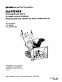
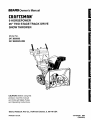
Owner's Manual
_.
|
CRAFTSMAN°
9 HORSEPOWER
26" TWO STAGE TRACK DRIVE
SNOW THROWER
Model No.
247.885690
247.88269CARB
CAUTION: Before using this
product, read this manual
and follow all Safety Rules
and Operating Instructions.
Sears,
Roebuck
Printed in U.S.A.
And
Co., Hoffman
Estates,
IL 60179
USA
770-0373M
8/96
(R960823)
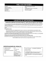
Warranty .....................................................................
2
Safe Operation Practices ............................................
3
Hardware Pack ...........................................................
5
Assembly ....................................................................
6
Operation ..................................................................
10
TWO YEAR LIMITED WARRANTY
Maintenance .............................................................
Service and Adjustments .........................................
Off-Season Storage .................................................
Trouble Shooting ......................................................
Repair Parts .............................................................
ON CRAFTSMAN
15
16
20
21
22
SNOW THROWER
For two years from the date of purchase, when this Craftsman Snow Thrower is maintained, lubricated and tuned
up according to the instructions in the owner's manual, Sears will repair, free of charge, any defect in material and
workmanship.
If this Craftsman snow thrower is used for commercial
from the date of purchase.
or rental purposes, this warranty applies for only 30 days
This warranty does not cover:
Expendable items which become worn during normal use, such as skid shoes, shave plate and spark plugs.
Repairs necessary because of operator abuse or negligence, including bent crankshafts and the failure to
maintain the equipment according to the instructions contained in the owner's manual.
WARRANTY SERVICE IS AVAILABLE BY RETURNING THE CRAFTSMAN SNOWTHROWERTOTHE
SEARS SERVICE CENTER/DEPARTMENT INTHE UNITED STATES.
NEAREST
This warranty applies only while this product is in use in the United States.
This warranty gives you specific legal rights, and you may also have other rights which may vary from state to state.
SEARS, ROEBUCK AND CO., D/817WA, HOFFMAN ESTATES, IL 60179
PRODUCT
SPECIFICATIONS
Horsepower:
9h.p.
Displacement:
19.43 cu.in.
Fuel Capacity:
4 quarts
Serial Number
Spark Plug
J-8C or equivalent
Date of Purchase
Engine
MODEL 143.979001
(247.885690)
MODEL 143.979007
(247.88269CARB)
Model Number
247.885690/247,88269CARB
The model and serial numbers will be found on a label
attached to the frame of the snow thrower.
You should record both serial number and date of purchase and keep in a safe place for future reference.
and/or
property
ofyourself
andothers.
Read
andfollowallinstructions
inthismanual
before
attempting
to
Thissymbol
operate
your
points
snowthrower.
outimportant
Failu
rsafety
etocomply
instructions
withthese
which,
instructions
ifnotfollowed,
mayresult
could
inpersonal
endanger
the
injury.
personal
safety
&
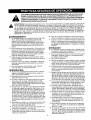
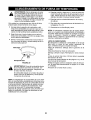
WARNING: This unit is equipped with an internal combustion engine and should not be used on or near any
unimproved forest-covered, brush-covered or grass-covered land unless the engine's exhaust system is equipped with
a spark arrester meeting applicable local or state laws (if any). If a spark arrester is used, it should be maintained in
effective working order by the operator. In the State of California the above is required by law (Section 4442 of the
California Public Resources Code). Other states may' have similar laws. Federal laws apply on federal lands. A spark
arrester for the muffler is available through your nearest Sears Authorized Service Center. (See the REPAIR PARTS
section of this manua!.)
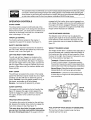
TRAINING
o
•
•
•
•
Read this owner's guide carefully in its entirety before
attempting to assemble or operate this machine. Be
completely familiar with the controls and the proper use
of this machine before operating it. Keep this manual in
a safe place for future and regular reference and for
ordering replacement parts.
Never allow children under 14 years old to operate a
snow thrower. Children 14 years old and over should
only operate snow thrower under close parental supervision. Only persons well acquainted with these rules of
safe operation should be al!owed to use your snow
thrower.
No one should operate this unit while intoxicated or while
taking medication that impairs the senses or reactions.
Keep the area of operation clear of all persons, especially small children and pets.
Exercise caution to avoid slipping or falling, especially
when operating in reverse.
PREPARATION
•
•
•
•
Thoroughly inspect the area where the equipment is to
be used and remove all door mats, sleds, boards, wires
and other foreign objects.
Do not operate equipment without wearing adequate
winter outer garments. De not wear jewelry, long scarfs or
other loose clothing which could become entangled in
moving pads. Wear footwear which will improve footing
on slippery surfaces.
Before working with gasoline, extinguish all cigarettes
and other sources of ignition. Check the fuel before
starting the engine, Gasoline is an extremely flammable
fuel. Do not fill the gasoline tank indoors, while the engine is running, or until engine has been allowed to cool
at least two minutes. Replace gasoline cap securely
and wipe off any spilled gasoline before starting the engine as it may cause a fire or explosion.
Use a grounded three wire plug-in for all units with electric
drive motors or electric starting motors.
•
Adjust collector housing height to clear gravel or crushed
rock surface.
e
Never attempt to make any adjustments while engine is
running (except where specifically recommended by
manufacturer).
Let engine and machine adjust to outdoor temperature
before starting to clear snow.
o
•
Always wear safety glasses or eye shields during operation or while perforrning an adjustment or repair, to
protect eyes from foreign objects that may be thrown
from the machine in any direction.
OPERATION
•
•
Do not put hands or feet near or under rotating parts.
Keep clear of discharge opening and auger at all times.
Exercise extreme caution when operating on or crossing
gravel drives, walk,% or roads. Stay alert for hidden
hazards or traffic.
•
Do not carry passengers.
•
After striking a foreign object, stop the engine, remove
wire from spark plug, and thoroughly inspect the snow
thrower for any damage. Repair the damage before
restarting and operating the snow thrower.
Ifthesnowthrowerstartstovibrateabnormally,
stopthe
engine and check immediately for the cause. Vibration is
generally a warning of trouble.
Stop engine whenever you leave the operating position,
before unclogging the collector/impeller housing or discharge guide, and making any repairs, adjustments, or
inspections. Never place your hand in the discharge or
collector openings. Use a stick or wooden broom handle
to unclog the discharge opening.
Take all possible precautions when leaving the unit unattended. Disengage the collector/impeller, stop the
engine, and remow_ the key.
When cleaning, repairing, or inspecting, make certain
collector/impeller and all moving parts have stopped.
Disconnect spark plug wire and keep away from plug to
prevent accidental starting,
Do not run engine indoors, exceptwhen starting engine
and transporting snow thrower in or out of building. Open
doors. Exhaust fumes are dangerous.
Do not clear snow across the face of slopes. Exercise
extreme caution when changing direction on slopes. Do
not attempt to clear steep slopes.
Never operate snow thrower without guards, plates, or
other safety protection devices in place.
•
•
•
•
•
•
•
•
Never operate snow thrower near glass enclosure, automobiles, window wells, drop off, etc., without proper adjustments of snow thrower discharge angle. Keep
children and pets away.
•
•
Do not overload machine capacity by attempting to clear
snow at too fast a rate. Never operate the machine at
high transport speeds on slippery surfaces. Look behind
and use care when backing.
Never direct discharge at bystanders or allow anyone in
front of unit.
•
Disengage power to collectodimpeller
or not in use.
•
Use only attachments and accessories approved by the
manufacturer of snow thrower (such as wheel weights,
counter weights, cabs, etc.).
•
•
•
•
when transporting
•
Never operate the snow thrower without good visibility or
light. Always be sure of your footing and keep a firm hold
on the handles. Walk, never run.
Muffler and engine become hot and can cause a burn.
Do not touch.
MAINTENANCE
•
•
Never store the machine with fuel in the fuel tank inside a
building where ignition sources are present, such as hot
water and space heaters, clothes dryers, and the like.
Allow engine to cool before storing in any enclosure.
Always refer to owner's guide instructions for important
details if snow thrower is to be stored for an extended
period.
Run machine a few minutes after throwing snow to
prevent freeze up of collectodimpeller.
Check clutch controls periodically to verify they engage
and disengage properly and readjust if necessary. Refer
to owner's guide for adjustment instructions.
&
WARNING:
The Engine Exhaust from
this product contains chemicals known
to the State of California to cause
cancer, birth defects or other
reproductive
harm.
AND STORAGE
Check shear bolts, engine mounting bolts, etc., at
frequent intervals for proper tightness to be sure equipment is in safe working condition.
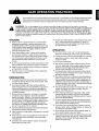
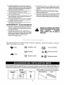
Look for this symbol to point out important safety precautions. It meansn
attention!!! Become alert!!! Your
safety is involved.
These symbols appear on your unit. Learn and understand their meaning, and follow them to ensure
safe operation of your Sears snow thrower.
Fast
_-_
Choke OFF
[]
Choke
B
Choke FULL
_
Ignition Key
._
_
Insert to run
Slow
_
_
Remove to stop
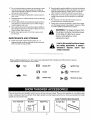
These accessories were available when the snow thrower was purchased. They are also available at most Sears retail
outlets, catalog and service centers. Most Sears stores can order repair parts for you, when you provide the model
number of your snow thrower.
ENGINE
SNOWTHROWER MAINTENANCE
Four Cycle
Oil
Gas Can
Spark Plug
Scraper Bar
Belt
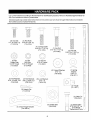
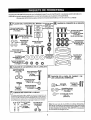
Lay out the hardware according to the illustration for identification purposes. Parts are illustrated approximately full
size. Part numbers are shown in parentheses.
(Hardware pack may contain extra items which are not used on your unit. A pair of auger shear bolts are provided in
the hardware pack as replacement parts.)
!i-.
!!.......
(8) Hex Bolt
1/4 - 20 x 3/4" Lg.
(710-3015)
(2) Hex Bolts
5/16-18 x 5/8" Lg.
(710-0118)
_
A
LF_
il
(4) Carriage Belts
5/16-18 x 1-1/2" Lg.
(710-1250)
(8) Rex
Flange Nuts
114-20 Thread
(712-3027)
(2) Hex
Lock Nuts
5/16-18 Thread
(712-0429)
(5) Hex Nut
5/16-18 Thread
(712-0267
(1) Hex Bolt
5/16-18 × 1-1/2" Lg
(710-0442)
_
_'/
(2) Hex Bolt
5/16-18 x 1-3/4" Lg.
(710-3180)
/
.>J
(1) Spring
Washer
5/16" I.D.
(736-0271)
(4) Cupped Washers
5!16" I.D.
(736-0242)
',\\_is
(2) Flat Washers
5/16" I.D.x5/8" O.D.
(736-0264)
(2) Flat Washers
3/8" I.D.x5/8" O.D.
(736-0140)
(5) Lock Washers
5/16" I.D.
(736-0119)
'>
(1) Ferrule
(711-0677)
(3) Hairpin Clip
(714-0104)
(2) Cable Tie
(725-0157)
!
_'"
(3) Chute Flange Keepers
(731-0851 A)
"--1
(2) Handle Tabs
(784-5599)
Fi-q
(2) Shear Bo,!ts*
5/16-18x1-1/2 Lg.
II ',1 (710-0890A)
*Replacement
Parts
IMPORTANT: This engine has been shipped without
gasoline or oil. After assembly, see operation section
of this manual for proper fuel and engine oil recommendations.
NOTE: To determine right and left hand sides of your
snow thrower, stand behind it in the normal operating
position.
Traction
Drive Control i_
Handle Panel
part numbers listed on page 5. Lay each hardware piece
on the picture and match the size.
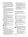
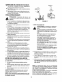
SETTING
UP YOUR
WARNING:
,_
SNOWTHROWER
Make certain the spark plug wire
is disconnected
and assembling
moved away the
fromsnow
the
spark
plug before
thrower.
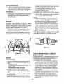
ATTACHINGTHE HANDLE ASSEMBLY
• Stretch out control cables and place on the floor.
Handles
Chute
i I
• Place right handle in position with flat side against
the snow thrower. You can identify the right handle
by the traction drive control label on it, and the left
handle by the auger clutch control label on it.
/i
//
//
/I
Chute
Crank
//
/ "'/_/
j<
'
S'd"' _1_
//
_
Shift
Rod
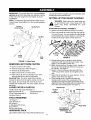
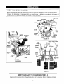
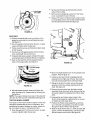
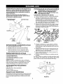
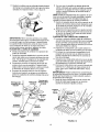
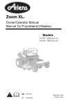
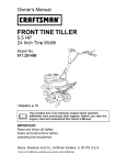
FIGURE 1: Loose Parts
REMOVING
UNIT FROM CARTON
• Cut the corners of the carton.
•
•
•
Remove loose parts. Refer to figure 1.
Remove all packing inserts.
Slide snow thrower out of the carton.
e Make certain all parts and literature have been
removed before the carton is discarded.
AssemblyTips:
For easier assembly purposes,
remove the chute from the carton and lay it on top of
the engine. Do not unwrap the chute till you have
installed the handle panel, the clutch cables, and the
belt cover.
LOOSE
PARTS IN CARTON
Handle Panel and Chute Assembly (1)
Right Hand Handle (1)
Left Hand Handle (1)
Chute Crank Assembly (1)
Shift Rod (1)
Hardware Pack (1)
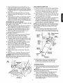
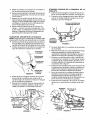
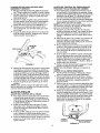
Bolt 113/4"
Long
FIGURE 2
• Secure bottom hole in handle to snow thrower
using 5/16 x 5/8" hex bolt and lock washer. See
figure 2. Do not tighten at this time.
• Match handle tab over the upper hole in handle, so
the curve in the handle tab matches the curve in
the handle. See figure 2.
• Secure to the snow thrower using hex bolt 5/16 x
1-3/4" long and lock washer. Do not tighten at this
time.
• Attach the left handle in the same manner. Do not
tighten at this time. See figure 2.
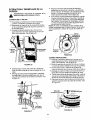
• Place handle panel in position between the
handles so the ends of the curved part of the
handles go through the slots in the handle panel.
Align the holes in the handle with the holes on the
two sides of the handle panel. See figure 3.
Right Handle
Handle Panel
Hex Bolt
and
Flange Nut
TOOLS REQUIRED
1/2" Wrench
7/16" Wrench (2)
3/8" Wrench
or Adjustable Wrenches
Pair of Pliers
Set of screw drivers
HARDWARE
PACK
Lay out the hardware according to the illustrations and
_Align
Carriage Bolt
Cu
and Hex Nut
FIGURE
3
Holes
•
•
Attach handle panel to the handle with four carriage bolts, cupped washers (cupped side against
the handle panel) and hex nuts as shown in figure
3. Align the contour of the carriage bolt head with
the handle.
Attach rear of handle panel with two 1/4-20 hex
bolts and flange nuts. See figure 3. Do not tighten
at this time.
• Tighten all loose hardware on the handle assembly
in the following order -- first the hex bolts at the
bottom of the handle, then the carriage bolts, and
lastly the hex bolts on the rear of the handle panel.
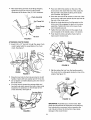
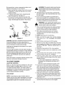
ATTACHING THE CLUTCH CABLES
The Z ends of the clutch cables are hooked into the
clutch grips on each handle.
= Lift the black plastic belt cover from the front of the engine (shipped loose in position). Refer to figure 4.
• Remove the two self-tapping screws from the engine frame that will be used to install the cover.
• Check and make sure that the cable is in the
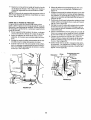
ATTACHING THE SHIFT ROD
•
•
Place the shift lever in the sixth (6) speed position.
Place the bent end of the shift rod into the hole in
the shift arm assembly. See figure 5. Secure with
spring washer, 5/16 flat washer and hairpin clip.
• Start threading the ferrule onto the other end of the
shift rod. Push down on the shift rod (and the shift
arm assembly) as far as it will go.
• Thread the ferrule onto the shift rod until the ferrule
lines up with the upper hole in the shift lever
(beneath the handle panel). Once the ferrule slides
into the hole, turn it counterclockwise one more full
turn and insert it in the hole in shift lever.
NOTE: It may be necessary to pull the shift lever out of
the sixth speed position and move it towards the fifth
speed position until the ferrule slides into the hole
without force.
• Insert the ferrule into the upper hole in the shift
lever from the right side when adjustment is correct. Secure with 5/16 flat washer and hairpin clip.
groove of the two cable guide rollers.
Attach cables as follows.
• Thread the hex nuts all the way up the threaded
portion of the Z ends of the clutch cables.
• Place the clutch grip in the raised (up) position.
• Thread the cable onto the threaded portion of the
Z until there is no slack in the cable, but the cable
is NOT tight. Do not overtighten cable.
= Squeeze the auger control lever against the handle
and make sure that the belts are tightening
• When correct adjustment is reached, tighten the
hex nut against the bottom portion of the cable to
lock it in position. Use pliers and 3/8" wrench to
lock the hex nut.
Shift
Lever
Traction
Drive
Clutch
Auger
Upper
Flat
Washer
Shift
Lever
Clip
Spring
Washer
;hift
Rod
• Tighten traction drive control cable in the same
manner.
• Place belt cover in position and secure with selftapping screws that you had earlier removed.
WARNING: If there is tension on the cable when the
clutch grip is released, the safety features of the snow
thrower may be overridden.
Chute Distance
Control
;hift Arm
Hair
Clip
Assembly
Flat
Washer
FIGURE
5
Make certain to check for correct adjustment of
the shift rod as instructed in the Adjustment
section before operating the snow thrower.
Belt
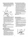
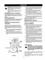
ATrACHING CHUTE
FIGURE 4
• Place chute assembly over chute opening, with the
opening in the chute assembly facing the front of
the unit.
NOTE: Make sure that the chute cables are straightened while assembling the chute.
• Place chute flange keeper (flat side down) beneath lip of chute assembly. See figure 6.
• Insert 1/4-20 hex bolt up through chute flange
keeper and chute assembly as shown in figure 6.
Do not tighten at this time. Rotate chute to install
all the flange keepers.
• After assembling all three chute flange keepers,
tighten then back off 1/4 turn to allow easier
movement of the chute. Use (2) 7/16" wrenches.
\
•
Place one 3/8 ID flat washer on the end of the
•
chute crank, then insert the end of the crank into
the eye hole in the plastic bushing in the chute
crank bracket. See figure 9.
Place the other 3/8 ID flat washer on the end of the
\
_.._Chute Assembly
Hex Flange Nut
Chute Flange
chute crank, and insert hairpin clip into eye hole at
the end of the chute crank.
• Adjust the chute bracket so that the spiral on the
chute crank fully engages the teeth on the chute
assembly. Tighten the nuts on the lower chute
crank bracket securely.
• Tighten the hex bolt and nut on the upper chute
crank bracket on the handle. Use a 1/2" wrench.
•
Bolt
Fully rotate the chute using the chute crank to
make sure it moves freely.
FIGURE 6
Flat
ATTACHING CHUTE CRANK
•
Insert 5/16 x 1/2" hex bolt through the upper chute
crank bracket which is assembled on the chute
crank. See figure 7.
Lock
j,_
_
Chute
Washer
Crank
\
\
Plastic
Bushing
FIGURE 9
Upper
Chute
Crank
Bracket
• Slip the cables that run from the handle panel to
the chute into the cable guide located on top of the
engine. See figure 10.
FIGURE 7
•
Place the hex bolt into the hole provided in the left
handle. Fasten with lock washer and 5/16 hex nut.
Cable
Guide
•
Do not tighten until after attaching the other end of
the chute crank.
• You may have to loosen the carriage bolts and
hex lock nuts which secure the lower chute crank
bracket to the extension on the left side of the
chute assembly. See figure 8.
Carriage Bolts &
r Hex Lock Nuts
FIGURE 10
Lower
Chute
Crank
FIGURE 8
IMPORTANT: Assemble your snow thrower, then
check the adjustments as instructed, and make any
final adjustments necessary before operating the
unit. Failure to follow the instructions may cause
damage to the snow thrower.
ATTACHING LEFT AND RIGHT TURN TRIGGERS
•
Remove the screw from the top of the right hand turn
trigger. Be careful not to lose the weld nut. Remove
the tdgger from the cable by pulling the cable out and
down. Slide cable barrel out of the slot.
• Make sure that the right hand trigger cable is routed in front of the traction drive cable.
TRACTION
DRIVE CONTROL ADJUSTMENT
• To check the adjustment ef the traction drive control and shift lever, move the weight transfer lever
to the transport position (see figure 16) and the
shift lever all the way forward to sixth (6) position.
• With the traction drive control released, pull the
triggers up to the handle and then push the snow
thrower forward to check that the tracks turn.
•
Slot
|ger
Squeeze traction drive control against the handle
and pull the starter. The tracks should turn.
• Now release the traction drive control and pull the
starter again. The unit should not move.
• Before proceeding with adjustment, checkto make
sure that the spark plug is disconnected,
• If the traction drive control needs adjustment,
loosen the jam nut on the traction drive cable and
thread the cable one turn. Recheck the adjustment
and repeat as necessary.
• Tighten the jam nut to secure the cable when correct adjustment is reached.
NOTE: For more details, refer to the Service and
Adjustment section.
Cable
FIGURE 11
•
•
•
•
•
•
Feed the trigger cable up through the outer side of the
slot in the plastic handle panel. De net feed the cable
through the same side of the slot as the Z fitting.
Slide and rotate the cable barrel into the slot on the
trigger. Pull the cable until it snaps into place.
Place the right turn trigger in position underneath
the right handle. Secure with screw just removed.
See figure 11. Use phillips screwdriver.
Secure the right turn trigger cable to the right lower
handle, using cable tie provided in the hardware
pack.
Secure the left turn trigger cable in the same
manner.
Trim excess ends from each cable tie.
NOTE: The right side cable tie must be used to keep
cable from coming in contact with the moving shift arm
from the transmission.
LAMP WIRING
• Wrap the wire from the lamp down the right handle. Plug wire into the alternator lead wire under
the fuel tank.
SKID SHOE ADJUSTMENT
The space between the shave plate and the ground
can be changed by adjusting the skid shoe.
• Return weight transfer lever to normal position before adjusting skid shoes.
• Forclosesnow removal, adjustskid shoes higherso
there is minimum gap between the shave plate and
the ground.
• For snow removal from uneven ground like gravel,
adjust skid shoes down so there is sufficient clearance between the bottom edge of shave plate and
the ground.
• Adjust skid shoes by loosening the four hex nuts
and carriage bolts, and moving skid shoes to desired position. Make certain the entire bottom surface of skid shoe is against the ground to avoid
uneven wear on the skid shoes. See figure 12.
• Retighten nuts and bolts securely.
FINAL ADJUSTMENTS
AUGER CONTROL ADJUSTMENT
• To check the adjustment of the auger control, push
forward on the left hand clutch grip until the rubber
bumper is compressed. There should be slack in
the clutch cable.
• Release the clutch grip. The cable should be
straight. Make certain you can depress the auger
control grip against the left handle completely.
• If necessary, loosen the hex jam nut and thread the
cable in (for less slack) or out (for more slack).
• Recheck the adjustment. Tighten the jam nut against
the cable when correct adjustment is reached.
Skid
Shoe
FIGURE
Hex Nuts
Carriage Bolts
12
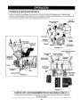
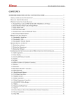
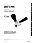
KNOW YOUR SNOW THROWER
READ THIS OWNER'S MANUAL AND SAFETY RULES BEFORE OPERATING YOUR SNOW THROWER.
Compare the illustrations in this manual with your snow thrower to familiarize yourself with the location of
various controls and adjustments. Save this manual for future reference.
Fuel Cap
Spark PlugOil F_I Plug
Choke
Muffler
Fuel
Tank
Ig
Key
Chute
Discharge
CI lute
Handle
Recoil
Primer
Throttle
FIGURE 14
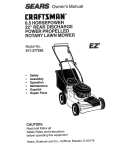
Traction Drive Control
Auger
Control
Wire
Control
Chute Distance
Left Turn
Trigger
Weight
Transfer
Lever
Shift Lever
Chute
Crank
Au(
Housing
Auger
Rig ht Turn
Trigger
Skid Shoe
FIGURE 13
FIGURE 15
MEETS
ANSI
SAFETY
REQUIREMENTS
B71.3
Sears snow throwers conform to the safety standards of the American National Standards Institute.
10
The operation of any snow thrower can result in foreign objects being thrown into the eyes, which I
can result in severe eye damage. Always wear safety glasses or eye shields while operating the '
snow thrower or performing any adjustments or repairs. We recommend standard safety glasses
or wide vision safety mask for over you r glasses available at SEARS retail stores.
_
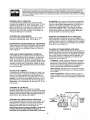
OPERATION
CONTROLS
engaged with the traction drive control engaged, you
can release the auger control (on the left handle) and
the augers will remain engaged. Release the traction
drive control to stop both the augers and wheel drive.
(Auger control must also be released).
CHUTE CRANK
The chute crank is located on left hand side of the
snow thrower. See figure 13.To change the direction in
which snow is thrown, turn chute crank as follows: turn
clockwise to discharge to the left; turn counterclockwise to discharge to the right.
CHUTE DISTANCE CONTROL
The distance snow is thrown can be adjusted by
adjusting the angle of the chute assembly. Move the
chute distance control forward to decrease the distance, toward the rear to increase the distance. See
figure 15.
THROTTLE CONTROL
The throttle control is located on the engine. It
regulates the speed of the engine. See figure 14.
SAFETY IGNITION SWITCH
The ignition key must be inserted into the switch for
the unit to start. Remove the ignition key when snow
thrower is not in use. See figure 14.
WEIGHT TRANSFER
LEVER
The weight transfer lever is located on the right side of
the snow thrower and is used to select the position of
the housing and the method of track operation. Move
the lever to the right, then forward or backward to one
of the three positions. See figure 16.
LEFT AND RIGHT TURN TRIGGER
The left and right turn triggers are located on the
underside of the handles and are used to assist in
steering your snow thrower. See figure 15. Squeeze
the right turn trigger when turning right, squeeze the
left turn trigger when turning left. Operate your snow
thrower in open areas until you become familiar with
these controls.
Transport--Raises
the front end of the snow
th rower for easy transport. Using proper caution,
this position may also be used on many gravel driveways to clear snow while leaving gravel undisturbed.
Normal Snow--Allows the tracks to be suspended
independently for continuous ground contact.
SHIFT LEVER
Packed Snow--Locks
The shift lever is located in the center of the handle
the front end of the snow
th rower down to the ground for hard-packed or icy
snow conditions.
panel. The shift lever may be moved into one of eight
positions. Use the shift lever to determine ground
speed. Forward---one of six speeds; position one (1) is
the slowest and position six (6) is the fastest.
Reverse--two reverse (R) speeds; R2 is faster.
Position
AUGER CONTROL
Normal
Snow
The auger control is located on the left handle. See
figure 15. Squeeze the auger control against the
handle to engage the augers; release to disengage
the augers. (Traction drive control must also be
released.)
Position
TRACTION DRIVE CONTROL
FIGURE 16
The traction drive control is located on the right handle. Squeeze the traction drive control to engage the
track drive; release to stop. See figure 15.
FUEL SHUT-OFF VALVE (Model 247.88569GARB)
This same lever also locks the auger control so
you can turn the chute crank without interrupting
the snow throwing process. If the auger control is
The fuel shut-off valve, located under fuel tank,
controls fuel flow from tank.
11
TO STOP THE SNOW THROWER
•
• To stop the track, release the traction drive lever.
• When clearing your first pass through the snow,
control the traction speed of the snow thrower according to the depth and condition of the snow.
• To stop throwing snow, release the auger drive lever.
• To stop the engine, push the throttle control lever to
OFF and pull out the ignition key. Do not turn key.
OPERATING
• To turn the unit ]eft squeeze left trigger; to turn r!ght
squeeze right trigger.
• On each succeeding pass, readjust the chute deflector to the desired position and slightly overlap
the previously cleared path.
THE SNOW THROWER
TO ENGAGE DRIVE
•
With the engine running near top speed, move shift
lever into one of six FORWARD positions or two
REVERSE positions. Select a speed appropriate
for the snow conditions that exist. Use slower
speeds until you are familiar with the operation of
the snow thrower.
•
Squeeze the traction drive clutch grip against the
right handle and the snow thrower will move. Release it and the drive motion will stop.
• After the area is cleared, stop the snow thrower following preceding instructions.
BEFORE
ENGINE
engine oil only.
FILL OIL
•
To engage the augers and start snow throwing,
squeeze the left hand auger clutch grip against the
left handle. Release to stop augers.
• While the left handle auger control is engaged,
squeeze the right hand traction drive control to
move, release to stop. Do not shift speeds while
drive is engaged.
NOTE: This same lever also locks the auger control so
you can turn the chute crank without interrupting the
snow throwing process.
•
STARTING
Only use high quality detergent oil rated with API
service classification SF or SG. Use SAE 5W30
TO ENGAGE AUGERS
•
Interlock feature will allow you to remove your left
hand from the auger control lever.
This snow thrower was shipped with a container of
5W30 oil. This oil must be added to the engine before
starting.
NOTE: In areas where temperature is consistently at
20 ° F or lower, you may use OW30 motor oil for easier
starting.
• Remove the oil fill cap!dipstick.
•
Release the left hand auger control; the interlock
mechanism should keep the left hand auger control engaged until the right hand traction drive control is released.
•
Pour the oil and fill the crankcase to line (Full) on
dipstick (19 ounces). See figure 17.
Tighten the oil fill cap/dipstick securely.
NOTE: Engine may already contain some residual oil.
Check frequently when filling the crankcase. Do not
overfill.
Release the traction drive control to stop both the
augers and the wheel drive.
WARNING: To stop auger both levers must be
NOTE: Oi! must be changed after the first two (2)
hours of operation to extend engine life.
released.
Never move shift lever without first releasing
the drive clutch.
FILL GAS
WARNING: Gasoline is flammable and cau-
TO THROW SNOW
Do not
tion
must
fill be
fuelused
tankwhen
while handling
snow thrower
or storing
is runit.
ning, when it is hot or when snow thrower is
in an enclosed area.
CAUTION: Check the area to be cleared for foreign
objects. Remove, if any.
• Move weight transfer lever to the right, then backward or forward to the desired position.
• Start the engine following Starting Instructions.
•
•
•
Keep away from open flame or an electrical
spark and do not smoke while filling the fuel
tank.
Never fill the fuel tank completely. Fill the
tank to within 1/4"-1/2" from the top to provide space for expansion of fuel.
Rotate the discharge chute to the desired direction,
away from bystanders and/or buildings. Move the
chute distance control forward or backward to adjust the distance the snow is to be thrown.
Select the speed according to the snow condition.
Always fill fuel tank outdoors and use a funnel or spout to prevent spilling.
Make sure to wipe up any spilled fuel before starting
the engine.
Engage the auger control and traction drive control
levers following the preceding instructions.
12
Storegasolineina clean,approvedcontainer,and
keepthecapinplaceonthecontainer.
• Make sure that the container from which you pour
the gasoline is clean and free from rust or other
foreign particles.
• Fill fuel tank with clean, fresh, unleaded grade
automotive gasoline. See figure 17.
• At the end of the job, empty the fuel tank if the
snow thrower is not going to be used for 30 days or
longer. See Storage instructions in this manual.
•
WARNING: The electric starter must be properly grounded at all times to avoid the possibility of electric shock which may be injurious
to the operator.
Determine that your house wiring is a three-wire
grounded system. Ask a licensed electrician if you
are not certain.
• If your house wiring system is grounded and a
three-hole receptacle is not available at the point
the snow thrower starter will normally be used, one
should be installed by a licensed electrician.
Gasoline
WARNING:
If your house wiring system is not
a three-wire grounded system, do not use this
electric starter under any conditions.
OIL
• When connecting the power cord, always connect
cord to starter on engine first, then plug the other
end into a three-hole grounded receptacle.
• When disconnecting the power cord, always
unplug the end from the three-hole grounded
receptacle first.
• Attach spark plug wire to spark plug.
• Make sure that the auger drive and the traction
drive levers are in the disengaged RELEASED
position.
FIGURE 17
CAUTION: Experience indicates that alcohol blended
fuels (called gasohol) or those using ethanol or
methanol can attract moisture which leads to separation and formation of acids during storage.
• Move throttle control lever to FAST position.
Acidic gas can damage the fuel system of an engine
while in storage.
To avoid engine problems, the fuel system should be
emptied before storage for 30 days or longer. Drain the
gas tank, start the engine and let it run until the fuel
lines and carburetor are empty. Use fresh fuel next
season. See STORAGE Instructions for additional
information.
•
Remove the keys from the plastic bag. Push key
into the ignition slot. Make sure it snaps into place.
DO NOT TURN KEY. Keep the second key in a
safe place.
•
Rotate the choke knob to FULL choke position.
• Connect the power cord to the switch box on the
engine.
•
Plug the other end of the power cord into a threehole, grounded 120 volt A.C. receptacle.
•
Push the primer button while covering the vent
hole as follows: (Remove finger from primer button
between primes.)
Do not prime if temperature is above 50 ° E
Prime two times if temperature is between 50 ° F
and 15° E
Never use engine or carburetor cleaner products in the
fuel tank or permanent damage may occur.
TO START
ENGINE
(ELECTRIC STARTER)
Make sure that the engine has sufficient oil. The snow
thrower engine is equipped with a 120 volt A.C. electric starter and recoil starter. The electric starter is
•
Prime four times if temperature is below 15° E
Push down on the starter button until the engine
starts. Do not crank for more than 10 seconds at a
time. This electric starter is thermally protected. If
overheated, it will stop automatically and can be
restarted only when it has cooled to a safe temperature (a wait of about 5 to 10 minutes is required).
• When the engine starts, release the starter button
and slowly rotate the choke to OFF position. If the
engine falters, rotate the choke to FULL and then
gradually to OFF.
• Disconnect the power cord from the receptacle first
and then from the switch box on the engine.
equipped with a three-wire power cord and plug, and
is designed to operate on 120 volt AC household
current. Follow all instructions carefully.
COLD START
NOTE: tf unit shows any sign of motion (drive or
augers) with the clutch grips disengaged, shut engine
off immediately. Readjust as instructed in the "Final
Adjustments" section of the Assembly Instructions.
13
• Allowtheenginetowarmupfora fewminutesbecausetheenginewillnotdevelopfullpoweruntilit
reachesoperating
temperature.
• Operatetheengineatfullthrottle(FAST)when
throwingsnow.
WARM START
•
FROZEN
WARM START
•
•
STARTER
Pull as much rope out of the starter as possible.
•
Release the starter handle and let it snap back
against the starter.
• If the engine still fails to start, repeat the first two
steps. If continued attempts do not free starter,
follow the electric starter procedures to start.
Avoid possible freezing of recoil starter and the engine
controls.
(R ECOI L STARTER)
Make sure that the engine has sufficient oil and the
auger drive and the traction drive levers are disengaged (released).
• Move throttle control to FAST position.
•
RECOIL
If the starter is frozen and will not turn the engine, proceed as follows:
If restarting a warm engine after a shut down, rotate choke to OFF instead of FULL and do not
push the primer button.
TO START ENGINE
•
If restarting a warm engine after a shut down, rotate choke to OFF instead of FULL and do not
push the primer button.
OPERATING
Push key into the ignition slot and make sure that it
snaps into place. Do not turn key. Remove plastic
bag and keep the second key in a safe place.
Rotate choke control to FULL choke position.
TIPS
NOTE: Allow the engine to warm up for a few minutes
as the engine will not develop full power until it
reaches operating temperature.
Warning: Temperature of muffler and surrounding
areas may exceed 150 ° F. Avoid these areas.
•
Push the primer button while covering the vent hole.
Remove finger from primer button between primes.
Do not prime if temperature is above 50 ° R
Prime two times in temperatures between 50 ° F
and 15 ° E
Prime four times in temperatures below 15° E
• Pull the starter handle rapidly. Do not allow the
handle to snap back, but allow it to rewind slowly
while keeping a firm hold on the starter handle.
• As the engine warms up and begins to operate
evenly, rotate the choke knob slowly to OFF position. if the engine falters, return to FULL choke,
then slowly move to OFF choke position.
• Allow the engine to warm up for a few minutes because the engine will not develop full power until it
reaches operating temperature.
• Operate the engine at full throttle (FAST) when
throwing snow.
•
For most efficient snow removal, remove snow
immediately after it falls.
• Discharge snow downwind whenever possible.
Slightly overlap each previous swath.
• Set the skid shoes 1/4" below the scraper bar for
normal usage. The skid shoes may be adjusted
upward for hard-packed snow. Adjust downward
when using on gravel or crushed rock.
• Follow the precautions listed under "To Stop
Engine" and "Frozen Recoil Starter" in previous
sections to prevent possible freeze-up.
• Clean the snow thrower thoroughly after each use.
14
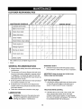
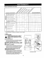
CUSTOMER
RESPONSIBILITIES
MAINTENANCE
SCHEDULE
/
<<" y
_ J" _"_ Y '_"_/
SERVICE DATES*
Lubricate pivot points
J
Clean snow thrower
%/
J
%/
I-
O
Clean shave plate
Q
O
Clean skid shoes
a.
%/
Check V-Belts
Check friction wheel rubber
Check engine oil
%/
J
Change engine oil
%/
%/
W
Z
Service air cleaner
%/
Z
u.I
Check spark plug
J
Check muffler
%/
%/
Fill in dates as you complete regular service
_/ Check
GENERAL
SPROCKET SHAFT
RECOMMENDATIONS
•
• Always observe safety rules when performing any
maintenance.
• The warranty on this snow thrower does not cover
items that have been subjected to operator abuse
or negligence. To receive full value from the warranty, operator must maintain the snow thrower as
instructed in this manual.
IMPORTANT: Keep all grease and oil off of the
friction wheel and drive plate.
SHIFTING MECHANISM
= Some adjustments will need to be made periodically to properly maintain your unit.
= Lubricate the shifting mechanism and pivot points
on the shift rod with engine oil at least once a
season or after every 25 hours of operation.
• All adjustments in the Service and Adjustments
section of this manual should be checked at least
once each season.
•
Lubricate the sprocket shaft with grease at least
once a season or after every 25 hours of operation.
Follow the maintenance schedule on this page.
TRACTION DRIVE CONTROL
Lubricate cams on the ends of the control rods
which interlock the traction drive and auger
controls at least once a.season or every twentyfive hours of operation with grease. The cams can
be accessed beneath the handle panel.
LUBRICATION
WARNING: Disconnect the spark plug wire
and ground against the engine before performing any repairs or maintenance.
15
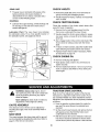
CHECK V-BELTS
GEAR CASE
• The gear case is lubricated with grease at the
factory and does not require checking. If
disassembled for any reason, lubricate with 2
ounces of Shell Alvania grease.
•
Remove the plastic belt cover on the front of the engine by removing two self-tapping screws.
• Visually inspect for frayed, cracked, or excessively
worn out belts.
BEARINGS
CHECK
• Lubricate the auger bearings, wheel bearings and
the bearings on the side of the frame once a
season with light oil.
FRICTION
WHEEL
Check the condition of the friction wheel rubber after
every 25 hours of operation.
• Remove the four self-tapping screws from the
frame cover underneath the snow thrower.
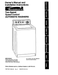
Lubrication Chart: The view shown here indicates
the lubrication points. For a more specific location of
the lubrication points, see pages 22 and 23.
• Visually inspect the friction wheel rubber for excessive wear, cracks, or loose fit on the friction wheel
drive hub.
• Also, engage traction drive control and check if the
friction wheel is making contact with the friction
plate.
• If it does not make contact, adjust the traction drive
cable following instructions below and recheck.
• Replace friction wheel rubber if necessary. Refer
to instructions on page 19.
CHECK
ENGINE OIL
• Remove oil fill plug and dipstick.
• Wipe dipstick clean, insert it into oil fill hole and
tighten securely.
• Remove dipstick and check. If oil is not up to FULL
mark on dipstick, add 5W30 oil. Pour slowly and
check again.
_,
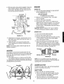
TRACTION
WARNING: Always stop engine, disconnect spark plug wire, and move it away from
spark plug before performing any adjustments or repairs.
Refer to the Final Adjustment section of the Set-Up
Instructions to adjust the traction drive control. If you
are uncertain whether you have reached the correct
adjustment, the adjustment can be physically checked
as follows.
Never attempt to clean chute or make any
adjustments while engine is running.
CHUTE
•
Drain the gasoline or place plastic film under the
gas cap if the snow thrower has already been
operated.
• Tip the snow thrower forward, and remove the four
self-tapping screws that hold the frame cover
underneath the snow thrower.
ASSEMBLY
The distance snow is thrown can be adjusted by
adjusting the angle of the chute assembly. Refer to
page 11.
SKID
DRIVE CONTROL
SHOE
• With the traction drive control released, make sure
that there is clearance between the friction wheel
and the friction plate in all positions of the shift lever.
The space between the shave plate and the ground
can be adjusted by adjusting the skid shoe. Refer to
page 5 of the Set-Up Instructions.
16
ENGINE
Withthetractiondrivecontrolengaged,
make sure
that the friction wheel is making contact with the
friction plate. See figure 18. Also make sure that
the overtravel spring is stretched.
ENGINE OIL
•
Only use high quality detergent oil rated with API
service classification SF or SG.
Use 5W-30 oil. only.
OiJsump capacity:
1-1/4 pints/19 ounces/.56 liter
• Maintain oil level between "FULL" and "ADD"
Drive Shaft
Drive
Sprocket
Shaft
marks on dipstick.
Remove oil fill plug and dipstick.
•
• Wipe dipstick clean, insert it into oil fill hole and
tighten securely. Remove dipstick. If oil is not up to
"FULL" mark on dipstick, add recommended oil.
POUR SLOWLY. Wipe dipstick clean each time oil
level is checked.
Important: Do not fill above "full" mark on dipstick.
• Install oil fill plug and dipstick, tighten securely.
Pivot
Rod
Wheel
tion
Plate
SPARK PLUG
• Clean area around spark plug base.
FIGURE 18
•
If adjustment is necessary, loosen the jam nut on
the traction drive cable and thread the cable in or
out as necessary.
•
Remove and inspect spark plug.
•
Replace spark plug if electrodes are pitted, burned,
or the porcelain is cracked. For further details,
refer to the engine manual.
Clean the spark plug and reset the gap .030" at
least once a season or every 50 hours of operation. Spark plug replacement is recommended at
the start of each season. Refer to engine parts list
for correct spark plug type. See figure 20.
•
• Tighten the jam nut to secure the cable when
correct adjustment is reached. Reassemble the
frame cover.
NOTE: If you ptaced plastic under the gas cap, be
certain to remove it.
Electrodes
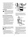
AUGERS
The augers are secured to the spiral shaft with two
shear bolts and hex lock nuts. If you hit a foreign object
or ice jam, the snow thrower is designed so that the
bolts will shear.
.030 Gal:
FIGURE 20
•
If the augers will not turn, check to see if the bolts
have sheared. Replace if necessary. See figure 19.
Two replacement hex bolts and hex lock nuts have been
provided with the snow thrower.
NOTE: Do not sandblast spark ptug. Spark ptug
should be cleaned by scraping or wire brushing and
washing with a commercial solvent.
AUGER CLUTCH
Auger Bolts
To adjust the auger clutch, refer to Final Adjustment
section of Assembly Instructions.
SHIFT ROD
To adjust the shift rod, proceed as follows.
• Remove the hairpin clip and flat washer from the
ferrule underneath the shift panel. Remove the
ferrule from the hole in the shift lever.
•
FIGURE 19
17
Place the shift lever on the handle panel in the
sixth (6) speed position (all the way forward).
• Pushdownontheshiftrod(andshiftarmassembly)asfarasitwillgo.Holditinthisposition.
• Threadtheferruleupordowntheshiftrodas
necessaryuntiltheferrulelinesupwiththeupper
holeintheshiftlever.Refertofigure9.
• Insertferruleintotheupperholeintheshiftlever
fromtherightsidewhenadjustment
is correct,
Securewithflatwasherandhairpinclip.
• Beforeoperatingthesnowthrower,checkforcorrectadjustment
ofthetractiondrivecontrolasinstructedintheFinalAdjustment
section.
Self-Tapping
Screws
Cover
CARBURETOR
&
WARNING: If any adjustments are made to
the engine while the engine is running (e.g.
carburetor), keep clear of all moving parts.
Be careful of heated surfaces and muffler.
/
FIGURE 21
If you think your carburetor needs adjusting,
see your nearest authorized Tecumseh
Service Outlet.
•
•
Unthread the bottom of the auger cable from the
top of the cable, leaving the hex nut in place.
Remove the six lock washers and hex nuts which
attach the auger housing assembly to the frame.
See figure 22.
SHAVE PLATE AND SKID SHOES
The shave plate and skid shoes on the bottom of the
snow thrower are subject to wear. They should be
checked periodically and replaced when necessary.
• To remove skid shoes, remove the four carriage
bolts, belleville washers and hex nuts which attach
them to the snow thrower.
I
•
Reassemble new skid shoes with the four carriage
bolts, belleville washers (cupped side goes against
skid shoes) and hex nuts. Make certain the skid
shoes are adjusted to be level.
• To remove shave plate, remove the carriage bolts,
belleville washers and hex nuts which attach it to
the snow thrower housing. Reassemble new
shave plate, making sure heads of the carriage
bolts are to the inside of the housing. Tighten
securely.
, LockWashers
Hex Nuts
Franle
Auger
Assembly
FIGURE 22
BELT REMOVAL
_lb
AND REPLACEMENT
•
Separate the housing from the frame assembly by
standing in the operating position and lifting up on
the handles. The frame and housing will separate,
and the rear auger drive belt will come off the
pulleys. See figure 23.
• To remove the front auger drive belt, push the idler
pulley to the left, and lift front auger drive belt from
the front auger pulley. See figure 23. Replace both
auger drive belts by following the preceding
instructions.
NOTE: When reassembling the two halves of the unit,
make sure that the auger drive cable is routed through
the cable roller guide.
from
ARNING:
the sparkDisconnect
plug and ground.
the spark plug wire
AUGER BELTS
• To remove and replace either the rear or front
auger drive belt, proceed as follows.
• Disconnect the chute crank at the chute assembly
by removing the cotter pin and flat washer.
• Remove the plastic belt cover on the front of the
engine by removing two self-tapping screws. See
figure 21.
18
• Tip the snow thrower up and forward, so that it
Front Auger
Drive Belt
•
•
rests on the housing.
Remove four self-tapping screws from the frame
cover underneath the snow thrower.
Using a 7/8" wrench to hold the shaft, loosen, but do
not completely remove, the hex bolt and bell washer
from the left end of the shaft. See figure 25.
Pulley
FIGURE 23
DRIVE BELT
•
Remove the plastic belt cover on the front of the
engine by removing the two self-tapping screws.
See figure 21.
• Drain the gasoline from the snow thrower, or place
a piece of plastic under the gas cap.
• Tip the snow thrower up and forward so that it rests
on the housing.
• Remove four self-tapping screws from the frame
cover underneath the snow thrower.
•
•
Hex Bolt
BellWasher
Pulling the idler pulley upward, roll belt off the idler
and engine pulleys and lift belt off friction wheel disc.
Back out the stop bolt until the support bracket
rests on the auger pulley. See figure 24.
Track
FIGURE 25
\
Move the weight transfer lever to the packed snow
position. Refer to figure 16.
Lightly tap the head of bolt to dislodge the ball
bearing from the right side of frame, then remove
hex bolt and bell washer from left end of shaft.
o
FIGURE 24
Sliding the shaft to the right, remove the spacer,
sprocket, and friction wheel assembly from the
shaft. See figure 26.
Remove the six screws from the friction wheel
•
Slip belt between friction wheel and friction disc
plate. See figure 24. Reassemble by following the
instructions.
NOTE: The support bracket must rest on the stop bolt
after the new belt has been assembled. See figure 24.
assembly (three from each side). Remove the friction wheel rubber from between the friction wheel
plate.
Reassemble new friction wheel rubber to the
friction wheel assembly, tightening the six screws
in rotation and with equal force.
Position the friction wheel assembly up onto the
pin of the shift rod assembly, and slide the shaft
through the friction wheel. See figure 26.
Slide the shaft into the hex I.D. of the sprocket, the
spacer, and the left ball bearing, and secure with
the bell washer and hex bolt. See figure 26.
FRICTION WHEEL RUBBER
The rubber on the friction wheel is subject to wear and
should be checked after 25 hours of operation, and
periodically thereafter. Replace the friction wheel rubber if any signs of wear or cracking are found.
• Drain the gasoline from the snow thrower, or place
a piece of plastic under the gas cap.
19
Spacer
Sprocket
Shift Rod
Assembly
Friction Wheel
Assembly
FIGURE 26
NOTE: Do not drain carburetor if using fuel stabilizer.
Never use engine or carburetor cleaning products in
the fuel tank or permanent damage may occur,
WARNING: Never store engine with fuel in
tank indoors or in poorly ventilated areas,
where fuel fumes may reach an open flame,
spark or pilot light as on a furnace, water
heater, clothes dryer or gas appliances.
WARNING: Drain fuel into approved container outdoors, away from open flame. Be
certain engine is cool. Do not smoke.
It is important to prevent gum deposits from forming in
essential fuel system parts such as the carburetor, fuel
filter, fuel hose or tank during storage.
Fuel left in engine during warm weather deteriorates and will cause serious starting problems.
Also experience indicates that alcohol blended fuels
(called gasohol or using ethanol or methanol) can
attract moisture which leads to separation and formation of acids during storage. Acidic gas can damage
the fuel system of an engine while in storage.
NOTE: Fuel stabilizer (such as STA-BIL) is an acceptable alternative in minimizing the formation of fuel gum
deposits during storage, Add stabilizer to gasoline in
fuel tank or storage container. Always follow mix ratio
found on stabilizer container. Run engine at least 10
minutes after adding stabilizer to allow it to reach carburetor, Do not drain carburetor if using fuel stabilizer.
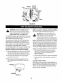
To avoid engine problems, the fuel system should be emptied before storage for 30 days or longer. Follow these
instructions to prepare your snow thrower for storage:
•
Remove all gasoline from carburetor and fuel tank
to prevent gum deposits from forming on these
parts and causing possible malfunction of engine.
•
Run engine until fuel tank is empty and engine
stops due to lack of fuel.
•
•
Remove spark plug and pour one (1) ounce of
engine oil through spark plug hole into cylinder.
Crank engine several times to distribute oil.
Replace spark plug.
• Remove all dirt from exterior of engine and equipment.
Drain carburetor by pressing upward on bowl
drain, located below the carburetor cover. See
figure 27.
•
Follow lubrication recommendations
and 16.
•
Store in a clean, dry area.
on pages 15
NOTE: When storing any type of power equipment in
an unventilated or metal storage shed, care should be
taken to rust proof the equipment. Using a light oil or
silicone, coat the equipment, especially any chains,
springs, bearings and cables.
Carburet__
Bowl Drain
FIGURE 27
2O
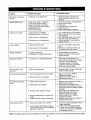
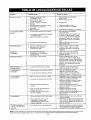
Trouble
Possible Cause(s)
Corrective
Shift lever not locking
into 6th
1. Shift rod out of adjustment.
1. Remove washer and pin.Turn
ferrule clockwise one turn and
reinstall,
Engine fails to start
1.
2.
3.
4.
5.
6,
1.
2.
3.
4,
5.
6.
Engine runs erratic
1. Unit running on CHOKE.
2. Blocked fuel line or stale fuel.
Fuel tank empty, or stale fuel.
Fuel shut-off valve closed.
Key not in switch on engine.
Spark plug wire disconnected.
Blocked fuel line.
Faulty spark plug.
3. Water or dirt in fuel system.
4. Carburetor out of adjustment.
Loss of power
1. Spark plug wire loose.
2. Gas cap vent hole plugged.
Action
Fill tank with clean, fresh gasoline.
Open shut-off valve.
Insert key.
Connect wire to spark plug.
Clean fuel line.
Clean, adjust gap or replace.
1, Turn choke knob to OFF position.
2. Clean fuel line; fill tank with clean
fresh gasoline.
3. Use carburetor bowl drain to drain
fuel tank. Refill with fresh fuel.
4. Adjust carburetor. See separate
engine manual.
1. Connect and tighten spark plug
wire.
2. Remove ice and snow from cap.
Be certain vent hole is clear.
1. Fill crankcase with proper oil.
2. Adjust carburetor. See separate
engine manual.
Engine overheats
1. Engine oil level low.
2, Carburetor not adjusted properly.
Excessive vibration
1. Loose parts or damaged impeller.
Hard to shift, or will
not shift
1. Shift rod misadjusted.
1. Readjust shift rod. See Adjustment
section of this manual.
Unit fails to propel itself
1. Incorrect adjustment of drive clutch.
1. Adjust drive clutch. Refer to
Adjustment section.
2. Replace drive belt. Refer to
Maintenance section.
2. Drive belt loose or damaged,
Unit fails to discharge
1. Auger shear bolt broken.
snow
2. Discharge chute clogged.
3. Foreign object lodged in auger,
4. Incorrect adjustment of auger drive
clutch.
5. Auger drive belt loose or damaged.
Track does not turn
1. Track control cable not inserted.
2. Lower cable bracket (#52 on page
24 for reference) not fully positioned
against the gear box.
Stop engine immediately and
disconnect spark plug wire. Tighten
all bolts and nuts. Make all
necessary repairs. If vibration
continues, have unit serviced by
authorized service dealer.
1. Replace auger shear bolt. Refer to
Maintenance section.
2. Stop engine immediately and
disconnect spark plug wire. Clean
discharge chute and inside of auger
housing.
3. Stop engine immediately and
disconnect spark plug wire.
Remove object from auger.
4. Adjust auger clutch. Refer to
Adjustment section.
5. Replace auger drive belt. Refer to
Maintenance section.
Insert the cable completely into the
trigger assembly.
2. Loosen two self-tapping screws
on each slot of bracket. Retighten
making sure the bolt is completely
in the bottom of slot.
.
NOTE: For repairs beyond the minor adjustments listed above, please contact your nearest authorized service dealer.
21
i /
//
//
/
,
/
I
il
/ i
i
/
/
/
/
/
22
/
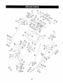
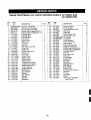
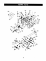
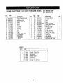
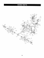
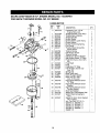
SEARS CRAFTSMAN
{EY
NO.
1
2
3
4
5
6
7
8
9
10
11
12
13
14
15
16
17
18
19
20
21
22
23
24
25
26
27
28
29
30
31
32
33
34
35
PART
NO.
9 H.P. SNOW THROWER
DESCRIPTION
684-0008-0637 Shift Arm Assembly
684-0022
Chute Crank Assembly
684-0032A
Handle Panel Assembly
684-0112
Handle Assy. Engagement RH
384-0111
Handle Assy. Engagement LH
710-1250
Carriage Bolt
710-0262
Carriage Bolt
710-0451
Carriage Bolt
710-0896
Hex Screw
710-1003
Tapp. Screw
711-0653
Clevis Pin
712-0116
Lock Nut
712-0267
Hex Nut
Hex Patch Lock Nut
712-3068
Cotter Pin
714-0507
715-0138
Rolling Pin
Chute Crank Knob
720-0201A
720-0300
Shift Knob
726-0100
Push Cap
731-1300A
Lower Chute
Cable Guide
731-1313B
731-1320
Upper Chute
731-1773
Handle Panel
732-0145
Compression Spring
732-0193
i Compression Spring
732-0705
Cable Control Wire
732-0746
Torsion Spring
735-0199A
Rubber Bumper
736-0105
Bell Washer
736-0119
Lock Washer
736-0231
Washer
Bell Washer
736-0242
Washer
736-0506
736-0509
Washer
737-0133
Plastilube
QTY.
1
1
11
1
4
1
1
I KEY I
I NO, i
!
_
1
MODELS
247.885690 AND
247.88269CARB
PART
NO.
DESCRIPTION
741-0475
37 746-0896
38 746-0901
361,
39 747-0798A
40 747-0877
41 748-0362
42 748-0363
43 749_908A-0637
749-0909-0637
44
784-5594
45
46 784-5604
784-5619
48 784-5679
49 784-5680
5O 784-5681
784-5682
51
736-0242
52
712-0267
53
54
712-3027
55
710-0442
56
736-0119
57 784-5599
58i 710-3180
59 _ 710-3025
601 736-0271
61 736-0264
62 736-0140
63 714-0104
64 731-0851A
65 710-3015
66 711-0677
67 725-1300
68 731-1317
69 629-0058
Plastic Bushing
Control Cable
Chute Deflector Cable
Shift Rod
CAM Rod
CAM Handle Lock
Pawl Handle Lock
RH Handle
LH Handle
Cable Bracket
Chute Tilt Handle
Shift Handle
Support Bracket LH
Support Bracket RH
Handle Support Bracket LH
Handle Support Bracket RH
Cupped Washer
Hex Nut
Hex Flange Nut
Hex Bolt
Lock Washer
Handle Tab
Hex Bolt
Hex Bolt
Spring Washer
Flat Washer
Flat Washer
Hairpin Clip
Chute Flange Keepers
Hex Bolt
Ferrule
Headlight
Bezel
Harness for Headlight
(Not Shown)
47
3
3
1
1
2
1
1
2
1
1
1
1
1
1
2
1
2
1
1
1
2
1
i
23
QTY.
1
1
1
1
2
2
1 t
1 I
1
1
1
1
1
1
1
1
4
5
8
1
5
2
2
2
1
2
2
3
3
8
1
11
1
@\
1
1
®
24
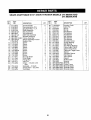
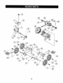
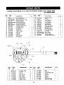
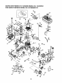
SEARS CRAFTSMAN
KEY
NO.
PART
NO.
1 611-0053
2 618-0043
3 618-0044
4 1618-0169
5
656-0012A
6 ,683-0024
7 i 684-0014A
8 684-0021
9 684-0031-0483
10 684-0042A
735-0243
11 710-0118
12 710-0599
13 710-0602
14 710-0604
15 710-0642
16 710-0654A
17 710-0788
18 710-0896
19 710-1233
20 711-0911
21 711-1042
22 712-0127
23 712-0711
24 713-0233
25
26
27
713-0413
713-0437
714-0474
9 H.P. SNOW THROWER
KEY I
DESCRIPTION
Axle Assembly
Dog Assembly--R.H.
Dog Assembly--L.H.
Shaft Assembly
Disc Assembly
Hub Assembly
Shift Rod Assembly
Bracket Assembly
Frame Assembly
Wheel Assembly Friction
Rubber Only
Screw
Screw
Screw
Screw
Screw
Screw
Screw
Screw
Screw
Actuator Shaft
Drive Shaft
Flange Nut
Jam Nut
Chain -- 1/2 pitch x 30
links
Sprocket -- 10 tooth
# 420 Chain -- 32 Links
Pin Cotter
NO.
QTY.
2
1
1
1
1
2
1
1
1
1
1
4
2
8
4
2
4
2
10
2
30
31
32
33
34
35
36
37
38
39
40
41
42
43
44
45
46
47
48
49
50
51
52
53
54
55
56
25
MODELS
PART
NO.
719-0295A
725-0157
732-0209
732-0264
736-0105
736-0160
738-0176
736-0242
736-0270
736-0287
738-0924
741-0339
741-0563
741-0597
746-0897
746-0898
746-09OO
748-0190
748-0234
750-0903
750-09O4
750-0997
756-0825
784-5590
784-5609-0483
784-5648-0483
784-5687-0483
784-5688-0483
784-5689-0483
247.885690 AND
247.88269CARB
DESCRIPTION
Housing Track
Cable Tie
Spring
Spring
Bell Washer
Fiat Washer
Flat Washer
Bell Washer
Bell Washer
Flat Washer
Shoulder Screw
Flange Bearing
Ball Bearing
Hex Flange Bearing
Cable-Auger Clutch
Cable-Drive Clutch
Cable with Trigger Lever
Spacer
Shoulder Spacer
Split Spacer
Split Spacer
Spacer
Roller-Cable
Bracket
Bracket
Cover-Frame
Bracket-Guide
Bracket-Guide
Bracket-Guide
QTY.
1
2
2
1
1
1
2
4
2
4
3
4
2
2
1
1
2
1
2
2
1
1
3
1
1
1
1
1
1
@
®
@
/
®
\
!
@J
®
®
26
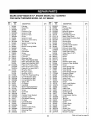
SEARS
KEY
NO.
1
2
3
4
5
6
7
10
11
12
13
14
15
16
17
18
19
2O
CRAFTSMAN
PART
NO.
631-0032
684-0009
684-0024
684-0038
710-0157
710-0459
710-0604
710-1231
712-0214
712-0267
712-0346
712-0429
720-0223
731-1292
731-1538A
736-0119
736-0242
736-0272
736-0406
737-0170
9 H.P. SNOW THROWER
I
i
QTY.
DESCRIPTION
Wheel Assembly Idler
Rod Track Pivot
Axle Assembly
Handle Assembly
Screw
Screw
Screw
Screw
Lock Nut
Hex Nut
Jam Nut
Hex Nut
Grip
Track
Wheel-Track Drive
Lock Washer
Bell Washer
Flat Washer
, Flat Washer
Lubricant
i
2
1
1
1
1
1
2
2
1
4
4
2
1
2
2
4
1
4
4
KEY
NO.
i
_
!
'
MODELS
247.885690 AND
247.88269CARB
PART
NO.
738-0140
21
748-0353A
22
750-0547
23
24
75O-O909
25
750-0995
26
784-5639-0483
784-5642
27
28 I 717-1211
29
717-1209
30
717-1210
31
741-0542
32
718-0188
33
618-0046
34
711-0912
35
713-0414
715-0120
36
736-0502
37
736-0336
38
716-0115
39
40
716-0114
DESCRIPTION
I Shoulder Screw
Lift-Shaft Drive
Spacer
Spacer
Spacer
Plate-Track Side
Plate-Track Lockout
Gear Ring
Gear 12-Tooth
Gear 18-Tooth
Pin Dowel
Carrier
Carrier Assembly
Shaft--Track Drive
Sprocket--13 Tooth
Spring Pin
Flat Washer
Flat Washer
Snap Ring .625" Shaft
Snap Ring .56" Shaft
LABELS
PART
NO.
I KEY
"i"
777-4865
777-4866
777-4867
777-4958
777-4959
777-4965
777-3396
777-8088B
DESCRIPTION
Traction Control R.H.
Traction Control LH.
Chute Tilt
Auger Control
Traction Drive
Transport
Danger Warning
Danger, Top of Chute
27
I
QTY.
4
1
2
2
2
2
1
2
6
2
6
2
2
1
1
1
6
2
2
1
\
\
\
!
!
\
28
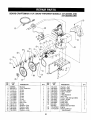
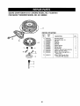
SEARS CRAFTSMAN
KEY
NO.
PART
NO.
9 H.P. SNOW THROWER
DESCRIPTION
1 05931
2 605-5193-0637
3 605-5192-0637
4 618-0121
5 684-0040A-0689
6 684-0064
7 684-0065-0637
8 705-5226
9 710-0167
10 710-0451
11 710-0604
12 710-0890
13 712-01!6
14 712-0267
15 712-0429
16 712-0798
17 712-3027
18 715-0114
KEYi
NO
PART
NO.
1
2
3
4
5
6
7
8
9
618-0123
618-0124
710-0642
711-0909
714-0161
715-0143
717-0526
717-0528
718-0186
QTY.
DESCRIPTION
IHousing--R.H.
IHousing--L.H.
Screw
Axle, Spiral
Key, Hi-Pro
Pin, Spiral
Worm, Shaft
Gear, Worm
Collar, Thrust
247.885690 AND
247.88269CARB
PART
NO.
DESCRIPTION
QTY.
1
1
9
1
1
6
16
1
2
1
1
4
1
2
1
2
1
19 731-1379
Adapter-Chute
20 732-0611
Spring
21 736-0119
Lock Washer
22 736-0167
Flat Washer
23 736-0169
Lock Washer
Flat Washer
24 736-0188
Bell Washer
25 1736-0242
26 738-0281
Shoulder Screw
27 741-0245
Flange Bearing
28 741-0309
Ball Bearing
29 741-0475
Plastic Bushing
30 741-0493A
Flange Bushing
Flat Idler
31 756-0178
Slide Shoe
32 784-5580-0689
33 784-5579A-0689 Shave Plate
34 784-5618
Housing-Bearing
35 784-5647
Bracket-Chute Crank
1
1
1
1
1
1
1
1
5
10
6
2
1
19
2
1
5
2
Housing-Bearing
Spiral Assembly--L.H.
Spiral Assembly--R.H.
Gear Assembly
Housing Assembly
Arm-Idler Assembly
Impeller Assembly
Reinforcement-Chute
Carriage Screw
Carriage Screw
Hex Screw
Shear Bolt
Hex Lock Nut
Hex Nut
Hex Nut
Hex Nut
Hex Lock Nut
Pin-Spring
i
' KEY
NO.
MODELS
QTY
KEY
NO
PART
NO.
1
1
5
1
1
1
1
1
1
10
11
12
13
!4
15
16
17
18
721-0325
721-0327
721-0328
736-0351
736-0369
736-0445
737-0168
741-0662
741-0663
29
I
I
I
I
DESCRIPTION
Plug
Seal, Oil
Loctite 5699, Ultra
Washer
Washer
Washer
Grease
Bearing Flange
Bearing Flange
QTY
2
4
1
1
1
1
SEARS CRAFTSMAN
REF.
NO.
PART
NO.
1
2
3
4
5
6
7
8
9
10
11
12
13
14
15
16
05896A
629-0071
710-0117
710-0157
710-0230
710-0342
710-0696
710-0888
710-0896
712-0181
731-1324
732-0710
736-0119
736-0242
736-0247
736-0329
DESCRIPTION
Bracket
Cord, Extension
Screw
Screw
Screw
Screw
Screw
Screw
Screw
Nut, Hex
Belt Cover
Spring
Washer--Flat
Washer--Bell
Washer--Flat
Washer--Lock
9 H.P. SNOW THROWER
REF.
NO.
QTY.
PART
NO.
17
18
19
20
21
22
23
24
25
26
27
28
1
1
1
1
1
1
1
1
2
I
I
I
1
1
1
1
736-0331
736-0505
748-0234
748-O36O
754-0346
754-O430
756-0313
756-O569
756-0967
756-0986
756-0987
390-985
390-987
143.979001
770-0373M
29
30
I
3O
MODELS
247.885690 AND
247.88269CARB
DESCRIPTION
Washer--Bell
Washer--Flat
Shoulder Spacer
Pulley, Adapter
V-Belt
V-Belt Matched
Idler, Flat
Pulley, Half (653 and 663)
Pulley--Auger
Pulley Half
Pulley Half
Starter (633)
Starter (653 and 663)
Engine
Owner's Manual
(Not Shown)
QTY.
1
1
1
1
1
2
1
4
2
1
1
1
1
1
1
SEARS CRAFTSMAN 9 H.P. ENGINE MODEL NO. 143.997001
FOR SNOW THROWER MODEL NO, 247.885690
CARBURETOR
KEY
NO.
I
[
i
0
PART
NO.
t
632370A
1 631776A
2 631970
6 i631778
7 650506
10 632112
14 632174
15 630735
16 632164
!7
650417
18
20
21
22
23
25
630766
632281
630766
630739
630740
631951
27
28
29
30
631024
632019
631028
631021
31
32
33
40
631022
27136A
27554
632239
41
630740
42
630739
43
630738
44
47
48
27110
630748
631027
60
632347
31
DESCRIPTION
Carburetor (Incl. 184 of
Engine Parts List)
Throttle Shaft & Lever Ass'y.
Throttle Return Spring
Throttle Shutter
Shutter Screw
Choke Shaft & Lever Ass'y.
Choke Shutter
Choke Positioning Spring
Fuel Fitting
Throttle Crack Screw/Idle
Speed Screw
Tension Spring
Idle Mixture Screw
Tension Spring
Idle Mixture Screw Washer
Idle Mixture Screw "O" Ring
Float Bowl Ass'y. (Incl. 32 &
33)
Float Shaft
Float
Float Bowl "O" Ring
Inlet Needle, Seat & Clip
(Incl. 31)
Spring Clip
Bowl Drain Ass'y.
Drain Plunger Gasket
Main Adj. Scr. Ass'y.
(Incl. 41 thru 44)
High Speed Mixture Screw
"O" Ring
High Speed Mixture Screw
Washer
High Speed Mixture Screw
Tension Spring
Bowl Nut Washer
Welch Plug, Idle Mixture Well
Welch Plug, Atmospheric
Vent
Repair Kit (Incl. Items Marked
PK in Notes)
Incl. Part Nos. 27110 (1),
630740 (1), 630748 (1),
631021 (1), 631022 (1),
631024 (1), 631027 (1),
631028 (1), 632239 (1),
632281 (1)
QTY.
1
1
1
1
2
1
1
1
1
1
1
1
1
1
1
1
1
1
1
1
I
1
1
SEARS CRAFTSMAN 9 H.P. ENGINE MODEL NO. 143.997001
FOR SNOW THROWER MODEL NO, 247.8856903131
114
116
,115
132
117
133
\
I
11
20
i
118
10
\
45
36
119
112
39 /
1
26
17
70/i
72/_--
48
49
_70
73
72
_\73
il 1
41
123
!
!
96
I o7
J
77
98
15
81
5
122
i_
128
130
138 137
93
_136
94
125
108 5
/
131
126
52
133
109
32
SEARS CRAFTSMAN
9 H.P. ENGINE MODEL NO. 143.997001
FOR SNOW THROWER MODEL NO. 247.885690
KEY
NO.
PART
NO.
1 35385
2 27652
3 650820
4 30969
5 30699C
6 30700
7 650494
8 33454
9 29916
10 651028
11 34663
12 35319
13 36460
14 650561
15 30322
16 35980A
17 29826
18 29918
19 29216
20 29642
21 34552
34553
i34554
22 134329A
34330A
34331A
23 34332
34333
34334
24 i27888
25 35373A
26 650908
27 i650882
28 i34034
29 i35374
30 36655
31 33273A
32 i 34126
33 i650760
34 28545
35 650128
36 35262A
37 i35445A
38 i35377
39 i 35319
40 i 28926
41 31845
42 30590A
43 35378
44 i 30588A
45 29193
46 650833
I KEY
DESCRIPTION
Cylinder
Dowel Pin
Screw
Extension Cap
Governor Rod
Governor Yoke
Screw
Governor Lever
Governor Lever Clamp
Torx Screw
Speed Control Spring
Oil Seal
Blower Housing Baffle
Screw
Lock Nut
Crankshaft
Screw
Lock Washer
Lock Nut
Retaining Ring
Piston, Pin& Ring Set (Std.)
Piston, Pin & Ring Set (.010")
Piston, Pin & Ring Set (.020")
Piston & Pin Assy. (Std.)
Piston & Pin Assy.(.010")
Piston & Pin Assy.(.020")
Ring Set (Std.)
Ring Set (.010")
Ring Set (.020")
Piston Pin Retaining Ring
Connecting Rod Assy.
Connecting Rod Bolt
Connecting Rod Bolt
Valve Lifter
Oil Dipper
Camshaft
Blower Housing Extension
Grommet Mount. Bracket
Screw
Grommet
Screw
Cylinder Cover Gasket
Cylinder Cover
Crankshaft Bushing
Oil Seal
Camshaft Seal
Governor Shaft
Washer
Governor Gear Assy.
Governor Spool
Retaining Ring
Screw
QTY.
1
2
2
1
1
1
1
1
1
1
1
1
1
2
1
1
1
1
1
1
1
1
1
1
1
1
1
1
!
2
1
1
1
2
1
1
1
1
1
1
1
1
1
1
1
1
1
1
1
1
1
7
I NO.
=, 47
48
49
5O
51
52
53
54
55
56
57
58
59
60
61
62
63
64
65
66
67
68
69
70
71
72
73
74
75
76
77
78
79
8O
81
82
83
84
85
86
87
88
89
9O
91
92
93
94
95
96
33
PART
NO.
650832
32589
611093
650880
650881
35135
610118
650872
651007
35253
35305
36448
36449
27878A
27880A
34035
34036
650691
6021A
650727
650713
33636
33369
650836
27882
35862
27881
32581
27896A
28423
28424
28425
35350
650128
29752
34587A
33263
33877
34667
36652
34677
31342
650549
610973
33878
650821
35440
35438
28820
650378
27915A
35447A
DESCRIPTION
!
Screw
Flywheel Key
Flywheel
Belleville Washer
Flywheel Nut
Solid State Ignition
Spark Plug Cover
Solid State Mounting Stud
Screw, Torx
Ground Wire
Ground Wire
Cylinder Head Gasket
Cylinder Head
Exhaust Valve (Std.)
Exhaust Valve (!/32")
Intake Valve (Std.)
Intake Valve (1/32")
Washer
Screw
Screw
Screw
Resistor Spark Plug
Governor Gear Bracket
Screw
Valve Spring Cap
Valve Spring Cap
Valve Spring
Valve Spring Keeper
Breather Gasket
Breather Body
Breather Element
Valve Cover
Breather Tube
Screw
Nut & Lock Washer
Choke Bracket
Gasket
Intake Pipe
Governor Link
Choke Spring
Control Bracket
Compression Spring
Screw
Terminal
Throttle Link
Screw
Control Knob
Choke Rod
Screw
Screw, Torx
Intake Pipe Gasket
Blower Housing
QTY.
1
1
1
1
2
1
1
2
2
1
1
Table continued on page 34.
SEARS CRAFTSMAN 9 H,P. ENGINE MODEL NO. 143.997001
FOR SNOW THROWER MODEL NO. 247,885690
Table continued from page 33.
KEY
NO.
PART
NO,
97 650788
98 29747B
99 33272B
100 35056
101 31588
102 651002
103 33013
104 650760
105 29752
106 35985B
107 30705
108 26460
109 650665
110 34156A
111 35355
112 35554
113 35499
114 35540
115 36205
116 35189
117 650873
118 611111
119 611118
120 129443
121 35392
122 35593
123 _610973
124 650257
125 35057A
126 650765
DESCRIPTION
Screw
Screw,
Torx
Cylinder Head Cover
Muffler
Locking Plate
Screw
Starter Bubble Cover
Screw
Nut & Lock Washer
Starter Cup
Fuel Line
Fuel Line Clamp
Screw
Fuel Tank
Fuel Cap
Oil Fill Tube
O Ring
Fill Tube Clip
Dipstick
Spacer
Screw
Alternator Coil
Terminal
Wire Clip
Starter Plug
Ignition Key
Terminal
Screw
Carburetor Cover
Screw
KEY
NO.
QTY.
2
2
1
1
1
2
1
1
4
1
1
4
2
1
1
1
1
1
1
1
1
1
1
1
1
2
1
2
1
1
127
128
129
130
131
132
133
134
135
136
137
138
139
140
141
142
143
144
145
146
147
148
149
150
151
152
153
154
155
156
34
PART
NO.
28942
34154
34155
650561
570682
32180C
590574
33377
650765
28942
34154
34155
650561
570682
32180C
590574
33377
34414
36261
34418
36501
35063
36695
632371A
590707
33328D
36454
730225
36705
650542
DESCRIPTION
Screw
Fuel Tank Bracket
Fuel Tank Bracket
Screw
Primer Assy.
Primer Line
Starter Handle
Carburetor Cover
Screw
Screw
Fuel Tank Bracket
Fuel Tank Bracket
Screw
Primer Assy.
Primer Line
Starter Handle
Carburetor Cover Bracket
Warning Decal
Instruction Decal
Warning Decal
Primer Decal
Instruction Decal
Starter Decal
Carburetor
Rewind Starter
Electric Starter Motor
Gasket Set
Engine Oil
Engine Mounting Base
Screw
QTY.
2
1
1
1
1
1
1
1
1
2
1
1
1
1
1
1
1
1
1
1
1
1
1
1
1
1
1
1
1
4
SEARS CRAFTSMAN
9 H.P. ENGINE MODEL NO. 143.997001
FOR SNOW THROWER MODEL NO. 247.885690
--11
RECOIL
KEY
NO.
/
12
13
O
4
35
STARTER
PART
NO.
0
1
2
3
4
5
6
7
8
11
12
590733
590599A
590600
590696
590601
590697
590698
590699
590709
590734
590535
13
590574
DESCRIPTION
Rewind Starter
Spring Pin (Incl. 4)
Washer
Retainer
Washer
Brake Spring
Starter Dog
Dog Spring
Pulley & Rewind Spring Ass'y.
Starter Housing Ass'y.
Starter Rope (Length 98" x
9/64" Dia.)
Mitten Grip Handle (Not
Included With Starter)
QTY.
1
1
1
1
1
1
2
2
1
1
1
1
Fortherepairor replacementpartsyouneed
delivereddirectlyto yourhome
Call 7 am - 7 pm, 7 days a week
1-800-366-PART
(1-800-366-7278)
Forin-homemajorbrandrepairservice
Call24 hours a day,7 daysa week
1.800.4.REPAI
R
(1-800-473-7247)
Forthelocationofa
Call24
hoursRepairCenterinyourarea
a day,7 daysa week
_--==
Sears
Partsand
[m
1-800-488-1
222
Forinformationonpurchasing
a Sears
MaintenanceAgreementorto inquire
aboutanexistingAgreement
call 9 am - 5 pro, Monday-Saturday
1-800-827-6655
SF_ARS
America's
Repair Specialists
SEARS
nmmmmm
mmmmmm
_8
Manual Del Propietario
+CRAFTSMAN°
EXPULSOR DE NIEVE
9 CABALLOS DE FUERZA
PROPULSION DE ORUGA DE DOS ETAPAS DE 26"
No. De Modelo
247.885690
247.88269CARB
Precauci6n:
Lea y siga todas
las reglas e instrucciones
de
seguridad antes de operar este
equipo
Sears, Roebuck
And Co., Hoffman
Estates,
IL 60179 USA
770-0373M
8/96
(R960823)
Garantia .....................................................................
Operaci6n segura .......................................................
Paquete de ferreteria ..................................................
Ensamblado ................................................................
Operaci6n ...................................................................
Mantenimiento ..........................................................
GARANTIA
1
2
4
5
9
14
Responsabilidades del cliente ..................................
Ajuste .......................................................................
Almacenamiento fuera de temporada ......................
Localizaci6n de fallas ...............................................
Piezas de repuesto ..................................................
LIMITADA DE UN ANO PARA EL EXPULSOR
15
18
19
20
21
DE NIEVE CRAFTSMAN
Per un arc desde la fecha de compra cuando este expulsor de nieve Craftsman sea mantenido, lubdcado y puesto a punto de acuerdo
con las instrucciones de operaci6n y mantenimiento en el manual del propietario, Sears reparar_filibre de costo cualquier defecto de
material o de mano de obra.
Esta garantia se aplica por 30 dfas solamente a partir de la fecha de compra, si el expulsor de nieve se usa para fines comerciales o de
alquiler.
Esta garantia no cubre:
Articulos desechables que se desgastan durante el use normal, tales cemo zapatas deslizantes, placa raspadora y buj[as.
Reparaciones necesarias a causa de abuse o negligencia per parte del operador, incluyendo cigQedales doblados y la falla en
mantener el equipo de acuerdo con las instrucciones contenidas en el manual del propietario.
EL SERVICIO DE GARANTIA ESTA DISPONIBLE SI SE DEVUELVE EL EXPULSOR DE NIEVE CRAFTSMAN AL CENTRO/DEPARTAMENTO DE SERVICIO DE SEARS MAS CERCANO EN LOS ESTADOS UNIDOS.
Esta garantia se aplica solamente mientras este producto est_ en uso en los Estados Unidos.
Esta garantfa le otorga derechos legales especificos y usted puede tambi6n tener otros derechos que varian de Estado a Estado.
SEARS, ROEBUCK AND CO. DEPT. D817WA, HOFFMAN STATES, IL 60179
ESPECIFICACIONES
Caballos
de fuerza:
DEL PRODUCTO
9 h.p.
Numero
De Modelo:
247.885690/247.88269CARB
Desplazamiento:
19.43 pies.cub.
Numere De Serie:
Capacidad
4 cuartos
Fecha De Compra:
Bujfa
J-8C o equivalente
Motor
MQDELO
143.979001
Los numeros de modelo y de serie se encuentran en el
rotulo pegado al armazon del expulsor de nieve.
(247.885690)
MODELO 143.979007
Usted deberia registrar el numero de serie y la fecha de
compra y guardarlos en un lugar seguro para referencia
futura.
de combustible:
(247.88269CARB)
ESTE SIMBOLO INDICA INSTRUCCIONES IMPORTANTES DE SEGURIDAD LAS CUALES, SI NO SE
SIGUEN, PUEDEN PONER EN PELIGRO LA SEGURIDAD PERSONALY/O LA PROPIEDAD SUYAY
AJENA. ANTES DE INTENTAR OPERAR SU EXPULSOR DE NIEVE LEAY SIGATODAS LAS INSTRUCCLONES EN ESTE MANUAL. LA FALTA DE CUMPLIMIENTO CON ESTAS INSTRUCCIONES PUEDE
RESULTAR EN LESIONES PERSONALES.
ADVERTENCIA: Esta unidad esta equipada con un motor de combusti6n interna y no debe usarse en o cerca de tierras no mejoradas cubiertas de bosques, matorrales, yio hierbas, a menos que el sistema de escape est6 equipado
con un supresor de chispas que cumpla con las leyes del estado o federales aplicables (de existir), si se usa un supresor de ch spas debe ser mantenido en buenas condiciones de trabajo por el operador. En el Estado de California Io
indicado arriba es requerido pot ley (Secci6n 4442 del CSdigo de Recursos Pt_b cos de Ca fornia). Otros Estados
pueden tener leyes similares. Las teyes federales se aplican en las tierras federales. Esta disponible un supresor de
chispas para el silenciador en su Centre de Servicio Autorizado Sears mAs cercano (Vea la secciSn de PIEZAS DE
REPUESTO de este manual).
ENTRENAMIENTO
•
•
•
•
•
Lea cuidadosamente en su totalidad esta gu_a del propietario antes de tratar de ensamblar u operar esta
maquina. Familiarfcese completamente con los controles y el uso correcto de esta m_.quina antes de operaria. Mantenga este manual en un lugar seguro para
referencia futura y regular y para ordenar piezas de repuesto.
Nunca permita que nifios menores de 14 afios operen un
expulsor de nieve. Los niflos de 14 aflos y mayores deben operar el expulsor de nieve baje una supervisi6n
paterna estricta. Debe permitirse el uso de su expulsor
de nieve alas personas bien familiarizadas con estas
reglas de operaci6n segura solamente.
Nadie que este intoxicado o que est6 tomando medicinas que debiliten los sentidos o las reacciones debe operar esta unidad.
Mantenga el _.rea de operaci6n despejada de todas las
personas, especialmente nifios pequefios y animales
dom6stices.
Sea precavido pare evitar resbalar o caer, especialmente al operar en marcha de retroceso.
•
Antes de comenzar e despejar la nieve, permita que el
motor y la m#.quina se ajusten ala temperatura exterior.
Durante la operaci6n o mientras efectQa un ajuste o reparaci6n, use siempre lentes de segurided o protectores
de ojos, para proteger los ojos contra objetos extrafios
que puedan ser despedidos por la mAquina en cualquier
direcciSn.
•
OPERACION
•
•
•
•
•
PREPARACION
•
Inspeccione completamente el Area donde se usara el
equipo y retire todos los felpudos, trineos, tables, cables y otros objetos extrafios.
e Desenganche todos los embragues y cambie a neutro
antes de arrancar el motor.
• No opere el equipo sin usar ropas externas de invierno
adecuadas. No use joyas, bufandas largas ni otras
ropas holgadas que podrfan enredarse en las piezas
m6viles. Use calzado que mejore la firmeza de su paso
sobre superficies resbaladizas.
® Apague todos los cigarrillos y otras fuentes de encendido, antes de trabajar con gasolina. Inspeccione el combustible antes de arrancar el motor. La gasolina es un
combustible extremadamente inflamab[e. No Ilene el
tanque de gasolina bajo techo, mientras este funcionando el motor, o hasta que se haya permitide que el motor
se enfrfe durante dos minutos por lo menos. Antes de
arrancar el motor, vuelva a colocar seguramente la tapa
de gasoline y limpie toda ta gasoline derramada, ya que
de Io contrario puede causarse un incendio o una explosi6n.
t Para todas tas unidades con motores de propulsi6n el6ctrica o con motores de arranque electrico use un enchufe de tres cables conectado a tierra.
• Ajuste la altura del armaz6n colector para despejar una
superficie de pedregullo o roca triturada.
o Nunca trate de efectuar ajustes mientras el motor esta
funcionando (excepto donde se recomiende especfficamente por el fabricante).
•
•
•
•
•
•
•
No coloque las manos ni los pies cerca o debajo de piezas giratorias. Mant6ngase alejado en todo momento de
la abertura de descarga y de la h61ice.
Sea muy precavido al operar o cruzar sobre entradas de
pedregullo, senderos o caminos. Permanezca alerta
per riesgos ocultos o tr__fico.
No transporte pasajeros.
Despu6s de golpear un objeto, apague el motor, extraiga
el cable de la bujfa, e inspeccione completamente el expulsor de nieve por averfas. Antes de velvet a arrancar y
operar el expulsor de nieve, repare las averfas.
Si el expulsor de nieve comienza a vibrar anormalmente,
apague el motor e inspeccione inmediatamente por la
causa. La vibraci6n es generalmente una advertencia
de problemas.
Apague el motor siempre que deje la posiciSn operativa,
antes de destapar el armaz6n del colec¢or/proputsor o la
gufa de descarga, y efectuar reparaciones, ajustes, o inspecciones. Nunca coloque su mano en las aberturas de
descarga o de coiecta. Use un palo o un mango de madera de escobiit6n para destapar la abertura de descarga.
Tome todas las precauciones posibles al dejar la unidad
desatendida. Desenganche el colector/propulsor, cambie e neutro, arranque el motor, y extraiga la Ilave.
AI limpiar, reparar o inspeccionar, asegL_rese que se
hayan detenido el colector/propulsor y todas las piezas
moviles. Desconecte el cable de la bujfa y mantengalo
alejado de la bujfa pare prevenir un arranque accidental.
No haga funcionar el motor bajo techo, excepto cuando
arranque el motor y cuando transporte el expulsor de
nieve dentro o fuera del edificio. Abra las puertas. Los
humos de escape son peligrosos.
No despeje nieve a traves de la superficie de pendientes. AI cambiar de direcci6n en las pendientes sea
muy precavido. No intente despejar pendientes muy
pronunciadas.
Nunca opere el expulsor de nieve sin que las guardas,
places, u otros mecanismos protectores de seguridad,
esten en su lugar.
Nunca opere el expulsor de nieve cerca de cerramientos
de vidrio, autom6viles, marcos de las ventanas, cafdas,
etc. sin el ajuste correcto del &ngulo de descarga del expulsor de nieve. Mantenga alejados a los nifios y a los
animales dom_sticos.
•
•
•
•
•
•
No intente sobrecargar la capacidad de la maquina intentando despejar la nieve a una velocidad demasiado
elevada. Nunca opere la mAquina a altas velocidades de
transporte sobre superficies resbalosas. Mire hacia
atras y sea precavido al retroceder.
Nunca difija la descarga hacia los observadores ni permita que nadie se pare delante de la unidad
Cuando transporte o no est_ en uso desconecte la potencia al colector/propulsor.
Use s61o aditamentos y accesorios aprobados por el fabricante del expulsor de nieve (tales come pesos de ]a
rueda, contrapesos, cables, etc.)
Nunca opere el expulsor de nieve sin buena visibilidad o
luz. Siempre est6 seguro de su equilibrio y sujete bfen
los mangos. Camine, nunca corra.
El silenciador y el motor se calientan y pueden causar
una quemadura. No los toque.
MANTENIMIENTO
•
•
•
•
•
Si el expulsor de nieve va a ser almacenado durante un
periodo prolongado de tiempo, refi_rase siempre alas
instrucciones en la gufa del propietario para detalles importantes.
Haga funcionar la m__quina por unos pocos minutos
despues de expeler la nieve, para prevenir la congelaci6n de colectodpropulsor.
Inspeccione peri6dicamente los controles del embrague
para verificar que se enganchen y desenganchen adecuadamente y reajuste si fuera necesario. Para las instrucciones de ajuste refi6rase a la guia del propietario.
Y ALMACENAMIENTO
Inspeccione los pernos de corte, pernos de montaje del
motor, etc., a intervalos frecuentes para un ajuste correcto para asegurarse que el equipo est6 en una condici6n segura de trabajo.
Nunca almacene la m&quina con combustible en el
tanque de combustible dentro de un edificio donde est_n
presentes las fuentes de encendido, tales como calentadores de agua y ambiente, secadoras de ropa, y similares. Permita que el motor se enffie antes de
almacenar en cualquier recinto.
BUSQUE ESTE SIMBOLO PARA INDICARPRECAUCIONES IMPORTANTES DE SEGURIDAD.
iiiSIGNIFICA
ATENCION!!Z
iiiESTE ALERTA!!! ESTA EN JUEGO SU
SEGURIDAD.
Estos sfmbolos figuran en su unidad. Aprenda y entienda su significado, y sigalos para asegurar la operaciSn
segura de su expulsor de nieve Sears.
Llave de encendido
4_
Fast
I'_
Regulador en OFF
!-_
Regulador
H
Regulador en FULL
=_
_
Inserte
para funcionar
Lento
_
Extraigaparaapagar
Estos accesorios estaban disponibtes cuando se compr6 el expulsor de nieve. Estan tambien disponibles en la
mayoria de las tiendas minoristas de Sears y centros de catalogos y servicio. Cuando usted provea el nemero de
rnodelo de su expulsor de nieve, la mayorla de las tiendas de Sears pueden ordenar piezas de repuesto para usted.
MOTOR
Aceite de dos
tiempos
Recipiente de
gasolina
MANTENIMIENTO
Bujia
DEL EXPULSOR DE NIEVE
Barra raspadora
Correa
Despliegue la ferreter[a de acuerdo con la ilustraci6n para fines de identificaci6n. Las piezas estan ilustradas a la
mitad de su tamaSo aproximadamente. Los nQmeros de pieza se muestran entre par6ntesis.
(El paquete de ferreteria puede contener artfculos adicionales que no se usan en su unidad)
A.__ FIJACION
DEL CONJUNTO
DEL MANGO
_
I /_
,.0.,,,0,
ml
_
__
@_
_,_..._.
_
@@
Arandelas de
seguridad
D.I. 5/16"
Tornillos de cabeza
hexagonal
[@1 T
(710-3051 )
Vea la nota de abajo.
T
@@_
_i=_
_..
_
('#'_t'_-'_(,r_-_(f_-_
Aletas del mango
(784-5599)
(736-0119)
Pernos de,.carro
e I FIJACIONDEL CONJUNTODELA CANALETA
Vea la not_bajo.
5/16-18xl-3/4"
de largo
Pernos hexagonales
(710-0118)
r
Tornillosdacabeza
hexagonal
!1/4-20x3/4" de largo
I
(710-305!)
Contratuercas
_>_ hexagonales
Rosca de 1/4-20
@
Y_
__
5,16-1( qo]4 5od;,larg
I
Contratuercas
acopadasD.I.5/16"_
Arandelas____
(736-0242) _
U
}
[ _
Tuercas hexagonales
Rosca de 5/16_
(712-0267) "----'_f
@
Guardas de la
brida de la
canaleta
(731-0851 A)
_lRoscadel/4-20
hexagonalas(712.3027)
@
C_.€__.J
FIJAClON
DE LA MANIVELA
DE LA CANALETA
Arandelas planas
3/8" D.I. x 5t8" DoE.
Perno hexagonal
de largo _]
(710-0442)
5116-18 x 1-1/2"_
o_o_J
FIJACION DE LA VARA DE CAMBIO Y DE
LOS CABLES DEL EMBRAGUE
Arandela de segu- _1
ridad 5/16" D.I.
Broche de
cabello
(714-0104)
F.__ TUERCAS
Casquillo
(711-0677)
(712-0267) _
DE CORTE
@
(_.
_)_
cabello ---_1_11_I_
(714-0104)
3!8"
D.I. x 5/8"
D.E.
Arandelas
planas
(736-0264)
DE LA HELICE
[_as h#lices estan fijados al eje en espiral con dos pernos hexagonales y las
contratuercas hexagonales de inserci6n. Si usted golpea un objeto extra5o o
se atasca con hielo, el expulsor de nieve estd diseRado de manera que los pernos hexagonales se cortaran. Para su conveniencia se proveen dos pernos y
tuercas hexagonales. Almacene en un lugar segu ro hasta que se necesilen.
nales
5/16-18 x 1-1/2"
I !"_'--" de largo
__
Broches de
(736-0119)-.._
Tuerea hexagonal
5/16-18 de rosca
i"J_3 Pernos hexago__
(710-0890A)
Contratuercas
hexagonales
_
Arandela
resorte
5/16"deiD.I.
(736-0271)
Nota: Se usan seis de los tornillos de cabeza hexagonal y
seis de las contratuercas hexagonales para fijar las guardas
de la brida de la canaleta al armaz6n del ventilador. Los dos
tornillos restantes se necesitan SOLAMENTE si el expulsor
de nieve tiene los mangos corvos.
IMPORTANTE: Esta unidad ha sido despachada sin
gasolina ni aceite. Despuds del ensamblado, vea la
secci6n de operaciones de este manual para las
recomendaciones sobre combustible y aceite de
motor apropiados.
NOTA: Para determinar los lados derecho e
izquierdo de su expulsor de nieve, p_rese detras
en la posici6n operativa normal.
Control de la propulsi6n de tracci_n
Panel del mango
\
Mangos
PREPARACION
DE SU EXPULSOR
ADVERTENCIA:
DE NIEVE
Antes de ensamblar el
,_
expulsor
debujia
nieve,
asegdrese
que el y qu_
cable
de la
estd
desconectado
est_ alejado de la buj_a.
FIJACION DEL CONJUNTO DEL MANGO
• Estire los cables de control y coloque sobre el piso.
• Coloque el mango derecho en posici6n con el
lado piano contra el expulsor de nieve. Usted
puede identificar el mango derecho por la etiqueta
de control del propulsor de tracci6n sobre el mismo, y el mango izquierdo por la etiqueta de control
del embrague de la h61ice sobre el mismo.
• Asegure los orificios del fondo del mango al expulsor de nieve usando pernos hexagonales de 5/8"
de largo y arandelas de seguridad. Vea la figura 2.
No ajuste en este momento.
Canaleta
"
__--
desegu-
_/'..._._'%.\_ .ridad....
Perno_,'_.
/?/
/\
Manivela
dela
canaleta
Vara de
cambio
//
_b
largo
FIGURA 2
FIGURA 1
EXTRACCION DE LA UNIDAD DE LA CAJA
• Corte las esquinas de la caja.
• Extraiga todas las inserciones de empaque.
• Ruede el expulsor de nieve fuera de la caja.
• Antes de descartar la caja, asegL_rese que se
hayan extraido todas las piezas y la literatura.
PIEZAS SUELTAS EN LA CAJA
(1) Paneldel man goy conjuntode la canateta(fijado por cable)
(1) Mangodelladoderecho
(1) Mangodel lack)izquierdo
(1) Conjuntodela manivelade lacanaleta
(1)Varadecambio
NOTA: Extraiga la canaleta de la caja y col6quela
sobre el tope del motor. No desempaque la canaleta
hasta que haya instalado el panel del mango, los
cables del embrague y la cubierta de la correa.
HERRAMIENTAS
• Coloque las aletas del mango sobre los orificios
superiores en el mango, de manera que la curva
en la aleta del mango corresponda con la eurva en
los mangos.
• Asegure el expulsor de nieve usando pemos hexagonales de 1-3/4" de largo y arandelas de seguridad. No ajuste en este momento.
• Fije el mango izquierdo de la misma manera. No
ajuste en este momento.
• Coloque el panel del mango en posici6n entre los
mangos.
Por favor coloque en posicion el panel del mango entre
los mangos, de manera que los extremos del mango
pasen a traves de las ranuras del panel del mango.
REQUERIDAS
Llave de 1/2"
Llave de 7/1 6" o Ilaves ajustables
Par de tenazas
Juego de destomilladores
PAQUETE
DE FERRETERIA
Despliegue laferreterfa de acuerdo con las ilustraciones
y nL_meros de pieza listados en la pagina 4. Identifiquelos con las tareas especfficas en la secci6n de Ensamblade.
FIGURA 3
•
Alinee los orificios en el mango con los orificios a
los dos lados del panel del mango.
• Asegure la parte posterior del panel del mango con
dos pemos hexagonales y las tuercas de la brida.
Vea la figure 3.
• Asegure con los cuatro pemos del carro, arandelas acopadas (lado acopado contra el panel del
mango) y tuercas hexagonales segen se muestra
en la figura 3. Alinee el contorno de! cabezal del
perno transportador con el mango.
• Ajuste toda la ferreterfa fioja en et conjunto del
mango -- primero los pernos hexagonales al rondo del mango, a continuaci6n los pernos transportadores y finalmente los pernos hexagonales en
la parte posterior del panel del mango.
FIJACION DEL CONJUNTO DE LA CANALETA
NOTA: Aseg_rese que los cables de la canaleta est_n
enderezados mientras esta ensamblando la canaleta.
• Coloque el conjunto de la canaleta sobre la abertura
de la canaleta, con la abertura en el conjunto de la
canaleta enfrentando la parte delantera de la unidad.
• Coloque las guardas de la brida de la canaleta debajo del reborde del conjunto de la canaleta.
Conjunto de
la canaleta
Contratuercas
hexagonales
Contratuerca
,
\
FIGURA
,/hexagonal
Guarda de la
_. brida de la
4
canaleta
•
Inserte el perno hexagonal a trav_s de la guarda
de la brida de la canaleta y del conjunto de la
canaleta segdn se muestra en la figura 4. Asegure
con la contratuerca hexagonal.
e Despues de ensamblar todas las tres guardas de
la brida de la canaleta, ajestelas y afloje 1/4 de
vuelta para permitir un movimiento m_.sfAcil.
ATTACHING
CANALETA
•
DE LA MANIVELA
DE LA
Inserte el perno hexagonal a tray,s del soporte superior de la manivela de la canaleta. Vea la figura 5.
• Coloque el pemo hexagonal dentro del orificio provisto en el mango izquierdo. Asegure con la contratuerca y la tuerca hexagonal.
Pernos y contratuercas
hexagonales del carro
Soporte
inferior de
manivela de
la canaleta
FIGURA 6
• No ajuste hasta fijar el otro extremo de la manivela
de la canaleta.
• Afloje los pernos del carro y las contratuercas hexagonales que aseguran el soporte inferior de la
manivela de la canaleta a la prolongaci6n del lado izquierdo del conjunto de la canaleta. Vea la figura 6.
• Coloque una arandela plana sobre el extremo de
la manivela de la canaleta y a continuacion inserte
el extreme de la manivela dentro det orificio en el
manguito plAstico en el soporte de la manivela de
ia canaleta. Vea la figura 7.
• Coloque la otra arandela plana sobre el extremo de
la manivela de la canaleta e inserte la chaveta en el
extremo de la manivela. Asegure doblando los extremos de la chaveta en direcciones opuestas.
• Ajuste el soporte de la canaleta de manera que la
espiral de la maniveta de la canaleta enganche
completamente los dientes del conjunto de la
canaleta. Ajuste seguramente las tuercas en el soporte inferior de la manivela de la canaleta.
• Ajuste el perno hexagonal y la tuerca en el soporte
superior de la manivela de la canaleta en el mango.
Contratuerca
Tuerca hexm
,_.,2
Perno
FIJACION
_
Arandelas
Manivela de la
planas
canaleta
hexagonal
so
!
de la manivela
de la canaleta
Soporte inferior de la
manivela de la
FIGURA 5
canaleta
FIGURA
7
Manguito pl_stico
•
Deslice los cables que se extienden desde el panel
del mango a la canaleta dentro de la gufa de cable
ubicada en el tope del motor. Vea la figura 8.
Guia del
cable
FIGURA 8
IMPORTANTE: Fije la vara de cambios y los cables
del embrague como sigue. A continuaci6n inspeccione
los ajustes segt_n las instrucciones, y efectQe todos
los ajustes finales necesarios antes de hacer funcionat su expulsor de nieve. El no seguir las instrucciones puede causar averias al expulsor de nieve.
FIJACION DE LA VARA DE CAMBIOS
• Coloque la palanca de cambios en la posici6n de
sexta (6) velocidad.
• Coloque el extremo doblado de la vara de cambio
dentro del orificio en el conjunto del brazo de cambios. Vea la figura 9. Asegure con la arandela del
resorte, arandela plana y broche de cabello.
• Comience a enroscar el casquillo dentro del otro
extremo de la vara de cambios. Presione hacia
abajo sobre la vara de cambios (y sobre el conjunto del brazo de cambios) tanto como pueda.
• Enrosque el casquillo sobre la vara de cambios
hasta que el casquillo se alinee con el orificio superior en la palanca de cambios (debajo del panel
del mango).
Embraguedel
pro!
tracci6n
Palanca de
cambios
Control de la
distancia dela
canaleta
j
• Una vez que el casquillo se desliza dentro del
orificio, retroceda una vuelta completa en sentido
contrario alas agujas del reloj al casquillo con la
varilla y mueva la palanca de cambios hacia la
quinta posici6n.
NOTA: Puede ser necesario tirar de la palanca de cambios fuera de la posici6n de sexta velocidad y moverla
hacia la posici6n de quinta velocidad hasta que el
casquillo se deslice dentro del orificio sin esfuerzo.
• Inserte el casquillo dentro del orificio superior en la
palanca de cambios desde el lado izquierdo cuando el ajuste es correcto. Asegure con la arandela
plana y el broche del cabello.
• Aseg_rese de inspeccionar per un ajuste correcto
de la vara de cambios segLin las instrucciones de
la secci6n de Ajuste Final, antes de hacer funcionar el expulsor de nieve.
FIJACION DE LOS CABLES DEL EMBRAGUE
• Levante la cubierta pl_stica negra de la correa fuera del frente hacia el armazdn del motor. Extraiga
los dos tornillos autoroscantes del armaz6n del
motor (despachados flojos en posici6n) que se usar#.n para instalar la cubierta.
• Inspeccione y asegL_rese que el cable esta en la
hendidura de todos los tres rodillos gu[a del cable.
• Enrosque las contratuercas hexagonales (en el
paquete de ferreter[a) toda la distancia hasta la
porci6n roscada de los extremos en Z de los cables del embrague.
• AsegOrese que cada cable este en la ranura de las
gu[as del rodillo del cable. Coloque la empuSadura
del embrague en la posici6n elevada (up).
• Enrosque el cable dentro de la porci6n roscada del
extremo en Z y hasta que no haya exceso en el
cable, pero que el cable NO est6 tirante. Vea la
figura 10.
ADVERTENClA: Pueden anularse las caracterfsticas
de seguridad del expulsor de nieve, si el cable esta tan
tirante que hay tensi6n en el cable estando suelta la
empuSadura del embrague.
• Ajuste la tuerca hexagonal contra la porci6n del
fondo del cable para asegurarlo en posici6n,
cuando se alcance el ajuste correcto.
Cubierta
Orificio
superior en la
palanca
carnbios
Correa
randela
plana
cabello
Arandela
del resorte
cabello
Arandela
plana
cambios
Con junto del
brazo de
cambios
FIGURA 9
FIGURA 10
FIJACION DE LOS GATILLOS PARA G|RO
IZQUIERDO Y DERECHO
• Extraiga el tornillo del tope del gatillo de giro derecho. Tenga cuidado de no perder la tuerca soldada.
• Extraiga el gatillo del cable tirando del cable hacia
afuera y hacia abajo. Deslice la boliUa del cable
fuera de la ranura.
• Alimente el cable del gatillo hacia arriba a traves
del lado exterior de la ranura en el panel plastico
del mango. No alimente el cable a traves det
mismo lado de la ranura que el adaptador en Z.
• Deslice y gire la bolilla del cable dentro de la
ranura del gatillo. Tire del cable hasta que calce
en su lugar.
• Coloque el gatillo de giro derecho en posici6n debajo del mango derecho. Asegure con el torni!lo
reci_n extrafdo. Vea la figura 11.
Gatillo del
cable
Dela ranura
Gatillo
FIGURA 11
• Asegure el cable derecho de control al mango derecho usando un amarre de cable. Si su amarre de
cable est& equipado con un poste, inserte el poste
a trav6s del orificio provisto en el mango inferior y
asegure los cables. Corte el exceso de los extremos de los amarres del cable. Si su amarre de cable
no esta equipado con un poste, envuelva el amarre
de cable alrededor de la parte inferior del mango.
• Asegure el gatillo de giro izquierdo de la misma
manera.
NOTA: Debe usarse el amarre de cable para evitar
que el cable entre en contacto con el brazo mSvil de
cambios desde la transmisiSn.
AJUSTES
FINALES
AJUSTE DEL CONTROL DE LA HELICE
• Para inspeccionar el ajuste del control de la h_lice,
empuje hacia adelante sobre la empu_adura izquierda del embrague hasta que est_ comprimido
eL amortiguador de goma. Debe haber exceso en
el cable del embrague.
• Suelte la empu_adura del embrague. El cable
debe estar recto. Asegt_rese de bajar completamente el mango de control de la h61ice contra el
mango izquierdo.
• Si fuera posible, afloje la tuerca de presiSn hexagonal y enrosque el cable hacia adentro (para
menos exceso) o hacia afuera (para mAs exceso).
• Vuelva a inspeccionar el ajuste. Ajuste la tuerca de
presi6n contra el cable cuando se alcanza el
ajuste correcto.
AJUSTE DEL CONTROL DEL PROPULSOR DE
TRACCION Y DE LA PALANCA DE CAMBIOS
• Para inspeccionar el ajuste del control del propulsor de tracci6n y de la palanca de cambios, mueva
la palanca de transferencia de peso a la posici6n de
transporte (vea la figura 1 6) y la palanca de cambios todo el recorrido hasta la sexta (6) posici6n.
• Con el control del propulsor de tracciSn desenganchado, empuje el expulsor de nieve hacia adelante
para verificar que giren las orugas.
NOTA: Para comenzar el giro de las orugas, puede
ser necesario "hamacar" el expulsor de nieve hacia
atras y a continuaciSn hacia adelante.
• Enganche el control de! propulsor de tracciSn y
empuje el expulsor de nieve. Las orugas no deben
girar. Desenganche el control del propulsor de
traccion y asegQrese que las orugas giren nuevamente.
• Retroceda la palanca de cambios a la posici6n de
retroceso r_pido y a continuaci6n todo hacia
adelante. No debe haber resistencia al movimiento de la palanca de cambios.
• Si hay resistencia al movimiento de la palanca de
cambios o las orugas se detienen cuando no deben hacerlo, afloje la tuerca de presi6n sobre el
cable propulsor de tracciSn y desenrosque el cable una vuelta.
• Si las orugas no se detienen cuando usted engancha la empuSadura del control del propulsor de
traccion, afloje la tuerca de presi6n sobre el cable
propulsor de tracciSn y enrosque el cable una
vuelta. Vuelva a inspeccionar el ajuste y repita el
ajuste segL_nsea necesario.
• Ajuste la tuerca de presi6n para asegurar el cable
cuando se alcanza el ajuste correcto.
NOTA: Para m_s detalles, refi#rase a la secciSn de
Ajustes.
AJUSTE DE LA ZAPATA DESLIZANTE
•
Puede cambiarse el espacio entre la placa raspadora y el suelo ajustando la zapata deslizante.
• Para una eliminaciSn estrecha de nieve, coloque
las zapatas deslizantes tan altas como sea posible
de manera que la placa raspadora este en la
posici6n inferior.
• Para eliminar la nieve de terrenos irregulares tales
como pedregullo, coloque las zapatas deslizantes
tan bajas como sea posible de m.anera que la placa raspadora est6 en la posici6n elevada.
• Ajuste las zapatas deslizantes aflojando las cuatro
tuercas hexagonales y los pernos del carro y moviendo las zapatas deslizantes a la posiciSn deseada. AsegQrese que toda la superficie inferior de la
zapata deslizante este apoyada sobre el suelo
para evitar un desgaste irregular de las zapatas
deslizantes. Yea la figura 12.
rJ
Zapata
lata "
deslizante
il
__uercas
FIGURA 12
hexagonales
Pernos del carro
CONOZCA
SU EXPULSOR
DE NIEVE
ANTES DE HACER FUNCIONAR SU EXPULSOR DE NIEVE LEA ESTE MANUAL DEL PROPIETARIO
Compare las ilustraciones en este manual con su expulsor de nieve para familiarizarse con la ubicaci6n de
varios controles y ajustes. Guarde este manual para referencia futura.
Tapa de
_mbustible
Tapbn de Ilenado
de aceite
Buiia
\
Silenciador
Llave de
encendido
Manivela de
la canaleta Canaleta de
descarga
Starter
Cebador
Arrancador
de retroceso
Reg_
FiGURA 14
Control del propulsor de
Control de la
hdlice
\
Palanca de
transferencia de peso
Control de distancia de la canaleta
trac_v..r-i_n
\
Palanca de
cambios
Gatillo de giro
a la izquierda
Oruga
Manivela de
la canaleta
la h_lice
Manivela de
giro a la
derecha
Zapata deslizante
FIGURA
13
FIGURA
CUMPLE
Los expulsores
CON LOS REQUERIMIENTOS
de nieve Sears
DE SEGURIDAD
conforman
con las normas
Standards Institute.
10
de seguridad
15
ANSI B71.3
del American
National
Laoperaci6n
deunexpulsor
denievepuede
resultar
enobjetos
despedidos
contralosojos,Ioquepuede [
resultar
enlesiones
graves
delosojos.Mientras
opera
eloefect_a
ajustes
oreparaciones
alexpulsor
de [
nieve
usesiempre
lentes
deseguridad
oprotectores
delosojos.Recomendamos
lentes
estAndar
deseguridadounamascara
deseguridad
devisi6namplia
paracolocar
sobre
suslentes,
disponible
ensustiendas[
minoristas
deSears.
I
MANIVELA DE LA CANALETA
La manivela de la canaleta est& ubicada del lado
izquierdo del expulsor de nieve. Vea la figura 13. Para
cambiar la direcci6n en la cual se despide la nieve,
gire la manivela de la canaleta como sigue: gire en el
sentido de las agujas del reloj para descargar a la
izquierda; gire en sentido contrario alas agujas del
reloj para descargar a la derecha.
de expulsi6n. Si el control de la helice se engancha
cuando est,. enganchado el control del propulsor de
tracci6n, usted puede desenganchar el control de la
helice (en el mango izquierdo) y las helices permaneceran enganchadas. Para detener los propulsores de las helices y de la rueda, desenganche e!
control del propulsor de traccien. (Debe desengancharse tambien el control de la helice).
CONTROL DEL ACELERADOR
El control del acelerador est,. ubicado en el motor.
Regula la velocidad del motor. Vea la figura 14.
CONTROL DE DISTANCIA DE LA CANALETA
Puede ajustarse la distancia a la cual se expele la
nieve mediante el ajuste del Angulo del conjunto de la
canaleta. Avarice el control de distancia de la canaleta
para disminuir la distancia y retroceda para aumentar
la distancia. Vea la figura 15.
INTERRUPTOR DE SEGURIDAD DEL ENCENDIDO
Debe insertarse la Ilave de encendido en el interruptor
antes de arrancar la unidad. Cuando el expulsor de
nieve no est6 en uso extraiga la Ilave de encendido.
Vea la figura 14.
PALANCA DETRANSFERENCIA
DE PESO
La palanca de transferencia de peso est,. ubicada a la
derecha de! expulsor de nieve y se usa para seleccionar la posicien del armazon y el metodo de operaci6n
de la oruga. Mueva la palanca hacia la derecha, y a
continuaci6n avance o retroceda a una de las tres
posiciones. Vea la figura 16.
GATILLOS DE GIRO IZQUIERDOY DERECHO
Los gatillos de giro izquierdo y derecho est_m ubicados en el lade inferior de los mangos y se usan para
asistir en el cambio de direcci6n de su expulsor de
nieve. Vea la figura 15. Accione el gatillo de giro derecho cuando gire a la derecha, accione e! gatillo de giro
izquierdo cuando gire a la izquierda. Opere su expuk
sor de nieve en areas abiertas hasta que se familiarice
con esos controles.
Transporte - Eleva el extremo delantero del expulsor de nieve para facilidad del transporte. Usando
precaucien, esta posici6n puede usarse tambien en
muchas entradas de pedregullo para despejar la
nieve mientras deja inalterado el pedregullo.
Nieve normal - Permite que las orugas se suspendan independientemente para un contacto continuo
con el suelo.
PALANCA DE CAMBIOS
La palanca de cambios est_ ubicada en el centro del
panel del mango. La palanca de cambios puede moverse a una de ocho posieiones. Use la palanca de
cambios para determinar la velocidad sobre el suelo.
Avance - una de seis velocidades; la posicien uno (1)
es la m_s lenta y la posici6n seis (6) es la m#ts veloz.
Retroceso - dos velocidades de retroceso (R); R2 es
lamAs veloz.
Nieve cornpactada - Presiona contra el suelo el
extremo delantero del expulsor de nieve para eondiclones de nieve dura muy compactada o cubierta de
hielo.
CONTROL DE LA HELICE
El control de la helice est,_ ubicado en el mango
izquierdo.Vea la figura 15. Accione el control de la h_lice
contra el mango para enganchar las helices; suelte para
desenganchar las helices. (Debe desengancharse tambien el control del propulsor de tracci6n).
Posicien de transporte
Posicien
Posicien de
nieve
compactada
CONTROL DEL PROPULSOR DETRACClON
El control del proputsor de tracci6n estA ubicado en el
mango derecho. Accione el control del propulsor de
tracci6n para enganchar el propulsor de la oruga;
desenganche para detener. Vea la figura 15.
Esta misma palanca asegura tambidn el control de
la hdlice de manera que usted puede girar la
rnanivela de la canaleta sin interrumpir el proceso
para la
nieve
FIGURA !6
11
DETENCION
DEL EXPULSOR
DE NIEVE
•
Para detener la expulsi6n de nieve, desenganche
la palanca del propulsor de la h_lice.
•
Para detener las orugas, suelte la palanca del propulsor de tracci6n.
Para apagar el motor, empuje la palanca de control del acelerador a OFF y extraiga la Ilave de eneendido. No gire la Ilave.
•
PARA EXPELER
Gasolina
ACEITE
\
NIEVE
PRECAUCION:
Inpeccione el &rea a ser
despejada pot objetos extraSos. Rec6jalos de
haberlos.
FIGURA 17
•
Mueva la palanca de transferencia de peso hacia
la derecha, a continuacion hacia adelante o atras
a la posici6n deseada.
• Arranque el motor siguiendo las Instrucciones de
Arranque.
= Gire ]a canaleta de descarga a la direcciSn deseada, alejada de los observadores y/o edificios. Mueva el control de distancia de la canaleta hacia
adelante o hacia atr_.s para ajustar la distancia a
que se expelera la nieve.
• Seleccione la velocidad de acuerdo con las condiciones de la nieve.
•
•
•
LLENE CON GASOLINA
ADVERTENCIA: La gasolina es inflamable y
_,
Mantengalo alejado de llamas expuestas o
de chispas electricas y no fume mientras
Ilena el tanque de combustible.
Nunca Ilene completamente el tanque de
combustible. Llene el tanque hasta 1/4"-1/2"
desde el tope para proveer espacio para la
expansiSn del combustible.
Para evitar derrames, Ilene siempre el tanque
de combustible al aire libre y use un embudo o
tubo de descarga.
Antes de arrancar el motor aseg_rese de limpiar todo el combustible derramado.
'
/
Almacene Ia gasohna
en unyecipiente
limpio y
aprobado, y mantenga la tapa en su lugar en
el recipiente.
Enganche las palancas de control de la h_lice y de
propulsi6n de tracci6n siguiendo las instrucciones
precedentes.
La caracteristica de interbloqueo le permitira_ retirar
su mano izquierda de la palanca de control de la
h61ice.
AI despejar su primera pasada a trav6s de la
nieve, controle la ve!ocidad de tracci6n del expulser de nieve de acuerdo con la profundidad y
condici6n de la nieve.
•
Para girar la unidad hacia la izquierda accione el
gatillo izquierdo, para girar a la derecha accione el
gatillo derecho.
• En cada pasada sucesiva, reajuste el deflector de
canaleta a la posici6n deseada y superponga ligeramente con el recorrido previamente despejado.
• Despues de despejar el area, apague el expulsor
de nieve siguiendo las instrucciones precedentes.
ANTES DE ARRANCAR
narla.
ebe ser precavido al manejarla o almaceNo Ilene el tanque de combustible mientras
est_ funcionando el expulsor de nieve, cuando
esta caliente o cuando esta en una area cerrada.
• AsegQrese que el recipiente del cual usted vierte la
gasolina est6 limpio y libre de 5xido o de otras
particulas extraSas.
• Llene el tanque de combustible con gasolina limpia, fresca, sin plomo de grado automotriz. Vea la
figura 17.
EL MOTOR
• AI final de la tarea, vacfe el tanque de combustible
si e! expulsor de nieve no sera. usado por 30 dias o
mas. Vea las instrucciones de Atmacenamiento en
este manual.
Este expulsor de nieve se despach6 con un recipiente
de aceite 5W30.
•
Extraiga la tapa de Ilenado/varilla de nivel de
aceite.
• Vierta el aceite y Ilene el carter hasta la linea (Full)
en la varilla de nivel de aceite (19 onzas). Vea la
figura 17.
• Ajuste seguramente la tapa de Ilenadoivarilla del
nivel de aceite.
NOTA: El motor puede contener ya algo de aceite
residual. Inspeccione frecuentemente a! Itenar el
c_rter. No llene en exceso.
NOTA: La experiencia indica que los combustibles
mezclados con alcohol (llamado gasohol) o aquellos
que usan etanol o metanol pueden atraer humedad Io
que conduce a la separaci6n y formaci6n de Acidos
durante el almacenamiento.
El gas acfdico puede daSar el sistema de combustible
de un motor mientras estA almacenado.
Nunca use productos de limpieza de motor o carburador en el tanque de combustible ya queen caso contrario puede ocurrir una daSo permanente.
NOTA: Debe cambiarse e! aceite despu6s de las dos
(2) primeras horas de funcionamiento para prolongar
la duraci6n del motor.
12
PARA ARRANCAR
EL MOTOR
•
(ARRANCADOR ELECTRICO)
AsegQrese que el motor tiene suficiente aceite. El
motor del expulsor de nieve est& equipado con un
arrancador el6ctrico de 120 V.C.A. y arrancador de retroceso. El arrancador el6ctrico ester equipado con un
cordSn de tres conductores y un enchufe, y est,. dise_ado para operar con la corriente casera de 120 voltios de CA. Siga cuidadosamente todas las
instrucciones.
•
Presione el botSn del arrancador hasta que arranque el motor. No intente arrancar por ma.s de
10 segundos por vez. Este arrancador est_ termicamente protegido. Si se sobrecalienta, se apagar_ autom_ticamente y puede arrancarse
nuevamente cuando se haya enfriado a una temperatura segura solamente (se requiere una espera de 5 a 10 minutos).
• Suelte eJbot6n del arrancador y gire lentamente el
regulador a la posici6n OFF, cuando arranca el
motor. Si el motor vacita, gire el regulador a FULL
y a continuaci6n gradualmente a OFF.
• Desconecte primero el cord6n de potencia del recept_.culo y a continuaci6n de la caja del interruptor del motor.
• Permita que el motor se caliente por unos pocos
minutes ya que el motor no desarrollar& su potencia plena hasta que alcance la temperatura de operaci6n.
• Opere el motor con el acelerador a fondo (FAST)
cuando expele nieve.
ARRANQUE EN CALIENTE
• Si esta. arrancando un motor caliente despu_s de
apagarlo, gire el regulador a OFF en lugar de
FULL y no presione el boton del cebador.
ARRANQUE EN FRIO
NOTA: Si la unidad muestra cualquier indicacidn de
movimiento (propulsor o helices) con las empuhaduras del embrague desenganchadas, apague inmediatamente el motor. Reajuste segun se instruye en la
seccidn de "Ajustes Finales" de las instrucciones de
Ensamblado.
ADVERTENClA: El arrancador debe conectarse correctamente a tierra en todo memento
para evitar la posibilidad de choque el_ctrico
que puede causar lesiones al operador.
Determine que el cableado de su casa es un sistema de tres conductores coneotado a tierra. Si no
esta seguro, consulte con un electricista licenciado.
Si el sistema de cableado de su casa est&
conectado a tierra y no est_ disponible un recept&culo de tres orificios en el punto en el cual
normalmente se usar_ el expulsor de nieve, debe
instalarse uno por un electricista licenciado.
ARRANQUE
ADVERTENClA:
No use este arrancador
el_ctrico bajo ninguna condici6n, si el sistema
de cableado de su casa no es un sistema de
tres conductores conectado a tierra
Fije el conductor de la buj[a a la buj[a.
• Asegur_se que las palancas del propulsor de la
h61ice y del propulsor de tracci6n esten en la
posici6n desenganchada de RELEASED.
• Mueva la palanca de control del acelerador a la
posici6n FAST.
•
•
•
•
DEL MOTOR
(ARRANCADOR DE RETROCESO)
Aseg_rese que el motor tiene aceite suficiente y que
est_n desenganchadas (sueltas) las palancas del propulsor de la h61ice y del propulsor de tracci6n.
• Mueva el control del acelerador a la posici6n
FAST.
• Introduzca la Ilave dentro de la ranura del encendido y aseg_rese de que calce en su lugar. No gire
la Ilave. Extraiga la bolsa pl&stica y mantenga la
segunda Ilave en un iugar seguro.
• Gire el control del regulador a la posiciSn FULL del
regulador..
• Mientras cubre el orificio de ventilaci6n, presione
el bot6n del cebador. Retire el dedo del bot6n del
cebador durante cebados.
No cebe si la temperatura es superior a 50-°R
Cebe dos veces a temperaturas entre 50-°F y
15-°E
Cebe cuatro veces en temperaturas inferiores a
15-°E
• Tire r&pidamente del mango del arrancador. No
permita que el mango retroceda rapidamente sino
que se enrolle lentamente mientras sujeta firmemente el mango del arrancador.
• A medida que el motor se calienta y comienza a
funcionar uniformemente, gire lentamente la perilla
del regulador a la posici6n OFF. Si el motor vacila,
retorne a regulador FULL, a continuaci6n mueva
lentamente a la posici6n OFF del regulador.
AI conectar el cord6n de potencia, conecte siempre primero el cord6n al arrancador del motor, a
continuaci6n enchufe el otto extremo dentro de
un receptaculo de tres orificios conectado a tierra.
• AI desconectar el cord6n de potencia, siempre
desenchufe primero el extremo del receptaculo de
tres orificios conectado a tierra.
•
Presione el bot6n del cebador mientras cubre el
orificio de ventilaci6n como sigue: (Retire el dedo
del bot6n del cebador entre cebados).
No cebe si la temperatura es mayor que 50-°R
Cebe dos veces si la temperatura esta. entre
50_F y 15°-E
Cebe cuatro veces si la temperatura es inferior
a 15°-F.
Extraiga las Ilaves de la bolsa plAstica. Presione la
Ilave dentro de la ranura de encendido. AsegL_rese
que calce en su lugar. NO GIRE LA LLAVE. Mantenga la segunda Ilave en un lugar seguro.
Gire la perilla del regulador a la posicidn FULL del
regulador.
Conecte el cord6n de potencia a la caja del interruptor del motor.
Enchufe el otro extremo del cordSn de potencia
dentro de un receptb, culo de tres orificios, conectado a tierra de 120 voltios de C.A.
13
• Permitaqueel motorse calienteduranteunospocos minutosya queel motorno desarrollarA
su
plenapotenciahastaquealcancela temperatura
deoperaci6n.
• AI expelernieve,hagafuncionarel motora aceleradorpleno(FAST).
Con el motor sin funcionar, frote para limpiar toda
la nieve y la humedad del carburador que cubre el
Area de la palanca de control. Mueva tambien
varias veces el control del acelerador, el control
del regulador, y el mango del arrancador.
PARA ENGANCHAR
ARRANQUE EN CALIENTE
• Si arranca un motor caliente despu_s de apagar0
gire e! regulador a OFF en lugar de FULL y no presione el bot6n det cebador.
EL PROPULSOR
• Accione el control izquierdo de la helice para engancharla.
• Con el motor funcionando cerca de la velocidad
tope, mueva la palanca de cambios a una de las
seis I_osiciones de FORWARD (AVANCE) o dos
posuclones de REVERSE (RETROCESQ). Selecclone una velocidad adecuada para las condiciones existentes de nieve. Use las velocidades
menores hasta que se familiarice con la operaci6n del expulsor de nieve.
• Mientras estA enganchado el control izquierdo de
la h61ice, accione el propulsor de tracci6n/control
del propulsor de traccion derecho para mover, desenganche para detener. Mientras el propulsor
estA enganchado no cambie velocidades.
= Deben desengancharse ambas palancas para
detener la h_lice. Desenganche el control izquierdo de la helice; el mecanismo de bloqueo mutuo
debe mantener enganchado el control izquierdo
de la h61ice hasta que se desenganche el propulsor de tracci6n/control del propulsor de tracci6n
derecho. Desenganche y se detendr4 el movimiento del propulsor.
• Accione el gatilto izquierdo para girar a la izquierda; accione el gatillo derecho para girar a la derecha.
ARRANCADOR DE RETROCESO CONGELADO
Si el arrancador estA congelado y no gira et motor,
proceda como sigue:
• Tire tanta cuerda como pueda del arrancador.
• Suelte el mango del arrancador y permita que salte
contra el arrancador.
•
Si el motor todavia falla en arrancar, repita los dos
primeros pasos. Si los intentos continuados no
liberan el arrancador, siga los procedimientos del
arrancador electrico para arrancar.
Para ayudar a prevenir la posible congelaci6n del
arrancador de retroceso y de los controles del motor,
siga los dos pr6ximos pasos despu6s de carla tarea
de eliminaci6n de nieve.
PARA APAGAR
•
EL MOTOR
Arrancador Electrico:
•
Antes de apagar el motor para ayudar a secar la
humedad, haga funcionar el motor pot unos pocos
minutos.
• Proceda como siga, para ayudar a prevenir una
congelaci6n posible del arrancador.
• Conecte el cord6n de potencia a la caja del interruptor del motor y a continuaci6n a un receptAculo
de 120 voltios de CA.
• Con el motor funcionando, presione el boton del
arrancador y gire el arrancador por varios segundos. El sonido poco comt3n emitido al girar el arrancador no dafiarA el motor ni el arrancador.
• Desconecte primero el cord6n de potencia del receptAculo y a continuaci6n de la caja del interruptor.
• Para apagar el motor extraiga la Ilave de encendido. No gire la Ilave. Desconecte el conductor de la
bujfa de la bujia para prevenir un arranque accidental mientras el motor estA desatendido.
• Frote para limpiar toda la nieve y la humedad del
carburador que cubre el Area de la palanca de
control. Mueva tambi_n varias veces el control del
acelerador, el control del regulador, y el mango del
arrancador.
• Deje la palanca de control del acelerador en la
posici6n STOP u OFF. Deje el control del regulador en la posici6n plena de FULL.
NOTA: No pierda la Ilave de encendido. Mant#ngala
en un lugar seguro. El motor no arrancar# sin la Ilave
de encendido.
Arrancador de retroceso:
• Con el motor funcionando, tire fuerte tres o cuatro
veces, de la cuerda de arranque con una pasada
continua usando todo el brazo. Esto producirA un
sonido fuerte de golpeteo que no es perjudicial
para el motor o para el arrancador.
NOTA: NUNCA mueva la palanca de cambio sin
desenganchar primero el embrague del propulsor.
CONSEJOS
DE OPERAOION
NOTA: Permita que el motor se caliente por unos
pocos minutos ya que el motor no desarrollara una
potencia plena hasta que alcance la temperatura de
operaci6n.
Advertencia:
La temperatura
y de las Areas
150-°F.Evite
esascircundantes
Areas.
•
del silenciador
puede exceder
Para la eliminaci6n m4s eficiente de la nieve,
elimine la nieve inmediatamente despues de caer.
• Cuando sea posible descargue la nieve en la direcci6n del viento. Superponga ligeramente cada
pasada previa.
• Para uso normal gradL_e las zapatas deslizantes a
1/4" por debajo de la barra raspadora. Las zapatas
deslizantes pueden ajustarse verticalmente para
nieve dura compactada. Aiuste hacia abajo al usar
sobre pedregullo o roca triturada.
• Para prevenir una posible congelaci6n, siga las
precauciones listadas bajo "Apagado del Motor" y
"Arrancador de Retroceso Congelado".
• Despu_s de cada uso, limpie completamente el
expulsor de nieve.
14
Responsabilidades
del cliente
/
PROGRAMA
DE SERVIClO*
DE MANTENIMIENTO
J
Lubrique los puntos de pivote
O
%_-/
*4
d
Limpie el expulsor de nieve
,/
Limpie la placa raspadora
a
O
Limpie las zapatas deslizantes
Inspeccione
d
las correas en V
i
Inspeccione
de fricci6n
la goma de la rueda
Inspeccione
el aceite del motor
Cambie el aceite del motor
/
I
,/
,/
n'O_
Limpie el filtro de aire
o
Inspeccione
la bujf a
lnspeccione
el silenciador
i
I
I
Anote las fechas a medida que completa el servicio regular
_/ Marca
LUBRICACION
ADVERTENCIA:
_i
Desconecte el cable de
antes
maRtenla bujiadey efectuar
conecte reparaciones
a tierra con el omotor
imiento.
EJE DE ENGRANAJES
•
Lubricate Lubrique el eje de engranajes con grasa
una vez por ternporada por Io menos o despu6s
de cada 25 horas de funcionamiento.
IMPORTANTE: Mantenga toda la grasa y aceite
fuera de la rueda de friccibn y de la placa propulsofa.
MECANISMO DE CAMBIOS
• Lubricate Lubrique el mecanismo de cambios y los
puntos de pivote en la vara de cambios con aceite
de motor una vez pot temporada por Io menos o
despu6s de cada 25 horas de funcionamiento.
PROPULSOR DE TRACCION/CONTROL
DEL
PROPULSOR DE TRACCION
• Lubrique las levas en los extremos de las varas de
control que bloquean entre s( los controles del propulsor de tracci6n y de la h61ice una vez por temporada pot Io menos o cada veinticinco horas de
funcienamiento con grasa. Puede obtenerse acceso
alas levas por debajo del panel del mango.
Lubrication
15
Guia
CAJADEENGRANAJES
guramente. Extraiga la varilla de nivel de aceite. Si
el aceite no est,. hasta la marca "FULL" de la varilla de nivel de aceite, agregue el aceite recomendado. VlERTA LENTAMENTE. Frote
limpia la varilla de nivel de aceite cada vez que inspeccione el nivel de aceite.
Importante: No Ilene sobre la marca "full" de la varilla
de nivel de aceite.
• Instale el tapSn del Ilenador de aceite y la varilla de
nivel de aceite, ajuste seguramente.
•
La caja de engranajes est_ lubricada con grasa de
fAbrica y no requiere inspecci6n. Si se desarma
por cualquier motivo, lubrique con 2 onzas de grasa Shell Alvania, nQmero de pieza 737-0168.
RODAMIENTOS
Lubrique una vez por temporada, los rodamientos
de las helices, los rodamientos de las ruedas y los
rodamientos de la secci6n lateral del armazSn,
con aceite riviano.
BUJIA
• Limpie el Area alrededor de la base de la bujia.
• Extraiga e inspeccione la bujfa.
• Reemplace la bujia si los electrodos est_.n mellados, quemados o est& agrietada la porcelana.
Para mAs detatles refierase al manual del motor.
• Limpia la bujia y reajuste la separaci6n .030" una
vez pot temporada por Io menos o cada 50 horas
de operaci6n. Se recomienda el reemplazo de la
bujfa al comienzo de cada temporada. Refierase a
la lista de piezas del motor para el tipo correcto de
bujfa. Yea la figura 19.
NOTA: No limpie la bujfa con chorro de arena. La bujfa
debe limpiarse raspando o cepillando con un cepillo
de alambre y lavando con un solvente comerciaL
HELICES
Las helices est_.n aseguradas al eje de la espiral
mediante dos pernos de corte y contratuercas hexagonales. Si usted golpea un objeto extraSo o se atasca
con hielo, el expulsor de nieve estA diseSado de manera que los pernos hexagonales se cortarAn.
• Si las h61ices no giran, inspeccione para verificar si
los pernos se han cortado. Reemplace si fuera
necesario. Vea la figura 18.
Se hart provisto dos pernos hexagonales y contratuercas hexagonales de repuesto con el expulsor de nieve.
Electrodos
Pernos de la h_lice
Separacibn
de .030.
FIGURA 19
FIGURA 18
PLACA RASPADORAS
DESLIZANTES
La placa raspadera y las zapatas deslizantes al fondo
del expulsor de nieve estan sujetos a desgaste. Los
mismos deben inspeccionarse peri6dicamente y
reemplazarlos cuando sea necesario.
• Para extraer las zapatas deslizantes, extraiga los
cuatro pemos del carro, arandelas belleville y tuercas hexagonales que las fijan al expulsor de nieve.
• Reensamble las nuevas zapatas deslizantes con
los cuatro pernos del carro, arandelas belleville
(el lado acopado se coloca contra las zapatas
deslizantes) y tuercas hexagonales. AsegQrese
que las zapatas deslizantes est6n ajustados para
estar nivetados.
• Para extraer la placa raspadora, extraiga los pernos del carro, arandelas belleville y tuercas hexagonales que la fijan al armaz6n del expulsor de
nieve. Reensamble la nueva placa raspadora,
asegurandose que las cabezas de los pernos del
carro est_n del lado interno del armaz6n. Ajuste
seguramente.
MOTOR
ACEITE DE MOTOR
• Use aceite detergente de alta calidad solamente
clasificado con la clasificaci6n API de servicio SF
o SG.
Use aceite 5W-30
El SAE 10W es un sustituto aceptable. (No use
aceite 10W40).
Capacidad del colector de aceite:
1-1/4 pintasi19 onzas/.56 litros
• Mantenga el nivel de aceite entre las marcas
"FULL" ("LLENO") y "ADD" ("AGREGAR") de la
vara.
•
•
Y ZAPATAS
Extraiga el tapSn del Ilenador de aceite y la varilla
de nivel de aceite.
Frote limpia la vara de nivel de aceite, insertela
dentro del orificio de Ilenado de aceite y ajuste se16
EXTRACCION
CORREA
Y REEMPLAZO
•
Separe el armazSn del conjunto del armaz6n
par#.ndose en la posici6n operativa y levantando
de los mangos. El armaz6n y la armadura se separar_.n, y la correa propulsora posterior de la
helice saldrA de la polea. Vea la figura 22.
• Para extraer la polea propulsora delantera, empuje
la polea intermedia hacia la izquierda y levante la
polea propulsora delantera, de la polea delantera
de la helice. Vea la figura 22. Reemplace ambas
correas propulsoras de la h61ice siguiendo las instrucciones en orden inverso.
NOTA: AI volver a ensamblar las dos mitades de la
unidad, aseg#rese que e! cable propulsor de la h#lice
est6 encaminado a trav#s de la gufa del rodil!o del
cable.
DE LA
ADVERTENCIA: Desconecte el conductor de la
bujia de la bujia y de la conexibn a tierra.
CORREAS DE LA HELICE
• Para extraer y reemplazar la correa propulsora
posterior o delantera, proceda como sigue.
• Desconecte la manivela de la canaleta del conjunto de la canaleta extrayendo el perno prisionero y
la arandela plana.
• Extraiga la cubierta pl&stica de la correa en ta
parte delantera del motor extrayendo los dos tornillos autoroscantes. Vea la figura 20.
Correa
_ropulsora
la hdlice
Cubierta
Polea de
la hdlice
\
oscantes
correa
FIGURA 22
CORREA PROPULSORA
• Extraiga la cubierta plastica de la correa en la
parte delantera del motor extrayendo los dos tornillos autoroscantes. Vea la figura 20.
• Drene la gasolina del expulsor de nieve o coloque
un trozo de pl_.stico debajo de la tapa de gasolina.
• Incline hacia arriba y adelante el expulsor de
nieve de manera que se apoye sobre la armadura.
• Extraiga los cuatro tornillos autoroscantes de la cubierta del armaz6n debajo del expulsor de nieve.
• Tirando hacia arriba de la polea intermedia, ruede ia
correa fuera de las poleas intermedia y del motor y
levante la correa del disco de la rueda de fricci6n.
• Retroceda el perno tope hasta que la m6nsula de
soporte se apoye sobre la polea de la helice. Vea
la Figura 23.
/
FIGURA 20
•
•
Desenrosque el fondo del cable de la h61ice del
tope del cable, dejando la tuerca hexagonal en su
lugar.
Extraiga los seis pernos hexagonales, arandelas
de seguridad y tuercas hexagonales que fijan el
conjunto del armazon de la h_lice al armaz6n. Vea
la figura 21.
Disco de
la rueda de fricci6n
Pernos
hexagonales
Arandelas de
\
hexagonaies
Armazbn
Con junto
de la hdlice
tope
FIGURA 23
FIGURA21
17
•
•
Deslice la correa entre la rueda de friccJSn y la placa del disco de fricci6n. Vea la figura 23. Vuelva a
ensamblar siguiendo las instrucciones en orden
inverso.
NOTA: La m#nsula de soporte debe apoyarse sobre el
perno tope despu#s de haberse ensamblado la nueva
correa. Vea la figura 23.
•
•
GOMA DE LA RUEDA DE FRICCION
La goma de la rueda de fricci6n esta sujeta a desgaste y debe inspeccionarse despues de 25 horas de
operacion y periSdicamente despues. Si halla seSales
de desgaste o agrietamiento, reemplace la goma de la
rueda de friccion.
= Drene la gasolina del expulsor de nieve, o coloque
un trozo de pl_stico debajo de la tapa de gasolina.
• Incline el expulsor de nieve hacia arriba y hacia
adelante, de manera que se apoye sobre la armadura.
• Extraiga los cuatro tornillos autoroscantes de la cubierta del armazSn debajo del expulsor de nieve.
o Usando una Ilave de 7/8" para sujetar el eje, afloje,
pero no extraiga completamente el perno hexag..onal y la arandela acampanada del extremo izqu_erdo del eje. Vea la figura 24.
•
•
•
•
Mueva la palanca de transferencia de peso a la
posici6n de nieve compactada. Refi_rase a la
figura 16.
Golpee suavemente la cabeza del perno para desprender el rodamiento a bolillas del lado derecho
del armaz6n, a continuaci6n extraiga el perno hexagonal y la arandela acampanada del extreme izquierdo del eje.
DeslJzando el eje hacia la derecha, extraiga el separador, pidSn y el conjunto de la rueda de fricciSn
del eje. Vea la figura 25.
Extraiga los seis tornillos del conjunto de la rueda
de fricciSn (tres de carla lado). Extraiga la goma
de la rueda de fricci6n situada entre la placa de la
rueda de fricci6n.
Vuelva a ensamblar la nueva goma de la rueda de
fricci6n al conjunto de la rueda de fricci6n, ajustando los seis tornillos en rotaci6n y con igua_ |uerza.
Coloque en posiciSn el conjunte de la rueda de
fricci6n sobre la clavija del conjunto de la vara de
cambios y deslice e! eje a trav#s de la rueda de
fricciSn. Vea la figura 25.
Deslice el eje dentro del D.I. hexagonal del pi55n,
el separador, y el rodamiento a bolillas izquierdo, y
asegure con la arandela acopada y el perno hexagonal. Vea la figura 25.
Separador
PiSbn
Con junto de la vara
de cambios
a
Conjunto de la
Perno hexagonal
Arandela acampanada
FIGURA 25
FIGURA 24
18
Advertencia: Antes de efectuar cualquier
•
Con el control del propulsor desenganchado, aseg_rese que haya espacio entre la rueda de fricci6n y
la placa de fricci6n en todas las posiciones de la
palanca de cambios.
• Con el control del propulsor de tracci6n enganchado, asegL_rese que la rueda de fricci6n toque la
placa de fdcci6n. Vea la figura 26.
• Si es necesario ajustar, afloje la tuerca de presi6n
en el cable propulsor de tracci6n y enrosque el cable hacia adentro o hacia afuera segGn sea necesario.
• Ajuste la tuerca de presion para asegurar el cable
cuando se alcance el ajuste correcto. Vuelva a ensamblar la cubierta del armaz6n.
NOTA: Si coloc5 p!#stico debajo de la tapa de gasolina, asegz_rese de extraerlo.
ajuste
motor, odesconecte
reparaci6n, elsiempre
cable deapague
la bujfaely
alejelo de la bujia.
Mientras el motor estA funcionando, nunca
trate de limpiar la canaleta ni efectuar
ajustes.
ENSAMBLADO
DE LA CANALETA
Puede ajustarse la distancia a la cual se expele la
nieve mediante el ajuste del angulo del conjunto de la
canaleta. Refi_rase a la secci6n de Control de este
manual.
ZAPATA DESLIZANTE
Puede ajustarse el espacio entre la placa raspadora y
el suelo mediante el ajuste de la zapata deslizante.
Refierase a la p&gina 5 de las Instrucciones de
Preparaci6n.
CONTROL DEL PROPULSOR
TRACClON
EMBRAGUE
Refierase a la secci6n de Ajuste Final de la secci6n de
Instrucciones de Preparaci6n.
DE
VARA DE CAMBIOS
Para ajustar la vara de cambios, proceda como sigue.
• Extraiga el broche del cabello y la arandela plana
de! casquillo debajo del panel de cambios. Extraiga el casquillo del orificio de la palanca de
cambios. Vea la figura 18.
• Coloque la palanca de cambios del panel del mango en la sexta (6) posici6n (todo hacia adelante).
• Presione hacia abajo sobre la vara de cambios (y
conjunto del brazo de cambios) tan lejos como sea
posible. Mantenga en esta posici6n.
• Enrosque el casquillo hacia arriba o hacia abajo de
la vara de cambios segQn sea necesario hasta
que el casquille se alinee con el orificio superior de
la palanca de cambios. Refierase a la figura 9 en
la pAgina 7.
• Inserte el casquillo dentro del orificio superior de la
palanca de cambios desde el lado derecho cuando el ajuste es correcto. Asegure con la arandela
plana y el broche del cabello.
• Inspeccione pot el ajuste correcto del control de!
propulsor de traccion segt_n instruido en la secci6n
de Ajuste Final de la pagina 4 antes de operar el
expulsor de nieve.
Para ajustar el control del propulsor de traccion,
refi_rase a la secci6n de Ajustes Finales. El ajuste
puede inspeccionarse fisicamente come sigue, si
usted esta inseguro de haber alcanzado el ajuste correcto.
• Drene la gasolina o coloque una lamina plAstica
debajo de la tapa de gasolina si el expulsor de
nieve ya ha funcionado.
• Incline el expulsor de nieve hacia adelante y extraiga los cuatro tornillos autoroscantes que sujetan la cubierta del armaz6n debajo del expulsor de
nieve.
Eje propulsor
Cable
... propulsor
.,.on
DE LA HELICE
t} !1
CARBURADOR
ADVERTENCIA:
Si se efectdan ajustes al
motor
el motor mantdngase
est_ funcionando (pormientras
ej. carburador),
alejado de todas las piezas m6viles. Tenga
cuidado con todas las superficies y silenciadores calientes.
pivote
friccion
Para compensar por diferencias en combustible, temperatura, altitud y carga, puede requerirse un ajuste
menor del carburador.
Para informaci6n sobre el ajuste del carburador
refierase al manual separado del motor empacado
con su unidad.
FIGURA 26
19
ADVERTENCIA:
Nunca almacene el motor
con
combustible
en el tanque,
en Areas
mal ventiladas,
dondebajo
los techo
humoso
del combustible pueden llegar a una llama
expuesta, chispas o una llama piloto ni sobre
una cocina, calentador de agua, secador de
ropas ni otros artefactos a gas.
Si la unidad va a almacenarse por mas de 30 d_as,
prepare para almacenamiento como sigue:
•
Extraiga toda la gasolina del carburador y del
tanque de combustible para prevenir que se formen dep6sitos de goma sobre esas piezas y causando un mal funcionamiento posible del motor.
•
Haga funcionar el motor hasta que se vacie el
tanque de combustible y el motor se apague debido a la falta de combustible.
•
Drene el carburador presionando hacia arriba sobre el drenaje del taz6n, ubicado debajo de la cubierta del carburador.27
*
Extraiga la bujia y vierta una (1) onza de aceite de
motor a trav6s del orificio de la bujia dentro del cilindro. Intente arrancar el motor varias veces para
distribuir el aceite. Vuelva a colocar la bujia.
•
Extraiga toda la suciedad del exterior del motor y
del equipo.
•
Siga todas las recomendaciones
las pAginas 15 y 16.
de lubricaci6n en
• AImacene en un Area limpia y seca.
NOTA: A! atmacenar cualquier tipo de equipo motorizado en un galp6n de almacenamiento no ventilado o
de metal, debe tenerse cuidado en proteger el equipo
contra la oxidaciSn. Recubra el equipo, usando un
aceite fiviano o siliconas, especialmente las cadenas,
resortes, rodamientos y cables.
LISTA DE VERIFICACION
./
No almacene la unidad con combustible en el tanque
bajo techo ni cerca de una cocina, calentador de
agua, artefactos de gas o secador de ropas.
Antes de almacenar, extraiga toda la gasolina de la
unidad.
Antes de almacenar drene el carburador.
Extraiga y limpie la bujia. Reemplace si fuera necesario.
Limpie el exterior del motor. Elimine toda la suciedad
del expulsor de nieve.
Lubrique las piezas listadas en las paginas 15 y 16 de
este manual de lubricacion.
Proteja el equipo contra la oxidaci6n antes de almacenar, si usted esta almacenando el equipo en un Area
no ventilada.
Drenaje del taz6n
FIGURA 20
ADVERTENClA" Drene el combustible dentro
de un recipiente aprobado al aire libre, alejado de las llamas expuestas. AsegSrese que
el motor est_ fifo. No fume.
Almacene en un Area limpia y seca.
El combustible dejado en el motor durante el
tiempo caluroso se deteriora y causa problemas graves de arranque.
NOTA: El estabilizador de combustible (tal como STABIL) es una altemativa aceptable para minimizar ta formaciSn de dep6sitos de goma de combustible durante
el almacenamiento. Siga siempre la relaciSn de mezcla indicada en el recipiente del estabitizador, haga
funcionar el motor por 10 minutos pot Io menos
despu#s de agregar estabilizador para permitirle que
Ilegue al carburador. No drene el carburador si usa
estabilizador de combustible.
2O
Accion Correctora
}roblema
Causa(s)
El motor no arranca
1. Tanque de combustible vacfo,
o combustible rancio.
2. EstA cerrada la v_lvula de
corte del combustible.
3. La Ilave no estA en el interruptor
del motor.
4. Est,_ desconectado el cable de la bujia.
5. Est,. bloqueada la tuberia del
combustible.
6. Buj_a defectuose.
1. Llene el tanque con combustible
limpio y fresco.
2. Abra la v_dvula de corte..
1. La unidad est,. funcionando
1.
Funcionamiento
del motor
err,_tico
posible
en CHOKE.
2. La tuberia de combustible est,, bloqueada
o combustible rancio.
3. Agua o combustible en el sistema
El carburador
estA desajustado.
Est,. flojo el cable de la bujia.
Eet_t obstruido el orificio de
ventilaci6n de la tapa.
Perdida de potencia
3. Inserte la !lave.
4. Conecte el cable a la bujia.
5. Limpie la tuberfa de combustible.
6. Limpie, ajuate la separacion o reemplace.
Mueva la patanca del regulador
a la posici6n OFE
2. Limpie la tuberia de combustible; Ilene
el tanque con gasolina limpia y fresca.
3. Use el drenaje det taz6n del carburador
para drenar el tanque de combustible
de combustible. Llene con combustible
fresco.
4. Ajuste el carburader. Vea el manuel
separado del motor.
1. Conecte y ajuste el cable de la bujfa.
2. Elimine ei hielo y la nieve de ta tapa.
AsegL_rese qua este libre el orificio de
ventilaci6n.
Llene el carter con aceite correcto.
Ajuste el carburador. Vea et manual
separado del motor.
El motor se
sobrecelienta
1. Est_ bajo el nivel de aceite.
2. El carburador no esta. adjustado
adecuadamente.
1.
2.
Demasiada vibraci6n
1. Piezas flojas o h_lice daRada.
1. Apague inmediatamente el motor y
desconecte el cable de la bujfa. Ajuste
todos los pernoe y tuercas. Efect0e todas
las reparaciones necesarias. Si contimia la
vibraci6n, haga que se preste servicio a la
unidad en un concesionario autorizado
de servicio.
Diffcil de cambiar, o no
se puede cambiar
1. La vara de cambio est& ma! ajustada.
1. Reajuste la vara de cambios. Vea la
secci6n de Ajustes de este manuel.
La unidad falla en
1. Ajuste incorrecto
1. Ajuste el embrague propulsor.
Refi6rase a la seccion de Ajustes.
2. Vuelva a colocar la correa propulsora.
Refierase a ta seccion de Mantenimiento.
del embrague propulsor.
la propulsi6n
2. La correa propulsora est,. floja o daSada.
La unidad falla en
descargar nieve
1. Est,. rote el pemo de corte de la hAlice.
2. La canaleta de descarga est& taponada.
3.
Hay materia extra5a depositada en
la h_lice.
4. Ajuste incorrecto del embrague del
propulsor de la h6tice.
5. La correa det propulsor de la h61ice
ester floja o dahada.
La oruga no gira
1. No estA insertado el control de la oruga.
Baje el soporte del cable (no. 52
en la p_.gina 24) sin que este
completamente en posici6n contra
a caja de engranajes.
La palanca de cambios no
calza en la posici6n de 6a.
velocidad.
1. La varilla de cambios est,. desajustada.
1.
Reemplace el perno de corte de la helice.
RefiArase a la secci6n de Mantenimiento.
2. Apague inmediatamente el motor y
desconecte el cable de !a bujia. Limpie la
canaleta de descarga y e! interior del
ermaz6n de la h61ice.
3. Apague inmediatamente el motor y
desconecte el cable de la bujia. Extraiga el
ebjeto de la helice.
4. Ajuste el ernbrague de la h_lice.
Refi6rase a la secciOn de Ajuste.
5. Vuetva a colocar la correa propulsora de la
helice. Refi6rase a la secci6n de
Mantenimiento.
1. Inserte completamente el cable dentro del
conjunto det gatil!o.
2. Afloje los dos tornillos autoroscantes a cada
lado del soporte. Reajuste asegur_ndos que
el perno est6 completamente colocado en el
fondo de ta ranura.
1.
Extraiga ta arandela y el broche de cabello.
Gire el casquillo una vuelta en el sentido de
las agujas del reloj y vuelva a instalar.
NOTA: Por favor consulte con su Centro de Servicio SEARS mas cercano, para reparaciones diferentes a los ajustes menores l istados arriba.
AI final de la version en ingles de este manual, se incluye una Iista completa de piezas de repuesto para su expulsor de nieve Sears.
21
f
Sears se complace en ofrecer a sus clientes
servicio de reparaci6n de aparatos electrodom_sticos y electr6nicos de todas las mamas.
En Sears, usted puede contar con operadores en
espa_ol, a los que puede Ilamar sin cargo alguno.
Para pedir servicio de reparacion
a domicilio,
Llame 24 horas al dia, 7 dias a la semana
1 800-67'6-5811
Para ordenar piezas con entrega
a domicilio,
Llame de 7 am a 7 pm, 7 dias a la semana
1 800-659-7084
SEARS