1
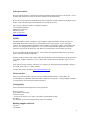
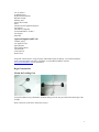
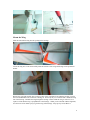
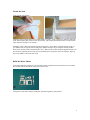
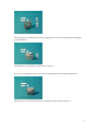
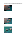
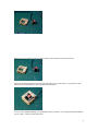
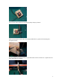
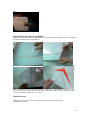
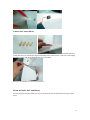
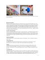
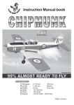
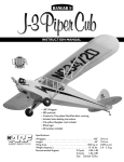
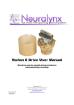
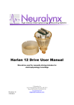
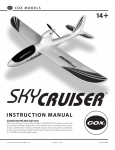
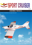
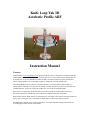
Knife Loop Yak 3D
Aerobatic Profile ARF
Instruction Manual
Warranty
Merlin Hobbies (www.merlinhobbies.com) guarantees this kit to be free from defects in both material and
workmanship at the date of purchase. This warranty does not cover any component parts damaged by use
or modification. In no case shall Merlin Hobbies liability exceed the original cost of the purchased kit.
Further, Merlin Hobbies reserves the right to change or modify this warranty without notice.
Since Merlin Hobbies has no control over the final assembly or material used for final assembly, no
liability shall be assumed, nor accepted for any damage resulting from the use by the user of the final user
assembled product. By the act of using this product, the user accepts all resulting liability.
If the buyer is not prepared to accept the liability associated with the use of this product, the buyer is
advised to return this kit immediately in new and unused condition to the place of purchase.
While this kit has been flight tested to exceed normal use, if the plane will be used for extremely high stress
flying, such as racing, the user is responsible for taking steps to reinforce the high stress points.
Read through this manual before starting construction. It contains important warnings and instructions
concerning the assembly and use of this model.
Safety precautions
Be aware that this model is a sophisticated working model that functions much like a real aircraft. Correct
assembly and operation are critical to the safety of both yourself and spectators.
Be sure to get experienced, knowledgeable help from an instructor with the construction and flight of your
model. Your local hobby shop has information on local clubs in your area.
Also you may contact the Academy of Model Aeronautics
5151 East Memorial Drive
Muncie, IN 47302-9252
PH 800-435-9262
FAX 765-741-0057
www.modelaircraft.org
INTRO
The Merlin Hobbies Sunny-Craft Knife Loop Yak ARF is a high performance sport aircraft with very
stable flight characteristics allowing even intermediate pilots to enjoy flying it. It is not a beginner
airplane. We cannot recommend the Knife Loop Yak ARF as your first R/C airplane. This airplane does
not recover to straight and level flight on it’s own. If you are able to handle a good basic trainer and a
small low wing aircraft, the Knife Loop Yak ARF is an excellent choice to learn about sport flying.
Be sure to build the model straight and true. Use first class radio equipment and the correct size motor,
wheels, fuel tank, and other components.
Properly test the operation of the controls and inspect the model for structural damage on the ground before
every flight. Replace connectors, clevises, cables, horns, and any other parts that show signs of wear or
fatigue.
If any parts are broken, missing, or defective or if you have any questions during the building or flying of
this model, please call us at 1-(920) 242-8623.
You may also email us at product [email protected].
Motor selection
There are several motors that will work well in your Merlin Hobbies Knife Loop Yak ARF. We
recommend the 2815 Brushless Outrunner from E3 and the E3 25 Amp ESC. Using an 800mah-1650mah
3 cell lipo battery will result in good 3D characteristics.
Getting Ready
Select a build area and carefully look over the supplied kit.
Be sure you have:
Four channel or more radio.
Four micro servos.
“Y” harness for aileron servos, unless your radio is programmable for flaps.
One motor.
One Propeller, see the motor instructions for proper size and pitch.
Building Supplies and Tools
CA Thin
CA Medium
2
CA Accelerator
30 Minute Epoxy
Hobby Knife and blades
Builders Triangle
Masking Tape
Electric Power Drill
Pliers
Filament used for alignment purposes
Screwdrivers
Threadlock Compound
Assorted Drill Bits 1/16 thru ½
Felt Tip Pen
Metal File
Optional Supplies and Tools
6 Minute Epoxy
CA Applicator Tips
Epoxy Brushes
Epoxy Mixing Sticks
CA Debonder
Trim Seal Tool
Dremel Tool
Inspect the control surfaces, wings, fuselage, and included parts for damage. If you find any damage
please return the model to the place of purchase or contact Merlin Hobbies customer
[email protected] for replacement.
Begin Construction
Mount the Landing Gear
Using the included o-ring to hold them, mount the main gear in the slot provided in the bottom edge of the
fuselage.
Drill 1.3mm hole on the fuse to mount the real gear.
3
Mount the Wing
Slide the unassembled wing into the opening in the fuselage.
Locate the wing at its center and carefully mark the interface of the wing and fuselage with a permanent
marker.
Remove the wing and carefully trim out the covering of the wing that will be under the fuselage. Expose
the wood underneath but be careful not to damage it. Trim away any cover material that is inside the wing
slot of the fuselage. Reinstall the wing through the fuselage. Recheck that the wing is centered. Use a
square to check that the wing is perpendicular to the fuselage. When you are satisfied with the alignment,
use a thin coat of 30 minute epoxy to glue the wing in the fuselage. Wipe up any excess adhesive.
4
Mount the Stab
Trim open the stab opening.
Adjust the stab in position until you are satisfied that it is square. Using a felt tip pen, mark the underside
of the stab along the edges where it meets the fuselage. Slip it back out and trim out the covering on both
sides where the fuselage covers the stab
Mount the wings at this time and slide the stab back in place. Check that it is parallel with the wings. If
you find that it is not, slip the stab out and gently sand the fuselage away to bring the stab into parallel.
Work slowly and do not take much material at once. When you are satisfied with the alignment, make sure
the elevator is installed, and use a thin coat of 30 Minute Epoxy to glue the stab in the fuselage. Wipe up
any excess adhesive and set the fuse aside.
Build the Motor Mount
Using the included plywood pieces you will build a frame to hold the motor onto the front of your model.
Be sure that your kit includes all of the pieces shown below.
Using the two side frames and the round plate, lock them together as shown below.
5
Next, align the center opening of the smooth rectangular plate, to the center opening of the rounded plate
you just assembled.
Glue both pieces in position with a small amount of Thin CA.
Next, lay the T-shaped piece on top of the ones you just glued with the tabs aligned in the notches.
The last three pieces of the frame fit into the remaining slots and notches to build a box.
6
Trim the airframe of the model as shown below. This will allow the finished assembly to slide into
position.
Test fit the motor mount on the airframe.
The 2815 motor comes with a double sided shaft and the “can” end must be trimmed to fit in the motor
housing.
Using a small hex wrench, loosen the locking sleeve from the motor shaft.
7
Remove the sleeve and put it aside, the motor mount you have just built will replace the lock.
Slip the motor shaft through the center opening and roll the motor into the frame. You may have to trim
back the inside of the frame to let the large motor drop into place.
Use two of the supplied mounting screws to hold the motor in position. Use locking compound to hold the
screws in place. Do not omit the thread lock.
8
This is how the final assembly looks with the prop adapter and prop mounted.
Slide the mount into the airframe and use the small predrilled holes as guides to drill mounting holes
through the airframe.
Pass the included bolts through the holes you just drilled and secure them with the nuts. Tighten and secure
them with thread lock compound.
9
Done.
Install the Control Surfaces and Rudder
Most of the control surfaces have been pre slotted. If you find that hinge strips do not go in or are difficult
to install, use a hobby knife to open them up.
Drill a 3/32” hole in each slot to allow CA to wick better into the hinges. Insert the hinge strips keeping
them centered in the opening and carefully align the control surface. Add six drops of Thin CA to each
side of each hinge strip. Allow the CA to cure slowly. After the CA has cured, move the control surfaces
several times to make sure they are easy to move.
Install the Servos
Trim the covering to open the servo openings in the belly and the tail of the fuselage.
And install servos in all.
10
Connect the Control Horns
Carefully select the mounting area for each control horn. The horn should be in line with the control rod
coming from the servo arm and also align with the hinge of the control surface. Take care to slot straight
through the surface and slip the horns into the slot you just made.
Glue them in with Thin CA. Do not use accelerator.
Mount the Radio, ESC, and Battery
Use hook and loop material to hold your receiver and electronic speed control under the wing as shown
below.
11
Use hook and loop material to hold the battery on the other side of the fuselage as shown below. This will
help with balancing.
Balance the Model
With the plane fully assembled and no fuel, lift the plane by the wings and check the balance point. The
center of gravity should be on the main spar that can be seen through the wing covering 1/3 back along the
wing root. Adjust the CG by adding stick on lead weights to the tail or the firewall as necessary. The CG
may be moved forward or back up to ½”. Do not attempt to fly the model if is not balanced as it will be
unstable and possibly uncontrollable. Balance the model laterally. With the model on a flat surface, lift it
quickly by the prop shaft and the tail. If one wing consistently drops, that side is heavy. Balance the plane
by adding weights to the lighter side.
Set the Control Throws
Turn on your transmitter and connect the battery to your speed control. Confirm that all controls operate in
the correct directions and as expected. Adjust your radio end points to achieve your desired throws. The
servos should move smoothly through their full range, without any excess noise. If the servos are straining
at the end of their travel, they will consume more battery power than expected, possibly shortening your
flight times.
Identify the Model
Label your model with your name and phone number or AMA number. This is an AMA policy and just
good practice.
Charge Batteries
Be certain that your transmitter and airplane batteries are fully charged. A weak battery can cause
unexpected or even complete loss of control. Be certain your batteries are fully charged.
Flying
Select a flying area that is large and grassy. School yards are not usually a good idea because of the
proximity of people and buildings. It should be at least 6 miles from buildings, streets and other RC
activities. The best place is at a sanctioned AMA club field. Contact the AMA for information on clubs
near you.
Ground Check
While still on the ground it is vital that you inspect your model for airworthiness. Double check all screws
and bolts for tightness. Check that control surfaces are secure. Check that the wing is secured and in place
correctly. Check the motor is in good working order. Confirm that the landing gear is secure. Check the
CG. When you are satisfied with the condition and assembly of the model proceed to the next step.
12
Range Check
At the field, ensure that your radio channel is not occupied and that it is safe to turn on your radio. Apply
power to your radio transmitter, then to your model’s receiver. Verify that all controls are working as
intended and the control surfaces move freely. With your antenna recessed, you should be able to walk up
to 50 feet (15 meters) away and still maintain glitch-free control. If not, stop and solve the problem. Do
not try to fly your model unless it is working glitch-free. Extend your transmitter.
13