1
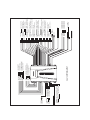
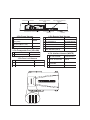
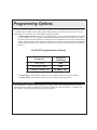
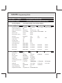
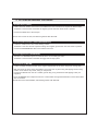
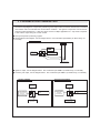
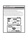
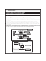
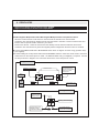
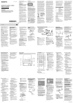
CA 670 Installation Instructions
PROFESSIONAL INSTALLATION STRONGLY RECOMMENDED
Installation Precautions:
Roll down window to avoid locking keys in vehicle
during installation
Avoid mounting components or routing wires near
hot surfaces
Avoid mounting components or routing wires near
moving parts
Tape or loom wires under hood for protection and
appearance
Use grommets when routing wires through metal
surfaces
Use a Digital Multi Meter for testing and verifying
circuits. DO NOT USE A TEST LIGHT, OR
"COMPUTER SAFE PROBE" as these can set off air
bags or damage vehicle computers.
FCC COMPLIANCE
This device complies with Part 15 of the FCC rules and with RSS-210 of Industry Canada.
Operation is subject to the following two conditions:
1. This device may not cause harmful interference, and
2. This device must accept any interference received, including any interference that may cause
undesired operation.
Warning! Changes or modifications not expressly approved by the party responsible for
compliance could void the user’s authority to operate the equipment.
(-) PULSE BEFORE START
(-) PULSE AFTER START
(-) PULSE AFTER SHUTDOWN
(-) PULSE DURING CRANK
BLUE/GREEN
(-) 2ND STAGE UNLOCK
NEGATIVE LOCK/POSITIVE UNLOCK
NEGATIVE UNLOCK/POSITIVE LOCK
GREEN
BLUE
TRANSPONDER PORT
Lt GREEN/BLACK
Lt.BLUE
BLACK/RED
BLACK/YELLOW
SAFETY
CONTROL
SWITCH
(-) ACTIVE OUTPUT
(+) BRAKE INPUT
(+) IGNITION 2 OUTPUT
(+) ACCESSORY 2 OUTPUT
(+) ACCESSORY 1 OUTPUT
(+)12 VOLTS BATTERY
CA-670 SYSTEM LAYOUT
(+) IGNITION 1 INPUT/OUTPUT
PINK
(+) STARTER OUTPUT(MOTOR SIDE)
PURPLE
(+) STARTER INPUT(KEY SIDE)
GREEN
(+) 12 VOLTS BATTERY
RED
30 AMP
BLUE/BLACK
BROWN/RED
PINK/WHITE
ORANGE/WHITE
ORANGE
RED
30 AMP
UNLOCK SENSE INPUT
PURPLE
BLACK/GRAY
Lt GREEN/ORANGE
BROWN/WHITE
16
17
18
19
ARMED OUTPUT (-)
TACH INPUT
HORN OUTPUT (-)
CHANNEL 1 (TRUNK)
PARKING LIGHT OUTPUT
SIREN OUTPUT (+)
GROUND
NEGATIVE DOOR TRIGGER
TRACKING PORT
PINK/RED
PINK/BLUE
PINK/GREEN
PINK/BLACK
ANTENNA /
RECEIVER
(-) CHANNEL 5 OUTPUT
(-) CHANNEL 4 OUTPUT
(-) CHANNEL 3 OUTPUT
(-) CHANNEL 2 OUTPUT
EXTERNAL SENSOR PORT
LED
VALET/
OVERRIDE
ORANGE
OPEN
15
22
SONGBIRD OUTPUT (-)
Lt BLUE/BLACK
14
PURPLE/ WHITE
HEADLIGHT OUTPUT (-)
PINK
13
21
WAIT TO START INPUT (-)
WHITE
12
BROWN/BLACK
OPEN
POSITIVE DOOR TRIGGER
BROWN
11
20
MANUAL DISARM INPUT
BLACK
10
PARKING BRAKE INPUT (-)
GREEN
9
HOOD PIN INPUT (-)
GRAY
GRAY/BLACK
REMOTE START ACTIVATION (-)
INSTANT TRIGGER INPUT (-)
TRUNK PIN INPUT(-)
8
WHITE/BLUE
DOME LIGHT OUTPUT
MANUAL ARM INPUT
7
BLUE/WHITE
BLUE
4
6
Lt BLUE/GREEN
3
5
BLACK/WHITE
Lt BLUE/RED
1
2
CA 670 System Layout
4-Pin Tracking Port 4-Pin Auxilliary Port
(Green])
(White)
4-Pin Receiver Port
(Black)
2-Pin LED Port
(White)
4-Pin External Sensor Port
(Tan)
4 Pin Auxiliary Harness (GREEN)
22-Pin Base Harness
2-Pin Valet Port
(Blue)
22 Pin Base Harness
1 C H AN N EL 2
PIN K /B LAC K
1
2 C H AN N EL 3
PIN K /GR EEN
2
MANUAL ARM INPUT
LT.BLUE/RED
3 C H AN N EL 4
PIN K /B LU E
3
UNLOCK SWITCH INPUT
LT.BLUE/GREEN
4
TRUNK PIN
B LU E
4 C H AN N EL 5
PIN K /R ED
5
INSTANT TRIGGER
BLUE/WHITE
6
REMOTE START
ACTIVATION
WHITE/BLUE
7
HOOD PIN INPUT
GRAY
8
PARKING BRAKE
GRAY/BLACK
9
NEGATIVE DOOR
TRIGGER
GREEN
10
GROUND
BLACK
11
POSITIVE SIREN OUTPUT
BROWN
12
PARKING LIGHTS
WHITE
13
CHANNEL 1
PINK
14
MANUAL DISARM INPUT
LT.BLUE/BLACK
4 Pin 2nd Sensor Port (TAN)
1 PR EWAR N
B LU E
2 FU LL TR IGGER
D K . GR EEN
3 GR OU N D
B LAC K
4 12 VOLTS
R ED
DOME LIGHT OUTPUT
BLACK/WHITE
15
16
POSITIVE DOOR TRIGGER PURPLE
17
WAIT TO START
BLACK/GRAY
18
HEADLIGHT OUTPUT
LT.GREEN/ORANGE
19
SONGBIRD OUTPUT
BROWN/WHITE
20
HORN OUTPUT
BROWN/BLACK
21
TACH INPUT
PURPLE/WHITE
22
ARMED OUTPUT
ORANGE
4-Pin Power Harness
Remote Start Switch
(Red)
6-Pin Remote Start Harness
4-Pin Interface Port
(White)
4 Pin Power Harness
1 + 12 VOLTS
2
3
2-Pin Transponder Port
(Yellow)
3-Pin Door Lock Port
(White)
6 Pin Remote Start Harness
R ED
1 + 12 VOLTS
R ED
2 AC C ESSORY 1
OR AN GE
3 AC C ESSORY 2
OR AN GE/WH ITE
STAR TER IN PU T
(K eyside)
GR EEN
STAR TER
OU TPU T(Motor Side)
P U R P LE
4 IGN ITION 2
PIN K /WH ITE
PIN K
5 B R AK E IN PU T
B R OWN /R ED
4 IGN 1 Input/Output
6
2 Pin Transponder Port (YELLOW)
1 GR OU N D OU TP U T
B LU E /B LAC K
2 12 VOLTS
R ED
AC TIVE R EMOTE STAR T
(R S) OU TPU T (IGN 3)
4 Pin Interface Harness (WHITE)
1
3 Pin Door Lock Harness
PU LSE B EFOR E STAR T
(FAC TORY D ISAR M)
2 PU LSE AFTER STAR T
1
N EG LOC K /POS U N LOC K
GR EEN
2
N EG U N LOC K /POS LOC K
B LU E
3
3
2N D STAGE U N LOC K
B LU E/GR EEN
4 PU LSE D U R IN G C R AN K
Fuse Grid
+
-
+
+
Trunk Polarity
-
Parking Light Polarity
Dome Polarity
-
Recommend 15Amp
B LU E/B LAC K
PU LSE AFTER
SH U TD OWN
LT.GR EEN /B LAC K
LT.B LU E
B LAC K /R ED
B LAC K /YELLOW
Programming Options
RF Programmer
The RF Programmer allows you to customize the system to fit the individual needs of the consumer, using
a handheld device capable of transmitting system settings directly to the system control module. The RF
Programmer is broken down into three different programming banks.
1. RF Programmer Bank- The RF Programmer Bank allows you to set up the base features of the system
you are installing. It is very important to understand that the base features of this system can only be
programmed using the RF Programmer. Please refer to the chart below showing factory default settings
(bold) to determine what options need to be changed for your system. When using the RF Programmer
to select feature settings is very important to verify that the correct base features remain at the default
settings.
CA 670 RF Programmer Base Features
Feature
D efault
S etting
S ecuri ty
ON
Remote Start
ON
1 Way/2 Way TX
2 Way TX
2. Feature Bank 1- Feature Bank 1 allows you to turn On/Off customer convenience features.
3. Feature Bank 2- Feature Bank 2 allows you to turn On/Off remote start features.
Manual Feature Programming
After installation is complete it will be necessary to program certain system characteristics that can't be
programmed using the RF Programmer (Shock Sensor settings and Tach Idle Speed). In addition all of
the customer convenience features and remote start features.
RF Programmer
Selecting Programmable Features
1. Press the POWER button to turn the system ON.
2. Once powered up the MENU screen will be displayed.
3. Use the UP & DN arrows to scroll through the programmable features. Once you locate the desired
feature to change, press the > arrow to advance to the next screen. You should see the default
setting of the system
4. Press the SET button to scroll through the available settings. Once the desired setting is shown on
the screen, press the < to return to the feature chart selectable options or press SEND to transmit
to the system you are installing.
NOTE: You must access the RF receive bank on Option programming to SEND the selected information
to the CA670, please refer to the programming section on the next page.
Using the M1 function
The RF Programmer has a memory function that will allow you to store the 4 most common feature
settings.
Once you have selected the settings that you want to store press and hold M1 button for 3 seconds. A
menu will appear which will allow you to select the memory bank you wish to save the desired feature
setting into.
Press the SET button to store the setting into memory. The menu will display "Write to memory X"
To retrieve a stored feature setting, press and release the M1 button. A menu will appear that will allow
you to select the desired memory bank.
Press SET to retrieve the desired stored memory bank. The menu will display "Read from memory X"
CA 670- Programming Guide
Feature Bank 0 - 3 Chirps
Transmitter Programming
Feature Bank 1 - 4 Chirps
RF Programmer Receive Bank
Feature Bank 2 - 5 Chirps
Shock Sensor Programming (W/Transmitter Only)
Lite Touch Adjustment
Full Trigger Adjustment
Feature Bank 3 - 6 Chirps
Lock increases sensitivity, Unlock decreases sensitivity
Lock increases sensitivity, Unlock decreases sensitivity
1 LED Flash
2 LED Flashes
3 LED Flashes
4 LED Flashes
Extended Lock Pulse
1 Second
3.5 Seconds
1 Sec L, Dbl U/L
30 Sec Lk/1 Sec U/L
Ignition Controlled Lock
ON
OFF
Ignition Controlled Unlock
UNLOCK ALL
Driver Door Only
Headlights
Active w/ARM
Active w/DISARM Active w/BOTH
Passive Locks
Passive
Active
Passive/Active Arming
Passive
Active
Siren/Horn
Siren/Horn
Siren
Horn
Horn Output Timing
10mS
16mS
30mS
40mS
Custom Code
ON
OFF
2nd Step Unlock
ON
OFF
Chirp Delete from TX
ON
OFF
Trunk Output Timing
Push & Hold
20 Sec.
AUX 1 Timing
Push & Hold
10 Seconds
20 Seconds
Latched
AUX 2 Timing
Push & Hold
10 Seconds
20 Seconds
Latched
AUX 3 Timing
Push & Hold
10 Seconds
20 Seconds
Latched
AUX 4 Timing
Push & Hold
10 Seconds
20 Seconds
Latched
3 LED Flashes
4 LED Flashes
15 Minutes
20 Minutes
Feature Bank 4 - 7 Chirps
OFF
OFF
1 LED Flash
2 LED Flashes
RF Start Chirp
OFF
ON
Run Time
5 Minutes
10 Minutes
Running Lights
ON Steady
Flashing
Tach Mode
Tachless Mode
Tach Mode
Voltage Level
>.5V B4 Start
<.5V B4 Start
Crank Average/Crank Time
Averaging
Preset Time
Crank Time
.8 Seconds
1.0 Seconds
1.5 Seconds
2.0 Seconds
Gas/Diesel
Gas
10 Sec Delay
15 Sec Delay
20 Sec Delay
Trans Bypass O/P
while RS ON
During Start
Until IGN OFF
Temp Controlled Start
OFF
ON
Single/Double Pulse Start
Single BTN Press
Double BTN Press
1. SETUP & PROGRAMMING
Transmitter Programming (3 Chirps)
1. With the door open turn the ignition ON.
2. Press and hold the valet/override button.
3. Within 10 Seconds the system will chirp (3) three times.
4. Press any one button of each transmitter you wish to program.
5. The system will respond with 1 chirp for each accepted transmitter.
Pressing the override button at anytime during programming will advance to the next bank.
Note: This system has 1 button programming which programs all channels of the system.
RF Programmer Receive (4 Chirps)
Note: Using the RF Programmer, program all settings prior to following the steps below.
1. With the door open turn the ignition ON.
2. Press and hold the valet/override button.
3. Within 10 Seconds the system will chirp (3) three times (If in transmitter programming simply press
the valet/override button once to advance to the desired feature bank).
4. Press the valet/override button again, the system will chirp (4) Four times
5. Press SEND on the RF Programmer to set all features and Setting of this system.
6. The unit will flash the parking lights and emit (2) long chirps indicating a successful program.
Shock Sensor Programming (5 Chirps)
1. With the door open turn the ignition ON.
2. Press and hold the valet/override button.
3. Within 10 Seconds the system will chirp (3) three times (If in RF programming simply press the valet/
override button to advance to the desired feature bank).
4. Use the valet/override button to advance through each option bank. For shock sensor programming
advance to shock sensor programming bank which is (5) five chirps.
5. Use the transmitter OPT button to scroll through the selections in each feature bank.
6. Press transmitter LOCK button to increase sensitivity and transmitter UNLOCK button to decrease
sensitivity.
NOTE: There are 64 levels of adjustment for each option. Once the highest/lowest sensitivity are achieved, the
sire/horn will sound an extended pulse to notify that you are at the end of the scale. Decreasing sensitivity one
more step from the lowest end of the scale will shut that zone off.
Manual Feature Bank Programming 3 & 4 (6/7 Chirps) without RF programmer
1. With the door open turn the ignition ON.
2. Press and hold the valet/override button.
3. Within 10 seconds the system will chirp (3) three times (If in shock sensor programming simply
press the valet/override button to advance to the desired feature bank).
4. Use the valet/override button to advance through each option bank. For feature programming advance
Feature Bank 1 & 2 which is (6) six chirps and (7) seven chirps.
5. Use the transmitter OPT Button to scroll through the selections in each feature bank.
6. Press the transmitter LOCK Button to change the desired feature. The LED will flash indicating the
changed feature.
The system will remain in programming mode as long as the ignition is on and the door is
opened, there is no time limit. To exit programming turn the IGNITION OFF.
to
Programming Tach Rate
The unit will not operate unless tach is programmed or tachless option is turned ON. If an attempt is made to
start the vehicle via the remote start without first programming tach, the unit will flash the parking lights 7 times
indicating tach has not been learned and stored. If the tach rate is not properly programmed to the specific vehicle,
the unit may not realize that the vehicle is running in certain instances reengage the starter motor.
The Remote Start Unit will learn the tach rate of most vehicle's single coil, multiple coil packs, or single injector.
To learn tach.
1.
2.
3.
4.
5.
6.
7.
Turn the ignition key to the On position.
Press and release the valet/override button 3 times.
Immediately turn the ignition key Off.
Press and hold the valet/override button, then start the vehicle using the key.
When the unit senses the tach signal, the parking lights will begin to flash.
Allow the vehicle to settle to a norman idle speed.
Release the valet/program push-button switch. The parking lights will stay ON Solid indicating that the learned
tach signal is stored and the unit has exited tach learn mode.
NOTE: If the unit fails to learn tach rate due to an improper tachometer connection or a poor tach source, the
parking lights will not flash. To correct this situation, locate and connect the PURPLE/WHITE wire to the proper
tach signal, and then repeat the tach learn routine.
Tachless Mode
This unit has 2 types of tachless modes for your convenience:
1. Averaging - Averages the last 8 times the customer has cranked the vehicle and uses that value for the crank
output timing.
Note: When using this option you must crank the vehicle manually (1 Time) before the system will remote start.
2. Preset time - You can select the amount of time the unit cranks the vehicle. Refer to the Crank Average/Crank
Time.
1. 4 PIN MAIN POWER HARNESS
Battery Power (RED)
Locate the vehicle’s battery wire(s) at the ignition switch.
Verification: These wires will register voltage in all positions of the ignition switch.
Connect the RED wire to the vehicle’s battery wire.
Note: Remove all 30 Amp fuses until all connections are made.
12 volts Ignition Input/Output (PINK)
Locate the vehicle’s Ignition wire at the ignition switch.
Verification: This wire registers voltage when the key is turned to the ON (or RUN) position. The voltage
does not drop out when the key is turned to the START (or CRANK) position.
Connect the PINK wire to the vehicle’s Ignition wire.
This wire is also used for Ignition 1 Output.
Starter Input (Key Side) (GREEN)
Starter Output (Motor Side) (PURPLE)
Locate the vehicle starter wire.
Verification: This wire registers voltage only when the key is turned to the START position. Cut the vehicle
starter wire in half.
Verification after starter wire is cut:
• KEY SIDE of starter wire registers voltage when the key is turned to the START position.
• MOTOR SIDE of starter wire registers no voltage.
Connect the GREEN wire to the KEY SIDE of the vehicle starter wire at the ignition switch harness.
Connect the PURPLE wire to the MOTOR SIDE of the vehicle starter wire.
2. BASIC INSTALLATION - 22 PIN BASE HARNESS
Dome Light Supervision Output (+/-) (BLACK/WHITE)
Locate the vehicle’s dome light or pin switch wire
Verification: This wire will register positive voltage or ground when the vehicle's dome is turned ON. Typically
this wire is installed with the door trigger input wire. Refer to NEG/POS door input for reference.
To select Negative or Positive polarity output:
Refer to Fuse Placement Diagram below.
Positive Polarity Output
Negative Polarity Output
(+)
(+)
(-)
(-)
2. 22 PIN BASE HARNESS CONTINUED
Negative Door Input (GREEN)
Locate the vehicle’s dome light or door pin switch wire.
Verification: This wire will register ground (NEG) when the door is opened and the interior light is on. This
wire will register positive voltage when the door is closed and the interior light is off.
Connect the GREEN wire to the vehicle’s negative door input wire(s).
Positive Door Input (PURPLE)
Locate the vehicle’s dome light or door pin switch wire.
Verification: This wire will register positive voltage(POS) when the door is opened and the interior light is on.
This wire will register ground or "0" Volts when the door is closed and the interior light is off.
Connect the PURPLE wire to the vehicle’s negative door input wire(s).
Chassis Ground Source (-) (BLACK)
Connect the BLACK wire to a solid chassis ground point using a ring terminal and self tapping screw (not
supplied). Scrape away paint from the grounding point to ensure a good connection. The recommended
grounding point is a painted metal surface in the driver’s side kick panel area.
Note: Do not ground the BLACK wire with any other vehicle components.
Ground When Armed Output (-) 500mA (ORANGE)
This wire will show Ground when the system is Armed
This wire is used for controlling window modules or additional sensors
Headlight Output (-) 500mA (LT. GREEN/ORANGE)
Locate the vehicle’s headlight wire
Verification: This wire will register either positive voltage or ground when the headlights are turned on
Connect the LT. GREEN/ORANGE to the vehicles headlight wire if the system is negative. (LOW CURRENT
ONLY)
Connecting to a Positive Headlight Output
Fused +12 Volt
Battery Feed
87
Fused +12 Volt
Battery Feed
87a
85
86
30
To Vehicle Headlight
Wire
Lt. GREEN/ORANGE Headlight
Output From Control Module
2. 22 PIN BASE HARNESS CONTINUED
Hood Pin Input (-) (GRAY)
Install a Hood Pin Switch and connect to the GRAY wire. This connections is required for Remote Start
Verification: This wire when connected will register ground when the vehicle hood is opened.
Connect the GRAY wire to the hood pin.
Note: Be sure to loom the wire, and seal the grommet with 3M caulk.
Low Current Horn Output (-) 500mA (BROWN/BLACK)
Locate the vehicle’s horn wire at the steering column.
Verification: This wire will rest at positive voltage and register ground when the horn switch is pressed.
Connect the BROWN/BLACK wire to the vehicle’s horn wire.
Instant Trigger Input (-) (BLUE/WHITE)
This wire is a GROUND input for an external sensor or secondary pin switch.
Verification: This wire when connected will trigger the security system.
Siren Output (+) (BROWN)
Locate a suitable mounting location in the engine compartment for the siren, away from moving parts.
With the bell of the siren aiming downwards, secure the siren in place using self tapping screws, being
careful not do drill into any hoses, wiring or components.
Connect the BLACK siren wire to a chassis ground using a ring terminal and self tapping screw (not
supplied).
Route the BROWN siren output wire from the control module through the firewall and connect to the RED
wire on the siren.
Note: Be sure to loom the wire/wires, and seal the grommet with 3M caulk.
2. 22 PIN BASE HARNESS CONTINUED
Parking Light Output (+/-) (WHITE)
Locate the vehicle’s parking light wire at the vehicle light switch.
Verification: This wire will register positive voltage or ground when the vehicle parking light switch is turned
to the ON position.
Positive Polarity Systems:
Connect the WHITE wire to the vehicle’s parking light wire at the light switch. Refer to Fuse Placement
Diagram below.
Negative Polarity Systems:
Connect the WHITE wire to the vehicle’s parking light wire at the light switch. Refer to Fuse Placement
Diagram below.
Positive Polarity Output
Negative Polarity Output
(+)
(+)
(-)
(-)
Manual ARM input (LT. BLUE/RED)
This wire will ARM the security system when a POS or NEG pulse is applied to it from an external device.
Manual DISARM Input (LT. BLUE/BLACK)
This wire will DISARM the security system when a POS or NEG pulse is applied to it from an external device.
Unlock Switch Sense (LT. BLUE/GREEN)
This wire will prevent the system from disarming the security system when a POS or NEG pulse is applied to it
from an external device. This will prevent the system from disarming if it is pulsed at the same time as the LT.
BLUE/BLACK (Manual Disarm Input) wire.
For example: To prevent the system from disarming from the switch on the door. Connect this wire to the unlock
switch or passenger unlock motor wire
NOTE: Only required if using the factory keyless entry transmitter to arm/disarm this system.
2. 22 PIN BASE HARNESS CONTINUED
Song Bird Output (BROWN/WHITE) SB1 Accessory required
This wire controls the SB1 accessory (Not Included).
Connect this wire to one of the WHITE/BLACK wires from the SB1.
Trunk Pin Switch Input (-) (BLUE)
Connect the BLUE wire to an optional grounding type trunk pin switch.
Trunk Release Output (+/-) (PINK)
Locate the vehicle’s trunk release wire at the trunk release switch.
Verification: This wire will register either positive voltage or ground when the trunk release is activated.
Positive Polarity Systems:
Connect the PINK wire to the vehicle’s trunk release wire. Refer to Fuse Placement Diagram below.
Negative Polarity Systems:
Connect the PINK wire to the vehicle’s trunk release wire. Refer to Fuse Placement Diagram below.
Positive Polarity Output
Negative Polarity Output
(+)
(+)
(-)
(-)
Vehicle Tach Signal (PURPLE/WHITE)
Locate the vehicle’s ignition coil or fuel injector in the engine compartment.
Verification: Refer to Vehicle Wire Color and Location Chart for the wire color and location, or test using the
following procedure:
1. Set voltmeter to AC VOLTS.
2. Attach positive lead of a volt meter to a constant 12-volt source.
3. Attach negative lead of a volt meter to the wire to be tested.
4. Start the engine.
5. Have someone press on the gas pedal slightly as you monitor the meter. If connected to the correct wire,
the voltage reading will increase as the engine’s RPM increases.
Connect the PURPLE/WHITE wire to the negative side of the vehicle ignition coil or fuel injector.
2. 22 PIN BASE HARNESS CONTINUED
Parking Brake Input (GRAY/BLACK)
NOTE: The following connection is only required for Turbo Timer.
Verification: This wire will register ground when the vehicle is in PARK or NEUTRAL or if the PARKING
BRAKE is engaged
This wire must see ground for the vehicle Turbo Timer option to activate
External Start Trigger (-) (WHT/BLUE)
NOTE: The following connection is only required on a REMOTE START installation.
This wire will activate the Remote Start when a GROUND pulse is applied to it from an external device.
Wait-To-Start Input (-) (BLACK/GRAY)
Locate the Wait-To-Start light wire at the instrument panel.
Verification: This wire registers positive or negative voltage when the wait-to-start light illuminates.
For negative switching circuits follow diagram 1 below. An SPDT relay is required (model HDRLY).
Wait-To-Start Bulb
At Instrument Panel
BLACK/GRAY Wait-To-Start
Wire
1N4004 Diode
Vehicle Control Module
Ignition
For Positive switching circuits follow diagram 2 below. Use Code Alarm part HDRLY (an SPDT relay, not
included).
Chassis Ground
87
Wait-To-Start Bulb
At Instrument Panel
87a
85
86
30
Ground
BLACK/GRAY Wait-To-Start
Wire
Vehicle Control Module
3. 6 PIN REMOTE START HARNESS
Battery Power 1 (12 AWG) (RED)
Locate the vehicle battery wire(s) at the ignition switch.
Verification: These wires will register POS voltage in all positions of the ignition switch.
Connect the RED wire to the vehicle’s battery wire.
Note: Remove all fuses until all connections are made
IMPORTANT!
If the vehicle is equipped with more than one battery wire at the ignition switch, connect the RED
wire from the 4- pin harness and the 2nd RED wire to separate vehicle battery wires.
Accessory 1 (Heater/AC) Output (12 AWG) (ORANGE)
Locate the vehicle’s accessory wire at the ignition switch.
Verification: This wire registers voltage when the key is turned to the ON (or RUN) position, but not the ACC
(Accessory) position. The voltage drops out when the key is turned to the START (or CRANK) position.
Connect the ORANGE wire to the vehicle’s accessory wire.
Accessory 2 (Heater/AC) Output (12 AWG) (ORANGE/WHITE)
Locate the vehicle’s accessory 2 wire at the ignition switch.
Verification: This wire registers voltage when the key is turned to the ON (or RUN) position, but not the ACC
(Accessory) position. The voltage drops out when the key is turned to the START (or CRANK) position.
Connect the ORANGE/WHITE wire to the vehicle’s accessory 2 wire.
Ignition 2 Output (12AWG) (PINK/WHITE)
Locate the vehicle’s ignition 2 wire at the ignition switch (if equipped).
Verification: This wire registers voltage when the key is turned to the ON (or RUN) position, but not the ACC
(Accessory) position. The voltage does not drop out when the key is turned to the START (or CRANK)
position.
Connect the PINK/WHITE wire to the vehicle’s ignition 2 wire.
Brake Input/Shutdown (+) (BROWN/RED)
Locate the vehicle’s brake light wire at the brake pedal mounted switch.
Verification: This wire registers positive voltage when the brake pedal is pressed.
Connect the BROWN/RED wire to the vehicle’s brake light wire.
3. 6 PIN REMOTE START HARNESS CONT.
Active Output (-) 500mA (BLUE/BLACK)
The Active Output/Ignition 3 output wire provides a ground output when the remote start function is activated
and remains until 4 seconds after the remote start is shutdown. The Ignition 3 output wire can be used for
several functions listed below. If this wire will be used for multiple application's a 1 amp diode is required
in-line with the stripe facing the control module.
Factory transponder (coded key) bypass.
General Motors VATS bypass, see the diagram below. Use Code Alarm part HDRLY (an SPDT relay, not
included).
GM VATS
Resistor
87
Fused +12 Volt
Battery Source
87a
85
86
BLUE/BLACK ActiveOutput
Wire
30
VATS Wire #2, WHITE or VIOLET/WHITE
Matching Value
VATS Wire #1, WHITE or WHITE/BLACK
Ignition Switch
X CUT
VATS Control Module
Ignition 3 output, see the diagram below. Use Code Alarm part HDRLY (an SPDT relay, not included).
Accessory 2/3 output, see the diagram below. Use Code Alarm part HDRLY (an SPDT relay, not included).
Accessory 2/3 Output
Ignition 3 Output
Fused +12 Volt
Battery Source
Fused +12 Volt
Battery Source
87
87
Jump To PINK
Ignition Output
Wire From
Control Module
87a
85
86
30
To Vehicle's2nd or 3rd
Ignition Wire
BLUE/BLACK ActiveOutput
Wire
Jump To ORANGE
Accessory Output
Wire From
Control Module
87a
85
86
30
To Vehicle's2nd or 3rd
Accessory Wire
BLUE/BLACK ActiveOutput
Wire
4. 4 PIN REMOTE START PULSED OUTPUTS
Factory Disarm/Pulse Before Start (-) 500mA (LIGHT GREEN/BLACK)
Locate the factory perimeter alarm disarm wire from the key cylinder inside the drivers door.
Verification: This wire registers ground if the key is turned to the unlock position in the driver’s door cylinder.
Connect the LIGHT GREEN/BLACK wire to the factory alarm disarm wire.
Pulse After Start (-) 500mA (LIGHT BLUE)
This wire is usually used to re-lock the vehicle’s doors upon remote start if necessary. See section 6 to
determine what type of door lock system the vehicle has.
Pulse After Shutdown (-) 500mA (BLACK/RED)
This wire is usually used to re-lock the vehicle’s doors if they unlock upon remote start shutdown. It can
also be used to pulse a door pin-switch wire to prevent the vehicle’s accessories from remaining on after
remote start shutdown.
Pulse During Crank (-) 500mA (BLACK/YELLOW)
Locate the vehicle’s second starter (crank) wire at the ignition switch. (if equipped)
Verification: This wire registers voltage only in the start (crank) position of the ignition switch.
Connect the BLACK/YELLOW wire as shown in the diagram below. Use Code Alarm part HDRLY (an SPDT
relay, not included).
Fused +12 Volt
Battery Source
87
Jump To VIOLET
Starter Output
Wire From The
Control Module
87a
85
86
30
To Vehicle's2nd
Starter Wire
BLACK/YELLOW Pulse
During Crank Wire
5. 4 PIN ADVANCE CHANNEL HARNESS
Channel 2 (-) 500mA(PINK/BLACK)
This wire provides a 500mA negative output capable of driving relays. For Control of optional accessories
(i.e. Power Window/Sunroof,etc.).
To Activate press and hold LOCK & TRUNK. Please refer to the selectable options for timing.
Selectable timing: Push & Hold/10 Seconds/20 Seconds/Press to Latch ON/Press to Latch OFF.
Channel 3 / Defrost Output (-) 500mA (PINK/GREEN)
Locate the vehicle’s rear window defrost wire.
Verification: This wire will register either positive voltage or ground when the rear defroster is turned on.
For Negative Polarity Systems:
Connect the PINK/GREEN wire to the vehicle defrost wire if the system is negative.
For Positive Polarity Systems:
If the system is positive, connect the PINK/GREEN wire as shown below. Use Code Alarm part HDRLY (an
SPDT relay, not included).
Fused +12 Volt
Battery Source
87
87a
85
86
Rear Defrost
Control Relay
ORANGE/RED Rear
PINK/GREEN
Defrost
Output Wire
30
To Rear Window
Defrost Grid
Note: This output is controlled by press & holding OPT for 2 Seconds
Selectable timing: Push & Hold/10 Seconds/20 Seconds/Press to Latch ON/Press to Latch OFF
Channel 4 (-) 500mA (PINK/BLUE)
This wire provides a 500mA negative output capable of driving relays. For Control of optional accessories
(i.e Power Window/Sunroof,etc.).
To Activate press and hold LOCK & OPT. Please refer to the selectable options for timing.
Selectable timing: Push & Hold/10 Seconds/20 Seconds/Press to Latch ON/Press to Latch OFF.
Channel 5 (-) 500mA (PINK/RED)
This wire provides a 500mA negative output capable of driving relays. For Control of optional accessories
(i.e Power Window/Sunroof,etc.).
To Activate press and hold UNLOCK & OPT. Please refer to the selectable options for timing.
Selectable timing: Push & Hold/10 Seconds/20 Seconds/Press to Latch ON/Press to Latch OFF.
6. DOOR LOCKS
Negative Lock Output / Positive Unlock Output (GREEN)
Negative Unlock Output / Positive Lock Output (BLUE)
Negative Second Door Unlock Output (BLUE/GREEN)
The door lock / unlock outputs are designed to control several different types of systems which may require
additional parts. Please review the wire and location chart to see which type of door lock system is in your
vehicle. The most common types are shown in the diagrams below.
Negative Switching and Negative Switching with 2-step unlock feature:
All Door Lock and Unlock: Locate the lock / unlock wire at the vehicle’s lock / unlock switch.
Verification: These wires will register ground when the Lock and Unlock switches are activated.
Driver’s Door Unlock: Locate the unlock motor wire directly from the actuator inside the driver’s door.
Verification: This wire will rest at ground and register positive voltage when the driver’s door is unlocked.
Connect the GREEN and BLUE or BLUE/GREEN wires shown in diagram 6 below.
Note: When adding the 2 step unlock feature the BLUE/GREEN 2nd door unlock wire will be used to unlock
all vehicle doors on the second press of unlock. An additional SPDT relay (not supplied) is required.
Connect the relay as shown in diagram 7 to unlock the driver’s door on the first press of unlock.
Diagram 6
Door Lock Switch
GREEN (-) Lock Output
Lock
Vehicle Door Lock
Control Relays
Unlock
BLUE (-) Unlock Output OrBLUE/GREEN
BLUE/RED
(-) 2nd Door Unlock Output When
Installing The 2-step Unlock Feature
Diagram 7
Fused +12 Volt
Battery Source
87
87a
BLUE (-) Unlock Output
85
86
30
From Keyless Entry
Module Or Door
Lock/Unlock Relays
X
CUT
To Unlock Side Of
Driver's Door Actuator
6. DOOR LOCKS
Negative Lock Output / Positive Unlock Output (GREEN)
Negative Unlock Output / Positive Lock Output (BLUE)
Negative Second Door Unlock Output (BLUE/GREEN)
Positive Switching and Positive Switching with 2-step unlock feature:
All Door Lock and Unlock: Locate the lock / unlock wire at the vehicle’s lock / unlock switch.
Verification: These wires will register positive voltage when the Lock and Unlock switches are activated.
Driver’s Door Unlock: Locate the unlock motor wire directly from the actuator inside the driver’s door.
Verification: This wire will rest at ground and register positive voltage when the driver’s door is unlocked.
Connect the GREEN and BLUE or BLUE/GREEN wires shown in diagram 8 below.
Note: When adding the 2 step unlock feature the BLUE/GREEN 2nd door unlock wire will be used to unlock all
vehicle doors on the second press of unlock. Two additional SPDT relays (not supplied) are required.
Connect the relays as shown in diagram 9 to unlock the driver’s door on the first press of unlock.
Diagram 9
Fused +12 Volt
Battery Source
87
Door Lock Switch
87a
BLUE (+) Lock Output
85
86
30
Lock
Vehicle Door Lock
Control Relays
Unlock
Fused +12 Volt
Battery Source
87
Chassis Ground
GREEN (+) Unlock Output
87a
85
86
30
From Keyless Entry
Module Or Door
Lock/Unlock Relays
X
CUT
To Unlock Side Of
Driver's Door Actuator
BLUE/GREEN 2nd
Door Unlock Output
6. DOOR LOCKS
Negative Lock Output / Positive Unlock Output (GREEN)
Negative Unlock Output / Positive Lock Output (BLUE)
Negative Second Door Unlock Output (BLUE/GREEN)
Reverse Polarity (5-Wire Doorlocks) and Reverse Polarity with 2-step Unlock
All Door Lock and Unlock: Locate the lock / unlock wire at the vehicle’s lock / unlock switch.
Verification: These wires will rest at ground and register positive voltage when the Lock and Unlock switches
are activated.
Driver’s Door Unlock: Locate the unlock motor wire directly from the actuator inside the driver’s door.
Verification: This wire will rest at ground and register positive voltage when the driver’s door is unlocked.
Connect the GREEN and BLUE or BLUE/GREEN wires shown in diagram 10 below using (2) SPDT relays
(not supplied).
Note: When adding the 2 step unlock feature the BLUE/GREEN 2nd door unlock wire will be used to unlock all
vehicle doors on the second press of unlock. An additional SPDT relay (not supplied) is required. Connect
the relays as shown in diagram 11 to unlock the driver’s door on the first press of unlock
Diagram 10
Fused +12 Volt
Battery Source
87
Master Door
Lock Switch
87a
GREEN (-) Lock Output
85
86
30
Lock
To Door Lock
Actuators
X
Cut
Unlock
Fused +12 Volt
Battery Source
87
87a
85
86
BLUE (-) Unlock Output
Or BLUE/GREEN(-) 2nd
Door Unlock Output
30
To Door Lock
Actuators
X
Cut
Diagram 11
Fused +12 Volt
Battery Source
87
87a
BLUE (-) Unlock Output
85
86
30
From Keyless Entry
Module Or Door
Lock/Unlock Relays
X
CUT
To Unlock Side Of
Driver's Door Actuator
6. DOOR LOCKS
Negative Lock Output / Positive Unlock Output (GREEN)
Negative Unlock Output / Positive Lock Output (BLUE)
Negative Second Door Unlock Output (BLUE/GREEN)
One Wire Negative Multiplexed and One Wire Negative Multiplexed with 2-step Unlock Feature:
All Door Lock and Unlock: Locate the lock / unlock wire at the vehicle’s lock / unlock switch.
Verification: This wire will show variable ground when the switch is activated. Please consult the wire and
location chart for specific resistor values for your vehicle.
Driver’s Door Unlock: Locate the unlock motor wire directly from the actuator inside the driver’s door.
Verification: This wire will rest at ground and register positive voltage when the driver’s door is unlocked.
Connect the GREEN and BLUE or BLUE/GREEN wires shown in diagram 12 below using (2) SPDT relays
(not supplied).
Note: When adding the 2 step unlock feature the BLUE/GREEN 2nd door unlock wire will be used to unlock all
vehicle doors on the second press of unlock. An additional SPDT relay (not supplied) is required. Connect
the relay as shown in diagram 13 to unlock the driver’s door on the first press of unlock.
Diagram 12
GREEN (-) Lock Output
BLUE (-) Unlock Output
Or BLUE/GREEN 2nd
Door Unlock Output When
Installing The 2-Step
Unlock Feature
Chassis Ground
87
87
Door
Lock Switch
87a
85
86
Fused +12 Volt
Battery Source
87a
30
30
Lock
85
86
Resistor
Resistor
Vehicle Door Lock
Control Relays
Unlock
Diagram 13
Fused +12 Volt
Battery Source
87
87a
BLUE (-) Unlock Output
85
86
30
From Keyless Entry
Module Or Door
Lock/Unlock Relays
X
CUT
To Unlock Side Of
Driver's Door Actuator
6. DOOR LOCKS
Negative Lock Output / Positive Unlock Output (GREEN)
Negative Unlock Output / Positive Lock Output (BLUE)
Negative Second Door Unlock Output (BLUE/GREEN)
One Wire Positive Multiplexed and One Wire Multiplexed With 2-step Unlock Feature:
All Door Lock and Unlock: Locate the lock / unlock wire at the vehicle’s lock / unlock switch.
Verification: This wire will show variable positive voltage when the switch is activated. Please consult the
wire and location chart for specific resistor values for your vehicle.
Driver’s Door Unlock: Locate the unlock motor wire directly from the actuator inside the driver’s door.
Verification: This wire will rest at ground and register positive voltage when the driver’s door is unlocked.
Connect the GREEN and BLUE or BLUE/GREEN wires shown in diagram 14 below using (2) SPDT relays
(not supplied).
Note: When adding the 2 step unlock feature the BLUE/GREEN 2nd door unlock wire will be used to unlock all
vehicle doors on the second press of unlock. An additional SPDT relay (not supplied) is required. Connect
the relay as shown in diagram 15 to unlock the driver’s door on the first press of unlock.
Diagram 14
GREEN (-) Lock Output
Fused +12 Volt
Battery Source
87
87
Door
Lock Switch
87a
Fused +12 Volt
87a
85 Battery Source
86
85
86
30
30
Lock
BLUE (-) Unlock Output
Or BLUE/GREEN (-) 2nd
Door Output When
Installing The 2-Step
Unlock Feature
Resistor
Resistor
Vehicle Door Lock
Control Relays
Unlock
Diagram 15
Fused +12 Volt
Battery Source
87
87a
BLUE (-) Unlock Output
85
86
30
From Keyless Entry
Module Or Door
Lock/Unlock Relays
X
CUT
To Unlock Side Of
Driver's Door Actuator
6. DOOR LOCKS
Negative Lock Output / Positive Unlock Output (GREEN)
Negative Unlock Output / Positive Lock Output (BLUE)
Negative Second Door Unlock Output (BLUE/GREEN)
Adding Aftermarket Actuators
After installing aftermarket actuators, (not supplied). Connect the GREEN and BLUE wires shown in
diagram 16 below using (2) SPDT relays (not supplied).
Diagram 16
Fused +12 Volt
Battery Source
87
Door Lock
Actuator
87a
GREEN (-) Lock Output
85
86
30
Chassis
Ground
M
Fused +12 Volt
Battery Source
87
87a
BLUE (-) Unlock Output
85
86
30
Chassis
Ground
7. ACC. CONNECTOR'S
2 Pin Transponder Control Output: (Yellow Connector)
This output is intended to allow the control of a transponder bypass interface module or transponder
bypass relay.
2 Pin Control Switch: (Red Connector)
The BLACK and BLACK/WHITE wires loaded in the two pin red connector enable the operation of the
Remote Start unit. When the Black w/ White Trace wire is grounded, the remote start unit is operable.
When this wire is open from ground, the remote start is disabled. Drill a 1/4" hole and mount this switch in
an easily accessible location under the driver's dash. This switch needs to be installed for remote start to
function
2 Pin Valet/Program/Override Push-Button Switch: (Blue Connector)
The BLACK and GRAY twin lead wires loaded in the two pin blue connector are the ground supply and
program/valet/override input of the Remote Start unit. Drill a 9/32" hole and mount this switch in an easily
accessible location under the driver's dashboard.
4 Pin Antenna/Receiver Connector: (Black Connector)
Mount the supplied antenna/receiver to a clear spot on the vehicle's winshield that will not block the
driver's vision. A good location is usually high on the winshield near the rear view mirror. Be carefule not
to mount the antenna/receiver on any metallic window film, as this will effect system range. Route the
antenna/receiver cable to the control module and plug in to the 4 pin black connector.
4 Pin 2nd Shock Sensor Port: (White Connector)
The RED (+12 volt), BLACK (ground), BLUE (pre-detect) and GREEN (full trigger when armed) wires
loaded into the white connector shell are the inputs/outputs of the shock sensor.
2 Pin LED Harness: (White Connector)
The RED & BLUE wires loaded into the two pin mini white connector control the anode and cathode of the
dash mounted LED. Drill a 1/4" hole and mount the LED in an easy to see location on the dashboard. Be
careful to check to make sure that there is enough clearence behind the panel you are drilling into.
8. SYSTEM POWER-UP PROCEDURE
1. After all connnections are complete, turn the vehicle's ignition key to the ON position.
2. Insert both 30 Amp fuses into their respective fuseholders.
3. Turn the ignition key to the OFF position.
9. System Testing
1. Follow each instruction below.
2. Verify that the system operates as indicated under each instruction. Refer to the system owners manual.
3. Check the appropriate wire connection(s) and/or fuse(s) if the unit fails to perform a specific function.
Also check that any options pertaining to the function are programmed properly.
Security Operation
Press LOCK once:
1. Doors lock.
2. Courtesy lights (if on) shut off.
3. Unit checks to see if doors, hood or trunk are open. If open, siren (or horn) sounds once, parking lights
flash once, and system enters pre-arm mode.
Pre-arm mode:
1. The unit will wait for the open door, hood or trunk to be closed. The LED is solid during pre-arm.
2. If the entrance is secured, the siren/horn will sound again, parking lights will flash once, and the system
will arm.
3. If the entrance is not secured after 4 minutes, the siren/horn will sound again, parking lights will flash
once, the system will arm, and the defective trigger or entrance will be ignored.
Note: If entrance is secured after 4 minutes, the system will immediately begin to monitor the entrance for
intrusion.
If the above conditions are not present:
1. Vehicle starter is disabled.
2. Siren (or horn) sounds twice / parking lights flash twice.
3. The LED flashes slowly for duration of arm cycle.
4. After 5 seconds, unit monitors all entrances and sensors.
If door, sensor, hood/trunk or ignition input is triggered:
1. Siren/horn sounds for 30 seconds or until UNLOCK is pressed.
2. Parking lights flash
3. If the system is triggered, pressing DISARM (once) will end the 30-second cycle.
The LED flashes a number of times to indicate which input triggered the alarm:
Number of flashes:
1 - Interior Theft Sensor (Shock Sensor)
2 - Hood/Trunk input
3 - Door Input
9. System Testing Cont.
Press DISARM:
1. Doors unlock.
2. Factory alarm (if equipped) is turned off.
3. Siren/horn sounds once/ parking lights flash once.
4. Courtesy lights turn on for 30 seconds, or until ARM is pressed or ignition is turned on.
5. Vehicle starter is enabled.
.
Press DISARM twice:
1. Passenger doors unlock if using 2-stage unlock.
Press FIND:
Siren/horn sounds 5 times.
Press and hold PANIC for 2 seconds:
Siren/horn sounds and lights flash for 30 seconds or until any remote control button is pressed.
Press and hold TRUNK:
Trunk or hatch opens, or other device activates.
If Ignition Lock option is set to On:
Doors lock when all doors are closed and key is turned to ON position.
If Ignition Unlock option is set to On:
Doors unlock when ignition is turned off.
Remote Start Operation (if equpped)
Press then press START button twice within 2 seconds. (single press start is selectable)
1. Unit will flash 7 times if tach is not yet learned.
2. Unit will flash 4 times if the remote start saftey switch is not installed
If the above conditions are not present:
1. Parking lights flash once.
2. Factory alarm (if equipped) is turned off.
3. Factory VATS or PATS systems (if equipped)
are interfaced (active output is activated).
4. Interior Sensor is disabled.
5. Vehicle ignition turns on.
6. Heater/AC are powered.
7. Vehicle starter begins to crank (heater/AC power shuts off while vehicle starter is cranking).
8. Vehicle successfully starts.
9. Vehicle will shut off if hood is opened, brake is pressed, or if engine reaches 3 times its idle speed
(Tach Sense Mode only).
11. Parking lights stay on (or flash if selected) for duration of run time.
12.Heater/AC is powered for duration of run time.
10. Mounting the Module / Finishing the Installation
1. Mount the module to a brace or wire harness under the dash. The module and harnesses must be clear of
moving parts.
2. Completely uncoil the antenna and route up the nearest front window pillar to the headliner. Be careful not
to pinch the antenna under vehicle panels, or route near moving parts.
3. Route the antenna across the headliner to a position behind the rearview mirror.
4. Attach the antenna to the inside of the windshield behind the rearview mirror:
• The glass surface must be clean before mounting antenna. Use rubbing alcohol to thoroughly clean the
mounting location.
• Remove protective backing and press firmly against windshield.
5. Plug antenna into the Reciever Plug located in the back of module. (Black Connector)
Installation Complete.