1
.,
-=::::::::
r'
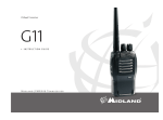
uniden
"
AX 144 CB RADIO
OWNERS MANUAL
---.
--
-----
n
---
--
-.
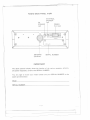
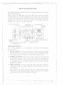
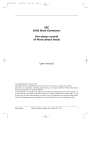
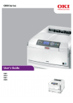
RADIO BACK PANEL VIEW
PA
SPEAKER
Jack
@
0
EXTERNAL
SPEAKER
Jack
POWER
Cord Jack
0
@
@
ANT
@
SERIAL,NO
SERIAL NUMBER
ANTENNA
Connector
I MPORT ANT!
The above pictorial
display shows the location
and power receptacles, as well as the SERIAL
You are urged to record your
spaces provided below:
of the various accessory, antenna,
NUMBER.
model number and your SERIAL
NUMBER
in the
Model
SERIAL NUMBER
-1-
L
}
-. - -
---
----
--
~.n
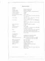
SPECIFICATIONS
GENERAL
Channels
Frequency Range
Frequency Control
Frequency Tolerance
Frequency Stability
Operating Temperature Range
Microphone
Input Voltage
Current Drain
Cabinet Dimensions
Weight
Antenna Connector
Semiconductors
Meter
Indicators
40 AM, 40 LSB, 40 USB
26.965 to 27.405 MHz
Phase Locked Loop(PLL) synthesized circuitry
:to.005%
0.001 %
-10°C to +50°C
Plug-in type; dynamic with push-to-talk switch
and coiled cord
13.8V DC nominal, 15.9V max., 11.7V min.
(positive or negative ground).
Transmit: AM full mod., 2.2A; SSB Maximum
output,2A.
Receiver: AM & SSB with maximum audio
output, 0.6A.
7-9/32(W) x 9-5/64(0) x 2-9/32(H)
4.5 Lbs
UHF, SO-239
47 transistors, 5 integrated circuits, 66 diodes
and 6 light emitting diodes..
Illuminated; indicates relative power output and
received signal strength, green receive LED.
LED display; channel, emergency channel, TX/
RX and mode.
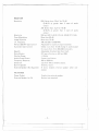
TRANSMITTER
Power Output
Modulation
Intermodulation
Distortion
SSB Carrier Suppression
Unwanted Sideband
Frequency Response
Output Impedance
SSB Filter
Output Indicators
AM,SSB Maximum Legal Output Power
AM, high and Iow level Class B
SSB: 3rd and 5th order, better than -25 dB.
7th and 9th order, better than -35 dB.
Better than -55 dB
Better than -50 dB
AM and SSB: 350 to 2500 Hz.
52 ohms, unbalanced
10.695 MHz, 8 pole monolithic type
6 dB @4.2 kHz
60 dB @ 7.0 kHz
Meter shows relative RF output power; red
transmit LED.
-2-
------
rj
,
RECEIVER
Sensitivity
Selectivity
Cross Modulation
Image Rejection
t.F. Frequency
AM and SSB RF Gain Control
Automatic Gain Control
Squelch
Noise Blanker
Clarifier Range
Audio Output Power
Frequency Response
Distortion
Built-in Speaker
External Speaker (Not Supplied)
SSB: Better than ,25 p V for 10 dB
(S+N)/N at greater than 1f2watt of audio
output
AM: Better than .5 pV for 10 dB
(S+N)/N at greater than 1f2watt of audio
output
SSB and AM: 6 dB @ 4.2 kHz, 60 dB @ 7.0 kHz
More than 50 dB
More than 75 dB
AM and SSB: 10.695 MHz
Adjustable for optimum signal reception.
(AGC): Less than 10 dB change in audio output
for inputs from 10 to 500,000 microvolts.
Adjustable; threshold less than .5 pV.
RF type, effective on AM and SSB.
::\:1.0kHz
3 watts into 8 ohms
350 to 2500 Hz
Less than 10% at 3 watts output.
16 ohms, round
8 ohms; disables internal speaker when connected.
PA SYSTEM
Power Output
External Speaker for PA
3 watts into external speaker.
8 ohms (not supplied)
-3-
-
I
---------
j
,
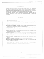
INTRODUCTION
UNIDEN has combined superb workmanship and modern styling with the very latest state-of-art circuitry to bring you the new AX 144 Citizens Band Transceiver.
It has been especially designed to give you maximum performance and reliability.
YourAX 144 is completely factory aligned and quality assurance tested.
To obtain the maximum benefit and pleasure from your AX 144 please read very
carefully the contents of this manual before attempting to install or operate the
transce~ver .
FEATURES
. ALL SOLID STATE: IC and Transistorized construction, with Iow current drain,
for a long, trouble-free life.
.
FULL 40-CHANNEL OPERATION: PLL frequency, synthesizer circuitry allows
transmission and reception on all 40-channels on AM, USB and LSBwithout the
purchase of any additional crystals.
.
LARGE LED CHANNEL DISPLAY: Channel number is displayed by use of LED
(light emitting diode) display for ease of channel selection.
. CLEAN SIGNAL: Transmitter audio processing circuitry produces a clean signal
with maximum legalmodulation, for best range.
. QUIET RECEPTION: Effective squelch and automatic noise limiter and an RF
noise blanker for superior quieting.
.
EFFECTIVE AGC: Receiver amplified automatic gain control (AGC) reduces the
effect of differences in received signal strengths. No distracting "blasting" and
"fading" of signals.
. AN EFFICIENT TRANSMITTER:Provides maximum legal output power to the
antenna.
. PUBLICADDRESSFUNCTION: Usefulfor paging and announcements.
. TRI-COLOR LED MODE INDICATOR: Green for AM mode, Yellow for USB
mode and Red for LSB mode.
.
EMERGENCY CH 9 SWITCH: This switch enebles you to select emergency
channel (CH 9) regardlessof the channel selector switch setting.
-4-
r
t
--
---
-
==
,
~
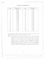
CHANNEL INFORMATION
Channel
1
2
3
-4
5
6
7
8
9
10
11
12
13
14
15
16
17
18
19
20
Channel Frequency
in MHz
Channel
Channel Frequency
in MHz
26.965
26.975
26.985
27.005
27.015
27.025
27.035
27.055
27.065
27.075
27.085
27.105
27.115
27.125
27.135
27. 155
27.165
27.175
27.185
27.205
21
22
23
24
25
26
27
28
29
30
31
32
33
34
35
36
37
38
39
40
27.215
27.225
27.255
27.235
27.245
27.265
27.275
27.285
27.295
27.305
27.315
27.325
27.335
27.345
27.355
27.365
27.375
27.385
27.395
27.405
To insure that you obtain the maximum performance from this radio, please read
carefully the following descriptions and operating instructions.
NOTE:
This radio has been designed for operation in the 11 meter Citizens Band
Radio Service. It uses a frequency synthesizing circuit with Phase Locked
Loop(PLL) techniques to provide crystal controlled transmit and receive
operation on all 40 channels. The PLL circuitry assures ultraprecise
frequency control. It is designed to meet the Department of Commu~
nication requirements applicable to equipment operating in the Citizens
Band Radio Service, and is not to be used for any other purpose. MS 312 of
the D.O.C. regulations defines operation in this service, and you are required
to read and understand these regulations prior to operating this equipment.
-5-
~
-
I
------- j
,
INSTAllATION
Location
Plan the location of the transceiver and microphone bracket before starting the
installation. Select a location that is convenient for operation and does not interfere
with the driver or passenger in the vehicle. In automobiles, the transceiver is usually
mounted to the dash panel with the microphone bracket beside it.
Mounting and Connection
This radio is supplied with a universal mounting bracket. The transceiver is held in
the bracket by the two thumb screws supplied, permftting adjustment to the most
convenient angle. The bracket must be mounted with the machine screws supplied.
The mounting surface must be mechanically strong. Proceed as follows to mount the
transceiver:
1. After you have determined the most convenient location in your vehicle, hold the
radio with mounting bracket in the exact location desired. If nothing interferes
with mounting it in the desired position, remove the mounting bracket bolts.
Before drilling the holes, make sure nothing will interfere with the installation of
the mounting bolts.
2. Connect the antenna cable plug to the standard receptacle on the rear panel. Most
CB antennas are terminated with a type PL-259 plug which mates with the
receptacle on the rear panel.
3. Connect the DC power input wire with the fuse (red) to +12V DC. This wire
extends from a plug which connects to the rear panel. In automobile installations,
+12V DC is usually obtained from the accessory contact on the ignition switch.
-6-
r
------
j
,
.-'--'
~=
This prevents the set being left on accidentally when the driver leaves the car and
also permits operating the radio without the engine running. You can locate the
accessory contact on most ignition switches by tracing the power wire from the
AM broadcast receiver in the car.
Note: See ground connection under GENERAL INFORMATION for more detail.
4. Connect the black wire to ground. This is usually the chassis of the car. Any convenient location with good electrical contact may be used. (remove paint).
5. Mount the microphone hanger on the side of the unit or near the unit, using two
screws supplied. When mounting in an automobile, place the hanger on the dash
so the microphone is easily accessible.
GENERAL INFORMATION
GROUND
CONNECTION
This radio may be installed and used in any 12V DC negative or positive ground
system vehicle. Most new U.S. and foreign made cars or small trucks use a negative
ground system while some older cars and some newer large trucks may use a positive
ground system.
1. Negative ground system: Connect the Red power lead from the radio to thepositive or (+) battery terminal or other convenient point, and connect the Black
power lead to the chassis or vehicle frame or (-) battery terminal.
2. Positive ground system: In the case of positive ground system, connect the Black
power lead from the radio to the negative or (-) battery terminal or other
convenient point, and connect the Red power lead to the chassis or vehicle frame
or (+) battery terminal.
ANTENNA
This radio is designed to operate into a 52 ohm CITIZENS RADIO antenna. Best
results will be obtained from your transceiver if you use a good antenna, properly
installed. (Refer to the antenna installation instructions included with your antenna.)
A vertically polarized quarter-wavelength whip antenna provides the most reliable
operation and greater range. The shorter loaded-type whip antennas are more attractive, compact and adequate for applications where the maximum possible distance is not required. Also, the loaded whip antennas do not present the problems of
height imposed by the full quarter-wavelength whip.
-7-
-.---
--
-----
r
Mobile whip antennas utilize the metal body of the vehicle as a ground plane. When
mounted on a corner of the vehicle, they are slightly directional, in the direction of
the body of the vehicle. For all practical purposes, however, the radiation pattern is
non-directional.
A slight directional characteristic wi 11be observed only at extreme
distances. A standard antenna connector
(Type SO-239) is provided on the
transceiver for easy connection to a standard PL-259 cable termination.
When installed in a boat, the transceiver will perform most
antenna used has been specifically designed for marine applications.
Before
installing
the
transceiver
regarding an adequate grounding
ings in the hull and water.
BASE STATION
in a boat, consult
system and prevention
your
efficiently
dealer for
when
information
of electrolysis between fitt-
OPERATION
To operate the transceiver from your home or office, using regular house current as
the power source, you will require a separate power supply capable of supplying 2.5
amps at a 13.8V DC output with a nominal input voltage of 120 volts AC, 50/60Hz.
Simply connect the red (+) and black (-) leads of the transceiver to the corresponding DC terminals of the power supply.
NOTE:
Do not attempt to operate th is transceiver by connectin.g directly to 117V
AC. When AC power supply is used with the transceiver for base station
operation any Citizens Band beam, dipole, ground plane or vertical antenna
may be used. A ground plane vertical antenna wi II provide the most uniform
horizontal
coverage.
REMOTE SPEAKER
The external speaker jack (EXT. SPKR) on the rear panel is used for remote receiver
monitoring.
The external speaker should
have
8 ohms impedance. When the external
speaker is plugged in, the internal speaker is disconnected.
PUBLIC
ADDRESS
An external 8 ohm 4-watt speaker must be connected to the (PA SPKR) jack located
on the rear panel when the transceiver is used as a public address system. The speaker
should be directed away from the microphone to prevent acoustic feedback. Physical
separation or isolation of the microphone and speaker is important when operating
the PA at high output levels.
-8-
---
----
~
'
-,
OPERATING INSTRUCTIONS
The AX 144 operates on 40 AM channels, 40 Upper Side Band channels and 40
Lower Side Band channels.
When you receive the SSB signal in the proper mode, audio sound may be either
too high pitched or Iow pitched, indicating that your receiver may not be tuned to
the exact same frequency as the transmitter to which it is listening. The AX 144 is
equipped with a Clarifier. By tuning the Clarifier, you can slightly change the
frequency of the receiver, so you get a normal tone.
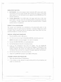
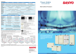
Mlr
IRF GAIN
CONTROL
DIGITAL
I
CHANNEL INDICATOR
CLARIFIER
.
I
RF POWER/"S"
LED
CH9 INDICATOR
I
METER
TWO COLOR
INDICATOR
I
,
uniden
AM-St;B
VOLUME/SQUELCH
CONTROL
I
I
TRAI\ISCEIVI!R
NB/ANL
SWITCH
3-MODE INDICATOR
PA CAPABILITY
I
MODE SELECTOR
I
PRESIDENT
AX 144
I
CHANNE~ SELECTOR SWITCH
CH9/0FF SWITCH
DIMMER CONTROL
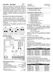
OPERATING CONTROLS
Your AX 144, designed for ease of operation,
operating controls:
is provided with the following
1. OFF/ON VOLUME: To turn the transceiver on, rotate the control clockwise
past click. To turn the transceiver off, rotate the control counterclockwise past
click. Rotate the control clockwise for a comfortable audio volume level.
2. CHANNEL SELECTOR: This switch is used to select anyone
of the 40
Citizens Band channels. Channel 9 has been reserved by the D.O.C. for
emergency communications involving the immediate safety of life of individuals
or immediate protection of property. Channel 9 may also be used to render
assistance to a motorist.
3. MODE SELECTOR: This switch selects AM, USB or LSB mode of operation.
This selector changes the mode of operation of both transmitter and receiver
simultaneously.
Set the selector to the mode on which you wish to communicate. For easier
identification of the mode, LED mode indicator is provided in three different
colors, green for AM, yellow for USB, and red for LSB.
-9-
-
-
-
-------~
~
,~
T
4. SQUELCH: The squelch control is normally set to a position which just
eliminates undesired background noise with no signal present. With the audio
volume adjusted to a satisfactory level, rotate the Squelch control clockwise to
the point where the sound from the speaker is cut off. In this position, there will
be no sound from the speaker until a signal is received. In order to hear weak
signals, it may be necessary to rotate the Squelch control counterclockwise,
allowing some background noise to be heard.
5. CLARI FI ER: The clarifier is normally set to the center position. This feature
has several uses and can greatly enhance receiver operation. If a receive signal
is slightly off frequency, this control can be operated to optimize the receive
signal. This control is primarily intended to tune in SSB signals, but, it may be
also used to optimize the AM signal.
6. MIKE GAIN: This control is used to adjust, as required, microphone input
sensitivity for optimum amount of modulation in transmit UN IDEN's citizen's
band transceivers have been designed to permit the user to attain levels of
modulation up to 100% depending on the setting of the microphone gain
control, using the microphone provided with the unit. UNIDEN's automatic
compression and peak limiting circuits assure maximum modualtion with minimum distortion.
7. DIMMER SWITCH: This switch is used to adjust the brightness of the LED
channel display and the meter. 0 IM position reduces brightness.
8. CH9 SWITCH: This switch is for use when emergency communication is needed
on the emergency channel CH9. Pressing the CH9 switch activates CH9
regardless of the position of the channel selector switch. When CH9 switch is
pressed, the channel display is blanked and the CH9 indicator is activated.
9. PA-CB SWITCH: This control engages the PA function. The PA function should
not be used unless an external speaker is connected. In the CB position, the PA
function is disabled and the radio will transmit and receive on the selected
channel.
10. NB/ANL SWITCH: When the switch is placed in the NB/ANL position, both of
RF Noise Blanker and Automatic Noise Limiter circuits are activated. The
NB is very effective for repetitive impulse noise such as ignition noise. The
ANL reduces annoying hash-type noises.
11. RF GAIN: This control is used primarily to optimize reception in strong signal
areas. Gain is reduced by counterclockwise rotation of the control.
.. r\
- 10-
-
1
+
<:::::::e: -
-
INDICATOR FUNCTION
1.
S/RF METER: This meter displays relative transmitter RF output power when
transmitting, and input signal strength when receiving. The meter is illuminated
when power is on, the illumination can be adjusted by the DIMMER switch for
optimum brightness.
2.
TX/RX INDICATOR: The TX/RX light in the upper right corner of the front
panel lights in red color when the microphone button is pressed and transmitter
is in operation. It lights in green color when the microphone button is released
and the receiver is in operation.
PRESSTO TALK MICROPHONE
The receiver and transmitter are controlled by the press-to-talk switch on the
microphone. Press the switch and the transmitter is activated. Release the switch
to receive. When transmitting, hold the microphone about three inches from your
mouth and speak at a normal voice level.
RECEIVE OPERATING PROCEDURE
1.
Place the CB-PA switch in CB position.
2. Turn the set on by turning the VOLUME CONTROL clockwis~, past click.
NOTE: Microphone must be plugged in for receiver to operate.
3.
Set the VOLUME CONTROL to a comfortable level.
4.
Set the Mode Selector Switch to the desired mode.
5.
Listen to the background noise from the speaker. Turn the SQUELCH
CONTROL slowly clockwi-se, until the noise just disappears. The Squelch is now
properly adjusted. The receiver will remain quiet until a signal is received. Do
not advance th€ control too far, or some of the weaker signals will not be heard.
6.
Set the Channel Selector to the desired channel.
7.
Adjust the CLARIFIER to clearly receive SSB or AM signals.
TRANSMIT OPERATING PROCEDURE
1.
Select the desired channel of transmission.
2.
If the channel is clear, depress the push-to-talk switch on the microphone and
speak in a normal voice.
- 11 -
'f"::;
-
I
j
-------
,
WARNING
Oper:ation of this equipment requires a valid station license issued by the Department of Communication Do not transmit with your equipment until you have
a license.
- 12-
1
rt
---
<::::;
MAINTENANCE
n
.-
-~
AND ADJUSTMENT
This transceiver is especially designed for the environment encountered in mobile
installations. The use of all solid state circuitry and its light weight result in high
reliability. Should failure occur, however, replace parts only with identical parts. Do
not substitute.
-13 F::
-
------~
- 14-
-
I
-----
1
,
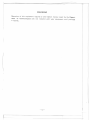
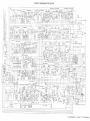
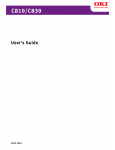
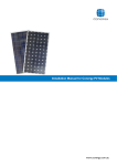
CIRCUIT DIAGJAM
FOR AX144
r-----------------------------------------------I PC-833
.~
V!
n;
!~
I
I
I
I
I
I
I
J
I
I
I
I
I
I
I
I
I
I
I
I
I
I
I
I
I
I
TRI 2SCI675L
.'0'
,I
PI-ooe
I
I
I
I
I
I
I
I
0404-' I
.O/ANC I
I
I
I
I
I
I
I
I
I
I
I
J
~
I
I
I
I
I
I
I
I
I
I
I
I
I
I
I
I
I
I
I
I
I
I
UTUAO7524T A
Printed
in The Philippines
x:
uniden@
12 MONTHS FULL WARRANTY
WARRANTOR:
UNIDEN AUSTRALIA
N.S.W. 2216 ("UNIDEN").
ELEMENTS
OF WARRANTY.
PTY. LTD. 345 Princes Highway,
Uniden Australia warrants,
for the duration
Rockdale,
of this war-
ranty, its UNIDEN CB Product to be free from defects in materials and craftsmanship
with only the limitation or exclusions set out below.
WARRANTY DURATION. This warranty shall terminate and be of no further effect
One (1) year after the date of original purchase of the Product or at the time the Product is (a) damaged or not maintained as reasonable and necessary, (b) modified, (c)
improperly installed, (d) is repaired by someone other Warrantor for a defect or malfunction covered by this Warranty, or (e) used in a manner or- purpose for which the
Product was not intended.
PARTS COVERED.
STATEMENT
This Warranty
covers all components
of the Products.
OF REMEDY. 'n the event that the Product does not conform
to this
Warranty at any time while this Warranty is effective, Warrantor will repair the defect
and return it to you prepaid, without charge for parts, service, or any other costs incurred by Warrantor or its representatives
in connection with the performance of this
Warranty. In addition, if the Product contains a defect or malfunction which is not repairad after a reasonable number of attempts by Warrantor to repair the Product, the
Product or defective component
will at our discretion, will be replaced without
charge, when the defective product is delivered to the warrantor at 345 Princes Highway, Rockdale, N.S.W. 2216 free and clear of all liens and encumbrances.
Please note
that while the Product will be remedied under this Warranty without charge. THIS
WARRANTY DOES NOT COVER OR PROVIDE FOR THE REIMBURSEMENT OR PAYMENT OF INCIDENTAL OR CONSEQUENTIAL DAMAGES.
Some states do not allow this exclusion or limitation of incidental or consequential
mages, so the above limitation or exclusion may not apply to you.
da-
PROCEDUREFOROBTAINING PERFORMANCEOF WARRANTY: In the event that
the Product does not conform to this Warranty, the Product should be shipped prepaid, to Warrantor at 345 Princes Highway, Rockdale, N.S.W. 2216. THE ORIGINAL
ORCOpy OFTHESALESRECEIPTOROTHERVALID EVIDENCEOFTHEDATEOFTHE
ORIGINALPURCHASEMUST ACCOMPANYTHIS PRODUCT.
LEGAL REMEDIES: This Warranty gives you specific legal rights, and you may also
have other rights which vary from state to state
uniden~
Australia Pty. Ltd.
l
HEAD OFFICE:
345 Princes Highway, Rockdale, N.S.W. 2216
Phone: 599 3355
Fax: (02) 599 7657
.f
BRISBANE
3/12 Randall Street, Slacks Creek,
Old. 4127
Phone (07) 290-1188
Fax (07) 8084251
PERTH
23 Geddes Street, Balcatta,
W.A. 6021
MELBOURNE & TASMANIA
446-448 Bell Street, East Preston,
VIC. 3072
Phone (03) 484-0373
Fax (03) 4846057
ADELAIDE
Phone (09) 344-3937
Fax (09) 349 8165
72-74 Halifax Street, Adelaide
S.A. 5000
Phone (08) 223-4235
Fax (08) 223 1471
UTUAO1524TC
Printed in the Philippines
@ Copyright 1992 Uniden Corporation
~
--
~