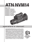
1
PVS-14/6015
Night Vision Monocular
Operation and
Maintenance Manual
Shop for Armasight products online at:
Important Export Restrictions! Commodities, products, technologies and services of this manual are controlled by the U.S.
Department of State Office of Defense Trade Controls, in accordance with International Traffic in Arms (ITAR), Title 22, Code of
Federal Regulations Part 120-130 and/or by the Export Administration Regulations (EAR) of U.S. Department of Commerce. At any
time when a license or a written approval of the U.S. Government
is applicable to it, it is illegal and strictly forbidden to export, intend to export, transfer in any other manner whatsoever, sell any
hardware or technical data, provide any associated service to any
non-U.S. resident, beyond or within the United States territory,
until the valid license or written approval has been issued by the
Departments of the U.S. Government having jurisdiction. Additionally U.S. law prohibits the sale, transfer, or export of items to
certain restricted parties, destinations, and embargoed countries,
as identified on lists maintained by the U.S. Department of State,
the U.S. Department of Commerce, and the U.S. Department of
Treasury. It is the responsibility of the Customer to be aware of
these lists. The sale, transfer, transportation, or shipment outside of the U.S. of any product prohibited or restricted for export
without complying with U.S. export control laws and regulations,
including proper export licensing, documentation or authorization, is unlawful and may result in civil and/or criminal penalties
and/or constitute a federal crime. Diversion contrary to U.S. law
is strictly prohibited.
www.SCOUTBASECAMP .ca 1.877.766.5412
SAFETY SUMMARY
Before operating this product, carefully read and study this Operation and Maintenance Manual.
The PVS-14/6015 is a precision electro-optical instrument, and requires careful handling. To avoid damage to the equipment or physical harm to the user when operating the PVS-14/6015, follow all WARNINGS, CAUTIONS and NOTES.
Below you will find definitions of the following alerts that appear throughout this Manual:
WARNING — Identifies a clear danger to the person operating the equipment.
CAUTION – Identifies risk of damage to the equipment.
NOTE – Serves to highlight essential procedures, conditions, and statements, or convey important instructional data to the user.
WARNING:
This product contains natural rubber latex which may cause allergic reactions! The FDA
has reported an increase in the number of deaths that are associated with an apparent sensitivity to natural latex proteins. If you are allergic to latex, it is a good idea to learn which products
contain it and strictly avoid exposure to those products.
WARNINGS:
Toxic Material
The image intensifier’s phosphor screen contains toxic materials.
• If the image intensifier breaks, be extremely careful to avoid inhaling the phosphor screen
material. Do not allow the material to come in contact with the mouth or open wounds on the
skin.
• If the phosphor screen material comes in contact with your skin, wash it off immediately with
soap and water.
• If you inhale/ swallow any phosphor screen material, drink a lot of water, induce vomiting, and
seek medical attention as soon as possible.
WARNINGS:
• The monocular will not turn off automatically when flipped up. The monocular needs to be
turned off with the power switch.
• The compass illuminator is visible to other people using night vision devices.
• Do not use contaminated eyecups or eyeguards. If contaminated, they must be replaced.
• When installing the headmount over the protective mask, be careful not to break the protective mask’s seal around your face.
The information provided in this manual is for familiarization purposes only; the contents may undergo further
changes with no commitment by Armasight© to notify customers of any updates.
Armasight© assumes no responsibility for any misprints or other errors that this manual may contain.
©2012 by Armasight. All rights reserved.
Shop for Armasight products online at:
2
www.SCOUTBASECAMP .ca 1.877.766.5412
CAUTION:
• The PVS-14/6015 is a precision optical instrument and must be handled carefully at all times
to prevent damage.
• To prevent damage, be especially careful when leaving the helmet mount in the flipped up
position or removing the helmet mount from the helmet.
• Do not scratch the external lens surfaces or touch them with your fingers.
• Do not wipe the demisting shield with lens paper while it is damp, or using wet lens paper, as
this can damage the coating.
• To protect the image intensifier, keep the lens cap securely fitted over the objective lens when
the monocular is not in use or when it is being operated in daylight conditions.
• Light from the IR illuminator is invisible to the unaided eye. However, it can be detected by
other night vision devices.
• If you use the rubber eyecups for a long period of time, you may suffer skin inflammation. If
you develop any symptoms, consult a doctor immediately.
NOTES:
To avoid physical injury and damage to the equipment, carefully read and understand the following safety precautions.
• The equipment requires some ambient light (moonlight, starlight, etc.) to operate.
• Performance of the device in nighttime conditions depends on the level of ambient light in
the environment. Please remember the following:
— The level of ambient light is reduced by the presence of clouds, shade, or objects that block
natural light (trees, buildings, etc.).
— The equipment is less effective when operated in shadows and other darkened areas.
— The equipment is less effective when operated in rain, fog, sleet, snow, dust or smoke.
— The equipment will not “see” through dense smoke.
• At operating temperatures below -20°C (-4°F), the use of an alkaline battery is not recommended, as the battery life will be severely reduced. Under said conditions, lithium-iron disulfide 1.5V AA batteries or their equivalent should be used.
• The IR illuminator is intended for increased illumination, as needed, when viewing at a close
distance of up to 3m.
• For the purpose of returning defective components, retain all packaging materials.
Shop for Armasight products online at:
www.SCOUTBASECAMP .ca 1.877.766.5412
3
LIST OF CONTENTS
TITLE
PAGE
Safety Summary
List of Contents
List of Figures
How to Use This Manual
1. INTRODUCTION
1.1 General Information
1.1.1 Type of Manual
1.1.2 Model Number and Equipment Name
1.1.3 Purpose of Equipment
1.1.4 Reporting Equipment Improvement Recommendations
1.2 Warranty Information and Registration
1.2.1 Warranty Information
1.2.2 Limitation of Liability
1.2.3 Product Warranty Registration
1.2.4 Obtaining Warranty Service
1.3 Cross References
1.4 List of Abbreviations
1.5 Glossary
2. DESCRIPTION AND DATA
2.2 Equipment Description
2.2.1 Equipment Characteristics, Capabilities, and Features
2.2.2 Location and Description of Major Components
2.2.3 Equipment Data
2.3 Principles of Operation
2.3.1 Mechanical Functions
2.3.2 Optical Functions
2.3.3 Electronic Circuit Function
3. OPERATING INSTRUCTIONS
3.1 Description and Use of Operator’s controls and indicators
3.1.1 Operator Controls and Indicators
3.2 Preventive Maintenance Checks and Service s (PMCS)
3.2.1 Preventive Maintenance Checks and Services
3.2.2 Resolution Check Using the TS-4348/UV Test Set
3.2.3 Inspection Criteria for Proper Image Intensifier Operation
3.3 Assembly and Preparation for Use
3.3.1 Unpacking
3.3.2 Installation of the Battery
3.3.3 Installation of the Eyecup Or Eyeguard
3.3.4 Installation of the Demist Shield
3.3.5 Installation of the Sacrificial Window
3.3.6 Installation and Adjustment of the Headmount
3.3.7 Installation of the Headmount/Helmet Mount Adapter
3.3.8 Installation of the Helmet Mount to a Helmet
3.3.9 Installation of the Headmount with a Protective Mask
Shop for Armasight products online at:
4
2
4
5
6
7
7
7
7
7
7
8
8
8
8
9
9
10
11
12
12
12
12
15
16
16
16
17
18
18
18
20
20
24
26
29
29
29
30
30
31
31
32
32
33
www.SCOUTBASECAMP .ca 1.877.766.5412
3.3.10 Installation of the Weapon Mount
3.3.11 Installation of the Compass Caution
3.3.12 Installation of the 3x Magnifier
3.3.13 Mounting MUNVM to a Weapon with a Quick-Release Picatinny Mount Adapter
3.3.14 Mounting a MUNVM to a Weapon with the AIM Advanced Integrated Mount
3.4 Operating Procedures
3.4.1 Hand-Held Operation
3.4.2 Head-Mounted Operation
3.4.3 Helmet-Mounted Operation
3.4.4 Weapon-Mounted Operation
3.4.5 IR Source Operations
3.4.6 Operation with a Compass
3.4.7 Operation with a 3x Magnifier
3.4.8 Operation with a Gain Control
3.4.9 Preparation for Storage
3.5 Operation under Unusual Condition
3.5.1 Operation in Dusty or Sandy Areas
3.5.2 Operation in Rainy or Humid Conditions
3.5.3 Operation in Salt Water Areas
3.5.4 Operation in Nuclear, Biological and Chemical (NBC) Environments
4. MAINTENANCE PROCEDURES AND TROUBLESHOOTING
4.1 Lubrication Instructions
4.2 Troubleshooting Procedures
4.2.1. Troubleshooting
4.3. Operator’s Maintenance Procedures
4.3.1 Cleaning the MUNVM
4.3.2 Headmount Maintenance
4.3.3 Neck Cord Maintenance
4.4 Service/Packing and Unpacking
4.4.1 Return Instructions
APPENDIX
A. Components of End Item (COEI) and Basic Issue Items (BII) Lists
B. Additional Authorization List (AAL)
C. Expendable and Durable Items List
D. Product Warranty Registration Card
Alphabetical Index
34
35
36
36
37
38
38
38
39
41
42
42
43
43
44
44
44
45
45
45
46
46
46
45
47
47
48
49
49
49
50
50
52
53
54
55
LIST OF FigureS
FIGURE TITLE
PAGE
2-1. Components of NVMPS 2-2. 3X Magnifier and Compass for PVS-14/6015 2-3. Shipping and storage cases for PVS-14/6015 2-4. Multi-Use Night Vision Monocular 2-5. Optional Equipment 2-6. Optical Function Diagram Shop for Armasight products online at:
13
13
14
14
14
17
www.SCOUTBASECAMP .ca 1.877.766.5412
5
3-1. Monocular Controls and Indicators 3-2. TS-4348/ UV Test Set Pattern 3-3. Shading 3-4. Edge Glow 3-5. Bright Spots and Emission Points 3-6. Fixed-Pattern Noise 3-7. Chicken Wire 3-8. Battery, Eyecup and Eyeguard Installation 3-9. MUNVM Headmount Adjustments 3-10. Headmount/Helmet Mount Adapter Installation 3-11. Installation of Helmet Mount 3-12. Helmet Mount 3-13. Reassembly of Helmet Mount 3-14. Weapon Mount Usage 3-15. Locating the Magnet 3-16. Compass Installation 3-17. 3X Magnifier Installation 3-18. 3X Magnifier Installation with Focus Ring Adapter 3-19. Mounting Optional Bracket to the MUNVM
3-20. Clamping Device on the Mount Top
3-21. QRM Assembled with MUNVM
3-22. AIM Assembled with MUNVM
3-23. Headmount/Helmet Mount Adapter Operation 3-24. Tilt and Flip-up Assembly Mechanisms 3-25. View Through Installed Compass 3-26. Gain Control 4-1. Reinstalling the Neck Pad 4-2. Threading the Sliding Bar Buckles A-1. Components of End Item 18
25
26
27
27
28
29
30
31
32
33
33
33
34
35
35
36
36
37
37
37
37
39
40
43
43
48
48
51
HOW TO USE THIS MANUAL
USAGE
You must familiarize yourself with the entire manual before operating the equipment. Before performing any kind of maintenance on your device, read the section on maintenance in its entirety. Follow all
WARNINGS, CAUTIONS, and NOTES.
MANUAL OVERVIEW
This manual contains sections on Operating and Maintaining the PVS-14/6015 Night Vision Monocular.
The Components of End Items (COEI) and Basic Issue Items (BII) Lists can be found in Appendix A.
The Additional Authorization List (AAL) can be found in Appendix B.
The Expendable and Durable Items List can be found in Appendix C.
Shop
forProduct
Armasight
products
online at: Card
www.
.ca 1.877.766.5412
The
Warranty
Registration
can be found in Appendix D.
SCOUTBASECAMP
6
1
INTRODUCTION
1.1 GENERAL INFORMATION
1.1.1 TYPE OF MANUAL
Operation and Maintenance.
1.1.2 Model Number and Equipment Name
PVS-14 Multi-Use Night Vision Monocular.
6015 Multi-Use Night Vision Monocular.
1.1.3 PURPOSE of Equipment
To provide the operator with the ability to observe at night under moonlight and starlight conditions.
The PVS-14/6015 can be used as a handheld, head-mounted, helmet-mounted or weapon-mounted
device to allow walking, weapon firing, short-range surveillance, map reading, vehicle maintenance,
and administration of first aid.
1.1.4 Reporting Equipment Improvement Recommendations
User recommendations for improvements to the device are encouraged.
Mail your comments to Armasight Inc., 815 Dubuque Avenue, South San Francisco, CA 94080, USA.
Or, send an email to [email protected].
Shop for Armasight products online at:
www.SCOUTBASECAMP .ca 1.877.766.5412
7
1.2warranty INFORMATION and Registration
1.2.1 WARRANTY INFORMATION
This product is guaranteed to be free from manufacturing defects in material and workmanship under
normal use for a period of two (2) years from the date of purchase. In the event that a defect covered
by the below warranty occurs during the applicable period stated above, Armasight, at its discretion,
will either repair or replace the product; such action on the part of Armasight shall be the full extent of
Armasight’s liability, and the Customer’s sole and exclusive reparation. This warranty does not cover a
product if it has (a) been used in ways other than its normal and customary manner; (b) subjected to
misuse; (c) subjected to alterations, modifications or repairs by the Customer of by any party other than
Armasight without prior written consent of Armasight; (d) special order or “close-out” merchandise
or merchandise sold “as-is” by either Armasight or the Armasight dealer; or (e) merchandise that has
been discontinued by the manufacturer and either parts or replacement units are not available due to
reasons beyond the control of Armasight. Armasight shall not be responsible for any defects or damage that in Armasight’s view are a result from the mishandling, abuse, misuse, improper storage or
improper operation of the device, including use in conjunction with equipment that is electrically or
mechanically incompatible with, or of inferior quality to, the product, as well as failure to maintain the
environmental conditions specified by the manufacturer. CUSTOMER IS HEREBY NOTIFIED THAT OPERATION OF THE EQUIPMENT DURING DAYLIGHT HOURS OR UNDER ANY EXCESSIVE LIGHT CONDITIONS
MAY PERMANENTLY DAMAGE THE INTERNAL COMPONENTS OF THE UNIT AND SAID DAMAGE WILL
NOT BE COVERED UNDER THIS WARRANTY. This warranty is extended only to the original purchaser.
Any breach of this warranty shall be enforced unless the Customer notifies Armasight at the address
noted below within the applicable warranty period.
The Customer understands and agrees that except for the foregoing warranty, no other warranties
written or oral, statutory, expressed or implied, including any implied warranty of merchantability or
fitness for a particular purpose, shall apply to the product. All such implied warranties are hereby and
expressly disclaimed.
1.2.2 Limitation of Liability
Armasight will not be liable for any claims, actions, suits, proceedings, costs, expenses, damages or
liabilities arising out of the use of this product. Operation and use of the product are the sole responsibility of the Customer. Armasight’s sole undertaking is limited to providing the products and services
outlined herein in accordance with the terms and conditions of this Agreement. The provision of products sold and services performed by Armasight to the Customer shall not be interpreted, construed,
or regarded, either expressly or implied, as being for the benefit of or creating any obligation toward
any third party of legal entity outside Armasight and the Customer; Armasight’s obligations under this
Agreement extend solely to the Customer. Armasight’s liability hereunder for damages, regardless of
the form or action, shall not exceed the fees or other charges paid to Armasight by the Customer or
Customer’s dealer. Armasight shall not, in any event, be liable for special, indirect, incidental, or consequential damages, including, but not limited to, lost income, lost revenue, or lost profit, whether such
damages were foreseeable or not at the time of purchase, and whether or not such damages arise
out of a breach of warranty, a breach of agreement, negligence, strict liability or any other theory of
liability.
1.2.3 Product Warranty Registration
In order to validate the warranty on your product, Armasight must receive a completed Product Warranty Registration Card for each unit, or the Customer can complete a warranty registration on our
website, at www.armasight.com. Please complete the included form (Appendix D) and immediately
mail it to our Service Center:
Armasight Inc.
815 Dubuque Avenue
South San Francisco
CA 94080
United States of America.
Shop for Armasight products online at:
8
www.SCOUTBASECAMP .ca 1.877.766.5412
1.2.4 Obtaining Warranty Service
To obtain warranty service on your unit, the End-user (Customer) must notify the Armasight service
department via email. Send any requests to [email protected] to receive a Return Merchandise
Authorization number (RMA). When returning any device, please take in the product to your retailer, or
send the product, postage paid and with a copy of your sales receipt, to Armasight Corporation’s service center at the address listed above. All merchandise must be fully insured with the correct postage;
Armasight will not be responsible for improper postage or merchandise that becomes lost or damaged
during shipment. When sending product back, please clearly write the RMA# on the outside of the
shipping box. Please include a letter that indicates your RMA#, the Customer’s Name, a Return Address,
reason for the return, Contact information (valid telephone numbers and/or an e-mail address), and
proof of purchase that will help us to establish the valid start date of the warranty. Product merchandise returns that do not have an RMA# listed may be refused, or a significant delay in processing may
occur. Estimated Warranty service time is 10-20 business days. The End-user/ Customer is responsible
for postage to Armasight for warranty service. Armasight will cover return postage/ shipping after warranty repair to the End-user/ Customer only if the product is covered by the aforementioned warranty.
Armasight will return the product after warranty service by domestic UPS Ground service and/ or domestic mail. Should any other requested, required or international shipping methods be necessary, the
postage/ shipping fee will be the responsibility of the End-user/ Customer.
1.3 Cross References
Common Name Official Name
Allen Wrench
Socket Head Screw Key
Battery Compartment
Battery Box Cover
Shipping Case
Textile Bag
Cotton Swab
Disposable Applicator
Neoprene Jack Plug
Plug Assembly
O-Ring
Gasket
Safety Screw
Electrical Dial-Knob Lock
Pattern Generator
Optical Instrument Reticle
Lens Covers
Exit Port Covers
Paddle Switch
Remote Cable Switch
Batteries
AA
Technical Manual
Operator and Field Maintenance Manual
Tape Fastener Loop
Fastener, Loop Tape
Tape Fastener Hook
Fastener, Hook Tape
Shop for Armasight products online at:
www.SCOUTBASECAMP .ca 1.877.766.5412
9
1.4 List of Abbreviations
AAL
BII
CAGEC
cm
COEI
CPC
CTA
DA
EIC
EIR
FM
Hrs
IR
JTA
lbs
LED
MUNVM
NVMPS
MTOE
N/A
NBC
NSN
Pam
PASGT
PMCS
Qty
Recm
Rqr
SF
TDA
TM
TOE
U/M
Vdc
Additional Authorization List
Basic Issue Items
Commercial and Government Entity Code
Centimeters
Components of End Item
Corrosion Prevention and ControlCommon Table of AllowancesDepartment of the Army
End Item Code
Equipment Improvement Recommendation
Field Manual
Hours
Infrared
Joint Table of Allowances
Pounds
Light Emitting Diode
Multi-Use Night Vision Monocular
Night Vision Multi-Purpose System
Modified Table of Organization and EquipmentNot Applicable
Nuclear, Biological, and Chemical
National Stock Number
Pamphlet
Personal Armor System Ground Troops
Preventive Maintenance Checks and Services
Quantity
Recommended
Required
Standard Form
Table of Distribution and AllowancesTechnical Manual
Table of Organization and EquipmentUnit of Measure
Volts, direct current
Shop for Armasight products online at:
10
www.SCOUTBASECAMP .ca 1.877.766.5412
1.5 GLOSSARY
BLACK SPOTS. Cosmetic blemishes in the image intensifier of the MUNVM, or dirt or debris between
the lenses.
BRIGHT SPOTS. Defects that can appear in the image area of the MUNVM. This condition is caused by
a flaw in the film on the microchannel plate. A bright spot is a small, non-uniform, bright area that may
flicker or appear constant. Bright spots are cosmetic blemishes that are signal-induced, and usually
disappear when all light is blocked out.
BROWPADS. Three hook-and-pile browpads are provided to adjust the headmount to fit different
head sizes. The thin browpad (for larger heads) comes attached to the headmount and the thick, or
medium (for smaller heads) browpads are stored in the carrying case.
CHICKEN WIRE. An irregular pattern of dark thin lines in the field-of-view either throughout the image
area or in parts of the image area. In the worst cases of Chicken Wire, these lines will form hexagonal or
square, wave-shaped lines.
DARK (OR DARK AREA). A place in which there is very little light. It does not mean total darkness.
Generally, this means conditions similar to a quarter-moon or starlit night.
DARK-ADAPTED. When the user’s eyes have adjusted to the monocular’s output under low light conditions.
DIOPTER. A unit of measure used to define eye correction. Adjustments to the diopter adjustment will
provide a clearer image for each eye.
EDGE GLOW. A defect in the image area of the monocular. Edge glow is a bright area (sometimes sparkling) in the outer portion of the viewing area.
EMISSION POINT. A steady or fluctuating pinpoint of bright light in the image area and does not go
away when all light is blocked from the objective lens of the monocular. The position of an emission
point within the image area of the monocular does not move. An emission point should not be confused with a point light source in the distance.
FIXED-PATTERN NOISE. A cosmetic blemish in the image area characterized by a faint, hexagonal
(honeycomb) pattern throughout the viewing area. It most often occurs in excessive light conditions or
when viewing very bright lights. Fixed-pattern noise is inherent in the structure of the fiber optics and
can be seen in every image intensifier if the level of light is high enough.
FLASHING. A defect in the image area of the monocular. The image appears to flicker or flash.
FLICKERING. See “flashing.”
GAIN. The number of times a night vision device amplifies light input.
IMAGE INTENSIFIER. An electro-optical device that detects and amplifies ambient light to produce a
visual image.
INFINITY FOCUS. Adjustment of the objective lens so that a distant object, such as a star or the point
light on a distant tower, forms the sharpest image.
INTERMITTENT OPERATION. A defect in the image area of the monocular. See “flashing.”
IR SOURCE. IR Light Emitting Diode (LED). When turned on, the IR source provides additional illumination to enhance existing light conditions, and should be used only for performing nearby tasks.
MICROCHANNEL PLATE. A current-multiplying optical disk that intensifies the electron image produced by the photocathode.
PHOTOCATHODE. The input optic of an image intensifier that absorbs light energy and releases electrical energy in the form of an electron image.
SCINTILLATION. A faint, random, sparkling effect throughout the image area. Scintillation is a normal
characteristic of the image intensifier and should not be confused with emission points. Scintillation is
more pronounced under low light conditions. Also called “video noise.”
SHADING. The viewed image should be a full circle. If shading is present, you will not see a fully circular
image. Shading is indicative of a dying photocathode and is caused by a defective vacuum seal of the
image intensifier. Shading is very dark and you cannot see an image through it.
Shop for Armasight products online at:
www.SCOUTBASECAMP .ca 1.877.766.5412
11
2
DESCRIPTION AND DATA
2.1 EQUIPMENT description
2.2.1. EQUIPMENT CHARACTERISTICS, CAPABILITIES, AND FEATURES
The PVS-14/6015 is a hand-held, head-mounted, helmet mounted, or weapon-mounted night vision
system that enables walking, weapon firing, short-range surveillance, map reading, vehicle maintenance, and administration of first aid in both moonlight and starlight conditions. Each unit allows for
vertical adjustment (by using the head strap), fore-and-aft adjustment, objective lens focus and eyepiece focus. The monocular is also equipped with an IR source and a low battery indicator. The PVS-14
model is equipped with a manual gain control.
2.2.2. LOCATION AND DESCRIPTION OF MAJOR COMPONENTS
The NVMPS includes the items shown in Figures 1-1, 1-2, 1-3. The major components are the headmount, helmet mount, monocular, carrying case, and the shipping and storage case.
a. Monocular
The monocular (see Figure 2-4) consists of various components such as an objective lens, an image
intensifier (not shown), an eyepiece lens and a battery cap.
The monocular also uses the accessories listed below:
Demist Shield – The demist shield (Figure 2-1) is used to prevent the eyepiece lenses from becoming fogged.
Sacrificial Window – A replaceable sacrificial window (Figure 2-1) is supplied to protect the objective lens during operation in adverse conditions.
Compass – The compass (Figure 2-2) enables the operator to see azimuth readings in the monocular.
Tethering Cord – The tethering cord (Figure 2-1) enables the user to attach the compass or 3X magnifier to a button hole or belt loop to guard against dropping or losing these items.
3X Magnifier – (Additional Authorized Item) The 3Xmagnifier (Figure 2-2) is a lens assembly which
can be added to the monocular to extend the operator’s observation ranges.
b. Headmount
The headmount (Figure 2-1) secures the monocular to the operator’s head for night viewing and provides freehand support for use with a weapon, protective mask, or for other purposes in which freehand operation is required. It is adjustable and cushioned. The thin browpad should be used for larger
heads, and comes attached to the headmount; the thick and medium browpads should be used for
smaller heads, and are stored in the carrying case.
Shop for Armasight products online at:
12
www.SCOUTBASECAMP .ca 1.877.766.5412
HEAD/HELMET MOUNT
ADAPTER
WEAPON MOUNT
TETHERING
CORD
HEADMOUNT
THIN BROWPAD
HELMET MOUNT
BATTERY CARTRIDGE
MEDIUM AND
THICK BROWPADS
CARRYING CASE
OPERATOR’S
MANUAL
LENS PAPER
NECK CORD
DEMIST
SHIELD
SACRIFICIAL
WINDOW
BATTERy
EYEGUARD
OBJECTIVE
LENS CAP
CARRYING CASE
STRAP
MONOCULAR
Figure 2-1. Components of NVMPS
COMPASS
3X MAGNIFIER
(ADDITIONAL ITEM)
Figure 2-2. 3X Magnifier and Compass for PVS-14/6015
Shop for Armasight products online at:
www.SCOUTBASECAMP .ca 1.877.766.5412
13
(see Figure 2-1. for details)
SHIPPING
AND
STORAGE
CASE
Figure 2-3. Shipping and storage cases for PVS-14/6015
EYEPIECE
LENS
OBJECTIVE
LENS
POWER
SWITCH
BATTERY
CAp
GAIN
CONTROL
Figure 2-4. Multi-Use Night Vision Monocular
Bracket
AIM
AIM PVS14 Kit
(ANKI000046)
Double Lever-Lock Quick Release
Picatinny Mount Adapter #26
(ANAM000004)
Bracket PVS14 #62
(ANKI000046)
Figure 2-5. Optional Equipment
Shop for Armasight products online at:
14
www.SCOUTBASECAMP .ca 1.877.766.5412
c. Helmet Mount
The helmet mount (Figure 2-1) secures the monocular to the Personal Armor System Ground Troops
(PASGT) helmet, allowing freehand support for use with a weapon, protective mask and/ or other purposes in which freehand operation is required. The new helmet mount is made of a ruggedized metal,
unlike the older version, which is made of plastic.
d. Headmount/Helmet Mount Adapter
The headmount/ helmet mount adapter (Figure 2-1) is attached to the monocular to allow use with the
headmount or helmet mount. It allows mounting in front of the left or right eye.
e. Weapon Mount
The weapon mount (Figure 2-1) adapts the monocular to the receiver rail as configured for the modular
weapon system kit.
f. Carrying Case
The carrying case (Figure 2-3) is provided for transportation and protection of the monocular, headmount, battery and accessories. Two slide keepers are provided for belt attachment; three D-rings are
provided for shoulder and leg strap attachment. A carrying case strap is also provided, and can be attached to the two D-rings on the back of the carrying case.
g. Shipping and Storage Case
The NVMPS is supplied in a shipping and storage case (Figure 2-3).
h. AIM PVS14 Kit
AIM Advanced Integrated Mount (Figure 2-5) allows the user to quickly convert the PVS-14 into a weapon sight. The Kit includes the AIM and bracket for installing PVS-14 onto the AIM.
i. Double Lever-Lock Quick Release Picatinny Mount Adapter #26
Small arms adapter that allows the PVS-14 to be mounted on a weapon using Picatinny Mil 1913 rail
(Figure 2-5).
j. Bracket PVS14 #62
Allows the PVS-14 to be mounted on the Quick Release Picatinny Mount Adapter (Figure 2-5).
2.2.3. EQUIPMENT DATA
The following tables provide information pertaining to the operational, electrical, mechanical, optical,
and environmental characteristics of the monocular.
Table 2-1. OPERATOR ADJUSTMENT LIMITS
ITEM
LIMITS
Diopter Focus
+2 to -6 diopters
Objective Focus
25cm (9.8”) to infinity
Table 2-2. Electrical Data
ITEM
DATA
Power Source
Battery (1.5 Vdc max ea.)
Battery Requirements
1 AA Alkaline or 1 AA 1.5 Vdc Lithium L91
Shop for Armasight products online at:
www.SCOUTBASECAMP .ca 1.877.766.5412
15
Table 2-3. MECHANICAL DATA
ITEM
CHARACTERISTICS
Shipping and Storage Case
Size: Approx. 356 x 241 x 203 mm (14” x 9.5” x 8”)
Weight: 1.09kg (2.4 lbs.)
Carrying Case
Size: Approx. 352 x 240 x 200 mm (14” x 9.5” x 8”)
Monocular (see Note)
Weight: 0.39kg (14 ounces)
NOTE:
The weight of the monocular does not include accessories.
Table 2-4. OPTICAL DATA
ITEM
DATA
Magnification
1.0X (3X with 3X magnifier)
Field-of-View
40° (13° with 3X magnifier)
Diopter Focus
+2 to -6 diopters
Objective Focus
25cm (9.8”) to infinity
Table 2-5. ENVIRONMENTAL DATA
ITEM
DATA
Monocular Operating Temperature
-51°C to +49°C
Monocular Storage Temperature
-51°C to +85°C
Illumination Required
Overcast starlight to moonlight
2.3principles of operation
2.3.1. MECHANICAL FUNCTIONS
The mechanical functions used to operate the NVMPS adjust to accommodate physical differences of
individual operators. These functions include the power switch, eye relief adjustment, diopter adjustment, gain control, and objective focus. The mechanical controls are identified in Figure 2-4.
NOTE:
The gain control function is not available with the 6015 or PVS-14NG model.
2.3.2 OPTICAL FUNCTIONS
The optical functions include an objective lens, image intensifier, and eyepiece lens (Figure 2-6). The
objective lens collects light reflected from the environment. The image is inverted and focused on the
image intensifier. The image intensifier converts the captured light into a visible image, re-inverting it
so that it can be viewed through the eyepiece lens.
Shop for Armasight products online at:
16
www.SCOUTBASECAMP .ca 1.877.766.5412
MICROCHANNEL
PLATE
FIBER-OPTIC
INVERTER
PHOTOCATHODE
OBJECTIVE
LENS
PHOSPHOR
SCREEN
IMAGE
INTENSIFIER
POWER
SUPPLY
EYEPIECE
LENS
EYE
Figure 2-6. Optical Function Diagram
2.3.3. ELECTRONIC CIRCUIT FUNCTION
The electronic circuit regulates the direct current voltage from the battery to the image intensifier and
IR source as required. It also monitors the output voltage of the battery and turns on a low-battery
indicator when the available battery voltage is 1.9 – 2.1 Vdc.
a. Power Source
The electronic circuit is powered by one battery.
b. High Light Cut-Off
The monocular will automatically turn off after 70 ±30 seconds of operation in daylight or other brightly lit environments. Individual bright lights (headlights, flashlights, or other concentrated light sources)
will not actuate the high light detector located on the front of the monocular. To turn the monocular
back ON, turn the power switch to RESET/ OFF, and then to ON again.
Shop for Armasight products online at:
www.SCOUTBASECAMP .ca 1.877.766.5412
17
3
OPERATING INSTRUCTIONS
3.1 Description and Use of Operator’s
Controls and Indicators
NOTE:
The MUNVM is a precision electro-optical instrument, and must be handled carefully. If the
equipment fails to operate, refer to the Troubleshooting Procedures in Chapter 4.
3.1.1. OPERATOR CONTROLS AND INDICATORS
The MUNVM is designed to adjust for different users and corrects for most differences in eyesight. The
controls and indicators for the MUNVM are shown in Figure 3-1, and are described in Table 3-1.
DIOPTER
ADJUSTMENT
LATCH
IR LENS
EYE RELIEF
ADJUSTMENT
POWER
SWITCH
OBJECTIVE
FOCUS
GAIN
CONTROL
BATTERY POLARITY
INDICATORS (HIDDEN)
HIGH LIGHT CUT-OFF WINDOW
Figure 3-1. Monocular Controls and Indicators
Shop for Armasight products online at:
18
www.SCOUTBASECAMP .ca 1.877.766.5412
NOTE:
The gain control function is not available with the 6015 model.
NOTE:
Indicators showing that the battery is low and that the IR is active are both visible in the eyepiece lens.
Table 3-1. MONOCULAR CONTROLS AND INDICATORS
CONTROLS AND INDICATORS
FUNCTIONS
Controls the monocular and IR source, ON or OFF.
Power Switch
RESET/ OFF
Same as system OFF. Also resets monocular after high light
cut-off.
ON
Monocular activated.
IR/ PULL
Turn the knob clockwise to momentarily activate the IR source.
For continuous operation of the IR, pull and turn the knob
clockwise from the ON position.
CAUTION:
Do not use excessive force when operating the power switch.
Low Battery Indicator
The low battery indicator will blink on and off when there are less than 30
minutes of battery life remaining. It is visible through the eyepiece, just outside the intensified field-of-view.
IR Source On Indicator
The IR Source On indicator will blink when the IR is activated. It is visible
through the eyepiece just outside the intensified field-of-view.
Gain Control
(PVS-14 only)
Adjusts the system gain from a minimum value of approximately 25 to a
maximum value greater than 3,000.
Objective Focus
Focuses objective lens. Adjusts for sharpest image of viewed object.
Diopter Adjustment
Focuses eyepiece lens for use without a need for glasses. Adjusts for sharpest
image of intensifier screen.
Eye Relief Adjustment
Adjusts the distance between your eye and the monocular.
Latch
Latch used for separation of monocular from head-mount/ helmet mount
adapter.
Battery Polarity Indicators
This feature, molded into the battery housing, shows the proper orientation
of the battery. Some versions have a bubble molded into the top of the battery house that indicates polarity.
Shop for Armasight products online at:
www.SCOUTBASECAMP .ca 1.877.766.5412
19
3.2 Preventive Maintenance Checks and
Services (PMCS)
3.2.1. PREVENTIVE MAINTENANCE CHECKS AND SERVICES
a. General
To verify that the MUNVM is mission-ready, perform the preventive maintenance procedures in accordance with Table 2.2 prior to each mission. Preventive maintenance procedures include inspection,
cleaning, and performance of the checkout procedures.
b. Warnings and Cautions
Always observe the WARNINGS and CAUTIONS appearing in the table. Warnings and cautions appear
before any applicable procedures. You must observe the warnings and cautions to prevent serious
injury to yourself and others, and to prevent damage to the equipment.
c. Explanation of Table Entries
(1) Item Number Column. Numbers in this column are for reference. When completing the Equipment
Inspection and Maintenance Worksheet, include the item number for the check/ service indicating a
defect. Item numbers also appear in the order in which checks and services should be performed.
(2) Interval Column. This column tells you when you must do the procedure in the Procedure Column.
BEFORE procedures must be done before you operate or use the equipment for its intended mission.
DURING procedures must be done during the time you are operating or using the equipment for its
intended mission. AFTER procedures must be done immediately after you have operated or used the
equipment.
(3) Location, Check/ Service Column. This column provides the location and the item to be checked
or serviced. The item location is underlined.
(4) Procedure Column. This column describes the procedure you must do to check or service the item
listed in the Check/ Service column, in order to determine if the equipment is ready for operation. You
must do the procedure at the time stated in the interval column.
(5) Not Fully Mission Capable If… Column. Information in this column tells you which defects prevent the equipment from being mission-capable. If you perform check and service procedures that
indicate defects listed in this column, do not operate the equipment. Follow standard operating procedures for maintaining the equipment or reporting equipment failure.
NOTE:
Damaged accessory items (sacrificial window, demist shield, compass) do not cause the fully
assembled equipment to be “not fully mission capable.” However, the damaged component
should be replaced as soon as possible to restore full capability to the system.
d. Other Table Entries
Be sure to observe all special information and notes that appear in any tables.
Shop for Armasight products online at:
20
www.SCOUTBASECAMP .ca 1.877.766.5412
Table 3-1. Preventive maintenance procedures
ITEM
INTERVAL
NO.
CHECK/SERVICE
PROCEDURE
1
Before
Open carrying case and inventory the
items.
MONOCULAR
2
Before/ Optical
After
Surfaces
3
Before/ Battery Cap
After
Housing
Inspect all lenses (objective, eyepiece,
IR lens and high light cut-off window)
for dirt, fingerprint residue, chips, or
cracks. If necessary, clean and dry
lenses with water and lens tissue.
Inspect external surfaces for cracks
or damage. Scratches, cracks, and
gouges are OK if operation is not
affected.
NOT FULLY MISSION CAPABLE IF...
Chips or heavy scratches that
hinder vision with monocular
turned ON; cracks are present.
Cracks or damage in the battery housing.
Inspect battery compartment.
Verify that the battery cap is present.
Remove battery cap and inspect for
moisture, cracks, and corroded or
defective spring contacts. Verify that
the o-ring present in the cap.
Cap is missing, contacts damaged or corroded, o-ring is
missing.
Remove battery and turn the power
switch from RESET/ OFF to ON to IR/
PULL. Each position should have a
definite stopping point. Inspect for
broken or missing knob.
Power switch has no definite
stopping points; knob is broken or missing.
Install battery per paragraph 2.6 and
check IR source functions (as well as
momentary IR source, if so equipped)
by following the operating instructions in paragraph 3.22.
IR source does not work.
If damaged, please contact
Check the high light cut-off with
daylight or bright room light (not fluo- Customer Support.
rescent light) by placing the lens cap
on the objective lens. Turn monocular
ON and observe that the system cuts
OFF within 70 ±30 seconds.
Turn the device OFF and then ON to
reenergize it.
NOTE:
If the monocular fails this highlight
cut-off test, it does not cause the
end item to be nonmission capable.
However, it should be sent to higher level of maintenance as soon as
possible.
Check gain control for free movement
and operation per paragraph 3.2.5.
Shop for Armasight products online at:
Knob does not move freely, or
does not vary the gain.
www.SCOUTBASECAMP .ca 1.877.766.5412
21
table 3-1. continued
ITEM
INTERVAL
NO.
4
5
6
7
8
CHECK/SERVICE
PROCEDURE
Before/ Monocular
After
Inspect for cracks or damage. Scratches, cracks, chips and gouges are OK if
operation is not affected.
Before/ Eyepiece Lens Rotate diopter adjustment to make
After
sure the eyepiece lens moves freely
and is not loose. Range is approximately ½ turn.
Before/ Eyecup
Inspect for dirt, dust, cracked or torn
After
eyecup. Inspect for bent, broken, or
improperly fitting eyepiece lens. If
necessary, clean with water.
Before/ Eyeguard
Inspect for dirt, dust, cracked or torn
After
eyeguard. Inspect for bent, broken, or
improperly fitting eyeguard. If necessary, clean with water.
Before/ Objective
After
Lens
NOT FULLY MISSION CAPABLE IF...
Cracks or damage in the
monocular.
Binding does not move freely
or is too loose.
Chips and cracks are permitted
on the eyecup retaining rings
as long as they do not interfere
with installation of eyecup.
Chips and cracks are permitted on the eyeguard retaining
rings as long as they do not
interfere with installation of
the eyeguard.
Rotate focus ring to ensure free move- Focus ring is binding or stuck.
ment (range is approximately 1/3
turn). Check objective lens for chips,
cracks and dents.
Check the infinity focus locking ring
for tightness. Check for cracks.
9
Before/ Neck Cord
Inspect for cracked, torn, or missing
After
and Objective objective lens cap. Inspect neck cord
Lens Cap
for cut, damaged, or loose ends.
10
Before/ Viewed Image
After
Chips, cracks, or dents prevent
full field-of-view or the ability
to focus.
Cracked or loose.
Damaged.
Re-tie ends if necessary.
NOTE:
Operator may use the TS-4348/
UV to check resolution (paragraph
3.2.2).
Refer to paragraph 2.2.3 to inspect for
operational defects.
11
Before/ HEADMOUNT
After
Straps/Pads
Flickering, flashing, edge glow,
or shading is observed.
NOTE:
If any of the following items are
damaged it does not cause the entire end item to be “not fully mission
capable”. However, the damaged
item should be replaced as soon as
practical to restore full capability of
the system.
Inspect for cuts, tears, fraying, holes,
cracks, or defective fasteners.
Shop for Armasight products online at:
22
Damage causes straps or pads
to be unusable.
www.SCOUTBASECAMP .ca 1.877.766.5412
table 3-1. continued
ITEM
INTERVAL
NO.
12
CHECK/SERVICE
Before/ Socket
After
13
Before
/After
Eye Relief
Adjustment
14
Before
/After
Straps
15
Before
/After
Socket
16
Before
/After
Fore-and-Aft
Adjustment
PROCEDURE
Inspect for dirt, dust, or corrosion.
Insert monocular latch into socket to
verify secure attachment of monocular to headmount. If necessary, clean
socket with water.
Press the eye relief adjustment and
check for free motion. Inspect for
damage.
NOT FULLY MISSION CAPABLE IF...
Damaged, latch won’t lock or
is too loose.
Binding, damaged or nonoperational slide mechanism.
HELMET MOUNT
Inspect for cuts, tears, fraying, holes,
cracks, or defective fasteners.
Inspect for dirt, dust, or corrosion.
Insert monocular latch into socket to
verify secure attachment of monocular to helmet mount. If necessary,
clean socket with water.
Press the two side buttons on plastic
mount or depress side lever on metal
mount and check for free motion.
Damage causes straps to be
unserviceable.
Damaged, latch won’t lock or
is too loose.
Binding, damaged or nonoperational slide mechanism.
Inspect for damage.
MOUNTING ADAPTERS
17
18
Before
/After
Headmount/
Helmet
Mount
Adapter
Before
/After
Weapon
Mount
Inspect for dirt, dust or corrosion.
Insert into headmount or helmet
mount socket to verify secure attachment.
Inspect for dust, dirt or corrosion.
Damaged, will not latch
securely.
Damaged, will not mount to
monocular or will not mount
to rail.
ACCESSORIES
19
Before/
After
CAUTION:
IThe coating on the demist shield
can be damaged if cleaned while
wet or if cleaned with wet lens paper. Clean only when the demist
shield is dry and only with dry paper.
20
Before
/After
Sacrificial
Window
Inspect for dirt, dust, scratches or
damage. If necessary, clean when
shield is dry (use dry lens tissue only).
Inspect for dirt, dust, scratches or
damage. If necessary, clean per paragraph 4.2.
Shop for Armasight products online at:
Damage or scratches hinder
vision when the monocular is
turned on.
Damage or scratches hinder
vision when the monocular is
turned on.
www.SCOUTBASECAMP .ca 1.877.766.5412
23
table 3-1. continued
ITEM
INTERVAL
NO.
21
Before
/After
CHECK/SERVICE
Compass
22
Before
/After
3X Magnifier
(Additional
Authorized
Item)
23
Before
/After
Case
24
Before
/After
Shoulder
Strap
PROCEDURE
NOT FULLY MISSION CAPABLE IF...
Inspect for dirt, dust, scratches, or
Damaged; compass is not
damage. If necessary, clean with water visible.
and dry with lens tissue.
Install compass and turn on monocular. When the illumination button is
depressed, compass should be visible.
Inspect optical surface for dirt, dust,
Damage; scratches hinder
scratches or cracks.
vision.
CARRYING CASE
Remove all items and shake out loose
dirt or foreign material. Inspect for
tears, cuts, excess wear, or damage to
mounting clips.
Inspect for cuts, tears, or excess wear
or damaged clips.
3.2.2. RESOLUTION CHECK USING THE TS-4348/ UV TEST SET
NOTE:
The TS-4348/ UV Test Set can be used by the operator to check the resolution of a monocular
at any time.
NOTE:
The TS-4348/ UV Test Set can be used by Direct Support/Intermediate Level to perform the resolution testing 180 Day Service. If a system fails it must be tested on the TS-3895A/UV Test Set.
NOTE:
Verify the resolution of the monocular using the TS-4348/ UV Test Set at every opportunity. The
resolution cannot be accurately measured without the test set.
The following procedures are designed to check the performance of the image intensifier.
a. Setup
Before using the TS-4348/ UV Test Set, familiarize yourself with its operation and specific warnings and
cautions.
Shop for Armasight products online at:
24
www.SCOUTBASECAMP .ca 1.877.766.5412
NOTE:
• The resolution test must be performed in a darkened area. Your eyes must be dark-adapted to
perform this test. Review the following test procedure before entering the dark area:
- When viewing through the TS-4348/ UV Test Set on the “high light” level, expect cosmetic
blemishes, such as chicken wire, black spots, and fixed-pattern noise, to stand out. This is
acceptable.
- Returns of the MUNVM for cosmetic defects must be based on an outdoor evaluation, not
the TS-4348/ UV Test Set.
b. Low Light and High Light Resolution Test Procedure
Test the monocular for low light and high light resolution performance by performing the following
steps.
(1) Set the HIGH/ LOW switch on the test set to LOW.
(2) Turn off the room light and let your eyes adjust to the dark.
(3) Turn on the test set by setting the “II/ OFF/ III” switch to “III.”
(4) Turn on the monocular and insert it into the test port on the test set.
(5) Look through the monocular and view the projected pattern (see Figure 3-2). If necessary, focus the
eyepiece lens and then the objective lens to obtain the sharpest image.
(6) To pass the test, the MUNVM monocular must be able to resolve Group 2, Element 2, under low light
conditions. If the MUNVM does not pass the test, please contact Customer Support, as you will need
to return the device for repair. The operator must document resolution failures on the maintenance
record.
1
GROUP NUMBER
5
ELEMENT NUMBERS
2
3
1
2
2
3
4
5
2
3
READ THIS FOR LOW
LIGHT RESOLUTION
FOR MUNVM
4
4
5
6
4
3
1
2
3
4
5
6
4
5
1
2
5
6
1
6
NOTE
The target shown is for example only and is not drawn
to scale.
6
1
READ THIS FOR
HIGH LIGHT
RESOLUTION
FOR MUNVM
Figure 3-2. TS-4348/UV Test Set Pattern
NOTE:
For a pattern to be resolvable, three vertical bars and three horizontal bars must be visible.
(7) Flip the HIGH/ LOW switch to HIGH.
(8) Look through the monocular and view the projected pattern (see Figure 3-2). If necessary, refocus
thefor
objective
lens
and then
the eyepiece
lens to obtain the sharpest image.
Shop
Armasight
products
online
at: www.
.ca 1.877.766.5412
SCOUTBASECAMP
25
(9) To pass the test, the MUNVM must be able to resolve Group 3, Element 5, under high light conditions. If the monocular does not pass the test, please contact Customer Support, as you will need to
return the device for repair.
NOTE:
When using the TS-4348/ UV Test Set, you are not viewing the entire image intensifier. Therefore, operational and cosmetic inspections must be done without the test set as specified in
paragraph 3.2.3.
(10) Check for flashing, flickering, and other unstable behavior or operational defects (paragraph 3.2.3)
in the image intensifier. To view the image intensifier under low light conditions, flip the HIGH/ LOW
switch to LOW and allow your eyes to become accustomed to the dark. If any unacceptable conditions
are noted, contact Customer Support
3.2.3. INSPECTION CRITERIA FOR PROPER IMAGE INTENSIFIER OPERATION
a. General
As directed in the Preventive Maintenance Checks and Services table, image intensifier operation must
be checked before each mission. This section provides information for the operator concerning what
to look for, how to look for it, and how to determine if the MUNVM should be returned to the manufacturer.
CAUTION:
Perform the following inspection in the dark.
To perform this inspection, attach the monocular to the headmount as described in paragraph 3.3.7,
and turn the device ON. Look through the monocular and observe the image.
There are two groups of “defects” you may encounter – operational defects and cosmetic blemishes.
Operational defects are a definite reason for returning the MUNVM. Cosmetic blemishes are not necessarily a cause for rejection unless they become severe enough to interfere with the device’s operational
ability. The return of any MUNVM for cosmetic defects must be based on an outdoor evaluation and
not the TS-4348/ UV Test Set.
b. Operational Defects
These defects relate to the reliability of the image intensifier and are an indication of instability. If identified, they are an immediate cause for rejecting the MUNVM. They include shading, edge glow, flashing, flickering, and intermittent operation.
(1) Shading. If shading is present, you will not see a fully circular image (see Figure 3-3). Shading is very dark
and you cannot see an image through it. Shading always begins on the edge and migrates inward eventually
across the entire image area. Shading is a high contrast area with a distinct line of demarcation. Return the
MUNVM to the maintainer.
Shading
Figure 3-3. Shading
Shop for Armasight products online at:
26
www.SCOUTBASECAMP .ca 1.877.766.5412
NOTE:
Always verify that shading is not the result of improper eye-relief adjustment (refer to paragraph 3.4.2).
(2) Edge Glow. Edge glow is a bright area (sometimes sparkling) in the outer portion of the viewing
area (see Figure 3-4).
To check for edge glow, block out all light by cupping a hand over the objective lens. If the image intensifier is displaying edge glow, the bright area will still appear. If edge glow occurs, you will need to
return the MUNVM to the manufacturer.
Edge
Glow
Figure 3-4. Edge Glow
(3) Flashing, Flickering, or Intermittent Operation. The image may appear to flicker or flash. If there
is more than one flicker, check for a loose battery cap or weak battery. If weak or loose batteries are not
the issue, you will need to return the MUNVM to the manufacturer.
c. Cosmetic Blemishes
These are usually the result of manufacturing imperfections that do not affect intensifier reliability,
and are not normally a cause for returning an MUNVM. However, some types of blemishes can get
worse over time and interfere with the user’s ability to perform the mission. If you believe a blemish
is cause for returning the device, record the specific nature of the problem on the maintenance forms
and identify the position of the blemish by using the clock method and approximate distance from
the center (e.g., 5 o’clock toward the outside, 2:30 near the center, or 1:00 midway). The following are
cosmetic blemishes:
(1) Bright Spots. A bright spot is a small, non-uniform, bright area that may flicker or appear constant
(Figure 3-5). Not all bright spots make the MUNVM returnable. Cup your hand over the objective lens to
block out all light. If the bright spot remains, you will need to return the MUNVM to the manufacturer.
Bright spots typically disappear when all light is blocked out. Verify that any bright spots are not simply
a bright area in the scene you are viewing. Bright spots are acceptable if they do not interfere with the
operator’s ability to view the image or to perform the mission.
Emission Points
Bright Spots
Figure 3-5. Bright Spots and Emission Points
Shop for Armasight products online at:
www.SCOUTBASECAMP .ca 1.877.766.5412
27
(2) Emission Points. A steady or fluctuating pinpoint of bright light in image area that does not go
away when all light is blocked from the objective lens of the monocular (Figure 3-5). The position of an
emission point within the image area does not move.
Not all emission points make the MUNVM returnable. Verify that any emission points are not simply a
point light source in the distance of the scene you are viewing. Emission points are acceptable if they
do not interfere with the operator’s ability to view the image or to perform the mission.
(3) Black Spots. These are cosmetic blemishes in the image intensifier, or dirt or debris between the
lenses. Black spots are acceptable as long as they do not interfere with the operator’s ability to view the
image. No action is required if this condition is present, unless the spots interfere with the operator’s
ability to view the image or to perform the mission.
(4) Fixed-Pattern Noise. This is usually a cosmetic blemish characterized by a faint hexagonal (honeycomb) pattern throughout the viewing area. This most often occurs when operating in highly lit environments or when viewing very bright lights (see Figure 3-6). This pattern can be seen in every image
intensifier if the level of light is high enough. This condition is acceptable as long as the pattern does
not interfere with the operator’s ability to view the image or to perform the mission.
Figure 3-6. Fixed-Pattern Noise
(5) Chicken Wire. An irregular pattern of dark thin lines in the field-of-view either throughout the image or in parts of the image area (see Figure 3-7). In the worst cases, these lines will form hexagonal or
square, wave-shaped lines. No action is required if this condition is present, unless it interferes with the
operator’s ability to view the image or to perform the mission.
Figure 3-7. Chicken Wire
Shop for Armasight products online at:
28
www.SCOUTBASECAMP .ca 1.877.766.5412
3.3 Assembly and Preparation for Use
3.3.1. UNPACKING
The following steps must be taken prior to each mission in which the MUNVM is used.
CAUTION:
Relieve air pressure from inside the shipping and storage case by compressing opposite sides
of the case before releasing the latches.
(1) Release the latch securing the top of the shipping and storage case and open it.
(2) Verify that all items were shipped (see Figure 2-1).
(3) Open the carrying case (Figure 2-3), remove MUNVM, and inventory the items.
(4) Inspect the monocular for obvious evidence of damage to optical surfaces, body, eyecup, eyeguard,
power switch, battery cap, etc. Ensure that all optical surfaces are clean and ready for use. If necessary,
clean with dry lens paper.
3.3.2. INSTALLATION OF the BATTERY
CAUTION:
To protect the image intensifier, keep the objective lens cap securely fitted over the lens when
the monocular is not in use or when it is being operated in daylight conditions.
The MUNVM operates with one AA battery. The battery is not supplied with the MUNVM and must be
obtained separately.
At operating temperatures below -20°C (-4°F), Alkaline batteries are not recommended, as the battery
life will be severely reduced. Lithium-iron disulfide L91 1.5V AA batteries should be used in conditions
below -20°C (-4°F).
Table 3-2. Estimated Battery Life
BATTERY TYPE
TEMPERATURE
NEGLIGIBLE
IR SOURCE USAGE
IR SOURCE
USAGE 10% OF THE TIME
AA Alkaline
21°C (70°F)
60 Hrs
55 Hrs
AA Lithium L91
21°C (70°F)
70 Hrs
65 Hrs
AA Alkaline
-20°C (-4°F)
12 Hrs
10 Hrs
AA Lithium L91
-20°C (-4°F)
60 Hrs
55 Hrs
CAUTION:
Verify that the device is OFF before installing the battery.
Install the AA battery into PVS14 or 6015 as follows.
(1) Unscrew the battery cap.
(2) Align the polarity markings on the battery with those etched onto the battery compartment.
(3) Replace the battery cap and tighten it.
Shop for Armasight products online at:
www.SCOUTBASECAMP .ca 1.877.766.5412
29
SACRIFICIAL
WINDOW
EYECUP
DEMIST
SHIELD
BATTERY CAp
EYEGUARD
battery
Figure 3-8. Battery, Eyecup and Eyeguard Installation
3.3.3. INSTALLATION OF the EYECUP OR EYEGUARD
Perform the following procedure to install eyecup or eyeguard onto the monocular. Refer to Figure
3-8.
(1) Carefully press the eyecup or eyeguard over the end of the eyepiece lens.
(2) Rotate the eyecup or eyeguard into proper viewing position. Adjust for the best fit. The eyecup must
seal around your eye, preventing the green glow from leaking out.
3.3.4. INSTALLATION OF the DEMIST SHIELD
Perform the following to install the demist shield on the eyepiece lens. Refer to Figure 3-8.
CAUTION:
If the demist shield needs to be cleaned, refer to paragraph 4.3.1 for instructions. Do not attempt to clean the demist shield while it is wet, or using wet lens paper; doing so will damage
the coating.
NOTE:
If inclement operating conditions are expected, (e.g. significant temperature changes, high humidity, etc.), install the demist shield prior to the mission in order to reduce lens fogging.
(1) Carefully remove the eyecup or eyeguard.
(2) Carefully press the demist shield onto the eyepiece. Be careful not to smudge the eyepiece lens or
demist shield with your fingers or hands.
(3) Replace the eyecup or eyeguard (see paragraph 3.3.3).
3.3.5. INSTALLATION OF the SACRIFICIAL WINDOW
Perform the following to install the sacrificial window. Refer to Figure 3-8.
CAUTION:
If adverse operating conditions (e.g., large amounts of dust or sand) are expected, attach the
sacrificial window prior to the mission to protect the objective lens from scratches or other
damage.
Shop for Armasight products online at:
30
www.SCOUTBASECAMP .ca 1.877.766.5412
(1) If the objective lens cap is in place, remove it.
(2) Carefully push the sacrificial window onto the objective lens until it stops. Turn the sacrificial window clockwise until it snaps into place.
3.3.6. INSTALLATION AND ADJUSTMENT OF the HEADMOUNT
Perform the following to install the headmount.
NOTE:
Do not put the headmount on with the monocular attached.
(1) Before putting the headmount on, loosen the four ends of the chinstrap (approximately two inches
from the sliding bar buckles; see Figure 3-9).
(2) Snap the front and rear clasps (Figure 3-9) into place.
NOTE:
If the headmount is too loose, remove the attached thin browpad (Figure 4-3) and replace it
with either the medium or thick browpad (these are stored in the carrying case). Refer to paragraph 4.3.2 for removal and replacement of the browpads.
(3) Using both hands, grab the neck pad (Figure 3-9) and pull the harness over your head, sliding the
neck pad down over the back of your neck.
(4) Holding the chin cup in position, adjust both sides of the chinstrap until you feel it lightly press
against your chin. DO NOT TIGHTEN.
(5) Maintain the position of the chin cup and remove any slack from the chinstrap. DO NOT TIGHTEN.
CHINSTRAP
ADJUSTMENT
CROSS-STRAP
VERTICAL
ADJUSTMENT
(HIDDEN)
CHINSTRAP
ADJUSTMENT
BROWPAD
(THICK, MEDIUM
OR THIN)
NECK PAD
CHINSTRAP
ADJUSTMENT
AND SNAP
SLIDING BAR
BUCKLES
HEADMOUNT
SOCKET
CHINSTRAP
ADJUSTMENT
AND SNAP
EYE RELIEF
ADJUSTMENT
HEADBAND
CHIN CUP
Figure 3-9. MUNVM Headmount Adjustments
(6) Ensure that the cross-strap is not twisted. Remove any slack by adjusting the vertical adjustment of
the neck pad.
(7) Adjust the chinstrap and vertical adjustment until the chin cup and headband are in a comfortable
but firm position.
Shop for Armasight products online at:
www.SCOUTBASECAMP .ca 1.877.766.5412
31
NOTE:
After installing the monocular, minor strap adjustments may be necessary to achieve maximum
comfort.
(8) Install the headmount/ helmet mount adapter (refer to paragraph 3.3.7).
(9) Refer to paragraph 3.4.2 for operating procedures.
3.3.7. INSTALLATION OF the HEADMOUNT/ HELMET MOUNT ADAPTER
To install the headmount/ helmet mount adapter (Figure 2-1) into the monocular, align the thumbscrew to the hole and tighten it as shown in Figure 3-10. An alignment boss on the headmount/ helmet
mount adapter fits into a groove on the monocular. Ensure that the boss on the adapter fits into the
groove on the monocular.
THUMBSCREW
LATCH
ALIGNMENT BOSS
(HIDDEN)
ALIGNMENT BOSS
GROOVE
Figure 3-10. Headmount/Helmet Mount Adapter Installation
3.3.8. INSTALLATION OF the HELMET MOUNT TO a HELMET
((1) Remove the helmet mount from the carrying case. Refer to Figure 3-11 for helmet mount features.
(2) Press the release (Figure 3-12) to remove the mount from the helmet mount bracket.
(3) Verify that the strap is laced onto the helmet mount bracket, as shown in Figure 3-12.
(4) With the catch pushed forward (see Figure 3-12), place the strap over the top of the helmet center
(see Figure 3-13).
(5) Hook the rear bracket (see Figure 3-12) on the center of the back of the helmet. Lay the strap, now
hooked to the helmet mount bracket, over the top of the helmet.
(6) Hook the helmet mount bracket to the center of the front lip of the helmet and hold it in place (see
Figure 3-13).
(7) With the buckle lever open, use the catch to remove the slack in the strap. Close the buckle lever.
(8) Disengage the neck strap latch on the left side of neck strap.
(9) Put the helmet on. Do not fasten the helmet chinstrap.
(10) Hold the neck strap where the strap meets the latch. Tighten the strap until it fits securely, then
install and tighten the helmet chinstrap. The brow of the helmet should be parallel to the ground, and
the helmet should be stable on the head.
Shop for Armasight products online at:
32
www.SCOUTBASECAMP .ca 1.877.766.5412
(11) Insert the top edge of the mount under the keeper on the helmet mount bracket and rotate it
downward until the latch engages (see Figure 3-13). To release the mount from the helmet bracket,
press the release and pull it forward and down.
HELMET
MOUNT
BRACKET
KEEPER
CATCH
BUCKLE
LEVER
STRAP
REAR
SNAP
REAR
MOUNTING
HOLE
NAPE
STRAP
REAR
BRACKET
Figure 3-11. Installation of Helmet Mount
TOP EDGE
OF MOUNT
HELMET
MOUNT
BRACKET
MOUNT
STRAP
KEEPER
RELEASE
MOUNT IS ROTATED
90° FOR CLARITY
Figure 3-12. Helmet Mount
KEEPER
TOP EDGE
OF MOUNT
MOUNT
HELMET
MOUNT
BRACKET
RELEASE
LATCH
Figure 3-13. Reassembly of Helmet Mount
3.3.9. INSTALLATION OF tge HEADMOUNT WITH a PROTECTIVE MASK
Perform the following to put the headmount on with a protective mask.
(1) Place the protective mask on your head per the instructions provided with the protective mask.
Shop for Armasight products online at:
www.SCOUTBASECAMP .ca 1.877.766.5412
33
WARNING:
When installing the headmount over the protective mask, be careful that you do not break the
mask’s seal around your face.
(2) Install the headmount per the instructions in paragraph 3.3.6.
NOTE:
It may be necessary to remove the browpad (Figure 3-9) when wearing the headmount over a
protective mask.
3.3.10. INSTALLATION OF the WEAPON MOUNT
Perform the following to install the weapon mount.
weapon
MOUNT
alignment boss
(hidden)
thumbscrew
clamping knob
Figure 3-14. Weapon Mount Usage
CAUTION:
The MUNVM is not a weapon sight. However, it can be used in conjunction with a collimated dot
sight or laser aiming device.
NOTE:
Armasight recommends replacing the eyecup with an eyeguard if mounting the device on a
weapon.
(1) Adjust the monocular and weapon mount as shown in Figure 3-14. Be sure to align the alignment
boss on the weapon mount with the alignment groove in the monocular.
(2) Screw in the thumbscrew to secure the monocular to the weapon mount.
(3) Loosen the clamping knob on the weapon mount. Position the weapon mount, now secured with
the monocular, onto the weapon’s mounting rail. Tighten it by turning the clamping knob.
NOTE:
There is a ratchet in the weapon mount that prevents over-tightening of the clamp. Turn it until
the knob clicks
Shop for Armasight products online at:
34
www.SCOUTBASECAMP .ca 1.877.766.5412
(4) Check the position of the monocular by holding the weapon in your normal firing position. Adjust
the fore/aft position of the monocular as necessary by loosening the clamping knob and repositioning
the weapon mount on the weapon’s mounting rail.
3.3.11. INSTALLATION OF the COMPASS
CAUTION:
• Use of the compass with the plastic headmount or the plastic helmet mount will result in inaccurate compass readings. The magnet cannot be removed from these mounts.
• The magnet must be removed from the ruggedized metal helmet mount before installation of
the compass. Failure to do so will result in inaccurate compass readings.
• If the magnet is not removed, contact Customer Support for instructions on returning the ruggedized metal helmet mount for magnet removal. See Figure 3-15 for the location of the magnet.
(1) If the sacrificial window or objective lens cap is in place, remove it.
(2) Turn the monocular on.
(3) While looking through the monocular, rotate the objective lens focus completely counterclockwise.
Magnet
Figure 3-15. Locating the Magnet
Figure 3-16. Compass Installation
NOTE:
The o-ring must be correctly placed in the compass in order for the compass to fit properly.
(4) Press the compass onto the objective lens at an angle using your left hand. Slowly turn the compass counterclockwise until it is in the vertical position, with the compass illumination button pointing
down (see Figure 3-16).
Shop for Armasight products online at:
www.SCOUTBASECAMP .ca 1.877.766.5412
35
(5) Ensure that the compass fits tightly to the objective lens.
(6) Refer to paragraph 3.4.6 for compass operation.
3.3.12. INSTALLATION OF the 3X MAGNIFIER
The 3X magnifier can be threaded directly into the objective lens. It can also be threaded into the focus
ring adapter and slipped on over the end of the objective lens.
Figures 3-17 and 3-18 illustrate these installation procedures.
thread directly into
objective lens as shown
Figure 3-17. 3X Magnifier Installation
focus ring
adapter
3x Magnifier
step 1
step 2
thread 3 x magnifier
into focus ring adapter
Figure 3-18. 3X Magnifier Installation with Focus Ring Adapter
3.3.13. Mounting MUNVM to A WEAPON WITH A QUICK-RELEASE PICATINNY MOUNT Adapter
The MUNVM is mounted to a weapon with a quick-release picatinny mount adapter (QRM) using the
optional bracket.
Mount the MUNVM to the QRM as follows:
1. Loosen the bracket clamp screw (A, Figure 3-19).
2. Put the bracket clamp (B) onto infinity focusing stop ring (D) of the MUNVM objective lens.
3. Fix the MUNVM in the bracket clamp (B) by tightening the screw (A).
4. To unlock the clamping device (located on top of the QRM), see Figure 3-20. While pushing the lever
holder (C, Figure 3-20) down, turn the lever (B, Figure 3-20) towards the arrow (forward).
5. Install the MUNVM on the mount so that the stop (A, Figure 3-20) is inserted into the transverse slot
of the NVM rail.
6. Secure the MUNVM to the mount by turning the lever (B) to the locked position, as shown in Figure
3-20.
7. Verify that the clamping device is firmly secured to the MUNVM. If necessary, adjust the clamping
device.
MUNVM installed on the QRM is shown in Figure 3-21.
Shop for Armasight products online at:
36
www.SCOUTBASECAMP .ca 1.877.766.5412
C
B
D
A
Figure 3-19. MOUNTING OPTIONAL Bracket TO THE MUNVM
A
B
C
Figure 3-20. CLAMPING DEVICE ON THE MOUNT TOP
Figure 3-21. QRM ASSEMBLED WITH MUNVM
3.3.14. MOUNTING A MUNVM TO A WEAPON WITH THE AIM ADVANCED
INTEGRATED MOUNT
The MUNVM is mounted to the AIM using the bracket from the AIM PVS14 Kit.
Figure 3-22. AIM ASSEMBLED WITH MUNVM
Shop for Armasight products online at:
www.SCOUTBASECAMP .ca 1.877.766.5412
37
The clamping system of the AIM is the same as is seen on the QRM. To mount the MUNVM to a weapon
with an AIM, see Part 3.3.13 of this Manual. This section describes mounting instructions and procedures for the QRM.
MUNVM installed onto the AIM is shown in Figure 3-22.
For more information on the use of an AIM, see the AIM Operation Manual.
3.4 Operating Procedures
This section contains operating procedures for using the NVMPS as hand-held, head-mounted, helmetmounted or weapon-mounted monocular. Before operating the monocular, verify that all steps in section 3.3.3, Assembly and Preparation for Use, have been read and performed.
3.4.1. HAND-HELD OPERATION
Only operate the monocular in dark environments; if it is necessary to operate the device in daylight,
use the objective lens cap to cover the objective lens.
NOTE:
When using the monocular without a mounting device, make sure to place the neck cord
around your neck.
(1) Ensure that the battery are installed per paragraph 3.3.2.
(2) Turn the power switch to ON.
NOTE:
The sharpest image will be observed only when the objective lens and eyepiece lens are properly focused.
(3) Rotate the diopter adjustment for the clearest view of the image intensifier screen.
(4) Focus the objective lens while observing an object until the sharpest image is obtained.
3.4.2. HEAD MOUNTED OPERATION
Perform the following procedures for head mounted operation.
CAUTION:
Only operate the monocular in dark environments; if it is necessary to operate the device in
daylight, use the objective lens cap to cover the objective lens.
(1) Verify that the batteries are installed per paragraph 3.3.2.
(2) Put the headmount on per the instructions in paragraph 3.3.6.
NOTE:
Before attaching the monocular, depress the eye relief adjustment and slide the headmount
socket all the way forward; this will make it easier to align the monocular, eyecup, and eyepiece
lens to the eye.
(3) Align the headmount/ helmet mount adapter’s latch to the headmount socket (Figure 3-19). Hold
the latch lever down while installing the monocular into the headmount socket.
Shop for Armasight products online at:
38
www.SCOUTBASECAMP .ca 1.877.766.5412
Release the latch when the monocular is fully engaged in the socket.
(4) To set your eye relief, press down on the eye relief adjustment (Figure 3-19). Move the monocular
back towards your non-dominant eye until the eyecup is comfortably sealed around the eye.
(5) Turn the monocular ON.
(6) Readjust the vertical adjustment (Figure 3-9) of the headmount until the monocular is properly
aligned with your eye.
headmount
socket
latch
eye
relief
adjustment
Figure 3-23. Headmount/Helmet Mount Adapter Operation
NOTE:
The sharpest image will be visible only when the objective lens and eyepiece lens are properly
focused
(7) Rotate the diopter adjustment for the clearest view of the image intensifier screen.
NOTE:
Any readjustment for eye relief requires readjustment of the diopter.
(8) To adjust the eye relief distance, press down on the eye relief adjustment. Slide the monocular either
forward or backward to obtain a full view of the image. Reset the diopter adjustment for the best image.
(9) While observing an object, adjust the objective lens focus (Figure 3-1) until the image becomes
sharp and clear.
3.4.3. HELMET-MOUNTED OPERATION
CAUTION:
Take precaution when using/ handling the helmet mount. Most damage occurs when the helmet mount has been left on the helmet when it is not being used. Observe the following precautions to protect the helmet mount.
Shop for Armasight products online at:
www.SCOUTBASECAMP .ca 1.877.766.5412
39
CAUTION:
• To prevent damage, do not use excessive force when changing the up/ down position of the
MUNVM.
• Do not drop or throw the helmet with the helmet mount attached to it.
• If the monocular is flipped up, do not flick the monocular down by shaking the helmet. This
places significant stress on the helmet mount.
• All Other Services – Return the helmet and the helmet mount to unit maintenance to have the
bracket directly mounted via the helmet screws.
NOTE:
The headmount/ helmet mount adapter allows the MUNVM to be rotated from the left to the
right eye or vice versa. The MUNVM can be flipped up with the headmount/ helmet mount
adapter positioned over either eye
NOTE:
The helmet mount allows the user to position the MUNVM in two ways: flipped up or flipped
down. When flipped down, the device is directly in front of the eyes. When flipped up, the unit
remains out of the line of sight. Both positions have a positive stopping point to indicate that
the device is positioned correctly.
Perform the following for helmet-mounted operation.
(1) Verify that the batteries are installed per paragraph 3.3.2.
(2) Put the helmet mount on per the instructions in paragraph 3.3.8.
(3) Place the monocular in the socket of the helmet mount.
Set your eye relief by depressing the side buttons (or, if using a metal mount, the side lever) (see Figure
3-24) and carefully move the monocular fore or aft until the eyecup comfortably seals around the eye.
Readjust the helmet straps as required for vertical adjustment.
PLASTIC MOUNT
METAL MOUNT
TILT ADJUSTMENT
LOCK KNOB
TILT ADJUSTMENT
LEVER
SIDE
BUTTONS (2 EA)
(FORE-AND-AFT
ADJUSTMENT)
SOCKET
SOCKET
SIDE LEVER
(FORE-AND-AFT
ADJUSTMENT)
Figure 3-24. Tilt and Flip-up Assembly Mechanisms
(4)Turn to the device ON. Adjust the tilt using the tilt adjustment lock knob, or tilt adjustment lever on
the metal mount (Figure 3-24), until you obtain a comfortable viewing angle.
Shop for Armasight products online at:
40
www.SCOUTBASECAMP .ca 1.877.766.5412
NOTE:
The sharpest image will be visible only when the objective lens and eyepiece lens are properly
focused.
(5) Rotate the diopter adjustment for the clearest view of the image intensifier screen.
NOTE:
Any readjustment for eye relief requires readjustment of the diopter.
(6) Adjust the eye relief distance by depressing the side buttons (Figure 3-24) (or, if using a metal mount,
the side lever) and sliding the monocular back and forth until you obtain a full view of the image. Reset
the diopter adjustment for the best image.
(7) While observing an object, adjust the objective lens focus (Figure 3-1) until the image becomes
sharp and clear.
(8) To flip it up, grasp the helmet tilt and flip-up assembly and rotate upward and rearward until the
latch is firmly engaged.
WARNING:
The monocular will not automatically turn off when flipped up. The monocular must be turned
off using the power switch.
(9) To flip the device down, grasp the helmet tilt and flip-up assembly and rotate downward and forward until the latch is firmly engaged.
(10) Turn the device ON to resume viewing.
3.4.4. WEAPON-MOUNTED OPERATION
NOTE:
The MUNVM can be used in conjunction with a collimated dot aiming device mounted on the
forward mounting rail. The brightness control for the aiming device should be set at or near its
minimum setting.
Perform the following procedures for weapon-mounted operation:
(1) Verify that the batteries are installed per paragraph 3.3.2.
(2) Attach the weapon mount to the monocular per paragraph 3.3.10, steps 1 and 2.
(3) Mount the monocular, with the adapter, to the M16/ M4 receiver rail, per paragraph 3.3.10, steps 3
and 4.
(4) Rotate the diopter adjustment for the clearest view of the image intensifier screen.
(5) While observing an object, adjust the objective lens focus (Figure 3-1) until the image becomes
sharp and clear.
Shop for Armasight products online at:
www.SCOUTBASECAMP .ca 1.877.766.5412
41
3.4.5. IR SOURCE OPERATIONS
WARNING:
The IR source is invisible to the naked eye, and is intended for use in extremely dark conditions.
However, this light can be detected by other night vision devices.
NOTE:
The IR source is intended for viewing at close distances (up to 3 meters) when additional illumination is needed.
(1) Pull the power switch knob out and rotate it clockwise to the IR position. With the monocular held to
the eye, verify that a red light appears in the eyepiece. This indicates that the IR source is operating.
(2) For momentary IR operation, turn the power switch clockwise (without pulling) past the ON position. Observe that a red light appears in the eyepiece.
3.4.6. OPERATION WITH a COMPASS
WARNING:
The compass illuminator can be seen by others using night vision devices.
CAUTION:
You will get inaccurate readings, when using the compass on any head or helmet mount with
the magnet still installed. Only the magnet on the metal mount can be removed without causing damage to the equipment (see paragraph 3.3.11).
NOTE:
• The compass reading is magnetic North, not true North.
• The compass reading is within 2° of correct absolute magnetic bearing. Compass readings
with the mounted monocular (head mount or helmet mount) can be up to 15° of correct absolute magnetic bearing. This occurs mostly in the East (90°) to West (270°) and less in the North
(360°) to South (180°) reading. If the compass is inadvertently magnetized, this could cause an
additional 15° error.
• The objective lens focus can be fine-tuned after installation, but in order to obtain an accurate
reading, the compass must be vertical. (The compass image must be level.)
(1) Install per paragraph 3.3.11.
(2) To view a distant object more clearly, adjust the objective lens focus by gripping the compass and
turning it clockwise.
NOTE:
• Increase brightness slowly. Excessive brightness may burn a temporary image into the image
intensifier. Do not increase brightness any more than is necessary to clearly read the compass
heading.
• The monocular must be focused at or near infinity for proper compass operation.
Shop for Armasight products online at:
42
www.SCOUTBASECAMP .ca 1.877.766.5412
Figure 3-25. View Through Installed Compass
(3) To view the compass through the monocular, grip the compass with your index finger on top and
your thumb on the illumination button on the bottom. Press the button slowly with your thumb until
the proper brightness is obtained. The image should appear as shown in Figure 3-25.
(4) The compass readings should change when you move your head from side to side. Rotate or tap the
compass slightly to ensure that the compass is operating correctly. Hold the monocular in a level position to assure free rotation of the compass scale.
(5) The tick mark closest to the center of the lighted display is the compass bearing. The tick marks are
in degrees, with longer tick marks every five degrees and bearing labels every 10 degrees.
3.4.7. OPERATION WITH a 3X MAGNIFIER
(1) Install per paragraph 3.3.12.
NOTE:
To allow focusing, the mated 3X magnifier and objective lens will turn as a unit.
(2) While observing an object, grab the 3X magnifier and adjust the focus until the image becomes
sharp and clear.
3.4.8. OPERATION WITH a GAIN CONTROL (pvs-14 only)
Turn the gain control (Figure 3-26) to balance the illumination input to the eye.
gain control
Figure 3-26. Gain Control
Shop for Armasight products online at:
www.SCOUTBASECAMP .ca 1.877.766.5412
43
3.4.9. PREPARATION FOR STORAGE
(1) Perform the following to shut down the monocular.
(a) Turn the monocular OFF.
(b) Remove the monocular from the headmount, helmet mount or weapon, and remove the weapon mount from the monocular.
WARNING:
Do not carry batteries in pockets containing metal objects such as coins, keys, etc. Metal objects
can cause the batteries to short circuit and become very hot when inserted into the device.
(2) Packaging After Use.
(a) Remove the battery cap and battery.
(b) Inspect the battery housing for corrosion or moisture. Clean and dry if necessary.
(c) Replace the battery cap.
(d) If installed, remove the demist shield or sacrificial window. Replace the objective lens cap.
NOTE:
• Prior to placing the MUNVM into the carrying case, verify that the MUNVM and the case are
both free of dirt, dust, and moisture.
• The monocular and helmet mount should not be left on the helmet when the helmet is removed.
(e) Refer to Figure 2-1 for proper placement of the demist shield, battery, carrying case strap, lens
paper, sacrificial window, manual, browpads, headmount, helmet mount, headmount/ helmet mount
adapter and weapon mount.
(f) Place the monocular into the shallow pocket of the carrying case.
(g) Place the carrying case into the shipping and storage case; close and latch the case (Figure 2-3).
(h) Return the case to the storage area.
3.5 Operation Under Unusual Conditions
3.5.1. OPERATION IN DUSTY OR SANDY AREAS
CAUTION:
Operation in dusty or sandy areas can gouge and scratch the optical elements, and damage the
mechanical components. unless the below precautions are observed.
(1) Verify that the sacrificial window is in place.
(2) Avoid pointing the monocular into the wind unless it is absolutely necessary.
(3) Keep the carrying case closed unless removing or replacing items.
(4) Ensure that all dust and sand is removed from the MUNVM and carrying case after operation.
Shop for Armasight products online at:
44
www.SCOUTBASECAMP .ca 1.877.766.5412
3.5.2. OPERATION IN RAINY OR HUMID CONDITIONS
CAUTION:
Operation in rainy or humid conditions can cause corrosion and deterioration of the MUNVM,
unless the below precautions are observed.
(1) Install the demist shield (paragraph 3.3.4).
(2) Keep the carrying case and the shipping and storage case closed unless removing or replacing
items.
(3) Dry the monocular, mounts, and accessories after exposure to rain or high humidity, and always
before storage. This will prevent mildew from forming in the case.
(4) Do not store the monocular in a wet carrying case or in a wet shipping and storage case.
3.5.3. OPERATION IN SALT WATER AREAS
After exposure to salt water, clean the MUNVM (paragraph 4.3.1).
3.5.4. OPERATION IN NUCLEAR, BIOLOGICAL AND CHEMICAL ENVIRONMENTS
WARNING:
Never reuse an eyecup or eyeguard that has been contaminated by hazardous materials or
environments. Contaminated eyecups and eyeguards must be replaced.
(1) Decontamination – Always wear a protective mask when decontaminating the MUNVM.
(2) Hardness – Do not use the DS-2 to decontaminate the MUNVM. To decontaminate the device, use
5% sodium hypochlorite and rinse with hot (158°F) soapy water.
Shop for Armasight products online at:
www.SCOUTBASECAMP .ca 1.877.766.5412
45
4
MAINTENANCE procedures
AND TROUBLESHOOTING
4.1 Lubrication Instructions
No lubrication is required.
4.2 Troubleshooting Procedures
4.2.1. TROUBLESHOOTING
Table 4.1 lists common malfunctions that may occur with the equipment. Perform the tests, inspections
and corrective actions in the order they appear in the table.
This table does not list all of the malfunctions that may occur with your device, nor does it include all
tests, inspections, or corrective actions that may be necessary to identify and fix defects. If you experience an equipment malfunction that is not listed, or suggested corrective actions do not correct the
fault, please contact Customer Support.
TABLE 4-1. Operator’s Troubleshooting
MALFUNCTION
1. Monocular fails to activate.
2. IR source fails to activate.
TEST OR INSPECTION
CORRECTIVE ACTION
Visual.
Turn the power switch to RESET/ OFF,
and then turn it ON.
Check for defective, missing or
improperly installed battery.
Replace battery or install it correctly.
In a dark location with system turned
on, activate IR source.
If IR source still fails to activate, please
contact Customer Support.
Visually check IR source operation;
scene should brighten.
3. IR source indicator fails to
activate.
Visual.
Please contact Customer Support.
4. Poor image quality.
Check objective lens or eyepiece lens
focus.
Refocus.
Check for fogging or dirt on objective
lens or eyepiece lens.
Clean lens surfaces per paragraph 4.2.
Shop for Armasight products online at:
46
www.SCOUTBASECAMP .ca 1.877.766.5412
table 4-1. continued
MALFUNCTION
5. Light visible around eyecup.
TEST OR INSPECTION
Check eye relief distance.
CORRECTIVE ACTION
Check eyecup for resiliency.
Readjust for proper eye relief
distance.
6. Diopter adjustment cannot
be made.
Check to see if the diopter adjustment is bent or broken.
If damaged, please contact Customer
Support.
7. Battery cap difficult to open.
Visually inspect for the presence of
an o-ring.
If o-ring is missing, please contact
Customer Support.
Check for damaged battery cap.
If damaged, please contact Customer
Support.
8. Head straps cannot be tightened.
Check for defective buckles, fasteners or straps.
If damaged, please contact Customer
Support.
9. Headmount or helmet mount
socket and headmount/ helmet mount adapter latch does
not catch.
Check socket or latch for dirt.
Clean socket and latch.
Check socket or latch for damage.
If damaged, please contact Customer
Support.
10. Helmet mount will not
tighten to helmet.
Inspect mounting hardware for
damage.
If damaged, please contact Customer
Support.
11. Helmet mount is damaged.
Visual.
Please contact Customer Support.
12. Compass will not stay on
the goggles.
Visual.
Please contact Customer Support.
13. Compass display is not
clear.
Visual
Make sure the monocular is focused
for infinity. If it is focused but the
compass display is still not clear,
please contact Customer Support.
14. Monocular does not cut off
when exposed to high light.
Visual.
If damaged, please contact Customer
Support.
Perform the following test under
daylight or bright room light (not
fluorescent light).
If eyecup is defective, please contact
Customer Support.
Place the objective lens cap on the
objective lens. Turn monocular ON
and observe that it cuts off within 70
±30 seconds after energized.
Turn monocular OFF and then ON to
reenergize monocular.
4.3 Operator’s Maintenance Procedures
4.3.1. CLEANING THE MUNVM
CAUTION:
• The monocular is a precision electro-optical instrument and must be handled carefully.
• Do not scratch the external lens surfaces or touch them with your fingers.
• Wiping the demist shield with lens paper while wet or with wet lens paper can damage the
coating.
If necessary, clean the monocular with water and dry it thoroughly. Clean the lenses with lens paper
(and, if necessary, water, with the exception of the demist shield).
Shop for Armasight products online at:
www.SCOUTBASECAMP .ca 1.877.766.5412
47
4.3.2. HEADMOUNT MAINTENANCE
a. Browpad Replacement
Replace the browpad when cracked, torn, or contaminated. Perform the following to remove and replace the browpad.
(1) Firmly grasp the headmount and remove the old browpad.
(2) Gently press on the new browpad. Gently smooth out any wrinkles in the new browpad.
b. Neck Pad Reinstallation
During operation of the MUNVM, it is possible for the neck pad to become separated from its position
on the headband. Perform the following to reinstall the neck pad.
(1) Lift the upper headband strap retention tab (see Figure 4-1), allowing space for the neck pad strap
to be inserted underneath.
(2) Slip the neck pad strap all the way under the upper strap retention tab; pull the lower part of the
neck pad strap under the lower strap retention tab.
(3) If necessary, repeat steps 1 and 2 for the other side of the headband and neckband.
neck pad strap
upper strap
retention tab
lower strap
retension tab
Figure 4-1. Reinstalling the Neck Pad
c. Lacing the Sliding Bar Buckles
moveable
sliding bar
fixed
serrated bar
Figure 4-2. Threading the Sliding Bar Buckles
Shop for Armasight products online at:
48
www.SCOUTBASECAMP .ca 1.877.766.5412
When putting on and adjusting the headmount, it is possible for the strap to slip out of the slide fastener. Perform the following to adjust the strap and sliding bar buckle.
(1) Thread the strap from the inside of the buckle over the moveable sliding bar (see Figure 4-2.). Thread
the strap back through the buckle; this time, thread it under the moveable sliding bar and over the
serrated part of the buckle.
(2) Pull the strap through the buckle and tighten.
(3) Repeat steps 1 and 2 for other straps and buckles that have come undone.
4.3.3. NECK CORD MAINTENANCE
The neck cord (Figure 2-1) may be broken, frayed, or the ends may come untied.
If loose, re-tie the ends of the cord. If broken or severely frayed, install a new cord as follows:
(1) From the rear, insert the ends of the cord through the holes in the monocular.
(2) Thread the end of the right cord through the hole in the objective lens cap.
(3) Tie a knot at each end of the cord.
4.4 Service/Packing and Unpacking
4.4.1 Return Instructions
For service, repair or replacements, please email [email protected].
To assist the Service Representative (SR) in determining if the item is repairable, please provide the
following information:
(1) Serial Number of the defective item.
(2) Thorough description of the malfunction, defect or damage.
(3) An explanation of how the malfunction, defect or damage occurred, if known.
If the SR determines that the item is under warranty or should be returned for repair, a Return
Material Authorization number (RMA#) will be provided. RMA can be obtained via e-mail to
[email protected] or via phone by calling Armasight Customer Service at (888)959-2259 Ext. 2 or
via fax (888)959-2260.
When returning the PVS-14/ 6015 for service or repair, the following should be done to prevent any
additional damage:
(1) Verify that the device is free of all contaminants, such as dirt or other foreign material.
(2) Remove the battery.
(3) Place the cap over the lens.
(4) Place the PVS-14/ 6015 into a hard shipping/ storage case or soft carrying case (if available). If the
hard shipping/ storage case is not available, you will need to individually package each unit being
returned in a suitable container.
Place the PVS-14/ 6015, as well as a copy of the test report or detailed description of the failure, in a suitable packing/ shipping container. Mark the package with the RMA#. Ship the items using the fastest,
most easily traceable, prepaid method to Armasight Inc., 815 Dubuque Avenue, South San Francisco,
CA 94080, USA.
Shop for Armasight products online at:
www.SCOUTBASECAMP .ca 1.877.766.5412
49
Appendix
A. COMPONENTS OF END ITEM (COEI) AND BASIC ISSUE
ITEMS (BII) LISTS
A1. SCOPE
To help you inventory components and to promote safe and efficient operation of the equipment, this
appendix lists COEI and BII for the PVS-14/ 6015.
A2. GENERAL
The COEI and BII information is divided into the following lists:
Components of End Item (COEI). This list is for information purposes only, and is not a basis for requesting returns or replacements. These items are part of the PVS-14/ 6015. As part of the end item,
these items must be with the end item whenever it is issued or transferred between property accounts.
Items of COEI are removed and separately packaged for transportation or shipment only when necessary. Illustrations are furnished to help you locate and identify the items.
Basic Issue Items (BII). These essential items are required to prepare the PVS-14/ 6015 for operation,
properly operate the device, and perform any necessary emergency repairs. Although shipped separately, BII must be used with the
PVS-14/ 6015 during operation and when it is transferred between property accounts. Listing these
items is a basis for requesting replacement items, based on authorization of the end item by the TOE/
MTOE. Illustrations are provided to help you identify the items.
A3. EXPLANATION OF COLUMNS IN THE COEI LIST AND BII LIST
Column (1), Illus. Number. Gives you the number of the item illustrated.
Column (2), National Stock Number. Identifies the stock number of the item to be used for requisitioning purposes.
Column (3), Description CAGEC and Part Number. Identifies the Federal item name (in all capital letters) followed by a minimum description when needed. The stowage location of COEI and BII is also
included in this column. The last line below the description is the CAGEC (commercial and Government
entity code) (in parenthesis) and the part number.
Column (4), Usable on Code. When applicable, gives you a code if the item you need is not the same
for different models of equipment.
Column (5), U/M (Unit of Measure). Indicates how the item is issued for the National Stock Number
shown in column (2).
Column (6), Qty Rqr. Indicates the quantity required.
Shop for Armasight products online at:
50
www.SCOUTBASECAMP .ca 1.877.766.5412
4
5
8
3
2
1
7
6
10
11
13
9
14
12
15
16
17
18
19
20
Figure A-1.Components of End Item
TABLE A-1. Components of End Item
(1)
ILLUS.
NUMBER
(2)
NATIONAL STOCK
NUMBER
1
(3) DESCRIPTION, CAGEC, AND PART NUMBER
(4)
USABLE ON
CODE
(5)
(6)
U/M QTY
RQR
MONOCULAR ASSEMBLY(80063) A3256340
EA
2
5855-01-246-8271
WINDOW, SACRIFICIAL(80063) A3144264
EA
1
1
3
5855-01-444-1230
LENS, INFRARED RECEIVER(80063) A3256353
EA
1
1
4
5855-01-379-1410
FILTER, INFRARED LIGHT(54490) 5009737
EA
5
5855-01-246-8266
HEADSET ASSEMBLY(80063) A3144268
EA
1
6
5855-01-297-7847
BROWPAD ASSY, THICK(80063) A3144436
EA
1
7
5855-01-355-8600
BROWPAD ASSY, MEDIUM(80063) A3144435
EA
1
8
5855-01-355-8599
BROWPAD ASSY, THIN(80063) A3144280
EA
1
9
5965-01-444-1216
ADAPTER, HEADSET(80063) A3256347
ANAM000019
EA
1
10
5340-01-446-8588
BRACKET, MOUNTING(80063) A3256348
ANAM000007
EA
1
11
5855-01-457-2953
5855-01-441-0401
MOUNT, VIEWER(80063) A3256368or
MOUNT, VIEWER(80063) A3260927
ANHM000005
EA
1
1
12
5855-01-381-6052
COMPASS ASSEMBLY(80063) A3187430
ANKI000009
EA
13
6650-01-444-1229
EYEGUARD, OPTICAL INSTRUMENT(80063) A3256345
ANEC000004
EA
1
14
5340-01-451-7737
CLIP, RETAINING(80063) A3260933
EA
1
15
5855-01-398-4284
CASE, INFRARED EQUIPMENT(80063) A3187392
16
5340-01-250-2431
STRAPPING(80063) A3144267
AGHC000003
EA
1
EA
1
17
5340-01-397-6608
CAP, PROTECTIVE, DUST(80063) A3144318
EA
1
18
4020-01-446-8097
CORD, FIBROUS(80063) A3144306
EA
1
EA
1
EA
1
19
OPERATOR’S MANUALTM 11-5855-306-10
20
CASE, SHIPPING & STORAGE(80063) A3264350
Shop for Armasight products online at:
AGHC000001
www.SCOUTBASECAMP .ca 1.877.766.5412
51
B. ADDITIONAL AUTHORIZATION LIST (AAL)
B1. SCOPE
This appendix lists additional items you are authorized to use to supplement the PVS-14/ 6015.
B2. GENERAL
This list identifies items that do not have to accompany the PVS-14/ 6015 and that do not have to be
returned with it. These items are all authorized for your use by CTA, MTOE, TDA, or JTA.
B3. EXPLANATION OF COLUMNS IN THE AAL
Column (1), National Stock Number. Identifies the stock number of the item to be used for requisitioning purposes.
Column (2), Description, Commercial and Government Entity Code (CAGEC), and Part Number
(P/N). Identifies the Federal item name (in all capital letters) followed by a minimum description when
needed. The last line below the description is the CAGEC (in parentheses) and the part number.
Column (3), Usable On Code. When applicable, gives you a code if the item you need is not the same
for different models of equipment.
Column (4), U/M (Unit of Measure). Indicates how the item is issued for the National Stock Number
shown in column (1).
Column (5), Qty Recm. Indicates the quantity recommended.
TABLE b-1. ADDITIONAL AUTHORIZATION LIST
(1) NATIONAL STOCK
NUMBER
(2) DESCRIPTION, CAGEC, AND PART NUMBER
(5)
(3) USABLE ON (4)
QTY
CODE
U/M
RECM
6135-00-985-7845
BATTERY, NONRECHARGEABLE (AA), 1.5 Vdc (80058) BA-3058/U
EA
2
6135-01-333-6101
BATTERY, NONRECHARGEABLE (AA) (83740) L91, 1.5 Vdc
EA
2
6625-01-323-9584
TEST SET, ELEC. SYS. TS-4348/UV (80063) A3139775
EA
1
5855-01-423-0817
MAGNIFIER LENS ASSEMBLY (80063) A3256391
EA
1
Shop for Armasight products online at:
52
www.SCOUTBASECAMP .ca 1.877.766.5412
c. EXPENDABLE AND DURABLE ITEMS LIST
C1. SCOPE
This appendix lists expendable and durable items that you will need in order to operate and maintain
the PVS-14/ 6015. This list is for information only and is not basis for requesting returns.
C2. EXPLANATION OF COLUMNS IN THE EXPENDABLE/DURABLE ITEMS
LIST
Column (1) - Item Number. This number is assigned to the entry in the list and is referenced in the narrative instructions to identify the item.
Column (2) - Level. This column includes the lowest level of maintenance that requires the listed item
(C = Operator/Crew).
Column (3) - National Stock Number. This is the NSN assigned to the item, which you can use to requisition it.
Column (4) - Item Name, Description, Commercial and Government Entity Code (CAGEC), and Part
Number (P/N). This column provides the other information you need to identify the item.
Column (5) - Unit of Measure (U/M). These codes show the physical measurement or count of an item,
such as gallon, dozen, gross, etc.
TABLE C-1. Expendable and Durable Items List
(1) ITEM
NUMBER
(2) LEVEL
1
C
(3) NATIONAL STOCK NUMBER
6640-01-459-4239
Shop for Armasight products online at:
(4) ITEM NAME, DESCRIPTION, CAGE, PART NUMBER
PAPER, LENS (81348) A-A-50177, TYPE I, CLASS 5
(5) U/M
PK
www.SCOUTBASECAMP .ca 1.877.766.5412
53
D. Product Warranty Registration Card
In order to validate the warranty on your product, Armasight must receive a completed Product Warranty Registration Card for each unit, or the user must complete warranty registration on our website
(www.armasight.com). Please complete the included form and immediately mail it to our Service Center: Armasight Inc., 815 Dubuque Avenue, South San Francisco, CA 94080, USA
ARMASIGHT PRODUCT WARRANTY REGISTRATION CARD
PRODUCT INFORMATION
Product Name
Purchased From
Purchase Date
Product Serial #
CUSTOMER INFORMATION
Name
Address
City
Day Phone #
Country
Zip
Home Phone #
E-mail address
Customer Signature Required
Shop for Armasight products online at:
54
www.SCOUTBASECAMP .ca 1.877.766.5412
ALPHABETICAL INDEX
A
Abbreviations, list of 10
Additional Authorization List
52
Adjustment (See specific adjustment)
Ambient temperature limits
11
B
Basic Issue Items List
50
Battery
AA size
15
Alkaline
15
Installing
29
Life
29
Lithium
15
Low battery indicator
12, 19
Polarity Indicators
29
Voltage
15
Black spots
11, 28
Bright spots
11, 8
Browpads
11, 13, 31
C
Capabilities
12
Characteristics
15
Checks, preventive maintenance
20
Chicken wire
11, 25
Cleaning the MUNVM
47
Compass
Installation
35
Operation 42
Components of End Item List
50
Corrosion prevention and control
11
D
Dark (or dark area)
11, 25
Data
15
Electrical
15
Environmental
15
Equipment
15
Mechanical
15
Optical
15
Demist Shield
Description
12
Installation
30
Diopter
15
Diopter Adjustment
11, 16, 22
E
Edge glow
11, 27
Electronic circuit function
17
Equipment
Characteristics, capabilities and features 12
Data
15
Expendable and Durable Items List
53
Eye Relief
16
Eyecup, installation
30
Eyeguard, installation
30
Eyepiece lens
Focus
12
Operation
16
F
Features
12
Field-of-view
15
Fixed-pattern noise
11, 28
Flashing
11, 22, 26
Flickering
11, 22, 26
Focus
Eyepiece (see Eyepiece lens)
Objective (see Objective lens)
G
Gain control
12, 15, 16, 18, 43
Glossary
10
H
Hand-held operation
38
Headmount/Helmet mount adapter installation
38
Head Mount
Installation
38
Maintenance
47
Operation
38
Helmet Mount
Installation and adjustment
32
Installation with protective mask
33
Operation
40
High Light Cut-Off
17
Honeycomb (see Fixed-pattern noise)
Humid conditions
45
Shop for Armasight products online at:
I, J, K
Illumination required
Image intensifier operation
Infinity focus
Inspection
Criteria for proper image intensifier operation
Preventive maintenance
IR source operations
L
Latch
LED On Indicator
Lithium battery (see Battery)
Location and description of major components
Low battery indicator
Description
Operation
Lubrication
M
Magnification
Maintenance
Cleaning the MUNVM
Headmount
Neck Cord
Mechanical data
Mechanical functions
N
NBC environments
Neck cord
O
Objective lens
Focus
Function
Location
Operating temperature
Operator adjustment limits
Operator controls and indicators
Optical
Data
Functions
P
PMCS
Power
Source
Switch
Preparation for storage
Purpose of equipment
R
Rainy conditions
Resolution check using the TS-4348/UV Test Set
S
Sacrificial Window
Description
Installation
Salt water areas
Sandy conditions
Shading
Shutdown (see Preparation for storage)
Storage temperature
T
Temperature limits
Test Set, TS-4348/UV
Troubleshooting
3X Magnifier
Installation
Operation
U, V
Unpacking
Vertical adjustment
Voltage
W, X, Y, Z
Warning
Warranty Information
Weapon mount
Description
Installation
Weapon Mounted
Operation
15
26
11
26
20
42
19, 47
11
12
12, 19
19
46
15
47
47
49
15
16
45
13, 48
15
16
16
15
15
19
15
15
20
15, 16
16
44
17
45
24
12
31
45
45
11, 26
15
15
24
46
38
43
29
40
17
12
8
15
34
41
www.SCOUTBASECAMP .ca 1.877.766.5412
55
Armasight Inc.
815 Dubuque Avenue,
South San Francisco,
CA 94080, USA
Phone: (888)959-2259
Fax: (888)959-2260
Intl Phone/Fax: (650)492-7755
[email protected]
CAUTION:
This product contains natural rubber latex
which may cause allergic reactions! The FDA
has noted an increase in the number of reported
deaths that are associated with an apparent sensitivity to natural latex proteins. If you are allergic
to latex, it is a good idea to learn which products
contain it and strictly avoid exposure to those
products.
Shop for Armasight products online at:
www.armasight.com
www.SCOUTBASECAMP .ca 1.877.766.5412