1
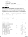
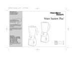
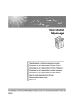
Yaesu FT-101 HF Transceiver Home Page, NW2M
1 di 14
http://www.qsl.net/nw2m/
The purpose of this page is to capture and document the Yaesu FT-101 series radios during the 1970's. It has taken me 12
years to collect a transceiver and every accessory to make a "complete station". I encourage your feed back, corrections,
and additions. I am not an Electrical Engineer, so I can not help with specific repair or substitution problems. I simply don't
have access to this type of material or equipment. My objective is to document the Yaesu FT-101 era and to provide a
detailed understanding so that the value of this equipment can be realized.
Thanks, Al-NW2M
FT-101 History
FT-101 Model Numbers
Physical Construction
Advertised Features
General Specifications
A "Complete" Station
Station Accessories
Tune-up Procedures
Known Modifications
6JS6C Tubes
Basic Alignment Points
QST / 73 / CQ
AM Operation
Weights and Shipping
Repair Facilities
Original Prices
Mobile Operations
Fox-Tango Newsletters
Comments/Corrections
Credits
About the author - Al Rabassa, NW2M
The FT-101 series of transceivers first appeared outside of the United States in 1970 and then inside the United States in late
1971. It gained overnight approval of amateur radio operators for its quality of signal, flexibility and for professional
attention to workmanship and design. The modular design of 10 solid state circuit boards on a common chassis with a tube
amplifier caught the eye of discriminating hams world wide.
It was a strong performer. Although far from perfect, the first FT-101's suffered from intermod when strong signals were
present during receive and generated spurs on transmit. Hams began to investigate these problems and offer improvements
to existing circuit design. The factory responded with a major modification which significantly improved the receiver of the
early FT-101's. The serial number revealed which transceiver was "early" and "late". So that the "early" FT-101 hams would
not feel obsolete, Yaesu offered the entire modification which made an "early" into a "late" and sold it as a kit along with a
25 page instruction guide. Problems began as many hams lacked the proper test equipment and the know-how needed to
make such an upgrade. After months of fighting with customers, Yaesu withdrew the kit (MIR-1 Modification Kit) and
would only install it at their factory. Adding to the confusion was the fact that there were five (5) different sub-models
within the "early" FT-101 series, the last being the FT-101 "late" model. The situation arose where identical FT-101 radios
sat side by side with the only indication of the internal layout was by the serial number.
Additional improvements were made and with the addition of the 160 meter band, the FT-101B was released. Yet more
20/07/2010 12.36
Yaesu FT-101 HF Transceiver Home Page, NW2M
2 di 14
http://www.qsl.net/nw2m/
improvements and the addition of a real "RF" speech processor led to the release of the FT-101E model. The "E" model was
fully refined with all of the previous problems having been worked out. This was the most popular and the most produced
model by Yaesu in the FT-101 series. Three models of the "E" were released. The "E" model with all options, an "EE"
(economy) model lacking the speech processor, and the "EX" (extreme economy) model lacking speech processor, 160M
crystal, DC options, and microphone. Last in the series was the "F" model which contained all of the modifications,
improvements and options throughout the series. Only a few of the "F" models were made which also included an "FE"
(economy) and "FX" (extreme economy) model. With fierce competition in the HF market, WARC bands on the horizon, IF
shift, AF Notch/Peak, and digital readouts, the FT-101 series moved quickly to the analog "Z" model and then to the digital
"ZD" models. The original FT-101 series lasted for 8 years, beginning in late 1971 and lasting through 1979. It was an
exciting time for the FT-101 radios and their owners.
There were no "A", "C", or "D" models produced.
A publication called the Fox-Tango Newsletter captured the "diary" of the FT-101's for all time. Ten publications per year
offered thousands of FT-101 owners the opportunity to share problems, solutions, and performance data. The Fox-Tango
Newsletters lasted for 14 years. It is the largest collection of user data and factory support information for any radio at any
time. It has been preserved and full copies are still available today. Truly a testament to the era and popularity of these
radios, even today.
There are many models which proudly display the FT-101 logo. Please be sure that you know which model you have, know
its operating capabilities, and limitations. Normally, the longer the model number is, the less capabilities it has for that
model. The last 5 digits represent the serial number. Any serial number prefix is for factory control and routing. Here is the
complete list:
FT-101 - "Early" model
1971, first offering in United States.
Serial numbers below 25,000.
Known for strong receiver overload, TX spurs, and audio problems.
80-10 meter transceiver.
FT-101 - "Late" Model
Serial numbers above 25,000.
Major modifications to receiver, Regulator, IF and audio boards.
80-10 meter transceiver.
There were five FT-101 sub-models known: (based upon MK-160 160 Meter kit information)
Mark 0: Serial numbers 06000 and below. First "Early" models during 1970.
Mark 0A: Serial numbers 06001 to 07991. Transitional.
Mark I: Serial numbers 08001 to 23999. Most common "Early" model.
Mark II: Serial numbers 24000 to 24999. Transitional models with 160M tank circuit.
Mark IIA: Serial numbers 25000 and up. First "Late" Models.
Beware: Early and Late model circuit boards may not be fully interchangeable.
FT-101B - "Early" Model
Serial numbers below 6,000.
Improved IF (PB1183B) and Audio (PB1315), and Blanker (PB1292) boards.
160-10 meter transceiver.
FT-101B - "Late" Model
Serial numbers 6,001 and up.
Improved Regulator (PB1314A), IF (PB1180B), and Audio (PB1315A) boards.
160-10 meter transceiver.
FT-101BS
Special FT-101B model for Japan Market.
Single 6JS6C tube, 50 watt output.
20/07/2010 12.36
Yaesu FT-101 HF Transceiver Home Page, NW2M
3 di 14
http://www.qsl.net/nw2m/
FT-101E
160-10 meter transceiver.
RF Speech Processor.
Three sub-models:
"Early" - S/N 15,000 and lower. (PB1494) Processor
"Mid" - S/N 15,001-20,500. (PB1534) Processor
"Late" - S/N 20,501 and up. (PB1534A) Processor, (PB1547A) Regulator, (PB1183C) IF, (PB1315B) Audio,
(PB1582) Blanker.
FT-101EE
Economy FT-101E model.
All FT-101E specifications except,
No Speech processor (available as an option).
FT-101EX
Extreme Economy FT-101E model.
All FT-101E specifications except,
No Speech Processor (available as an option).
No DC Converter for Mobile use (available as an option).
No Microphone, DC cord, or 160M crystal, 10A crystal only.
FT-101ES
Special FT-101E model for Japan Market.
Single 6JS6C tube, 50 watt output.
FT-101F
Latest in the FT-101 series.
160-10 meter transceiver. 11 meters as AUX position.
Improved (PB1582) Noise Blanker.
Speech Processor and DC Converter.
FT-101FE
Economy FT-101F model.
All FT-101F specifications except,
No Speech Processor (available as an option).
FT-101FX
Extreme Economy FT-101F Model.
All FT-101F specifications except,
No Speech Processor (available as an option).
No DC Converter for Mobile use (available as an option).
No Microphone, DC cord, or 160M crystal, 10A crystal only.
There were no "A", "C", or "D" models ever produced.
FT-101 Board Complement by Model Number
FT-101 Version
VFO
REG
HF/IF
LO/IF
AUDIO
RF
MOD
RECT
FT-101 (Early)
S/N 25,000&Down
PB1056 PB1079A PB1084C PB1080A PB1081C PB1077B PB1078A PB1076A
FT-101 (Late)
S/N 25,001&Up
PB1056 PB1185
PB1180
FT-101B (Early)
S/N 6,000&Down
PB1056 PB1185
BLANKER PROCESS
Part of
PB1080A
None
PB1189 PB1181A PB1184 PB1076B
PB1182
None
PB1180 PB1183B PB1315 PB1181B PB1184A PB1076B
PB1192
None
FT-101B (Late)
S/N 6,000&Up
PB1056 PB1314A PB1180B PB1183B PB1315A PB1181B PB1184A PB1076B
PB1192
None
FT-101E/EE/EX
(Early)
S/N 15,000&Down
PB1056 PB1314A PB1180B PB1183B PB1315A PB1181B PB1184A PB1076B
PB1192
PB1494
PB1183
20/07/2010 12.36
Yaesu FT-101 HF Transceiver Home Page, NW2M
4 di 14
http://www.qsl.net/nw2m/
FT-101E/EE/EX
(Mid)
S/N 15,000-20,000
PB1056 PB1314A PB1180B PB1183B PB1315A PB1181B PB1184A PB1076B
PB1192
PB1534
FT-101E/EE/EX
(Late)
S/N 20,001&Up
PB1056 PB1314A PB1180B PB1183C PB1315A PB1181B PB1184A PB1076B
PB1582
PB1534A
FT-101F/FE/FX (All)
PB1056 PB1547 PB1180B PB1183 PB1315B PB1181B PB1184A PB1076B PB1582B PB1534A
S/N All Numbers
The FT-101 is a hybrid radio that employs a solid state transmitter, receiver, and a tube final amplifier. The solid state
features of the radio offer high-performance, low-current characteristics, while the tube amplifier provides a nearly "bulletproof" transmitter and tuner stage.
The tube amplifier consists of a 12BY7A pre-driver stage that feeds a pair of 6JS6C tubes providing a nominal output power
of 130 watts PEP SSB, 90 watts CW, 40 watts AM. The 6JS6C tubes are matched to 50 Ohms through a conventional
pi-output network. The pi-network transforms the 3000 ohm output impedance of the tubes to a 50 Ohm feed system,
provides harmonic attenuation, and can actually match to a variety of output impedances from 25 to 100 Ohms with ease.
The transceivers were made with plug-in boards that could be sent to the factory for replacement or repair. This modular
design was unprecedented in the amateur community, which explains why so many FT-101's are still in use today. In fact,
board extenders could be purchased to extend any board above the main chassis for measurement, alignment, and repair.
For any plug-in board, all voltages, grounds, and signal traces were routed through a single edge connector (facing down into
the main chassis). This removed the need for wires and cables to these circuit boards. This yielded a clean and trim internal
upper chassis. The bulk of the wiring harness is below the deck of the main chassis where all main circuit board edge
connectors are fed. Yes, there are many wires!
FT-101 Block Diagram 54k
FT-101 Top Chassis Photo 106k
FT-101 Bottom Chassis Photo 91k
Please print landscape, margins set to 0.25", 300 or 600 DPI gray scale
The most complicated device in this radio is the Band Selector Switch. This is a 12-position rotary switch that runs from the
front of the radio to the back. It has 13 sections (wafers A thru M) which route everything from DC voltages, oscillator
sections, crystals, tuning circuits, and RF Power in the high-voltage tank and output circuits. One band selector switch
position is used for: 160M, 80M, 40M, 20M, 15M, 10A, 10B, 10C, 10D, 11M or AUX, and WWV receive-only. Each
position allows the main VFO to cover 500kHz on any band.
The entire transceiver was made of metal. Covers, chassis, shields, shafts, etc., are all metal. Even the plastic RF/S-meter
trim and knobs have brass metal inserts. At 35 pounds, there is a lot of metal in this radio! The 10 major circuit boards are
mounted with threaded hardware to the main chassis. Very rugged indeed. A clear plastic sheet covers the entire painted
surface of the faceplate. A well-cared-for FT-101 will still have this clear plastic front.
Because critical circuit designs were kept to a manageable size, hams had no problem in offering circuit changes, isolating
and repairing problems. This knowledge base was so active that in January 1972, Milton Lowens WA2AOQ, founded the
International Fox Tango Club and the Fox Tango Newsletter. The Fox Tango Newsletters were published for 14 years
covering the early FT-101's thru the latest Yaesu Transceivers in 1985. By then, surface mount technology and circuit
complexity outpaced many ham's ability to maintain this level of equipment. In doing so, new chapters in circuit densities,
solid state transmitters, and LSI chips were born, which closed the door (and the covers) to many radios.
Built-in AC and DC power supplies.
True RF Speech Processor.
20/07/2010 12.36
Yaesu FT-101 HF Transceiver Home Page, NW2M
5 di 14
http://www.qsl.net/nw2m/
Solid state VFO, 1kHz resolution.
Modulation modes - USB, LSB, CW, AM.
Built-in, adjustable, VOX.
Adjustable CW Side tone.
Selectable 25kHz and 100kHz calibrator/marker.
RIT control +/- 5kHz range.
WWV reception for time and fine frequency calibration.
Built-in speaker.
Eight pole SSB filter. CW filter optional.
Complete line of station accessories providing 160M thru 2M coverage.
Arguments arise when hams talk about a "complete" FT-101 station. Let's set the record straight. Based upon the Yaesu
Service manual "Accessories" , a complete FT-101 station will have the following:
FT-101 Transceiver or FL-101/FR-101 Twins
FV-101 Remote VFO
FL-2100 Linear Amplifier
SP-101PB Phone Patch with Speaker or SP-101 Speaker-only
YO-100 or YO-101 Monitor Scope
YC-601 Digital Display Unit
FTV-250 2 Meter Transverter
FTV-650 6 Meter Transverter
YP-150 Dummy Load / Watt Meter
YD-844 Dynamic Desk Microphone
QTR-24 World Clock
This rounds out the field, and is supported in the Yaesu Manuals and advertising in QST. There may be other items made by
Yaesu during this period, but no mention is made in any of the FT-101 service manuals or documentation. Yaesu Service
Manual pages 1-31 thru 1-39 cover the above items as Accessories. Options, included the CW Filter, Fan, Mobile Mounting
Bracket, etc.
Yaesu made an entire suite of accessories to complement any FT-101 operator's station. Each accessory has been
thoroughly crafted and integrated to extend any operating capability. Adding station accessories allows complete band
20/07/2010 12.36
Yaesu FT-101 HF Transceiver Home Page, NW2M
6 di 14
http://www.qsl.net/nw2m/
coverage from 160 meters on HF through 2 meters (USB, LSB,CW, AM). Here is a list of each accessory, description, and
specifications.
FL-2100B/F/Z Linear Amplifier
| FL-2100 Hook-up diagram | FL-2100 Schematic A | FL-2100 Schematic B | FL-2100 Transformer Wiring |
The FL-2100B/F/Z is a conservatively rated matching amplifier for the FT-101 series. The amplifier features two
rugged 572B carbon plate tubes in a Class B grounded-grid circuit with individually tuned input coils for each band.
The FL-2100B/F/Z operates with dual cooling fans and a solid state power supply. Dual interlocks offer safety and
shock protection. An automatic changeover circuit biases the tube to cut-off on receive to maximize tube life and
minimize heat. A bifilar wound, ferrite chokes ensure minimum RF transfer to the power source. Conservatively rated
at 1200 watts PEP input power on 80 through 10 meters. Dual illuminated front panel meters provide continuous
monitoring of plate current, voltage, relative output, and SWR. A "standby" switch allows the amplifier to be
bypassed with primary power enabled and tubes fully heated for operation. Connections to the FT-101 transceiver
include TX/RX relay control and ALC control voltages. Such control lines are typical for all FT-101 accessories.
There were three FL2100 models produced: FL2100B, FL2100F, and FL2100Z. The FL2100 B and F models cover
80-10 meters, the Z model includes 160 and WARC bands.
FL-2000B/F/Z Specifications:
Frequency Range*: 3.5-4 MHz, 7.0-7.5 MHz, 14.0-14.5 MHz, 21.0-21.5 MHz, 28.0-29.9 MHz.
* The FL2100Z covers 160 Meter Band 1.8-2.0 MHz, 18 MHz, and 24 MHz WARC bands.
Plate Input Power: 1200 watts PEP on SSB, 800 watts on CW, and 600 watts AM.
Drive Requirements: 30 to 100 watts.
Input Impedance: 50 Ohms, unbalanced.
Output Impedance: 50 Ohms, unbalanced, SWR less than 2:1.
Distortion Products: -30dB at 1200 watts input.
Noise Level: 40 dB below single tone carrier.
Circuitry: A pair of 572B in grounded grid, class B.
Power Requirements: 100/110/117 VAC at 18 amps. 200/220/234 VAC at 9 amps.
Size: 6-1/2"h x 15"w x 12"d
Weight: 41 lbs
FV-101B External VFO
Adding the FV-101B External VFO to your station opens up a new world of operating flexibility. DX'ers will really
appreciate this combination. The FV-101B features the same factory sealed, solid state, 1kHz resolution, VFO that is
found inside the FT-101 transceiver. This flexibility allows for "split" operation for separate transmit and receive
frequencies in any band. Regardless of VFO mode, the exact transmit and receive frequency are available for the
Digital Display (YC-601 or DD-1) unit. Please note that any frequency split occurs within the same band. The
Remote VFO does not offer cross-band operation. Four VFO modes are supported:
1.
2.
3.
4.
Transmit and Receive from Main VFO (normal mode)
Transmit from Main VFO, Receive from Remote VFO
Transmit from Remote VFO, Receive from Main VFO
Transmit and Receive from Remote VFO
FV-101B Specifications:
Frequency Range: 8.7 to 9.2 MHz (500kHz tuning range)
Frequency Stability: Within 100 Hz in any 30 minute period after warm-up
Power Source: Remote VFO Connection on the rear of the FT-101 transceiver
Size: 6-1/2"h x
Weight: 7-1/2 lbs
YO-100 / YO-101 Monitor Scope
| YO-100 Schematic A | YO-100 Schematic B |
Adding the YO-100 Monitor Scope allows you to monitor and adjust your transmitter for the cleanest signal possible.
Compatible with virtually any transmitter or transceiver, the Station Monitor features a wide range of inputs for all
mode monitoring, even RTTY. A built-in 1500 Hz and 1900 Hz tone generators adds to the versatility of this
accessory. The two-tone generator generates the proper audio signals to perform "trapezoidal" pattern testing for
transmitter linearity. A full compliment of front controls allows operator control of all key adjustments. The YO-101
is a solid state version of the YO-100.
20/07/2010 12.36
Yaesu FT-101 HF Transceiver Home Page, NW2M
7 di 14
http://www.qsl.net/nw2m/
YO-100 / YO-101 Monitor Scope Specifications:
Vertical Trace Performance
Sensitivity: 200 mV P-P/cm
Frequency Response: Direct 10Hz to 60MHz
Horizontal Trace Performance
Sensitivity: 300 mV/cm
Frequency Response: 10Hz to 16kHz
Sweep Frequency: 10 Hz to 10 kHz
Two-Tone Generator Performance
Frequency: 1500 Hz and 1900 Hz, Independently selectable
Output Level: 50 mV
Power Requirements: 100/110/117/200/220/234 VAC 50/60 Hz
Size: 6-1/2"h x
Weight: 13 lbs
YD-844 Dynamic Base Microphone
The YD-844 is an attractive and functional necessity for serious base-station operation. The unit is made of heavy
cast metal which rests solidly at your operating position. The microphone element is dynamic (voice-coil) and is
balanced (output levels and impedances) for use with the FT-101 transceiver. Two PPT (push to talk) buttons are
available on the YD-844 microphone. One button is a momentary-switch which must be depressed to activate the
PTT relay, the second button has a lock feature which allows hands-free operating (while still transmitting via PTT).
The microphone element is always connected to the FT-101 so that VOX operations are available without depressing
any microphone PTT buttons. The FT-101 transceiver has three transmit options: 1-MOX (Manually Operated
transmitter), 2-PPT (Push To Talk), and 3-VOX (Voice Operated Transmitter). These three options are available on
the front panel of the FT-101 Transceiver via toggle switch. The YD-844 is available in both high and low
impedances. The microphone cord is a 3' coiled, 4 conductor (one shielded) cable terminating into a 4-pin female
connector.
FT-101 Microphone Connection Detail
YD-844 Specifications:
Impedance: 500 Ohms at 1kHz, or 50k Ohms at 1kHz
Output: 50mV nominal
Frequency Response: 50Hz-10kHz nominal
Directivity: Uni-directional
Size: 9" x 3" x 6"
Weight: 1-3/4 lbs
QTR-24 World Clock
The QTR-24 World Clock is a 12 and 24 hour format clock. The standard clock movement (hours, minutes, seconds)
is represented in the classical 12 hour format. An outer ring depicts time in a 24 hour format. The first 12 hours are
shown in white to depict daylight and the other 12 in black. The outer-most perimeter of the clock face has the names
of the major cities throughout the world in each of the 24 global time zones. As the 24 hour ring passes a group of
cities, you can easily see their UTC time and a day/night indication. The QTR-24 has three adjustments on the rear.
One for time (basic movement adjustments), one for the 24-hour ring, and one for fine-time adjustment. The QTR-24
can be adjusted to be accurate within 60 seconds per month.
A 24 hour station clock is a must-have accessory for any operator. The current name and format for world time is
called Universal Time Coordinate (UTC). It has also been known over the past years as Greenwich Mean Time
(GMT), and the military term ZULU (Z). All world time is represented in a 24-hour format based upon the global
starting point in Greenwich, England (UK). The UTC time standard does not adjust for Daylight Savings Time in the
United States.
Accurate time reception can be found by tuning to WWV (10.000MHz) on the FT-101 transceiver. Alternate
frequencies for WWV and WWVH are 2.500, 5.000, 10.000, 15.000, and 20.000 MHz. All time formats are AM
broadcasts. CHU in Ottawa, Ontario (Canada) can be found in the 40 meter band 7.335 MHz, 3.330 MHz, and 14.670
MHz. The WWV (male voice) originates from Ft. Collins, Colorado (USA). The WWVH (female voice) originates
from Kauai, Hawaii (USA). The ultra-high accuracy of the WWV 10.000MHz signal is also used to calibrate
20/07/2010 12.36
Yaesu FT-101 HF Transceiver Home Page, NW2M
8 di 14
http://www.qsl.net/nw2m/
(zero-beat) the FT-101 internal marker located on the Regulator Board (TC1).
QTR-24 Specifications:
Time Format: 12 and 24 hour formats
Accuracy: Continuously adjustable, 60 sec/month, nominal
Power: 1.5V, single C-cell battery, replace yearly
Internal Movement: Oscillating spring wheel
External Movement: Hours, minutes, seconds, 24 hour ring day/night indication
Construction: Black plastic frame, glass face with chrome trim
Size: 6" diameter, 2-1/2" deep
Weight: 1 lb
Mounting: Wall mount or desktop with tilt-bail
YP-150 Dummy Load / Watt Meter
The YP-150 is a 50 Ohm dummy load with a built-in RF watt meter. This unit provides a 50 Ohm resistive load to any
transmitter operating from 1.8Mhz thru 200MHz. A single PL-259 plug on the rear panel provides the unbalanced
input to this unit. The YP-150 is powered by a 117V AC source to run an internal cooling fan to remove heat from the
50 Ohm non-inductive load. Although YP-150 is powered, the front panel meter is not illuminated. A four-position
switch allows accurate RF power measurements from 0-6 watts, 0-30 watts, and 0-150 watts. The fourth position is
the OFF position which removes power to the fan and disconnects the power measuring unit. The YP-601 can be
operated without AC power, but this practice is not recommended, as excessive heat can damage the resistive load.
There is no provision for an RF "bypass", therefore this unit is best suited for bench testing and alignment procedures.
YP-150 Specifications:
Frequency Range: 1.8MHz to 200MHz
Power Scales: 0-6 watts, 0-30 watts, 0-150 watts
SWR: Less than 1.2:1 at 146MHz
Accuracy: Better than 10% of maximum scale
Meter: Logarithmic scale
Connection: Single PL-259, unbalanced
Power: 117V AC for internal cooling fan
Size: 6-1/2"h x 4"w x 11"d
Weight: 4-1/2 lbs
SP-101 External Speaker and SP-101PB External Speaker and Phone Patch
| SP-101PB Hook-up diagram | SP-101SP Schematic |
The Yaesu SP-101 and SP-101PB provide audio fidelity that is unmatched by the internal speakers found in most
conventional HF transceivers. Although all of the FT-101 series of transceivers have internal speakers (some early
radios did NOT have speakers!), the SP-101 External Speaker provides an audio fidelity and presence which cannot
be matched with a small 3" internal speaker. The SP-101 internal speaker uses the entire speaker enclosure to produce
pleasing tonal qualities needed for the reception of rich AM, sharp SSB, and narrow CW. There are no audio filters in
the SP-101 to change the audio properties originating from the FT-101. Connection to the SP-101 is with shielded
RCA connectors. It is strongly suggested that small diameter coax or highly shielded audio be used to ensure shielding
from the transceiver to the remote speaker. The SP (speaker output) jack on the FT-101 has some RF suppression,
and is one of the first places to look for feedback and hum especially at kW levels during transmit.
The SP-101PB contains all of the excellent audio properties and characteristics as the SP-101 speaker-only model
with the addition of a hybrid telephone-patch circuit. This circuit allows the FT-101 transceiver to be interconnected
to your telephone circuit to allow telephone calls to be placed with over-the-air stations. The SP-101PB has two level
controls to ensure proper audio levels are presented to the telephone lines. A built-in VU-meter is used monitor the
phone-input levels. Connection to the telephone line is via (two-wire) twisted pair (normally red and green wires).
NOTE: When using the phone patch, you are engaging in third-party traffic in which you are the control operator.
The US does not have 100% third-party traffic agreements with all countries. Example: I was unable to make a phone
patch for a ham on a small sailboat on vacation in the Bahamas/C6 to their parents living 3 miles from my house! The
US does not have third-party traffic agreements with the Bahamas. Beware!
SP-101 and SP-101PB Specifications:
Speaker Impedance: 4 Ohms
20/07/2010 12.36
Yaesu FT-101 HF Transceiver Home Page, NW2M
9 di 14
http://www.qsl.net/nw2m/
Speaker Size: 4" x 6"
Audio Power: 3 Watts RMS
Patch Input: 4 Ohms, 600 Ohms (RCA, Shielded)
Patch Output: 600 Ohms, 50K Ohms (RCA, Shielded)
Telephone Connection: Unshielded Twisted-Pair (UTP), Red-Green or Black-Yellow pairs
Patch Performance: 300-4000Hz, 600 Ohms balanced, complies with FCC Part 68.
Size: 6-1/2"h x
Weight:
So how much did it cost? Here are some prices from QST during the 1970's for each of the FT-101 transceivers and
associated accessories. It is difficult to accurately depict prices for each and every month spanning 9+ years. Even with this
data, there are dealers offering close-out prices which can be $100-$125 under other dealers who wish to continue selling
the product line. In some cases the "list" prices are advertised with the note to "call for best price", making it extremely
difficult to accurately gauge exact prices. Prices marked with an asterisk (*) denote a close out price or inventory reducing
price. Normally prices will vary only a few dollars between dealers in the same issue. More sources and lists will follow- as I
find the QST issues for the 1970's.
Item
Price Price Price Price Price Price Price Price Price Price
Model
Description
Q3/71 Q3/72 Q3/73 Q3/74 Q3/75 Q3/76 Q3/77 Q3/78 Q3/79 Q3/80
---------|-----------------------------|-----|-----|-----|-----|-----|-----|-----|-----|-----|-----|
FRdx400
80M-10M All Tube Receiver
$359
$339
FRdx400SD 80M-10M+6M+2M All Tube Receiver
$399
FLdx400
80M-10M All Tube Transmitter $299
FRdx401
80M-10M All Tube Receiver
FLdx401
80M-10M All Tube Transmitter
FTdx401B
80M-10M All Tube Transceiver
$599
FTdx560
80M-10M All Tube Transceiver $450
FTdx570
80M-10M All Tube Transceiver
$550
FL2000
80M-10M Linear for dx Series $299
$339
FT-101
80M-10M Transceiver
$499 $560
FT-101B
160M-10M Transceiver
FT-101E
160M-10M Transceiver
$649
$729 $799 $695*
FT-101EE 160M-10M Transceiver
$649 $759
FT-101EX 160M-10M Transceiver
$589 $699
FT-101ES 160M-10M Transceiver(50 watt version for Japan market)
FT-101F
160M-10M Transceiver
$799
FT-101FE 160M-10M Transceiver
$759
FT-101FX 160M-10M Transceiver
$699
FT-101Z
160M-10M Transceiver
$749
$599*
FT-101ZD 160M-10M Digital Transceiver
$895 $749
FT-101ZD 160M-10M Digital Transceiver (WARC)
$799
FT-901D
160M-10M Digital Transceiver (WARC)
$1299
FT-901DE 160M-10M Digital Transceiver (WARC)
$1149
FT-901DM 160M-10M Digital Transceiver (WARC)
$1299 $1459
FL-2100B Linear Amplifier 80M-10M
$339
$399 $479
FL-2100F Linear Amplifier 80M-10M
$399*
FL-2100Z Linear Amplifier 160M-10M
$399*
FV-101B
Remote VFO
$99
$109 $135 $116
SP-101
Speaker-Only
$19
$22
$25
$22*
SP-101PB Speaker with Telephone Patch
$59
$59
$67
$57
FTV-650
6 Meter Transverter
$149
$199 $235
FTV-250
2 Meter Transverter
$199 $275
$225*
YC-601
Digital Display (Yaesu)
$169 $199 $205
YO-100
Station Monitor Scope (Tube Model)
$199 $233 $240
YO-101
Station Monitor Scope (Solid State)
$320
$199*
FR-101
Analog Receiver 160M-2M
$489
FR-101
Digital Receiver 160M-2M
$599 $599 $549
FR-101S
Analog Receiver 160M-2M
$599 $449 $349*
FR-101SD Digital Receiver 160M-2M
$749
FL-101
160M-10M Transmitter
$525 $575 $499 $399*
YP-150
Dummy Load - Watt Meter
$86
$78
$79*
RFP-101
Speech Processor
$79
$79
YD-844
Base Station Microphone
$29
$29
$29
YD-846
Hand Microphone
$16
$16
QTR-24
World Clock
$30
$35
$29*
FA-9
Fan
$19
$15
$20
20/07/2010 12.36
Yaesu FT-101 HF Transceiver Home Page, NW2M
10 di 14
MMB-1
XF-30C
XF-30B
DC-1
Crystals
DD-1
http://www.qsl.net/nw2m/
Mobile Mount for FT Series
CW Filter 500 Hz
AM Filter 6kHz
DC Converter for EX Models
Any FT-101 Crystal 160M-10M
Digital Display (Spectronics Model)
$19
$45
$19
$40
$5
$169
$45
$5
$169
$23
$40
$40
$50
$5
* - Indicates Advertisers offering "close-out" prices to reduce stock.
The 6JS6C tube is a TV Deflection Tube, or "Sweep Tube". Although not meant for transmitting it exhibits sufficient
performance for RF operation through 30 MHz. Each tube can dissipate 30 watts of plate power, 5.5 watts of screen power,
filament voltage of 6.3 volts at 2.25 amps, and has a Cin/Cgp/Cout of 24/0.7/10 pf respectively. The base is a 12-pin socket.
6JS6C Diagram
There will come a time when the finals in your FT101E will need replacing. The FT-101 transceivers were originally
equipped with 6JS6C tubes manufactured by NEC and Toshiba. Other manufacturers tube properties are slightly different
from the original 6JS6C tubes. Therefore, a simple modification to the neutralization circuit must be made to the final
section of the transceiver. The modification consists of replacing the fixed value 100 pf 1000 VDC mica capacitor with a 10
pf 1000 VDC mica capacitor. This capacitor, C125, is in series with the 10 pf variable neutralizing capacitor off of the plate
circuit.
Schematic of FT-101 Power Amplifier Circuit
If this modification has not already been completed on your rig, be sure to use a mica or silver mica of at least 1000 VDC.
Do not substitute a different type because the heat in the final compartment will change the value, and your tubes will fail
prematurely. Also, be very careful to keep all leads short and in exactly the same orientation as the original capacitor.
Before re-neutralizing, open the variable neutralizing capacitor all the way to minimum engagement and follow the
neutralizing instructions in the manual. While dipping the PLATE, remember to adjust the neutralizing capacitor for equal
value meter reading "dips" (Ic meter position) on both sides of the peak when tuning the PLATE control. WARNING! You
are tuning a capacitor in the High Voltage compartment, +600 Volts are present! Always use non-metallic tuning tools. After
neutralization, reset the bias to 60ma with CARRIER and MIC settings at minimum.
List of known 6JS6C tube suppliers:
SND Tube Sales
Radio Electric Supply
Com-West Radio Systems
ESRC
AmpDoc
Electron Tube Enterprises
Vacuum Tubes, Inc.
BB&W
LynTec NOS Electron Tubes
Vintage Electronics
Brent Jessee Recording
Or, Search the web yourself -> 6JS6C
QST- The following performance data is provided by the American Radio Relay League (ARRL) and their publication QST.
A full copy of this table was found on the Technical Information Service section on the ARRL web page. The table depicted
over 60 radios and their performance data. I have shown only the Yaesu radios from the 1970's that apply to this web page.
QST
|
QST Reviews of Amateur HF Transceivers
Xmtr
|
Rcvr
20/07/2010 12.36
Yaesu FT-101 HF Transceiver Home Page, NW2M
11 di 14
http://www.qsl.net/nw2m/
Rig
Review| Harm.
Spurs
IMD | Min Sig BlkRng IMD DR 3rdO Icpt
Issue | dBpep
dBpep
dBpep| dBm
dB
dB
dBm
------------------------------------------------------------------------Yaesu:
FT-101B 02/74
FT-101E 09/76
-34
-141
108
81
FT-101Z 12/79
-45
-38
-139
112
78
-22
FT-301 10/77
-55
-68
-40
-133
100
75
FT-901 11/78
-46
-57
-38
-137
114
85
If you have ever purchased a FT-101 transceiver without the Instruction Manual, you know it can be very intimidating to
operate until you perform the tune-up process a time or two. Without 'tuning up' your transmitted and received signals really
suffer AND could actually damage the tubes in the power amplifier. I always suggest that you obtain the Instruction Manual
for any FT-101 radio or accessory you own. Even older radios have web pages that can provide you copies at very
reasonable rates. An Instruction Manual was made for each and every FT-101 radio and accessory. They are worth every
penny. No excuses!
The FT-101 series is a very mechanical radio. The size, selection, and operation of this rig allow for very high-Q circuit
tuning. It is a very strong point with the FT-101 series. As with any high-Q circuit, it must be continuously tuned for
maximum efficiency. Once learned, it takes only a few seconds to perform. You should re-tune anytime you change bands,
change antennas, or move a significant distance (in frequency) from where you last tuned up. This may be as large as 200
kHz on the 10 meter band (10-15 turns of the VFO dial) or as little as 15 kHz on the 160 meter band (one turn of the VFO
dial).
Before you begin, you should allow the rig to warm up (with the heaters on) for at least 15 minutes. This allows the rig to
become frequency and temperature stable. Put the Meter switch into the 'IC' position with the CARRIER and MIC control
fully counter-clockwise. Throw the MOX switch to engage the transmitter and read the meter that is now displaying the
idling current. The current should read 60ma on the scale. If it does not, adjust the BIAS control until 60ma is obtained.
Move the Meter switch to ALC and ensure a full meter deflection to the right. Adjust the ALC control as needed. Return
the MOX switch to normal PTT.
Please remember to tune-up into a well-matched antenna system or dummy load representing a 50 Ohm load. Keep all
tune-up steps to under 10 seconds of transmitting to prevent damage to the Power Amplifier tubes! After each 10 second
transmission, allow the tubes to cool for a few seconds. Then repeat.
The earlier FT-101 manuals used a tune-up procedure which 'peaked' the output (PO) while 'dipping' the grid (Ic) current.
By the FT-101F series, the procedure was simply a 'peaking' (PO) process as depicted in the Instruction Manual. With a
little practice, you will be able to perform these procedures within 10 seconds. Really!
Tune-Up Procedure for SSB, CW, and AM:
After a 15 minute warm-up, and Idle Current confirmed at 60 ma:
Select the band and general operating frequency to be used.
Place the Meter switch in the Power Out (PO) position.
Rotate the PRESELECTOR for maximum receiver noise/signal output.
Place the CARRIER control to position 4 and MIC control to minimum.
Momentarially engage the MOX transmitter control for a maximum of 10 seconds.
Adjust the PRESELECTOR, TUNE, and PLATE controls for maximum meter deflection.
Disengage the MOX transmitter control and let the rig cool for a few seconds.
Increase the CARRIER control two units and repeat.
NOTE: If using AM, adjust CARRIER for 30 watts and increase the LOAD control one unit.
Adjust CARRIER, MIC, and PROCESS controls for the proper output as desired. Monitor the Meter for grid current (Ic)
and ALC levels (ALC) to ensure that you are not over-driving the transmitter. Both will greatly shorten tube life, cause
distorted transmitted audio, and is the prime source of television interference (TVI).
20/07/2010 12.36
Yaesu FT-101 HF Transceiver Home Page, NW2M
12 di 14
http://www.qsl.net/nw2m/
One of the most misunderstood and mistuned modes available on the FT-101 transceivers is the AM (Amplitude
Modulation) transmitter. (Second only to the RF Speech Processor!) The FT-101 has one of the best on-air signals for AM
that you may ever find in a stock radio. It is also one of the easiest to make a mistake. The most common mistake is
measuring AM power the same way that you measure SSB or CW signals using a watt meter. AM is very different.
The most common mistake is running too much carrier power in AM mode. The FT-101 can only deliver 30-40 watts of AM
carrier in linear service. The reason for this is that an AM signal contains a steady carrier and two sidebands that contain
your audio. The amount of RF power in this modulated AM "envelope" is actually 4-times the carrier. This means that a
modulated AM signal with a 30-watt carrier is actually transmitting 120 watts of power. This is the amount of power needed
from the power supply to transmit this signal. It is also approaching its absolute power limit. The same is true with the
matching FL-2100B amplifier. A 300-watt carrier contains 1200 watts of RF power when fully modulated. There is nothing
worse than "cooking" a FT-101 by running AM with a 100 watt carrier. The power supply, tubes, and amplifier components
cannot deliver 400 watts of power, are run continuously beyond their maximum rating, and for long periods of time. Beware
when purchasing one of these 11 meter 'cooked' radios!
FT-101 Modifications
More info to follow.....
Alignment Points and Procedures
More info to follow.....
Buy / Swap / Sell Suggestions and References
More info to follow.....
Background: As a buyer or seller, you need to know the fair market value of shipping so that you can finalize the exact
cost of any deal. There should be no surprises as you hand over the box to be shipped, and no surprises when the box gets
opened. The following information will allow for accurate shipping costs, assuming you have weighed the package carefully,
for delivery anywhere in the United States or overseas.
Sizes and Weights: The sizes and weights for each piece of Yaesu equipment is listed above. None of the Yaesu
transceivers or accessories exceed the size and weight limits imposed by any of the major common carriers, such as UPS.
Shipping should be a very straightforward process, and with a little planning, your package should arrive in the same
condition as it was shipped.
Estimating Final Weight: Accept the fact that shipping will add 20%-25% to the actual weight of any unit. Yes, a 30
pound FT-101E transceiver with manual and power cords will actually weigh 38 pounds ready to ship. A two pound
YD-844 microphone will weigh 3-4 pounds if packed properly. The heaviest in the series, the FL-2100 amplifier (41 lb.) will
tip the scales at 52 pounds at the counter! Don't underestimate the weight of shipping!
Packing Considerations: Remember that you are responsible for ensuring that the equipment is packed properly and safely
for its journey. The longer the trip the better it must be packed, especially overseas. NEVER use newspaper for any of
packing material. It is not resilient to compression, it holds moisture, and will leave ink on painted and plastic surfaces.
When possible, use the original Yaesu packing box and materials. Prior to shipping any unit, remove all AC cords,
microphones, accessory plugs, and the brass spinner on the main VFO dial. Do not use tape on any plastic or painted
surface. Ensure that all covers are on tight. Put the unit in a plastic bag (as a moisture and dust barrier), and then wrap in
bubble wrap. Select a box which allows at least 2" on each side to survive a hard "knock" while in transit. Place enough fill
to cover 2" in the bottom of the box. Insert the unit and fill completely with packing to the top.
Compute the Shipping Costs
20/07/2010 12.36
Yaesu FT-101 HF Transceiver Home Page, NW2M
13 di 14
http://www.qsl.net/nw2m/
Since FT-101 parts are sometimes very hard to find, please ask ANY repair facility how they obtain parts. If the simply call
the Yaesu factory, you may be sending your FT-101 to the wrong place or waiting a very long tome. I prefer to deal with
repair facilities that specializes in FT-101 parts, which means in some cases, they must use 'parts rigs' to find that hard to get
part. Basic capacitors, resistors, and transistors are not a problem. But, there are times where a substitute is not available.
You will be glad that your rig is being repaired by a "FT-101 ready" facility.
List of FT-101 repair facilities:
Sandhills Technical Service in Candor, NC
FT-101 Parts in Kennewick, WA
FT-101 Manuals and Publications
Credits and Source References
More info to follow.....
FT-101 Transceiver
More info to follow.....
| FT-101 AC Power Transformer Connection Diagram | AC and DC Power Connection and Pin-out Diagram |
YC-601 Digital Display
More info to follow.....
2 Meter Transverter
More info to follow.....
6 Meter Transverter
More info to follow.....
| FTV-650 Hook-up diagram | FTV-650 Schematic A | FTV-650 Schematic B |
73, for now.
Al, NW2M
Please visit our club's home page http://www.marcclub.org
Montgomery Amateur Radio Club, Maryland
20/07/2010 12.36
Yaesu FT-101 HF Transceiver Home Page, NW2M
14 di 14
http://www.qsl.net/nw2m/
Or send email to: [email protected]
Since 1/1/98
Last Update: 04/08/2000 AOR
20/07/2010 12.36