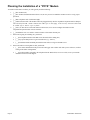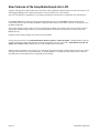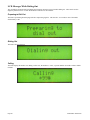
1
AcquiSuite USB Modem Addendum Applies to: A8812 AcquiSuite, A8810 AcquiSuite EMB, A7810 AcquiLite Date Nov 30, 2011 Page 1 USB Modem Addendum Copyright Information Copyright © 2001 - 2011 by Obvius Obvius and AcquiSuite are trademarks of Obvius Holdings LLc Other brand and product names are trademarks or registered trademarks of their respective holders. U.S. Government Restricted Rights: Use, duplication or disclosure by the Government is subject to restrictions set fourth in subparagraph (a) through (d) of the Commercial Computer Restricted Rights clause at FAR 52.227-19 when applicable, or subparagraph (c) (1) (ii) of the Rights in Technical Data and Computer Software clause at DFARS 252.227-7013, and in similar clauses in the NASA FAR Supplement. Limited Warranty Obvius provides this warranty for all its products in lieu of all other warranties (whether express or implied), including any implied warranty of merchantability or fitness for a particular purchase. This warranty is the buyer’s exclusive remedy for all claims against Obvius. Obvius will not be liable for any consequential or incidental damages and total liability shall be limited to the purchase price of the product. Obvius promises buyer that any product manufactured by Obvius shall be free from all material defects in material or manufacture for a period of 2 years from the date of sale. This warranty does not include ordinary wear and tear or replaceable components (e.g., batteries). During the warranty period, Obvius will repair or replace (at its sole discretion) any product shown to be defective under this warranty at no charge to buyer. Returned freight prepaid by buyer. The warranty shall remain in full force and effect for such 2 year period, provided that the product: (1) was installed, operated, and maintained properly; (2) has not been abused or misused; (3) has not been repaired, altered, or modified outside of Obvius’ authorized facilities; (4) has not been sold subject to other warranty terms specified at the time of sale; and (5) is still owned by the original purchaser. This warranty provides specific legal rights that may be varied by state law. Obvius’ products are not intended for use in critical applications such as nuclear facilities, human implantable devices or life support. Obvius is not liable, in whole or in part, for any claims or damages arising from such uses. Obvius strongly believes in continuous improvement, therefore we must reserve the right to change specifications and product offerings without notice. Where possible, we will substitute products with equivalent functionality when necessary. DANGER Hazard of Electric Shock, Explosion or Arc Flash Follow safe electrical work practices. See NFPA 70E in the USA, or applicable local codes. This equipment must only be installed and serviced by qualified electrical personnel. Read, understand and follow the instructions before installing this product. Turn off all power supplying equipment before working on or inside the equipment. Use properly rated voltage sensing device to confirm power is off. DO NOT DEPEND ON THIS PRODUCT FOR VOLTAGE INDICATION ● Only install this product on insulated conductors. Failure to follow these instructions will result in death or serious injury. ● ● ● ● NOTICE ● This product is not intended for life safety applications. ● Do not install this product in hazardous or classified locations. ● The installer is responsible for conformance to all applicable codes. FCC Part 15 Information Note: This equipment has been tested by the manufacturer and found to comply with the limits of a class A digital device, pursuant to part 15 of the FCC rules. These limits are designed to provide reasonable protection against interference when the equipment is operated in a commercial environment. This equipment generates, uses, and can radiate radio frequency energy and, if not installed and used in accordance with the instruction manual, may cause harmful interference to radio communications. Operation of this equipment in a residential area is likely to cause harmful interference in which case the user will be required to correct the interference at his own expense. Modifications of this product without the express authorization of Obvius nullify this statement. Obvius 3300 NW 211th Terrace Hillsboro, OR 97124 ph: 503-601-2099 www.obvius.com Page 2 USB Modem Addendum Table of Contents Introduction................................................................................................................................................................................................... 4 Features......................................................................................................................................................................................................... 4 Planning the Installation of a “POTS” Modem..............................................................................................................................................5 Planning the Installation of the Multitech GPRS/GSM Cellular Modem.......................................................................................................6 Comparing “POTS” Modems........................................................................................................................................................................ 7 The USRobotics USR5637...................................................................................................................................................................... 9 The Radicom-V92HU-E2...................................................................................................................................................................... 10 The TrendNET TFM-561U....................................................................................................................................................................11 Cellular Modems......................................................................................................................................................................................... 12 MultiTech MTCBA-G-U-F4 – USB GRPS cellular modem..................................................................................................................12 New Features of the AcquiSuite/AcquiLite's LCD.......................................................................................................................................14 Installation................................................................................................................................................................................................... 15 Step 1: Plug it in.................................................................................................................................................................................... 15 Note: USB Hubs............................................................................................................................................................................. 15 Step 2: Configure the Modem................................................................................................................................................................ 15 If the Modem is not found, use “USB Devices” page......................................................................................................................16 Step 3: Enable & Configure Dial-Out....................................................................................................................................................18 The Dial-Out Watchdog.................................................................................................................................................................. 18 Test Dial-Out by Running a “Connection Test”..............................................................................................................................19 LCD Messages While Dialing-Out..................................................................................................................................................20 Preparing to Dial Out................................................................................................................................................20 Dialing Out...............................................................................................................................................................20 Calling.......................................................................................................................................................................20 Modem Connecting / Waited N so far......................................................................................................................21 Modem Connected....................................................................................................................................................21 Connect failed: Modem Timeout..............................................................................................................................21 Connect failed: LINE IN USE..................................................................................................................................21 Connect failed: NO LINE or NO CARRIER............................................................................................................22 Uploading Ch N: / Sending Status............................................................................................................................22 Uploading Ch N: / Sent XX% Data..........................................................................................................................22 Uploading Ch N: / Sync Config................................................................................................................................22 Dialout Success: / Hanging up, Done.......................................................................................................................24 Upload Results: ALL OK.........................................................................................................................................24 Upload Results: X of Y fail......................................................................................................................................24 Step 4: Enable & Configure Dial-In......................................................................................................................................................25 The Dial-In Watchdog..................................................................................................................................................................... 26 Test Dial-In by Having Someone Call into the DAS.......................................................................................................................26 LCD Messages while Dialing-In......................................................................................................................................................26 Ready for Incoming Call...........................................................................................................................................26 Dial-in: Answering Call............................................................................................................................................26 Modem Connected / Receiving PPP.........................................................................................................................27 Dial-in Failed: Bad PPP User/Password...................................................................................................................27 Dial-in OK: Remote hung up!?.................................................................................................................................27 Detailed Explanation of the “Modem Setup” Options.................................................................................................................................29 The “Modem Setup” Web Page.............................................................................................................................................................29 Supported Modems..........................................................................................................................................................................29 The “Modem Setup” Page -- Options for All Modems....................................................................................................................29 The “Modem Setup” Page -- Options for GSM Cellular Modems...................................................................................................30 The “Modem Setup” Page -- Modem Diagnostics...........................................................................................................................30 Page 3 USB Modem Addendum Introduction Beginning with AcquiSuite firmware version v02.11.1106b, the AcquiSuite Data Acquisition Servers (DAS) support the following optional USB modems: • USRobotics USR5637 -- V.92 “POTS”* modem • Radicom-V92HU-E2 -- V.92 “POTS” modem • TrendNet TFM-561U – V.92 “POTS” modem (a clone of the Radicom V92HU-E2) • MultiTech MTCBA-G-U-F4 – GPRS/GSM cellular modem * “POTS” = Plain Ol' Telephone System, aka Landline Features • No modem drivers required. • USB hot-plugging fully supported. • Clear and immediate feedback is shown on the LCD of the AcquiSuite/AcquiLite during each phase of Dial-Out, Dial-In and Data-Upload to speed installation and debugging. • Installation and initial setup requires a Web Browser, but basic diagnostics are available on the LCD. • “POTS” modems support Dial-In and Dial-Out. • Cellular modems support Dial-Out only. Page 4 USB Modem Addendum Planning the Installation of a “POTS” Modem To install a USB “POTS” modem, you will typically need the following: 1. [__] The modem itself; 2. [__] The modem's documentation and drivers CD, in case you need to install the modem on a PC to verify proper operation; 3. [__] RJ11 telephone cord of sufficient length; 4. [__] USB extension cable if the modem cannot be plugged directly into the AcquiSuite/AcquiLite DAS's USB port. Note that all of the USB “POTS” modems have USB “type-A” male plugs, so the necessary extension cable would be a USB “type-A” male to “type-A” female. 5. [__] A PC (or other device with a full-featured web browser) to be used to configure the modem via the AcquiSuite/AcquiLite DAS's web user-interface. 6. [__] An Ethernet cross-over cable to connect said PC to the DAS's ethernet port. 7. If the DAS is going to be dialing out, you'll need: 8. Page 5 1. [__] The telephone number of the PPP server the DAS will be dialing into; 2. [__] Any special dial-prefixes to get an outside line (e.g., “dial 9”); 3. [__] The PPP username and PPP password the DAS will use to log into the PPP server. If the DAS will be receiving dial-in calls, you'll need: 1. [__] The contact information of the person who can trigger such a dial-in call while you are at the site, to allow testing of the dial-in configuration; 2. [__] The phone number assigned to the telephone line the DAS will use to receive calls, in case you need the assistance of Obvius Tech Support. USB Modem Addendum Planning the Installation of the Multitech GPRS/GSM Cellular Modem To install the Multitech GPRS/GSM cellular modem, you will typically need the following: 1. [__] The modem itself; 2. [__] The modem's documentation and drivers CD, in case you need to install the modem on your PC to verify proper operation; 3. [__] USB cable to connect the modem to the AcquiSuite/AcquiLite DAS's USB port. Note that all of the USB cellular modems mentioned in this document have USB “type-B” male plugs, so the necessary extension cable would be a USB “type-A” male to “type-B” male. 4. [__] A PC (or other device with a full-featured web-browser) to be used to configure the modem via the AcquiSuite/AcquiLite DAS's web user-interface. 5. [__] An Ethernet cross-over cable to connect said PC to the DAS's ethernet port. 6. [__] For GSM/GPRS modems, an appropriate SIM card, activated for the modem. 7. 1. Note: SIM cards from personal cell phones may not work with data-only cellular modems. Ask your cellular carrier about a data-plan account which is compatible with the specific Multitech Modem you plan to use. 2. Obvius strongly recommends that you verify the combination of the modem and SIM card are activated and working properly before heading out to the field. [__] Check that your data-plan limits match your intended usage with the DAS to avoid overage charges. 1. Note: Obvius recommends an unlimited data-plan. 2. Choosing an appropriate plan is your responsibility. Obvius is not responsible for any overage fees or penalties that result from choosing an insufficient data-plan. 8. [__] The carrier-specific Modem Setup (if any) string needed to initialize the modem. 9. [__] The carrier-specific Access Point Name (APN), Account username and Account password. 10. [__] Proper mounting hardware (screws, etc.) to mount the modem with the antenna positioned for optimal signal strength. Page 6 USB Modem Addendum Comparing “POTS” Modems The 3 new POTS modems are pictured on the next page, with close-ups on the following pages. Compared to the built-in modems of the AcquiSuite A8812, these USB modems each lack speakers and each have a different set of status LEDs (or in the case of the Radicom have no speaker and NO LEDs.) To compensate for this lack, the AcquiSuite and AcquiLite DAS displays status messages on its 2x16 LCD display during all phases of: • Hot-plugging, • Dial-in, • Dial-out, • Data uploading. Examples of the LCD messages are given later in this document. Page 7 USB Modem Addendum Illustration 1: Comparing "POTS" modems: USRobotics, TrendNET, Radicom Page 8 USB Modem Addendum The USRobotics USR5637 • Power LED – on when modem is receiving power from the USB port. • Data LED – blinks when modem is connected and transferring data to the remote modem. • No speaker Page 9 USB Modem Addendum The Radicom-V92HU-E2 • No LEDs whatsoever. • No speaker. Page 10 USB Modem Addendum The TrendNET TFM-561U • A “clone” of the Radicom-V92HU-E2, but with LEDs. • Link LED – on when the modem has “connected” to the remote modem. • Data LED – blinks when data sent/received to the remote modem. • No speaker. Page 11 USB Modem Addendum Cellular Modems In addition to the onboard cellular-modem options of the A8812 model, the AcquiSuite/AcquiLite DAS support the following USB cellular modems: • MultiTech MTCBA-G-U-F4 – GPRS/GSM cellular modem MultiTech MTCBA-G-U-F4 – USB GRPS cellular modem This modem is pictured below, showing the mounting bracket provided by Multitech: Page 12 USB Modem Addendum Here is a close-up of the Mulitech's front-panel showing the LEDs and slot for GSM SIM card: Page 13 USB Modem Addendum New Features of the AcquiSuite/AcquiLite's LCD Together with support for USB modems, the LCD console of the AcquiSuite/AcquiLite DAS has several new features to aid in debugging and diagnostics of dial-up connections if a PC and web-browser is not available. The new LCD behavior is intended to be very intuitive and simple, but for the sake of completeness it is described here. First, status events from the dial-out, dial-in and the data-upload processes will preempt the DAS's normal message rotation, unless the user pressed either the MENU or SELECT button in the last 3 seconds, or the user is currently in one of the DAS's LCD menus. These status messages remain on the LCD for 30 seconds, then (assuming no new status event occurs), the DAS returns to displaying its normal message rotation (e.g. showing its IP address, the timezone and current time, and any errors from Modbus devices). Examples of these status messages are given later in this document. Second, at any time the user may HOLD DOWN the SELECT button to “hold” the display. Holding SELECT stops the normal LCD message rotation and stops the LCD being preempted by any new status events. While SELECT is held, the display also scrolls at a slower rate to allow for easier reading of the LCD message. Third, the most recent status event (if there is one) will appear in the normal message rotation, and the user can review these messages in the normal way (by pressing SELECT to step through them). Typically, the status message will be either the last modem error, the last upload error or an upload success message. Page 14 USB Modem Addendum Installation Step 1: Plug it in To begin “installing” a USB modem, plug it into the AcquiSuite or AcquiLite DAS's USB port. No modem drivers are needed, and the AcquiSuite/AcquiLite DAS fully supports hot-plugging of USB devices. When the AcquiSuite/AcquiLite DAS detects the modem, it should display a message on its LCD, similar to this: The actual message may vary a bit because the description (“USB Modem”) is loaded from the USB modem itself. Note: USB Hubs Obvius recommends against using USB hubs if they can be avoided, as they add another point-of-failure to the system. Step 2: Configure the Modem For this and the following steps you must use a PC to browse to the web “user-interface” of the AcquiSuite or AcquiLite DAS. The DAS's current IP address is shown on its LCD, and can be changed via the LCD menu. (Exact details of how to do this are covered in the DAS' Installation Manual.) To setup the modem, browse to the DAS's “Modem Setup” page, which should appear as follows: If the modem type doesn't match the modem you connected, press “Scan for New Modem”, confirm that the modem found is correct, and press “Apply”. This action tells the AcquiSuite/AcquiLite DAS what modem it should expect to use. Page 15 USB Modem Addendum Note: If dial-in or dial-out is enabled but the DAS does not find a modem of the expected type or the modem fails to initialize, the DAS will report this inconsistency as an error on its LCD and in its web administration pages, and continue trying to detect and initialize the modem. If this error condition persists for an entire day (24 hours), the DAS will gracefully reboot itself in a “last-ditch” attempt to fix any possible communication problem with the modem. This should never occur in any normal operation or configuration scenario. If any special Modem Setup string is needed, enter it here and press “Apply.” Most “POTS” modems do not require any special setup string. If the Modem is not found, use “USB Devices” page If “Scan for New Modem” did not find the modem of the expected type, use the DAS's “USB Devices” page to verify the modem is connected and “seen by” the DAS. Here is an example of how the Radicom and TrendNET modems appear in the DAS's USB Devices page – unfortunately, the brand and model number on the case is often different than the details available to the DAS via USB. This example shows the MultiTech MTCBA-G-U-F4 GSM/GPRS modem as it appears in the USB Devices page: If the modem does not appear in “USB Devices”, connect the modem to a PC and follow the modem vendor's instructions to verify proper operation. If the modem appears in the “USB Devices” list, but is not assigned a Port beginning with “ttyUSB...” or “ttyACM...”, this means the DAS could not properly initialize the USB modem hardware. Typical reasons for this are: 1. Page 16 The modem is defective – Connect the modem to a PC to confirm this. If the modem's vendor provides drivers and support for their modem with a PC operating system such as MacOS or Windows, please attempt to determine if the modem works properly with a PC when following the vendor's instructions. USB Modem Addendum 2. Page 17 You are using a USB hub, and possibly other USB devices, and the combination of the hub, other devices and the USB modem exceeds the total power the DAS is able to provide to its USB port. USB Modem Addendum Step 3: Enable & Configure Dial-Out If you wish the DAS to automatically dial-out to upload meter data, you must enable and configure this via the DAS's “Dialout Setup” web page: Note that the time-of-day that the DAS dials out is configured in the “Log File Data >> Upload/Setup” page. This is described in the Installation Manual for the DAS. The Dial-Out Watchdog If dial-out is enabled, the DAS will also enable a “dial-out watchdog timer”. The “dial-out watchdog timer” will cause the DAS to reboot itself if it has not succeeded in making a dial-out connection at least once in 4 days, to the point of successfully connecting to the PPP server. This feature is intended to provide extra safety for DAS's installed in remote locations which are not easily serviced, where dial-out may be the only means of communication. If the DAS goes for 4 days without making a successful PPP connection, it will execute a graceful reboot and will record this event in the system log file. If the USB modem is accidentally disconnected from the DAS or for any reason cannot be initialized, the DAS will display a status message on its LCD warning of this situation so that it can be corrected. Example: Page 18 USB Modem Addendum Test Dial-Out by Running a “Connection Test” Once you've enabled and configured dial-out, test these settings by running a Connection Test, via the DAS's “Testing / Diags >> Connection Test” web page. The result should look something like this: Page 19 USB Modem Addendum LCD Messages While Dialing-Out The AcquiSuite/AcquiLite DAS will display the following messages on its LCD while dialing out. These can be used to diagnose problems if a PC or other full-featured web browser is not available. Preparing to Dial Out The DAS is performing housekeeping tasks like compressing log-files. This can take ~30 seconds or more if the DAS's flash-memory is full. Dialing Out The DAS is about to dial out. Calling The DAS displays the number it is dialing. In this case, the number is “*99#”, a special number used with T-mobile cellular modems. Page 20 USB Modem Addendum Modem Connecting / Waited N so far If the call takes longer than 15 seconds to connect, the DAS will remind you that it is still connecting with this message, including the total number of seconds it has waited so far. This message will update every 3 seconds. The DAS waits a total of 90 seconds to connect, then gives up. Modem Connected Assuming the modem completes the call, the DAS will display this on its LCD: Errors connecting are also indicated on the LCD: Connect failed: Modem Timeout Connect failed: LINE IN USE Page 21 USB Modem Addendum Connect failed: NO LINE or NO CARRIER The DAS now begins the process of uploading data for each of the enabled upload channels. Example messages are shown below: Uploading Ch N: / Sending Status The DAS is sending its status (system health, etc.) to the server configured for upload channel #1: Uploading Ch N: / Sent XX% Data Next the DAS sends any queued meter data for channel #1, and periodically reports the % of data it has sent so far. Uploading Ch N: / Sync Config Finally, the DAS synchronizes its configuration files with the server for channel #1. This process is covered in detail in the AcquiSuite Module Developer's Manual. For now, it is enough to know that the DAS will compare the MD5 signatures of each configuration file against those on the server, and if there are any differences it will either download or upload configuration files depending on whether the local or remote file is newer. Page 22 USB Modem Addendum The DAS will then continue on with channels 2 through 4 (if they are enabled): Page 23 USB Modem Addendum Dialout Success: / Hanging up, Done If the entire upload cycle completes, the DAS will display the following on its LCD. If the call was dropped for some reason, the DAS will display the particular modem or PPP error. Upload Results: ALL OK If all queued meter log files were upload successful on all enabled channels, the DAS will display the following: Upload Results: X of Y fail Conversely, if the DAS managed to make a modem connection (the call was answered, and PPP login was completed), but there were some errors during the upload cycle, the DAS will display a message like the following: This message shows the total number of meter data files the DAS failed to upload out of the total which were pending at the start of the upload cycle. In this example, 379 data files were pending at the start of the upload cycle, and of these, 324 data files could not be uploaded and remain in the DAS's flash memory for the next upload cycle. Note: It is normal to experience a small number of temporary upload errors especially over noisy phone lines or cellular modems with poor signal strength. The DAS displays the total number of failures rather than a percentage (%) to let you judge the severity of the problem from the LCD. Page 24 USB Modem Addendum Step 4: Enable & Configure Dial-In “Dial-in” allows the DAS to be remotely administered and allows data to be “pulled” from the DAS using Obvius' EnerTraxDL software. “Dial-in” is not supported with cellular modems. It is supported with all “POTS” modems, including all USB “POTS” modems. To enable dial-in, check the “Dialin Enabled” box in the DAS's “Dialin Setup” web page and click Apply. Like so: Within 10 to 20 seconds, the DAS's LCD should show the message “Ready for Incoming Call”, like so: If the DAS encounters problems while preparing the modem to receive incoming calls, it will display messages such as these on the LCD display. These will be updated every few minutes until the problem is corrected or “dial-in” is disabled. Page 25 USB Modem Addendum The Dial-In Watchdog If dial-in is enabled, the DAS will also enable a “dial-in watchdog timer”. The “dial-in watchdog timer” will cause the DAS to gracefully reboot itself if it fails to successfully initialize the modem to receive incoming calls at least once every 24 hours. To be clear: The DAS does not need to actually receive a call every 24 hours, it simply needs to communicate with the modem and successfully prepare to receive dial-in calls once every 24 hours. The one exception to this is if the “Remain connected after upload” option is enabled in the “Dialout Setup” page – if the DAS sees that the modem is in-use, it will ignore its “dial-in watchdog timer”. This feature is intended to provide extra safety for DAS's installed in remote locations which are not easily serviced, where dial-in may be the only means of communication. In normal operation, the “dial-in watchdog timer” should never trigger. The DAS will usually initialize the modem and begin listening for an incoming call within 10 seconds of the modem hanging up from a previous call, and the DAS will reinitialize the modem to receive incoming calls once every hour for safety. Test Dial-In by Having Someone Call into the DAS Once “dial-in” is enabled, you should test it by having someone call the AcquiSuite/AcquiLite, connect via PPP and login using one of the 3 standard user accounts: • admin • operator • user The following messages will be shown on the AcquiSuite/AcquiLite's LCD when a call is received. LCD Messages while Dialing-In Ready for Incoming Call Indicates the DAS has initialized the modem and is ready to answer a call: Dial-in: Answering Call The DAS has detected a “ring” and is attempting to answer the call Page 26 USB Modem Addendum Modem Connected / Receiving PPP The DAS has answered the call, connected to the remote modem, and is negotiating a PPP connection Dial-in Failed: Bad PPP User/Password If the remote system fails to provide the proper username or password, the DAS will report the following on its LCD: Dial-in OK: Remote hung up!? The dial-in call ended with the remote end hanging up. This is not an error unless unexpected. Within 10 to 20 seconds, the DAS will report it is ready to receive another call. Page 27 USB Modem Addendum Page 28 USB Modem Addendum Detailed Explanation of the “Modem Setup” Options The “Modem Setup” Web Page This configuration option will allow you to configure specific features in the modem if needed. For most applications, the default settings are ok. The options are as follows: Scan for New Modem button: When clicked, the AcquiSuite will begin searching for the best modem to use. It first scans any USB devices and then looks for an onboard modem (on a daughtercard, A8812 only). While the scan is in progress, a message is displayed. This scan usually takes around 5 seconds but can take up to 60 seconds with certain USB cellular modems because the modem must register itself with the cellular network after being powered on. Modem type: This shows the type modem detected, or "No-Modem" if none was detected or the modem was not recognized as a supported modem. Supported Modems Vendor Model # Description dial-up (POTS) modems Multitech MT3400SMI dial-up modem, daughtercard, A8812 only Multitech MT5600SMI dial-up modem, daughtercard, A8812 only Multitech MT5656SMI dial-up modem, daughtercard, A8812 only Multitech MT5692SMI dial-up modem, daughtercard, A8812 only U.S.Robotics USR5637 dial-up modem, USB version Radicom V92HU-E2 dial-up modem, USB version GSM cellular modems Multitech MTSMC-G GSM cellular modem, daughtercard, A8812 only Multitech MTCBA-G-U-F4 GSM cellular modem, USB version; Note: will appear as "MTSMC-G, connected via USB" The “Modem Setup” Page -- Options for All Modems Max serial port speed: This feature allows you to specify the maximum speed at which th modem can communicate at. The default is 115.2kbps. This is useful in diagnosing noisy phone lines, you may be able to get a more reliable connection by slowing down the maximum rate of data transfer. Setup string: This option allows the use of specialized modem setup strings. The default "AT" is sufficient for most applications. Modem speaker enabled: This option sets whether the speaker is on or off. The older AcquiSuite A8811-1 (rev C) does not contain a speaker. Newer models manufactured after September 2005 include a modem speaker. (Dialup modems only). Debug PPP messages: Checking this option will allow the system debug log to show a complete report of the PPP connection status. This will include the PPP session negotiation for an IP address and other connection parameters. You must click the "start log" button on the system/log files page to record this information. Debug modem chat: Checking this option will record information about the modem setup and call summary. This includes modem line quality and setup parameters. You must click the "start log" button on the system/log files page to record this information. PPP MTU: MTU, or Maximum Transfer Unit, allows reducing the maximum size of IP packets sent over dialup/PPP connections. This option should only be changed under the direction of Tech Support. Modem Diagnostics: This button will run a diagnostic test on the modem to verify that it is working and report the modem firmware version number. Page 29 USB Modem Addendum The “Modem Setup” Page -- Options for GSM Cellular Modems GSM band: Lets you select the GSM frequency band. GSM signal strength: Displays the most recent signal strength reported by the modem. GSM signal quality: Displays the most recent signal quality reported by the modem. The “Modem Setup” Page -- Modem Diagnostics This page displays detailed information about the modem such as its model code, firmware version (for some modems) and supported features. The format varies because the information comes directly from the modem in the vendor's format. Reset Modem: This button will issue a command to reset the modem. Page 30 USB Modem Addendum