1
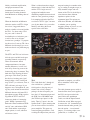
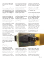
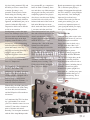
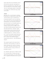
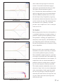
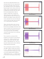
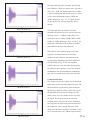
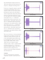
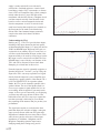
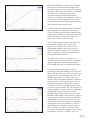
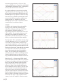
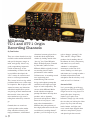
Millennia
TD-1 and STT-1 Origin
Recording Channels
By Tom Bowlus
There was a time when the bass rigs
available on the market had definite
and specific frequency ranges in
mind, and typically weren’t very
good at reproducing frequencies
outside of that range. As the
understanding of electric bass and
its possibilities developed, the
“bass” came to be seen more and
more as a full-range instrument.
This, in turn, led to bass rigs which
performed better over a wider range
of frequencies. But for players who
wanted to remove any limitations
which their amplification system
was placing on their instrument and
their musical vision, most of the
mass-market bass rigs weren’t
taking them where they wanted to
go.
Granted, there are some bassspecific products on the market
today which do offer truly fullrange performance, with minimal
32
bass
gear
coloration, but many players have
found their ideal amplification
solution by looking outside of the
“bass rig” box. Enter Millennia
Music & Media Systems. Founded
by John and Cynthia La Grou,
Millennia Media originally focused
on recording classical music
performances in the northern
California area. As recording moved
on to engineering and
manufacturing, John set out to
design a microphone preamp that
could deliver the highest possible
degree of sonic transparency. The
success which Millennia Media
found with their microphone
preamps led them to develop other
products, such as dynamics
processors and equalizers. What’s
better for us bass players – and
many other instrumentalists –
Millennia has packaged many of
these high-performance circuits into
two different “recording channel”
products (you’ll be forgiven if you
refer to them as “preamps”), the
TD-1 and STT-1 Origin. These
products aim for nothing short of
the ultimate in clarity, transparency
and control over your source,
whether it’s a microphone,
instrument, or other line level
source. Reading over their specs
and feature sets is enough to make a
die-hard tech-head drool with
anticipation. But how do they really
work on bass? Let’s find out...
One and a Half
Let’s get one thing out of the way
right up front. The TD-1 and STT-1
Origin are not for every player. For
some folks, those “frequency
limited” rigs I spoke of are
hallowed, vintage rigs with exactly
the voice they are looking for. Other
players shy away from too many
knobs, buttons, and lights, and
crave a much more stripped-down
and basic setup. But for players
who place high value on sonic
fidelity, uncolored amplification,
and proper treatment of the
instrument signal from start to
finish, these recording channels
from Millennia are nothing short of
amazing.
When the kind folks at Millennia
offered to send us an STT-1 Origin
for review, I suggested that we
make it a double review and include
the TD-1. I’ve been using a TD-1
for years, and it’s been an
invaluable piece of reference gear –
as well as one of my all-time
favorite bass “preamps.” To prepare
for this review, I sent my TD-1 in to
Millennia for a thorough go-over to
make sure that it was performing up
to spec.
The STT-1 and TD-1 are laid out as
full rack-space and half rack-space
recording channels, respectively.
There are numerous shared
components/features, but some
notable differences, as well. Let’s
start off by discussing some of the
features they have in common. They
both offer Twin Topology® initial
gain stages. This means you have
the choice of routing your signal
through either a class-A tube gain
stage (12AT7), or a discrete, class-A
FET solid state gain stage. If you
happen to use a microphone in your
rig, they each include the renowned
Millennia discrete solid state HV-3
microphone preamp. With regard to
EQ, both the STT-1 and TD-1
feature two bands of “masteringgrade” NSEQ-2 parametric EQ.
Both units feature unbalanced XLR
and 1/4” outs, and balanced XLR
outs. Each unit has some unique
output options, as well, which we
will discuss, below.
What is evident from these shared
characteristics is that both the TD-1
and the STT-1 Origin are wellequipped to handle the most
demanding amplification needs and
make for some great bass preamps.
It is tempting to think of the TD-1
as a kind of “STT-1 light,” but once
you dig into them a bit, you realize
that they each bring their own
special tricks to the table.
amp and routing it to another entire
rig, or sending it straight to tape (er,
disk). Another unique and cool
feature of the TD-1 is the ability to
select between three different
impedance options for the
instrument input. The options are
470k ohm, 2M ohm, and 10M ohm,
so whether you are packing
magnetic pickups or piezos, or even
a MIDI instrument (such as a
TD-1
This “little black box” (though it’s
also available in a “platinum”
finish) packs a dizzying array of
features into a fairly compact
package. On the front panel, you
have the 1/4” Instrument input and
the XLR Line + REAMP® input
(the XLR mic pre input is on the
back). That 1/4” input is also the
Speaker Soak™ input, meaning that
you can insert a direct feed from a
power amplifier. This opens up
some intriguing possibilities, such
as taking the output from your tube
keyboard or sampler), you will be
able to match the correct input
impedance.
The +48v phantom power switch is
located on the front, but it applies to
the HV-3 mic input on the back
panel. Below this pushbutton
switch, we find the Input Ground
Lift/Isolate switch. When engaged,
it removes the 1/4” instrument input
from the internal audio ground (you
have the option – via an internal
jumper – of selecting either a true
ground lift, or “isolation” via
bass
gear
33
resistive and capacitive coupling).
One feature which seems
superfluous up until you need it,
and invaluable after you eventually
do need it, is the Polarity Reverse
switch. Moving down, we find a
nifty green button which enables the
Speaker Soak function (don’t plug
your amplifier output into that 1/4”
jack unless that green button is lit
up, or else bad things may happen).
At the bottom of this “row” is the
Gain control. It is labeled as both
+45 and +65, which means that the
potentiometer is capable of adding
up to 65dB gain for the mic input,
and up to 45dB gain for the
instrument and line inputs.
Now, we move on to the incredible
parametric EQ section. Both
channels have their own “In”
pushbutton which takes that band in
or out of the circuit path. There is
also a “global” EQ In switch. The
LF EQ band offers a choice of
frequency centers from 20Hz to
34 bass
gear
2.5kHz. The frequency selection
knob goes from 20 to 250, and the
X10 button predictably bumps the
selected frequency up by a factor of
10 (with the total range covering
20Hz to 2.5kHz). The two
gloriously big knobs let you dial in
15dB of boost or cut per band. The
variable Q control is extremely
useful. This allows you to adjust
how narrowly, or how broadly, the
EQ boost or cut will be applied,
relative to the selected frequency
center.
The far right-hand row of lights and
buttons features three LEDs, which
indicate that the power is on, show
when a nominal signal is present,
and show when the signal at the
balanced line level has exceeded
+26dBu (maximum output is
+32dBu). Below this, we have the
previously mentioned EQ In
control, the Twin Topology switch,
which lets you choose between the
tube or solid state topologies, and
an Input Select switch, which
selects between the Instrument and
the Line/Mic inputs. Finally, we
have a -20dB Pad switch, which
attenuates all inputs.
Switching to the rear panel, the TD1 features a nifty combined plastic
housing which contains the IEC
power receptacle, the main fuses,
and the power on/off switch. The
Earth Lift button affects the internal
audio and power ground paths. The
earth-to-chassis ground bond,
however, is never compromised.
The “REAMP I” and “REAMP II”
1/4” outputs are designed to
emulate the output characteristics of
Stratocaster® style single-coil
pickups, and/or Les Paul® style
dual-coil humbucking pickups,
respectively. Millennia is working
on other bass-specific emulation
transformers (for Jazz Bass and
Precision Bass, and possibly
others), but the REAMP Type II
should work fairly well for bass
guitar.
If you want outputs, the TD-1’s got
‘em for ya! It offers both 1/4” and
XLR balanced main outputs, as well
as 1/4” and XLR unbalanced main
outputs. The “BAL XFMR OUT” is
the XLR output from the DIdedicated transformer, which
provides a mic-level output and
features its own ground lift toggle
switch. Above this is the 1/4” Direct
Out, which is taken directly from
the TD-1’s input – before either the
tube or solid state impedance
buffers, so plugging into this output
may impact input impedance.
Finally, we have a dedicated 1/4”
mono Phones Out, which has been
optimized for use with Sennheiser
model HD-600 headphones. Output
level to the Phones Out is provided
via a “20-turn” potentiometer. The
beauty of having all of these outputs
is that they all function
simultaneously, so the output
connection possibilities are endless
(or close enough to it). The HV-3
Mic In seems innocent enough, and
is practically hidden on the back
panel, but this is a world-class mic
pre, and a major feature of the
TD-1.
STT-1 Origin
The STT-1 Origin is a no-holdsbarred, full-size 2U recording
channel. “Feature-rich” doesn’t
begin to describe the STT-1. Let’s
check out the front panel.
Beginning at the top left corner, we
have the switch for selecting the
vacuum tube (VT) or solid state
(SS) front-end gain stage, followed
by the phantom power and polarity
reverse switch. Then we get to the
“XFMR IN” switch, which is an
awesome feature that is especially
well-suited to electric bass.
Selecting this switch sends the
signal through the MIT-01 audio
path transformer, which provides a
rich, full, pleasing, tube-like
coloration. If you want your tone to
be as pristine as possible, you’ll
want to skip this feature, but I found
the impact of the MIT-01
transformer to be very musical and
“exciting,” and I think a lot of bass
players will dig it.
gain controls are provided for the
tube and solid state gain stages. The
tube gain control offers an 18dB
range, while the solid state gain
control offers a massive 40dB
range. Beneath these controls is the
1/4” instrument input.
A three-position knob selects
between the MIC, LINE, or INST
inputs. The STT-1 does not have the
option of three different input
impedances for the instrument
input, like the TD-1, but instead,
uses a fixed impedance of just over
1M ohm. The mic input has an
The STT-1 Origin offers four bands
of parametric EQ, with the middle
two bands being substantially
similar to the LF and HF controls of
the TD-1 (although on the Origin,
they bear the labels “LM” and
“HM,” and the frequency ranges are
slightly tweaked). The LF control
on the STT-1 offers the choice of
either low-frequency shelving at
6dB per octave, or else peaking,
with a fixed Q of 1.0. Six frequency
options are provided, 20Hz, 34Hz,
56Hz, 100Hz, 180Hz, or 270Hz.
The HF control also offers the
shelving/peaking option, with
frequency selection options of
impedance of just over 6M ohm,
and the line input impedance is just
over 2M ohm. The STT-1 employs a
red LED for the Overload Indicator,
and it begins to glow when the
signal is about + 18dBu, and goes
solid red at +24dBu. Separate input
4.8kHz, 5.8kHz, 8.0kHz, 10kHz,
16kHz, or 21kHz. All four bands
may be independently switched in
or out, and a global EQ in/out
switch is also provided.
In addition to offering the user the
choice of either tube or solid state
bass
gear
35
front-end gain stages, the STT-1
also offers the choice Twin
Topology with regard to the EQ and
compressor. When the EQ/COMP
TT switch is engaged, both the EQ
and compressor is provided via a
class-A solid state FET amplifier.
When the switch is disengaged, EQ
and compression is provided via
vacuum tubes (also class-A).
Moving on, we find a full-featured
compressor, with controls for
threshold, attack time, release time,
and ratio control. Anyone who has
experience with a stand-alone,
studio-grade compressor will be
right at home. In addition, the STT1 provides the Flip Dynamics
switch, which places the dynamics
section either before, or after the
EQ section. A De-Esser is also
provided, for filtering of certain
“sibilant” frequencies. This tool can
be especially useful on vocals, but I
couldn’t hear much of a difference
when using it on electric bass.
analog meter, and has a fine-tune
control for setting the zero point.
The last row of buttons includes the
COMP + LIM in/out switch, the
Output Mute in/out switch (which
mutes all Main Outputs, but does
not affect the Direct Output), and
the Meter GR switch. When this
switch is “on,” the VU meter
indicates the amount of dynamics
gain reduction. When it is off, the
VU meter tracks the output of the
balanced main outputs (note: a
meter reading of “0” is equivalent to
a balanced output level of +4dBu).
The Output Master control offers up
to +10dB when set fully clockwise,
and -16dB when turned fully
counter-clockwise. The VU meter
itself is big and proud, and just
looks so darned cool! It’s a true
The Millennia Experience
There can be no doubting that the
Millennia TD-1 and STT-1 Origin
are top-flight, high-quality units.
The feature sets speak for
themselves, and may put more than
a few jaws on the floor, all on their
own. While lightweight bass heads
are all the rage, there remains a
certain expectation that the really
high-end gear is going to have some
weight. This may be an irrational
bias; I can’t really say. But solid
chassis, big capacitors and quality
transformers do add up on the
weight scale, and I will admit to
experiencing a certain subconscious
connotation between weight and
quality – especially in regard to
36 bass
gear
The back panel of the STT-1 seems
luxuriously spacious when
compared to the TD-1, but packs
plenty of options. The IEC power
receptacle and main fuses are
similar, but there’s no power switch
(it’s on the front), and the STT-1
has a unique ground lift jumper,
instead of the little red button on the
TD-1. Like the TD-1, the STT-1 has
the XLR microphone input on the
back panel, but it also places and
XLR and TRS 1/4” line inputs right
next to the mic input. The XLR
Direct Out is a balanced copy of the
front-end input. Unbalanced XLR
and 1/4” Main Out jacks are also
provided, as is a balanced XLR
Main Out. The RCA-style jack
labeled Dynamics Link connects to
the dynamics side chain circuit, and
is used to link two STT-1 units
together for stereo operation.
preamps, DI’s, EQ’s and dynamics
processors. Both the TD-1 and the
STT-1 have a very satisfying – even
surprising, in the case of the TD-1 –
heft to them, which I love. The
thick, black faceplates and sturdy,
illuminated buttons add to the
quality feel, but those knobs really
steal the show. They are easy to get
your hand on them (which,
unfortunately, is not always the case
with gear sporting more than a
couple of knobs), and have great
tactile feedback. The larger EQ
boost/cut and Master Output knobs
border on decadence, and facilitate
the kind of fine-tuning control
you’d expect in a recording studio
control room.
These Millennia units pretty much
tick off all the boxes that a
discriminating player may be
looking for in a high-end
preamp/DI/recording channel. But
the ultimate question is, “How do
they sound?” That is not an easy
question to answer, because of the
incredible range of tone-shaping
options provided. Consider the
choice of solid state or tube frontend gain stages. The solid state FET
option is characterized by a solid,
full tone. The vacuum tube option
definitely adds more harmonic
“excitement,” but remains
controlled. No matter which
topology route you choose to
follow, the baseline tone feels very
true to the instrument, and words
like “uncolored” and “pristine” are
both unavoidable and highly
appropriate.
If you do need to tweak your tone,
though, the EQ is amazing. I’m a
big fan of truly parametric EQ, and
the ability to choose a more broad
or narrow Q setting is very
powerful. I tend to prefer a more
broad setting for boosting, and a
more narrow filter when cutting, but
you may have an entirely different
approach, and Millennia puts you in
control of what their EQ can do.
Frequencies which can be difficult
to dial in on some bass
heads/preamps (such as the upper
bass to low midrange region) are a
breeze to master with Millennia EQ.
The extended range on the high
frequency controls allows you to
dial out hiss, without diminishing
desired frequencies. Despite the raw
power and control of the EQ, I
noticed that when the global EQ is
engaged, and you take the
individual EQ filters in/out, there is
no perceivable tone difference,
provided that the boost/cut knob is
set to “0.” Impressive!
The impedance selection options on
the TD-1 didn’t make a big
difference for me when I was using
a passive Jazz Bass, but with my
old Kay upright – equipped with a
Barbera bridge pickup system
featuring eight piezo elements – it
made for some real differences.
With the Kay, the 10M setting had
the most full tone, the 470k setting
was more thin, but well-defined,
and the 2M option fell somewhere
in between.
bass preamp/DI, so a comparison
had to be made. Ultimately, these
two units have very different target
design goals, but they each offer a
compelling option to bass players
who obsess over their tone. Dialing
in what I felt to be a fairly wellbalanced and musical bass tone on
both units, Monique was more
thick, warm and round, and the TD1 was more articulate and clear.
These distinctions held true in both
tube and solid state topologies, but
when I switched to the STT-1,
engaging the transformer definitely
made the STT-1 sound more
“Monique-like.” One of the more
Spartan, but solid and truesounding, preamps I’ve used for
years and years is the Stewart UDP1a. Compared to the Stewart, the
TD-1 (set totally flat) had similar
tone balance and overall
“evenness,” but the TD-1 was
decidedly more “exciting.” The
UDP-1a does do the “un-hyped
thing” very well, though.
Based upon numerous gigs with the
TD-1, and time spent playing a
number of instruments through both
the TD-1 and STT-1 (using multiple
amps and cabs), I was thoroughly
impressed in each and every
scenario. These units just flat-out
sound great, and they give you
control over important aspects of
your signal path which you simply
don’t get with other products.
The Bottom Line
There are many paths to take in the
pursuit of tonal nirvana. If you have
already managed to reach that
happy place, then sit back, enjoy,
and play some bass! But if you
aren’t quite there yet, or wonder if
the grass might be greener
elsewhere, I strongly suggest that
you check out what the Millennia
TD-1 or STT-1 Origin bring to the
table. These recording channels
were designed to work well with a
variety of sources, including bass of
all kinds – electric bass guitar,
acoustic bass guitar, upright bass,
bass synth, etc – and they may open
up tonal possibilities that you’ve
previously been missing. This is
quality gear that will last you a
lifetime.
As I mentioned, the TD-1 has been
my “gold standard” for several
years. It is about the same size as an
Avalon U5, but offers a lot more in
terms of features and control.
Recently, I’ve been quite enamored
with the Jules Amps Monique tube
bass
gear
37
test
bass
gear
Millennia
STT-1
ENCLOSURE
Material:
Dimensions:
Weight:
Rackable:
16 gauge steel chasis
19" W x 3.5" H x 15.5" D
25 lbs
Yes
PREAMP
Inputs:
Mode:
Tubes:
Input Impedance:
EQ Type/Features:
Compressor/Limiter:
Output:
Effects Loop:
Dedicated Tuner Out:
Construction:
Additional Features:
1x1/4" Instrument Input (front panel); 1xXLR Mic In (back
panel); 1xXLR Line In (back panel); 1x1/4" Line In (back panel)
Tube/Solid State
1x12AT7 (Instrument DI); 1x12AX7 and 1x12AU7 (Input
Amplifiers); 1x12AX7 and 1x12AU7 (EQ and Dynamics
Amplifiers)
>1 MegOhm
Low selectable between 20, 34, 56, 100, 180, 270Hz (Peak or
Shelf selectable); Low Mid Parametric selectable between
either 20Hz to 220Hz or 200Hz to 2.2kHz, Q0.4-4.0
sweepable, +/- 15 dB (21 step detent); Hi Mid Parametric
selectable between either 250Hz to 2.5kHz or 2.5kHz to
25kHz, Q0.4-4.0 sweepable, +/- 15 dB (21 step detent); Hi
selectable between 4.8, 5.8, 8.0, 10, 16, 21kHz (Peak or Shelf
selectable)
Optical - Threshold (range of 40 dB Continuously Adjustable);
Attack (range of 2 mS to 100 mS, Continuously Adjustable);
Release (range of 20 mS to 3.0 S, Continuously Adjustable);
Compression Ratio (range 1.4:1 to 30:1 Continuously
Adjustable)
1 x XLR Balanced Out; 1 x XLR Unbalanced Out; 1 x 1/4"
Unbalanced Out; 1xXLR Direct Out
No
No
PCB
Switch to select between Tube and Solid State; 48V Phantom
power;Polarity Reverse switch;Transformer In/Out Switch; EQ
Bypass Switch; Each EQ Band Independently Bypassable;
Switch to select between Tube and Solid State for EQ and
Dynamics stages; Switch to place Dynamics either Post EQ or
Pre-EQ
POWER AMP
Mode:
Tubes:
Outputs:
Impedance Options:
Power Supply/Transformer:
Cooling System:
Line Voltage Options:
N/A
N/A
N/A
N/A
Analog
N/A
100VAC to 240VAC, 50/60Hz, selectable
GENERAL
Company:
Millennia Music & Media Systems
4600 Missouri Flat Road
Placerville, CA 95667
www.mil-media.com
Country of origin:
Year of origin:
Warranty:
List price:
Street price:
Price as tested:
Options:
Accessories:
Available colors:
USA
2012
1-year
$3,409.00
$3,067.99
$3,067.99
None
None
Black/Platinum
Acquired from:
Dates:
Locales:
Test gear:
Millennia Music & Media Systems
February-April 2013
Ohio
Bergantino HD212, fEARful 15/6/1, AudioKinesis TC115AF, Crest CA9, GK MB
Fusion, Markbass Big Bang, '40s Kay upright with Barbera bridge,
Sadowsky P/J 5, Squire by Fender '62 Jazz Reissue, Blast Cult One4Five,
Jules Amps Monique, Stewart UDP-1a
TEST RESULTS
1-5 (unacceptable to impeccable)
On-Bench
In-Hand
Features:
Tonal Flexibility:
Ease of Use:
Aesthetics:
Tone:
Value:
5
5
3.5
4
5
3
Internal Parts
External Parts
Overall Assembly
Ease of Repair
Instructions/Manual
Quality Per Price
In-Hand Score
average
4.25
On-Bench Score
4.21 average
SONIC PROFILE:
Lows: Full, tight, controlled
Mids: Huge range of midrange tones available
Highs: Tons of control available; very musical and rich
TONE-O-METER
Much like the TD-1, the STT-1 can cover a
huge range of tones. Once again, the
baseline tone is uncolored, well-balanced,
pure and musical. Transformer option
makes it more "tube amp like."
4.75
4.50
4.50
3.50
4.00
4.00
Tom Lees’
AMP LAB
Fig. 1 Gut shot, STT-1
Millennia STT-1
Okay, I will admit a small addiction of
mine. I have been phasing out my CD
collection in favor of songs loaded into my
iTunes® library. Because I respect the
artists that create this music... and our
copyright laws… I purchase all of my
music (as you should, too). However, I
cannot afford to purchase every album by
every artist that I want. So, I have become
addicted to the “greatest hits” album
purchases. Yup. Journey, Tom Petty,
Eagles, Bruce Springsteen up to the Foo
Fighters, the greatest hits define the
playlists of my iTunes library. So, when
offered a chance to take a look at the
Millennia STT-1, I could not pass it up.
The STT-1 Origin represents input stage
FIG. 2 SST-1 Block diagram
circuitry, equalization, compression and debass
gear
39
essing from Millennia’s very best designs, thus
presenting a Millennia “greatest hits” of processing.
We always kick things off with a gratuitous “gut
shot,” which is illustrated as Fig. 1. Here, the STT-1
does not disappoint. The power supply is neatly
tucked off to one side and is enclosed in a ventilated
enclosure. A main circuit board hosts five vacuum
tubes (a mix of JJ brand 12AX7 and 12AT7 tubes),
large custom-branded capacitors (the white tubes
FIG. 3 EQ and Compression bypassed
with the Millennia label), discrete class-A FET
servo amplifiers (those large yellow rectangles), a
daughter circuit card that extends vertically from the
center of the main circuit board, as well as various
integrated circuits and discrete components. A series
of vertical circuit cards host circuitry that couple the
user controls on the front panel to the main circuit
board using ribbon cable. Panel-mounted output
connectors couple to the main circuit board via
Molex connectors.
FIG. 4 Gain comparison solid state and tube with and without transformer
Understanding the STT-1 Origin
Refering to Fig. 2, the STT-1 provides a singlechannel input that is selectable by a control on the
front panel that selects among three inputs,
including a Mic input, a Line input and an
Instrument DI input. The Instrument DI input is
processed by a dedicated tube circuit based around a
12AT7 vacuum tube positioned before the input
selector. The Mic input and Line input are passed
directly to the input selector.
FIG. 5 THD+N ratio vs measured level
The selected input source is passed through a
polarity reversal circuit to a bypassable transformer
stage. The transformer stage passes the signal
through a custom Millennia transformer providing
electrical isolation to the signal. Moreover, at higher
signal levels, the sonic character of the transformer
can be used to apply “color” to the input.
gear
40 bass
FIG. 6 Low band
It is not new to the bass community to see bass
amps with a choice of either tube or solid state
stages. However, the STT-1 takes this concept a step
further. The user has the option to select a tube or
solid state input stage independent of a tube or solid
state equalization stage. In this regard, solid state
and tube topologies, with or without transformer
coupling, can be mixed and matched as desired.
FIG. 7 Low band
More particularly, the signal couples from the
bypassable transformer stage to a switch that selects
either a solid state input stage or a vacuum tube
input stage. The solid state and tube circuits each
have independent input gain trim controls. The
signal from the user-selected input stage flows
through a solid state amplifier to a Direct Out. The
signal from the user-selected input amplifier also
couples to a bypassable equalization stage.
FIG. 8 Low-mid band
Within the equalization stage, a four-band
parametric equalizer is provided, which is driven by
a user-selected solid state amplifier or a tube
amplifier. A dynamics stage, including a compressor
and de-esser, can share the same selected amplifier
(solid state or tube) as used by the equalizer stage.
The dynamics stage can alternatively function
without using the selected amplifier of the equalizer
stage. Moreover, a control on the front panel is
provided to place the dynamics stage either before
or after the equalizer stage. The compressor uses an
FIG. 9 Low-mid band
optical gain reduction shunt cell to control
compression, which can be fed from a signal taken
either pre-equalizer stage or post-equalizer stage.
The output of the equalization and dynamics stages
passes through a final amplifier to the outputs,
which provide unbalanced and balanced outputs,
and which are simultaneously available.
As such, the user can select for instance, an entirely
discrete, entirely class-A direct signal path from
FIG. 10 Low-mid band
bass
gear
41
input to output. The user can alternatively select to
inject tube processing into the signal path at the
input stage, equalization stage, or both. The user can
also select transformer or non-transformer coupling.
All-in-all, a mind-boggling number of combinations
are available with a somewhat deceivingly simple
set of controls.
Analysis
Referring to Fig. 3, my tests began by evaluating
FIG. 11 Low-mid band
the input stages. The input gain trim controls of the
solid state and tube stages are intentionally not
level/position matched. As such, to get equivalent
gains, I set the trim of the solid state amplifier fully
counterclockwise, and set the tube gain control to
about 11:00, which is were I found the signals to be
fairly well-matched in output level. I then ran
frequency response plots out to 50kHz for solid
state (with and without transformer) and tube (with
and without transformer). I measured a slightly
FIG. 12 High-mid band
extended frequency response from the tube stage,
compared to the solid stage with no transformer
(compare the black trace – solid state, to the red
trace – tube). The transformer imparted the greatest
exaggeration on the tube stage (compare the blue
trace – solid state with transformer engaged,
compared to the green trace – tube with transformer
engaged).
The stronger the signal level, the more the sonic
characteristics of the transformer are evident. For
FIG. 13 High-mid band
instance, referring to Fig. 4 and Fig. 5, the traces
are as follows: solid state (red), tube (blue), solid
state with transformer in (orange), and tube with
transformer in (green).
Fig. 4 illustrates a plot of gain as a function of input
level. At the particular test settings, gain began a
steady drop for input signals over 1 Vrms. However,
there is a gradual but measurable decrease in gain of
42
bass
gear
FIG. 14 High-mid band
about 0.5dB as the input signal level increased
towards 1 Vrms with the transformer engaged,
whereas the signal remained ruler-flat up to about
700 mVrms with the transformer bypassed.
Fig. 5 illustrates that with the transformer in, as the
input level increased in my test, the total harmonic
distortion (THD+N) remained above 0.2% across
the entire input sweep. Comparatively, bypassing
the transformer allowed the distortion to drop as low
FIG. 15 High-mid band
as 0.01% for the tube stage. This demonstrates that
the transformer is not “gimmicky,” but rather
provides a way to impart sonic “color” to the input
as the user sees fit.
The Equalizer
Before getting into the discussion of the equalizer, it
is worthwhile addressing a few simple concepts. A
parametric equalizer provides adjustability of three
filter parameters, including gain (amplification or
FIG. 16 High band
attenuation), center frequency, and bandwidth of the
gain. Depending upon the architecture and design,
the three filter parameters may be interactive or they
may be independent.
However, it really is not convenient to talk about
bandwidth of an equalizer band. Keep in mind that
we hear with logarithmic frequency sensitivity.
Thus, bandwidths at higher frequencies would have
to be larger to provide the basic same audible effect
as an equivalent bandwidth at a lower frequency. To
FIG. 17 High band
compensate for this, we describe bandwidth as a
parameter referred to a quality factor, or simply Q.
Q is the center frequency divided by bandwidth.
This formula normalizes bandwidth so that we can
discuss the “shape” of the cut or boost independent
of the center frequency. In this regard, the smaller
the value of Q, the larger (wider) the frequencies
affected by the band. Likewise, the larger the value
of Q, the smaller (more narrow) the frequencies
affected by the band.
FIG. 18 THD ratio solid state vs tube EQ in
bass
gear
43
The STT-1 boasts independent bands that can be
individually added to the circuit or bypassed from
the circuit using individual switches on the front
panel. Additionally, the STT-1 boasts independent,
highly uncoupled controls, allowing consistent and
absolute control of the applied equalization, with a
Q adjustment that varies from 4.0 to 0.4 in each of
the low-mid and high-mid bands. Moreover,
regardless of whether tube or solid state, the
equalizer stage places a single amplifier in the
FIG. 19 Scope threshold -20
signal path. Each band is built into a shunt network
about this single amplifier, such that a band, even if
actively connected to the circuit via the front panel
switch, only affects the signal if the gain control is
set to a value other than 0 (center position).
Taking a look at the equalizer, there are way too
many options to discuss in a single review. Thus,
this discussion only highlights certain features of the
equalizer. In addition to the selection between solid
FIG. 20 Scope threshold noon
state or tube gain for the equalizer stage, the user
can select up to four bands, each individually
selectable. The bands include a low low-mid, highmid and high bands.
The low band allows an extremely flexible
treatment of low end. The user can select between
shelving or bell, +/-15dB at a center that is userselectable at one of 20Hz, 34Hz, 56Hz, 100Hz,
180Hz, or 270Hz. Referring to Figs. 6 and 7, the
low band is illustrated at the extremes of 20Hz and
FIG. 21 Scope threshold 20
270Hz in both shelf and bell modes.
The low-mid band offers parametric bell filtering
from 20Hz to 220Hz at a quality factor (Q) from 4
to 0.4 at +/- 15dB. The low-mid band also includes
a x10 switch that shifts the frequency up by a factor
of 10 to allow adjustment between 200Hz and
2.2kHz. Referring to Figs. 8 - 11, equalizer plots are
provided for the extreme frequency and Q settings.
44 bass
gear
FIG. 22 Scope attack 2 ms
The high-mid band offers parametric bell filtering
from 250Hz to 2.5kHz at a quality factor (Q) from 4
to 0.4 at +/- 15dB. The high-mid band also includes
a x10 switch that shifts the frequency up by a factor
of 10 to allow adjustment between 2.5kHz and
25kHz. Referring to Figs. 12 - 15, equalizer plots
are provided for the extreme frequency and Q
settings.
FIG. 23 Scope attack at noon
The high band allows an extremely flexible
treatment of high end. The user can select between
shelving or bell, +/- 15dB at a center that is userselectable at one of 4.8kHz, 5.8kHz, 8kHz, 10kHz,
16kHz, or 21kHz. Referring to Figs. 16 and 17, the
high band is illustrated at the extremes of 4.8kHz
and 21kHz in both shelf and bell modes.
The behavior of the equalizer stage is the same,
regardless of whether the tube or solid state
FIG. 24 Scope attack 100 ms
amplifier is used. However, the character of the
signal changes depending upon which amplifier is
used. Referring to Fig. 18, the tube amplifier
exhibits relatively lower distortion when toggling
the tube/solid state equalizer switch. This could be
attributable to the fact that Millennia intentionally
does not level-match between tube and solid state.
Compressor/De-Esser
The compressor provides control over the threshold,
attack time, release time and compression ratio. The
FIG. 25 Scope release 0.02
threshold defines a point where signals below the
threshold are unaffected. Thus, signals that exceed
the threshold are treated by the compressor. The
attack is how “fast” the compressor acts to clamp
the signal. The faster the attack, the faster the
clamping action. Likewise, the release determines
how long after the signal falls below the threshold
the compressor stops working. The ratio is how
much gain reduction is applied. For instance, a ratio
of 2:1 means that for every 2dB the input increases
FIG. 26 Scope release 1
bass
gear
45
above the threshold, the output only increases by
1dB. It can be difficult to describe the behavior of a
compressor, so I thought I would simply show it.
For these tests, I engaged the compressor, turned off
each equalizer band individually and set all four
compressor controls to the center (noon) position. I
then picked one control at a time and swept that
control, leaving the others at their center positions. I
injected a test signal that included bursts of signal
FIG. 27 Scope release 3
level with enough cycles to illustrate the parameters
of the compressor. Figs. 19 - 21 illustrate the
threshold swept from fully counterclockwise, noon
and fully clockwise, with all other controls at noon.
Figs. 22 - 24 illustrate the attack swept from fully
counterclockwise, noon and fully clockwise, with all
other controls at noon. Figs. 25 - 27 illustrate the
release swept from fully counterclockwise, noon
and fully clockwise, with all other controls at noon.
Figs. 28 - 30 illustrate the ratio swept from fully
FIG. 28 Scope ratio 1.4 to 1
counterclockwise, noon and fully clockwise, with all
other controls at noon.
The de-esser uses the same --resistive gain reduction
elements used by the compressor, and can be used
simultaneously with the parametric equalizer. The
de-esser and broadband compressor/limiter cannot
be used simultaneously. The de-esser can be varied
from off, 4.9kHz, 6.8kHz, 8.2kHz, 10.7Hz or
12kHz. The de-esser is interactive with the
compressor controls, so there is a significant amount
FIG. 29 Scope ratio 6 to 1
of flexibility. Referring to Fig. 31, the de-esser is
illustrated sweeping the frequency control. Fig. 32
illustrates the effect of setting the de-esser
frequency and varying the compressor threshold to
affect the amount of cut.
Conclusion
One of my favorite things about “greatest hits”
compilations is that there is no filler stuff. True to
46 bass
gear
FIG. 30 Scope ratio 30 to 1
this concept, the STT-1 is packed full of useful,
features. The equalization section is likely the most
well-behaved, close to ideal implementations that I
have tested. The compressor is precise and welltuned. Again, likely the most well-behaved and
precise compressor that I have tested. My only
complaint about this device is that I have to let it go.
I must send it along to our Editor-in-Chief for his
in-hand review.
FIG. 31 De-esser sweep
FIG. 32 Vary compressor threshold
bass
gear
47
test
bass
gear
Millennia
TD-1
ENCLOSURE
Material:
Dimensions:
Weight:
Rackable:
16 gauge steel chasis
8.5" W x 3.5" H x 13" D
16 lbs
No
PREAMP
Inputs:
Mode:
Tubes:
Input Impedance:
EQ Type/Features:
Compressor/Limiter:
Output:
Effects Loop:
Dedicated Tuner Out:
Construction:
Additional Features:
1x1/4" Instrument Input (front panel); 1xXLR Line/Reamp
(front panel); 1xXLR Mic In (back panel)
Tube/Solid State
1 x 12AT7
User selectable between 10 Megohm; 2 Megohm and
470 kOhm
Low Mid Parametric selectable between either 20Hz to
220Hz or 200Hz to 2.2kHz, Q0.4-4.0 sweepable, +/- 15 dB (21
step detent); Hi Mid Parametric selectable between either
250Hz to 2.5kHz or 2.5kHz to 25kHz, Q0.4-4.0 sweepable,
+/- 15 dB (21 step detent);
N/A
1 x XLR Balanced Out; 1x 1/4" Balanced Output; 1 x XLR
Unbalanced Out; 1 x 1/4" Unbalanced Out; 2 x 1/4" Reamp
Outputs; 1 x1 /4" TRS Phones Out; 1 x 4 DI Out; 1 x XLR DI Out
No
No
PCB
48 V Phantom power; Input ground lift; Polarity Reverse
switch; 1/4" Input can handle speaker levels using Power
Soak feature); Three user selectable Input Impedance
Settings; EQ Bypass; Each EQ Band Independently
Bypassable; Switch to select between Tube and Solid State; 20 dB pad; Reamp Outputs (2 different outputs with different
characteristics)
GENERAL
Company:
Millennia Music & Media Systems
4600 Missouri Flat Road
Placerville, CA 95667
www.mil-media.com
Country of origin:
Year of origin:
Warranty:
List price:
Street price:
Price as tested:
Options:
Accessories:
Available colors:
USA
2005
1-year
$2,100.00
$1,889.99
$1,889.99
Top handle
Custom gig bag ($100)
Black/Platinum
Acquired from:
Dates:
Locales:
Test gear:
Tom Bowlus
February-April 2013
Ohio
Bergantino HD212, fEARful 15/6/1, AudioKinesis TC115AF, Crest CA9, GK MB
Fusion, Markbass Big Bang, '40s Kay upright with Barbera bridge,
Sadowsky P/J 5, Squire by Fender '62 Jazz Reissue, Blast Cult One4Five,
Jules Amps Monique, Stewart UDP-1a
TEST RESULTS
1-5 (unacceptable to impeccable)
On-Bench
In-Hand
Features:
Tonal Flexibility:
Ease of Use:
Aesthetics:
Tone:
Value:
5
4.5
4
4
5
3.5
Internal Parts
External Parts
Overall Assembly
Ease of Repair
Instructions/Manual
Quality Per Price
POWER AMP
Mode:
Tubes:
Outputs:
Impedance Options:
Power Supply/Transformer:
Cooling System:
Line Voltage Options:
N/A
N/A
N/A
N/A
Analog
N/A
100VAC to 240VAC, 50/60Hz, selectable
In-Hand Score
average
4.33
On-Bench Score
average
4.25
SONIC PROFILE:
Lows: Full, tight, controlled
Mids: Huge range of midrange tones available
Highs: Tons of control available; very musical and rich
TONE-O-METER
It is very hard to describe the tone of the
TD-1, because it can cover such a wide
range of tones. The baseline tone,
however, is uncolored, well-balanced,
pure and musical.
4.50
4.50
4.50
3.50
4.50
4.00
Tom Lees’
AMP LAB
Fig. 1 Gut shot, STT-1
Millennia TD-1
I will bet that most of you out there have more
than one bass, more than one amp, an extra set
of cables, and a host of other accessories.
However, when it comes to recording, we
simply rely upon the studio to furnish the
necessary equipment. When we show up at a
gig, we either settle for the DI built into the
amp, or rely on the soundman to use
“whatever” DI he has laying around. Why is
that? As much time as we spend obsessing over
the tone that we hear when performing, why do
we not better plan for the tone everyone else
hears, be it in the house system or recorded at a
studio? Better yet, once we are in the studio
and our “sound” is printed into digital media,
why do we not take every measure to carefully
recreate that sound live? Worry not folks,
because Millennia has brought us the TD-1. It
is boasted as a “Twin Direct” recording
channel. But we will see that it really is much
more than that.
FIG. 2 TD-1 Block diagram
Referring to Fig. 1, our “gut shot” illustrates
that the TD-1 crams about as much circuitry as
possible inside its shoebox chassis. The power
bass
gear
49
supply is neatly tucked off to one side and is
enclosed in a ventilated enclosure. A main circuit
board hosts a single 12AT7 vacuum tube, a discrete
class-A FET servo amplifier (large yellow rectangle
tucked under the wires, just to the right of the
transformer with the blue ribbon), a daughter circuit
card that extends vertically from the main circuit
board, as well as various integrated circuits and
discrete components. A series of vertical circuit
cards host circuitry that couple the user controls on
the front panel to the main circuit board using
ribbon cable. Panel-mounted output connectors
couple to the main circuit board via Molex
connectors.
FIG. 3 250Hz sin swept level gain control at 9 o’clock
Understanding the TD-1
Refering to Fig. 2, The TD-1 provides three inputs,
including a Mic input (located on the back panel),
an Instrument/Speaker input (1/4” input jack) and an
XLR Line/REAMP input. Right out of the gate, we
see that this is no ordinary device. For our tests, we
will focus on the Instrument DI input, as that is the
input most likely to be used by a bass player, but the
Mic input is a nice extra to have on hand. The Line/
REAMP input is one of the key cool features of the
TD-1 and will be discussed in more detail when
Reamping is revisited later in this review.
From the input, the signal is optionally coupled to a
Speaker Soak circuit. “A what?” you say? Why, the
input of the TD-1 can accept a speaker-level signal
directly from the output of a power amplifier (also
connected to a speaker cabinet). Note that the TD-1
is NOT A SUBSTITUTE for a speaker cabinet.
Rather, the TD-1 can be situated in parallel with a
speaker cabinet. The use of the Speaker Soak is a
clever way to capture a signal suitable for live use
or recording, which is tapped off your amp’s main
output. As far as you are concerned, you are playing
your bass amp with your cabinet of choice. But
behind the scenes, the TD-1 steps up to capture the
tone that your amp is delivering to your cabinet,
thus capturing all the nuances that you put into your
performance.
The signal next couples to a switch on the front
panel that allows the selection of either a tube gain
stage or an all-discrete solid state FET gain stage.
Regardless of whether the user selects tube or solid
state, the user can also select one of three input
impedances, 470 kOhms, 2 Megohms, and 10
Megohms. Depending upon the input source,
changing among these settings may provide
bass
50 gear
FIG. 4 250Hz sin THD+N level vs measured level
FIG. 5 250Hz sin swept level gain control at noon
undetectable differences, such as where the input
source has an electrically buffered output with a
low-output impedance (e.g., an active bass, playing
through an effect pedal with a buffer, etc). However,
with other sources (such as passive basses,
instruments equipped with un-buffered piezo
pickups, etc.), changing input impedance can have a
subtle to drastic affect. Regardless of input source,
you should experiment to find the input impedance
that provides the most musical result.
FIG. 6 250Hz sin swept level gain control max
A switch on the front panel determines whether the
signal is padded by a -20dB pad. After the pad
circuit, the signal passes through an amplifier with
variable-gain, adjustable by a gain knob on the front
panel and a polarity reversal circuit that can be
bypasses by a switch on the front panel.
Next, the signal passes through a dual-band, fully
programmable equalizer stage, which can be
bypassed by a switch on the front panel. The
programmable equalizer stage here is not your
typical bass amplifier equalizer. The equalizer is
precise, extremely well-behaved and predicable,
with minimal band interaction.
The output of the equalizer stage passes to an
unbalanced output, a balanced output, a headphone
output, a transformer-isolated balanced output, a
first REAMP output and a second REAMP output.
FIG. 7 Frequency sweep LF Q 0.4
FIG. 8 Frequency sweep LF Q 4
To tag back around to the input, it is worth
explaining the REAMP capability of the TD-1 a bit
further. The idea is this: a recorder sends a line-level
signal to the Line/ REAMP input of the TD-1. The
REAMP input couples to a discrete solid state
amplifier with an impedance matched for playback
of recorded bass tracks. In simple terms, the Line/
REAMP input presents a load that the recorder is
“expecting” to see, thus coupling the output of the
recorder in a precise manner. The TD-1 then uses its
internal circuitry to present a signal at the REAMP 1
and REAMP 2 outputs. The first and second
REAMP outputs provide a dual purpose. First, the
REAMP 1 and REAMP 2 outputs shift the signal to
instrument levels. Moreover, each of the REAMP 1
and REAMP 2 outputs provides distinct electrical
characteristics that can be thought of as simulating
an instrument, so that your amplifier is “tricked”
into thinking you are plugging straight in with no
effects, processors or other circuitry intervening
between the instrument and amplifier. That is, when
the amplifier “looks out,” it thinks it “sees” an
bass
gear
51
instrument plugged directly in. Thus, the TD-1
outputs an instrument-level signal from the REAMP
1 and REAMP 2 outputs that “look” to an amplifier
like they came from an actual instrument.
In a typical application, you can record your bass
signal directly into the recording system, then play
the raw track back through the REAMP input and
REAMP output to any amplifier of choice as many
times as desired, so that the recorded signal can be
processed with different equalizer settings, amps,
speaker cabinets, etc. Alternatively, the Line/
REAMP input can be used in conjunction with the
normal balanced or unbalanced outputs.
FIG. 9 Frequecy sweep LF Q 0.4 shift x 10
Analysis
A switch on the front panel selects the amplifier
topology used to buffer the Instrument input
between an all-discrete, solid state J-FET (fieldeffect transistor) DI buffer amplifier or a
high-voltage twin-triode vacuum tube (12AT7) DI
buffer amplifier. The selectable solid state or tube
gain stage is not available for the Mic or Line
inputs. Rather, the Mic and Line inputs are routed
directly to a discrete-hybrid solid-state amplifier.
The input of the TD-1 can handle an uncanny range
of signals. Referring to Figs. 3-8, I swept the level
of a 250Hz sine signal with the solid state stage
(red) and tube stage (blue). As Fig. 3 illustrates, the
gain is steady and linearly tracks the input level for
input levels up to about 5 Vrms with the gain control
set to about 9:00. After about 5 Vrms, the gain
drops, indicating that the signal is beginning to
distort. This was with the pad disengaged! It is
worth observing that for this test, the output (taken
from the balanced output) was about 30 Vrms, so
any question about headroom should be laid to rest.
Referring to Fig. 4, for that same 250Hz signal, I
also looked at the distortion (THD+N) as a function
of input level for both the solid state (red) and tube
(blue). Note that the distortion in the solid state
signal steadily declines as the input signal level
increases to about 1 Vrms. Indeed, the distortion
drops remarkably to below 0.002%. The tube stage
stays well under 1%, but the distortion begins to
increase above about 100 mVrms, illustrating the
soft tube compression that is characteristic of tubes.
Both the tube and solid state channels converge at
about 1% THD+N. This chart is deceiving. I would
not call the tube stage a “dirty” amplifier. To the
contrary, for the tube amplifier, distortion remains
52
bass
gear
FIG. 10 Frequency sweep LF Q 4 shift x10
FIG. 11 Sweep of Q
well under 1% up to 2 Vrms. Thereafter, the natural
tube compression serves as a soft limiter, thus
making even higher amounts of distortion tolerable
due to the ratio of generated harmonics (we know
this as that “warm” tube tone).
FIG. 12 Frequency sweep HF Q 0.4
Referring to Fig. 5, I cranked the input gain control
up to noon and repeated the set of output tests. As
Fig. 5 illustrates, the gain is steady and linearly
tracks the input level for input levels up to about 1
Vrms with the gain control set to about noon for
both the solid state (red) and tube (blue). Similarly,
Fig. 6 illustrates that gain is steady and linearly
tracks the input level for input levels up to about
200 mVrms with the gain control set to its
maximum clockwise position for both the solid state
(red) and tube (blue).
The Equalizer
The TD-1 features two parametric equalizer bands.
Each equalizer band includes a frequency select
control, a gain control (boost or cut) and a Q
control. Each band also includes a x10 switch that
shifts the frequency range by a factor of 10. See the
STT-1 review for an explanation of parametric
equalization. Regardless of whether one or both
bands are used, the equalization stage places only a
single amplifier in the signal path.
FIG. 13 Frequency sweep HF Q 4
Referring to Figs. 7 and 8, the low-channel
frequency sweep is illustrated at the extremes of
frequency and Q. Figs. 9 and 10 illustrate the same
settings as Figs. 7 and 8 respectively, with the x10
frequency shift engaged. Fig. 11 illustrates a single
frequency where the Q setting is swept.
Referring to Figs. 12 and 13, the high-channel
frequency sweep is illustrated at the extremes of
frequency and Q. Figs. 14 and 15 illustrate the same
settings as Figs. 12 and 13 respectively, with the
x10 frequency shift engaged. Fig. 16 illustrates a
single frequency sweeping the Q setting.
FIG. 14 Frequency sweep HF Q 0.4 shift x10
Referring to Fig. 17, with the equalizer stage flat, I
compared the solid state (red) to the tube (blue)
input. I did not attempt to level match between solid
state and tube to see the difference between the
amplifiers. At the selected settings, the solid state is
ruler-flat from about 20Hz out well past 50kHz. The
tube amplifier provided just under 1dB less gain
than the solid state amplifier. The low end is
electrically similar to the solid state amplifier.
However, the tube amplifier does not have the same
bass
gear
53
degree of linearity as the solid state amplifier when
extended out to 50kHz for the given test conditions.
Rather, the signal drops off about 2dB.
Performance
Referring to Fig. 18, I ran a test to measure the
distortion products to compare the solid state (red)
and tube (blue) amplifiers for a given input
stimulus. Both show a reasonably linear response at
+10dB, even out towards 50kHz. With regard to the
solid state channel, the second harmonic (in orange)
is slightly higher than the third harmonic (seen in
light purple). Comparatively, the second harmonic
of the tube stage (seen in green) is about 35db
stronger than the third harmonic (dark purple). The
relatively stronger emphasis of second harmonics in
the tube amplifier is consistent with the other tests
performed herein, and is a tell-tale sign of the tube
topology. This is just one of the reasons that having
both the solid state stage and the tube stage is cool.
FIG. 15 Frequency Sweep HF Q 4 shift x10
Reamping
“Active sources,” such as outputs from recording
equipment, provide an extremely low-output
impedance, compared to instruments. This
sometimes causes instrument amplifiers to sound
unusually clean. To address this, the REAMP 1 and
REAMP 2 outputs provide level matching and
impedance matching to mimic instrument pickups.
The REAMP 1 and REAMP 2 outputs provide
passive guitar-pickup emulation via John Cunibertis
patented REAMP technology (which he sold to
Radial; Millennia as a licence). More particularly,
Millennia suggests that REAMP 1 output can be
used to effectively emulate the output characteristics
of Stratocaster style single-coil pickups, whereas
REAMP 2 output can be used to effectively emulate
Les Paul style dual-coil “hum-bucking” pickups.
Both the REAMP 1 and REAMP 2 outputs can be
used simultaneously.
Referring to Fig. 19, the outputs are illustrated to
demonstrate the differences between the balanced,
unbalanced, REAMP 1 and REAMP 2 outputs. The
balanced output is in black. The unbalanced output
is in blue and mirrors the balanced output, with less
gain, as would be expected. The REAMP 1 output is
in red and exhibits a characteristic transformer
resonant peak at around 200Hz. The second
REAMP output is substantially flat to a frequency of
just over 50kHz, thus providing a different character
tone for Reamping applications.
54
bass
gear
FIG. 16 Sweep of Q
FIG. 17 Extended frequency response
bass
gear
55
Conclusion
There is a lot to like about Millennia products in
general, and the TD-1 in particular. Having a
recording tool that also provides a flexible equalizer
and gain stage that can be used live cannot be
underestimated. For instance, the TD-1 can function
as an awesome direct box, with the added bonus of
two bands of Millennia’s parametric equalization. I
am particularly fond of the three impedance options.
The use of loading presents an opportunity to shape
the sound without injecting a bunch of circuitry into
the signal path, which I find useful and completely
in line with Millennia’s mantra of keeping the signal
path clean. While it appears from my electrical tests
that the TD-1 is all about transparency, detail and
accurate representation, I would have liked to have
seen at least some feature that is intended for
“color,” such as the transformer provided on the
STT-1 Origin. Having the ability to “dirty up” the
signal is sometimes useful, especially when getting
creative, which is likely to happen if you embrace
the power of the soak and REAMP capabilities built
into the TD-1.
FIG. 18 Comparison of distortion tube and solid state
FIG. 19 Output comparison
ENTER TO WIN Stu Hamm
signature bass
visit: www.washburn.com
A Chicago Original Since 1883
Washburn Is A Division Of U.S. Music Corp. | 1000 Corporate Grove Dr. | Buffalo Grove, Il. 60089 | 800.877.6863