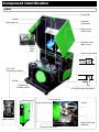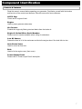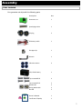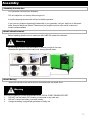
1
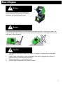
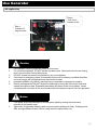
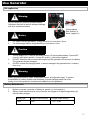
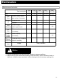
BEEM Outdoors LLC. Natural Gas & LPG
Generator Set Model # BMG5
Operation Instruction & Owner’s Manual
BEEM Outdoors LLC. MODEL NO. : BMG5
Caution:
Carefully read and understand this Owner’s Manual before starting this generator
Introduction
Introduction
Congratulations on your purchase of our generator. We design and build generators to strict
specifications. With proper use and maintenance, this generator will bring you years of satisfying
service.
Generator Set
This unit is LPG or natural gas engine driven, alternating current (AC) generator. It is designed to
supply electrical power for lighting, appliances, tools and similar equipment. Do not use gasoline or
other fuels.
This Booklet
This manual covers operation and maintenance. All information in this publication is based on the
latest product information available at the time of approval for printing. Every effort has been made
to ensure the accuracy and completeness of the information in this manual. We reserve the right to
change, alter and / or improve the products and this document at any time without prior notice and
without incurring any obligation.
Record the model and serial number as well as date and places of purchase for future reference.
Have this information available when ordering parts and when technical or warranty inquiries.
Authorized Sales & Service Distributor:
Model Number:
Engine Serial Number:
Air-Fuel Mixer Serial Number:
Date Of Purchase:
Purchase Location:
1
Manual Conventions
Manual Conventions
This manual uses the following symbols to help differentiate between different kinds of information.
The safety symbol is used with a key word to alert you to potential hazards in operating and owning
power equipment.
Following all safety messages to avoid or reduce the risk of serious injury or death.
!
Danger
Danger indicates an imminently hazardous situation which, if not avoided, will result in death or
serious injury.
!
Warning
Warning indicates a potentially hazardous situation which, if not avoided, could result in death or
serious injury.
!
Caution
Caution indicates a potentially hazardous situation which, if not avoided, may result in minor or
moderate injury.
!
Notice
Notice gives helpful information.
2
Safety Rules
!
Warning
Please read and understand this manual thoroughly before operating your generator. Failure to
follow instructions could result in serious injury even death.
!
Warning
Exhaust gas contains poisonous carbon monoxide, which is harmful to the health. Never use the
generator set at the confined places or poor ventilated locations. If it’s necessary to run the
generator set, be sure to provide the adequate ventilation.
!
Danger
Generator produces powerful voltage.
1.
DO NOT touch bare wires or receptacles.
2.
DO NOT use electrical cords that are worn, damaged or frayed.
3.
DO NOT operate generator in wet condition or with wet hand.
4.
DO NOT allow children or unqualified persons to operate or service the generator.
5.
DO NOT use a ground fault circuit interrupter (GFCI) in damp areas and areas containing
conductive material such as metal decking.
!
Warning
Use approved transfer equipment to isolate generator from your electric utility and notify your utility
company before connecting your generator to your power system.
!
Warning
Sparks can result in fire or electrical shock. When servicing the generator, disconnect the spark
plug wire and place it where it cannot contact the plug. DO NOT check for spark with the plug
removed. Use only approved spark plug testers.
3
Safety Rules
!
Warning
Running engines produce heat. Severe burns can occur on contact. Combustible material can catch
fire on contact.
1.
DO NOT touch hot surfaces.
2.
Avoid contact hot exhaust gas.
3.
Never touching the equipment until it’s cool.
4.
Maintain at least 3 feet (about 1meter) of clearance on all sides to ensure adequate cooling.
5.
Maintain at least 5 feet (about 1.5 meters) of clearance from combustible materials.
!
1.
2.
3.
4.
5.
6.
7.
Propane (LPG) and natural gas (NG) is highly flammable and explosive. Fire or explosion can
cause severe burns or death if the gas is ignited.
Before starting the generator, inspect your LPG tank and NG pipeline and valve for damage
or leaks, attach only approved tanks that have been properly filled by an approved station,
DO NOT light or smoke cigarette.
Replace the hose at the first sign of a leak or if age-cracking becomes apparent.
When starting the generator DO NOT attempt to start a damaged generator, make certain
that the LPG tank, air filter, spark plug, fuel lines and exhaust system are properly in place,
make certain that the generator resting firmly on level ground.
When operating the generator DO NOT move or tip the generator during operation, DO NOT
tip the generator or allow oil to spill.
When transporting or servicing the generator make certain that the generator is disconnected
and properly shut off, disconnect the spark plug wire.
When storing the generator store away from sparks, open flames, pilot lights, heat and other
sources of ignition.
!
1.
2.
3.
3.
Warning
Rapid retraction of the starter cord will pull hand and arm towards the engine faster than you
can let go. Unintentional startup can result in entanglement, traumatic amputation or
laceration. Broken bones, fractures, bruises or sprains could result in.
When starting engine, pull the starter cord slowly until resistance is felt and then pull rapidly
to avoid kickback.
DO NOT start or stop the engine with electrical devices plugged in.
!
1.
2.
Danger
Warning
The battery contains acid. Acid is strongly corrosive.
DO NOT use, store or expose the battery in high temperature situations, as in the direct
sunlight, inside automobiles during hot weather, directly in front of a heater, etc.
Be sure to turn off the equipment after use.
4
Safety Rules
!
Warning
The noise is harmful to your health when the generator set is running. Serious noise will result in
tinnitus, earache, hearing damage even deafness, eye and nervous system damage, etc. Please do
something for noise protection before running the generator set if it’s necessary, like as wearing
hearing protector and so on.
!
Caution
Exceeding the generator’s running capacity can damage the generator and/or electrical devices
connected to it.
1.
DO NOT overload the generator.
2.
Start the generator and allow the engine to stabilize before connecting electrical loads.
Connect electrical equipment in the off position, and then turn them on for operation.
3.
Turn electrical equipment off and disconnect before stopping the generator.
4.
DO NOT tamper with the speed governor.
5.
DO NOT modify the generator in any way.
!
Caution
Improper treatment or use of the generator can damage it, shorten its life and void your warranty.
Use the generator only for intended use.
1.
Operate only on level surfaces.
2.
DO NOT expose generator to excessive moisture, dust, or dirt.
3.
DO NOT allow any material to block the cooling slots.
4.
If connected devices overheat, turn them off and disconnect them from the generator.
5.
DO NOT use the generator if electrical output is lost, equipment sparks, smokes or emits
flames and equipment vibrates excessively.
!
Warning
Use only genius AUTHORIZED SALES & SERVICE DEALER/ DISTRIBUTOR parts or their
equivalent. The set of replacement which is not equivalent quality may damage your generator.
5
Component Identification
BMG5
Cooling fan
Muffler
Alternator
(Generator)
Spark plug cap
Engine cover
(Front cover)
Alternator cover
(Back cover)
Auto
choke
valve
Power output panel
NG
LPG / NG
Change-Over-Switch
Air filter
LPG
Rubber leg
(Rubber mount)
Exhaust outlet
LPG/NG change-over-switch
Low oil sensor
Engine oil drain plug
Starter
Air-fuel mixer
series number
Engine oil fill cap
(Dipstick)
Engine oil drain hole
Component Identification
Controls & Features
Read this owner’s manual before operating your generator. Familiarize yourself with the location
and function of the controls and features. Save this manual for future reference.
Oil Fill Cap:
Check and fill engine oil level.
Engine:
Used to power generator (alternator).
Air Cleaner:
Protects the engine by filtering dust and debris from the intake air.
Engine & Air-fuel Mixer Serial Number:
Please have this number available when calling for assistance.
Low Oil Sensor:
Senses the level of oil in the crankcase and shuts the engine down if the level falls too low.
Auto Choke Valve:
Used to control air flow rate.
Bolt:
Used to fix the engine cover (front cover).
Power Output Panel:
Please refer to “Power output Panel” description.
7
Power output panel
Controls & Features
Read this owner’s manual before operating your generator. Familiarize yourself with the location
and function of the controls and features. Save this manual for future reference.
Electric start
Hour meter
Circuit breaker
Voltage meter
AC output
DC fuse
DC output
Gas inlet
Ground terminal
Engine switch (fuel switch)
8
Assembly
Parts Included
Your generator set ships with the following parts.
Description
Nos.
Generator set
1
Spark plug socket
1
AC plug
2
DC battery cable
1
Gas pipe clip
1
Wrench
1
Vibration mount
4
12V, 15AH battery
1
Cap screw M8*25
4
Cap screw M5*12
Washer Φ5
Spring Washer Φ5
Nut M5
2
2
2
2
Owner’s Manual
Certificate of Quality
1
1
9
Assembly
Assembly Introduction
Your generator requires some assembly.
This unit ships from our factory without engine oil.
It must be properly serviced with fuel and oil before operation.
If you have any question regarding the assembly or your generator, call your help line of authorized
sales & service distributor/ dealer. Please have your engine & air-fuel mixer serial number and
model number available.
Install vibration mount
Before installing vibration mount, make sure NO LUBE OIL inside the crankcase .
!
Warning
All the vibration mounts must be installed to ensure enough air flow rate.
Otherwise the generator will be easily over heating & break down.
Install Battery
Attach the red lead to the red terminal on the battery with cap screw & nut.
!
Warning
The 12V DC Battery is usually equipped with ELECTRICAL START GENERATOR SET.
1.
DO NOT use the battery if it is leaking, or abnormal in any other way.
2.
DO NOT connect the battery in reverse polarity.
3.
Charge the battery equipped with generator for firstly use.
10
Assembly
Add Engine Oil (Lube Oil)
1.
2.
3.
4.
Place the generator on a flat, level surface.
Remove OIL FILL CAP / DIPSTICK to add oil. Use the DIPSTICK to measure the oil level.
The engine oil level must be in regulated range.
Add engine oil and reinstall OIL FILL CAP / DIPSTICK.
Check engine oil level for each use and add as needed.
Filler hole
Engine oil cap/ dipstick
!
Caution
Running the engine with insufficient engine oil can cause serious engine damage.
Lube oil capacity for different generator
Model
BMG5
Oil Capacity
1.1L
(SG or higher level)
15W-50
20W-50
10W-30
4-stroke motor oil.
5W-30
11
Assembly
Connect Gas Supply Source
Step 01:
Keep gas supply source closed and
ENGINE SWITCH at OFF position.
Step 02:
Attached the gas pipeline to GAS INLET
and gas supply source.
Step 03:
tighten the clip at each end of gas pipeline
until it’s not easy to pull down from gas
pipeline and prevent gas leaking.
To Gas Supply Source
!
1.
2.
3.
4.
Warning
All gas pipe joints should be fixed tightly before operating the machine.
Usually check the joints and gas hose for leakage or breaks, replace the damaged if necessary.
Change the gas pipeline for each 18 months use.
LPG & Nature gas is extremely flammable and explosive.
12
Assembly
Grounding
Your generator must be properly connected to an appropriate ground to help preventing electric shock.
!
1.
2.
Warning
To prevent electrical shock from faulty
appliances, the generator should be
grounded. Connect a length of heavy wire
between the ground terminal and the
ground source.
We strongly recommend that you consult
with a qualified electrician to ensure
compliance with local electrical codes.
Installation Guide for Household use
Main power supply
To
household
electric
appliance
4 Change-Over-Switch
Min. 9mm
Gas
1 Supply
Source
3 Grounding
!
Caution
Connections for emergency power to household circuits must be made by a qualified
electrician and must comply with all applicable laws and electrical codes. Improper
installation may result in personal injury or damage to equipment or property.
Change-over-switch must be used when connect generator power for household use.
13
Working Condition
Environment Requirement
Temperature:
for NG powered generator set: -30 ℃~40 ℃;
for LPG powered generator set: -5 ℃~40 ℃.
Sea level:
Height above sea level: below 1000m
The generator output power will decline if working above sea level 1000m.
Gas Requirement
LPG
1. LPG Pressure Regulator should be equipped on LPG cylinder.
2. Be sure place the LPG cylinder vertically.
Regulator outlet pressure should be as follow:
Type
BMG5
Flow rate
QLPG ≥ 2.0 kg/h
or QLPG ≥1 m3/h
Regulator outlet pressure
2.8±0.5KPa
(0.4 ± 0.07 PSI)
Natural Gas
Main Gas Valve should be equipped on main gas pipe.
Recommended gas pressure: 2.0~6.0kPa ( 0.29~0.87 PSI)
Gas pressure regulator
NG
Gas switch (main gas valve)
14
Pre-operation Check
NG
LPG
(1) LPG / NG Change-Over-Switch
(2) Check if engine oil is enough.
(3) Check gas supply source is in good condition.
Check gas inlet connection is tightly fixed, not leaking.
(4) AC circuit breaker is at OFF position.
(5) AC output no load connected.
Disconnect all electrical loads from the generator set
before starting engine. The generator may be hard to
start if a load is connected.
(6) DC output is nothing connected.
(7) Ground terminal is properly grounded.
15
Start Engine
Step 1: Open gas fuel source (NG or LPG).
Step 2: Turn engine switch at ON position.
Step 3: Push electric start push button to
start engine. If the engine fails to start
with 5 seconds, release the button and
wait at least 5 seconds before attempting
to start engine again.
Step 4: Turn circuit breaker at ON position.
!
Notice
If your engine is starting, do an inspection on
the top cooling fan, and ensure it is operating.
Otherwise, you should stop the engine.
!
Notice
If the engine starts but does not run, make certain that the generator is on a flat, level surface. The
engine is equipped with a low oil sensor that will prevent the engine from running when the oil level
falls below a critical threshold.
!
1.
2.
3.
4.
Caution
This generator must have at least 5 feet (about 1.5 meters) of clearance from combustible material.
Leave at least 3 feet (about 1 meter) of clearance on all side of the generator to allow for adequate
cooling, maintenance and servicing.
Place the generator in a well-ventilated area.
16
DO NOT place the generator near vents or intakes.
Start Engine
!
Notice
If your engine is starting, do an inspection on
the top cooling fan, and ensure it is operating.
Otherwise, you should stop the engine.
!
Notice
If the engine starts but does not run, make certain that the generator is on a flat, level surface. The
engine is equipped with a low oil sensor that will prevent the engine from running when the oil level
falls below a critical threshold.
!
1.
2.
3.
4.
Caution
This generator must have at least 5 feet (about 1.5 meters) of clearance from combustible
material.
Leave at least 3 feet (about 1 meter) of clearance on all side of the generator to allow for
adequate cooling, maintenance and servicing.
Place the generator in a well-ventilated area.
DO NOT place the generator near vents or intakes.
17
Use Generator
AC application
Step 2:
Turn circuit
breaker to ON.
Step 1:
Connect AC
plug to socket.
!
1.
2.
3.
4.
5.
6.
Limit operation requiring maximum power to 30 minutes.
For continuous operation, DO NOT exceed the rated power. Recommend continuous running
time is not more than 8 hours without stop.
DO NOT exceed the current limit specified for any one receptacle.
Connection for emergency power to household circuit must be made by a qualified electrician
and must comply with all applicable laws and electrical codes.
Improper installation may result in personal injury or damage to equipment or property.
Be sure that appliances DO NOT exceed the rated load for more than 30 minutes, and never
exceed the maximum load. Substantial overloading will switch off the circuit breaker. Lesser
overloading will not switch off the circuit breaker and will shorten the service life of the generator.
!
1.
2.
Caution
Notice
If the power output reduces when in on-load status, adjust by closing the choke valve
gradually till the desired result.
Appliances / Equipments drawing higher current should be switched on firstly. Wattage would
differ amongst different brands. Hence, kindly check the same before use.
18
Use Generator
DC application
!
Warning
Do not connect DC output to generator battery,
Otherwise, there will be serious alternator damage
and other potential accidents.
!
1.
2.
2.
3.
Notice
For 18AH/15AH storage battery: charge electricity not more than 2 hours
For 9AH storage battery: charge electricity not more than 1 hour
!
1.
Charge battery:
Red, positive (+)
Black, negative (-)
Storage
battery
Caution
The DC output (12V, 8.3A) can be used to charge 12V accumulative battery. Connect DC
output(+) with battery positive, Connect DC output (-) with battery negative.
DO NOT attempt to start an automobile engine with the generator still connect to the battery.
The generator may be damaged.
DO NOT reverse the charging cables, or serious damage to the generator and / or battery
may occur.
!
Warning
Battery produces explosive gases. Keep sparks, flames, and cigarettes away. To prevent
the possibility of creating a spark near the battery, connect charging cables first to the
battery, then to the generator, and disconnect cables first at the generator.
Battery Maintenance
1.
2.
Make sure correct connection of battery for positive (+) and negative (-).
Battery needs maintenance for every 6months. We suggest to charge storage battery by
special battery charger.
Battery type
Charger output ampere
Charger output voltage
15AH
0.9A
13.5 ~ 14.8V
19
Stop Engine
Stop Engine in Emergency Use
To stop the engine in an emergency, directly turn the ENGINE SWITCH at OFF position, or close
the GAS SUPPLY SOURCE.
Stop Engine in Normal Use
To stop the engine in normal use, please follow the below operation steps.
(1) Turn off and unplug all electric
loads. Never start or stop the
generator with electric devices
plugged in or turned on.
(2) Let the generator run at no-load
for several minutes to stabilize
internal temperatures of the engine
and generator (alternator). Turn
the circuit breaker to OFF.
(3) Turn engine switch to the OFF
position.
(4) Close gas supply source.
20
Maintenance
!
Warning
Importance
1.
2.
3.
Complete all scheduled maintenance in a timely manner. Correct any issue before operating
the generator.
Improper maintenance will void your warranty. Tampering with the factory set governor will
void your warranty.
To ensure the best quality, use only designated parts or contact your local dealer.
Safety
1.
2.
Read the instructions before you begin, and make sure you have the tools and skills required.
Always follow the procedures and maintenance instructions in the owner's manual.
How To Read Hour Meter ?
The Hour Meter records the total running hours the generator set has been used. With the help of
Hour Meter, user can more easy to follow the scheduled maintenance activities. And assure longer
life of your generator set.
How to read HOUR METER?
• Example-1: 000012
Calculation: 0x10000 + 0x1000+0x100+0x10+1x1+2x6=1hour and 12min.
• Example-2: 006189
Calculation: 0x10000 + 0x1000+6x100+1x10+8x1+9x6=618hours and 54min.
21
Maintenance
Maintenance Schedule
Total running time
Item
Spark
plug
Remove carbon, adjust
Engine
oil
Check oil level
Valve
Clearance
Check or adjust
Air
filter
Clean or replace
Clean
Carbon
residue
More frequently
Initial
ration
Every
1month
Every
3months
Every
6months
Every
12months
or 20h
or 20h
or 50h
or 100h
or 300h
√
gas, replace if necessary
√
√
Replace
√
√(※)
when engine is cold
√
if necessary
Fittings,
Fasteners
Gas
hose
!
√(※)
if necessary
Check all fittings, fasteners
√
adjust if necessary
Change
Every 18months
Notice
1. Service the generator more frequently when operating in adverse conditions.
2. Marked with (※) items should be serviced by authorized sales & service distributor / dealer or
distributor, unless the owner has relative technical background and necessary repairing tools.
22
Maintenance
Engine – Changing Engine Oil
Step 1
Step 2
Step 3
Step 01
Remove the OIL DRAIN PLUG.
Step 02
Let the oil to drain completely.
Step 03
Reinstall the OIL DRAIN PLUG.
Step 04
Remove OIL FILL CAP / DIPSTICK to add oil.
!
Step 4
Caution
1.
Change lube oil after 1st 20hours or 30 days use.
2.
After 1st use, change lube oil every 100 hours use.
23
Maintenance
Engine – Clean Air Filter
A dirty air cleaner will restrict air flow to the AirFuel Mixer. To prevent Air-Fuel Mixer
malfunction, service the air cleaner regularly.
Service more frequently when operating the
generator in extremely dusty areas.
1
Open the air cleaner cover
!
Warning
2
Never use gasoline or low flash point solvents
for cleaning the air cleaner element. A fire or
explosion could be result in.
Disport the sponge of air filter
!
Caution
Never run the generator without the air cleaner.
Rapid engine wear may be result in.
1.
2.
3.
4.
5.
Remove the snap-on cover holding the air
filter to the assembly.
Remove the foam element.
Wash in liquid detergent and water. Use
an air compressor (25 PSI) to clear dirt
and debris from the engine.
Squeeze in a clean, absorbent cloth to
remove al excess oil.
Place the filter in the assembly. Reattach
the air filter cover and snap in place.
3
Wash the sponge in
nonflammable or high
flashpoint solvent
Soak the sponge in
engine oil, then
squeeze the engine
oil out of the sponge.
4
5
Clean the Generator Set
!
1.
2.
3.
4.
5.
Caution
DO NOT spray engine with water, water can contaminate the fuel system.
Use a damp cloth to clean exterior surfaces of the engine.
Use a soft bristle brush to remove dirt and oil.
Use an air compressor (25 PSI) to clear dirt and debris from the engine.
Inspect all air vents and cooling slots to ensure that they are clean and unobstructed.
24
Maintenance
Engine – Clean Spark Plug
1
3
2
Not in good
condition
Remove spark plug
5
6
4
0.7mm + 0.1mm
Clean
In good condition
1.
2.
3.
4.
5.
6.
Generator is not in good condition.
Remove the spark plug cap. Use the wrench supplied to remove the spark plug.
Visually inspect the spark plug.
Discard it if the insulator is cracked or chipped.
Measure the plug gap with a feeler gauge. The gap should be 0.7mm + 0.1mm, correct as
necessary by bending the side electrode.
Attach the plug washer. Thread the plug in by hand to prevent cross-threading. Tighten a new
spark plug 1/2 turn with the wrench to compress the washer. If you are reusing a plug, it
should only take 1/8 ~ 1/4 turn after the plug seats.
!
1.
2.
3.
Caution
Allow the engine to cool before removing the spark plug. Otherwise, it may be damaged.
The spark plug must be securely tightened. An improperly tightened plug can become very
hot and possibly damage the generator.
Use only GREEN POWER brand replacement natural gas or LPG spark plug.
25
Maintenance
Engine – Adjusting Inlet & Outlet Clearance
!
Caution
Outlet
Inlet
Allow the engine to cool before adjusting inlet or
outlet valve clearance. Otherwise, it may be
damaged. This operation must be performed by
professional technical staff, please contact with
authorized sales & service distributor/ dealer for
further details.
Inlet & Outlet Valve Clearance
Model Number
Inlet Valve Clearance
(cold)
Outlet Valve Clearance
(cold)
5000
0.06~0.08 mm
0.08~0.10 mm
Engine – Air-fuel Mixer
!
1.
2.
3.
Warning
Disassemble Air-fuel Mixer will void your
warranty. Please contact authorized sales
& service distributor/ dealer if you need
change Air-fuel Mixer.
The Air-fuel Mixer is not adjustable.
Tampering with the governor can damage
your generator and your electrical devices,
and will void your warranty.
Generator (Alternator)
1.
2.
3.
Make certain that the generator is kept clean and stored properly.
Only operate the unit on a flat, level surface in a clean, dry operating environment.
DO NOT expose the unit to extreme conditions, excessive dust, dirt, moisture or corrosive
vapors.
Clean the Generator Set
!
1.
2.
3.
4.
5.
Caution
DO NOT spray engine with water, water can contaminate the fuel system.
Use a damp cloth to clean exterior surfaces of the engine.
Use a soft bristle brush to remove dirt and oil.
Use an air compressor (25 PSI) to clear dirt and debris from the engine.
Inspect all air vents and cooling slots to ensure that they are clean and unobstructed.
26
Troubleshooting
Trouble
Cause
Solution
Battery not connected or wrong
connection
Connect the battery in correct way
Battery not charged
Recharge or replace battery
No fuel supply
Open GAS SUPPLY SOURCE
Faulty spark plug
Replace spark plug
Unit loaded during start up
Unload the unit
Low engine oil level
Fill crankcase to the proper level, place generator on a flat,
level Surface
Choke in wrong position
Adjust Choke Valve
GAS SUPPLY SOURCE
pressure exceed claimed value
or mixer is damaged
Adjust GAS SUPPLY SOURCE pressure according to
instruction or replace air-fuel mixer, or contact your local
Dealer
No fuel supply
Check GAS SUPPLY SOURCE
Low engine oil level
Fill crankcase to the proper level, place generator on a flat,
level surface
Overloading
Check loading and do an adjusting. Refer to Power
Management
Gas pressure is out of range
Change GAS SUPPLY SOURCE, or contact your local dealer
High ambient temperature
causes low gas density
Adjust Choke Valve gradually
Running under low ambient
temperature causes low fuel
vapor
Adjust Choke Valve gradually
Cable not properly connected
Check all connections
Connected device is defective
Replace defective device
AC Circuit Breaker is OFF
Adjust loading and reset the AC Circuit Breaker
Capacitor defective
Replace Capacitor (Service Center)
Faulty brush assembly
Replace brush assembly (Service Center)
Faulty AVR
Replace AVR (Service Center)
Loose wiring
Inspect and tighten wiring connections
Others
Contact your local dealer
Engine governor system
defective
Adjust, or Contact your local dealer
Overloading
Check loading and adjust. Refer to Power Management
Short circuit
Check for damaged, bare or frayed wires. Replace defective
device
Fail to start
Generator set starts
but runs roughly or
frequency fluctuating
obviously
Generator set shuts
down during
operation
Power output decline
or overheating
No AC output
Generator set idle
Repeated circuit
breaker tripping
27
Storage & Transportation
Storage
The generator set should be started at least once every 14 days and allowed to run for at least 20 minutes.
For longer term storage, please follow these guidelines.
1.
2.
3.
4.
5.
6.
7.
8.
Allow the engine to cool completely before storage.
Clean the engine according to the instructions in the Maintenance section.
Turn the ENGINE SWITCH to OFF position.
Close the manual shutoff valve on the LPG cylinder or on the NG pipeline and disconnect from
the generator set.
Drain all the oil.
Remove the spark plug and pour about 15g (about 0.5 ounce) of oil into the cylinder. Crank the
engine slowly to distribute the oil and lubricate the cylinder.
Re-attach the spark plug.
Store the unit in a clean, dry area, out of direct sunlight.
Transportation
1. Drain all remained oil in the crankcase.
2. Package generator set according factory state.
!
Caution
Never lay the generator set with upside down.
4
28
Power Management
Power Calculation
Follow these simple steps to calculate the running and starting watts necessary for your purposes.
1.
2.
3.
4.
Select the electrical devices you plan on running at the same time.
Total the running watts of these items.
This is the amount of power you need to keep your items running.
Identify the highest starting wattage of all devices identified in step 1. Add this number to the
number calculated in step 2. Surge wattage is the extra burst of power needed to start some
electric driven equipment. Following the steps listed under “Power Management” will
guarantee that only one device will be started at a time.
Use the following formula to convert voltage and amperage to watts:
Volts x Amps = Watts
To prolong the life of your generator and attached devices, follow these steps to add electrical load:
1.
2.
3.
4.
5.
6.
7.
Start the generator with no electrical load attached.
Allow the engine to run for several minutes to stabilize.
Plug in and turn on the first item. It is best to attach the item with the largest load first.
Allow the engine to stabilize.
Plug in and turn on the next item.
Allow the engine to stabilize.
Repeat steps 5-6 for each additional item.
!
Warning
Never exceed the generator capacity when adding loads.
!
Notice
If frequent lightening is occurring around your neighborhood, it's a good idea to turn off your air
conditioner. Power surges from lightning can overload the compressor and damage the air
conditioner.
Power Management Chart
Use the chart to determine approximate wattage requirements for your equipment.
Starting watts can exceed 3 times the running watts. The values in the following table are
approximate. Refer to your tool or appliance for actual wattage consumption.
29
Power Management
Essentials
Running Watt
Starting Watt
Light bulb 100W
100W
-
Refrigerator / Freezer
1000W
2000W
Freezer
100W
300W
Sump Pump
600W
1800W
Well Pump 1HP
2000W
4000W
Water Heater ( Electric )
4000W
-
Security System
180W
-
AM / FM Radio
50W
-
Garage Door Opener 1/2HP
500W
600W
Battery Charger 12V DC
110W
-
Heating / Cooling
Running Watt
Starting Watt
Air Conditioner 12000 BTU
1200W
2200W
Fan
300W
600W
Furnace Fan 1/3 HP
1200W
2000W
Home Appliances
Running Watt
Starting Watt
Microwave 1000W
1000W
-
Electric range – one element
1500W
-
Electric skillet
1250W
-
Coffee Maker
1300W
-
Clothes Washer
1200W
-
Entertainment
Running Watt
Starting Watt
CD / DVD Player
50W
-
VCR
60W
-
Stereo Receiver
450W
-
Television 27”
200W
-
PC with 17” Monitor
500W
-
Job Site
Running Watt
Starting Watt
Belt Sander 3”
1000W
1500W
Bench Grinder 6”
700W
1500W
Circular Grinder
1500W
1500W
Compressor 1 1/2 HP
1500W
2500W
Edge Trimmer
500W
500W
Hand Drill 1/2”
100W
180W
Lawn Mower
1200W
1800W
Paint Sprayer
600W
1200W
Table Saw
2000W
2000W
30
Technical Specification
Model
Series
BMG5
Structure
Low noise
Fuel type
LPG/NG
NG running power
(KW)
4.2
NG max. power
(KW)
4.4
LPG running power
(KW)
4.4
LPG max. power
(KW)
4.6
Alternator
230V/50Hz
Voltage/ frequency
Single-phase
Engine type
Engine
Air cooled/ 4-stroke/ OHV
Nos of cylinder
(mm)
Single-cylinder
Running speed
(rpm)
3000
Ignition system
TCI
Starting mode
Electric start
Engine model
188F
Horse power
(hp)
13
Displacement
(cc)
389
Engine oil volume
(liter)
1.1
Fuel consumption
LPG: About 0.65 gal per kW·h
NG: About 0.4CBM per kW.h
31
Technical Specification
Model
Series
BMG5
Three-phase
BMG5
Single-phase
Structure
Low noise
Low noise
Fuel type
LPG/NG
LPG/NG
NG running power
(KW)
4.2
4.2
NG max. power
(KW)
4.4
4.4
LPG running power
(KW)
4.4
4.4
LPG max. power
(KW)
4.6
4.6
220V/380V/50Hz
230V/50Hz
three-phase
Single-phase
Air cooled/ 4-stroke/ OHV
Air cooled/ 4-stroke/ OHV
Alternator
Voltage/ frequency
Engine type
Engine
Nos of cylinder
(mm)
Single-cylinder
Single-cylinder
Running speed
(rpm)
3000
3000
Ignition system
TCI
TCI
Starting mode
Electric start
Electric start
Engine model
188F
188F
Horse power
(hp)
13
13
Displacement
(cc)
389
389
Engine oil volume
(liter)
1.1
1.1
LPG: About 0.65 gal per
kW·h
NG: About 0.4CBM per kW.h
LPG: About 0.65 gal per
kW·h
NG: About 0.4CBM per kW.h
Fuel consumption
32
Technical Specification
Model
Series
BMG5
Three-phase
BMG5
Single-phase
Structure
Low noise
Low noise
Fuel type
LPG/NG
LPG/NG
NG running power
(KW)
4.2
4.2
NG max. power
(KW)
4.4
4.4
LPG running power
(KW)
4.4
4.4
LPG max. power
(KW)
4.6
4.6
117V/220V/60Hz
120V/240V/60Hz
three-phase
Single-phase
Air cooled/ 4-stroke/ OHV
Air cooled/ 4-stroke/ OHV
Alternator
Voltage/ frequency
Engine type
Engine
Nos of cylinder
(mm)
Single-cylinder
Single-cylinder
Running speed
(rpm)
3600
3600
Ignition system
TCI
TCI
Starting mode
Electric start
Electric start
Engine model
188F
188F
Horse power
(hp)
13
13
Displacement
(cc)
389
389
Engine oil volume
(liter)
1.1
1.1
LPG: About 0.65 gal per
kW·h
NG: About 0.4CBM per kW.h
LPG: About 0.65 gal per
kW·h
NG: About 0.4CBM per kW.h
Fuel consumption
33
Accessories à option
Kit à 4 roues
Axles pin, 4pcs
Axle, 4pcs
Wheel, 4pcs
Washer, 4pcs
How to brake (stop)?
Brake (stop)
Walk
34
Note
35