1
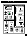
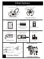
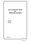
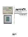
A ll Button and O neTouch™
C ontrol Panels
Important Safety Precautions
When installing and using this electrical equipment, these basic safety precautions should always be
followed:
1.
READ AND FOLLOW ALL INSTRUCTIONS.
LIRE LA NOTICE TECHNIQUE.
2.
DANGER - to reduce the risk of injury, do not permit children to use this product unless they are closely
supervised at all times.
3. All electrical work must be performed by a licensed electrician and must conform to all national, state, and local
codes.
4. WARNING: Water temperature in excess of 100°F/38°C may be injurious to your health.
AVERTISSEMENT: Il peut être dangereux pour la santé de se plonger dans de l'eau à plus de 100°F/38°C.
Prolonged immersion in hot water may induce hyperthermia. Hyperthermia occurs when the internal
temperature of the body reaches a level several degrees above the normal body temperature of 98.6°F/37°C.The
symptoms of hyperthermia include dizziness, fainting, drowsiness, lethargy, and an increase in the internal
temperature of the body. The effects of hyperthermia include: 1) unawareness of impending danger; 2) failure to
perceive heat; 3) failure to recognize the need to exit spa; 4) physical inability to exit spa; 5) fetal damage in pregnant
women; 6) unconsciousness resulting in a danger of drowning. WARNING - The use of alcohol, drugs, or
medication can greatly increase the risk of fatal hyperthermia in hot tubs and spas. La consommation d'alcool ou
de drogue augmente considérablement les risques d'hyperthermie mortelle dans une cuve de relaxation.
5. Install to provide drainage of compartment for electrical components.
6. Install at least five (5) feet (152.4cm) from the inside wall of the pool and tub. Canadian installations must be at least
three (3) meters from the water. Les installations canadiennes doivent se trouver à au moins trois (3) mètres de l'eau.
7. A ground-fault circuit-interrupter must be provided if this device is used to control underwater lighting fixtures. The
conductors on the load side of the ground-fault circuit-interrupter shall not occupy conduit, boxes or enclosures
containing other conductors unless the additional conductors are also protected by a ground-fault circuit-interrupter.
Refer to local codes for complete details.
8. A terminal bar marked GROUND is provided within the Power Center. To reduce the risk of electrical shock, connect
this terminal bar to the grounding terminal of your electric service or supply panel with a continuous green insulated
copper wire equivalent in size to the circuit conductors supplying this equipment, but no smaller than No. 12 AWG
(3.3 mm). In addition, a second wire connector should be bonded with a No. 8 AWG (4.115mm) copper wire to any
metal ladders, water pipes, or other metal within 5 feet (1.52m) of the tub.
9. CONTROL SYSTEM IS INTENDED TO CONTROL HEATERS WITH BUILT-IN HIGH LIMIT CIRCUITS ONLY.
10. PLEASE SAVE THESE INSTRUCTIONS.
SPECIFICATIONS (USA & CANADA):
POWER SUPPLY: 120 Volts A.C.; 60 Hz.; 3 amps.
CONTACT RATING: (High Volt.) 25 amp; 3 h.p. @ 240 Volts A.C.,
1½ h.p. @ 120 Volts A.C.;
1500 Watts Incandescent
CONTACT RATING: (Low Volt.) Class Two, 1 amp at 24V A.C.
EMERGENCY SERVICE SWITCHES: All circuits.
SPECIFICATIONS (EUROPEAN):
POWER SUPPLY: 230-240V~50/60 Hz.; 3 A.
CONTACT RATING: (High Volt.) 25 A; 3 h.p.@240Volts V~
CONTACT RATING: (Low Volt.) Class Two@24V~
EMERGENCY SERVICE SWITCHES: All circuits.
DIMENSIONS (USA & CANADA):
Standard Power Center: Height-13¾"; Width-14½"; Depth-5"
Sub Panel Power Center: Height-20"; Width-14½"; Depth-5"
All Button Control Panel: Length-8"; Width-5"; Depth-1¼"
OneTouch Control Panel Height-4½"; Width-4½"; Depth-1¼"
Four Function Switch: Diameter-2¾"
DIMENSIONS (EUROPEAN):
Standard Power Center: Height-35.3cm; Width-37.2cm; Depth-12.8cm
Sub Panel Power Center: Height-51.3cm; Width-37.2cm; Depth-12.8cm
All Button Control Panel: Length-20.5cm; Width-12.8cm; Depth-3.2cm
OneTouch Control Panel Height-11.43cm; Width-11.43cm; Depth-3 cm
Four Function Switch: Diameter-7.1cm
2
Table of Contents
2
Safety Precautions
Safety Precautions
Specifications
Dimensions
3
Table of Contents
4
System Overview
Controller Package
Power Center
Options and Accessories
5
Other Options
Specialty Boards
TeleLink Kit
Surge Protection Kit
6-7
Basic Plumbing
Standard Plumbing for Pool and Spa
Non-Booster Pump Pressure-Side Pool Cleaner Plumbing
Booster Pump Pool Cleaner Plumbing
Solar System Plumbing
8-11
Power Center Connection
Power Center Preparation
High Voltage Wiring
Low Voltage Wiring (P.C. Board)
12
Auxiliary Power Centers
13-15
All Button Control Panel Wiring
Control panel Wiring
Setup for Multiple Controllers
DIP Switch Settings
16-18
OneTouch Control Panel Installation
Flush Mount
Surface Mount
Templates
19
All Button Programming and System Defaults
20
All Button Reset and Display Messages
21
OneTouch Programming and System Defaults
22
OneTouch Reset and Display Messages
23-25
Four Function Spa Side Switch or SpaLink™ RS
Provisions
Preparation for Installation of Four Function Switch or SpaLink RS
26
27-28
29-30
AquaRite Chlorine Generator Installation
AquaLink ® RS Troubleshooting Quick Check List
AquaLink ® RS Heater Connections
Installation Guidelines
3
31
32
33
34
Cancel Button Flow Chart
All Button Menu Flow Chart
OneTouch Menu Flow Chart
AquaLink ® RS Wiring Diagram
System Overview
*Not Available in CE Models
4
Other Options
Sp ec ia lty Bo a rd s
JVA R e la y In terloc k Bo a rd
A ux ilia ry /JVA Re la y B o a rd
Filter Pum p
(N ormally
Trans forme r
S ocket
Plug in JVA
P3
P6
F I LT E R P U M P K 1
JV A
3
2
1
Re lay Co il
J1
1 2 3 4
Trans forme r
Connect ion
JVA S oc ket
K1
P4
Norm all
y
TB 1
J2
TB2
Norm ally
O pen
Extra R ela y
Socket
Plug into
JVA R e la y A u x B o a rd is u se d to op e ra te
a JV A 2 4 4 0 fro m a ny Au xilia ry
D u a l S p a Sid e S w itc h
Inte rfa c e B o a rd
JVA R e la y In terlo c k B o a rd is u se d to tu rn
o ff o r o n a p ie c e o f eq uip m e n t
a s th e syste m sw itc he s from p o o l to sp a .
Lig h t D im m in g Re la y
N E U TR AL
L IG H T H O T
1 20 VA C H O T
J1
J2
J3
J4
M u ltip le x B oa rd
S w it c h 2
Connec t to
Four
Conductor
W ire
S w it c h 3
R eq u ire d fo r u se w ith tw o or m o re
Sp a Sid e R e m o te s.
Re la y S p litte r
K1
M ultip lex B o a rd is re q u ired w h e n
c o nn ec tin g m o re th a n 2 w ire s o n a
4 p in C o n n ec to r.
R eq u ire d fo r u se w h en u sin g a
d im m er o n a sw itc h e d c irc uit.
2 -Sp e ed R e la y
R eq u ire d fo r u se w ith Aq ua Lin k
R S2 /6 , 2 /1 0 , or 2 /1 4 tw o h e a te rs.
R eq u ire d fo r u se w ith tw o sp e e d
p u m p s.
To Relay 1
To Relay 2
NO
NC
TB 2
J2
D u a l Eq u ip m e n t H e a te r
In te rfa c e Bo a rd
C OM MON
TB3
Plug into
Re lay
Socket
R ela y Sp litter is u se d to tu rn
o n tw o re la ys o ff o n e c irc u it.
Surge Protection Kit *
A ssy # 6800
TeleLink® Kit *
As s bly. # 6941
5
*Not Available in CE Models
*Not Available in CE Models
Basic Plumbing
Non-Booster Pump Cleaner Plumbing
Pool & Spa Plumbing
Plumbing for Pool and Spa Combination.
The diagram to the right shows a simplified version of a
standard plumbing setup for a pool and spa that share
the same filter pump, filter, and heater. The Intake and
Return JVAs (Jandy Valve Actuators) turn simultaneously
so when the Spa button is pressed on the AquaLink® RS
Controller, water circulation switches between pool and
spa. Consult the JVA Installation Manual to ensure that the
Jandy Valve Actuators are "in synch" and rotate properly.
Please also note that if you have a pool only or a spa only,
the diagram does not apply, and if your pool and spa have
separate sets of equipment, you should install an
AquaLink ® RS 2/6 model Controller, designed to control
separate equipment sets.
Non-Booster Pump Pressure-Side
Pool Cleaner Plumbing.
The diagram to the right shows standard
plumbing for a non-booster pump pressure-side
pool cleaner (i.e., Ray-Vac, Energy Sweep, etc.) To
control this cleaner, control water circulation to
the cleaner by using a Cleaner JVA (see right).
Plumb a three-port valve between the filter pump
and the filter. Install a 2-port valve to open and
close the cleaner line, and after the valve, install a
Jandy Energy Filter to provide filtration (as the
main filter has been bypassed). Mount a JVA on
the 2-port valve and set the cam(s) (see JVA
Manual) to turn 90º. Please note the installation of
a non-booster pump pool cleaner requires
moving DIP Switch #1 to the ON position.
6
Basic Plumbing
Booster Pump Pool Cleaner Plumbing.
Booster Pump Plumbing
If you are using a Booster Pump Pool cleaner, plumb the
booster pump so its suction side is connected to the
pool return after the heater and as close to the ground
as is practical (see diagram to the right). Please note
that the installation of a booster pump pool cleaner
requires moving DIP Switch #1 to the ON position.
Solar System Plumbing.
If a solar system is part of the equipment, plumb the solar
feed and return lines between the main filter and the
heater (see diagram to the right). Please be sure to make
provision for solar drain down. Use a Jandy Non-Positive
Seal Valve to provide drain down. Plumb in a solar
booster pump if needed.
If a solar booster pump is installed, follow the
wiring diagram on page 34 for more information.
7
Solar System Plumbing
NOTE: A Jandy (10K) Solar Sensor will be needed for
solar system control. The sensor should be located near
the solar panels and connected to the Power Center by
18 AWG wire.
Power Center Connection - High Voltage
Mount Power Center.
All electrical equipment, except for the Four Function Switch, must be five feet or more from pool /spa and comply with all
national, state and local codes. If using a Jandy Power Center without built-in breaker compartment, install electrical supply
panel with separate breakers for each load. Make sure that motors on equipment have built-in thermal protection. Use the
grounding terminal, provided within the Power Center, for grounding. Bond all equipment, including the Power Center, to
earth ground. (Install to provide drainage for all electrical components.) Mount no less than 5 feet from pool/spa and at least
5 feet off the ground. In areas where lightning strikes are common, install an external surge suppression device.
Run Conduit/Wire from Supply Panel.
Depending on the amount of equipment you want to control, run ¾" or larger conduit from the power supply panel to the
lower side of the Power Center. If you are using the Power Center with built-in breaker compartment, wire power to the
appropriate breakers. Pull in appropriate wire for equipment. Each piece of equipment requires its own high voltage relay.
Connect 120 volts to the power supply terminals. Connect equipment ground(s).
Wire Relay (install additional relays if needed).
For each piece of 240 volt equipment to be controlled, wire line power to the two line terminals of a Relay and wire
equipment to the two load terminals. For each piece of 120 volt equipment, wire power to a line terminal and the equipment
to a load terminal. Order and install optional relay modules if additional equipment is to be installed. Wire all relays and feed
the relay plugs through the holes into low voltage compartment. Plug in relay coils using the wiring diagram on page 34 as
a guide.
Special Relays.
If you have a two-speed pump, you must order and install a two-speed relay. If you wish to install light dimming, you must
order and install a light dimming relay.
Contact Ratings: Do not exceed any rating.
• Standard Relay
3 H.P. at 240 VAC
1 ½ H.P. at 120 VAC
25 Amps
1500 Watts
• Two Speed
2 H.P. at 240 VAC
1 H.P. at 120 VAC
20 Amps
• Light Dimming (12 VAC and 120 VAC)
1000 Watts incandescent
8
Power Center Connection - High Voltage
Power Center Connection - High Voltage
9
*This diagram shows wiring for a standard relay. For light dimming or two-speed
operation, follow wiring instructions included with those relays.
Low Voltage Wiring (Power Center P.C. Board)
Power Center Connection - Low Voltage
If connecting more than 2 items to the RS Power Center red 4 pin terminal bar, a multiplex PCB is required.
10
Power Center Connection - Low Voltage
1. Connect 24V AC Power to Bezel and Mount Bezel.
Plug the orange 24V AC power plug from the transformer into its 3-pin terminal on the back of the Low Voltage Bezel,
feed battery wires to front right and connect the Bezel to the Power Center with the screws provided. DO NOT INSTALL
BATTERY.
2. Mount JVAs & run wires to Power Center.
Refer to the JVA manual to install JVAs. Run JVA wires back to the low voltage compartment of the Power Center,
through low voltage raceway, and plug the JVAs into their sockets. Make certain to plug Intake JVA into Intake socket,
and Return JVA into Return Socket (see diagram). NOTE: Do not coil JVA cable inside Power Center. To shorten cable,
remove JVA lid and undo cable wire nuts. Shorten, strip, and reconnect.
3. Connect Controller Cable to P. C. Board.
Make provision for Cable to be run between the Control Panel and the Power Center. Where cable runs underground or
in concrete, it must be run in conduit. Never run high voltage and low voltage cable in the same conduit. Pull
Controller Cable into low voltage compartment. Strip back cable jacket 6". Strip each wire ¼" and connect to the red 4pin connector. Wire according to the Power Center P.C. Board Wiring Diagram. A Multiplex Kit may be required if
connectong more than two wires to a 4-pin connector.
4. Install Spa Side Switch or SpaLink RS and connect to Terminals.
Spa Side Switch or SpaLink RS (optional)
Follow the instructions included with the Spa Side Switch or SpaLink RS to mount and wire.
NOTE: If more than one Spa Side Switch will be installed, an additional interface board is required,
Dual Spa Side Switch kit, Part No. 6588. For the SpaLink RS, a Rev. G or newer PPD is required and if more than one
SpaLink will be installed, a Multiplex Kit is required.
Radio Remote, and TeleLink Telephone Interface
To install, follow the instructions included with these optional items.
5. Connect Sensors to Terminals.
Water Temperature Sensor.
Drill 3/8" hole in pipe between filter pump and filter. Insert sensor and use clamp (provided) to hold in place. Remove
the 10-pin terminal bar (green) from the PCB. Connect sensor wires to the 10-pin terminal bar as shown on the wiring
diagram on page 34.
Freeze/Ambient Air Temperature Sensor (required). Air Sensor must be installed.
Install sensor outdoors where it will be subjected to shaded air temperature (not in sun). Connect sensor wires to the
10-pin terminal bar as shown on the wiring diagram. Connect other sensors to 10-pin terminal bar as shown on wiring
diagram.
Solar Temperature Sensor (optional)
Install sensor adjacent to solar panels. Connect sensor wires to the 10-pin terminal bar as shown on the wiring
diagram. Connect other sensors to 10-pin terminal bar as shown on wiring diagram. NOTE: If a solar sensor is not
installed, the solar button can be labeled and used as an auxiliary.
6. Connect heater to Low Voltage Terminal.
(All gas heaters or heat pumps with thermostatic circuitry of 24V AC or less)
a. If you are connecting a Low Voltage heater, connect two 18-gauge wires, designed for use in hot environments, to the
proper terminals on the 10-pin terminal bar. If you are connecting a High Voltage heater (not electronic ignition), you must
instead connect the heater to a high voltage relay on the Power Center.
b. Bring the 2 heater wires from the P.C. Board over to the heater and wire nut in series with heater circuitry as if you
were wiring a fireman's switch or a heater delay.
c. Turn the heater thermostat to maximum.
d. Turn heater toggle switch on.
e. Do not disconnect high limit or pressure switches.
NOTE: For connection to specific heater brands, please see the Heater Connection Installation Guidelines.
For Laars LX Heater (If the AquaLink RS has Rev. "I" or higher the LX must have a microprocessor
with Rev. "C-10" or higher)
a. Remove LX GUI from the heater and turn the GUI over.
b. Run 4 conductor cable (red, black yellow, green) from the LX GUI red 4 pin terminal bar to the RS Power Center red 4
pin terminal bar.
c. If connecting more than 2 items to the RS Power Center red 4 pin terminal bar, a Multiplex Kit is required.
d. Replace the LX GUI on the heater.
7. Connect All Equipment to P.C. Board.
Connect the high voltage relay plugs into their appropriate sockets according to the wiring diagram located on the
inside of the Power Center door or on page 34 of this manual.
8.
Set DIP Switches.
See page 14 to set DIP Switches for optional operation features.
11
9. Turn on power to system, then connect 9-volt battery. (Do not connect battery if power is not supplied to unit).
10. Install Power Center Faceplate.
Use the screws provided to install and secure the Power Center Faceplate on to the Power Center.
Auxiliary Power Centers
Auxiliary Power Center Installation
You may have up to four (4) power centers on one (1) AquaLink RS system.
The four conductor RS485 cable going to the 4-pin (red) terminal bar on the auxiliary power centers can be wired either from
the main power center, the indoor control panel or an optional accessory.
The auxiliary power centers can be located anywhere on the property, depending upon convenience and what devices are
being controlled.
AUX B1 through B8, C1 through C8, and D1 through D8 on the indoor control panel operates the relays located in the
auxiliary power centers. AUX B1 through B4 JVA sockets are energized when AUX B1 through B4 relay sockets are
energized.
Note: If you are installing more than one accessory board, order and use a Jandy Multiplex Kit (p/n 6584). Never put more
than two wires into each of the pins of the terminal bar. Use the multiplex board whenever more than two of the 4-wire cabes
are being joined.
12
All Button Control Panel Installation
Prepare Control Panel Site.
With the aid of the homeowner, find the best location for the Control Panel. To ensure the Control Panel is level, hold the
Mounting Bracket against the wall and mark the top inside of the upper right screw hole. Using this mark as a guide, place a
level against the mounting wall and draw a horizontal line 4¼ inches to the left. Now use the Bracket as a template to mark
holes for mounting screws (lining up the holes to the horizontal line). Drill ¼" holes for each screw and insert plastic anchors.
Mount Bracket and secure in place.
Connect Control Panel Cable to Control Panel.
Pull Control Panel Cable through the hole in the Mounting Bracket. Strip back cable jacket 6". Remove the terminal bar from
the Control Panel P.C. Board, and wire Control Panel cable according to the wiring diagram on the back of this manual.
Connect the terminal bar to the Control Panel. Mount the Control Panel by putting the top in place first, then swinging the
bottom in until the snap catches.
Cancel
Delay
W2
W1
Multiple Control Panels
Control Panel (Back View)
13
NOTE: If you are installing
multiple Indoor Control Panels,
you must "address" each one
differently. Refer to instructions
on following page for
additional Control Panel(s).
Setup for Multiple Control Panels
All
Button
Control
Panel
First Control Panel
Third Control Panel
Second Control Panel
Fourth Control Panel
Jumpers
W2
W1
AquaLink RS Control Panel Jumper Setting: Move these jumpers
only when installing more than one Control Panel on a system.
The jumpers are used to give each Control Panel a unique
system address. If you are using this Control Panel to replace an
existing one, ensure the jumper settings match those on the one
being replaced.
Micro
Processor
OneTouch
Control
Panel
Red 4 pin
connector
The AquaLink RS allows each system to support a maximum of four Indoor Control Panels. The Control Panels
may be wired "In Series", starting from the first Control Panel (solid line), or each may be wired individually from
the AquaLink Power Center (dotted line), or a combination of the two. To accomplish the "In Series" wiring
scheme, you may "double-up" wires in the red terminal bars, but never put more than two wires into each pin of
the terminal bars. If you need to join more than two of the 4-wire cables, order and install Jandy Part # 6584
(Multiplex PCB Kit).
M
T
OR
M
T
OR
M
T
OR
14
DIP Switch Settings
Use a pen or small tip screwdriver to slide switch
to the right to turn on.
DIP #1 ON - —AUX 1 CONTROLS POOL CLEANER:
If you installed a booster pump for a pool cleaner, the relay coil for the booster pump must be plugged into the AUX 1 relay
socket. If a non-booster pump cleaner is installed, plug the JVA into the cleaner JVA socket. Turn on DIP Switch #1.
• Main filter pump turns on whenever cleaner turns on.
• Cleaner will not turn on until filter pump has been on for 3 minutes (to ensure priming of system).
• Cleaner turns off when water circulation is to spa.
• Cleaner turns off when spa overflow feature is activated.
• Cleaner turns off for 3 minutes when solar is activated (to ensure air is purged from system).
• AquaLink RS Controller Display reads “CLEANER” rather than “AUX 1”.
DIP #2 ON - —AUX 2 CONTROLS LOW SPEED OF FILTER PUMP:
Turn this switch on if you want to control both speeds of a two-speed filter pump. With this switch on, the filter pump button
on the AquaLink RS Controller will control high speed and the AUX 2 button will control low speed. IMPORTANT: You must
also install a Jandy Two-Speed Relay, purchased separately. Install the Relay according to its installation instructions.
DIP #3 ON - A
— UX 3 CONTROLS SPA SPILLOVER (OPERATES WITH POOL/SPA COMBINATION UNITS):
Turn this switch on, and when the AUX 3 button on the AquaLink RS Controller (or Spa Side Switch) is pressed, the Return
Valve Actuator will rotate to spa circulation. Because the Intake Valve Actuator does not rotate, the spa will fill with water
and overflow into the pool. NOTE: Leave AUX 3 relay socket empty.
DIP #4 ON - HEATER COOL DOWN DISABLED:
Turn this switch on to disable the heater cool down safety feature on the AquaLink RS. WARNING: Turn this DIP Switch on
only if you are using an electric heater or heat pump that does not retain residual heat. If you are turning this switch on for
service purposes, be sure to turn it back off after you have finished.
DIP #5 OFF - FACTORY USE ONLY:
This switch is used for calibration by Jandy technicians only, and to momentarily display the solar temperature.
Please leave this switch in the off position.
DIP # 6 ON - Change Spare AUX. to active when Filter Pump is on and system is in spa mode (pool/spa combination
units only).
DIP #7 - —NOT USED.
DIP #8 ON - HEAT PUMP INSTEAD OF GAS HEATER:
Turn this switch on if you have installed a heat pump instead of a gas heater.
15
OneTouch Control Panel Installation
This document gives instructions for installing the Jandy
®
AquaLink RS OneTouch Indoor Control Panel (surface
and flush mount). The instructions must be followed
exactly. Read through the instructions completely before
starting the procedure.
A . Installing the Flush Mount
Control Box
1.
2.
Upper Flange
Determine the location of the controller. Be sure there is
nothing behind the sheetrock where the controller will be
mounted.
Place Template 1 in the location chosen for the control
panel, cut a square in the sheetrock. Be careful to cut
accurately with a razor knife or equivalent. Do not make
the square oversized.
3.
Run the 4 conductor wire, and pull it through the hole in the
wall.
5
Pull the 4 conductor wire through the large hole in the flush
mount box. Then push the box into the wall.
6.
Depending on what size sheet rock (5/8" or 1/2") determine
which side of the cleat to be used.
a.
For 1/2" sheet rock face the large side of the cleat
towards you (see Fig. 2).
b.
For 5/8" sheet rock, face the small side of the cleat
towards you (see Fig. 2).
This Side and
Tip for 1/2"
Sheetrock
This Side and
Tip for 5/8"
Sheetrock
Lower Flange
Figure 2. Cleat Orientation
7.
Insert a screw through the screw boss. Put a cleat into the
top “U” shaped hole (with the orientation determined in
Step 4). Thread the screw into the cleat. Hand tighten with
a Phillips screwdriver. Repeat with second screw and
cleat using the bottom hole. (see Fig. 3 & 4).
Screw
Bosses
Slot Openings
Through Top,
Bottom, and
Back Walls
Figure 3. Cleat Location
Slide cleat
into slot
opening,
thread screw
into cleat.
Flush
Mount
Box
Sheetrock
(1/2" or 5/8"),
with 4" Square
Cut Out
Lower flanges of
cleat prevent the
part from falling
through the
flush mount box.
Upper flanges of
cleat provide a
snap fit with top
wall of box.
This allows the
screw to be
inserted without
having to hold
the cleat
Outside Wall Surface
Figure 1. Flush Mount Box Positioned in Sheetrock
Figure 4. Cleat Location
16
OneTouch Control Panel Installation
Face Plate
Face Plate
PCB w/LCD &
Buttons
PCB w/LCD &
Buttons
Surface Mount
Box
Flush Mount
Box
Figure 5. AquaLink RS One Touch (surface and flush mount) Assembly
8.
Place the PCB w/LCD and buttons back into the box. Be
sure the rubber washer is between the screw head and the
PCB. Hand tighten the screws. Snap the cover over the
box.
B . Installing the Surface Mount
Control Box
1.
Determine the location of the controller. Be sure there is
nothing behind the sheetrock where the controller will be
mounted.
2.
Place Template 2 in the location chosen for the controller,
mark the holes for drilling. Drill the holes to fit the sheet
rock anchors (recommended drill bit size is 3/16"). Install
the sheet rock anchors. Drill the 1¼” hole for the 4 conductor wire.
3.
Pull the 4 conductor wire through the 1¼” hole in the
surface mount box. Mount the box to the wall using the
screws provided with the product.
4.
Place the PCB w/LCD and buttons back into the box. Be
sure the rubber washer is between the screw head and the
PCB. Hand tighten the screws. Snap the cover over the
box.
5.
Figure 6 shows the locations of the Cancel Button and the
Reset Button on the OneTouch PCB.
17
Reset Button
JA N D Y A qu a L in k R S
0 1 /3 1 /00 M O N
6 :0 0 PM
F ILT ER PU M P O F F
A IR 7 9
E Q U IP M E N T O N /O F F
O N E T O U C H O N /O F F
M E N U / H E LP
Cancel Delay
Figure 6. Location, Cancel Delay and Reset Buttons
OneTouch Installation Templates
Template 1- Flush Mount
4.03"
WARNING
Do not cut
the sheetrock
any bigger than
the template.
4.03"
Figure 7. Flush Mount Template
Template 2- Surface Mount
Drill Thru 3/16"
(3) Places
Drill Thru 1¼”
Figure 8. Surface Mount Template
18
All Button Control Panel Programming and System Defaults
Basic Programming.
To set a particular piece of equipment to turn on and off at
predetermined timeS, press the MENU button, scroll to the PROGRAM
MENU, press ENTER, and then press the button for the equipment that
you want to program. The Controller Display will ask you to enter the
day. Use the arrow keys <—>* to select, and press ENTER. The display
will now ask you for the starting time and ending time. Repeat this
process for each piece of equipment that you wish to program. You may
enter as many programs as needed for each piece of equipment.
Set the Time.
To set the time, press the Menu button. Use the arrow keys to scroll to
the SET TIME Menu and press ENTER. Now scroll to the correct year
and month and press ENTER. Scroll to the correct hour and minute and
press ENTER.
Depending on the age of the AquaLink RS, the following items can be
found either in the Main Menu or in a Sub Menu under SETUP:
Set the Temperature.
Press the MENU button, scroll to the SET TEMP Menu item and press
ENTER. Use the arrow keys to select POOL or SPA and again, press
ENTER. Once you have selected which heater to set the temperature for,
use the arrow keys to move to the desired temperature, and press
ENTER, to complete.
Label Auxiliary Functions.
To label Auxiliary functions, press the MENU button. Scroll to SYSTEM
SETUP and press ENTER, then scroll to the LABEL AUX Menu and
press ENTER. Press the button to be labeled (example: AUX 1). Scroll
to the desired label and press ENTER. Repeat for all functions.
NOTE 1: The labels "TIMED AUX", "AIR BLOWER", and "FILL LINE" are
30 minute timed circuits. NOTE 2: If DIP switch 1, 2 or 3 are on,
Auxiliaries 1, 2 and 3 are labeled CLEANER, LOW SPEED and
SPILLOVER respectively and cannot be relabeled.
Set Spa side Switch or SpaLink RS Functions.
The buttons on the Spa Side Switch or the SpaLink RS may be set to
control any functions the home owner wishes. To the right is a list of
default settings for the Switch. If you wish to change which functions the
Switch(es) control, first press the MENU button. Scroll to SYSTEM
SETUP and press ENTER, then scroll to FOUR FUNCTION SWITCH
(SPA SWITCH on Rev. G or higher) or SPA LINK and press ENTER.
Follow the prompts to assign each REMOTE button.
Set Freeze Protection.
AquaLink RS Freeze Protection senses when the air temperature falls
below 38º F and automatically turns on the filter pump to circulate the
water, thus preventing freezing of pipes. To add freeze protection to
other equipment, press the MENU button. Scroll to SYSTEM SETUP
and press ENTER, then scroll to FRZ PROTECT and press ENTER.
Press the button for the equipment you want to protect.
Assign JVAs.
The Assign JVAs Menu lets you assign Jandy Valve Actuators (JVAs)
to any auxiliary button. This means that whenever you press that
auxiliary button, a valve turns. On pool/spa combination models,
there are two JVA Valve Actuators that can be assigned to auxiliary
buttons: the Cleaner JVA and the Solar JVA. On pool only/spa only
models, there are four JVAs available. The AquaLink RS installer
must set up these JVAs for this feature to operate correctly.
Assigning JVAs lets the owner control certain features like
diverting water to a waterfall or bank of spa jets.
19
Default Time
Default Time - 1:00 P.M.
Default Day - MONDAY
Default Date - 01/31/00
Default Temperature
Default Pool Temp - 80ºF.
Default Spa Temp - 102ºF.
Default Temperature
Default Switch Setting
Button 1 - Spa (Filter Pump)*
Button 2 - Spa Heater (Temp1)*
Button 3 - AUX 1
Button 4 - AUX 2
* pool/spa only controls.
Default Freeze Protect. Settings
FILTER PUMP: Freeze Protection ON. ALL OTHER
EQUIPMENT, Freeze Protection OFF.
NOTE: If you select SPA to be freeze protected,
water circulation will switch between pool and spa
every 30 minutes during freezing conditions once
freeze mode is active.
How to assign values:
1. Press the MENU button. Use the FORWARD and BACK
buttons to move to SYSTEM SETUP. Press ENTER. Use
FORWARD button to move to ASSIGN JVAs Menu and
press ENTER. The AquaLink RS display will read
CLEANER JVA <—>*. If both JVAs are being used, you
will not be able to use this Menu.
2. Use the FORWARD and BACK arrows to choose
among the JVA's listed. When the JVA you want to assign
to an auxiliary is displayed, press ENTER.
3. The AquaLink RS display will read SELECT AUX TO
ASSIGN JVA TO. Press the button of the Auxiliary
that you want to activate the JVA.
All Button Control Panel Reset and Display Messages
Reviewing:
To review equipment, press the MENU button, then use the FORWARD arrow to scroll to the REVIEW menu. Press ENTER,
use the arrows to scroll to the item you wish to review, and press ENTER again.
Canceling Items:
If you make a mistake in programming or you want to change, for example, the ON/OFF times for a specific device, you can
cancel programs for that piece of equipment. For example, to CANCEL A DIMMER, press the CANCEL button; use the
forward and back buttons to advance to DIMMERS and press ENTER. The AquaLink RS display will prompt to select an Aux.
Press the button of the Auxiliary for which you want to cancel the dimmer.
If you want to cancel a JVA assignment, first press the CANCEL button (if no JVAs are assigned, you cannot use this
function). Use the FORWARD and BACK arrows to advance to JVA ASSIGNS and press ENTER. The AquaLink RS display
will read CLEANER JVA. Use the FORWARD and BACK arrows to toggle between JVAs to cancel. When the JVA
assignment that you want to cancel is displayed, press ENTER. The AquaLink display will read PRESS ENTER TO CANCEL
JVA ASSIGNMENT,
or CANCEL TO ABORT. Press ENTER to cancel the JVA assignment, or press CANCEL to abort.
Resetting the System:
To remove all labeling, programming, assignments, and temperature settings, press the MENU button, scroll to CLEAR
MEMORY and press ENTER twice.
Power Center Service Switch:
AUTO Mode (automatic):
The Controller has complete control of all functions. All programmed settings will operate. All safety delays and equipment
protection interlocks are operational.
SERVICE Mode:
The Power Center has complete control of all functions. Service Mode must be turned On/Off at the Power Center. No
programmed settings will operate. CAUTION: In service mode, the safety interlocks for equipment protection are overridden.
TIMEOUT Mode:
The Power Center has complete control for 3 hours. After 3 hours, the system will return to Auto Mode. Programmed On/Off
times will be overridden during the 3 hours. After the three hour "time-out", the system will resume any programmed times
that were overridden.
Battery Back-Up:
A nine-volt battery is located at the Power Center. Do not install battery in the Power Center until system is ready to operate.
Battery will drain if power is left off. Review DIAGNOSTICS in the SYSTEM SETUP section of the Menu. The DIAGNOSTICS
will indicate when the battery needs replacement.
Light Dimmer:
Dimmers can be set at 25%, 50%, 75% or 100%, depending upon the amount of light desired, by pressing the AUX assigned
as a dimmer and using the arrow <—>* buttons to dim or brighten. Once desired brightness is achieved, press ENTER.
Press AUX to turn off.
NOTE: When light is turned back on, it will automatically return to brightness last set.
From the Spa Side Switch or SpaLink RS, light dimming operates as follows:
When a button assigned to a light dimming auxiliary is pressed, the light will turn on at full brightness, and each press of
the button will decrease brightness 25% until light is off.
Special Note to "Start-up Person":
The AquaLink RS allows you two options for operating the pool equipment for the first day of operation:
Option #1 - Once all programming of equipment is completed, go to the Power Center Service Switch. Push the Switch
three times which moves from "AUTO" to "SERVICE" to "TIME-OUT" and finally back to "AUTO". The
AquaLink RS will now "look back" (review) all programs and turn on any equipment which is programmed to
be on. Close up system; it will now operate as programmed.
Option #2 - If you want the filter pump or cleaner to operate continually for the first day, leave the Power Center Service
Switch in "AUTO" mode. Go to the indoor controller and press the AUX buttons for the equipment you want
to run. The equipment activated will now run continuously, ignoring the first programmed off time, and turn
off at the programmed off time for the next day.
20
OneTouch Control Panel Programming and System Defaults
Basic Programming.
To set a particular piece of equipment to turn on and off at
predetermined times, highlight EQUIPMENT ON/OFF and press select.
To highlight an item, use the up or down buttons. Use the SELECT
button to turn the equipment on or off. After turning a piece of equipment
on, return to the main menu by using the back button. Repeat this
process for each piece of equipment that you wish to program. You may
enter as many programs as needed for each piece of equipment.
KEY HELP
PAGE UP
UP
BACK
DOWN
PAGE DOWN
CONTINUE
Set the Time.
To set the time, highlight MENU/HELP press select, highlight SET TIME
and press select. Use the arrow keys to set values, press SELECT to
continue.
The following items can be found either in the MENU/HELP or in a Sub
Menu under SYSTEM SETUP:
Set the Temperature.
To set the pool and spa thermostats, highlight MENU/HELP press select,
highlight SET TEMP and press select. Use the arrow keys to highlight
either pool or spa and press select. Use the arrow keys to increase or
decrease the temperature.
Label Auxiliary Functions.
Default Time
Default Time - 1:00 P.M.
Default Day - MONDAY
Default Date - 01/31/00
Default Temperature
Default Pool Temp - 80ºF.
Default Spa Temp - 102ºF.
Default Temperature
To label Auxiliary functions, highlight MENU/HELP press select,
highlight SYSTEM SETUP press select, highlight LABEL AUX and press
select. You can choose a name from general, light or waterfall labels or
enter a custom name by using the arrow keys to change letters and
using the select key to move to the next letter.
Set Spa Side Switch or SpaLink RS Functions.
To set the Spa Side Switch or SpaLink RS, highlight MENU/HELP press
select, highlight SYSTEM SETUP press select, highlight SPA SWITCH or
SPA LINK and press select. Highlight the number of remotes you have
and press select. Use the arrow keys to move the highlight bar to choose
which button you are assigning, press select. Use the arrow keys to
move the highlight bar to choose which piece of equipment will be
associated with the button, press select. After pressing select on the
piece of equipment, you will be returned one screen to continue
assigning Spa Side Switch or SpaLink RS buttons.
Set Freeze Protection.
To set freeze protection, highlight MENU/HELP press select, highlight
SYSTEM SETUP press select, highlight FREEZE PROTECT and press
select. Use the arrow keys to change temperature. Once the temperature
is set use the select button to move to the next screen to assign freeze
protection to a selected piece of equipment. Note: the filter pump is
always assigned to freeze protection.
Assign JVAs.
To assign JVA's, highlight MENU/HELP press select, highlight SYSTEM
SETUP press select, highlight ASSIGN JVAs and press select. Highlight
the JVA you wish to assign and press select.
21
Default Freeze Protect. Settings
FILTER PUMP: Freeze Protection ON. ALL OTHER
EQUIPMENT, Freeze Protection OFF.
NOTE: If you select SPA to be freeze protected,
water circulation will switch between pool and spa
every 30 minutes during freezing conditions once
freeze mode is active.
OneTouch Control Panel Reset and Display Messages
Resetting the System:
To remove all labeling, programming, assignments, and temperature settings, highlight MENU/HELP press select,
highlight SYSTEM SETUP press select, highlight CLEAR MEMORY and press select. Select CONTINUE, then select
either yes or no to clear memory. There will be a 15 second delay before you see the FINISHED screen, select
CONTINUE to return to SYSTEM SETUP.
Power Center Service Switch:
AUTO Mode (automatic):
The Controller has complete control of all functions. All programmed settings will operate. All safety delays and
equipment protection interlocks are operational.
SERVICE Mode:
The Power Center has complete control of all functions. Service Mode must be turned On/Off at the Power Center. No
programmed settings will operate. CAUTION: In service mode, the safety interlocks for equipment protection are
overridden.
TIMEOUT Mode:
The Power Center has complete control for 3 hours. After 3 hours, the system will return to Auto Mode. Programmed On/
Off times will be overridden during the 3 hours. After the three hour "time-out", the system will resume any programmed
times
that were overridden.
Battery Back-Up:
A nine-volt battery is located at the Power Center. Do not install battery in the Power Center until system is ready to
operate. Battery will drain if power is left off. Review DIAGNOSTICS in the SYSTEM SETUP section of the Menu. The
DIAGNOSTICS will indicate when the battery needs replacement. The battery will keep the clock running during power
outages.
Light Dimmer:
Dimmers can be set at 25%, 50%, 75% or 100%, depending upon the amount of light desired. Use the DIMMERS menu
under SYSTEM SETUP to assign an auxiliary to be dimmed. Note: you must install a light dimming relay.
From the Spa Side Switch or SpaLink RS, light dimming operates as follows:
When a button assigned to a light dimming auxiliary is pressed, the light will turn on at full brightness, and each press of
the button will decrease brightness 25% until light is off.
Special Note to "Start-up Person":
The AquaLink RS allows you two options for operating the pool equipment for the first day of operation:
Option #1 - Once all programming of equipment is completed, go to the Power Center Service Switch. Push the
Switch three times which moves from "AUTO" to "SERVICE" to "TIME-OUT" and finally back to "AUTO".
The AquaLink RS will now "look back" (review) all programs and turn on any equipment which is
programmed to be on. Close up system; it will now operate as programmed.
Option #2 - If you want the filter pump or cleaner to operate continually for the first day, leave the Power Center
Service Switch in "AUTO" mode. Go to the indoor control panel and highlight EQUIPMENT ON/OFF press
select, then select the equipment you want to run. The equipment activated will now run continuously,
ignoring the first programmed off time, and turn off at the programmed off time for the next day.
22
Four Function Spa Side Remote Provisions
The Four Function Spa Side Remote is a double insulated, submersible device which is ETL listed (to UL
Standard 1563) for installation at the water’s edge. It is typically installed at the tile-line of the spa wall, or in
the deck within arm’s reach of the spa. It can be used with a gunite spa, acrylic spa, or hot-tub.
When installing the Four Function Remote, it is important to make provisions for this hard-wired remote
before the pool/spa construction is complete by running electrical conduit from the desired remote
location to the future Power Center location. Do not install the Four Function Remote until construction of spa
and deck is complete.
1. Install a 6" piece of 1½” or 1" schedule 40 PVC pipe in the pool/spa wall so that the Four Function Remote
will not be constantly submerged. A 1½” to 1" adapter is included for use if 1½” PVC pipe is being used. This
pipe will house the remote installed vertically in the wall of the pool or spa. Carefully trim the end of the pipe
flush with the wall after all tile work is completed. There must be least 2" of clearance from coping stones or
other raised objects to the schedule 40 pipe.
2. Install a ½” or ¾” reducer to the bottom of the 6" piece of pipe and run a ½” or ¾” electrical conduit
underground from the reducer to the future AquaLink ® RS Power Center location see page 10 of AquaLink ® RS
Installation Manual for further details on Power Center). Use sweep elbows (do not use 90° elbows) for turns
so that you can easily pull the remote cable later.
3. Use a snake (or similar tool) to pull the Four Function Remote cable through the conduit to the Power
Center.
4. At the Power Center, feed the remote cable into the low voltage compartment (left-hand side). Strip the
cable jacket 4" and strip each wire ¼”. Use the P.C. Board Wiring Diagram on the inside of the Power Center
door to locate the Four Function Remote terminals. Wire the remote according to the diagram.
5. At the Remote mounting location, press (do not screw) the Four Function Remote into the PVC pipe.
NOTE: Do not alter the Four Function Remote housing. Cutting the housing may damage its seal and will void
the warranty.
When replacing an old, threaded body style remote with a new four function remote, place 1/8" bead of
silicone sealant around base of remote and let cure. Add extra silicone sealant and install remote into
threaded adapter.
6" of 1½" to 1"
schedule 40 PVC pipe
1½" to 1" adapter
(to fit into 1½" pipe)
½" to ¾" schedule
40 PVC conduit (to
Power Center)
Edge of
Pool/Spa
1 3/8" Diameter
23
NOTE: Do not install Four
Function Remote until
construction of spa and
deck is complete.
Pool/Spa Tile
SpaLink® RS Remote Provisions
NOTE: For use with an AquaLink® RS System, ONLY! AquaLink RS software revision must be Rev.
“G” or later.
For Vertical Installation into the Spa Wall:
Install a 6" piece of 1½” or 1" schedule 40 PVC pipe in the pool/spa wall so that the SpaLink RS Remote will not be
constantly submerged. A 1½” to 1" adapter is included for use if 1½” PVC pipe is being used. This pipe will house the
remote installed vertically in the wall of the pool or spa. Carefully trim the end of the pipe flush with the wall after all tile
work is completed. There must be least 2" of clearance from coping stones or other raised objects to the schedule 40
pipe.
Install a reducer to the end of the 6" piece of pipe and run a ½” or ¾” electrical conduit underground from the
reducer to the AquaLink RS Power Center location (see page 10 of the AquaLink RS Installation Manual for further
details on the Power Center). Use sweep elbows for turns (do not use 90° Elbows) so that the SpaLink RS cable can
be easily pulled through later.
Use a snake (or similar tool) to pull the SpaLink RS cable through the conduit to the Power Center. At the Power
Center, feed the SpaLink RS cable into the low voltage compartment (left side). Strip the cable jacket 4” and strip
each wire ¼”. Use the P.C. Board Wiring Diagram on the inside of the Power Center door to piggyback (double-up) the
SpaLink RS wires with the 4-pin terminal bar. See the Wiring Diagram on page 3 of these instructions.
Apply a silicone sealant around the edge of the cone-shaped base of the SpaLink RS and slide it into the adapter (if
one is being used), then into the PVC. At the mounting location, press (do not screw) the SpaLink RS into the PVC.
Place a 1/8” bead of silicone sealant around back of the SpaLink RS and let cure. NOTE: Do not alter the SpaLink RS
housing. Cutting the housing may damage its seal and will void the warranty.
Dimensions:
Length: 6½" w/frame: 7½"
Width: 2½"
w/frame: 3½"
Height: 1"
w/frame: 1"
NOTE: A bonding lug is provided with the SpaLink RS
package. The RS Power
Center must be both bonded
and grounded.
1½" to 1" Adapter
(to fit into 1½" PVC pipe)
Apply silicone sealant around
the boss of the SpaLink before
sliding it into the Adapter and
PVC
Apply 1/8" bead of silicone
sealant around the edge of the
SpaLink before sliding it into
place
1" or 1½" Schedule
40 PVC pipe
½" to ¾" schedule
40 PVC conduit (to
Power Center)
Edge of Pool/Spa
Pool/Spa Tile Line
SpaLink RS Control
24
SpaLink® RS Remote Provisions
For Horizontal Installation into the Deck:
To house the SpaLink RS, plumb a 6" long piece of 1"
schedule 40 PVC pipe. A 1½” to 1” adapter is included for use if
3¼"
1½” PVC is being used. Carefully trim the end of the pipe flush
with the deck after all the deck work is completed. Leave at least
1"
2” of clearance around the conduit from coping stones or other
raised objects.
SpaLink
Install a reducer to the end of the 6" piece of pipe and run ½”
Control
or ¾” electrical conduit underground from the reducer to the
AquaLink RS Power Center location (see page 10 of the
“O” rings
AquaLink RS Installation Manual for further details on the Power
1½" to 1" Adapter
Center). Use sweep elbows for turns so that the SpaLink RS
(to fit in 1½" pipe)
cable can be easily pulled through later.
Use a snake (or similar tool) to pull the SpaLink RS cable
through the conduit to the Power Center. At the Power Center,
feed the SpaLink RS cable into the low voltage compartment (left1½"or 1"
hand side). Strip the cable jacket 4” and strip each wire ¼”. Use
schedule
the P.C. Board Wiring Diagram on the inside of the Power Center
40 PVC pipe
door to piggyback (double-up) the SpaLink RS wires with the 4Concrete
pin terminal bar.
Deck
Apply a silicone sealant around the edge of the cone-shaped
½" or ¾"
base of the SpaLink RS and slide it into the adapter (if one is
electrical conduit
being used), then into the PVC. At the mounting location, press
w/ sweep elbows
(do not screw) the SpaLink RS into the PVC. Place a 1/8” bead of
for turns
silicone sealant around back of SpaLink and let cure. NOTE: Do
not alter the SpaLink RS housing. Cutting the housing may
damage its seal and will void the warranty.
Mud Box Installation for Flush Mount SpaLink RS Remote.
If using the SpaLink RS Mud Box, it is important to make provisions for the hard-wired
SpaLink® RS Control before the pool/spa construction is complete by running
electrical conduit from the desired SpaLink location to the Power Center location.
However, do not install the SpaLink until construction of spa and deck is complete.
1. The mud box is for use with new SpaLink housing and frame only. This mud
box will not work with the old style SpaLink.
2. Use the dimensions below to make space for the mud box.
3. Install a one (1") inch PVC conduit from the Power Center to the back of the mud
box, so that the SpaLink RS Remote will not be constantly submerged.
4. The mud box's fitting is smaller than one (1") inch to allow
movement of the mud box within the PVC conduit. Use caulking
7.25"
or RTV to make up for the loose fit.
5. The smaller outlet on the mud box is for water drainage (if
needed).
a. Cut the end of the nipple and run a piece of tubing to the
nipple.
b. Run a piece of tubing to an appropriate spot away from the
mud box.
6. Place the SpaLink w/frame and "O" rings into mud box. The
SpaLink is smaller than the mub box to allow movement if the
mud box is not level. Use silicone sealant to adhere the frame
to the mud box. Apply the silicone to the under side of the
frame.
25
3.3"
2.75"
1.00"
AquaRite® Chlorine Generator Installation
Installation Instructions:
The Jandy AquaLink RS and AquaRite use a 4-wire connection to communicate and can be wired up to 500' apart. Any
outdoor rated 4 conductor cable can be used.
Locate appropriate screw terminals on the circuit board according to the diagram below (screw terminals are removable
to aid in installation).
IMPORTANT: attach wires to like numbered screw terminals on both the AquaRite® and AquaLink RS. Use a Multiplex Kit
if more than two items are connected to any 4-pin connector.
Jandy Aq uaLink RS
4-pin Co nnecto r
To Ind oor
Control P anel
AquaRite
Control
O P TIO N A L
240 VAC
Eng lish /M etric
Jum per
Standard Power Center
120 VAC
Power Center PPD Removal:
Back View of Bezel Assembly
Power Center Printed Circuit Board
(Back of Power Center Board used with Pool/Spa combo unit only)
Spare AUX
PPD Tool
Programmable
Peripheral Device
Spare Aux This socket has power only when the Filter Pump is
on and the pool water is circulating. It has no power
when the system switches to "Spa". It is used on a
pool/spa combination system when the user wishes
to turn off a piece of equipment (such as the
chlorine generator) while the spa is being used.
NOTE: DIP switch 6, in Rev. I software, changes this
Alignment
operation to Spa mode
Arrow
Pry Slots
Using the PPD tool,
pry out the PPD evenly
on both sides.
Beveled Corner
26
AquaLink® RS Troubleshooting Quick Check List
Symptom
Problem
Possible Solution
Power Center override
switches operate when in
Service or Time Out Mode, but
the Controller is completely
dead (no lights on, no display).
Power supply problem.
Check connection of the outside
two wires (red and green) of the
four conductor cable.
If wired correctly, check the voltage between these two wires voltage should be 10 VDC.
All LEDs are on at Controller
and the part # and Rev letter of
the Controller software are
displayed (either 6553 Rev
B01 or 6700 Rev C). The
override switches at the Power
Center operate as they should.
Controller is not communicating
with the Power Center PCB.
Check the two center wires
(black and yellow) of the four
conductor cable. Also check
the installation of the PPD on
the Power Center PCB; if it is
not seated properly the system
will not communicate.
All LEDs on at Controller and
the part # and Rev letter are
displayed, but override
switches at the Power Center
do not operate at all.
1. Check alignment of the PPD.
1. Damaged or improperly
2. If PPD is installed correctly,
installed PPD.
2. Damaged Power Center PCB. replace the Power Center PCB.
Some buttons do not operate
from the Controller, nor from the
Power Center override
switches.
Wrong PPD chip installed at
the Power Center PCB.
Check part number and
revision letter by pressing the
Reset button at the Controller.
The second part number and
Rev. letter displayed is for the
PPD indicating which model.
System locked up.
Microprocessor locked.
Turn off power to system.
Disconnect battery and turn on
power. Reconnect battery and
reset time and date.
27
®
AquaLink RS Troubleshooting Quick Check List
Symptom
Problem
Possible Solution
Power outage with dead
battery.
At Controller, check battery
level. With software level Rev. F
or newer, battery status is
located in Diagnostics section
of System Setup Menu.
One button on the Four Function Switch or SpaLink RS
does not operate.
Check programming first.
If the Four Function Switch or
SpaLink RS is programmed
correctly, the button may be
shorted.
Replace the Four Function
Remote or SpaLink RS.
Use MENU, REVIEW, SPA
SWITCH (or SPALINK) to
check programming
Pool cleaner booster pump
turns on without the filter pump
being on, and can run with the
spa on.
System is not recognizing
DIP Switch 1 is on.
NOTE: Before turning on any
DIP Switches, first turn off all
equipment.
Turn off all equipment buttons,
then turn off power to system,
finally turn off, then on,DIP
Switch 1. Turn on power and
test system.
Cannot assign Cleaner JVA.
DIP switches not set correctly.
DIP Switch 1 must be off, and
DIP Switch 7 must be on to
assign the Cleaner JVA to an
auxiliary (Rev F or older).
Model is one of the AquaLink RS
Dual Equipment, message scrolls
"Adjustable Freeze Sensor Not
Installed".
Normal operation when a Dual
Equipment AquaLink RS is
controlling a solar system and
an adjustable freeze sensor is
not installed.
Either install the adjustable
freeze sensor, or wait 24 hours
and this message will go away.
Phantom programs.
At Controller press Menu, then
scroll, to REVIEW. Make note
of all programs, Four Function
Switch setting, labels, and
temperature settings, then turn
off all DIP switches and go to
the Controller. CLEAR
MEMORY, reprogram and try
system again.
System sometimes does not
run programmed on and off
times.
System comes on at times that
are not programmed.
Heater will not fire.
Heater LED will not light in
"Service Mode".
Water temperature sensor
not installed or defective.
Check water temperature
sensor.
28
AquaLink® RS Natural Gas Heater Connection
Installation Guidelines (also includes propane heaters)
General Heater Wiring Guidelines:
Electric Heaters and Heat Pumps
This instruction sheet is for low voltage heaters. Do not attempt to
connect a heater with a high voltage (110 or 220 VAC) thermostat
into the low voltage heater terminal bar.
MAX
3
ON
4
Natural Gas Heaters and Propane Heaters
1. Connect two 18 gauge wires, designed for use in hot environments,
to the proper terminals on the Heater Terminal Bar.
2. Bring two heater wires from the AquaLink RS P.C. Board over to
the heater and wire in series with the heater circuitry as if you
were wiring a fireman's switch or heater delay.
3. Do not disconnect high limit or pressure switches.
4. Turn the heater thermostat(s) to maximum setting.
5. Turn the heater toggle switch to ON.
5
2
HEATER WIRING
RS BEZEL/PCB
Typical Laars Lite Heater Connection
Guidelines for All Laars Heaters
(except Laars LX):
1. Remove the heater service door.
2. Remove the factory-installed wire between Terminal 1
and Terminal 2 on terminal strip (see diagram at right).
3. Connect the wires from the AquaLink RS P.C. Board
to the two terminals. Teledyne Laars requires heater
hookup wires to be AWG 14-gauge copper with a
temperature rating of 105°F or higher.
4. Set the thermostat selector switch to ON, HIGH or
SPA and set the heater thermostat(s) to maximum.
Heater Wiring
Before Modification
Heater Wiring
with AquaLink RS
To Limit Switches
To Limit Switches
White
White
White
Factory
Installed
Wire
Fusible Link
To
AquaLink
RS P.C.B.
White
Fusible Link
W hite
Green
Yellow
Blac k
Red
Typical Laars LX/LT Heater Connection
Guidelines for Laars LX Heaters
4 3 2 1
W ir ing for
firs t S paLink
Indoor Contr oller
1. Remove the LX GUI from the heater.
2. Run 4conductor cabel (red, black, yellow green) from
the LX GUI red 4 pin terminal bar to the RS Power
Center red 4 pin terminal bar.
3. If connectingmore than 2 items to the RS Power Center
red 4 pin terminal bar, a multiplex PCB is required.
fi
4
O PTI O NA L
P ower Center
RS Control
System
22 Gauge,
4 Conductor
Wire
29
AquaLink®šš RS Heater Connection
Installation Guidelines (Continued)
Typical RayPak Heater Connection
Guidelines for RayPak Heaters:
Heater Wiring with
AquaLink RS
For RP2100: (Models: P-R185A to P-R405A,
C-R185A to C-R405A, P-R185AL to P-R405AL,
C-R185AL to C-R405AL, from Catalog #6000.52-X)
1. For the 2-wire/1 function configuration, connect the orange/
black and black/orange wires to one contact and the yelow/
black wire to the other contact.
To AquaLink RS
System
P7
Terminal
Typical Purex Heater Connection
Guidelines for Purex Heaters:
For MiniMax and Tropical Isle Pool and Spa Heaters:
1. Remove the heater service door.
2. Separate the black wire (common) from each other
(see diagram at right).
3. Connect the wires from the AquaLink RS P.C. Board to the
two black wires as shown. The violet and red wires remain
unused.
4. Turn heater toggle switch ON, and thermostat(s) to MAX.
5. When connecting an AquaLink RS Controller to a Purex
heater, Purex requires that you install the low voltage
thermostat wires in separate conduit from ANY line
voltage wires. Failure to do so will cause the thermostat
relay to react erratically.
Heater Wiring
with AquaLink RS
Heater Wiring
Before Modification
VIO
VIO
BLK
BLK
BLK
BLK
RED
RED
RS
Wires
Typical Hayward Heater Connection
Guidelines for Hayward Heaters:
For HM2 Models 150, 200, 250, 300, 350 and 400:
1. Remove heater service door.
2. Remove factory-installed wire-nut between two red wires
labeled "CONNECTION FOR FIELD INSTALLED
CONTROL SWITCH".
3. Wire-nut two heater wires from AquaLink RS P.C. Board
to the two red wires as shown in the diagram to the right.
4. Set the thermostat selector switch to ON, HIGH or SPA
and set the heater thermostat(s) to maximum.
Heater Wiring
Before Modification
Limit
Switch
Limit
Switch
Factory
installed
wire nut
Pressure
Switch
Heater Wiring
with AquaLink RS
Limit
Switch
Limit
Switch
Wires to
AquaLink RS
Pressure
Switch
30
All Button Control Panel Cancel Flow Chart
CANCEL SOME
PROGRAMS
Select Device
To Be Canceled
CANCEL ALL
FRZ PROTECT
Press ENTER to
Remove All
Devices Except
Pump from Freeze
Protection or
Cancel to Abort
AUX LABEL
Select AUX to
Remove Label From
Label Removed
DIMMERS
Press ENTER to
Cancel Dimmers
or Cancel to Abort
Select AUX to
Remove Dimmer
From
CLEANER JVA
No JVAs Assigned
to AUXs
JVA ASSIGN
SOLAR JVA
SYSTEM
SPA SWITCH
LOCKOUTS
SPA LINK
DEVICE
31
UNLOCKED
All Button Control Panel Menu Flow Chart
On All Days
PROGRAMS
PROGRAM
Select
Equipment
On Weekends
TEMP SET
On Weekdays
SPA SWITCH
On Specific Day
REVIEW
SPA LINK
FRZ
PROTECT
POOL TEMP
AUX
LABELS
SET TEMP
SPA TEMP
DIMMERS
SET TIME
Set Year, Day,
Hour & Minute
SYSTEM
JVA
ASSIGNS
LOCKOUTS
SPA SWITCH
LOCKOUTS
SPA LINK
DEVICE
PGM GROUP
GROUP A
GROUP B
ON
Select
Equipment
Main Label
Menu
DISPLAY LIGHT
OFF
LABEL AUX
SPA SWITCH
1 SWITCH
2 SWITCHES
Assign
Buttons
3 SWITCHES
1 SPA LINK
SPA LINK
2 SPA LINKS
Assign
Buttons
3 SPA LINKS
Assign
Items
Temp
Settings
FRZ PROTECT
AIR TEMP
SYSTEM SETUP
ON
OFF
Fahrenheit
DEGREES F/C
Celsius
Temp Down
TEMP CAL
Temp Up
ASSIGN JVA
Choose JVA
SET DIMMERS
Select
Equipment
DIAGNOSTICS
Diagnostics
Readout
CLR MEMORY
Warning! Clears
All Memory
Choose Button
Aerator
Air Blower
Backwash
Booster Pump
Chem Feed
Cleaner
Color Wheel
Drain Line
Fan
Fiber Optic
Fill Line
Filter Pump
Floor System
Fogger
Fountain
Heat Pump
Heater
Hi-E2
High Speed
Home A/C
Home Heat
Jet Pump
Laars Lite
Lamp
Lights*
Low Speed
Maxx Pure
Mist
Music
Not Used
Ozonater
Pond
Ray-Vac
Slide
Solar Pump
Spa
Spillway
Sprinklers
Stereo
Stream
Swim Jet
Timed Aux
Valve(s)
Wtr Feature
Waterfalls*
Whirlpool
*Item has
sub-menu
Back Light
Basement Light
Beach Light
Bedroom Light
Bug Light
Cabana Light
Color Wheel Light
Deck Light
Dock Light
Drive Light
East Light
Entry Light
Equipment Light
Fan Light
Fence Light
Flood Light
Fountain Light
Front Light
Garage Light
Garden Light
Gazebo Light
Hall Light
House Light
Kitchen Light
Left Light
Light
Light 1
Light 2
Light 3
North Light
Path Light
Patio Light
Perimeter Light
Pond Light
Pool Light
Porch Light
Right Light
Room Light
Sauna Light
Security Light
Shower Light
Shrub Light
South Light
Spa Light
Statue Light
Steps Light
Table Light
Tier Light
Tree Light
Walk Light
Waterfall Light
Wtr Feature Light
West Light
Yard Light
Waterfall
Waterfall 1
Waterfall 2
Waterfall 3
Shr Descent
Rockfall
32
OneTouch Control Panel Menu Flow Chart
O N ETO UC H 1
O N ETO UC H O N/O FF
E Q UIPM E NT O N/O FF
ON
O N ETO UC H 2
O N ETO UC H 3
S elect
E quipme nt
O FF
ON
O FF
K EY S
S ERV ICE
D IA G NO ST IC S
G O BA CK
H ELP
S elect
E quipme nt
P RO G RA M
A DD PR O G RA M
P O O L H E AT
S ET TE MP
S ET TIM E
N EX T
S PA H EAT
S et mont h, d ay,
yea r, and time
ON
D IS PLAY LIG H T
O FF
2 M IN . DE LAY
M E NU/HE LP
LO CK O UTS
S YS TE M
LO CK
S PA S W ITCH
S PA LINK
U NLK
D EV IC ES
P RO G RA M G RO UP
LO CK
S elect
D evic e
U NLK
G R O UP A
G R O UP B
O N ETO UC H
O N ETO UC H 1
S ELE CT NAM E
O N ETO UC H 2
O N ETO UC H 3
C USTO M N AM E
S ET DE V IC ES
G E NE RA L LAB ELS
LAB EL AU X
LIG HT LA BE LS
W TR FALL LA BE LS
S elect
A UX
C USTO M L ABE LS
(Type P ersonaliz ed
Desc ript ion)
FRE E ZE PR O TEC T
S YS TE M S ETU P
A IR TE MP
D EG RE E S C/F
TE MP
E NAB LED
D IS ABLE D
FA HRE NH EIT
C ELS IUS
TE MP CA LIBR ATE
TE MP
IN FL O O R CLE AN
E NAB LED
D IS ABLE D
S O LAR P RIO RITY
E NAB LED
D IS ABLE D
A SS IG N JVA s
OK
G O BA CK
D IM M ER S
OK
G O BA CK
C O LO R W HE ELS
S PA S W ITCH
1
2
3
S PA LINK
P RO DU CT IN FO
C LE AR M E M O RY
33
S elect
D evic e
1
2
3
INTAK E
R ETUR N
C LE AN ER
S O LAR
S elect
D evic e
S elect
Label
ON
O FF
O p t io n a l S e t
ON
C le a n e r
2 spd pum p
S p a S p illo v e r
D is a b l e d
S ee M anual
S p a re A u x S p a
N ot U sed
H eat Pum p
N ot U sed
N ot U sed
R ed
B lack
W a t e r Te m p .
R ed
B lack Senso r
S o la r
S ensor
L o w V o lta g e
H e a te r
R ed
B lack
G re e n
W h it e
B ro w n
B lue
6 5 4 3 2 1
A ux. 1
A ux. 2
J V A S o ck e ts
(2 4 V A C o u tp u t)
To S e ns ors , e tc .
(g ree n t e rm . b a r)
R e la y S o c k e ts (2 4 V D C o u tp u t)
F.P u m p
R e tu rn
S o la r
E le c t.
JVA
JVA
H e a te r
C le ane r
S o lar
In ta k e
JVA
Pump
JVA
R e la y S o c k e ts
(2 4 V D C o u tp u t)
R e la y S o c k e ts (2 4 V D C o u tp u t)
A ux. 3
A ux. 4
A ux. 5
A ux. 6
A ux. 7
B a tte ry
(9 V o lt)
A u x . 7 R e la y
A u x . 1 R e la y
A u x . 2 R e la y
A u x . 5 R e la y
A u x . 6 R e la y
L o a d Tw o
A u x . 4 R e la y
L in e Tw o
A u x . 3 R e la y
Load One
F ilte r P u m p R e la y
L in e O n e
L o w V o lt a g e R a c e w a y (d o n o t ru n h ig h v o lta g e w i re in th is c o m p a rtm e n t)
F a c to ry S e t
O FF
A ux 1
1 s pd pum p
A ux 3
Co ol D own
S ee M a nual
S p a re A u x P o o l
No t Us ed
G as Heater
4 3 2 1
To C o nt rolle r
To R e m o te
(re d te rm . ba r) (b row n t erm . b ar )
D ip S w itch S ettings
#
1
2
3
4
5
6
7
8
G re e n
Y e llo w
B lack
R ed
Power Center Wiring Diagram
S y s te m P o w e r
G ro u n d in g B a r
W ire N u t t o
120 VAC P ower
34
Notes
35
C
US
Listed 4J39
Swimming Pools
& Spa Controllers
6000 Condor Dr., Moorpark, CA, USA, 93021 • 707.776.8200 FAX 707.763.7785
480 S. Service Road West, Oakville, Ontario, Canada L6K 2H4 • 905.844.8233 FAX 905.844.2635
Litho in USA © Water Pik Technologies, Inc.
Sheet #6594, Rev E, 9/01
For Technical Support call 707-776-8200, ext. 260