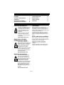
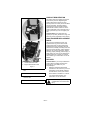
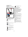
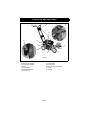
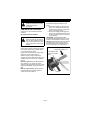
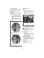
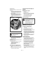
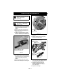
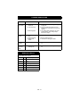
1
Precision Edge
Owner/Operator Manual
Manuel Du Propriétaire/Utilisateur
Model
986101 – Edger
ENGLISH
FRANÇAIS
03818800B 2/09
Printed in USA
TABLE OF CONTENTS
SAFETY . . . . . . . . . . . . . . . . . . . . . . . . . 4
STORAGE . . . . . . . . . . . . . . . . . . . . . . 15
ASSEMBLY. . . . . . . . . . . . . . . . . . . . . . . 7
TROUBLESHOOTING . . . . . . . . . . . . . 16
CONTROLS AND FEATURES . . . . . . . . 8
SERVICE PARTS . . . . . . . . . . . . . . . . . 16
OPERATION . . . . . . . . . . . . . . . . . . . . . . 9
SPECIFICATIONS . . . . . . . . . . . . . . . . 17
MAINTENANCE SCHEDULE . . . . . . . . 13
WARRANTY . . . . . . . . . . . . . . . . . . . . . 18
SERVICE AND ADJUSTMENTS . . . . . 14
INTRODUCTION
NON-ENGLISH MANUALS
THE MANUAL
Manuals in languages other than
English may be obtained from
your Dealer. Visit your dealer or
www.ariens.com for a list of
languages available for your
equipment.
Manuals printed in languages
other than English are also
available as a free download on
our website:
http://www.ariens.com
MANUALES EN IDIOMAS
DIFERENTES DEL INGLES
Puede obtener manuales en
idiomas diferentes del inglés en su
distribuidor. Visite a su distribuidor
o vaya a www.ariens.com para
obtener una lista de idiomas
disponibles para su equipo.
También puede imprimir manuales
en idiomas diferentes del inglés
descargándolos gratuitamente de
nuestra página Web:
Before operation of unit, carefully and
completely read your manuals. The contents
will provide you with an understanding of
safety instructions and controls during normal
operation and maintenance.
All reference to left, right, front, or rear are
given from operator seated in operation
position and facing the direction of forward
travel.
MODEL AND SERIAL NUMBERS
When ordering replacement parts or making
service inquiries, know the Model and Serial
numbers of your unit and engine.
Numbers are located on the product
registration form in the unit literature
package.
They are printed on a serial number label,
located on the frame of your unit (figure 1).
http://www.ariens.com
MANUELS NON ANGLAIS
Des manuels dans différentes
langues sont disponibles chez
votre revendeur. Rendez-vous
chez votre revendeur ou allez sur
le site www.ariens.com pour
consulter la liste des langues
disponibles pour votre équipement.
Les manuels imprimés dans des
langues différentes de l’anglais
sont également disponibles en
téléchargement gratuit sur notre
site Web :
http://www.ariens.com
GB - 2
PRODUCT REGISTRATION
The Ariens dealer must register the product
at the time of purchase. Registering the
product will help the company process
warranty claims or contact you with the latest
service information. All claims meeting
requirements during the limited warranty
period will be honored, whether or not the
product registration card is returned. Keep a
proof of purchase if you do not register your
unit.
Customer Note: If the dealer does not
register your product, please fill out, sign, and
return the product registration card to Ariens.
1
UNAUTHORIZED REPLACEMENT
PARTS
Use only Ariens replacement parts. The
replacement of any part on this unit with
anything other than an Ariens authorized
replacement part may adversely affect the
performance, durability, and safety of this unit
and may void the warranty. Ariens disclaims
liability for any claims or damages, whether
warranty, property damage, personal injury or
death arising out of the use of unauthorized
replacement parts. To locate your nearest
Ariens Dealer, go to www.ariens.com on the
internet.
2
DELIVERY
1. Unit Serial Number Label
2. Engine Serial Number Label
Figure 1
•
Record Unit Model and Serial numbers
here.
•
Record Engine Model and Serial
numbers here.
Customer Note: If you have purchased this
product without complete assembly and
instruction by your retailer, it is your
responsibility to:
• Read and understand all assembly
instructions in this manual. If you do not
understand or have difficulty following
the instructions, contact your nearest
Ariens Dealer for assistance. To locate
your nearest Ariens Dealer, go to
www.ariens.com on the internet.
WARNING: Improper assembly
or adjustments can cause serious
injury.
GB - 3
Before Attempting To Operate Your
Unit:
1. Make sure all assembly has been
properly completed.
2. Understand all Safety Precautions
provided in the manuals.
3. Review control functions and operation
of the unit. Do not operate the unit
unless all controls function as described
in this manual.
4. Review recommended lubrication,
maintenance and adjustments.
5. Review Limited Warranty Policy.
6. Fill out a product registration card and
return the card to the Ariens Company or
go to www.ariens.com.
DISCLAIMER
Ariens reserves the right to discontinue,
change, and improve its products at any time
without notice or obligation to the purchaser.
The descriptions and specifications contained
in this manual were in effect at printing.
Equipment described within this manual may
be optional. Some illustrations may not be
applicable to your unit.
SAFETY
SAFETY ALERTS
WARNING: This cutting machine
is capable of amputating hands
and feet and throwing objects.
Failure to observe the safety
instructions in the manuals and
on decals could result in serious
injury or death.
Slopes are a major factor related
to loss-of-control and tip-over
accidents. Operation on all
slopes requires extra caution.
Tragic accidents can occur if the
operator is not alert to the
presence of children. Never
assume that children will remain
where you last saw them.
Gasoline is extremely flammable
and the vapors are explosive,
handle with care.
Disengage attachment, stop unit
and engine, remove key, engage
parking brake, and allow moving
parts to stop before leaving
operator’s position.
Look for these symbols to point
out important safety
precautions. They mean:
• Attention!
•
Personal Safety Is
Involved!
•
Become Alert!
•
Obey The Message!
The safety alert symbol is used in decals and
with this manual. Understand the safety
message. It contains important information
about personal safety.
DANGER: IMMINENTLY
HAZARDOUS SITUATION! If not
avoided, WILL RESULT in death
or serious injury.
WARNING: POTENTIALLY
HAZARDOUS SITUATION! If not
avoided, COULD RESULT in
death or serious injury.
CAUTION: POTENTIALLY
HAZARDOUS SITUATION! If not
avoided, MAY RESULT in minor
or moderate injury. It may also be
used to alert against unsafe
practices.
NOTATIONS
NOTE: General reference information for
proper operation and maintenance practices.
IMPORTANT: Specific procedures or
information required to prevent damage to
unit or attachment.
GB - 4
SAFETY DECALS AND
LOCATIONS
ALWAYS replace missing or damaged Safety
Decals. Refer to figure 2 for Safety Decal
locations.
1
Always keep feet away from
rotating parts.
Emission Control System
Certification Label
Tampering with emission controls and
components by unauthorized personnel may
result in severe fines or penalties. Emission
controls and components can only be
adjusted by EPA and/or CARB authorized
service centers. Contact your Ariens
Equipment Retailer concerning emission
controls and component questions.
SAFETY RULES
2
Training
Read the instructions carefully. Be familiar
with the controls and the proper use of the
equipment.
Never allow children or people unfamiliar with
these instructions to use the edger. Local
regulations may restrict the age of the
operator.
Never edge while people, especially children,
or pets are nearby.
Keep in mind that the operator or user is
responsible for accidents or hazards
occurring to other people or their property.
Figure 2
1. Danger!
Preparation
AVOID INJURY. Stay clear of
rotating parts.
2. Danger!
Read owner/operator’s manual.
While edging, always wear eye and ear
protection, substantial foot wear, and long
trousers.
Thoroughly inspect the surface where the
equipment is to be used and remove all
stones, sticks, wires, bones and other foreign
objects.
Always wear eye and hearing
protection.
Keep children and others away
from unit while operating.
Never direct discharge toward
other people. Thrown objects
can cause injury.
Always keep hands away from
rotating parts.
GB - 5
Do not tilt when starting the engine or
switching on the motor, unless the edger has
to be tilted for starting. In this case, do not tilt
it more than absolutely necessary and lift only
the part which is away from the operator.
Do not start the engine when a bystander is
standing in front of the blade(s).
Do not put hands or feet near or under
rotating parts.
Always switch off the electric motor and
disconnect from main or stop the fuel
powered engine:
• before clearing blockages;
WARNING: Fuel is highly
flammable. Take the following
precautions:
1. Store fuel in containers
specifically designed for this
purpose.
2. Refuel outdoors only and do
not smoke while refuelling.
3. Add fuel before starting the
engine. Never remove the
cap of the fuel tank or add
petrol while the engine is
running or when the engine
is hot.
4. Avoid spillage: if petrol is
spilled, do not attempt to
start the engine but move
the machine away from the
area of spillage and avoid
creating any source of
ignition until petrol vapors
have dissipated.
5. Tighten all fuel tank and
container caps securely.
Replace faulty silencers.
Before using, always visually inspect to see
that the blades, blade bolts and cutter
assembly are not worn or damaged. Replace
worn or damaged blades and bolts in sets to
preserve balance.
Use only manufacturer-recommended
replacement parts and accessories.
•
before checking, cleaning or working on
the blade(s);
•
after striking a foreign object: inspect the
blade(s) for damage and make repairs
before restarting and operating the
edger;
•
if edger starts to vibrate abnormally
(check immediately).
Stop the engine:
• whenever you leave the edger;
•
before refuelling.
Reduce the throttle setting during engine runout and, if the engine is provided with a shutoff valve, turn the fuel off at the conclusion of
edging.
Maintenance and storage
Operation
Do not operate the engine in a confined
space where dangerous carbon monoxide
fumes can collect. Breathing exhaust fumes
can be fatal.
Edge only in daylight or in good artificial light.
Always be sure of your footing on slopes.
Walk, never run.
Use extreme caution when reversing or
pulling the edger toward you.
Make sure the blade has stopped before
crossing surfaces other than grass and when
transporting the edger to and from the area to
be edged.
Never operate the edger with defective,
missing or incorrectly fitted guards.
Do not change the engine governor settings
or overspeed the engine.
Start the engine or switch on the motor
carefully according to instructions and with
feet well away from the blade(s).
GB - 6
a. Keep all nuts, bolts and screws tight to
be sure the equipment is in safe working
conditions.
b. Never store the equipment with petrol in
the tank inside a building where fumes
may reach an open flame or spark.
c. Allow the engine to cool before storing in
any enclosure.
d. To reduce the fire hazard, keep the
engine, silencer, battery compartment,
and petrol storage area free of grass,
leaves or excessive grease.
e. Replace worn or damaged parts.
f. If the fuel tank has to be drained, do this
outdoors.
g. Do not attempt to repair the machine
unless you are competent to do so.
h. Use only manufacturer-recommended
replacement parts and accessories.
ASSEMBLY
WARNING: AVOID INJURY.
Read and understand the entire
Safety section before
proceeding.
Check Engine Oil
1. Fill engine crankcase with oil. See
engine manual.
Check Engine Fuel
1. Fill fuel tank. See Check Engine Fuel on
page 7.
Tools Required
•
1/2" Wrench
•
Needle Nose Pliers
Check Safety Interlock System
WARNING: Safety interlock
failure and improper operation of
unit can result in death or serious
injury. Check system before each
use to make sure it is functioning
properly.
Unpack Unit
Remove unit and all other components from
the shipping container. Push unit from
container onto a level surface.
Assemble Handlebars
1. Rotate handlebars into the operating
position and secure with the bolts and
lock nuts.
2. Connect the depth control rod to the
cutting height lever and to the cutting
depth adjuster with two hairpins.
See Operator Presence Control on page 9.
Figure 3
GB - 7
CONTROLS AND FEATURES
1
2
3
13
11
12
11
4
5
10
9
8
6
7
Figure 4
1. Operator Presence Control
2. Cutting Depth Adjuster
3. Cutting Angle Adjuster
4. Blade
5. Oil Fill/Dipstick
6. Front Wheel Adjuster
7. Oil Drain Plug
8. Engine Shut Off Switch
9. Recoil Starter
10. Fuel Shut Off
11. Rear Wheel Height Adjuster
12. Choke
13. Throttle
GB - 8
OPERATION
Cutting Depth Adjuster
WARNING: AVOID INJURY.
Read and understand the entire
Safety section before
proceeding.
Controls how deeply the blade cuts into
grass.
1. Pull the lever slightly to disengage the
lock pin from the bracket and then pull
the lever back to raise the cutting head
and cut a shallower groove.
2. Pull the lever slightly to disengage the
lock pin from the bracket and then push
the lever forward to lower the head and
cut more deeply.
IMPORTANT: The depth adjuster also
engages and disengages the blade. It must
be in the neutral position to start the engine.
NOTE: Pull the lever all the way back to raise
the blades entirely when starting the unit,
traveling between work areas, transporting
the unit, for storage or for maintenance.
CONTROLS AND FEATURES
See figure 4 for all controls and features
locations.
Operator Presence Control
WARNING: Safety interlock
failure and improper operation of
unit can result in death or serious
injury. Check system before each
use to make sure it is functioning
properly.
Perform the following tests to ensure the
safety interlock system is working properly. If
the unit does not perform as stated contact
your Ariens dealer for repairs.
Engine must not start with the cutting depth
adjuster out of the neutral position.
With the engine running and the blade
engaged, the engine must shut off when the
operator presence control lever is released.
To Test:
With the engine off, set the depth adjuster
for a shallow cut. Try to start the engine
without holding the operator presence control
against the handlebar. The engine must not
start.
With the engine running, and the blades
engaged, release the operator presence
control. Engine must shut off.
GB - 9
Push depth adjuster
forward for a deeper cut.
Lock adjuster in this
position to start the
edger.
Figure 5
Cutting Angle Adjuster
Rear Wheel Height Adjuster
Controls the cutting angle of the blade for
decorative edging.
1. Push the lever forward to unlock the
head and then rotate it left or right to set
the desired edging angle.
NOTE: The head pivots from about
70 degrees to 180 degrees.
IMPORTANT: Make sure the front wheel
does not contact the blade when angling the
blade for a beveled edge.
Sets the rear wheel height to support the
edger when working along curbs or other
uneven terrain.
1. Loosen the knob and position the wheel
so it supports the unit level when
operating, and then securely tighten the
knob.
NOTE: Set the wheel height before starting
the engine or engaging the blades.
Push the lever forward slightly
to unlock the head.
Loosen knob, position
wheel at the desired height
and replace the knob.
Figure 7
Rotate the head to the desired angle.
Make sure the lever locks into place.
The head pivots from about
70 degrees to 180 degrees.
Figure 6
GB - 10
Front Wheel Adjuster
Engine Controls
Positions the front wheel on the axle to
balance the unit when working along curbs or
other uneven terrain.
NOTE: Make sure the front wheel rolls on the
work surface.
IMPORTANT: Make sure the cutting blade
will not contact wheel before starting the
engine.
1. With the engine shut off, remove the pin
from the axle and position the front
wheel on the right or left side of the axle
as needed, and secure in position with
the hair pin.
Position the wheel away from the blade
when bevel cutting or trimming.
Position the wheel nearer the blade for
edging.
Throttle
Throttle controls engine speed.
1. Set the throttle to slow (turtle) to start the
unit and when traveling between work
areas.
2. Set the throttle to fast (rabbit) when
edging.
Choke
Throttle
Engine Shut Off
Switch
Position wheel away from the blade
for bevel cutting or trimming.
Recoil Starter
Fuel Shut Off
Pin
Figure 9
Choke
Controls the air-fuel mixture in the carburetor.
Bushings
1.Close the choke when starting a
cold engine.
2.Once the engine starts and begins
to warm, open the choke for
operation.
NOTE: Do not choke a warm engine.
Fuel Shut Off
Position wheel nearer the blade
for edging.
1. Push the lever down to close the fuel
shut off valve for transporting, servicing
or storing the unit.
2. Pull the lever up to open the fuel shut off
valve for operating the unit.
Pin
Engine Shut Off Switch
1. Set the engine shut off switch to the On
position to start and operate the engine.
2. Set the engine shut off switch to the Off
position to shut off a running engine.
Recoil Starter
Start the engine with the recoil starter.
Oil Fill/Dipstick
Check the engine oil level (Figure 10).
Bushings
Figure 8
GB - 11
Oil Drain Plug
Oil drain plug provides a convenient location
to drain oil.
1. Place a pan under the opening in the
unit frame, remove the plug, remove the
oil fill cap/dipstick and allow the oil to
drain completely.
2. Replace the plug and then fill engine
with appropriate engine oil for your
conditions. See Engine Manual for types
of oil and operating ranges. Do not
overfill.
Oil Drain Plug
STARTING AND SHUTTING OFF
ENGINE
Shutting Off the Engine
1. Stop unit.
2. Disengage blade.
3. Release the operator presence control.
4. Wait for all moving parts to stop before
leaving the operator’s position.
5. Turn off engine shut off switch.
6. Close the fuel shut off valve.
Starting the Engine
Oil Fill/Dipstick
WARNING: AVOID INJURY.
If the cutting head is engaged,
the blade will rotate when engine
cranks or starts.
Always make sure the cutting
head is disengaged before
attempting to start the unit.
IMPORTANT: Let the engine warm up
several seconds to several minutes
depending on outside temperature.
1. Make sure the cutting head is
disengaged.
2. Turn on the engine shut off switch.
3. Open the fuel shut off valve.
4. Set the choke to the closed position and
the throttle to the fast position.
5. Slowly pull the recoil starter until engine
compression makes pulling difficult. Let
the starter rewind a little, and then pull
smoothly and quickly to start the engine.
Repeat as needed.
6. Close the choke when the engine starts
and set the throttle to full fast before
operating the unit.
Figure 10
FILLING FUEL TANK
WARNING: AVOID INJURY.
Read and understand the entire
Safety section before
proceeding.
1. Clean fuel cap and surrounding area to
prevent dust, dirt, and debris from
entering fuel tanks.
2. Remove fuel cap.
IMPORTANT: See Engine Manual for correct
type and grade of fuel.
3. Fill fuel tank to 1-1/2 in. (3.5 cm) below
bottom of filler neck. See
SPECIFICATIONS on page 17 for
capacity of fuel tank.
4. Replace fuel cap.
OPERATING EDGER
STOPPING IN AN EMERGENCY
1. Release the operator presence control
lever.
2. Wait for all moving parts to stop before
leaving the operator’s position.
GB - 12
1. Set the rear wheel to the appropriate
height and the front wheel to appropriate
location on the axle for the job.
2. Set the blade angle required for the job.
3. Start the engine with the cutting head in
the disengaged (fully raised) position.
4. Slowly lower the cutting head into the
turf and lock it in the desired depth.
5. Walk forward slowly and follow the
desired cutting path.
6. Raise the cutting head all the way up at
the end of the path.
7. Stop engine and wait for all moving parts
to stop when traveling between work
areas or resetting the wheel height and
position.
TRANSPORTING UNIT
FOR BEST PERFORMANCE
ALWAYS shut off engine, and close fuel shutoff valve or drain fuel when transporting unit
on a truck or trailer. Tie unit down securely.
Do not tie down by linkages, guards, cables
or other parts that may be damaged.
Whenever possible keep the wheels on a
hard, flat surface.
Edge thawed ground. Frozen or rocky ground
can damage blade.
Dry, hard surfaces will raise a lot of dust.
When possible edge ground that is moist but
not muddy or saturated.
MAINTENANCE SCHEDULE
WARNING: AVOID INJURY.
Read and understand the entire
Safety section before
proceeding.
Interval
Task
Check Safety
Interlock System
Action
WARNING: Safety interlock system failure and
improper operation of unit can result in death or
serious injury. Test this system each time the unit
is operated. If this system does not function as
described, do not operate until repairs are made.
See Operator Presence Control on page 9.
Clean Unit
Remove all dirt, grease, leaves, etc.
Check Tires
Make sure the tires are positioned correctly for the
intended job and are securely fastened. See Rear Wheel
Height Adjuster on page 10 and Front Wheel Adjuster on
page 11.
Check Edger Blade
and Mounting
Hardware
Make sure the blade is free of nicks, broken ends, thinned
metal or other damage. Make sure the hardware is
tightened to 30 – 62 lbf-ft. (40.7 – 84.0 N•m). See Blade
Change on page 14.
Check Guards and
Mounting Hardware
Make sure all guards are securely fastened and are in
good repair.
Check Engine Oil
Level
Check the engine oil level according to instructions
provided in the engine owner’s manual.
Check Engine Air
Filter
Check the engine air filter for dirt and debris according to
instructions provided in the engine owner’s manual. Clean
or replace as needed.
Lubrication
Apply a light oil to the pivot shaft and all sliding joints, to
the front axle shaft and to the wheel bushings.
Each Use
25 Hours
or Every
Season
IMPORTANT: Proper maintenance can
prolong the life of unit. The following chart
shows the recommended service schedule.
Refer to the maintenance instructions in the
Engine Manual for additional information.
Check Belt
50 Hours
or Every
Season Check Spindle
Bearings
Change engine oil according to instruction provided in the
engine owner’s manual.
Check the belt for cuts, nicks or abrasions. Replace worn
or damaged belts. See Belt Change on page 14.
Check the spindle bearings for wear or damage. Replace
as needed.
GB - 13
SERVICE AND ADJUSTMENTS
WARNING: AVOID INJURY.
Read and understand the entire
Safety section before
proceeding.
Blade Change
WARNING: Blades are sharp
and can cut you. Wear sturdy
gloves warning
1. Stop engine, wait for all moving parts to
stop and hot parts to cool. Make sure the
engine shut off switch is in the off
position.
2. Block the blade with a wooden block.
3. Remove the mounting hardware and
blade from the unit.
4. Install the new blade with the original
mounting hardware, and tighten the lock
nut to 30 – 62 lbf-ft. (40.7 – 84.0 N•m).
Remove mounting hardware
and belt finger.
Figure 12
4. Remove the blade and mounting
hardware.
5. Remove the belt from the front pulley
and from the engine pulley.
Remove blade and then
remove belt from front pulley
and engine pulley.
Remove blade bolt, blade,
washer and bearing cap.
Figure 11
Belt Change
1. Stop engine, wait for all moving parts to
stop and hot parts to cool. Make sure the
engine shut off switch is in the off
position.
2. Raise the cutting head all the way up.
3. Remove the belt finger from the engine.
Blade and
mounting
hardware.
GB - 14
Figure 13
6. Install a new belt on the engine pulley
and on the front pulley. Make sure there
are no twists or kinks in the belt.
7. Replace the blade and mounting
hardware and tighten the blade
mounting hardware to 30 – 62 lbf-ft.
(40.7 – 84.0 N•m).
8. Replace the belt finger.
Oil Change
2. Place an appropriate pan under the oil
drain opening, and remove oil drain plug
from engine.
3. After all oil has drained, replace the
drain plug.
4. Fill engine with appropriate engine oil for
your conditions. See Engine Manual for
types of oil and operating ranges. Do not
overfill.
NOTE: Follow instructions provided in the
engine owner’s manual.
1. Stop engine, wait for all moving parts to
stop and hot parts to cool. Make sure the
engine shut off switch is in the off
position.
STORAGE
Short Term Storage
Fuel System
IMPORTANT: NEVER clean unit with highpressure water or store unit outdoors.
Remove all dirt, grease, leaves, etc. Store in
a clean dry area.
Inspect unit for signs of wear or damage.
Ensure all fasteners are properly tightened.
Gasoline left in the fuel system for extended
periods without a stabilizer will deteriorate,
resulting in gum deposits in the system.
These deposits can damage the carburetor
and the fuel hoses, filter and tank. Prevent
deposits from forming in the fuel system
during storage by adding a quality fuel
stabilizer to the fuel. Follow the
recommended mix ratio found on the fuel
stabilizer container.
To treat the fuel system for storage:
1. Add fuel stabilizer according to
manufacturers’s instructions.
Long Term Storage
Follow all instructions under Short Term
Storage.
Store in a clean dry area.
Drain fuel from fuel tank.
Refer to Engine Manual for the proper engine
storage procedures.
Touch up all scratched or chipped paint
surfaces.
2. Run engine for at least 10 minutes after
adding stabilizer to allow it to reach the
carburetor.
NEVER store the engine with fuel in the fuel
tank inside of a building with potential
sources of ignition.
GB - 15
TROUBLESHOOTING
PROBLEM
Engine
Won’t Start
PROBABLE CAUSE
1. Engine start switch
turned off.
2. Fuel tank empty.
3. Blade engaged.
Blade Won’t
Rotate
CORRECTION
1. Turn switch on. See Starting the Engine
on page 12.
2. Fill engine with appropriate fuel. See
engine owner’s manual for fuel type and
capacity.
3. The cutting depth adjuster is out of the
neutral position. See Cutting Depth
Adjuster on page 9.
1. Loose or damaged
belt.
2. Seized bearings.
3. Sliding shaft
seized.
1. Replace belt.
Wheels
Squeak
1. Bushings dry.
1. Lubricate the wheel bushings with a light
oil.
Front Wheel
Does Not
Slide
1. Front wheel
bushings dry.
1. Lubricate the wheel bushings with a light
oil.
2. Replace blade bearings.
3. Lubricate the sliding pivot shaft.
SERVICE PARTS
See your authorized Ariens dealer for
Genuine OEM service parts.
Part No.
Qty
03789800
1
Description
Blade
07200507
1
Belt
20020001
1
Spark Plug
20020002
1
Air Filter
00592900
1
Gas Stabilizer (4 oz.)
07100739
1
Front/Rear Wheel
GB - 16
SPECIFICATIONS
Model
986101
Description
Engine
Edger
Subaru OHC SP170
10 (169)
Displacement - in3 (cc)
Fuel Capacity - gal. (L)
Engine Oil - oz. (L)
.90 (3.4)
20 (0.60)
See Engine Manual for Type
Blade
9" Blade
Cutting Positions
4
Cutting Angle
70 - 180 degrees
Length- in. (cm)
44.75 (113.7)
Width- in. (cm)
19.75 (50.2)
Height - in. (cm)
38.0 (96.5)
Weight - lbs (kg)
72.0 (32.7)
Warranty
Two-Year Consumer
GB - 17
Two-Year Limited Lawn and
Garden Walk Behind Warranty
This warranty statement applies only to 21-Inch Walk Behind Lawn Mowers, Wide Area
Walks, Super Striper Mowers, Tillers, String Trimmers, Log Splitters, Edgers and Power
Brushes
Ariens Company (Ariens) warrants to the original purchaser that Ariens and Gravely brand consumer
products manufactured and sold by Ariens after December 31, 2007 will be free from defects in material and
workmanship for a period of two years after the date of purchase. An authorized Ariens dealer (Ariens brand
products) or Gravely dealer (Gravely brand products) will repair any defect in material or workmanship, and
repair or replace any defective part, subject to the conditions, limitations and exclusions set forth herein.
Such repair or replacement will be free of charge (labor and parts) to the original purchaser except as noted
below.
One-Year Limited Warranty on Professional/Commercial 21-inch Walk-Behind Lawn
Mowers
21-inch walk-behind lawn mowers labeled or designated by Ariens as a Professional/Commercial product put to any business use, agricultural, commercial, or industrial, are warranted to the original purchaser to be free from defects in material and workmanship for a period of one year after the date of
purchase.
90-Day Limited Warranty on Service Parts and Accessories
Genuine Ariens or Gravely brand service parts and accessories are warranted to be free from defects
in material and workmanship for a period of 90 days after the date of purchase. An authorized Ariens or
Gravely dealer will repair or replace any such part or accessory free of charge, except for labor, during
that period.
Except for 21-inch walk-behind lawn mowers labeled or designated by Ariens as a Professional/Commercial
product, the duration of all warranties herein applies only if the product is put to personal use around a
household or residence. If the product is put to any business use, agricultural, commercial, or industrial, then
the duration of these warranties shall be 90 days after the date of purchase. If any product is rented or
leased, then the duration of these warranties shall be 90 days after the date of purchase.
Exceptions, Limitations, Exclusions
Customer Responsibilities
Register the product immediately at the time of sale. If the dealer does not register the product, the
customer must complete the product registration card in the literature package and return it to the Ariens
Company, or register the unit online at www.ariens.com or www.gravely.com.
To obtain warranty service, the original purchaser must:
• Perform the maintenance and minor adjustments explained in the owner’s manual.
• Promptly notify Ariens or an authorized Ariens or Gravely service representative of the need for
warranty service.
• Transport the product to and from the place of warranty service.
• Have the warranty service performed by an authorized Ariens or Gravely service representative.
To find an Ariens or Gravely authorized service representative, contact Ariens at:
655 W. Ryan Street
Brillion, WI 54110
(920) 756 - 2141
www.ariens.com
www.gravely.com
Exceptions and Limitations
•
Batteries are warranted only for a period of 12 months after date of purchase, on a prorated basis. For
the first 90 days of the warranty period, a defective battery will be replaced free of charge. If the
applicable warranty period is more than 90 days, Ariens will cover the prorated cost of any defective
battery, for up to 12 months after the date of purchase.
ARIENS COMPANY
GRAVELY® | STENS® | LOCKE® | NATIONAL® MOWER | BYNORM® | EVERRIDE® | GREAT DANE®
2YRCON-2008
18 of 19
Exclusions – Items Not Covered by This Warranty
•
•
•
•
•
Engines and engine accessories are covered only by the engine manufacturer’s warranty and are not
covered by this warranty.
Parts that are not genuine Ariens or Gravely service parts are not covered by this warranty.
The following maintenance, service and replacement items are not covered by this warranty unless
they are noted in the Limitations section above: lubricants, spark plugs, oil, oil filters, air filters, fuel
filters, brake linings, brake arms, shoes, runners, scraper blades, shear bolts, mower blades, mower
vanes, tines, brushes, headlights, light bulbs, knives, cutters.
Any misuse, alteration, improper assembly, improper adjustment, neglect, or accident which requires
repair is not covered by this warranty.
This warranty applies only to products purchased in the United States (including Puerto Rico) and
Canada. In all other countries, contact place of purchase for warranty information.
Disclaimer
Ariens may from time to time change the design of its products. Nothing contained in this warranty shall be
construed as obligating Ariens to incorporate such design changes into previously manufactured products,
nor shall such changes be construed as an admission that previous designs were defective.
LIMITATION OF REMEDY AND DAMAGES
Ariens Company’s liability under this warranty, and under any implied warranty that may exist, is limited to
repair of any defect in workmanship, and repair or replacement of any defective part. Ariens shall not be
liable for incidental, special, or consequential damages (including lost profits). Some states do not allow the
exclusion of incidental or consequential damages, so the above limitation or exclusion may not apply to you.
DISCLAIMER OF FURTHER WARRANTY
Ariens Company makes no warranty, express or implied, other than what is expressly made in this
warranty. If the law of your state provides that an implied warranty of merchantability, or an implied
warranty of fitness for particular purpose, or any other implied warranty, applies to Ariens Company,
then any such implied warranty is limited to the duration of this warranty. Some states do not allow
limitations on how long an implied warranty lasts, so the above limitation may not apply to you.
This warranty gives you specific legal rights, and you may also have other rights which
vary from state to state.
ARIENS COMPANY
GRAVELY® | STENS® | LOCKE® | NATIONAL® | BYNORM® | EVERRIDE® | GREAT DANE®
Con_Walk_2008
19 of 19
Ariens Company
655 West Ryan Street
Brillion, WI 54110-1072
920-756-2141
Fax 920-756-2407
www.ariens.com