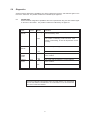
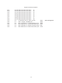
1
CATALOG NO.: 5000.60 B
Effective: 4-09-08
Replaces: 3-15-99
T-2
Raypak B6000 Metasys™ N2
System Protocol Interface
T-2 Communications Interface
Raypak B6000 Boiler Controller
to Johnson Controls Metasys N2 Interface Card
Installation and Operating Manual
P/N 240717 Rev. 3
TABLE OF CONTENTS
1.0 Product Specifications ......................................................................................................................... 3
2.0 Metasys Slave Port Functionality ......................................................................................................... 4
2.1 N2 Slave Communications ....................................................................................................... 4
2.1.1 Command/Replay Cycle ....................................................................................................... 4
2.1.2 N2 System Protocol Comands .............................................................................................. 4
2.1.3 Command Error Checking .................................................................................................... 5
2.1.4 Data Integrity .......................................................................................................................... 5
2.2 N2 Point Layout .................................................................................................................................. 5
3.0 Hardware Setup ................................................................................................................................... 6
3.1 1500 Interface Card Setup ........................................................................................................ 6
3.1.1 Connecting Power to the T-2 Card ........................................................................................ 6
3.1.2 Dip Switch Configuration ....................................................................................................... 6
3.1.3 1500 Jumper Configurations ................................................................................................ 7
3.2 B6000 Communications .................................................................................................................... 7
4.0 N2 System Protocol Support .............................................................................................................. 8
4.1 Attribute Commands ................................................................................................................. 8
4.1.1 Analog Input ........................................................................................................................... 8
4.1.2 Binary Input ............................................................................................................................ 8
4.1.3 Analog Output ......................................................................................................................... 8
4.1.4 Binary Output ......................................................................................................................... 8
4.2 Controls Commands .......................................................................................................................... 8
4.3 Device Identifier Code ......................................................................................................................... 8
5.0 Diagnostics ......................................................................................................................................... 9
5.1 LED Indicatiors ......................................................................................................................... 9
T-2 (Raypak B6000 Metasys N2 System Protocol Interface ..................................................................... 16
T-2 Installation and Mounting .................................................................................................................... 17
Wiring 1500 - RPK ..................................................................................................................................... 18
B6000 System Control Board .................................................................................................................... 19
Wiring: B6000 System Control To Gateway Cable .................................................................................... 20
Check Your Power Source ........................................................................................................................ 20
APPENDICES
Appendix A
Metasys Point Mapping
Appendix B
Communication cable connection diagrams
NOTE: Minimum 18 AWG, 105°C, stranded wire must be used for all low voltage (less than
30 volts) external connections to the unit. Solid conductors should not be used because they
can cause excessive tension on contact points. Install conduit as appropriate. All high voltage
wires must be the same size (105°C, stranded wire) as the ones on the unit or larger.
1.
Product Specifications
The Raypak Gateway card is a hardware product designed to be a communications front end for the Raypak
B6000 Boiler Control and Johnson Controls N2 compatible masters.
The product includes the following functionality:
Metasys N2 Slave Interface
· Binary Input, Binary Output, Analog Input and Analog Output data type commands
supported for primary control/monitoring of the B6000 operating parameters
·
Supported Command/Subcommands:
0/4 :
Poll Message No Acknowledge
0/5 :
Poll Message with Acknowledge
0/9 :
Status Update
1/1 :
Read Analog Input Attributes
1/2 :
Read Binary Input Attributes
1/3 :
Read Analog Output Attributes
1/4 :
Read Binary Output Attributes
2/1 :
Write Analog Input Attributes
2/2 :
Write Binary Input Attributes
2/3 :
Write Analog Output Attributes
2/4 :
Write Binary Output Attributes
7/2/3 :
Override Analog Output
7/2/4 :
Override Binary Output
F :
Identify Device Type
The following commands are recognized, and acknowledged, but do not have impact on
the operation of the Gateway, and do not return any data:
0/0 :
Time Update
0/8 :
Warm Start
All other commands return a Bad Command Error Code
•
Warning and Alarming functions preform on Analog Input and Binary Input data types
•
Change of State Reponse buffering
Raypak B6000 Interface
•
RS-485 electrical interface (as well as RS-232 and RS-422)
•
Emulates Raypak Modem address and functionality
General Specifications
·
Configuration via dip switches
Slave Address, Baud and Parity
Hardware Specifications
·
4"x5" form factor
·
Two male 9-pin D shell connectors
·
Slave communications port configurable for RS-232C or RS-422/485
·
Communication status - Active and Fault for each port
·
9 to 30 VDC external power
3
2.0
Metasys Slave Port Functionality
2.1
N2 Slave Communications
The Comminications Interface card supports the Johnson Controls Metasys™ N2 Protocol, as a slave, on
port 1. This capability allows the module to communicate data from the Raypak B6000 Boiler Control to
a Johnson Controls Metasys Master such as the Johnson Controls Companion™ or Metasys software.
The following discusses the functional capabilities of the card.
2.1.1
Command/Reply Cycle
Successful communications between a Slave and a Master will always consist of the following two
transactions:
Command:
Message from master giving instruction to slave.
Reply:
Response to command.
A slave station will respond to a master issued command in several ways.
Data Message:
If the command was executed by the Slave, the response message will include the
data requested, or an acknowledgment that the command was executed.
Error Message:
If the command could not be executed by the Slave, for whatever reason, an error
response message is transmitted to the master. The error response message contains an error code
indicating the cause of the error.
No Reply:If the master does not detect a reply within its time-out period, the master should retransmit the
command, before a time out error is issued. If the Slave could not decode the message or an error
occurred preventing the Slave from recognizing the message, no response will be issued.
2.1.2
N2 System Protocol Commands
The T-2 supports the commands and the data types necessary to enable control of the B6000 Controller
from an N2 master. The data types and the commands, as well as the associated addressable points are
overviewed below.
Data Types The N2 System protocol treats data as objects, with each data type having a different
structure and purpose. The data types recognized by the T-2 card are as follows:
·
Binary Input
(BI)
·
Binary Output
(BO)
·
Analog Input
(AI)
·
Analog Output
(AO)
Reading Attributes
The data objects contain attributes which describe several data points,
and some of its functionality. The contents of these attributes, including
object configuration, status, current value, and alarm/warning limits, can
be accessed with the following commands:
1/1
1/2
1/3
1/4
Read Analog Input Attributes
Read Binary Input Attributes
Read Analog Output Attributes
Read Binary Output Attributes
4
Writing Attributes
The data object attributes can be configured by a master using the
following commands:
2/1
2/2
2/3
2/4
Write Analog Input Attributes
Write Binary Input Attributes
Write Analog Output Attributes
Write Binary Output Attributes
Controlling the B6000 Controller
Access to the control functions is made available through the Override
commands. The following commands allow the B6000 to be controlled:
7/2/3
7/2/4
Override Analog Output
Override Binary Output
Status Update
The host can issue a ‘Status Update’ command to the T-2. The response will contain device information (“1500-N2 Rev 1.0A”) as well as
current status information.
0/9
Status Update
Identify Device
When a master host first powers up, the ‘Identify Device’ command is
issued to all of the Slaves. In the case of the T-2 card, the Device Code
10 Hex is returned to the host. When the Gateway first powers up, it will
return and error code 0 in response to all commands from the host,
indicating to the host that a power up condition has occurred. The host
will respond with the “Identify Device’ command, telling the Communications Interface that the host has detected the power condition. The command code is:
F
2.2
Identify Device
2.1.3
Command Error Checking
When the Slave cannot execute a command, an error code is generated and returned to
the Master. Error codes generated at the Slave will usually be indicative of an illegal
function, an illegal address, or bad data.
2.1.4
Data Integrity
As in all good protocols, there must exist a level of data integrity checking to verify, with
some degree of assurance, the quality of the transmitted data. The N2 System protocol
supports a summation/modulus type of error checking on the address and data content of
the communication packet.
N2 Point Layout
A relationship between the N2 Point Address and the B6000 parameters has been set up to ease
control and monitoring of the unit. The relationship, by data object type, is shown in detail in
Appendix A.
5
Hardware Setup
3.0
3.1
1500 Interface Card Setup
3.1.1
Connecting Power to the T-2 Card
The T-2 Card requires an external source of DC voltage. The DC source
voltage should be between 9V and 30V. The power is connected to TB1,
located near the two 9 pin serial port connections.
The connection to TB1 is as follows:
TB1-1
9-30 VDC (+)
TB1-2
Common(-)
3.1.2
SW 1
1 2 3 4 5 6 7 8
O
F
F
↓
•
•
Dip Switch Configuration
The T-2 card is configured primarily through two sets of dip switches.
These switches are read initially on power up only.
The function of the dip switches is as follows (a value of one (1) is
registered when the switch is in the ON position):
OFF Position:
• • • • •
•
1 2 3 4 5 6 7 8
SW 2
O
F
F
•
↓
ON Position:
SW1 : Metasys Port Configuration
Switch
Position
Function
1
Baud Rate
2
Selection
3
* Factory Settings
9600, No Parity, Address Bit 1
4
5
Parity
Selection
6
7
8
Not Used
OFF Position:
• • • • • •
•
ON Position:
3
0
0
0
0
1
1
1
1
2
0
0
1
1
0
0
1
1
5
0
0
1
1
4
0
1
0
1
Positions
1
0 300
1 600
0 1200
1 2400
0 4800
1 9600 0 19200
1 19200
None Odd
Even
Invalid
SW2 : Metasys N2 Slave Address Configuration
Switch
Position
Function
Positions
1
Baud Rate
1 Address Bit 0
2
Address
2 Address Bit 1
3
Select
3 Address Bit 2
4
4 Address Bit 3
5
5 Address Bit 4
6
6 Address Bit 5
7
7 Address Bit 6
8
8 Address Bit 7
6
*
*
Value = 1
Value = 2 Value = 4
Value = 8
Value = 16
Value = 32
Value = 64
Value = 128
*
The parameters are defined as follows:
Baud Rate:
The baud rate at which the module is to operate.
The baud rate is configured as follows:
Value
Baud Rate
0
1
2
3
4
5
6
300 Baud
600 Baud
1200 Baud
2400 Baud
4800 Baud
9600 Baud*
19200 Baud
If a value outside of this range is selected,upon firing the power
up process the card’s LEDs will flash on 1/2 second intervals
until a correct address is selected. Powering down is not necessary.
Parity: The parity mode to be used by the module is defined by this word as follows:
0 No parity
1 Odd parity
2 Even parity
Metasys N2 Slave Address: Each of the separate drops off of a Johnson Controls Metasys Host must
have a different Slave address. The Slave address is selected by encoding the Slave address in a binary
form using the
dip switches.
3.1.3
1500 Jumper Configurations
The 1500 Interface card has five sets of jumpers on the board. Generally, the default jumper positions will
be adequate for most applications, with JP4 and JP5 being the only jumpers that should ever need to be reviewed. For
completeness, we provide the following discussion on all of the jumper locations:
JP
1
2
3
4
5
3.2
Discussion
Hardware Reset (Not used)
Isolated Port 2 Power
1-2 Non-Isolated (Default)
2-3 Isolated (Should not be used)
Isolated Port 2 Ground
1-2 Non-Isolated (Default)
2-3 Isolated (Should not be used)
Metasys Port (P1) Termination Resistor
1-2 Connect 120 Ohms across Rec lines
2-3 Disconnect 120 Ohms (Default)
Metasys Port (P1) RS-232 or RS-422/485 Select
1-2 RS-232 Select (Should not be used)
2-3 RS-422/485 Select (Default)
B6000 Communications
The B6000 Communications Interface has been hard coded to operate at the following default conditions:
Baud
9600
Parity
Odd
Stop Bits
1
The 1500 Interface card emulates the modem card that is normally connected to the B6000.
7
4.0
N2 System Protocol Support
The Raypak T-2 card supports several data read and write commands for the N2 System protocol. The
decision on which command to use is made depending on the type of data being addressed, and the level
of protocol support in the master equipment. The following sections detail the different commands supported by the module.
4.1
Attribute Commands
The T-2 Interface card supports the reading and writing to the data object attributes. Although read/
write support is available for all attributes (i.e., the card will accept, store, and respond with values
downloaded from a master), the T-2 does not use all aspects of the attribute functions. The following subsections discuss each data type, and in particular any functional aspects not supported by
the T-2.
4.1.1
Analog Input
The Analog Input data object is by far the most complicated of the objects. All aspects of
warning and alarm logic are supported by the T-2 ( i.e., the T-2 uses the low and high alarm/
warning limits to detect and trigger the object’s alarm bits).
Not supported however are the linear ranging parameters, the filter weight, and the offset.
The presumption is made that all analog input values gathered from the B6000 will come
in scaled. No scaling parameters are required from the master to support any of the
analog input values.
4.2
4.1.2
Binary Input
The Binary Input data object supports the normal state and alarm logic. The debounce and
accumulator attributes are not supported.
4.1.3
Analog Output
The Analog Output data object is used by the T-2 as a simple conduit for set points in the
B6000. No support is provided for scaling the output value, or for verifying the saturation
level of the output value. The value written from the Master is communicated to the Controller.
4.1.4
Binary Output
The Binary Output data object is implemented to respond directly to the commands received from the master. When the master sends an output command, either a bit set or
reset, the command is decoded and communicated to the Controller.
Control Commands
The 1500 card accepts control commands from a Master upon receipt of the following commands:
- Override Analog Output (Command 7/2/3)
- Override Binary Output (Command 7/2/4)
4.3
Device Identifier Code
When the T-2 receives an “Identify Yourself” command, the code 10 Hex is sent to the Master. The
10 Hex is the device ID used by Non-Johnson Controls hardware.
8
5.0
Diagnostics
Several hardware diagnostics capabilities have been implemented using the LED indicator lights on the
front of the 1500 card. The possible conditions as indicated by the lights are:
5.1
LED Indicators
Several hardware diagnostics capabilities have been implemented using the LED indicator lights
on the front of the module. The possible conditions as indicated by the lights are:
NAME
PORT
ACTIVE
Color
Green
Status
Blinking
Indication
The 1500 is receiving a valid response
from the Metasys Host
OFF
The 1500 is not detecting a valid command. If the
master is transmitting, be sure all dip switches are set
correctly.
PORT 2
ACTIVE
Green
Blinking
The 1500 is processing a B6000 command.
PORT 1
COMM
ERR
Red
OFF
ON
Check cable connections
The Metasys port has detected a communications
error condition
PORT 2
FAULT
Red
OFF
ON
No error conditions at this time.
The 1500 card has detected a communications
error condition.
OFF
No error condition as at this time.
Should the configuration dip swicthes select an invalid address or an invalid baud
rate, the LED indicators will alternate in an on/off fashion on 1/2 second intervals
until correct values are selected.
9
APPENDIX A
Metasys Point
Mapping
10
Raypak Controller N2 Registers
Raypak Metasys Register Assignments
Analog
Output
AO1
AO2
AO3
AO4
AO5
AO6
AO7
AO8
AO9
AO10
AO11
AO12
AO13
AO14
AO15
AO16
AO17
AO18
AO19
AO20
AO21
AO22
AO23
AO24
AO25
AO26
AO27
AO28
AO29
AO30
AO31
AO32
AO33
AO34
AO35
AO36
Parm
Offset
28
29
30
31
32
33
34
35
36
37
38
39
40
41
42
43
44
45
46
47
48
49
50
51
52
53
53
54
55
57
160
161
162
163
164
165
Description
Setpoint
Day Setup (Desired water temp @ 70F)
Nitesetpoint Night Setpoing (Desired water temp @ 70F)
Ratio Out
1-200 = 0.1 - 20.0 in 0.1 increments
Throttling
Delta T of all boilers in system
Modulating Step ( % )
Wait State Time (Sec)
Outdoor Cut off temperature
Control Band (degrees F tolerance from TAR)
Lead Boiler Number (1 to Number of Boilers online)
Number of Boilers on line
TP - Boiler Pump Delay (Min) Boiler #1
TP - Boiler Pump Delay (Min) Boiler #2
TP - Boiler Pump Delay (Min) Boiler #3
TP - Boiler Pump Delay (Min) Boiler #4
TP - Boiler Pump Delay (Min) Boiler #5
TP - Boiler Pump Delay (Min) Boiler #6
TP - Boiler Pump Delay (Min) Boiler #7
TP - Boiler Pump Delay (Min) Boiler #8
TS - Boiler Start Times (Sec) Boiler #1
TS - Ignition Time (Sec) Boiler #2
TS - Ignition Time (Sec) Boiler #3
TS - Ignition Time (Sec) Boiler #4
TS - Ignition Time (Sec) Boiler #5
TS - Ignition Time (Sec) Boiler #6
TS - Ignition Time (Sec) Boiler #7
TS - Ignition Time (Sec) Boiler #8
Time - Hrs
Time - Min
Time - DWK
Lead Change Hours
OC Dead band: Off T>)C, ON T<=OC-OC&B
Wait 1: Integral “I” Wait State Time
KPN : Propportional “P” Constant Numerator (0-255)
KPD : Propportional “P” Constant Denominator (0-255)
KDN : Differential “D” Constant Numerator (0-255)
KDD : Differential “D” Constant Denominator (0-255)
Binary
Output
BO1
BO2
Parm
Offset
166
167
Description
Initialize B6000 by writing STAR 80h odh to unit
Setback on/off control (0 = Off, 1 = On) - Write word value to B6000
11
STAR
4025h
Raypak Controller N2 Registers
Raypak Metasys Register Assignments
Analog
Input
AI 1
AI 2
AI 3
AI 4
AI 5
AI 6
AI 7
AI 8
AI 9
AI 10
AI 11
AI 12
AI 13
AI 14
AI 15
AI 16
AI 17
AI 18
AI 19
AI 20
AI 21
AI 22
AI 23
AI 24
AI 25
AI 26
AI 27
AI 28
AI 29
AI 30
AI 31
AI 32
AI 33
AI 34
AI 35
AI 36
AI 37
AI 38
AI 39
AI 40
AI 41
AI 42
AI 43
AI 44
AI 45
AI 46
AI 47
AI 48
AI 49
AI 50
Parm
Offset Description
60
Outdoor Temperature + 35
61
Water Temperature + 35
62
Controller Target Temp
63
Valve Positions (0-100%) - Boiler #1
64
Valve Positions (0-100%) - Boiler #2
65
Valve Positions (0-100%) - Boiler #3
66
Valve Positions (0-100%) - Boiler #4
67
Valve Positions (0-100%) - Boiler #5
68
Valve Positions (0-100%) - Boiler #6
69
Valve Positions (0-100%) - Boiler #7
70
Valve Positions (0-100%) - Boiler #8
79
Setpoint
Day Setup (Desired water temp @ 70F)
80
Niteset
Night Setpoing (Desired water temp @ 70F)
81
Ratio Out
1-200 = 0.1 - 20.0 in 0.1 increments
82
Throttling Delta T of all boilers in system
83
Modulating Step ( % )
84
Wait State Time (Sec)
85
Outdoor Cut off temperature
86
Control Band (degrees F tolerance from TAR)
87
Lead Boiler Number (1 to Number of Boilers online)
88
Number of Boilers on line
89
TP - Boiler Pump Delay (Min) Boiler #1 -Combine w/ seconds registers
90
TP - Boiler Pump Delay (Min) Boiler #2
91
TP - Boiler Pump Delay (Min) Boiler #3
92
TP - Boiler Pump Delay (Min) Boiler #4
93
TP - Boiler Pump Delay (Min) Boiler #5
94
TP - Boiler Pump Delay (Min) Boiler #6
95
TP - Boiler Pump Delay (Min) Boiler #7
96
TP - Boiler Pump Delay (Min) Boiler #8
97
TS - Ignition Time (Sec) Boiler #1
98
TS - Ignition Time (Sec) Boiler #2
99
TS - Ignition Time (Sec) Boiler #3
100
TS - Ignition Time (Sec) Boiler #4
101
TS - Ignition Time (Sec) Boiler #5
102
TS - Ignition Time (Sec) Boiler #6
103
TS - Ignition Time (Sec) Boiler #7
104
TS - Ignition Time (Sec) Boiler #8
105
Time - Hrs
106
Time - Min
107
Time - DWK
108
LEAD CHANGE
109
Hrs Remaining
111/112 Boiler Valve Up Times (Sec) #1
113/114 Boiler Valve Up Times (Sec) #2
115/116 Boiler Valve Up Times (Sec) #3
117/118 Boiler Valve Up Times (Sec) #4
119/120 Boiler Valve Up Times (Sec) #5
121/122 Boiler Valve Up Times (Sec) #6
123/124 Boiler Valve Up Times (Sec) #7
125/126 Boiler Valve Up Times (Sec) #8
12
Raypak Controller N2 Registers
AI 51
AI 52
AI 53
AI 54
AI 55
AI 56
AI 57
AI 58
AI 59
AI 60
AI 61
AI 62
AI 63
AI 64
127/128
129/130
131/132
133/134
135/136
137/138
139/140
141/142
150
151
152
152
153
154
Boiler Valve Down Times (Sec)
#1
Boiler Valve Down Times (Sec)
#2
Boiler Valve Down Times (Sec)
#3
Boiler Valve Down Times (Sec)
#4
Boiler Valve Down Times (Sec)
#5
Boiler Valve Down Times (Sec)
#6
Boiler Valve Down Times (Sec)
#7
Boiler Valve Down Times (Sec)
#8
OC Dead band: Off T>)C, ON T<=OC-OCWait 1 : Integral “I” Wait State Time
KPN : Proportional “P” Constant Numerator (0-25
KPD: Proportional “P” Constant Denominator (0-2
KDN : Differential “D” Constant Numerator (0-255)
KDD: Differential “D” Constant Denominator (0-25
13
4621h
4605h
460bh
460ch
460fh
4610h
extra read registers
Raypak Controller N2 Registers
Raypak Metasys Register Assignments
Binary
Output
Bl 1
Bl 2
Bl 3
Bl 4
Bl 5
Bl 6
Bl 7
Bl 8
Bl 9
Bl 10
Bl 11
Bl 12
Bl 13
Bl 14
Bl 15
Bl 16
Bl 17
Bl 18
Bl 19
Bl 20
Bl 21
Bl 22
Bl 23
Bl 24
Bl 25
Bl 26
B127
Bl 28
Bl 29
Bl 30
Bl 31
Bl 32
Bl 33
Bl 34
Bl 35
Bl 36
Bl 37
Bl 38
Bl 39
Bl 40
Bl 41
Bl 42
Bl 43
Bl 44
Bl 45
Bl 46
Bl 47
Bl 48
Parm
Offset
58/0
59/0
59/1
110/0
71/0
/1
/2
/3
/4
/5
/6
/7
/8
/9
/10
72/0
/1
/2
/3
/4
/5
/6
/7
/8
/9
/10
73/0
/1
/2
/3
/4
/5
/6
/7
/8
/9
/10
74/0
/1
/2
/3
/4
/5
/6
/7
/8
/9
/10
Description
Bit 0 = Night setback present
Bit 0 = Fault Status (1=system fault)
Bit 1 = call Out Request (1 = Yes)
Bit 0 = Setbacl pm) 1_
Boiler Not On Line
OK - Boiler Operation
Low Water outoff
Low Pressure Water
Low Pressure Gas
High Pressure Gas
High Limit
Thermostat - Operating aquastat (not
Manual Override
Flow Switch
No Pilot
Boiler Not On Line
OK - Boiler Operation
Low Water outoff
Low Pressure Water
Low Pressure Gas
High Pressure Gas
High Limit
Thermostat - Operating aquastat (not
Manual Override
Flow Switch
No Pilot
Boiler Not On Line
OK - Boiler Operation
Low Water outoff
Low Pressure Water
Low Pressure Gas
High Pressure Gas
High Limit
Thermostat - Operating aquastat (not
Manual Override
Flow Switch
No Pilot
Boiler Not On Line
OK - Boiler Operation
Low Water outoff
Low Pressure Water
Low Pressure Gas
High Pressure Gas
High Limit
Thermostat - Operating aquastat (not
Manual Override
Flow Switch
No Pilot
14
Night Setback
Controller LED Status
Controller LED Status
Boiler #1
fault)
Boiler #2
fault)
Boiler #3
fault)
Boiler #4
fault)
Raypak Controller N2 Registers
Bl
Bl
Bl
Bl
Bl
Bl
Bl
Bl
Bl
Bl
Bl
Bl
Bl
Bl
Bl
Bl
Bl
Bl
Bl
Bl
Bl
Bl
Bl
Bl
Bl
Bl
Bl
Bl
Bl
Bl
Bl
Bl
Bl
Bl
Bl
Bl
Bl
Bl
Bl
Bl
Bl
Bl
Bl
Bl
50
51
52
53
54
55
56
57
58
59
60
61
62
63
64
65
66
67
68
69
70
71
72
73
74
75
76
77
78
79
80
81
82
83
84
85
86
87
88
89
90
91
92
93
75/0
/1
/2
/3
/4
/5
/6
/7
/8
/9
/10
76/0
/1
/2
/3
/4
/5
/6
/7
/8
/9
/10
77/0
/1
/2
/3
/4
/5
/6
/7
/8
/9
/10
78/0
/1
/2
/3
/4
/5
/6
/7
/8
/9
/10
Boiler Not On Line
OK - Boiler Operation
Low Water outoff
Low Pressure Water
Low Pressure Gas
High Pressure Gas
High Limit
Thermostat - Operating
Manual Override
Flow Switch
No Pilot
Boiler Not On Line
OK - Boiler Operation
Low Water outoff
Low Pressure Water
Low Pressure Gas
High Pressure Gas
High Limit
Thermostat - Operating
Manual Override
Flow Switch
No Pilot
Boiler Not On Line
OK - Boiler Operation
Low Water outoff
Low Pressure Water
Low Pressure Gas
High Pressure Gas
High Limit
Thermostat - Operating
Manual Override
Flow Switch
No Pilot
Boiler Not On Line
OK - Boiler Operation
Low Water outoff
Low Pressure Water
Low Pressure Gas
High Pressure Gas
High Limit
Thermostat - Operating
Manual Override
Flow Switch
No Pilot
Boiler #5
aquastat (not fault)
Boiler #6
aquastat (not fault)
Boiler #7
aquastat (not fault)
Boiler #8
aquastat (not fault)
15
T-2 (Raypak B6000 Metasys N2 System Protocol Interface)
Contents
Quantity
T-2
EPROM (CPX.XNMn) in small black ESD box
1
1
Check packaging for damage or missing components
IMPORTANT NOTICE: These instructions are intended for the use by qualified personnel only, specifically trained
and experienced in the installation of this type of equipment and related system components. Installation and service
personnel may be required by some states to be licensed. If your state is such, be sure your contractor bears the
appropriate license. Only qualified persons shall attempt to repair this equipment.
WARNING: Improper installation, adjustment, alteration, service or maintenance may damage the equipment, create
a hazard resulting in asphyxiation, explosion, fire, electric shock, personal injury or property damage and will void the
warranty.
CAUTION: ONE SUPPLY SOURCE. TO REDUCE THE RISK OF ELECTRIC SHOCK, DISCONNECT ALL CONNECTIONS BEFORE SERVICING.
CAUTION: RISK OF ELECTRIC SHOCK. DISCONNECT SWITCH IS REQUIRED TO DE-ENERGIZE THE EQUIPMENT BEFORE SERVICING.
Thank you for selecting the Raypak B6000 Boiler Management System and the Raypak B6000 Metasys N2 System
Protocol Interface. It is our sincere hope that you will enjoy its power, ease of use and energy saving features.
Please follow the instructions carefully to insure proper installation.
FORWARD
The Raypak Communications Interface is designed to allow the Johnson Controls Metasys System to monitor and
control the Raypak B6000 Boiler Management System.
16
T-2 INSTALLATION AND MOUNTING
T-2 Module should be mounted on a permanent base not subject to vibrations, moisture or dust. It should be readily accessible, for
serviceability.
MECHANICAL INSTALLATION
Mount the System Protocol Interface within five (5) feet of B6000 System Control Box.
The Gateway Interface must be mounted vertically with conduit holes facing downward. Conduit holes are provided to accommodate
standard conduit fittings. Additional or larger conduit fitting that may be required should be located on the bottom of the module. Mount
the Interface with 3/8” or 1/4” hardware in four (4) places.
A Minimum of six (6) inches clearance on all sides is required and a minimum of eighteen (18) inches clearance from the front is required
for service access. The hinged side of the box is to the right and the clearance (minimum 3” from bolt hole on the right
side) should be sufficient to open the cover.
A sub-panel containing the disconnect switches and surge suppressors is required at or near the equipment locations(s).
for accessibility remove the lower interior panel, by removing the four (4) access screws.
INSTALL CONDUIT AS APPROPRIATE.
ELECTRICAL CHARACTERISTICS
120 VAC, 0.25A 60 Hz
ELECTRICAL INSTALLATION
120 VAC FEEDER CIRCUITS
Install a surge protection device sized appropriately for your installation.
Install separate disconnect means for each load. Pull in appropriately sized wire for equipment as defined by NEC
and/or local code.
It is strongly recommended that the Communications Interface B6000 System Control Module and the B6000 Boiler
Control Module be supplied from the same source power.
17
WIRING 1500 - RPK
1.
Open front door of System Protocol Interface Gateway Enclosure.
2.
Remove Four Screws and the lower cover, revealing the field wiring blocks.
3.
Attach wires from Johnson Controls Metasys N2 Interface Card (N2 BUSS) to the field wiring side of left
terminal block (N+, GND, N=, N- GND). Refer to diagram in this user manual.
4.
Turn off power to the B6000 System Control Box.
5.
Open front door of the B6000 System Control Box.
6.
Remove four screws and the lower cover, revealing the field wiring blocks in lower left.
7.
Run RS-485 cable (provided) to the lower left field wiring terminal in the B6000 System Control Box.
Attach wires to the upper four terminals as follows.
BLU/WHT
WHT/BLU
ORG/WHT
SHIELD
to
to
to
to
+
COM
GND
(1)
(2)
(3)
(4)
8.
The EPROM (CPX.XNMn) in small black ESD box, must be installed in place of the current EPROM.
9.
View the B6000 System Control Board picture on the next page. Note Location of the EPROM, U4.
10.
Remove four screws holding upper panel with display screen and keypad. Carefully remove upper panel and
turn over exposing B6000 System Control board.
11.
Using ESD procedures carefully remove EPROM labeled CP80NM to location U4.
12.
Again using ESD procedures carefully replace with EPROM labeled CP80NM to location U4.
13.
Reassemble B6000 System Control Box.
14.
Turn power back on to B6000 System Control Box.
15.
Connect 120 VAC (hot, Neutral, ground) to T-2 at right terminal block.
16.
Reassemble.
18
B6000 SYSTEM CONTROL BOARD
EPPROM, U4
19
CHECK YOUR POWER SOURCE
CIRCUIT BREAKER PANEL
AC 108 Volts AC Minimum, 132 Volts MAX
AB = 108 Volts AC Minimum, 132 Volts MAX
BC = Must be less than 1.0 Volts AC
20
APPENDIX B
Communication Cable
Connection Diagrams
21
22
www.raypak.com
Raypak, Inc., 2151 Eastman Avenue, Oxnard, CA 93030 (805) 278-5300 FAX (805) 278-5489
Litho in U.S. A.