1
TJ/
MODEL NU
-Assembly
,Operation
Customer
Responsibilities
o Service
, Adjustments
- Repair Parts
Caution:
Read and Follow
all Safety Rules
and instructions
Before Operating
This Equipment
917,373680
®
SAFETY RULES
,&o,o.o.
REPAIRS
o
o
PLUG TO PREVENT ACCIDENTAL STARTING WHEN SETTING UP, TRANSPORTING, ADJUST NG OR MAKING
iMPORTANT
SAFETY STANDARDS REQUIRE OPERATOR PRESENCE CONTROLS TO MiNIMiZE THE RmSKOF iNJURY. YOUR UNiT iS EOUIPPED WtTH
SUCH CONTROLS. DO NOT ATTEMPT TO DEFEAT THE FUNCTION OF THE OPERATOR PRESENCE CONTROLS UNDER ANY CtRCUMSTANCES,
TRAINING:
Read this operator's manual carefully. Become famitiar with
the controls and know how to operate your mower property.
Learn how to quickly stop mower,
"
Always stop the engine whenever you leave or are not using
you r mower, or before crossing driveways, walks, roads, and
any gravel-cover_t areas.
,,
Do not atfow children to use your mower. Never altow adutts
to use mower without proper instructions.
=
Never directldischarge of material toward bystanders nor
allow anyone near [he mower while you are operating it.
o
Keep the area of operation ctear of a]t persons, especially
smatl children and pets.
,'
"
Use mower only as the manufacturer
scribed in this manual.
Before cleaning, inspecting, or repairing your mower, stop
the engine and make absolutely sure the blade and all
moving parts have stopped. Then disconnect the spark plug
wire and keep it away from the spark plug to prevent
accidental starting:
e
Do not operate mower if it has been dropped or damaged in
any manner, AIways have damage repaired before using
your mower.
',
Do not continue to run your mower if you hit a foreign object.
Follow the procedure outlined above, then repair any damage before restarting and operating you mower.
Do not use accessory attachments that are not recommended
by the manufacturer,
Use of such attachments may be
hazardous.
,,
Do not change the governor settings or overspeed the
engine. Engine damage or personal injury may result.
,,
Do not operate your mower if it vibrates abnormally. Exces.sive vibration is an indication of damage; stop the engine,
safely check for the cause of vibration and repair as required.
intended and as de-
The blade turns when the engine is running.
PREPARATION:
•*
Do not run the engine indoors.
ous.
Always thoroughly check the area to be mowed and clear it of
all stones, sticks, wires, bones, and other foreign objects.
These objects wilt be thrown by the blade and can cause
severe injury.
Never cut grass by pulling the mower towards you. Mow
across the face of slopes, never up and down or you might
lose your footing. Do not mow excessively steep slopes.
Use caution when operating the mower on uneven terrain or
when changing directions - maintain good footing.
Always wear safety glasses or eye shields when starting and
while using your mower.
"
Dress properly.
Do not operate mower when barefoot or
wearing open sandals. Wear only solid shoes with good
traction when mowing.
'_
Check fuel tank before starting engine. Do not fill gas tank
indoors, when the engine is running or when the engine is hot.
Allow the engine to cool for several minutes before filling the
gas tank. Clean off any spilted gasoline before starting the
engine.
-
Always make:wheel height adjustments before starting your
mower. Never attempt to do this while the engine is running.
,,
Mow only in daylight or good artificial light.
Never operate your mower without proper guards, plates,
grass catcher or other safety devices in place.
MAINTENANCE
OPERATmON:
',
Do not mow wet or slippery grass. Never run while operating
your rnower. Always be sure of your footing - keep a firm ho_d
on the handles and walk.
Do not put hands or feet near or under rotating parts. Keep
clear of the discharge opening at all times.
2
AND STORAGE:
,'
Check the blade and the engine mounting bolts often to be
sure they are tightened properly.
,,
Check all bolts, nuts and screws at frequent intervals for
proper tightness to be sure mower is in safe working condition.
,,
Keep all safety devices in place and working.
,,
To reduce fire hazard, keep the engine free of grass, leaves
or excessive grease and oil.
,,
Check grass catcher often for deterioration and wear and
replace worn bags. Use only replacement bags that are
recommended by and comply with specifications of the
manufacturer of your mower.
,,
Always keep a sharp blade on your mower.
-
Allow engine to cool before storing in any enclosure.
,,
Never store mower with fuel in the tank inside a building
where fumes may reach an open flame or an ignition source
such as a hot water heater, space heater, clothes dryer, etc.
Keep you r eyes and mind on your mower and the area being
cuL Do not let other interests distract you.
,,
Exhaust fumes are danger-
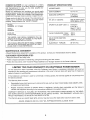
PRODUCT
CONGRATULATIONS
on your purchase of a Sears
Craftsman Lawn Mower, It has been designed, engineered
and manufactured
to give you the best possible dependability and performance.
Should you experience any problems you cannot easily
remedy, please contact your nearest Sears Service CentedDepartment.
Sears has competent, well trained technicians and the proper tools to service or repair this unit.
Please read and retain this manual. The instructions wil!
enable you to assemble and maintain your lawn mower
properly, Always observe the "SAFETY RULES"_
MODEL
NUMBER
917.373680
SPECIFICATIONS
HORSEPOWER:
5.3
DISPLACEMENT:
12.0 cu. in,
GASOLINE CAPACITY:
1.25 quart
(Unleaded)
OIL (20 oz. Capacity):
SAE 30 (Above 32°F)
5W30 (Below 32°F)
SPARK PLUG (GAP .030 in.):
Champion
RJ19LM or
Sears z_ 33312
or STD 361458
VALVE CLEARANCE:
.008 in.
.008 in,
SERIAL
NUMBER
DATE OF
PURCHASE
THE MODEL AND SERIAL NUMBERS WILL BE
FOUND ON A DECAL ATTACHED TO THE REAR
OF THE LAWN MOWER HOUSING.
YOU SHOULD RECORD BOTH SERIAL NUMBER
AND DATE OF PURCHASE AND KEEP IN A SAFE
PLACE FOR FUTURE REFERENCE.
MAINTENANCE
SOLID STATE IGNITION
AIR GAP:
,0125 in.
BLADE BOLT TORQUE:
35-40 ft,-Ibs.
AGREEMENT
A Sears Maintenance
CUSTOMER
Intake:
Exhaust:
Agreement is available on this product. Contact your nearest Sears store for details.
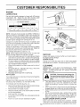
RESPONSIBILITIES
o Read and observe the safety rules.
° Follow a regular schedule in maintaining, caring for and using your lawn mower,
Follow the instructions under "Customer Responsibilities" and "Storage" sections of this OwneCs Manual.
LIMITED TWO YEAR WARRANTY
ON CRAFTSMAN
POWER MOWER
For two years from date of purchase, when this Craftsman Lawn Mower is maintained, lubricated, and tuned up
according to the operating and maintenance instructions in the owner's manual, Sears wilt repair free of charge any
defect in material or workmanship.
If this Craftsman Lawn Mower is used for commercial or rental purposes, this warranty applies for only 90 days from
the date.of purchase.
This Warranty does not cover:
•
Expendable items which become worn during normal use. such as rotary mower blades, blade adapters, belts,
air cleaners and spark plug.
Repairs necessary because of operator abuse or negligence, including ben1 crankshafts and the failure to
maintain the equipment according to the instructions contained in the owneCs manual.
WARRANTY SERVICE IS AVAILABLE BY RETURNING THE CRAFTSMAN
EST SEARS SERVICE CENTER/DEPARTMENT IN THE UN1TED STATES.
WHILE THIS PRODUCT IS IN USE IN THE UNITED STATES.
POWER MOWER TO THE NEARTHIS WARRANTY APPLIES ONLY
This Warranty gives you specific legaf rights, and you may also have other rights which vary from state to state.
SEARS,
ROEBUCK AND CO., D/817 WA, HOFFMAN ESTATES, ILLINOIS 60179
3
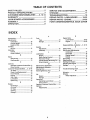
TABLE OF CONTENTS
SAFETY RULES .............................................
2
PRODUCT SPECIFICATIONS
........................ 3
CUSTOMER RESPONSIBILITIES
...... 3, 12-14
WARRANTY
.......... .........................................
3
LAWN MOWER ACCESSORIES
...................
ASSEMBLY
.....................................................
OPERATION
...................................................
SERVICE AND ADJUSTMENTS
.................. 15
STORAGE ..................... :...............................
17
TROUBLESHOOTING
........ ,.......................... .18
REPAIR PARTS- LAWN MOWER ......... 19-23
REPAIR PARTS -ENGINE, ..... ;............... 24-26
PARTS ORDERING/SERVICE.
BACK COVER
5
6
8
iNDEX
A
Accessories ............................................ 5
Adjustments:
Carburetor .................................. 16
Handle Height ............................ 16
Height of Cut ................................ 9
Air Filter:
Service .................................... ;.,,14
Assembly:
Handle ..........................................
6
Grass Catcher .............................. 7
B
Blade:
Sharpening ................................. 13
F_epJacement .............................. 13
C
Controls:
Operator Presence Control Bar .8
Drive Control ................................ 8
Customer Responsibilities ..... 3, 12-14
Air Filter ......................................
14
Blade Care/Replacement
.......... 13
Drive Wheels .............................. 13
Engine ........................................
Gear Case ...................................
Lubrication .................................
Spark Plug .................................
E
14
13
14
14
Engine:
Oil Change .................................
Oil Level .....................................
14
14
Oil Type ......................................
Starting .......................................
Sto rage .......................................
14
10
17
F
Fue!:
Type ............................................
10
Storage ............ ........................... 17
H
Handle:
Adjustment ................................. 16
Assembly ..................................... 6
L
Lubrication:
Engine ........................................
12
Brake Spring Bracket ................ 12
Rear Door Hinge ........................ 12
Handle Bracket Mounting Pin .. 12
Wheel Adjuster .......................... 12
M
Maintenance Agreement .................... 3
Maintenance Schedule ..................... 12
Mowing Tips ...................................... 11
Mulching/Mowing Tips ..................... ! 1
O
Oil:
Engine ........................................
10
Sto rage ....................................... 17
Operation:
Operating Lawn Mower ............... 9
Drive Control ................................ 9
Operator Presence Control Bar ......... 8
Options:
Attachments ................................. 5
P
Repair Parts
Lawn Mower .......................... 19-23
Engine ................................... 24-26
R
Responsibilities,
Customer ..3,
S
12-14
Safety Rules ........................................
Service and Adjustments:
Carburetor ..................................
Drive Belt ...................................
Engine Speed .............................
Handle ........................................
Spark Plug .........................................
Specifications
.....................................
Starting the Engine ...........................
Stopping the Engine ........................
Storage ..............................................
T
Trouble
2
16
15
16
16
14
3
10
10
17
Shooting Chart ................... 18
W
Warranty ..............................................
Wheels:
Wheel Adjusters ..........................
3
8
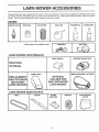
LAWN MOWER ACC
ES
These accessories were available when this lawn mower was produced. They are also available at most Sears retail outlets
and service centers. Most Sears stores can also order repair parts for you, when you provide the modet number of your lawn
mower, Some of these accessories may not apply to your lawn mower.
ENGINE
MUFFLER
SPARK PLUG
AIR FILTER
GAS CAN
ENGINE OiL
STABILIZER
©
if lawn mower is an electric start
I
LAWN MOWER
CHARGER
PERFORMANCE
_
=
7-
=
DUST SHIELD
REAR
CLIPPING DEFLECTOR
BAG
OPTIONAL
SIDE DISCHARGE
FABRIC BAG
OPTIONAL
CATCHER FOR
SIDE DISCHARGE
LAWN MOWER
REPLACEMENT
BAG FOR REAR
DISCHARGE
LAWN MOWERS
LAWN MOWER
BELT
CATCHER
MAINTENANCE
BLADE
BLADE
ADAPTER
/
5
WHEELS
LAWN MOWER
COVER
BL_
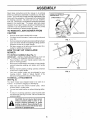
Read these instructions and this manual in its entirety
before you attempt to assemble or operate your new lawn
mower. Your new lawn mower has been assembled at the
factory with the exception of those parts left unassembled
for shipping purposes. All parts such as nuts, washers,
bolts, etc. necessary to complete the assembly have been
placed in the parts bag. To ensure safe and proper
operation of your lawn mower, all parts and hardware you
assemble must be tightened securely. Use the correct
tools as necessary to ensure proper tightnessl
TO REMOVE
CARTON
o
:
¸'
OPERATOR PRESENCE
CONTROLBAR
UPPER HANDLE
LIFT UP
LAWN MOWER FROM
MOWING POSITION
Remove loose parts included with mower.
Cut down two end corners of carton and lay end panel
down flat.
Remove all packing materials except padding between
upper and lower f_andle and 3adding hotding operator
presence control bar to upper handle.
Roll Jawn mower out of carton and check carton thoroughly for additional loose parts.
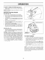
LOWER HANDLE
FIG. 1
SLOTS
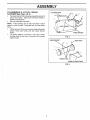
HOW TO SET UP YOUR LAWN
MOWER
TO UNFOLD
HANDLE
(See Fig. 1)
iMPORTANT: UNFOLD HANDLES CAREFULLY SO AS
NOT TO PINCH OR DAMAGE CONTROL CABLES,
*
Raise handles until lower handle section locks into
place in mowing position.
Raise upper handle section into place on lower handle,
remove orotective padding and t_ghten both handle
knobs.
.
Remove handle padding holding operator presence
controi bar to upper handle.
Your lawn mower handle can be adjusted for your
mowing comfort.
Refer to "Adjust Handle" in the
Service and Adjustment section of this manual.
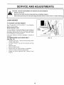
TO iNSTALL
(See Fig. 2)
ATTACHMENTS
Your lawn mower was shipped ready to be used as a
mulcher. To convert to bagging or discharging:
*
Open rear door and remove muicher plate. Store
mulcher plate Jn a safe place.
You can now install catcher or optional clipping deflec[or
To return to mulching operation, install mulcher plate
nto discharge opening of mower. Be sure all tabs are
seated property.
CAUTION: Do not run your lawn mower
without mulcher plate in place or approved clipping
deflector or grass
catcher in place. Never attempt to operate the lawn mower with the rear door
removed or propped open.
f
f
J
/
J
/
J
/
/
MULCHER
PLATE /
FIG. 2
TABS
ASSEMBLY
TO ASSEMBLE
& ATTACH
GRASS
CATCHER
FRAME
CATCHER (See Figs. 3 & 4)
,
•
Put grass catcher frame into grass bag with rigid part of
bag on the bottom. Make sure the frame handle is
outside of the bag top.
Slipvinyl bindings over frame.
NOTE: if vinyl bindings are too stiff, hold them ir warm
water for a few minutes, tf bag gets wet, let it dry before
using.
,
Lift the rear door of the lawn mower and ptace the grass
catcher frame side hooks onto the handle bracket
hooks.
,
The grass catcher is secured to the lawn mower
housing when the rear door is lowered onto the grass
catcher frame,
\
\
FRAME OPENING
FIG. 3
HINGE BRACKET
.*REAR
F
DOOR
RMED TAB
GRASS CATCHER
FIG, 4
FRAME
OPERATION
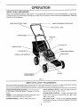
KNOW YOUR
LAWN MOWER
READ THIS OWNER'S MANUAL AND SAFETY RULES BEFORE OPERATING YOUR LAWN MOWER. Compare the
illustrations with your lawn mower to familiarize yourself with the location of various controls and adjustments. Save this
manuai for future reference.
ENGINE ZONE CONTROL
CABLE
OPERATOR
PRESENCE
DRIVE CONTROL
STARTER
CONTROL
BAR
LEVER
HANDLE
CABLE CLIP
GASOLINECAP
GRASS CATCHER
f
PRIMER
MULCHER
ENGINE
OILCAP
_iNE SPEED CONTROL
W/DIPSTICK
/
/
/
DRIVE
COVER
_..
/
WHEEL ADJUSTER
(ON EACH WHEEL)
/
HOUSING
/
-
FIG. 5
MEETS
CPSC SAFETY
REQUIREMENTS
Sears rotary walk-behind power lawn mowers conform to the safety standards of the American National Standards institute
and the U.S. Consumer Product Safety Commission, The blade turns when the engine is running,
OPERATOR PRESENCE CONTROL - must be held down
to the handle to start the engine. Release to Stop the
engine.
DRIVE CONTROL LEVER - used to engage power-propelled forward motion of lawn mower.
PRIMER - pumps additional fuel from the carburetor to the
cylinder for use when starting a cold engine.
engine which allows you to select either fast (,r_) or slow
(,_) engine speed.
STARTER HANDLE - used for starting the eng!ne.
MULCHER PLATE - located at the discharge opening
must be removed when converting to bagging or discharging operation.
ENGINE SPEED CONTROL
- located on the side of the
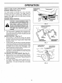
OPERATION
HOW TO USE YOUR
ENGINE
SPEED
LAWN MOWER
(See Fig. 6)
The engine speed is controlled by a
iocated on the side of the engine. Fast
for starting the engine, normal cutting,
bagging. Slow (,_)
position is for light
and fuel economy.
ENGINE
ZONE
ENGINE SPEED
CONTROL
LEVER
lever (red knob)
(_)
position is
and better grass
cutting, trimming
CONTROL
PRIMER
CAUTION: FederaK regulations require
an engine control to be installed on this
FIG. 6
risk of blade contact injury. Do not unlawn mower
in order to attempt
minimizeto the
der.:any
circumstances
defeat tSe function of the operator control
The blade turns: when the engine is
running.
,
Your lawn mower
ence control bar
positioned behind
operate the lawn
DRIVE CONTROL
•
•
,
•
[s equipped with an operator preswhich requires the operator to be
the lawn mower handle to start and
mower.
(See Fig. 7)
DRIVE
CONTROL
Serf-propel!ing is controlled by holding the operator
presence control bar down to the handle and pushing
the drive control lever forward until it clicks; then
release the lever.
Forward motion wilt stop when the operator presence
controt bar is released. To stop forward motion without
stopping engine, release the operator presence control
bar stightty until the drive control disengages. Hold
operator presence control bar down to handle to continue mowing without self-propelling.
To keep drive control engaged when turning corners,
push down on handle and I!ft front wheels off ground
whileturning lawn mower.
TO ADJUST
•
•
OPERATOR PRESENCE
CONTROLBAR
CUTTING
HEIGHT
TO ENGAGE,
DR|VECONTROL
DRIVE
CONTROL
DRIVE CONTROL
DISENGAGED
FIG. 7
LOWER WHEELS
FOR HiGH CUT
RAISE WHEELS
FOR LOW CUT
(See Fig. 8)
Raise wheels for low cut and lower wheels for high cut,
Wheels are set in low cut for shipping. Adjust cutting
height to suit your requirements. Medium position is
best for most lawns.
To change cutting height, Squeeze adjuster lever toward wheel. Move wheel up or down to suit your
requirements.
Be sure all wheels are in the same
setting.
FIG.8
9
OPERATION
-
TO EMPTY
-
GRASS
CATCHER
(See Fig. 9)
Simply lift up rear door and remove the grass catcher
by the handle.
NOTE: Do not drag the bag when emptying; it will cause
unnecessary wear.
BEFORE STARTING
ENGINE
\
'
OIL (See Fig. 10)
Your lawn mower is shipped without oil in the engine.
,
Be sure mower is ]evet and area around oil fill is clean.
,
Remove engine oil cap w/dipstick and fill to the full line
on the dipstick.
Use2Oozs. of oiK For type and grade of oil to use, see
"ENGINE" in Customer Responsibilities section of this
manual.
,
Pour oil slowly. Do not over fill,
Check oit level before each use, Add oil if needed. Fill
to full line on dipstick.
To read proper level, tighten engine oil cap each time,
,
Reinstall engine oil cap and tighten.
= After the first two (2) hours of mowing, change the Oi!,
and every 25 hours thereafter.
You may need to
change the oil more often under dusty, dirty conditions.
ASOLINE FILLER CAP
GAS (See Fig. 10)
-
Fill gasoline tank with fresh, clean, unleaded gasoline.
DO NOT USE PREMIUM GASOLINE, BE CAREFUL
NOT TO OVER FILL TANK.
I
WARNING:
Experience indicates that alcohol blended
fuels (called gasohol or using ethanol or methanol) can
attract moisture which leads to separation and formation of
acids during storage. Acidic gas can damage the fuel
system of an engine while in storage. To _void e0gine
problems, the fuel system should be emptied before storage of 30 days or longer. Drain the fuet tank, start the
engine and let it run until fuel lines and carburetor are
,ompty. Use fresh fuel next season. See Storage tnstruc_,_qs for additional information:
Never use engine or
ct_rburetor cleaner products in fuel tank or permanent
_,t_af_e may occur.
ENGINE OIL CAP
W/DIPSTICK
FIG. 10
TO START
ENGINE
-
To start a cold engine, push 3rimer five (5) times
before trying to start Use a firm push. This step is not
usually necessary when starting an engine which has
already run for a few minutes
-
Push engine speed control lever to fast ('_!_) position.
Hold operator presence control bar down to the handle
and putl starter handle quickly. :3o not allow starter
rope to snap back.
To stop engine, release operator presence control
bar.
-
NOTE: Lncooler weather it may be necessary to repeat
priming steps. In warmer weather over primtng may cause
flooding and engine witl not start. If you do flood engine.
wait a few minutes before attempting to start and do not
repeat priming steps.
10
OPERATION
MOWING
•
•
•
•
•
•
=
TIPS
Under certain conditions, such as very tail grass, it may
be necessary to raise the height of cut to reduce
pushing effort and to keep from overloading the engine
and leaving clumps of grass clippings.
For extremely heavy cutting, reduce the width of cut by
overlapping previously cut path and mow siowiy.
For better grass bagging and most cutting conditions,
the engine speed should be set in the fast (4)
position.
MAX 1/3
When using a rear discharge lawn mower in moist,
heavy grass, clumps of cut grass may not enter the
grass catcher. Reduce ground speed (pushing speed)
and/or run the lawn mower over the area a second time.
FiG. 11
MULCHING
If a trail of clippings is left on the right side of a rear
discharge mower, mow in a clockwise direction with a
Small overlap to collect the clippings on the next pass.
Pores in cloth grass catchers can become filled with dirt
and dust with use and catchers will collect less grass.
To prevent this, regularly hose catcher off with water
and let dry before using.
Keep top of engine around starter clear and clean of
grass clippings and chaff. This will help engine airflow
and extend engine life.
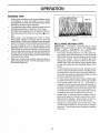
MOWING
TiPS
IMPORTANT:
FOR BEST PERFORMANCE,
KEEP
MOWER HOUSING FREE OF BUILT-UP GRASS AND
TRASH.
SEE
"CLEANING"
IN
CUSTOMER
RESPONSIBILITIES SECTION OF THIS MANUAL.
•
The special mulching blade will recut the grass clippings many times and reduce them in size so that as
they fall onto the lawn they will disperse into the grass
and not be noticed. Also, the mulched grass will
biodegrade quickly to provide nutrients for the lawn.
Always mutch with your highest engine (blade) speed
as this will provide the best recutting action of the
blades.
o
•
•
,
11
Avoid cutting you r lawn when it is wet. Wet grass tends
to form clumps and interferes with the mulching action.
The best time to mow your fawn is the early afternoon.
At this time the grass has dried and the newly cut area
will not be exposed to the direct sun.
For best results, adjust the lawn mower cutting height
so that the lawn mower cuts off only the top one-third
of the grass blades (See Fig. 11). If the lawn is
overgrown it will be necessary to raise the height of cut
to reduce pushing effort and to keep from overloading
the engine and leaving clumps of mulched grass. For
extremely heavy mulching, reduce your width of cut by
overlapping previously cut path and mow slowly.
Certain types of grass and grass conditions may require that an area be mulched a second time to completely hide the clippings. When doing a second cut,
mow across or perpendicular to the first cut path.
Change your cutting pattern from week to week. Mow
north to south one week then change to east to west the
next week. This will help prevent matting and graining
of the lawn.
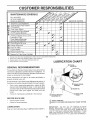
CUSTOMER
MAINTENANCE
RESPONSIBILITIES
SCHEDULE
FILL IN DATES
AS YOU COMPLETE
REGULAR SERVICE
SERVICE
DATES
Check for Loose Fasteners
Clean/Inspect Grass Catcher
(If Equipped)
Clean Lawn Mower
Inspect/Clean Drive Wheels
(Self-Propelled Mowers)
Sharpen/Replace Mower Blade
Lubrication Chart
Clean Battery/Recharge
,)
Check Engine Oil Level
ine Oil
Clean Air Filter
Inspect Muffler
Replace Spark Plug
Replace Air Filter Paper Cartridge
l
2
3
4
-
Change more often when operating under a heav f toad or in high ambient tem_
Service more often when operating tn dirty or dusty conditions.
Replace blades more often when mowing in sanay soil,
Charge 48 hours at end of season.
GENERAL
LUBRICATION
CHART
RECOMMENDATIONS
The warranty on this lawn mower does not cover items that
have been subjected to operator abuse or negligence. To
receive futl vaiuef rom the warranty, operator must maintain
mower as instructed in this manual.
Some adjustments will need to be made periodicatty to
properly maintain your unit.
All adjustments in the Service and Adjustments section of
this manual should be checked at least once each season.
BRAKE SPRING
BRACKET
Once a year, replace the spark plug, replace air filter
element and check blade for wear. A new spark plug
and clean/new air filter element assures proper air-fuel
mixture and helgs your engine run better and last
longer.
Follow the maintenance schedule in this manuat.
BEFORE
o
EACH
"(_ ENGINE
(_
HANDLE BRACKET
MOUNTING PIN
OIL
"(_)REAR
DOOR
HINGE
USE
Check engine oil level.
Check for toese fasteners.
(_
LUBRICATION
Keep unit wetl lubricated (See "LUBRICATION
SPRAY LUBRICANT
(_ REFER TO CUSTOMER RESPONSIBILITIES
"ENGINE"
SECTION.
IMPORTANT:
DO NOT OtL OR GREASE
PLASTIC
WHEEL
BEARINGS.
VISCOUS
LUBRICANTS
WILL
ATTRACT DUST AND DIRT THAT WILL SHORTEN THE
LiFE OF THE SELF LUBRiCATiNG
BEARINGS.
IF YOU
FEEL THEY MUST BE LUBRICATED,
USE ONLY A DRY,
POWDERED GRAPHITE TYPE LUBRICANT
SPARINGLY.
CHART"),
12
CUSTO
LITIES
LAWN MOWER
Always observe safety rules when performing any maintenance.
BLADE
CRANK-
ADAPTER_.
KEYWAY
KEY
-
Keep tires free of gasoline, oil, or insect control chemicals which can harm rubber.
BLADE
Avoid stumps, stones, deep ruts, sharp objects and
other hazards that may cause tire damage.
BLADE
CARE
For best results, mower blade must be kept sharp.
place bent or damaged blades.
Re-
TO REMOVE BLADE (See Fig. 12)
Disconnect spark plug wire from spark plug and place
wire where it cannot come in contact with spark plug.
o Turn lawn mower on its side, Make sure air filter and
carburetor are up.
Use a wood block between blade and mower housing
to prevent blade from turning when removing blade
bott.
,
Piotect you r hands with gloves and/or wrap blade with
heavy cloth;
•
Remove blade bolt by turning counter-clockwise. Use
a 9/16" box or open-end wrench.
•
Remove blade and attaching hardware (bolt, lock
washer and hardened washer).
NOTE: Remove the blade adapter and check the key
inside hub of blade adapter. The key must be in good
condition to work properly. Replace adapter if damaged.
TO REPLACE BLADE (See Fig. 12)
Position the blade adapter on the engine crankshaft.
Be sure key in adapter and crankshaft keyway are
alignedl
= Position blade on the blade adapter aligning the two (2)
holes in the blade with the raised lugs on the adapter.
•
Be sure the 1railing edge of blade (opposite sharp
edge) is up toward the engine.
•
Install the blade bolt with the Iockwasher and hardened
washer into blade adapter and crankshaft.
•
Use block of wood between blade and lawn mower
housing and tighten the blade bolt, turning clockwise.
•
The recommended tightening torque is 35-40 ft. lbs.
IMPORTANT: BLADE BOLT IS GRADE 8 HEAT TREATED.
NOTE: We €Iolnot recommend sharpening blade - but if
you do, be sure the blade is balanced.
HARDENED
WASHER
LOCK WASHER
ADAPTER
•
To keep your drive system working properly, the gear
case and area around the drive should be kept clean
and free of trash build-up. Clean under the drive cover
twice a season.
•
The gear case is filled with lubricant to the proper level
at the factory.
The only time the lubricant needs
attention is if service has been performed on [he gear
case.
If lubricant is required, use only Texaco Starplex Premium Grease, part no. 750355. Do not substitute.
-
DRIVE WHEELS
Check front drive wheels each time before you mow to be
sure theY move freely.
The wheels not turning freely means trash, grass cuttings,
etc. are in the drive wheel area and must be cleaned to free
drive wheels.
If necessary to clean the drive wheels, check both front
wheels.
,
',
o
Remove hubcaps, hairpin cotters and washers.
Remove wheels from wheel adjusters.
Remove any trash or grass cuttings from inside the
dust cover, pinion andtor drive wheel gear teeth.
Put wheels back in place.
If after cleaning, the drive wheels do not turn freely,
contact your nearest authorized service center.
GRASS
=
o
BLADE
GEAR CASE
Care should be taken to keep the blade balanced. An
unbalanced blade wilt cause eventuaf damage to lawn
mower or engine.
The blade can be sharpened with a file or on a grinding
wheel, Do not attempt to sharpen while On the mower.
To check blade balance, drive a nai! into a beam or
wall. Leave about one inch of the straight nail exposed, Place center hole of blade over the head of the
nail. If blade is balanced, it should remain in a
horizontal position. If either end Of the blade moves
downward, sharpen the heavy end until the blade is
13
balanced.
TRAILING
EDGE
FIG. 12
TO SHARPEN BLADE
•
"CRANKSHAFT
BLADE
BOLT
CATCHER
The grass catcher may be hosed with water, but must
be dry when used.
Check your grass catcher often for damage or deterioration. Through normal use it will wear. If catcher
needs replacing, replace only with a manufacturer
approved replacement catcher. Give the lawn mower
model number when ordering.
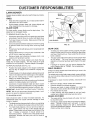
CUSTOME
RESPONSIBILITIES
ENGINE
LUBRiCATiON
Use only high quality detergent oil rated with APt service
classification SG. Select the oil's SAE viscosity grade
according to your expected operating temperature.
SAE V_SCOSITY
GRADES
t
°20 _
.30_
0_
.20 _
TEMPERATURE
60°
q0 _
RANGE
0_
ANtICiPATED
iO o
BEFORE
FIG. 13
80 _
20_
NEXT
30 o
OtL CHANGE
COLLAR
NOTE: Although mufti-viscosity oils (5W30, 10W30 etc.)
improve starting in Cold weather, these multi-viscosity oils
will result in increased oil consumption when used above
32°F. Check your engine oil level more frequently to avoid
possible engine damage from running low on oil.
Change the oil after the first two hours of operation and
every 25 hours thereafter or at least once a year if the lawn
mower is not used for 25 hours in one year.
Check the crankcase oil level before starting the engine
and after each five (5) hours of continuous use. Tighten oil
plug securely each time you check the oil teve!,
TO CHANGE ENGINE OIL (See Fig. 13)
NOTE: Before tipping lawn mower to drain oii, drain fue!
tank by running engine until fue! tank is empty.
•
Disconnect spark plug wire from spark plug and place
wire where it cannot come in contact with spark plug.
o Remove engine oil cap; fay aside on a clean surface.
o Tip lawn mower on its side and drain oil into a suitable
container. Rock lawn mower back and forth to remove
any oil trapped inside of engine.
Wipe off any spilled oil on lawn mower and on side of
engine.
•
Fil! engine with oil. Fill only to the "FULL" line on the
dipstick. DO NOT OVER FILL.
•
Replace engine oil cap.
Reconnect spark plug wire to spark plug.
AIR FtLTER
Your engine will not run properly and may be damaged by
using a dirty air filter.
Replace the air filter every year, more often if you mow in
very dusty, dirty conditions. Do not wash air filter.
TO CHANGE AIR FILTER (See Fig. 14)
o
o
o
Remove the air fiiter €over by turning counterclockwise
to the stop and pull away from collar.
Remove filter from inside of coven
Clean the inside of the cover and the collar to remove
any dirt accumulation.
Insert new filter into cover.
Put air filter cover and filter into collar aligning the tab
with the slot.
-
Push in on cover and turn clockwise to tighten.
TURN
COUNTERCLOCKWISE
TO REMOVE
SLOT
TAB
AIR FILTER COVER
'TO TIGHTEN
FIG. 14
MUFFLER
inspect and replace corroded muffler as it could create a
fire hazard and/or damage.
SPARK
PLUG
Change your spark plug each year to make your engine
start easier and run better. Set spark plug gap at .030 inch.
CLEANING
iMPORTANT:
FOR BEST PERFORMANCE,
KEEP
MOWER HOUSING FREE OF BUILT-UP GRASS AND
TRASH, CLEAN UNDERSIDE OF MOWER HOUSING
AFTER EACH USE,
CAUTIO
from sp_lace
cannot _l:act
wire where it
with the spark
t
plug_
_
Turn lawn mower on its side. Make sure air filter and
carburetor are up. Clean the underside of your lawn
mower by scraping to remove build-up of grass and
trash.
Clean engine often to keep trash from accumulating. A
clogged engine runs hotter and shortens engine life.
,
Keep finished surfaces and wheels free of all gasoline,
oil, etc.
o
We do not recommend using a garden hose to clean
lawn mower unless the electrical system, muffler, air
filter and carburetor are covered to keep water out,
Water in engine can result in shortened engine life.
CLEAN
UNDER DRIVE COVER
Clean under drive cover at least twice a season. Scrape
underside of cover with putty knife or similar tool to remove
14 any build-up of trash or grass on underside of drive cover.
SERVICE AN
CAUTION:
ADJUSTMENTS
BEFORE PERFORMING ANY SERVICE OR ADJUSTMENTS:
Flelease control bar.
,
Make sure the blade and ali moving parts have completely stepped.
o
Disconnect
spark plug wire from spark ptug and place where it cannot come in contact
with ptug,
LAWN MOWER
TO ADJUST
CUTTING
HEHGHT
See "TO ADJUST CUTTING
section of this manual.
HEIGHT" in the Operation
REAR DEFLECTOR
!
The rear deflector,
your lawn mower,
that objects will be
into the operator's
If the rear deflector
replaced_
becomes
TO REMOVE/REPLACE
(See Fig. 15)
.
,,
=
o
,
DRIVE
COVER
attached between the rear wheels of
is provided to minimize the possibility
thrown out the rear of the lawn mower
mowing position.
damaged,
it should
___J
be
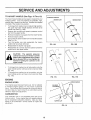
DRIVE BELT
FiG. 15
Remove drive cover, Remove belt by pushing down
on gear case pulley,
Turn lawn mower on its side with carburetor and fuel
cap up.
Remove blade.
Remove debris shield.
Remove belt from engine pulley on crankshaft.
Install new belt by reversing above steps.
Always use factory approved belt to assure fit and
long life.
15
CE
ADJUSTMENTS
_, ,,,.......
TO ADJUST
HANDLE
(See Figs.
16 Thru 18)
SHIPPING
Your lawn mower handle can be raised or lowered for your
mowing comfort. Four (4) positions are available: high,
medium high, medium low and low. Handles are shipped
mounted in the medium low position.
-
*
,
-
,
,
POSITION
MEDIUM LOW
To change from medium low to medium high position,
the upper and tower handle sections wiIl have to be
turned over (See Fig. 16B).
Remove the controls and operator presence control
bar from the upper handle.
Remove the starter rope guide from the lower handle.
Remove hairpin cotters.
Disconnect the lower handle from the handle brackets
(See Fig. 18).
Turr the handle over and reassemble the hairpin
cotters that have been removed.
,,
MEDIUM HIGH
FIG. 16B
FIG. 16A
Reassemble the starter rope guide.
Reassemble the controls and the operator presence
con_rot bar to the upper handle.
LOW
CAUTION:
The operator presence
control bar must pivot freely to permit
blade brake engagement when control
bar is released. Do not over tighten the
fasteners holding the controls to the
upper handle,
•
,
To change from medium
upper handte section witl
Fig. 17A).
To change from medium
lower handle section witl
Fig. !7B).
\
ow to h gh position only the
have to be turned over (See
low to tow position, only the
have to be turned over ',See
FIG. 17A
FIG. 17B
ENGINE
ENGINE
SPEED
LOWER HANDLE
Your engine speed has been factory set. Do not attempt
to increase engine speed or it may result in _ersonal
injury. If you believe that the engine ts running too fast or
too slow take your lawn mower to an authorized service
center for repair and adjustment.
SQUEEZE
TO REMOVE\
CARBURETOR
HANDLE
BRACKET
Your carburetor has a non-adjustable fixed main jet for
mixture control. If your engine does not operate properly
due to suspected carburetor problems, take your lawn
mower to an authorized
service center for repair and
adjustment.
HAIRPIN CLIP
FIG, 18
16
:STORAGE
ENGINE
Immediately prepare your lawn mower for storage at the
end of the season or if the unit will not be used for 30 days
or mere.
FUEL SYSTEM
}MPORTANT:
1T IS IMPORTANT TO PREVENT GUM
DEPOSITS FROM FORMING IN ESSENTIAL FUEL
SYSTEM PARTS SUCH AS CARBURETOR, FUEL FILTER,
FUEL HOSE, OR TANK DURING STORAGE.
ALSO,
EXPERIENCE INDICATES THAT ALCOHOL BLENDED
FUELS (CALLED GASOHOL OR USING ETHANOL OR
METHANOL) CAN ATTRACT MOISTURE WHICH LEADS
TO SEPARATION AND FORMATION OF ACIDS DURING
STORAGE.
ACIDIC GAS CAN DAMAGE THE FUEL
SYSTEM OF AN ENGINE WHILE iN STORAGE.
LAWN MOWER
When lawn mower is to be stored for a period of time, clean
it thoroughly, remove all dirt, grease, ]eaves; etc. Store in
a clean, dry area.
*
Clean entire lawn mower (See "CLEANING" in the
Customer Responsibilities section of this manual).
°
Lubricate as shown in the :Customer Responsibilities
section of this manual.
,
Be sure that a!] nuts, bolts, screws, and pins are
securely fastened. Inspect ' moving parts for damage,
breakage and wear. Replace if necessary.
,
Touch up all rusted or chipped paint surfaces; sand
Iightly before painting.
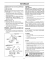
HANDLE
(See Fig. 19)
°
.....
Loosen upper handle mounting bolts enough to allow
upper handle to be folded back.
iMPORTANT: WHEN FOLDING THE HANDLE FOR
STORAGE OR TRANSPORTATION, BE SURE TO FOLD
THE HANDLE AS SHOWN OR YOU MAY DAMAGE THE
CONTROL CABLES.
Never use engine or carburetor cleaner products in the
fuel tank or permanent damage may occur.
o
Use fresh fuel next season.
ENG]INE OIL
.....
Drain oil (with engine warm) and replace with ctean eng'ine
oi!. (See "ENGINE"
in the Customer Responsibilities
section of this manual).
When setting up your handle from the storage position,
the lower handle wilt automatically lock into the mowing position.
CYUNDER
LOWER HANDLE
HANDLE
BRACKET
SQUEEZE
FOLD
-
NOTE:
Fuel stabilizer is an acceptable alternative in
minimizing the formation of fuel gum deposits during storage. Add stabilizer to gasoline in fuel tank or storage
container. Always follow the mix ratio found on stabilizer
container. Run engine at least 10 minutes after adding
stabilizer to allow the stabilizer to reach the carburetor. Do
not drain the gas tank and carburetor if using fuel stabilizer.
Squeeze the bottom ends of the lower handle toward
each other until the lower handle clears the handle
bracket, then move handle forward.
,
*
Drain the fuel tank.
Start the engine and let it run until the fuel lines and
carburetor are empty.
You can fold your lawn mower handle for storage.
°
:
TO
°
Remove spark phJg.
o
Pour one ounce (29 ml) of oi! through spark plug hole
into cylinder.
o
Pull starter handle slowly a few times to distribute oil.
,
Replace with new spark plug.
OTHER
*
HAIRPIN
COTTER
Do not store gasoline from one season to another.
Replace your gasoline can if your can starts to rust.
Rust and/or dirt in your gasoline wi!l cause problems.
o
OPERATOR PRESENCE
CONTROLBAR
If possible, store your unit indoors and cover it to give
protection from dust and dirt.
,
Cover your unit with a suitable protective cover that
does not retain moisture. Do not use plastic. Plastic
cannot breathe which allows condensation to form and
will cause your unit to rust.
IMPORTANT: NEVER COVER MOWER WHILE ENGINE
AND EXHAUST AREAS ARE STILL WARM.
UPPER HANDLE
FOLDFORWARD
FORSTORAGE
FOLD BACKWARD
MOWING
POSITION
l
LOWER HANDLE
FiG. 19
17
with gasoline in the tank inside a bui_tdCAUTION:
ing
where fumes
Never store
may the
reach
lawnanmower
open
flame or spark. Allow the engine to cool
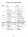
TRO
PROBLEM
LESHOOTi
POINTS
CAUSE
Does not start
Loss of power
CORRECTION
1,
2.
3.
4.
Dirty air filter.
Out of fuel.
Stale fuel
Water in fuel
1,
2.
3.
4.
Clean/replace air fitter.
Fill fuel tank.
Drain tank arid refill with fresh ciean fuel
Drain fuel tank and carburetorand refiII tank with fresh
5.
6.
7.
8.
9.
Spark plug wire is disconnected.
Bad spark plug,
Loose blade or broken blade adapter.
Control bar in released uosition
Control bar defective
5.
6.
7,
8.
9,
gasoline,
Conneetwire topiug.
Replace spark plug.
Tighten blade bolt or replace blade adapter.
Depress control bar to handle,
Replace control bar.
1
Rear of lawn mower housing/blade dragging
in heavy grass.
Cutting too much grass,
Dirty air filter.
Buifdup of grass, leaves and trash under mower,
Too much oitin engine
Watk_ng speed too fast,
1.
Set in "Higher Cut" position,
2,
3.
4.
5.
Set in "Higher Cut" position.
Clean/replace air filter.
Ctean underside of mower housing.
Check oil level,
6.
Cut at slower walking speed.
2.
3.
4.
5.
6.
_
Poorcut*uneven
Excessive
vibration
l
Worn_ bent or loose blade.
2.
3
4.
Wheel heights uneven.
Low engine speed.
BuiiduD of grass, leaves, and trash under mower,
1.
2,
3.
4.
Replace blade, Tighten biade bolt,
Set atI wheels at same height.
Set engine speed control in fast position,
Clean underside of mower housing.
1
2.
Worn, 3ent or loose b_ade.
Bent engine crankshaft.
I,
2,
Reptace blade. Tighten blade bolt,
Contact authorized servioe center/department.
Depress control bar to upper handle before
pulling starter rope,
Contact authorized service center/department.
Replace blade adapter,
Move Iawn mower to cut grass or to hard surface
to start engine.
.
Starter rope hard to pull
Loss of drive
_
-
Grass catcher not filling
(If so equipped)
=
.
.....
_
_=
t
Engine flywheel brake is on when control bar is
released,
1.
2.
3
4
Ben_ engine crankshaft
Blade adapter broken
Blade dragging _ngrass.
2,
3.
4.
1
2.
Drive wheels not turning with drive control engaged
Belt no[ driving
I.
2.
Adiust or replace drive control cable, if broken.
Put belt on pulleys or replace belts if broken.
2.
Cutting height too low,
Lift on blade worn off,
3,
4
Catcher not venting air.
Low engine speed,
t.
2,
3,
4.
Raise cutting height.
Replace biade.
Clean grass catcher.
Set engine speed control in fast position.
=
_L
Hard to push
1
2.
3.
Grass Is too high or wheel height }s too low.
Rear of lawn mower hOUsing/blade dragging
n grass.
Grass catcher too fuIl.
4.
Handle height position not right for you
18
t.
2.
3,
4.
Raise
Raise
setting
Empty
Adjust
cutting height.
rear of lawn mower housing one (1)
higher.
grass catcher.
handle height to suit.
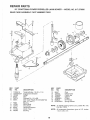
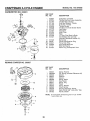
REPAIR PARTS
22" CRAFTSMAN
GEAR CASE
POWER
ASSEMBLY
PROPELLED
PART NUMBER
LAWN MOWER
- - MODEL
NO. 9!7.373680
702511
17
7\
15
10
14
18
13
10
9
7
t9
J
J
J
/
J
jJ
J
J
J
KEY
NO.
PART
NO.
1
2
3
4
5
8
17490416
137055X004
137053
57072
702710
48373
7
8
9
10
11
12
77881
137051
137074
57079
131484
700343
DESCRIPTION
Tapping Screw 1/4-20 x 1-1/4
Engagemem Bracket
Shifter
Seat
Grooved Pin 1/8 x 5/8
Gear Case Halves Kit (includes Key
Nos. 4, 5, and 7)
Bearing
Worm Shaft
Drive Shaft
Hardened Washer
Clutch Yoke
Bushing
19
KEY
NO,
PART
NO.
DESCRIPTION
13
14
15
16
I7
18
19
86447
137050
750436X
750369
12000003
850848
81585X004
Plug
Helical Gear
Ciutch Jaw
Grease
E-Ring
Hi-Pro Key
Spring Bracket
NOTE:
To reseal qousing halves use Locktite No, 515,
Part No. 77923
NOTE:
Ati component dimensions
1 inch = 25.4 mm
g_ven in U.S. inches.
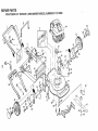
REPAIR PARTS
CRAFTSMAN
22" ROTARY
LAWN
MOWER
1
\
MODEL
NUMBER
917.373680
9
1
27
6
\
3O
14
35
56
56
44
57\
55
29
28
24
3O
REPAIR PARTS
CRAFTSMAN
22" ROTARY
KEY PART
NO. NO
!
2
3
5
6
7
8
9
11
12
14
t5
16
t7
20
21
22
23
24
25
26
27
28
29
30
31
32
34
35
36
133088X479
130861
74350424
85827
136376
STD541425
851509
48137
86344
STD512505
700483X479
700365X479
133190X479
87596X479
128796
133170X479
85543
87677
77400
85179
52160
700781
84921
62335
8502!X004
87877
850855X004
84920
133760
133758
LAWN MOWER
MODEL
NUMBER
KEY PART
NO. NO
DESCRIPTION
Upper Handle
Engine Zone Control Cable
Hex Head Bolt 1/4-20 x 1-1/2
Cable Clip
Handle Knob
Locknut 1/4-20
Control Bar
Rear Door Kit
Self Tapping Screw #10-24
Hex Tapping Screw 1/4-20 x 1/2
Back Plate
Side Baffle
Discharge Baffle
Rear Baffle
Rear Skirt
Mulcher Plate
Engine Pulley
Hi-Pro Key #505
Hubcap
Retainer Clip
Washer
Wheei& Tire Assembly
Shoulder Belt 3/8-t6
Belleville Washer
Axle Arm Assembly
Selector Knob
Selector Spring
Spacer
WheelAdjusting Bracket (Left)
Wheel Adjusting Bracket (Right)
917.373680
t
37
39
40
41
42
43
44
46
47
48
49
50
51
52
55
56
57
58
59
60
61
62
64
_-*
55187
701143X459
701144X459
850998 '
750097
87930
48349
851514
700793
851074
850263
851084
700869X479
85463
751592 :
88652
51793
84676X479
131959
85120tX004
103672X
134612
701544
701581
702452
:
'
DESCRiPTiON
Thread Cutting Screw 5/I6-18 x 3/4
Handle Bracket Assemb{y (Left)
Handie Bracket Assembly (Right)
Hex Head Thread Rolling Screw 3/8,16 x 1-1/8
Hex Washer Head Screw #10-24 x 1/2
Guide Clip
Lawn Mower Housing ({nct. Key #14,15,51 & 52)
Blade Adapter
Blade 22"
Hardened Washer
Heiica] Washer 3/8-24 x 1-3/8 Grd. 8
Hex Head Machine Screw 3/8-24 x 1-3/8 Grd. 8
Front Baffle
Danger Decal
Locknut 3/8-16
Hinge Screw
Hairpin Cotter
Lower Handle
Handle Bolt
Washer
Rope Guide
Debris Shield
Engine - Craftsman - Model No. t43.434332
Owner's Manual (English)
•Owner's Manual (Spanish)
Available accessories not included with lawn mower:
71 33723
High Wheel Kit
Gas Can (2.5 gal.)
Z!33623
Fuel StabiLizer
71 33500
SAE 30W Oil (20 oz.)
71 33300
Dust Shield
Z_!33417
Mower Cover
7_/333t6
Chute Deflector
7!__33303
REPAIR PARTS
CRAFTSMAN
,
y LAWN MOWER MODEL NUMBER 917,37368
22 , ROTAR
....
-
5,4
10
16
!
35
!2
1'o
to
15
-31
10
14
28
41
15
11
8
!3
12
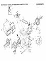
CRAFTSMAN
22" ROTARY LAWN MOWER MODEL NUMBER 917.373680
KEY PART
NO. NO.
1
2
3
4
5
6
7
8
9
10
!t
12
13
14
15
16
18
19
48029
137076
74189
750029
137078
700875
85179
77400
52160
86960
700783
12000057
137054
88080
88118
67725
132800
68038
•
REPAIR PARTS
DESCRIPTION
KEY PART
NO. NO
DESCRIPTION
Drive Head Kit
Drive Control
Locknut #10-24
Pan Head Machine Screw #10-24 x 2
V-Belt
Carriage Bolt 1/4_20 x 2-3/4
Retainer Clip_
Hubcap
Washer
Nylon Bushing
Wheel & Tire Assembly
E-Ring
Pinion
Dust Cover
Felt Washer
Washer 1/2 x 1-1/2 x .134
Selector Knob
Hex Locknut 1/4-20
25
26
27
28
30
31
32
33
34
35
36
37
38
40
4I
52
54
55
56
DriVe Cover Decal
Pan Head Tapping Screw #10-24 x 2-3/4
Hex Washer Head Screw #10-24 x 3/4
Drive Cover
Spacer
Hex Flange Nut
Drive Pulley
DriVe Control Cable Kit
Hi-Pro Key
Wheel Adjuster Assembly (Left)
Gear Case Assembly
Spring
Hex Locknut 1/4-20
Spring
Wheel Adjuster Assembly (Right)
Catcher Frame
Grassbag Assembly
Driveshaft Cover
Screw, Pan Head, Hi-Lo #10-16 x 1/2
702182
87866
750097
700989
77881
132010
137052
48323
850848
751809
702511
137090
STD541425
75192
751810
88614
751663
86012
851552
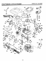
CRAFTSMAN 4..CYCLE ENGINE
i
............
MODEL
NO.143.434332
--
_
263
]
MODELaml
SERIALi_
NUMBERSHERE
/
!19
215
/
4t
45
i
!
204
j
I
182 /
186
/
/
178
24
___
I
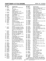
CRAFTSMAN 4..CYCLE ENGINE
REF PART
NO. NO.
t 36265
2
6
7
26727
33734
34214A
8
9
33735
30200
12A
12B
14
15
16
17
18
19
20
30
40
33886
34695
28277
30589
31383A
31335
650548
36281
32600
35801
36073
36074
36075
4!
36070
36071
36072
42
43
45
46
48
50
52
69
70
36076
36077
36078
20381
32875
32610A
27241
35992
29914
35261
34311D
72
73
30572
28833
75
8O
81
82
83
86
89
90
92
93
100
101
!03
27897
30574A
30590A
30591
30588A
650488
611004
611109
650815
650816
34443A
610118
650814
110
1!9
120
125
34961
33554A
34342
29313C
29315C
126 29314B
29315C
DESCRiPTiON
Cylinder Assy, (includes #2 and
20)
Pin, Dowel
Element, Breather
Breather
Assy.(Incl.#6,8,9,12A,12B)
* Gasket, Breather
Screw, Seres, Hex WasherHead,
Self-Tapping #10-24 x 9/16
Tube, Breather
Elbow, Breather Tube
Washer, Flat
Rod, Governor (Includes Ref. #14
Lever, Governor
Clamp, Governor Lever
Screw, Hex Washer #8-32 x 5/16
Spring, Extension
Seal, Oi!
Crankshaft Assembly
Piston, Pin & Ring Assy., Std. Size
Piston, Pin & Ring Assy..010"
Over
Piston. Pin & Ring Assy..020"
Over IAssembfys Include #41.42
and 43)
Piston & Pin Assembly, Std. Size
Piston & Pin Assembly .010" Over
Piston & Pin Assembly .020" Over
(Assemblys Include Reference
#43)
Ring Set. Piston, Standard Size
Ring Set. Piston .010" Oversize
Ring Set. Piston .020" Oversize
Ring, Piston Pin Retaining
Rod Assy. Connecting (Incl. #46)
Bolt. Connecting Rod
Valve. Lifter
Camshaft (Mech. Comp. Release)
Pump Assembly, Oil
* Gasket. Mounting Flange
:lange, Mounting (Includes Ref.
#72.73, 75, 80, 8!, 82 and 83)
Plug, Oil Drain (Includes Ref. #73)
Gasket. Oil Drain Plug
{Not Required with Plastic Oil Plug)
Seal, Oi]
Shaft. Govemor
Washer, Flat
Gear Assy., Governor (Incl. #81)
Spooi. Governor
Screw, Sems. Hex l/4-20 x t-1/4
Key, Flywheel
Flywheel
Washer. Betlevilfe
Nut, Flywheel
Solid State Assembly
Cover. Spark Plug
Screw, Sems. Torx T-15,
Hex Washer Head #10-24 x 1
Wire, Ground
* Gasket. CyIinder Head
Head. Cylinder
Valve. Exhaust, Standard Size
Valve. Exhaust. 1/32" Oversize
Valve. Intake, Standard Size
Valve. Intake, 1/32" Oversize
(All Valves Include Reference
25
#151)
MODEL
NO.143.434332
REF
NO,
130
135
PART
NO,
6021A
35395
DESCRWPTgON
Screw, Hex Flange 5/16-18 x 1-112
Spark Plug, Resistor Type
(Champion RJ-I 9LM or Equivalent)
150 35991
Spring, Valve
151 31673
Cap, Lower Vatve Spring
166 35827
Shroud, Engine
169 27234A
* Gasket, Valve Spring Box
172 32755
Cover, Valve Spring Box
174 650128
Screw, Sems, Hex Hd. #10-24 x 112
t78 29752
Nut and Lock Washer 1/4=28
182 6201
Screw, Hex Cap Head 1/4-28 x 7/8
184 26756
* Gasket, Carburetor
185 31384A
Pipe, Intake (}ncludes Ref. #224)
186 34337
Link, Governor Spring
189 650839
Screw, Sems, Hex Head, Powerlok
1/4-20 x 3/8
190 35831
Lever, Brake
191 35039B
Bracket, S.E. Brake (includes #195)
192 34966
Link, Control
193 34965
Spring, Extension
194 32309
Ring, Retaining
195 610973
Terminal Assembly
200 35727
Bracket Assembly, Control
(Includes Reference #202 thru 205)
202 33802
Spring, Compression
203 31342
Spring, Compression
204 650549
Screw, Fillister Head #5-40 x 7/I6
205 650777
Screw. Fillister Head #6-32 x 21/32
207 34336
Link, Throttle
215 35511
Knob. Control
223 650451
Screw, Sems, Hex Head 1/4-20 x t
224 34690A
* Gasket Intake Pipe
238 650932
Screw, Hex Washer Head,
Shoulder #10-32 x 49/64
239 34338
* Gasket Air Cleaner
241 35797
Collar. Air Cleaner
245 35066
Filter_ Air Cleaner, Paper
250 35065
Cover, Air Cleaner
260 35826
Housing, Blower
262 650831
Screw Hex Washer Head.
Powerlok Thread 1/4-20 x 15/32
263 35821
GriH. Recoil
275 34613A
Muffler Assembly (includes #277)
276 33753
Plate. Lock
277 650795
Screw Hex Head 1/4-20 x 2-1/4
285 35000
Hub, Starter
287 650926
Screw. Hex Washer #8-32 x 2t/64
290 34357
Line Fuel
292 26460
Clamp, Fuel line
300 35586
Tank Assy. ( nct. Nos. 292 and 301 )
301 35355
Cap, Fuel
305 35819A
Tube, Oil Fill
306 34265
* Gasket, Fill Tube
307 35499
"O" Ring
309 650936
Screw, Hex Washer Head.
Shoulder #10-32 × 13/32
310 35822
Dipstick, Oil Fil!
313 34080
Spacer, Flywheel Key
347 650898
Screw. Hex Washer Head.
Shoulder #10-32 x 27/32
370C 35167
Decal, Throttle
380 632681
Carburetor (includes Ref. #184)
390 590637
Starter. Rewind
400 35997
Gasket Set (Inct. items Marked *)
RPM Settings: Low: 2450-2750. High: 2900-3200
*indicates Parts Included in Gasket Set, Reference #400
NOTE: All component dimensions gtven _n U.S. inches
1 inch = 25.4 mm
CRA SMAN
CARBURETOR
4.-CYCLE ENGINE
MODEL
NO.143.434332
NO. 632681
REF PART
NO, NO.
REWIND
STARTER
632681
631615
631767
631184
631183
632504
650506
631775
631867
631024
632019
631028
631021
31
35
35A
40
44
48
631022
36045
632647
632682
27110
631027
Carburetor, Complete
Throttle Shaft and Lever Assembly
Throttle Return Spring
Dust Seat Washer, Throttle
Dust Sea!, Throttle
Throttle Shutter
Throttle and Choke Shutter Screw
Fuel Fitting
Float Bowl
Shaft, Float
Float
"Q" Ring, Float Bowl to Body
Inlet Needle, Seat and Clip
(Includes Reference Number 31)
Spring Clip
Primer Bulb/Retainer Ring
Primer Bulb Filter
High Speed Bowl Nut
Bowl Nut Washer
Welch Ptug, Atmospheric Vent
NO. 590637
®
7
7
REF PART
NO. NO.
DESCRIPTION
_.
1
2
3
4
5
6
7
8
9
10
11
t2
13
Starter; Rewind
Pin, Spring (Includes Reference #4)
Washer
Retainer
Washer
Spring, Brake
Dog, Starter
Spring, Dog
Pulley
Spring, Rewind
Cover; Spring
Housing Assembly, Starter
Rope, Starter (98" Long, 9t64" Dia.)
Handle, Starter
590637
590599A
590600
590615
590601
590598
590616
590617
590618
590619
590620
590638
590535
590452
NOTE: All component dimensions given in U.S, inches
t inch = 25.4 mm
8
6
-1
2
4
5
6
7
16
25
27
28
29
30
DESCRIPTION
6
3
26
SERVICE NOTES
27
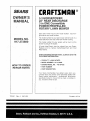
£RAFTIMAN ®
OWNER'S
MANUAL
5.3 HORSEPOWER
22" REAR DISCHARGE
3 in ONE Convertible
POWER PROPELLED
ROTARY LAWN MOWER
Each lawn mower has its own model number,
gine nas tts own model number.
Each en-
The model number for your lawn mower will be found on a
decal attached to the rear of the lawn mower housing.
MODEL NO.
917.373680
The model number for your engine will be found on the
blower housing of the engine,
All parts listedherein
may be ordered from any Sears.
Roebuck and Co, Sewice Center/Department and most
Retail Stores.
WHEN ORDERING REPAIR PARTS, ALWAYS GIVE THE
FOLLOWING _NFORMATION:
- PRODUCT-
LAWN MOWER
® MODEL NUMBER - 917,373680
ENGINE MODELNO.
HOW TO ORDER
REPAIR PARTS
- 143.434332
o PART NUMBER
o PART DESCRIPTION
Your Sears merchandise has added value when you
consider Sears has service units nationwide staffed with
Sears trained technicians..,
professional technicians
specificaliy trained to insure that we meel our pledge to
you, we service what we sell.
701581
I
II
Rev. 4
......
05/11/93
Printed in U.S.A.
I -
II!"'r
I
I
I J
I