1
®
MODEL
917.373231
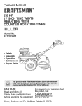
OWNER'SMANUAL
TM
Conv_rt_bm_
° AssembHy
° Operation
o Customer
Responsibilities
° Service
° Adjustments
o Repair Parts
Caution:
Read and Follow
all Safety Rules
and Instructions
Before Operating
This Equipment
SAFETY RULES
REPAIRS.
IMPORTANT
SAFETY STANDARDS REQUIRE OPERATOR PRESENCE CONTROLS
SUCH CONTROLS_
DO NOT ATT'EMPT TO DEFEAT THE FUNCTION
STANCES°
TO MINIMIZE THE RISK OF INJURY. YOUR UNIT IS EQUIPPED WITH
OF THE OPERATOR PRESENCE CONTROLS UNDER ANY CIRCUM-
TRAINING:
•
Read this operator's manual carefully.. Become familiar with
the controls and know how to operate your mower properly.
Learn how to quickly stop mower.
°
Always stop the engine whenever you leave or are not using
your mower, or before crossing driveways, walks, roads, and
any gravel-covered areas.
•
Do not allow children to use your mower. Never allow adults
to use mower without proper instructions
•
Never direct discharge of material toward bystanders nor
allow anyone near tire mower while you are operating it.
•
Keep the area of operation clear of all persons, especially
small children and pets.
•
°
Use mower only as the manufacturer
scnbed in this manual.
Before cleaning, inspecting, or repairing your mower, stop
the engine and make absolutely sure the blade and all
moving parts have stopped. Then disconnect the spark plug
wire and keep it away from the spark plug to prevent
accidental starting.
•
Do not operate mower if it has been dropped or damaged in
any manner., Always have damage repaired before using
your mower:_
•
Do not continue to run your mower if you hit a foreign objecL
Follow the procedure outlined above, then repair any damage before restarting and operating you mower..
•
Do not use accessory attachments that are not recommended by the manufacturer._ Use of such attachments may
be hazardous.
•
Do not change the governor settings or overspeed the
engine_ Engine damage or personal injury may result.
•
Do not operate your mower if it vibrates abnormally. Excessive vibration is an indication of damage; stop the engine,
safely check for the cause of vibration and repair as required.
•
Do not run the engine indoors.. Exhaust fumes are danger-
Be aware that
running
intended and as de-
the mower blade turns when the engine is
PREPARATION:
OUS,,
•
Always wear safety glasses or' eye shields when starting and
while using your mower_
Never cut grass by pulling the mower towards you. Mow
across the face of slopes, never up and down or you might
lose your footing, Do not mow excessively steep slopes..
Use caution when operating the mower on uneven terrain or
when changing directions - maintain good footing.
•
Dress properly. Do not operate mower when barefoot or
wearing open sandals. Wear only solid shoes with good
traction when mowing.
Never operate your mower without proper guards, plates,
grass catcher or other safety devices in place_
MAINTENANCE
"
Always thoroughly check the area to be mowed and clear it
of all stones, sticks, wires, bones, and other foreign objects..
These objects will be thrown by the blade and can cause
severe injury..
°
°
•
Check fuel tank before starting engine. Do not fill gas tank
indoors, when the engine is running or when the engine is hot.
Allow the engine to cool for several minutes before filling the
gas tank.. Clean off any spilled gasoline before starting the
engine.
AND STORAGE:
•
Check the blade and the engine mounting bolts often to be
sure they are tightened properly.
•
Check all bolts, nuts and screws at frequent intervals for
proper tightness to be sure mower is in safe working condition.
•
Always make wheel height adjustments before starting your
mower. Never attempt to do this while the engine is rvnning.
•
Keep all safety devices in place and working
•
Mow only in daylight or good artificial light
•
To reduce fire hazard, keep the engine free of grass, leaves
or excessive grease and oil
•
Check grass catcher often for deterioration and wear and
replace worn bags. Use only replacement bags that are
recommended by and comply with specifications of the
manufacturer of your rnower_.
•
Always keep a sharp blade on your mower.
•
Allow engine to cool before storing in any enclosure.
•
Never store mower with fuel in the tank inside a building
where fumes may reach an open flame or an ignition source
such as a hot water heater, space heater, clothes dryer, etc.
OPERATION:
•
Keep your eyes and mind on your mower and the area being
cuL Do not let other interests distract you.
o
Do not mow wet or slippery grass.. Never run while operating
your mower. Always be sure of your footing- keep a firm hold
on the handles and walk.
Do not put hands or feet near or under rotating parts. Keep
clear of the discharge opening at all times.
....................................................
LOOK FOR THIS SYMBOL
IT MEANSATTENTION!!!
, ,,,, ,,,,,,,,,
TO POINT OUT IMPORTANT
BECOME ALERT!!!
YOUR
2
SAFETY
PRECAUTIONS.
SAFETY IS INVOLVED,
CONGRATULATIONS
on your purchase of a Sears
Craftsman Lawn Mower_ It has been designed, engineered
and manufactured to give you the best possible dependability and performance_
Should you experience any problems you cannot easily
remedy, please contact your nearest Sears Service CentedDepartment.
Sears has competent, welt trained technicians and the proper tools to service or repair this unit.
Please read and retain this manual.. The instructions wilt
enable you to assemble and maintain your lawn mower
properly. Always observe the "SAFETY RULES'L
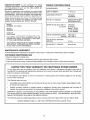
MODEL
NUMBER
PRODUCT
917,373231
SPECIFICATIONS
HORSEPOWER:
5.0
DISPLACEMENT:
11 ..57 cue in,,
GASOLINE CAPACITY:
1o6 quarts
(Unleaded)
OIL (20 ozo Capacity):
SAE 30 (Above 32°F)
5W30 (Below 32°F)
SPARK PLUG (Gap ..030 ino):
(0_76 mm)
Champion
RJ19LM or
Sears zt 33312
or STD 361458
or STD 360950
VALVE CLEARANCE:
°005-°007 ino
o007-_009 in.
SERIAL
NUMBER
DATE OF
PURCHASE
THE MODEL AND SERIAL NUMBERS WILL BE
FOUND ON A DECAL ATTACHED TO THE REAR
OF THE LAWN MOWER HOUSING,.
YOU SHOULD RECORD BOTH SERIAL NUMBER
AND DATE OF PURCHASE AND KEEP IN A SAFE
PLACE FOR FUTURE REFERENCE,.
MAINTENANCE
SOLID STATE IGNITION
AIR GAP:
o010 in,.
BLADE BOLT TORQUE:
35-40 ft.-Ibs_
AGREEMENT
A Sears Maintenance
CUSTOMER
intake:
Exhaust:
Agreement is available on this producL
Contact your nearest Sears store for details.
RESPONSIBILITIES
= Read and observe the safety rules..
• Follow a regular schedule in maintaining, caring for and using your lawn mower.
= Fo]fow the instructions under "Customer Responsibilities"
LIMEED
TWO YEAR WARRANTY
and "Storage" sections of this Owner's Manual
ON CRAFTSMAN
POWER MOWER
For two years from date of purchase, when this Craftsman Lawn Mower is maintained, lubricated, and tuned up
according to the operating and maintenance instructions in the owner's manual, Sears will repair free of charge any
defect in material or workmanship.
If this Craftsman Lawn Mower is used for commercial or rental purposes, this warranty applies for only 90 days
from the date of purchase,_
This Warranty does not cover:
•
Expendable items which become worn during normal use, such as rotary mower blades, blade adapters, belts,
air cleaners and spark plug.
°
Repairs necessary because of operator abuse or negligence, including bent crankshafts
maintain the equipment according to the instructions contained in the owner's manual.
and the failure to
WARRANTY SERVICE IS AVAILABLE BY RETURNING THE CRAFTSMAN POWER MOWER TO THE NEAREST SEARS SERVICE CENTERIDEPARTMENT
IN THE UNITED STATES. THIS WARRANTY APPLIES ONLY
WHILE THIS PRODUCT IS IN USE IN THE UNITED STATES_
This Warranty gives you specific legal rights, and you may also have other rights which vary from state to state.
SEARS, ROEBUCK AND CO.., D/817 WA, HOFFMAN ESTATES, ILLINOIS 60179
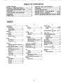
TABLE OF CONTENTS
SAFETY RULES .............................................
2
PRODUCT SPECIFICATIONS
........................ 3
CUSTOMER
RESPONSIBILITIES
...... 3, 12-14
WARRANTY ....................................................
3
LAWN MOWER ACCESSORIES
................... 5
ASSEMBLY .....................................................
6
OPERATION
...................................................
8
SERVICE AND ADJUSTMENTS
.................. 15
STORAGE .....................................................
18
TROU B LESHOOTING ..................................
19
REPAIR PARTS - LAWN MOWER ......... 20-24
REPAIR PARTS - ENGINE ...................... 25-30
PARTS ORDERING/SERVICE.
BACK COVER
mNDEX
A
Accessories ............................................. 5
Adjustments:
Carburetor .................................. 17
Handle Height ............................ 16
Height of Cut ................................ 9
Air Filter:
Service ........................................
14
Assembly:
Handle ..........................................
6
Grass Catcher .............................. 7
B
Blade:
Sharpening ................................. 13
Replacement .............................. 13
C
Controls:
Operator Presence Control Bar .8
Drive Control ................................ 8
Customer Responsibilities
..... 3, 12-14
Air Filter ......................................
14
Blade Care/Replacement
.......... 13
Drive Wheels .............................. 13
Engine ........................................
14
Gear Case ...................................
13
Lubrication ................................. 12
Spark Plug ..................................
E
Engine:
Oil Change .................................
Oil Level .....................................
Oil Type ......................................
Starting .......................................
Storage .......................................
14
14
14
14
10
18
P
F
Fuel:
Type .............................................
Storage .......................................
10
18
H
Repair Parts
Lawn Mower ..........................
Engine. ..................................
R
Responsibilities,
20-24
25-30
Customer .... 3, 12-14
S
Handle:
Adjustment .................................. 16
Assembly ........................................ 6
L
Lubrication:
Safety Rules ........................................
See,ice and Adjustments:
Carburetor'. .................................
Drive Belt ...................................
17
15
Engine ........................................
12
Rear Door Hinge ......................... 12
Handle Bracket Mounting Pin .. 12
Wheel Adjuster .......................... 12
M
Engine Speed ............................
Handle ........................................
17
16
Maintenance Agreement .................... 3
Maintenance Schedule ..................... 12
Mowing Tips ...................................... 11
Mulching/Mowing Tips ..................... 11
O
Oil:
Engine ........................................
14
Storage .......................................
18
Operation:
Operating Lawn Mower'. .............. 9
Drive Control ................................ 9
Operator Presence Control Bar ..... ;..8
Options:
Attachments ................................. 5
4
Spark Plug .........................................
Specifications .....................................
Starting the Engine ..........................
Stopping the Engine ........................
Storage ..............................................
2
14
3
10
10
18
T
Trouble Sirooting Chart ................... 19
W
Warranty ..............................................
Wheels:
Wheel Adjusters ..........................
3
8
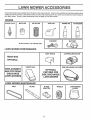
These accessories were available when this lawn mowerwas produced _They are also available at most Sears retail outlets,
catalog and service centers_ Most Sears stores can also order repair parts for you, when you provide the model number of
your lawn mower° Some of these accessories may not apply to your lawn mower.
ENGmNE
SPARK PLUG
AIR FILTER
MUFFLER
GAS CAN
CHARGER
ENGINE OIL
STABILIZER
BATTERY
if lawn mower is an electric start
LAWN MOWER
PERFORMANCE
DUST SHIELD
CUPPING DEFLECTOR
REAR BAG
OPTIONAL
FABRIC BAG
REPLACEMENT
BAG FOR REAR
DISCHARGE
LAWN MOWERS
SIDE DISCHARGE
CATCHER
OPTIONAL
CATCHER FOR
SIDE DISCHARGE
LAWN MOWER
t
LAWN P/lOWER MAINTENANCE
,=,ljl ill
.......
BELT
BLADE
BLADE
ADAPTER
%
5
LAWN MOWER
COVER
Read these instructions and the Operator's Manual in its
entirety before you attempt to assemble or operate your
new lawn mower.. Your new lawn mower has been assernbled at the factory with the exception of those parts left
unassernbled for shipping purpose& To ensure safe and
proper operation of your lawn mower, all parts and hardware you assemble must be tightened securelyv Use the
correct tools as necessary to ensure proper tightness. All
parts such as nuts, washers, bolts, etc., necessary to
complete the assembly have been placed in the parts bag
TO REMOVE
CARTON
°
•
•
OPERATOR PRESENCE
CONTROLBAR
UPPER HANDLE
LIFT UP
LAWN MOWER FROM
MOWING POSITION
Remove loose parts included with mower.
Cut down two end corners of carton and lay end panel
down flat..
Remove all packing materials except padding between
upper and lower handle and padding holding operator
presence control bar to upper handle_
Roll lawn mower out of carton and check carton thoroughly for additional loose parts.
LOWER HANDLE
FIG. 1
SLOTS
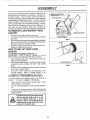
HOW TO SET UP YOUR LAWN
MOWER
TO UNFOLD
HANDLE
(See Fig. 1)
IMPORTANT:
UNFOLD HANDLE CAREFULLY SO AS
NOT TO PINCH OR DAMAGE CONTROL CABLES
o Raise handles until lower handle section locks into
place in mowing position.
o Raise upper handle section into place on lower handle,
remove protective padding and tighten both handle
knobs..
°
Remove handle padding holding operator presence
control bar to upper- handle.,
•
Your lawn mower handle can be adjusted for your
mowing comfort,
Refer to "Adjust Handle" in the
Service and Adjustment section of this manual,
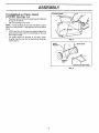
TO INSTALL
ATTACHMENTS
MULCHER
FIG, 2
(See Fig. 2)
Your lawn mower" was shipped ready to be used as a
mulchero To convert to bagging or discharging:
•
•
°
PLATE
Open rear door and remove mulcher plate, Store
rfiulcher plate in a safe place..
You can now install Latchetor optional clipping deflector',
To return to mulching operation, install mulcher plate
into discharge opening of mower_ Be sure all tabs are
seated properly,
CAUTION: Do not run your lawn mower
without mulcher plate in place or approved clipping deflector or grass
catcher in place, Never attempt to operate the lawn mower with the rear door
removed or propped open.
6
TABS
ASSE
TO ASSEMBLE
& ATTACH
CATCHER
(See Figs. 3-4)
o
°
BLY
CATCHER FRAME
GRASS
Put grass catcher frame into grass bag with rigid part
of bag on the bottom.
Slip vinyl bindings over frame.
\
NO'[E: If vinyl bindings are too stiff, hold them in warm
water for a few minutes If bag gets wet, let it dry before
using.
o
-
Lift the rear door on the mower housing and place the
grass catcher frame onto the formed tabs on the rear
door hinge bracket_
The grass catcher is secured to the lawn mower
housing when the rear door is lowered onto the grass
catcher frame.
FIG. 3
/
HINGE
BRACKET
_._
REAR DOOR
FORMED
TABS
GRASS CATCHER
FIG. 4
7
FRAME
OPERATION
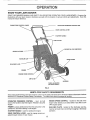
KNOW YOUR LAWN MOWER
READ THIS OWNER'S MANUAL AND SAFETY RULES BEFORE OPERATING YOUR LAWN MOWER. Compare the
illustrations with your lawn mower' to familiarize yourself with the location of various controls and adjustments. Save this
manual for future reference_
ENGINE ZONE CONTROL
CABLE
OPERATOR
PRESENCECONTROLBAR
DRIVE CONTROL
STARTER
LEVER
HANDLE
CABLE CLIPS
ENGINE OIL CAP W/DIPSTICK
GRASSCATCHER
GASOLINE
MULCHER
CAP
DRIVE COVER
PLATE
PRIMER
ENGINE
SPEED CONTROL
AIR FILTER
HOUSING
WHEEL ADJUSTER
(ON EACH WHEEL)
FIG. 5
,_llllll
.................................
MEETS
CPSC SAFETY
REQUIREMENTS
Sears rotary walk-behind power lawn mowers conform to the safety standards of the American National Standards Institute
and the U_S_Consumer Product Safety Commission. The blade turns when the engine is running.
_J
iLi
i ii i i i
lllll
,i,
i::ll:u,
OPERATOR PRESENCE CONTROL
- must be held
down to the handle to start the engine., Release to stop the
engine.
ENGINE SPEED CONTROL
- located on the side of the
PRIMER - pumps additional fuel from the carburetor to the
cylinder for use when starting a cold engine_
MULCHER PLATE - located at the discharge opening,
must be removed when converting to bagging or discharge
operation,
engine which allows you to select either fast (,r_) or' slow
(,_) engine speed.
STARTER HANDLE - used for starting the engine°
DRIVE CONTROL LEVER - used to engage power-propelled forward motion of lawn mower..
8
OPERATION
:, ,llll,l,llll:
lllll,l,,ll,i, ill,,
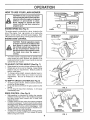
HOW TO USE YOUR LAWN MOWER
ENGINE SPEED
CAUTION: Do not run your lawn mower
without mtdcher plate in place and door
closed orwithout an approved clipping
deflector or grasscatcher
in place.
Never attempt to operate the lawn
mower with the rear door removed or
propped openf
ENGINE
SPEED
(See Fig. 6)
The engine speed is controlled by a lever located on the
side of the engine. Fast (,_) position is for starting the
engine, normal cutting, and better grass bagging. Slow
(-_) position is for light cutting, trimming and fuel economy.
ENGINE
FIG. 6
LOWER WHEELS
FOR HIGH CUT
RAISE WHEELS
FOR LOW CUT
ZONE CONTROL
CAUTION: Federal regulations require
an engine control to be installed on this
lawn mower in order to minimize the
risk of blade contact injury, Do not under any circumstances attempt to defeat the function of the operator control.
The blade turns when the engine is
running,
o
Your lawn mower is equipped with an operator presence control bar which requires the operator to be
positioned behind the lawn mower handle to start and
operate the lawn mower..
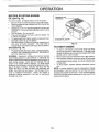
TO ADJUST
=
o
•
•
°
°
o
(See Fig. 7)
GRASS
CATCHER
(See Fig. 8)
To remove grass catcher, release operator presence
control bar to stop engine.
Lift up rear door and remove the grass catcher by the
handle°
Do not drag the bag when emptying;
it will cause
unnecessary wear.
DRIVE CONTROL
=
HEIGHT
Raise wheels for low cut and lower wheels for high cut
Wheels are set in low cut for shipping.. Adjust cutting
height to suit your requirements. Medium position is
best for most lawns..
To change cutting height, squeeze adjuster lever toward wheel
Move wheel up or down to suit your
requirements.. Be sure afl wheels are in the same
setting,
TO EMPTY
•
CUTTING
FIG. 7
FIG. 8
\
(See Fig. 9)
Self-propelling is controlled by holding the operator
presence control bar down to the handle and pushing
the drive control lever forward until it clicks; then
release the lever..
Forward motion will stop when the operator presence
control bar is retease& To stop forward motion without
stopping engine, release the operator presence control
bar slightly until the drive control disengages,
Hold
operator presence control bar down to handte to continue mowing without self-propelling..
To keep drive control engaged when turning corners,
push down on handle and lift front wheels off ground
while turning lawn mower.
OPERATOR PRESENCE
CONTROL BAR
DRIVE
CONTROL
DRIVE CONTROL
FIG. 9
9
OPERAON
BEFORE STARTONG ENGItNE
ENGINE OIL CAP
W/DIPSTICK
OIL (See Fig. 10)
Your lawn mower is shipped without oil in the engine°
.
Be sure mower is level and area around oif fill is clean_
o
Remove engine oi! cap w/dipstick and fill to the full line
on the dipstick_
•
Use 20 ozs. of oi!. For type and grade of oi! to use, see
"ENGINE" in Customer Responsibilities section of this
manual,
o
Pour oil siowly_ Do not over fill,,
°
Check oil level before each user Add oil if needed,, Fill
to full line on dipstick,
° To read proper level, tighten engine oil cap each timev
°
Reinstall engine oil cap and tighten..
•
After the first two (2) hours of mowing, change the oil,
and every 25 hours thereafter_ You may need to
change the oil more often under dusty, dirty conditions.
GASOLINE
FIG. 10
TO START ENGINE
GAS (See Fig. 10)
°
FILLER CAP
°
Fill gasoline tank with fresh, clean, unleaded gasoline.
DO NOT USE PREMIUM GASOLINE. BE CAREFUL
NOT TO OVER FILL TANK..
WARNING:
Experience indicates that alcohol blended
fuels (called gasohol or using ethanol or methanol) can
attract moisture which leads to separation and formation of
acids during storage° Acidic gas can damage the fuel
system of an engine while in storage. To avoid engine
problems, the fuel system should be emptied before storage of 30 days or longer.. Drain the fuel tank, start the
engine and let it run until fuel lines and carburetor are
empty. Use fresh fuel next season. See Storage Instructions for' additional inforrnation_ Never use engine or
carburetor cleaner products in fuel tank or permanent
damage may occur,,
.
=
°
To start a cold engine, push pnmer three (3) times
before trying to start. Use a firm push, This step is not
usualty necessary when starting an engine which has
already run for a few minutes.
Move engine speed control lever to fast (,_) position_
Hold operator presence control bar down to the handle
and pull starter handle quickly_, Do not allow starter' rope
to snap back.
To stop engine, release operator' presence control
bar.
NOTE: In cooler weather it may be necessary to repeat
priming steps. In warmerweather over priming may cause
flooding and engine will not start. If you do flood engine,
wait a few minutes before attempting to start and do not
repeat priming steps,,
10
OPERATIO
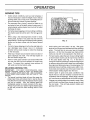
MOWING
o
TraPS
Under certain conditions, such as very tall grass, it
may be necessary to raise the height of cut to reduce
pushing effort and to keep from overloading the engine and leaving dumps of grass clipping&
°
For extremely heavy cutting, reduce the width of cut
and raise the rear of the lawn mower housing one (1)
wheel adjuster setting higher than the front for better
discharge of grass.
o
For better grass bagging and most cutting conditions,
the engine speed should be set in the fast (,_) position°
o
When using a rear discharge lawn mower in moist,
heavy grass, clumps of cut grass may not enter the
grass catcher. Reduce ground speed (pushing speed)
and/or run the lawn mower over the area a second
time°
•
•
°
MAX 1/3
FIG. 11
If a trail of grass clippings is ieft on the right side of a
rear discharge lawn mower, mow in a clockwise
direction with a small overlap to collect the clippings
on the next pass°
Keep top of engine around starter clear and clean of
grass clippings and chaff. This will help engine air
flow and extend engine life.
°
•
Pores in cloth grass catchers can become filled with
dirt and dust with use and catchers will collect less
grass. To prevent this, regularly hose catchers off
with water and let dry before using°
MULCHING
MOWING
TIPS
IMPORTANT,'
FOR BEST PERFORMANCE,
KEEP
MOWER HOUSING FREE OF BUILT-UP GRASS AND
TRASH. CLEAN AFTER EACH USE.. SEE "CLEANING"
IN CUSTOMER RESPONSIBILITIES SECTION OF THIS
MANUAL.
°
The special mulching blade will recut the grass clippings many times and reduce them in size so that as
they fall onto the lawn they will disperse into the grass
and not be noticed.. Also, the mulched grass will
biodegrade quickly to provide nutrients for the lawn..
Always mulch with your highest engine (blade) speed
as this will provide the best recutting action of the
blades.
°
,
11
Avoid cutting your lawn when it is wet. Wet grass
tends to form clumps and interferes with the mulching
action.. The best time to mow your lawn is the early
afternoon. At this time the grass has dried and the
newly cut area will not be exposed to the direct sun°
For best results, adjust the lawn mower cutting height
so that the lawn mower cuts off only the top one-third
of the grass blades (See Fig° 11). If the lawn is
overgrown it will be necessary to raise the height of cut
to reduce pushing effort and to keep from overloading
the engine and leaving clumps of mulched grass. For
extremely heavy mulching, reduce your width of cut,
mow slowly and raise the rear of the lawn mower one
wheel adjuster setting higher than the front.
Certain types of grass and grass conditions may
require that an area be mulched a second time to
completely hide the clippings.. When doing a second
cut, mow across or perpendicular to the first cut path..
Change your cutting pattern from week to week. Mow
north to south one week then change to east to west
the next week. This will help prevent matting and
graining of the lawn_
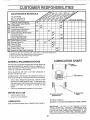
CUSTOMER
ESIPONSH ILHTI
MAI.TENA.CE
SC,EDULE
FILL IN DATES
_:k_ _,_1 _ _,
YOU
Clean/inspect
(If Equipped)
X
°
cubi-icat_on
Cha_
E
N
Check Eng,i,ne Oil Level
Change Engine Oil
G
clean Air Filter
Inspect Muffler
Replace Spark P!ug
__
.
Change
Service
Replace
Charge
......
.
6/'........
I
I
..................
U
U
....
6/
6/ ..........
6/4
6/
,,..
:
_
........
''":':'.".'.'."."."."i
....
......
_2 .....
Replace Air Filter Paper Cartridge
-
_'-o
.......................
A
Clean Batte ry/R ecii,_rge
(Electric Start Mowers)
t
2
3
4
_,,
Grass Ca'{'cher
_..........
, ...................H64_ 6/
Inspect/Clean
Diive Wheels
Clean Lawn Mower'
'.............
(Self-Propelled Mowers)
R sharpeniRepiace
MoWerBiade
N
,-4,
more often when operating under a heavy load or in high ambient lemperatures,
more often when operating in dirty or' dusty conditions,,
blades more often when mowing in sandy soil
48 hours at end of season.
GENERAL
LUBRaCATUON CHART
RECOMMENDATIONS
"]:.hewarranty on this lawn mower does not cover items that
have been subjected to operator abuse or' negligence. To
receive full value from the warranty, operator must maintain
mower as instructed in this manual.
Some adjustments will need to be made periodically to
properly maintair! your unit..
All adjustments in the Service and Adjustments section of
this manual should be checked at least once each season°
o
o
Once a year, replace the spark plug, replace air filter
element and check blade for wear_ A new spark plug
and clean/new air filter element assures proper air-fuel
mixture and helps your engine run better and last
longer..
Follow the maintenance schedule in this manual.
BEFORE
=
o
EACH
USE
(_) HANDLE BRACKET
MOUNTING PIN
Check engine oil level..
Check for loose fasteners..
(_) SPRAY LUBRICANT
LUBRICATION
Keep unit wet! lubricated (See "LUBRICATION
(_) REAR DOOR
HINGE
(_) REFER TO CUSTOMER RESPONSIBILITIES
"ENGINE" SECTION.
CHART").
IMPORTANT:
DO NOT OIL OR GREASE
PLASTIC
WHEEL
BEARINGS.
VISCOUS
LUBRICANTS
WILL
ATTRACT DUST AND DIRT THAT WILL SHORTEN THE
LIFE OF THE SELF LUBRICATING
BEARINGS,. IF YOU
FEEL THEY MUST BE LUBRICATED,
USE ONLY A DRY,
POWDERED GRAPHITE TYPE LUBRICANT SPARINGLY.
12
CUSTOM
ESPO
IL[['IES
II
,i,1,,i,
i1,1,,
ii,
,,,
ii ....
i
,
LAWN MOWER
CRANK_
SHAFT &
BLADE
ADAPTER
DETAIL
BLADE
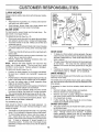
Always observe safety rules when performing any maintenance.
TIRES
o
o
Keep tires free of gasoline, oil, or insect control chemicals which can harm rubber°
TRAILING
EDGE
HARDENED
ADAPTER
Avoid stumps, stones, deep ruts, sharp objects and
other hazards that may cause tire damage.
KEY
BLADE CARE
For best results, mower blade must be kept sharp.,
place bent or damaged blades..
ReCRANKSHAFT
TO REMOVE BLADE (See Fig., 12)
.
o
o
°
•
•
_]_[
Disconnect spark plug wire from spark plug and place
wire where it cannot come in contact with spark plug,,
Turn lawn mower on its side. Make sure air filter and
carburetor are up,,
Use a wood block between blade and mower housing
to prevent blade from turning when removing blade
boil
CRANKSHAFT
KEYWAY
TO REPLACE BLADE (See Fig., 12)
.
Position the blade adapter on the engine crankshaft.
Be sure key in adapter and crankshaft keyway are
aligned°
Position blade on the blade adapter aligning the two (2)
holes in the blade with the raised lugs on the adapter.
•
Be sure the trailing edge of blade (opposite sharp
edge) is up toward the engine.
o Install the blade bott with the lock washer and hardened
washer into blade adapter and crankshaft,
•
Use block of wood between blade and lawn mower
housing and tighten the blade bolt, turning clockwise.
•
The recommended tightening torque is 35-40 ft. Ib&
IMPORTANT: BLADE BOLT IS GRADE 8 HEATTREATED.
•
To keep your drive system working properly, the gear
case and area around the drive should be kept clean
and free of trash build-upo Clean under the drive cover
twice a season.
•
The gear case is filled with lubricant to the proper level
at the factory. The only time the lubricant needs
attention is if service has been performed on the gear
case.
°
If lubricant is required, use only Texaco Starplex Premium Grease, part no.. 750355.. Do not substitute.
DRIVE WHEELS
Check front drive wheels each time before you mow to be
sure they move freely,
The wheels not turning freely means trash, grass cuttings,
etc., are in the drive wheel area and must be cleaned to free
drive wheel&
If necessary to clean the drive wheels, check both front
wheels,
°
•
o
blade - but if
•
•
TO SHARPEN BLADE
Remove hubcaps, hairpin cotters and washers°
Remove wheels from wheel adjusterso
Remove any trash or grass cuttings from inside the
dust cover, pinion and/or drive wheel gear teeth°
Putwheels back in place,.
If after cleaning, the drive wheels do not turn freely,
contact your nearest service center.,
GRASS
Care should be taken to keep the blade balanced. An
unbalanced blade will cause eventual damage to lawn
mower or engine.,
.
BLADE ADAPTER
GEAR CASE
NOTE: Remove the blade adapter and check the key
inside hub of blade adapter., The key must be in good
condition to work properly. Replace adapter if damaged,
°
LOCK WASHER
FIG, 12
Protect your hands with gloves and/or wrap blade with
heavy cloth,,
Remove blade bolt by turning counter-clockwise., Use
a 9/16" box or open-end wrench,
Remove blade and attaching hardware (bolt, lock
washer and hardened washer),
NOTE: We do not recommend sharpening
you do, be sure the blade is balanced°
BLADE
BOLT
•
•
The biade can be sharpened with a rite or on a grinding
wheel° Do not attempt to sharpen while on the mower.
To check blade balance, drive a nail into a beam or
wall., Leave about one inch of the straight nail exposed° Place center hole of blade over the head of the
nail. If blade is balanced, it should remain in a
horizontal position,, If either end of the blade moves
downward, sharpen the heavy end until the blade is
balanced,,
13
CATCHER
The grass catcher may be hosed with water, but must
be dr,,,when used,.
Check your grass catcher often for damage or deterioration. Through normal use it will wear_. If catcher
needs replacing, replace only with a manufacturer
approved replacement catcher. Give the lawn mower
model number when ordering.
ESPONSU mLmTJE$
CUSTO
ENGUNE
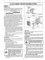
LUBRICATION
Use only high quality detergent oil rated with API service
classification SG. Select the oil's SAE viscosity grade
according to your expected operating temperature.
SAE VISCOSITY
GRADES
CONTAINER
_F
"20°
0_
3o°
°c .___3o0.='oo .loo
TEMPERATURE
RANGE
a2° 40"
_°
ANTICIPATED
60°
;0_
BEFORE
_0°
_oo
100° ,
30°
40"
FIG. 13
NEXT OIL CHANGE
NOTE: Although multi-viscosity oils (5W30, 10W30 etc,,)
improve starting in cold weather, these multi-viscosity oi]s
will result in increased oil consumption when used above
32°Fo Check your engine oit level more frequently to avoid
possible engine damage from running low on oil,,
Change the oil after-the first two hours of operation and
every 25 hours thereafter or at least once a year if the lawn
mower is not used for 25 hours in one year.
Check the crankcase oil level before starting the engine
and after each five (5) hours of continuous use. Tighten oil
plug securely each time you check the oil level_
TO CHANGE ENGINE OIL (See Fig. 13)
.
Disconnect spark plug wke from spark plug and place
wire where it cannot come in contact with spark plug,
•
Remove engine oil cap; lay aside on a clean surface,,
o Tip lawn mower' on its side and drain oil into a suitable
container, Rock lawn mower back and forth to remove
any oil trapped inside of engine,,
o, Wipe off any spilled oil on lawn mower and on side of
engine.
Fill engine with oil. Fill only to the "FULL" line on the
dipstick. DO NOT OVER FILL.
•
Replace engine oil cap,
•
Reconnect spark plug wire to spark plug,
BACK PLATE
CARTRIDGE
LIP
3OVER
TABS
COVER
SCREW
FIG. 14
MUFFLER
Inspect and replace corroded muffter as it could create a
fire hazard and/or damage.
SPARK
PLUG
Change your spark plug each year to make your engine
start easier and run better.. Set spark plug gap at .030 inch.
CLEANaNG
AIR FILTER
IMPORTANT:
FOR BEST PERFORMANCE,
KEEP
MOWER HOUSING FREE OF BUILT*UP GRASS AND
TRASH., CLEAN UNDERSIDE OF MOWER HOUSING
AFTER EACH USE.
Your engine will not run properly and may be damaged by
using a dirty air' filter,,
Replace the air fiiter every year, more often if you mow in
very dusty, dirty conditions,,
TO CLEAN AIR FILTER (See Fig,, 14)
°
Loosen screw and tilt cover to remove,,
•
Carefully remove cartridge,.
•
Clean by gently tapping on a flat surfacer If very dirty,
replace cartridge or clean as follows: Wash in a low or
non-sudsing detergentandwarmwatersotution.
Rinse
thoroughly with flowing water from mesh side until
water runs clear, Let cartridge airdry thoroughly before
using.
i i ,i
,..nr'.r,
I ill
inln
ill
n.nn
CAUTION: Disconnect Spark plug wire
from spark plug and place wire where it
cannot come in contact with the spark
plug.
i,
°
°
CAUTION:
Petroleum solvents, such
as kerosene, are not to be used to clean
cartridge. They may cause deterioration of the cartridge.
Do not oil cartridge. Do not use pressurized air to
clean or dry cartridge.
°
..........................
CLEAN
install cartridge, then replace cover making sure the
tabs are aligned with the slots in the back plate. Fasten
screw securely.
14
......................
ii
Turn lawn mower on its side, Make sure air' fifter and
carburetor are up, Clean the underside of your lawn
mower by scraping to remove build-up of grass and
trash.
Clean engine often to keep trash from accumulating, A
clogged engine runs hotter and shortens engine life,
Keep finished surfaces and wheels free of all gasoline,
oil, etc.
We DO NOT recommend using a garden hose to clean
lawn mower' unless the electrical system, muffler', air
filter and carburetor are covered to keep water out.
Water in engine can result in shortened engine life.
UNDER
DRIVE COVER
Clean under drive cover at least twice a season. Scrape
underside of cover with putty knife or similar tool to remove
any build-up of trash or grass on underside of drive cover,
SERVICE
CAUTION:
,
BEFORE PERFORMING ANY SERVICE OR ADJUSTMENTS:
Release control bar.
Make sure the blade and all moving parts have completely stopped.
,
Disconnect spark plug wire from spark plug and place where it cannot come in contact with plug.
LAWN MOWER
TO ADJUST
CUTTING
See "TO ADJUST CUTTING
section of this manual..
HEIGHT
HEIGHT" in the Operation
m
REAR DEFLECTOR
DRIVE
COVER
The rear deflector, attached between the rear wheels o!
your lawn mower, is provided to minimize the possibility
that objects will be thrown out the rear of the lawn-mower
into the operator's mowing position,.
if the rear deflector
replaced.
becomes
TO REiVIOVE/REPLACE
damaged,
DRIVE
it should
i|
IL
be
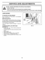
FIG. '15
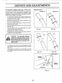
BELT
(See Fig. 15)
°
.
°
o
o
o
Remove drive cover,, Remove bett by pushing down
on gear case pulley,,
Turn lawn mower on its side with carburetor and fuel
cap up
Remove blade,
Remove debris shield,
Remove belt from engine pulley on crankshaft,,
Install new belt by reversing above steps,,
Always use factory approved belt to assure fit and
long life_
15
SERVICE AND ADJUSTMENTS
TO ADJUST
HANDLE
SHIPPING
(See Figs. 16 Thru 18)
MEDIUM LOW
Your fawn mower handle can be raised or lowered for' your
mowing comfort.. Four (4) positions are available: high,
medium high, medium low and low. Handles are shipped
mounted in the medium low position_
o
°
o
o
°
o
°
.
POSITION
To change from medium iow to medium high position,
the upper and lower handle sections will have to be
turned over (See Fig. 16B).
Remove the controls and operator presence control
bar from the upper handle,,
Remove the starter rope guide from the lower handle,
Remove hairpin cotters_
Disconnect the lower handle from the handle brackets
(See Fig° 18).
Turn the handle over' and reassemble the hairpin
cotters that have been removed°
MEDIUM HIGH
FIG. 16B
FIG. 16A
Reassemble the starter rope guide°
Reassemble the controls and the operator presence
control bar to the upper handte_
................
ill
ill
,
'
LOW
.......
HIGH
CAUTION:
The operator presence
control bar must pivot freely to permit
blade brake engagement when control
bar is released. Do not over tighten the
fasteners holding the controls to the
upper handle.
°
•
To change from medium
upper handle section will
Fig 17A).
To change from medium
lower handle section will
Fig° 17B)o
\
\
\
low to high position only the
have to be turned over (See
tow to low position, onty the
have to be turned over (See
FIG. 17A
FIG. 17B
LOWER HANDLE
SQUEEZE
TO REMOVE
HANDLE
BRACKET
HAIRPIN
CLIP
FIG. 18
16
ENGINE
ENGINE
SPEED
TOP NO
LOAD
SCF
Your engine speed has been factory set,. Do not attempt
to increase engine speed or it may. result in personal
injury. If you believe that the engine is running too fast or
too slow, take your lawn mower to an authorized service
center for repair and adjustment°
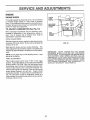
TO ADJUST
CARBURETOR
IDLE SPEED
ADJUSTING
SCREW
(See Fig. 19)
Minor carburetor adjustments may be required to compensate for differences in fuel, temperature, altitude or
load,. The air cleaner and air cleaner cover must be
assembled to carburetor when running.
IDLE
MIXTURE
SCREW
INITIAL ADJUSTMENTWith the engine not running, gently turn idle mixture screw
clockwise until it just closes. Screw may be damaged by
turning it in too far..
FIG. 19
Next open the screw one turn counter-clockwise.
This
initial adjustment will permit the engine to be started and
warmed up (approximately 5 minutes) prior to final adjustmenL
IMPORTANT:
NEVER TAMPER
WITH THE ENGINE
GOVERNOR,
WHICH IS FACTORY
SET FOR PROPER
ENGINE SPEED OVERSPEEDING
THE ENGINE ABOVE
THE FACTORY
HIGH
SPEED
SETTING
CAN BE
DANGEROUS,
IF YOU THINKTHE
ENGINE-GOVERNED
HfGH SPEED NEEDS ADJUSTING,
CONTACT
YOUR
NEAREST
AUTHORIZED
SERVICE
CENTER,
WHICH
HAS PROPER
EQUIPMENT
AND EXPERIENCE
TO
MAKE ANY NECESSARY
ADJUSTMENTS,,
NOTE: Do not adjust top no load adjusting screw_ It was
pre-set at the factory..
FINAL ADJUSTMENTPlace engine speed control lever in idle or slow (,_.)
position° Adjust idle RPM by turning idle speed adjusting
screw to obtain 1700 RPM Next, turn idle mixture screw
in (clockwise -.lean mixture) until engine just starts to slow,
Then turn idle mixture screw out (counter-clockwise - rich
mixture) until engine runs unevenly.. Now turn idle mixture
screw midway between rich and leano Engine should
accelerate smoothly, If engine does not accelerate properly, the carburetor should be readjusted, usually to a
richer mixture, by turning the idle mixture screw counterclockwise 1/8 turn more.
17
STORAGE
ENGINE
Immediately prepare your lawn mower for storage at the
end of the season or if the unit will not be used for 30 days
or more.
FUEL SYSTEM
IMPORTANT:
IT tS IMPORTANT TO PREVENT GUM
DEPOSITS FROM FORMING IN ESSENTIAL
FUEL
SYSTEM PARTS SUCH AS CARBURETOR, FUEL FILTER,
FUEL HOSE, OR TANK DURING STORAGE.
ALSO,
EXPERIENCE INDICATES THAT ALCOHOL BLENDED
FUELS (CALLED GASOHOL OR USING ETHANOL OR
METHANOL) CAN ATTRACT MOISTURE WHICH LEADS
TO SEPARATION AND FORMATION OF ACIDS DURING
STORAGE.
ACID1C GAS CAN DAMAGE THE FUEL
SYSTEM OF AN ENGINE WHILE IN STORAGE..
LAWN MOWER
When lawn mower is to be stored for a period of time, clean
it thoroughly, remove all dirt, grease, leaves, etc. Store in
a clean, dry area.
o
Clean entire lawn mower (See "CLEANING" in the
Customer Responsibilities section of this manual).
o
Lubricate as shown in the Customer' Responsibilities
section of this manual..
•
Be sure that ail nuts, bolts, screws, and pins are
securely fastened.. Inspect moving parts for damage,
breakage and wear'. Replace if necessary.
°
Touch up all rusted or chipped paint surfaces; sand
lightly before painting..
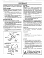
HANDLE
(See Fig. 20)
You can fold your lawn mower handle for storage.
°
Drain the fuel tank,
•
Start the engine and let it run until the fuel lines and
carburetor are empty°
•
Never use engine or carburetor cleaner products in the
fuel tank or permanent damage may occur.
o
Use fresh fuel next season,,
NOTE:
Fuel stabilizer is an acceptable alternative in
minimizing the formation of fuel gum deposits during storage. Add stabilizer' to gasoline in fuel tank or storage
container. Always follow the mix ratio found on stabilizer
container. Run engine at least 10 minutes after' adding
stabilizer to allow the stabilizer to reach the carburetor, Do
not drain the gas tank and carburetor if using fuel stabilizer,.
Squeeze the bottom ends of the lower handle toward
each other until the lower handle clears the handle
bracket, then move handle forward.
o
Loosen upper handle mounting bolts enough to allow
upper' handle to be folded back.
IMPORTANT:
WHEN FOLDING THE HANDLE FOR
STORAGE OR TRANSPORTATION, BE SURE TO FOLD
THE HANDLE AS SHOWN OR YOU MAY DAMAGE THE
CONTROL CABLES
°
=
ENGINE
OIL
Drain oil (with engine warm) and replace with clean engine
oil
(See "ENGINE"
in the Customer Responsibilities
section of this manual).
When setting up your handle from the storage position,
the lower handle will automatically lock into the mowing position.
CYLINDER
LOWER HANDLE
HANDLE
BRACKET
SQUEEZETO
FOLD
o
Remove spark plug,.
•
Pour one ounce (29 rnl) of oil through spark plug hole
into cylinder.
•
Pull starter handle slowly a few times to distribute oil,,
•
Replace with new spark plug,
OTHER
HAIRPIN
COTTER
OPERATOR PRESENCE
CONTROLBAR
°
Do not store gasoline from one season to another,
*
Replace your gasoline can if your can starts to rust,
Rust and/or dirt in your gasoline will cause problems°
o
If possible, store your unit indoors and cover it to give
protection from dust and dirt.
°
Cover your unit with a suitable protective cover' that
does not retain moisture,. Do not use plastic, Plastic
cannot breathe which allows condensation to form and
will cause your unit to rust.
IMPORTANT: NEVER COVER MOWER WHILE ENGINE
AND EXHAUST AREAS ARE STILL WARM
UPPER HANDLE
FOLDFORWARD
FOR STORAGE
FOLD BACKWARD
MOWING
POSITION
CAUTION: Never store the lawn mower
with gasoline in the tank inside a building where fumes may reach an open
flame or spark. Allow the engine to cool
before storing in any enclosure,
LOWER HANDLE
FIG. 20
18
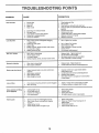
TROUBLESHOOTING
CORRECTION
CAUSE
PROBLEM
Does not start
Loss of power
1.,
2.
3
4
Dirty air filter
Out offue{
Stale fuel..
Water in fuel
1
2
3
4
Cfean/replace air filter
Fill fuel tank
Drain tank and refill with fresh clean fuel
Drain fuel tank and carburetorand refill tank with fresh
5.
6.,
7.
8
9
Spark plug wire is disconnected
Bad sparkpIug
Loose blade or broken blade adapter..
Control bar in released position
Control bar defective
5,.
6.
7
8
9
gasoline
Connect
Replace
Tighten
Depress
Reptace
1.
Rear of lawn mower housing/blade dragging
in heavy grass°
Cutting too much grass
Dirty air filter
Buildup of grass, leaves and trash under mower.
Too much oil in engine.
"
Walking speed too fast
1.
Set in "Higher Cut" position
2.
3
4
5
Set in "Higher Cut" position
Clean!replace air filter,
Clean underside of mower housing
Check oilleveL
6
Cut at slower walking speed,
Worn, bent or toose blade
Wheet heights uneven
Low engine speed
Buildup of grass, leaves, and trash under mower.
t
2,
3.,
4.
Replace blade. Tighten blade bott
Set all wheels at same height.
Set engine speed control in fast position
Clean underside of mower housing.
I
Worn, bent or loose biade
2
Bent engine crankshaft
t,
2
Replace blade, Tighten blade bolt,
Contact authorized service center/department
Depress control bar to upper hand[e before
pulling starter rope
Contact authorized service center/department.
Replace blade adapter,
Move Eawn mower to cut grass or to hard surface
to start engine
2.
3
4
5
6
wire to plug..
spark plug.
blade boJt or replace blade adapter
control bar tohandle,
control bar.
ii ,i
Poor OUt - uneven
t,
2,
3
4.
I'I'IIH
Excessive
vibration
i illll illl,,i,l,ii
,H,i,i,i,i,i
1.
Engine flywheel brake is on when control bar is
reieased
1,
2
3
4.
Bent engi_e crankshaft
Biade adapter broken
Blade dragging in grass
2..
3.
4
Loss of drive
1
2.
Drive wheels not turning with drive control engaged
Belt not driving
1
2
Adjust or replace drive control cable, if broken..
Put belt on pulleys or replace belts if broken
Grass catcher not filling
(If so equipped)
t
2
Cutting height too low
Lift on btade worn off
3
4
Catcher not venting air.
Low engine speed.
1,.
2.
3
4.
Raise cutting height
Replace blade
Clean grass catcher
Set engine speed control in fast position
1
2
Grass is too high or wheel height is too low.
Rear of lawn mower housing/blade dragging
in grass.
Grass catcher too full.
Handle height position not right for you
1.
2,
Raise cutting height
Raise rear of lawn mower housing one (1)
setting higher
Emptygrass catcher
Adjust handle height to suit.,
Starter rope hard to pull
Hard to push
3.
4.
19
3
4
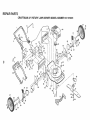
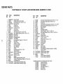
RIEPAnR PARTS
CRAFTSMAN
22" ROTARY LAWN MOWER
MODEL NUMBER
917.373231
8
25
31
6
!1
12
35
28
29
14
67
56
12
I
32
55
Po
c:>
15
!6
20
44
37
68
3t
66
35
52
47
53
27
41
26
34
29
28
51
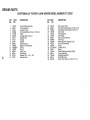
REPAnR PARTS
CRAFTSMAN
KEY
NO.
ro
PART
NO
1133088X479
2 130861
3 74350424
4133170X479
5 85827
6136376
7 STD541425
8 851509
9 48137
1186344
12 STD512505
14 700483X479
15 700365X479
16 133190X479
1787596X479
18 86344
20128796
2284596
23 87677
25 83923
2657143
2788017
28 84921
29 61651
30 750913X004
3187877
32 700331X004
3484920
35 700375
3755187
38 88348
39 701t43X459
40 701144X459
22" ROTARY
LAWN MOWER
MODEL
DESCRIPTION
KEY
NO.
Upper Handle
Engine Zone Control Cable
Hex Head Screw 1/4-20 x 1-1/2
Mulcher Plate
Cable Clip
Handle Knob
Locknut 1/4-20
Control Bar
Rear Door Kit
Self Tapping Screw #!0-24 x 5/8
Hex Tapping Screw wiSems 1/4-20 x 1/2
Back Plate
Side Baffle
Discharge Baffle
Rear Baffle
Hex Head Self-Tapping #10-24 x 1/2
Rear Skirt
Engine Pulley
Hi-Pro Key #505
Hex Flange Nut
Wave Washer
Wheel
Shoulder Bolt 3/8-16 x 1-3/8
Spring Washer
Axle Arm Assembly
Selector Knob
Selector Spring
Spacer
Wheel Adjusting Bracket (Left)
Thread Cutting Screw w!Seres 5/16-18 x 3/4
Flat Washer 3/8
Handle Bracket Assembly (Left)
Handle Bracket Assembly (Right)
41850998
42 750097
43 87930
44 48364
45 83253
46 851514
47752234
48851074
49 850263
50 851084
51 700869X479
52 85463
53 STD523707
55 751592
56 88652
5751793
58 84676X479
59
131959
60 851201X004
61
103672X
62134612
64 700796
66
67
68
---
PART
NO
700170X459
700172X459
86969
702553
701853
NUMBER
917.373231
DESCRIPTION
Hex Head Thread Roiling Screw 3/8-16 x 1-1/8
Hex Washer Head Screw #10-24 x 1/2
Guide Clip
Lawn Mower Housing (Incl. Key #t4, 15, 51 & 52)
Self-Tapping Screw w/Sems 5/16-18 x !-1/2
Blade Adapter
Blade 22"
Hardened Washer
Helical Washer 3/8-24 x 1-3/8 Gr. 8
Hex Head Machine Screw 3/8-24 x 1-3/8 Gr. 8
Front Baffle
- Danger Decal
Hex Bolt 3/8-16 x 3/4
Locknut 3/8-16
Hinge Screw 1/4-20 x 1-!/4
Hairpin Cotter
Lower Handle
Handle Bolt
Washer
Rope Guide
Debris Shield
Engine-Briggs & Stratton Model No. 126802,
Type 3215-01
Bracket Support (Right)
Bracket Support (Left)
Spacer
Owner's Manual (English)
Owner's Manual (Spanish)
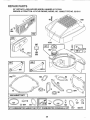
Available accessories not included with lawn mower:
7_.!_133303
Clipping Deflector
7_$133623
Gas Can (2.5 gal.)
75133500
Fuel Stabilizer
Z.t 33300
SAE 30W Oil (20 oz.)
71_33417
Dust Shield
7_!33316
Mower Cover
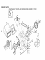
REPAIR PARTS CRAFTSMAN
i ,i,
ii
iii
ii
22" ROTARY LAWN MOWER
MODEL NUMBER
917.373231
--'='_
--1
Ji
i
i
i,
5
I
\\\
54
h,,1
18
10
14
28
I
41
15
9
8
7
13
12
REPAIR PARTS
CRAFTSMAN
KEY
NO.
ro
¢o
1
2
3
4
5
6
7
8
9
10
!1
12
13
!4
15
16
18
PART
NO.
137076
48029
74189
750029
137078
700875
85179
77400
52160
86960
700953
12000057
137054
88080
88118
67725
87877
22" ROTARY
LAWN MOWER
MODEL NUMBER
DESCRIPTION
KEY PART
NO.
NO
Control Cable Assembly
Control Head Kit
Locknut #10-24
Pan Head Machine Screw
V-Belt
Carriage Bolt 1/4-20 x 2
Retainer Clip
Hubcap
Washer
Nylon Bushing
Wheel & Tire Assembly
E-Ring
Pinion
Dust Cover
Felt Washer
Washer 1/2 x 1-1/2 x.134
Selector Knob
25
26
27
28
31
32
33
34
35
36
37
38
40
41
53
54
55
56
#10-24 x 2
702182
87866
750097
137088
132010
137052
48323
850848
700339
702511
137090
STD541425
75192
700340
88614
751663
86012
851552
917.373231
DESCRIPTION
Drive Cover Decal
Pan Head Tapping Screw #10-24 x 2-3/4
Hex Washer Head Screw #10-24 x 3/4
Dnve Cover
Hex Flange Nut
Drive Pulley
Drive Control Cable Kit
Hi-Pro Key
Wheel Adjuster Assembly (Left)
Gear Case Assembly
Spring
Locknut 1/4-20
. Spring
Wheel Adjuster Assembly (Right)
Frame Assembly
Grassbag Assembly
Driveshaft Cover
Screw, Pan Head, Hi-Lo #10-16 x 1/2
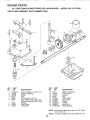
REPAnR PARTS
22" CRAFTSMAN
POWER
GEAR CASE ASSEMBLY
PROPELLED
PART NUMBER
LAWN
MOWER
- - MODEL
NO. 917.373231
702511
17
15
14
18
9
19
KEY
NO.
PART
NO.
1
2
3
4
5
6
17490416
137055
137053
57072
57388
48281
7
8
9
77881
137051
137074
DESCRIPTION
Screw, Tapping 1/4-20 x 1-1/4
Bracket, Adjusting
Shifter
Seal
Pin, Grooved 1/8 x 1/2
Gear Case Halves, Upper and
Lower (Includes Key #4, 5 and 7)
Bearing
Shaft, Worm
Drive Shaft
KEY
NO.
PART
NO.
10
11
12
13
14
15
16
17
18
19
57079
131484
700343
86447
137050
750436X
750355
t2000003
850848
81585X004
DESCRIPTION
Washer, Hardened
Yoke, CEutch
Bushing
Plug
Gear, Helical
Jaw, Clutch
Grease
E-Ring
Key, Hi-Pro
Spring Bracket
NOTE: All component dimensions given in U.S. inches
1 inch = 25,.4 mm
NOTE: To reseal housing halves use Locktite No_ 515
24
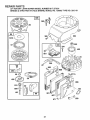
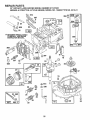
REPAIR PARTS
22" ROTARY LAWN MOWER MODEL NUMBER 917.373231
BRIGGS & STRATTON
4-CYCLE ENGINE, MODEL NO. 126802 TYPE NO. 3215-01
572
9
_
52
_
REQUIRES SPECIAL TOOLS
TO INSTALL. SEE REPAIR
INSTRUCTION MANUAL.
383
....
40
_4_ _
34
4O
35
592
_20
33
25
22
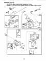
REPAIR PARTS
22" ROTARY LAWN MOWER MODEL NUMBER 917.373231
BRIGGS & STRATTON 4-CYCLE ENGINE, MODEL NO. 126802 TYPE NO. 3215-01
618
188A
258
620
iiiii iiiiii
iii
670A
;
I
I
124
G 634
t
130
127
t
0 i
t
617
_j
116_
26
REPAnR PARTS
22" ROTARY LAWN MOWER MODEL NUMBER 917.373231
BRIGGS & STRATTON
4-CYCLE ENGINE, MODEL NO. '126802 TYPE NO. 32'15-01
.........................
16o8
363
55
305
304
_332
57
334
455
851
23
s9
_971A
?
456
966
515
69AO
461
991
967
971 _
27
_529
REPAgR PARTS
22" ROTARY LAWN MOWER MODEL NUMBER 917.373231
BRIGGS & STRATTON
4-CYCLE ENGINE, MODEL NO. 126802 TYPE NO. 3215-01
949
_P
346
1019
387
670
81
@
353
@
601
12
358 GASKET SET
Q
_116
634
977 CARBURETOR
7_ _
104
61
GASKET
SET
121 CARBURETOR
28
127
1
OVERHAUL
KIT!
116
634 G
617 ..................
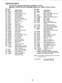
REPA6R PARTS
22" ROTARY LAWN MOWER MODEL NUMBER 917.373231
BRIGGS & STRATTON
4-CYCLE ENGINE, MODEL NO. 126802 TYPE NO. 3215-01
KEY
NO.
1
2
3
5
7
8
9
9A
10
11
12
13
I5
16
18
20
22
23
24
25
26
27
28
29
32
33
34
35
38
40
45
PART
NO.
494062
399269
299819
213861
2722OO
494489
272481
272238
94650
231685
272198
94547
94720
493362
94388
493279
399781
94220
94612
492177
222698
494058
494059
494060
494061
493261
493388
493389
493390
26026
298909
298908
490566
490743
94405
262651
262652
262224
94608
93312
262204
KEY
NO.
46
47
52
54
55
56
57
58
DESCRIPTION
Cylinder Assembly
Bushing, Cylinder
* Seal, Oil
Head, Cylinder
"Gasket, Cylinder Head
Breather, Valve Chamber
* Gasket, Valve Cover
* Gasket, Baffle Plate
Screw, Breather Mounting
Tube, Breather
* Gasket, Crankcase
Screw, Cylinder Head
PIug, Oil Drain
Crankshaft
Timing Gear Key
Sump, Engine
* Seal, Oil
Screw, Sump Mounting, Seres
Screw, Sump Mounting
(Used in Hole Nearest Breather)
Flywheel, Magneto
Key, Flywheel
Piston Assembly, Standard Size
Piston Assembly .010" Oversize
Piston Assembly .020" Oversize
Piston Assembly .030" Oversize
Ring Set, Piston, Standard Size
Ring Set, Piston o010" Oversize
Ring Set, Piston ,.020" Oversize
Ring Set, Piston .030" Oversize
Lock, Piston Pin
Pin Assembly, Piston, Standard
Pin Assembly, Piston ,.005" Over
Rod Assembly, Connecting
Rod Assembly, Connecting
.020" Undersize Crankpin Bearing
Screw, Connecting Rod
Valve, Exhaust
Valve, Intake
Spring, Valve
Screw, Hex Head
Retainer, Valve Spring
Tappet, Valve
59
60
65
69
69A
81
95
98
98A
104
116
118
121
124
125
127
130
131
133
134
137
163
187
!88
188A
201
209
227
230
258
284
PART
NO.
492830
493737
272199
94526
492831
493824
262594
280399
DESCRIPTION
Gear, Cam
Oil Slinger Gear and Bracket
* Gasket, intake Elbow
Screw, Intake Elbow Mounting
Housing, Rewind Starter
Pulley, Rewind Starter
Spring, Rewind Starter
Rope, Rewind Starter
(Cut To 88-5/8")
396892
Insert, Handle
393152
Handle, Rewind Starter
94696
Screw, Guard Mounting
280973
Washer, Rewind Starter
224322
Washer, Rewind Starter
223664
Lock, Muffler Screw
94098
Screw, Seres,
Throttle Valve Mounting
398185
Screw, Idle Adjustment
493280
Screw Assembly, Speed Adjust
231371
_* Pin, Float Hinge
--*** Gasket, Sealing (Sold in Kit Only)
493765
** Valve and Spring, Needle
493762
Carburetor Overhaul Kit
94525
Screw, Carburetor Mounting
493627
Carburetor Assembly
--** Plug, Welch (Sold in Kit Only)
223470
Valve, Throttle
493267
Shaft and Lever, Throttle
398187
Float Assembly, Carburetor
398188
** Valve, Inlet (Includes Seat)
--*** Gasket, Bowl (Sold in Kit Only)
272296
* Gasket, Air Cleaner
492790
Hose, Fuel
398540
Screw, Tank Mounting
(Includes Washer)
94644
Screw, Hex Head
262579
Link, Governor
262660
Spring, Governor
492349
Lever Assembly, Governor
67072
Washer, Governor Crank
94512
Screw, Hex Head
94511
Screw, Hex Head
Included in Gasket Set (493263)
Included in Carburetor Overhaul Kit (493762)
Included in both Carburetor Overhaul Kit (493762),
and Carburetor Gasket Set (490937)
NOTE:
29
Atl component dimensions given in U..S, inches
1 inch = 25°4 mm
REPAIR PARTS
22" ROTARY LAWN MOWER MODEL NUMBER 917.373231
BRIGGS & STRATTON 4-CYCLE ENGINE, MODEL NO. 126802 TYPE NO. 3215-01
KEY PART
NOo NO.
300 490547
304 493293
305 94744
306 224324
307 94515
332 92284
333 802574
334 94731
337 802592
346 94602
353 94581
356 398808
358 493263
363 19069
383 89838
387 394281
455 224250
456 224321
459 492833
461 262626
515 262625
523 493950
524 280393
525 493952
528 399254
529 280943
562 92613
572 224328
592 231082
601 93807
6"01A 94171
608 493295
Includes:
6!3 94231
615 94474
6t6 262578
617 270344
620 493895
KEY
NO.
621
625
634
635
670
670A
741
832
842
843
847
DESCRIPTION
Muffler, Exhaust
Housing, Blower
Screw, Seres, Hex Head
Shield, Cylinder
Screw, Hex Head
Nut, Flywheel
Armature, Magneto
Screw, Armature Mounting
Plug, Spark
Screw, Hex Head
Locknut
Wire, Ground
Gasket Set
Puller', Flywheel
Wrench, Spark Plug
Primer, Fuel
Cup, Starter
Retainer-, Rewind Starter
Pawl, Starter
Pin, Starter
Spring, Torsion
Cap With Dipstick, Oi! Filler'
* Seal, Filler Tube
Tube, Oil Filler
Hose, Primer
Grommet, Breather
Bolt, Governor Lever
Baffle, Cylinder
Nut, Hex
Clamp, Hose, Black
Clamp, Hose
Starter Assembly, Rewind
94128 Screw, Hex Head
92987 Nut, Hex
Screw, Muffler' Mounting
Pushnut, Governor Crank
Crank, Governor
*** Seal, Fuel Intake Tube
Bracket Assembly,
Carburetor Control
851
869
870
871
922
923
949
955
957
966
967
968
969
971
971A
972
975
977
991
1016
1019
PART
NO.
396847
492717
--66538
280512
493823
262598
494224
280966
272616
493459
DESCRIPTION
Switch, Stop
Tube, Fuel intake
*** Washer, Shaft (Sold in Kit Only)
Elbow, Spark Plug
Spacer, Fuel Tank
Spacer, Carburetor Bracket (2)
Gear, Timing
Guard, Muffler
* Seal, O-Ring
Sleeve, Control Lever'
Dipstick and Tube Assembly,
Oil Filler
221798
Terminal, IgnitiOn Cable
213512
Seat, Intake Valve, Standard
213513
Seat, Exhaust Valve, Standard
262001
Guide, Exhaust Valve
63709
Guide, Intake Valve
(See Repair instruction Manual)
262640
Spring, Brake
493442
Brake Assembly
281191
Guard, Finger
493637
Screw, Fuel Bowl, Standard
397974
Cap Assembly, Fuel
494735
Base, Air Cleaner
491588
Filter, Air
281069
Cover, Air Cleaner
94173
Screw, Cover Mounting
94269
Screw, Air Cleaner
94121
Screw, Base to Carburetor
495224
Tank Assembly, Fuel
493640
Bowl Assembly, Carburetor
490937
Gasket Set, Carburetor
493537
Pre-Filter
224278
Cover, Rewind Starter
495354
Label Kit
Included in Gasket Set (493263)
Included in Carburetor Overhaul Kit (493762)
Included in both Carburetor Overhaul Kit(493762),
and Carburetor Gasket Set (490937)
NOTE:
All component dimensions given in U.S. inches
1 inch = 25_4 rnm
RPM Settings:
3O
Low Speed 1900-2100
High Speed 3000-3200
SERVICE
31
NOTES
®
MANUAL
5.0 HORSEPOWER
22" REAR DISCHARGE
3 in ONE Convertible
POWER PROPELLED
ROTARY LAWN MOWER
Each lawn mower has its own model number.
gine has its own model number,.
MODEL NO.
917.373231
Each en-
The model number for your lawn mower will be found on a
decal attached to the rear of the lawn mower housing_
The model number for your engine will be found on the
blower' housing of the engine.
All parts listed herein may be ordered from any Sears,
Roebuck and Co. Service Center/Department and most
Retail Stores._
WHEN ORDERING REPAIR PARTS, ALWAYS GIVE THE
FOLLOWING INFORMATION:
= PRODUCT-
LAWN MOWER
° MODEL NUMBER - 917.373231
HOW TO ORDER
REPAUR PARTS
° ENGINE MODEL NO. - 126802, TYPE NO. 3215-01
o PART NUMBER
° PART DESCRIPTION
Your Sears merchandise has added value when you
consider Sears has service units nationwide staffed with
Sears trained technicians,_
professional technicians
specifically trained to insure that we meet our pledge to
you, we service what we sell.
702553
,,, ,,,,,,,'mlllllll
02/02/93
llllllllll'llll'll=ll
Printed in U.S_A.,
.............................IIII'11111'11
II
IIIIIIIII1'111111
®
MODEL
917.373231
OWNER'SMANUAL
TM
Conv_rt_bm_
° AssembHy
° Operation
o Customer
Responsibilities
° Service
° Adjustments
o Repair Parts
Caution:
Read and Follow
all Safety Rules
and Instructions
Before Operating
This Equipment
SAFETY RULES
REPAIRS.
IMPORTANT
SAFETY STANDARDS REQUIRE OPERATOR PRESENCE CONTROLS
SUCH CONTROLS_
DO NOT ATT'EMPT TO DEFEAT THE FUNCTION
STANCES°
TO MINIMIZE THE RISK OF INJURY. YOUR UNIT IS EQUIPPED WITH
OF THE OPERATOR PRESENCE CONTROLS UNDER ANY CIRCUM-
TRAINING:
•
Read this operator's manual carefully.. Become familiar with
the controls and know how to operate your mower properly.
Learn how to quickly stop mower.
°
Always stop the engine whenever you leave or are not using
your mower, or before crossing driveways, walks, roads, and
any gravel-covered areas.
•
Do not allow children to use your mower. Never allow adults
to use mower without proper instructions
•
Never direct discharge of material toward bystanders nor
allow anyone near tire mower while you are operating it.
•
Keep the area of operation clear of all persons, especially
small children and pets.
•
°
Use mower only as the manufacturer
scnbed in this manual.
Before cleaning, inspecting, or repairing your mower, stop
the engine and make absolutely sure the blade and all
moving parts have stopped. Then disconnect the spark plug
wire and keep it away from the spark plug to prevent
accidental starting.
•
Do not operate mower if it has been dropped or damaged in
any manner., Always have damage repaired before using
your mower:_
•
Do not continue to run your mower if you hit a foreign objecL
Follow the procedure outlined above, then repair any damage before restarting and operating you mower..
•
Do not use accessory attachments that are not recommended by the manufacturer._ Use of such attachments may
be hazardous.
•
Do not change the governor settings or overspeed the
engine_ Engine damage or personal injury may result.
•
Do not operate your mower if it vibrates abnormally. Excessive vibration is an indication of damage; stop the engine,
safely check for the cause of vibration and repair as required.
•
Do not run the engine indoors.. Exhaust fumes are danger-
Be aware that
running
intended and as de-
the mower blade turns when the engine is
PREPARATION:
OUS,,
•
Always wear safety glasses or' eye shields when starting and
while using your mower_
Never cut grass by pulling the mower towards you. Mow
across the face of slopes, never up and down or you might
lose your footing, Do not mow excessively steep slopes..
Use caution when operating the mower on uneven terrain or
when changing directions - maintain good footing.
•
Dress properly. Do not operate mower when barefoot or
wearing open sandals. Wear only solid shoes with good
traction when mowing.
Never operate your mower without proper guards, plates,
grass catcher or other safety devices in place_
MAINTENANCE
"
Always thoroughly check the area to be mowed and clear it
of all stones, sticks, wires, bones, and other foreign objects..
These objects will be thrown by the blade and can cause
severe injury..
°
°
•
Check fuel tank before starting engine. Do not fill gas tank
indoors, when the engine is running or when the engine is hot.
Allow the engine to cool for several minutes before filling the
gas tank.. Clean off any spilled gasoline before starting the
engine.
AND STORAGE:
•
Check the blade and the engine mounting bolts often to be
sure they are tightened properly.
•
Check all bolts, nuts and screws at frequent intervals for
proper tightness to be sure mower is in safe working condition.
•
Always make wheel height adjustments before starting your
mower. Never attempt to do this while the engine is rvnning.
•
Keep all safety devices in place and working
•
Mow only in daylight or good artificial light
•
To reduce fire hazard, keep the engine free of grass, leaves
or excessive grease and oil
•
Check grass catcher often for deterioration and wear and
replace worn bags. Use only replacement bags that are
recommended by and comply with specifications of the
manufacturer of your rnower_.
•
Always keep a sharp blade on your mower.
•
Allow engine to cool before storing in any enclosure.
•
Never store mower with fuel in the tank inside a building
where fumes may reach an open flame or an ignition source
such as a hot water heater, space heater, clothes dryer, etc.
OPERATION:
•
Keep your eyes and mind on your mower and the area being
cuL Do not let other interests distract you.
o
Do not mow wet or slippery grass.. Never run while operating
your mower. Always be sure of your footing- keep a firm hold
on the handles and walk.
Do not put hands or feet near or under rotating parts. Keep
clear of the discharge opening at all times.
....................................................
LOOK FOR THIS SYMBOL
IT MEANSATTENTION!!!
, ,,,, ,,,,,,,,,
TO POINT OUT IMPORTANT
BECOME ALERT!!!
YOUR
2
SAFETY
PRECAUTIONS.
SAFETY IS INVOLVED,
CONGRATULATIONS
on your purchase of a Sears
Craftsman Lawn Mower_ It has been designed, engineered
and manufactured to give you the best possible dependability and performance_
Should you experience any problems you cannot easily
remedy, please contact your nearest Sears Service CentedDepartment.
Sears has competent, welt trained technicians and the proper tools to service or repair this unit.
Please read and retain this manual.. The instructions wilt
enable you to assemble and maintain your lawn mower
properly. Always observe the "SAFETY RULES'L
MODEL
NUMBER
PRODUCT
917,373231
SPECIFICATIONS
HORSEPOWER:
5.0
DISPLACEMENT:
11 ..57 cue in,,
GASOLINE CAPACITY:
1o6 quarts
(Unleaded)
OIL (20 ozo Capacity):
SAE 30 (Above 32°F)
5W30 (Below 32°F)
SPARK PLUG (Gap ..030 ino):
(0_76 mm)
Champion
RJ19LM or
Sears zt 33312
or STD 361458
or STD 360950
VALVE CLEARANCE:
°005-°007 ino
o007-_009 in.
SERIAL
NUMBER
DATE OF
PURCHASE
THE MODEL AND SERIAL NUMBERS WILL BE
FOUND ON A DECAL ATTACHED TO THE REAR
OF THE LAWN MOWER HOUSING,.
YOU SHOULD RECORD BOTH SERIAL NUMBER
AND DATE OF PURCHASE AND KEEP IN A SAFE
PLACE FOR FUTURE REFERENCE,.
MAINTENANCE
SOLID STATE IGNITION
AIR GAP:
o010 in,.
BLADE BOLT TORQUE:
35-40 ft.-Ibs_
AGREEMENT
A Sears Maintenance
CUSTOMER
intake:
Exhaust:
Agreement is available on this producL
Contact your nearest Sears store for details.
RESPONSIBILITIES
= Read and observe the safety rules..
• Follow a regular schedule in maintaining, caring for and using your lawn mower.
= Fo]fow the instructions under "Customer Responsibilities"
LIMEED
TWO YEAR WARRANTY
and "Storage" sections of this Owner's Manual
ON CRAFTSMAN
POWER MOWER
For two years from date of purchase, when this Craftsman Lawn Mower is maintained, lubricated, and tuned up
according to the operating and maintenance instructions in the owner's manual, Sears will repair free of charge any
defect in material or workmanship.
If this Craftsman Lawn Mower is used for commercial or rental purposes, this warranty applies for only 90 days
from the date of purchase,_
This Warranty does not cover:
•
Expendable items which become worn during normal use, such as rotary mower blades, blade adapters, belts,
air cleaners and spark plug.
°
Repairs necessary because of operator abuse or negligence, including bent crankshafts
maintain the equipment according to the instructions contained in the owner's manual.
and the failure to
WARRANTY SERVICE IS AVAILABLE BY RETURNING THE CRAFTSMAN POWER MOWER TO THE NEAREST SEARS SERVICE CENTERIDEPARTMENT
IN THE UNITED STATES. THIS WARRANTY APPLIES ONLY
WHILE THIS PRODUCT IS IN USE IN THE UNITED STATES_
This Warranty gives you specific legal rights, and you may also have other rights which vary from state to state.
SEARS, ROEBUCK AND CO.., D/817 WA, HOFFMAN ESTATES, ILLINOIS 60179
TABLE OF CONTENTS
SAFETY RULES .............................................
2
PRODUCT SPECIFICATIONS
........................ 3
CUSTOMER
RESPONSIBILITIES
...... 3, 12-14
WARRANTY ....................................................
3
LAWN MOWER ACCESSORIES
................... 5
ASSEMBLY .....................................................
6
OPERATION
...................................................
8
SERVICE AND ADJUSTMENTS
.................. 15
STORAGE .....................................................
18
TROU B LESHOOTING ..................................
19
REPAIR PARTS - LAWN MOWER ......... 20-24
REPAIR PARTS - ENGINE ...................... 25-30
PARTS ORDERING/SERVICE.
BACK COVER
mNDEX
A
Accessories ............................................. 5
Adjustments:
Carburetor .................................. 17
Handle Height ............................ 16
Height of Cut ................................ 9
Air Filter:
Service ........................................
14
Assembly:
Handle ..........................................
6
Grass Catcher .............................. 7
B
Blade:
Sharpening ................................. 13
Replacement .............................. 13
C
Controls:
Operator Presence Control Bar .8
Drive Control ................................ 8
Customer Responsibilities
..... 3, 12-14
Air Filter ......................................
14
Blade Care/Replacement
.......... 13
Drive Wheels .............................. 13
Engine ........................................
14
Gear Case ...................................
13
Lubrication ................................. 12
Spark Plug ..................................
E
Engine:
Oil Change .................................
Oil Level .....................................
Oil Type ......................................
Starting .......................................
Storage .......................................
14
14
14
14
10
18
P
F
Fuel:
Type .............................................
Storage .......................................
10
18
H
Repair Parts
Lawn Mower ..........................
Engine. ..................................
R
Responsibilities,
20-24
25-30
Customer .... 3, 12-14
S
Handle:
Adjustment .................................. 16
Assembly ........................................ 6
L
Lubrication:
Safety Rules ........................................
See,ice and Adjustments:
Carburetor'. .................................
Drive Belt ...................................
17
15
Engine ........................................
12
Rear Door Hinge ......................... 12
Handle Bracket Mounting Pin .. 12
Wheel Adjuster .......................... 12
M
Engine Speed ............................
Handle ........................................
17
16
Maintenance Agreement .................... 3
Maintenance Schedule ..................... 12
Mowing Tips ...................................... 11
Mulching/Mowing Tips ..................... 11
O
Oil:
Engine ........................................
14
Storage .......................................
18
Operation:
Operating Lawn Mower'. .............. 9
Drive Control ................................ 9
Operator Presence Control Bar ..... ;..8
Options:
Attachments ................................. 5
4
Spark Plug .........................................
Specifications .....................................
Starting the Engine ..........................
Stopping the Engine ........................
Storage ..............................................
2
14
3
10
10
18
T
Trouble Sirooting Chart ................... 19
W
Warranty ..............................................
Wheels:
Wheel Adjusters ..........................
3
8
These accessories were available when this lawn mowerwas produced _They are also available at most Sears retail outlets,
catalog and service centers_ Most Sears stores can also order repair parts for you, when you provide the model number of
your lawn mower° Some of these accessories may not apply to your lawn mower.
ENGmNE
SPARK PLUG
AIR FILTER
MUFFLER
GAS CAN
CHARGER
ENGINE OIL
STABILIZER
BATTERY
if lawn mower is an electric start
LAWN MOWER
PERFORMANCE
DUST SHIELD
CUPPING DEFLECTOR
REAR BAG
OPTIONAL
FABRIC BAG
REPLACEMENT
BAG FOR REAR
DISCHARGE
LAWN MOWERS
SIDE DISCHARGE
CATCHER
OPTIONAL
CATCHER FOR
SIDE DISCHARGE
LAWN MOWER
t
LAWN P/lOWER MAINTENANCE
,=,ljl ill
.......
BELT
BLADE
BLADE
ADAPTER
%
5
LAWN MOWER
COVER
Read these instructions and the Operator's Manual in its
entirety before you attempt to assemble or operate your
new lawn mower.. Your new lawn mower has been assernbled at the factory with the exception of those parts left
unassernbled for shipping purpose& To ensure safe and
proper operation of your lawn mower, all parts and hardware you assemble must be tightened securelyv Use the
correct tools as necessary to ensure proper tightness. All
parts such as nuts, washers, bolts, etc., necessary to
complete the assembly have been placed in the parts bag
TO REMOVE
CARTON
°
•
•
OPERATOR PRESENCE
CONTROLBAR
UPPER HANDLE
LIFT UP
LAWN MOWER FROM
MOWING POSITION
Remove loose parts included with mower.
Cut down two end corners of carton and lay end panel
down flat..
Remove all packing materials except padding between
upper and lower handle and padding holding operator
presence control bar to upper handle_
Roll lawn mower out of carton and check carton thoroughly for additional loose parts.
LOWER HANDLE
FIG. 1
SLOTS
HOW TO SET UP YOUR LAWN
MOWER
TO UNFOLD
HANDLE
(See Fig. 1)
IMPORTANT:
UNFOLD HANDLE CAREFULLY SO AS
NOT TO PINCH OR DAMAGE CONTROL CABLES
o Raise handles until lower handle section locks into
place in mowing position.
o Raise upper handle section into place on lower handle,
remove protective padding and tighten both handle
knobs..
°
Remove handle padding holding operator presence
control bar to upper- handle.,
•
Your lawn mower handle can be adjusted for your
mowing comfort,
Refer to "Adjust Handle" in the
Service and Adjustment section of this manual,
TO INSTALL
ATTACHMENTS
MULCHER
FIG, 2
(See Fig. 2)
Your lawn mower" was shipped ready to be used as a
mulchero To convert to bagging or discharging:
•
•
°
PLATE
Open rear door and remove mulcher plate, Store
rfiulcher plate in a safe place..
You can now install Latchetor optional clipping deflector',
To return to mulching operation, install mulcher plate
into discharge opening of mower_ Be sure all tabs are
seated properly,
CAUTION: Do not run your lawn mower
without mulcher plate in place or approved clipping deflector or grass
catcher in place, Never attempt to operate the lawn mower with the rear door
removed or propped open.
6
TABS
ASSE
TO ASSEMBLE
& ATTACH
CATCHER
(See Figs. 3-4)
o
°
BLY
CATCHER FRAME
GRASS
Put grass catcher frame into grass bag with rigid part
of bag on the bottom.
Slip vinyl bindings over frame.
\
NO'[E: If vinyl bindings are too stiff, hold them in warm
water for a few minutes If bag gets wet, let it dry before
using.
o
-
Lift the rear door on the mower housing and place the
grass catcher frame onto the formed tabs on the rear
door hinge bracket_
The grass catcher is secured to the lawn mower
housing when the rear door is lowered onto the grass
catcher frame.
FIG. 3
/
HINGE
BRACKET
_._
REAR DOOR
FORMED
TABS
GRASS CATCHER
FIG. 4
7
FRAME
OPERATION
KNOW YOUR LAWN MOWER
READ THIS OWNER'S MANUAL AND SAFETY RULES BEFORE OPERATING YOUR LAWN MOWER. Compare the
illustrations with your lawn mower' to familiarize yourself with the location of various controls and adjustments. Save this
manual for future reference_
ENGINE ZONE CONTROL
CABLE
OPERATOR
PRESENCECONTROLBAR
DRIVE CONTROL
STARTER
LEVER
HANDLE
CABLE CLIPS
ENGINE OIL CAP W/DIPSTICK
GRASSCATCHER
GASOLINE
MULCHER
CAP
DRIVE COVER
PLATE
PRIMER
ENGINE
SPEED CONTROL
AIR FILTER
HOUSING
WHEEL ADJUSTER
(ON EACH WHEEL)
FIG. 5
,_llllll
.................................
MEETS
CPSC SAFETY
REQUIREMENTS
Sears rotary walk-behind power lawn mowers conform to the safety standards of the American National Standards Institute
and the U_S_Consumer Product Safety Commission. The blade turns when the engine is running.
_J
iLi
i ii i i i
lllll
,i,
i::ll:u,
OPERATOR PRESENCE CONTROL
- must be held
down to the handle to start the engine., Release to stop the
engine.
ENGINE SPEED CONTROL
- located on the side of the
PRIMER - pumps additional fuel from the carburetor to the
cylinder for use when starting a cold engine_
MULCHER PLATE - located at the discharge opening,
must be removed when converting to bagging or discharge
operation,
engine which allows you to select either fast (,r_) or' slow
(,_) engine speed.
STARTER HANDLE - used for starting the engine°
DRIVE CONTROL LEVER - used to engage power-propelled forward motion of lawn mower..
8
OPERATION
:, ,llll,l,llll:
lllll,l,,ll,i, ill,,
HOW TO USE YOUR LAWN MOWER
ENGINE SPEED
CAUTION: Do not run your lawn mower
without mtdcher plate in place and door
closed orwithout an approved clipping
deflector or grasscatcher
in place.
Never attempt to operate the lawn
mower with the rear door removed or
propped openf
ENGINE
SPEED
(See Fig. 6)
The engine speed is controlled by a lever located on the
side of the engine. Fast (,_) position is for starting the
engine, normal cutting, and better grass bagging. Slow
(-_) position is for light cutting, trimming and fuel economy.
ENGINE
FIG. 6
LOWER WHEELS
FOR HIGH CUT
RAISE WHEELS
FOR LOW CUT
ZONE CONTROL
CAUTION: Federal regulations require
an engine control to be installed on this
lawn mower in order to minimize the
risk of blade contact injury, Do not under any circumstances attempt to defeat the function of the operator control.
The blade turns when the engine is
running,
o
Your lawn mower is equipped with an operator presence control bar which requires the operator to be
positioned behind the lawn mower handle to start and
operate the lawn mower..
TO ADJUST
=
o
•
•
°
°
o
(See Fig. 7)
GRASS
CATCHER
(See Fig. 8)
To remove grass catcher, release operator presence
control bar to stop engine.
Lift up rear door and remove the grass catcher by the
handle°
Do not drag the bag when emptying;
it will cause
unnecessary wear.
DRIVE CONTROL
=
HEIGHT
Raise wheels for low cut and lower wheels for high cut
Wheels are set in low cut for shipping.. Adjust cutting
height to suit your requirements. Medium position is
best for most lawns..
To change cutting height, squeeze adjuster lever toward wheel
Move wheel up or down to suit your
requirements.. Be sure afl wheels are in the same
setting,
TO EMPTY
•
CUTTING
FIG. 7
FIG. 8
\
(See Fig. 9)
Self-propelling is controlled by holding the operator
presence control bar down to the handle and pushing
the drive control lever forward until it clicks; then
release the lever..
Forward motion will stop when the operator presence
control bar is retease& To stop forward motion without
stopping engine, release the operator presence control
bar slightly until the drive control disengages,
Hold
operator presence control bar down to handte to continue mowing without self-propelling..
To keep drive control engaged when turning corners,
push down on handle and lift front wheels off ground
while turning lawn mower.
OPERATOR PRESENCE
CONTROL BAR
DRIVE
CONTROL
DRIVE CONTROL
FIG. 9
9
OPERAON
BEFORE STARTONG ENGItNE
ENGINE OIL CAP
W/DIPSTICK
OIL (See Fig. 10)
Your lawn mower is shipped without oil in the engine°
.
Be sure mower is level and area around oif fill is clean_
o
Remove engine oi! cap w/dipstick and fill to the full line
on the dipstick_
•
Use 20 ozs. of oi!. For type and grade of oi! to use, see
"ENGINE" in Customer Responsibilities section of this
manual,
o
Pour oil siowly_ Do not over fill,,
°
Check oil level before each user Add oil if needed,, Fill
to full line on dipstick,
° To read proper level, tighten engine oil cap each timev
°
Reinstall engine oil cap and tighten..
•
After the first two (2) hours of mowing, change the oil,
and every 25 hours thereafter_ You may need to
change the oil more often under dusty, dirty conditions.
GASOLINE
FIG. 10
TO START ENGINE
GAS (See Fig. 10)
°
FILLER CAP
°
Fill gasoline tank with fresh, clean, unleaded gasoline.
DO NOT USE PREMIUM GASOLINE. BE CAREFUL
NOT TO OVER FILL TANK..
WARNING:
Experience indicates that alcohol blended
fuels (called gasohol or using ethanol or methanol) can
attract moisture which leads to separation and formation of
acids during storage° Acidic gas can damage the fuel
system of an engine while in storage. To avoid engine
problems, the fuel system should be emptied before storage of 30 days or longer.. Drain the fuel tank, start the
engine and let it run until fuel lines and carburetor are
empty. Use fresh fuel next season. See Storage Instructions for' additional inforrnation_ Never use engine or
carburetor cleaner products in fuel tank or permanent
damage may occur,,
.
=
°
To start a cold engine, push pnmer three (3) times
before trying to start. Use a firm push, This step is not
usualty necessary when starting an engine which has
already run for a few minutes.
Move engine speed control lever to fast (,_) position_
Hold operator presence control bar down to the handle
and pull starter handle quickly_, Do not allow starter' rope
to snap back.
To stop engine, release operator' presence control
bar.
NOTE: In cooler weather it may be necessary to repeat
priming steps. In warmerweather over priming may cause
flooding and engine will not start. If you do flood engine,
wait a few minutes before attempting to start and do not
repeat priming steps,,
10
OPERATIO
MOWING
o
TraPS
Under certain conditions, such as very tall grass, it
may be necessary to raise the height of cut to reduce
pushing effort and to keep from overloading the engine and leaving dumps of grass clipping&
°
For extremely heavy cutting, reduce the width of cut
and raise the rear of the lawn mower housing one (1)
wheel adjuster setting higher than the front for better
discharge of grass.
o
For better grass bagging and most cutting conditions,
the engine speed should be set in the fast (,_) position°
o
When using a rear discharge lawn mower in moist,
heavy grass, clumps of cut grass may not enter the
grass catcher. Reduce ground speed (pushing speed)
and/or run the lawn mower over the area a second
time°
•
•
°
MAX 1/3
FIG. 11
If a trail of grass clippings is ieft on the right side of a
rear discharge lawn mower, mow in a clockwise
direction with a small overlap to collect the clippings
on the next pass°
Keep top of engine around starter clear and clean of
grass clippings and chaff. This will help engine air
flow and extend engine life.
°
•
Pores in cloth grass catchers can become filled with
dirt and dust with use and catchers will collect less
grass. To prevent this, regularly hose catchers off
with water and let dry before using°
MULCHING
MOWING
TIPS
IMPORTANT,'
FOR BEST PERFORMANCE,
KEEP
MOWER HOUSING FREE OF BUILT-UP GRASS AND
TRASH. CLEAN AFTER EACH USE.. SEE "CLEANING"
IN CUSTOMER RESPONSIBILITIES SECTION OF THIS
MANUAL.
°
The special mulching blade will recut the grass clippings many times and reduce them in size so that as
they fall onto the lawn they will disperse into the grass
and not be noticed.. Also, the mulched grass will
biodegrade quickly to provide nutrients for the lawn..
Always mulch with your highest engine (blade) speed
as this will provide the best recutting action of the
blades.
°
,
11
Avoid cutting your lawn when it is wet. Wet grass
tends to form clumps and interferes with the mulching
action.. The best time to mow your lawn is the early
afternoon. At this time the grass has dried and the
newly cut area will not be exposed to the direct sun°
For best results, adjust the lawn mower cutting height
so that the lawn mower cuts off only the top one-third
of the grass blades (See Fig° 11). If the lawn is
overgrown it will be necessary to raise the height of cut
to reduce pushing effort and to keep from overloading
the engine and leaving clumps of mulched grass. For
extremely heavy mulching, reduce your width of cut,
mow slowly and raise the rear of the lawn mower one
wheel adjuster setting higher than the front.
Certain types of grass and grass conditions may
require that an area be mulched a second time to
completely hide the clippings.. When doing a second
cut, mow across or perpendicular to the first cut path..
Change your cutting pattern from week to week. Mow
north to south one week then change to east to west
the next week. This will help prevent matting and
graining of the lawn_
CUSTOMER
ESIPONSH ILHTI
MAI.TENA.CE
SC,EDULE
FILL IN DATES
_:k_ _,_1 _ _,
YOU
Clean/inspect
(If Equipped)
X
°
cubi-icat_on
Cha_
E
N
Check Eng,i,ne Oil Level
Change Engine Oil
G
clean Air Filter
Inspect Muffler
Replace Spark P!ug
__
.
Change
Service
Replace
Charge
......
.
6/'........
I
I
..................
U
U
....
6/
6/ ..........
6/4
6/
,,..
:
_
........
''":':'.".'.'."."."."i
....
......
_2 .....
Replace Air Filter Paper Cartridge
-
_'-o
.......................
A
Clean Batte ry/R ecii,_rge
(Electric Start Mowers)
t
2
3
4
_,,
Grass Ca'{'cher
_..........
, ...................H64_ 6/
Inspect/Clean
Diive Wheels
Clean Lawn Mower'
'.............
(Self-Propelled Mowers)
R sharpeniRepiace
MoWerBiade
N
,-4,
more often when operating under a heavy load or in high ambient lemperatures,
more often when operating in dirty or' dusty conditions,,
blades more often when mowing in sandy soil
48 hours at end of season.
GENERAL
LUBRaCATUON CHART
RECOMMENDATIONS
"]:.hewarranty on this lawn mower does not cover items that
have been subjected to operator abuse or' negligence. To
receive full value from the warranty, operator must maintain
mower as instructed in this manual.
Some adjustments will need to be made periodically to
properly maintair! your unit..
All adjustments in the Service and Adjustments section of
this manual should be checked at least once each season°
o
o
Once a year, replace the spark plug, replace air filter
element and check blade for wear_ A new spark plug
and clean/new air filter element assures proper air-fuel
mixture and helps your engine run better and last
longer..
Follow the maintenance schedule in this manual.
BEFORE
=
o
EACH
USE
(_) HANDLE BRACKET
MOUNTING PIN
Check engine oil level..
Check for loose fasteners..
(_) SPRAY LUBRICANT
LUBRICATION
Keep unit wet! lubricated (See "LUBRICATION
(_) REAR DOOR
HINGE
(_) REFER TO CUSTOMER RESPONSIBILITIES
"ENGINE" SECTION.
CHART").
IMPORTANT:
DO NOT OIL OR GREASE
PLASTIC
WHEEL
BEARINGS.
VISCOUS
LUBRICANTS
WILL
ATTRACT DUST AND DIRT THAT WILL SHORTEN THE
LIFE OF THE SELF LUBRICATING
BEARINGS,. IF YOU
FEEL THEY MUST BE LUBRICATED,
USE ONLY A DRY,
POWDERED GRAPHITE TYPE LUBRICANT SPARINGLY.
12
CUSTOM
ESPO
IL[['IES
II
,i,1,,i,
i1,1,,
ii,
,,,
ii ....
i
,
LAWN MOWER
CRANK_
SHAFT &
BLADE
ADAPTER
DETAIL
BLADE
Always observe safety rules when performing any maintenance.
TIRES
o
o
Keep tires free of gasoline, oil, or insect control chemicals which can harm rubber°
TRAILING
EDGE
HARDENED
ADAPTER
Avoid stumps, stones, deep ruts, sharp objects and
other hazards that may cause tire damage.
KEY
BLADE CARE
For best results, mower blade must be kept sharp.,
place bent or damaged blades..
ReCRANKSHAFT
TO REMOVE BLADE (See Fig., 12)
.
o
o
°
•
•
_]_[
Disconnect spark plug wire from spark plug and place
wire where it cannot come in contact with spark plug,,
Turn lawn mower on its side. Make sure air filter and
carburetor are up,,
Use a wood block between blade and mower housing
to prevent blade from turning when removing blade
boil
CRANKSHAFT
KEYWAY
TO REPLACE BLADE (See Fig., 12)
.
Position the blade adapter on the engine crankshaft.
Be sure key in adapter and crankshaft keyway are
aligned°
Position blade on the blade adapter aligning the two (2)
holes in the blade with the raised lugs on the adapter.
•
Be sure the trailing edge of blade (opposite sharp
edge) is up toward the engine.
o Install the blade bott with the lock washer and hardened
washer into blade adapter and crankshaft,
•
Use block of wood between blade and lawn mower
housing and tighten the blade bolt, turning clockwise.
•
The recommended tightening torque is 35-40 ft. Ib&
IMPORTANT: BLADE BOLT IS GRADE 8 HEATTREATED.
•
To keep your drive system working properly, the gear
case and area around the drive should be kept clean
and free of trash build-upo Clean under the drive cover
twice a season.
•
The gear case is filled with lubricant to the proper level
at the factory. The only time the lubricant needs
attention is if service has been performed on the gear
case.
°
If lubricant is required, use only Texaco Starplex Premium Grease, part no.. 750355.. Do not substitute.
DRIVE WHEELS
Check front drive wheels each time before you mow to be
sure they move freely,
The wheels not turning freely means trash, grass cuttings,
etc., are in the drive wheel area and must be cleaned to free
drive wheel&
If necessary to clean the drive wheels, check both front
wheels,
°
•
o
blade - but if
•
•
TO SHARPEN BLADE
Remove hubcaps, hairpin cotters and washers°
Remove wheels from wheel adjusterso
Remove any trash or grass cuttings from inside the
dust cover, pinion and/or drive wheel gear teeth°
Putwheels back in place,.
If after cleaning, the drive wheels do not turn freely,
contact your nearest service center.,
GRASS
Care should be taken to keep the blade balanced. An
unbalanced blade will cause eventual damage to lawn
mower or engine.,
.
BLADE ADAPTER
GEAR CASE
NOTE: Remove the blade adapter and check the key
inside hub of blade adapter., The key must be in good
condition to work properly. Replace adapter if damaged,
°
LOCK WASHER
FIG, 12
Protect your hands with gloves and/or wrap blade with
heavy cloth,,
Remove blade bolt by turning counter-clockwise., Use
a 9/16" box or open-end wrench,
Remove blade and attaching hardware (bolt, lock
washer and hardened washer),
NOTE: We do not recommend sharpening
you do, be sure the blade is balanced°
BLADE
BOLT
•
•
The biade can be sharpened with a rite or on a grinding
wheel° Do not attempt to sharpen while on the mower.
To check blade balance, drive a nail into a beam or
wall., Leave about one inch of the straight nail exposed° Place center hole of blade over the head of the
nail. If blade is balanced, it should remain in a
horizontal position,, If either end of the blade moves
downward, sharpen the heavy end until the blade is
balanced,,
13
CATCHER
The grass catcher may be hosed with water, but must
be dr,,,when used,.
Check your grass catcher often for damage or deterioration. Through normal use it will wear_. If catcher
needs replacing, replace only with a manufacturer
approved replacement catcher. Give the lawn mower
model number when ordering.
ESPONSU mLmTJE$
CUSTO
ENGUNE
LUBRICATION
Use only high quality detergent oil rated with API service
classification SG. Select the oil's SAE viscosity grade
according to your expected operating temperature.
SAE VISCOSITY
GRADES
CONTAINER
_F
"20°
0_
3o°
°c .___3o0.='oo .loo
TEMPERATURE
RANGE
a2° 40"
_°
ANTICIPATED
60°
;0_
BEFORE
_0°
_oo
100° ,
30°
40"
FIG. 13
NEXT OIL CHANGE
NOTE: Although multi-viscosity oils (5W30, 10W30 etc,,)
improve starting in cold weather, these multi-viscosity oi]s
will result in increased oil consumption when used above
32°Fo Check your engine oit level more frequently to avoid
possible engine damage from running low on oil,,
Change the oil after-the first two hours of operation and
every 25 hours thereafter or at least once a year if the lawn
mower is not used for 25 hours in one year.
Check the crankcase oil level before starting the engine
and after each five (5) hours of continuous use. Tighten oil
plug securely each time you check the oil level_
TO CHANGE ENGINE OIL (See Fig. 13)
.
Disconnect spark plug wke from spark plug and place
wire where it cannot come in contact with spark plug,
•
Remove engine oil cap; lay aside on a clean surface,,
o Tip lawn mower' on its side and drain oil into a suitable
container, Rock lawn mower back and forth to remove
any oil trapped inside of engine,,
o, Wipe off any spilled oil on lawn mower and on side of
engine.
Fill engine with oil. Fill only to the "FULL" line on the
dipstick. DO NOT OVER FILL.
•
Replace engine oil cap,
•
Reconnect spark plug wire to spark plug,
BACK PLATE
CARTRIDGE
LIP
3OVER
TABS
COVER
SCREW
FIG. 14
MUFFLER
Inspect and replace corroded muffter as it could create a
fire hazard and/or damage.
SPARK
PLUG
Change your spark plug each year to make your engine
start easier and run better.. Set spark plug gap at .030 inch.
CLEANaNG
AIR FILTER
IMPORTANT:
FOR BEST PERFORMANCE,
KEEP
MOWER HOUSING FREE OF BUILT*UP GRASS AND
TRASH., CLEAN UNDERSIDE OF MOWER HOUSING
AFTER EACH USE.
Your engine will not run properly and may be damaged by
using a dirty air' filter,,
Replace the air fiiter every year, more often if you mow in
very dusty, dirty conditions,,
TO CLEAN AIR FILTER (See Fig,, 14)
°
Loosen screw and tilt cover to remove,,
•
Carefully remove cartridge,.
•
Clean by gently tapping on a flat surfacer If very dirty,
replace cartridge or clean as follows: Wash in a low or
non-sudsing detergentandwarmwatersotution.
Rinse
thoroughly with flowing water from mesh side until
water runs clear, Let cartridge airdry thoroughly before
using.
i i ,i
,..nr'.r,
I ill
inln
ill
n.nn
CAUTION: Disconnect Spark plug wire
from spark plug and place wire where it
cannot come in contact with the spark
plug.
i,
°
°
CAUTION:
Petroleum solvents, such
as kerosene, are not to be used to clean
cartridge. They may cause deterioration of the cartridge.
Do not oil cartridge. Do not use pressurized air to
clean or dry cartridge.
°
..........................
CLEAN
install cartridge, then replace cover making sure the
tabs are aligned with the slots in the back plate. Fasten
screw securely.
14
......................
ii
Turn lawn mower on its side, Make sure air' fifter and
carburetor are up, Clean the underside of your lawn
mower by scraping to remove build-up of grass and
trash.
Clean engine often to keep trash from accumulating, A
clogged engine runs hotter and shortens engine life,
Keep finished surfaces and wheels free of all gasoline,
oil, etc.
We DO NOT recommend using a garden hose to clean
lawn mower' unless the electrical system, muffler', air
filter and carburetor are covered to keep water out.
Water in engine can result in shortened engine life.
UNDER
DRIVE COVER
Clean under drive cover at least twice a season. Scrape
underside of cover with putty knife or similar tool to remove
any build-up of trash or grass on underside of drive cover,
SERVICE
CAUTION:
,
BEFORE PERFORMING ANY SERVICE OR ADJUSTMENTS:
Release control bar.
Make sure the blade and all moving parts have completely stopped.
,
Disconnect spark plug wire from spark plug and place where it cannot come in contact with plug.
LAWN MOWER
TO ADJUST
CUTTING
See "TO ADJUST CUTTING
section of this manual..
HEIGHT
HEIGHT" in the Operation
m
REAR DEFLECTOR
DRIVE
COVER
The rear deflector, attached between the rear wheels o!
your lawn mower, is provided to minimize the possibility
that objects will be thrown out the rear of the lawn-mower
into the operator's mowing position,.
if the rear deflector
replaced.
becomes
TO REiVIOVE/REPLACE
damaged,
DRIVE
it should
i|
IL
be
FIG. '15
BELT
(See Fig. 15)
°
.
°
o
o
o
Remove drive cover,, Remove bett by pushing down
on gear case pulley,,
Turn lawn mower on its side with carburetor and fuel
cap up
Remove blade,
Remove debris shield,
Remove belt from engine pulley on crankshaft,,
Install new belt by reversing above steps,,
Always use factory approved belt to assure fit and
long life_
15
SERVICE AND ADJUSTMENTS
TO ADJUST
HANDLE
SHIPPING
(See Figs. 16 Thru 18)
MEDIUM LOW
Your fawn mower handle can be raised or lowered for' your
mowing comfort.. Four (4) positions are available: high,
medium high, medium low and low. Handles are shipped
mounted in the medium low position_
o
°
o
o
°
o
°
.
POSITION
To change from medium iow to medium high position,
the upper and lower handle sections will have to be
turned over (See Fig. 16B).
Remove the controls and operator presence control
bar from the upper handle,,
Remove the starter rope guide from the lower handle,
Remove hairpin cotters_
Disconnect the lower handle from the handle brackets
(See Fig° 18).
Turn the handle over' and reassemble the hairpin
cotters that have been removed°
MEDIUM HIGH
FIG. 16B
FIG. 16A
Reassemble the starter rope guide°
Reassemble the controls and the operator presence
control bar to the upper handte_
................
ill
ill
,
'
LOW
.......
HIGH
CAUTION:
The operator presence
control bar must pivot freely to permit
blade brake engagement when control
bar is released. Do not over tighten the
fasteners holding the controls to the
upper handle.
°
•
To change from medium
upper handle section will
Fig 17A).
To change from medium
lower handle section will
Fig° 17B)o
\
\
\
low to high position only the
have to be turned over (See
tow to low position, onty the
have to be turned over (See
FIG. 17A
FIG. 17B
LOWER HANDLE
SQUEEZE
TO REMOVE
HANDLE
BRACKET
HAIRPIN
CLIP
FIG. 18
16
ENGINE
ENGINE
SPEED
TOP NO
LOAD
SCF
Your engine speed has been factory set,. Do not attempt
to increase engine speed or it may. result in personal
injury. If you believe that the engine is running too fast or
too slow, take your lawn mower to an authorized service
center for repair and adjustment°
TO ADJUST
CARBURETOR
IDLE SPEED
ADJUSTING
SCREW
(See Fig. 19)
Minor carburetor adjustments may be required to compensate for differences in fuel, temperature, altitude or
load,. The air cleaner and air cleaner cover must be
assembled to carburetor when running.
IDLE
MIXTURE
SCREW
INITIAL ADJUSTMENTWith the engine not running, gently turn idle mixture screw
clockwise until it just closes. Screw may be damaged by
turning it in too far..
FIG. 19
Next open the screw one turn counter-clockwise.
This
initial adjustment will permit the engine to be started and
warmed up (approximately 5 minutes) prior to final adjustmenL
IMPORTANT:
NEVER TAMPER
WITH THE ENGINE
GOVERNOR,
WHICH IS FACTORY
SET FOR PROPER
ENGINE SPEED OVERSPEEDING
THE ENGINE ABOVE
THE FACTORY
HIGH
SPEED
SETTING
CAN BE
DANGEROUS,
IF YOU THINKTHE
ENGINE-GOVERNED
HfGH SPEED NEEDS ADJUSTING,
CONTACT
YOUR
NEAREST
AUTHORIZED
SERVICE
CENTER,
WHICH
HAS PROPER
EQUIPMENT
AND EXPERIENCE
TO
MAKE ANY NECESSARY
ADJUSTMENTS,,
NOTE: Do not adjust top no load adjusting screw_ It was
pre-set at the factory..
FINAL ADJUSTMENTPlace engine speed control lever in idle or slow (,_.)
position° Adjust idle RPM by turning idle speed adjusting
screw to obtain 1700 RPM Next, turn idle mixture screw
in (clockwise -.lean mixture) until engine just starts to slow,
Then turn idle mixture screw out (counter-clockwise - rich
mixture) until engine runs unevenly.. Now turn idle mixture
screw midway between rich and leano Engine should
accelerate smoothly, If engine does not accelerate properly, the carburetor should be readjusted, usually to a
richer mixture, by turning the idle mixture screw counterclockwise 1/8 turn more.
17
STORAGE
ENGINE
Immediately prepare your lawn mower for storage at the
end of the season or if the unit will not be used for 30 days
or more.
FUEL SYSTEM
IMPORTANT:
IT tS IMPORTANT TO PREVENT GUM
DEPOSITS FROM FORMING IN ESSENTIAL
FUEL
SYSTEM PARTS SUCH AS CARBURETOR, FUEL FILTER,
FUEL HOSE, OR TANK DURING STORAGE.
ALSO,
EXPERIENCE INDICATES THAT ALCOHOL BLENDED
FUELS (CALLED GASOHOL OR USING ETHANOL OR
METHANOL) CAN ATTRACT MOISTURE WHICH LEADS
TO SEPARATION AND FORMATION OF ACIDS DURING
STORAGE.
ACID1C GAS CAN DAMAGE THE FUEL
SYSTEM OF AN ENGINE WHILE IN STORAGE..
LAWN MOWER
When lawn mower is to be stored for a period of time, clean
it thoroughly, remove all dirt, grease, leaves, etc. Store in
a clean, dry area.
o
Clean entire lawn mower (See "CLEANING" in the
Customer Responsibilities section of this manual).
o
Lubricate as shown in the Customer' Responsibilities
section of this manual..
•
Be sure that ail nuts, bolts, screws, and pins are
securely fastened.. Inspect moving parts for damage,
breakage and wear'. Replace if necessary.
°
Touch up all rusted or chipped paint surfaces; sand
lightly before painting..
HANDLE
(See Fig. 20)
You can fold your lawn mower handle for storage.
°
Drain the fuel tank,
•
Start the engine and let it run until the fuel lines and
carburetor are empty°
•
Never use engine or carburetor cleaner products in the
fuel tank or permanent damage may occur.
o
Use fresh fuel next season,,
NOTE:
Fuel stabilizer is an acceptable alternative in
minimizing the formation of fuel gum deposits during storage. Add stabilizer' to gasoline in fuel tank or storage
container. Always follow the mix ratio found on stabilizer
container. Run engine at least 10 minutes after' adding
stabilizer to allow the stabilizer to reach the carburetor, Do
not drain the gas tank and carburetor if using fuel stabilizer,.
Squeeze the bottom ends of the lower handle toward
each other until the lower handle clears the handle
bracket, then move handle forward.
o
Loosen upper handle mounting bolts enough to allow
upper' handle to be folded back.
IMPORTANT:
WHEN FOLDING THE HANDLE FOR
STORAGE OR TRANSPORTATION, BE SURE TO FOLD
THE HANDLE AS SHOWN OR YOU MAY DAMAGE THE
CONTROL CABLES
°
=
ENGINE
OIL
Drain oil (with engine warm) and replace with clean engine
oil
(See "ENGINE"
in the Customer Responsibilities
section of this manual).
When setting up your handle from the storage position,
the lower handle will automatically lock into the mowing position.
CYLINDER
LOWER HANDLE
HANDLE
BRACKET
SQUEEZETO
FOLD
o
Remove spark plug,.
•
Pour one ounce (29 rnl) of oil through spark plug hole
into cylinder.
•
Pull starter handle slowly a few times to distribute oil,,
•
Replace with new spark plug,
OTHER
HAIRPIN
COTTER
OPERATOR PRESENCE
CONTROLBAR
°
Do not store gasoline from one season to another,
*
Replace your gasoline can if your can starts to rust,
Rust and/or dirt in your gasoline will cause problems°
o
If possible, store your unit indoors and cover it to give
protection from dust and dirt.
°
Cover your unit with a suitable protective cover' that
does not retain moisture,. Do not use plastic, Plastic
cannot breathe which allows condensation to form and
will cause your unit to rust.
IMPORTANT: NEVER COVER MOWER WHILE ENGINE
AND EXHAUST AREAS ARE STILL WARM
UPPER HANDLE
FOLDFORWARD
FOR STORAGE
FOLD BACKWARD
MOWING
POSITION
CAUTION: Never store the lawn mower
with gasoline in the tank inside a building where fumes may reach an open
flame or spark. Allow the engine to cool
before storing in any enclosure,
LOWER HANDLE
FIG. 20
18
TROUBLESHOOTING
CORRECTION
CAUSE
PROBLEM
Does not start
Loss of power
1.,
2.
3
4
Dirty air filter
Out offue{
Stale fuel..
Water in fuel
1
2
3
4
Cfean/replace air filter
Fill fuel tank
Drain tank and refill with fresh clean fuel
Drain fuel tank and carburetorand refill tank with fresh
5.
6.,
7.
8
9
Spark plug wire is disconnected
Bad sparkpIug
Loose blade or broken blade adapter..
Control bar in released position
Control bar defective
5,.
6.
7
8
9
gasoline
Connect
Replace
Tighten
Depress
Reptace
1.
Rear of lawn mower housing/blade dragging
in heavy grass°
Cutting too much grass
Dirty air filter
Buildup of grass, leaves and trash under mower.
Too much oil in engine.
"
Walking speed too fast
1.
Set in "Higher Cut" position
2.
3
4
5
Set in "Higher Cut" position
Clean!replace air filter,
Clean underside of mower housing
Check oilleveL
6
Cut at slower walking speed,
Worn, bent or toose blade
Wheet heights uneven
Low engine speed
Buildup of grass, leaves, and trash under mower.
t
2,
3.,
4.
Replace blade. Tighten blade bott
Set all wheels at same height.
Set engine speed control in fast position
Clean underside of mower housing.
I
Worn, bent or loose biade
2
Bent engine crankshaft
t,
2
Replace blade, Tighten blade bolt,
Contact authorized service center/department
Depress control bar to upper hand[e before
pulling starter rope
Contact authorized service center/department.
Replace blade adapter,
Move Eawn mower to cut grass or to hard surface
to start engine
2.
3
4
5
6
wire to plug..
spark plug.
blade boJt or replace blade adapter
control bar tohandle,
control bar.
ii ,i
Poor OUt - uneven
t,
2,
3
4.
I'I'IIH
Excessive
vibration
i illll illl,,i,l,ii
,H,i,i,i,i,i
1.
Engine flywheel brake is on when control bar is
reieased
1,
2
3
4.
Bent engi_e crankshaft
Biade adapter broken
Blade dragging in grass
2..
3.
4
Loss of drive
1
2.
Drive wheels not turning with drive control engaged
Belt not driving
1
2
Adjust or replace drive control cable, if broken..
Put belt on pulleys or replace belts if broken
Grass catcher not filling
(If so equipped)
t
2
Cutting height too low
Lift on btade worn off
3
4
Catcher not venting air.
Low engine speed.
1,.
2.
3
4.
Raise cutting height
Replace blade
Clean grass catcher
Set engine speed control in fast position
1
2
Grass is too high or wheel height is too low.
Rear of lawn mower housing/blade dragging
in grass.
Grass catcher too full.
Handle height position not right for you
1.
2,
Raise cutting height
Raise rear of lawn mower housing one (1)
setting higher
Emptygrass catcher
Adjust handle height to suit.,
Starter rope hard to pull
Hard to push
3.
4.
19
3
4
RIEPAnR PARTS
CRAFTSMAN
22" ROTARY LAWN MOWER
MODEL NUMBER
917.373231
8
25
31
6
!1
12
35
28
29
14
67
56
12
I
32
55
Po
c:>
15
!6
20
44
37
68
3t
66
35
52
47
53
27
41
26
34
29
28
51
REPAnR PARTS
CRAFTSMAN
KEY
NO.
ro
PART
NO
1133088X479
2 130861
3 74350424
4133170X479
5 85827
6136376
7 STD541425
8 851509
9 48137
1186344
12 STD512505
14 700483X479
15 700365X479
16 133190X479
1787596X479
18 86344
20128796
2284596
23 87677
25 83923
2657143
2788017
28 84921
29 61651
30 750913X004
3187877
32 700331X004
3484920
35 700375
3755187
38 88348
39 701t43X459
40 701144X459
22" ROTARY
LAWN MOWER
MODEL
DESCRIPTION
KEY
NO.
Upper Handle
Engine Zone Control Cable
Hex Head Screw 1/4-20 x 1-1/2
Mulcher Plate
Cable Clip
Handle Knob
Locknut 1/4-20
Control Bar
Rear Door Kit
Self Tapping Screw #!0-24 x 5/8
Hex Tapping Screw wiSems 1/4-20 x 1/2
Back Plate
Side Baffle
Discharge Baffle
Rear Baffle
Hex Head Self-Tapping #10-24 x 1/2
Rear Skirt
Engine Pulley
Hi-Pro Key #505
Hex Flange Nut
Wave Washer
Wheel
Shoulder Bolt 3/8-16 x 1-3/8
Spring Washer
Axle Arm Assembly
Selector Knob
Selector Spring
Spacer
Wheel Adjusting Bracket (Left)
Thread Cutting Screw w!Seres 5/16-18 x 3/4
Flat Washer 3/8
Handle Bracket Assembly (Left)
Handle Bracket Assembly (Right)
41850998
42 750097
43 87930
44 48364
45 83253
46 851514
47752234
48851074
49 850263
50 851084
51 700869X479
52 85463
53 STD523707
55 751592
56 88652
5751793
58 84676X479
59
131959
60 851201X004
61
103672X
62134612
64 700796
66
67
68
---
PART
NO
700170X459
700172X459
86969
702553
701853
NUMBER
917.373231
DESCRIPTION
Hex Head Thread Roiling Screw 3/8-16 x 1-1/8
Hex Washer Head Screw #10-24 x 1/2
Guide Clip
Lawn Mower Housing (Incl. Key #t4, 15, 51 & 52)
Self-Tapping Screw w/Sems 5/16-18 x !-1/2
Blade Adapter
Blade 22"
Hardened Washer
Helical Washer 3/8-24 x 1-3/8 Gr. 8
Hex Head Machine Screw 3/8-24 x 1-3/8 Gr. 8
Front Baffle
- Danger Decal
Hex Bolt 3/8-16 x 3/4
Locknut 3/8-16
Hinge Screw 1/4-20 x 1-!/4
Hairpin Cotter
Lower Handle
Handle Bolt
Washer
Rope Guide
Debris Shield
Engine-Briggs & Stratton Model No. 126802,
Type 3215-01
Bracket Support (Right)
Bracket Support (Left)
Spacer
Owner's Manual (English)
Owner's Manual (Spanish)
Available accessories not included with lawn mower:
7_.!_133303
Clipping Deflector
7_$133623
Gas Can (2.5 gal.)
75133500
Fuel Stabilizer
Z.t 33300
SAE 30W Oil (20 oz.)
71_33417
Dust Shield
7_!33316
Mower Cover
REPAIR PARTS CRAFTSMAN
i ,i,
ii
iii
ii
22" ROTARY LAWN MOWER
MODEL NUMBER
917.373231
--'='_
--1
Ji
i
i
i,
5
I
\\\
54
h,,1
18
10
14
28
I
41
15
9
8
7
13
12
REPAIR PARTS
CRAFTSMAN
KEY
NO.
ro
¢o
1
2
3
4
5
6
7
8
9
10
!1
12
13
!4
15
16
18
PART
NO.
137076
48029
74189
750029
137078
700875
85179
77400
52160
86960
700953
12000057
137054
88080
88118
67725
87877
22" ROTARY
LAWN MOWER
MODEL NUMBER
DESCRIPTION
KEY PART
NO.
NO
Control Cable Assembly
Control Head Kit
Locknut #10-24
Pan Head Machine Screw
V-Belt
Carriage Bolt 1/4-20 x 2
Retainer Clip
Hubcap
Washer
Nylon Bushing
Wheel & Tire Assembly
E-Ring
Pinion
Dust Cover
Felt Washer
Washer 1/2 x 1-1/2 x.134
Selector Knob
25
26
27
28
31
32
33
34
35
36
37
38
40
41
53
54
55
56
#10-24 x 2
702182
87866
750097
137088
132010
137052
48323
850848
700339
702511
137090
STD541425
75192
700340
88614
751663
86012
851552
917.373231
DESCRIPTION
Drive Cover Decal
Pan Head Tapping Screw #10-24 x 2-3/4
Hex Washer Head Screw #10-24 x 3/4
Dnve Cover
Hex Flange Nut
Drive Pulley
Drive Control Cable Kit
Hi-Pro Key
Wheel Adjuster Assembly (Left)
Gear Case Assembly
Spring
Locknut 1/4-20
. Spring
Wheel Adjuster Assembly (Right)
Frame Assembly
Grassbag Assembly
Driveshaft Cover
Screw, Pan Head, Hi-Lo #10-16 x 1/2
REPAnR PARTS
22" CRAFTSMAN
POWER
GEAR CASE ASSEMBLY
PROPELLED
PART NUMBER
LAWN
MOWER
- - MODEL
NO. 917.373231
702511
17
15
14
18
9
19
KEY
NO.
PART
NO.
1
2
3
4
5
6
17490416
137055
137053
57072
57388
48281
7
8
9
77881
137051
137074
DESCRIPTION
Screw, Tapping 1/4-20 x 1-1/4
Bracket, Adjusting
Shifter
Seal
Pin, Grooved 1/8 x 1/2
Gear Case Halves, Upper and
Lower (Includes Key #4, 5 and 7)
Bearing
Shaft, Worm
Drive Shaft
KEY
NO.
PART
NO.
10
11
12
13
14
15
16
17
18
19
57079
131484
700343
86447
137050
750436X
750355
t2000003
850848
81585X004
DESCRIPTION
Washer, Hardened
Yoke, CEutch
Bushing
Plug
Gear, Helical
Jaw, Clutch
Grease
E-Ring
Key, Hi-Pro
Spring Bracket
NOTE: All component dimensions given in U.S. inches
1 inch = 25,.4 mm
NOTE: To reseal housing halves use Locktite No_ 515
24
REPAIR PARTS
22" ROTARY LAWN MOWER MODEL NUMBER 917.373231
BRIGGS & STRATTON
4-CYCLE ENGINE, MODEL NO. 126802 TYPE NO. 3215-01
572
9
_
52
_
REQUIRES SPECIAL TOOLS
TO INSTALL. SEE REPAIR
INSTRUCTION MANUAL.
383
....
40
_4_ _
34
4O
35
592
_20
33
25
22
REPAIR PARTS
22" ROTARY LAWN MOWER MODEL NUMBER 917.373231
BRIGGS & STRATTON 4-CYCLE ENGINE, MODEL NO. 126802 TYPE NO. 3215-01
618
188A
258
620
iiiii iiiiii
iii
670A
;
I
I
124
G 634
t
130
127
t
0 i
t
617
_j
116_
26
REPAnR PARTS
22" ROTARY LAWN MOWER MODEL NUMBER 917.373231
BRIGGS & STRATTON
4-CYCLE ENGINE, MODEL NO. '126802 TYPE NO. 32'15-01
.........................
16o8
363
55
305
304
_332
57
334
455
851
23
s9
_971A
?
456
966
515
69AO
461
991
967
971 _
27
_529
REPAgR PARTS
22" ROTARY LAWN MOWER MODEL NUMBER 917.373231
BRIGGS & STRATTON
4-CYCLE ENGINE, MODEL NO. 126802 TYPE NO. 3215-01
949
_P
346
1019
387
670
81
@
353
@
601
12
358 GASKET SET
Q
_116
634
977 CARBURETOR
7_ _
104
61
GASKET
SET
121 CARBURETOR
28
127
1
OVERHAUL
KIT!
116
634 G
617 ..................
REPA6R PARTS
22" ROTARY LAWN MOWER MODEL NUMBER 917.373231
BRIGGS & STRATTON
4-CYCLE ENGINE, MODEL NO. 126802 TYPE NO. 3215-01
KEY
NO.
1
2
3
5
7
8
9
9A
10
11
12
13
I5
16
18
20
22
23
24
25
26
27
28
29
32
33
34
35
38
40
45
PART
NO.
494062
399269
299819
213861
2722OO
494489
272481
272238
94650
231685
272198
94547
94720
493362
94388
493279
399781
94220
94612
492177
222698
494058
494059
494060
494061
493261
493388
493389
493390
26026
298909
298908
490566
490743
94405
262651
262652
262224
94608
93312
262204
KEY
NO.
46
47
52
54
55
56
57
58
DESCRIPTION
Cylinder Assembly
Bushing, Cylinder
* Seal, Oil
Head, Cylinder
"Gasket, Cylinder Head
Breather, Valve Chamber
* Gasket, Valve Cover
* Gasket, Baffle Plate
Screw, Breather Mounting
Tube, Breather
* Gasket, Crankcase
Screw, Cylinder Head
PIug, Oil Drain
Crankshaft
Timing Gear Key
Sump, Engine
* Seal, Oil
Screw, Sump Mounting, Seres
Screw, Sump Mounting
(Used in Hole Nearest Breather)
Flywheel, Magneto
Key, Flywheel
Piston Assembly, Standard Size
Piston Assembly .010" Oversize
Piston Assembly .020" Oversize
Piston Assembly .030" Oversize
Ring Set, Piston, Standard Size
Ring Set, Piston o010" Oversize
Ring Set, Piston ,.020" Oversize
Ring Set, Piston .030" Oversize
Lock, Piston Pin
Pin Assembly, Piston, Standard
Pin Assembly, Piston ,.005" Over
Rod Assembly, Connecting
Rod Assembly, Connecting
.020" Undersize Crankpin Bearing
Screw, Connecting Rod
Valve, Exhaust
Valve, Intake
Spring, Valve
Screw, Hex Head
Retainer, Valve Spring
Tappet, Valve
59
60
65
69
69A
81
95
98
98A
104
116
118
121
124
125
127
130
131
133
134
137
163
187
!88
188A
201
209
227
230
258
284
PART
NO.
492830
493737
272199
94526
492831
493824
262594
280399
DESCRIPTION
Gear, Cam
Oil Slinger Gear and Bracket
* Gasket, intake Elbow
Screw, Intake Elbow Mounting
Housing, Rewind Starter
Pulley, Rewind Starter
Spring, Rewind Starter
Rope, Rewind Starter
(Cut To 88-5/8")
396892
Insert, Handle
393152
Handle, Rewind Starter
94696
Screw, Guard Mounting
280973
Washer, Rewind Starter
224322
Washer, Rewind Starter
223664
Lock, Muffler Screw
94098
Screw, Seres,
Throttle Valve Mounting
398185
Screw, Idle Adjustment
493280
Screw Assembly, Speed Adjust
231371
_* Pin, Float Hinge
--*** Gasket, Sealing (Sold in Kit Only)
493765
** Valve and Spring, Needle
493762
Carburetor Overhaul Kit
94525
Screw, Carburetor Mounting
493627
Carburetor Assembly
--** Plug, Welch (Sold in Kit Only)
223470
Valve, Throttle
493267
Shaft and Lever, Throttle
398187
Float Assembly, Carburetor
398188
** Valve, Inlet (Includes Seat)
--*** Gasket, Bowl (Sold in Kit Only)
272296
* Gasket, Air Cleaner
492790
Hose, Fuel
398540
Screw, Tank Mounting
(Includes Washer)
94644
Screw, Hex Head
262579
Link, Governor
262660
Spring, Governor
492349
Lever Assembly, Governor
67072
Washer, Governor Crank
94512
Screw, Hex Head
94511
Screw, Hex Head
Included in Gasket Set (493263)
Included in Carburetor Overhaul Kit (493762)
Included in both Carburetor Overhaul Kit (493762),
and Carburetor Gasket Set (490937)
NOTE:
29
Atl component dimensions given in U..S, inches
1 inch = 25°4 mm
REPAIR PARTS
22" ROTARY LAWN MOWER MODEL NUMBER 917.373231
BRIGGS & STRATTON 4-CYCLE ENGINE, MODEL NO. 126802 TYPE NO. 3215-01
KEY PART
NOo NO.
300 490547
304 493293
305 94744
306 224324
307 94515
332 92284
333 802574
334 94731
337 802592
346 94602
353 94581
356 398808
358 493263
363 19069
383 89838
387 394281
455 224250
456 224321
459 492833
461 262626
515 262625
523 493950
524 280393
525 493952
528 399254
529 280943
562 92613
572 224328
592 231082
601 93807
6"01A 94171
608 493295
Includes:
6!3 94231
615 94474
6t6 262578
617 270344
620 493895
KEY
NO.
621
625
634
635
670
670A
741
832
842
843
847
DESCRIPTION
Muffler, Exhaust
Housing, Blower
Screw, Seres, Hex Head
Shield, Cylinder
Screw, Hex Head
Nut, Flywheel
Armature, Magneto
Screw, Armature Mounting
Plug, Spark
Screw, Hex Head
Locknut
Wire, Ground
Gasket Set
Puller', Flywheel
Wrench, Spark Plug
Primer, Fuel
Cup, Starter
Retainer-, Rewind Starter
Pawl, Starter
Pin, Starter
Spring, Torsion
Cap With Dipstick, Oi! Filler'
* Seal, Filler Tube
Tube, Oil Filler
Hose, Primer
Grommet, Breather
Bolt, Governor Lever
Baffle, Cylinder
Nut, Hex
Clamp, Hose, Black
Clamp, Hose
Starter Assembly, Rewind
94128 Screw, Hex Head
92987 Nut, Hex
Screw, Muffler' Mounting
Pushnut, Governor Crank
Crank, Governor
*** Seal, Fuel Intake Tube
Bracket Assembly,
Carburetor Control
851
869
870
871
922
923
949
955
957
966
967
968
969
971
971A
972
975
977
991
1016
1019
PART
NO.
396847
492717
--66538
280512
493823
262598
494224
280966
272616
493459
DESCRIPTION
Switch, Stop
Tube, Fuel intake
*** Washer, Shaft (Sold in Kit Only)
Elbow, Spark Plug
Spacer, Fuel Tank
Spacer, Carburetor Bracket (2)
Gear, Timing
Guard, Muffler
* Seal, O-Ring
Sleeve, Control Lever'
Dipstick and Tube Assembly,
Oil Filler
221798
Terminal, IgnitiOn Cable
213512
Seat, Intake Valve, Standard
213513
Seat, Exhaust Valve, Standard
262001
Guide, Exhaust Valve
63709
Guide, Intake Valve
(See Repair instruction Manual)
262640
Spring, Brake
493442
Brake Assembly
281191
Guard, Finger
493637
Screw, Fuel Bowl, Standard
397974
Cap Assembly, Fuel
494735
Base, Air Cleaner
491588
Filter, Air
281069
Cover, Air Cleaner
94173
Screw, Cover Mounting
94269
Screw, Air Cleaner
94121
Screw, Base to Carburetor
495224
Tank Assembly, Fuel
493640
Bowl Assembly, Carburetor
490937
Gasket Set, Carburetor
493537
Pre-Filter
224278
Cover, Rewind Starter
495354
Label Kit
Included in Gasket Set (493263)
Included in Carburetor Overhaul Kit (493762)
Included in both Carburetor Overhaul Kit(493762),
and Carburetor Gasket Set (490937)
NOTE:
All component dimensions given in U.S. inches
1 inch = 25_4 rnm
RPM Settings:
3O
Low Speed 1900-2100
High Speed 3000-3200
SERVICE
31
NOTES
®
MANUAL
5.0 HORSEPOWER
22" REAR DISCHARGE
3 in ONE Convertible
POWER PROPELLED
ROTARY LAWN MOWER
Each lawn mower has its own model number.
gine has its own model number,.
MODEL NO.
917.373231
Each en-
The model number for your lawn mower will be found on a
decal attached to the rear of the lawn mower housing_
The model number for your engine will be found on the
blower' housing of the engine.
All parts listed herein may be ordered from any Sears,
Roebuck and Co. Service Center/Department and most
Retail Stores._
WHEN ORDERING REPAIR PARTS, ALWAYS GIVE THE
FOLLOWING INFORMATION:
= PRODUCT-
LAWN MOWER
° MODEL NUMBER - 917.373231
HOW TO ORDER
REPAUR PARTS
° ENGINE MODEL NO. - 126802, TYPE NO. 3215-01
o PART NUMBER
° PART DESCRIPTION
Your Sears merchandise has added value when you
consider Sears has service units nationwide staffed with
Sears trained technicians,_
professional technicians
specifically trained to insure that we meet our pledge to
you, we service what we sell.
702553
,,, ,,,,,,,'mlllllll
02/02/93
llllllllll'llll'll=ll
Printed in U.S_A.,
.............................IIII'11111'11
II
IIIIIIIII1'111111