1
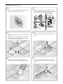
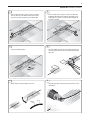
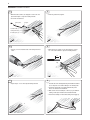
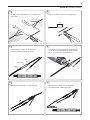
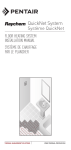
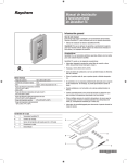
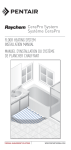
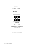
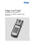
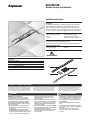
QuickNet-RK
QuickNet™ Heating Cable Repair Kit
Installation Instructions
Description
The QuickNet-RK repair kit is for repairing heating cable that is damaged
during installation of the QuickNet mat. The kit includes jumper wires to
bridge the heating element after the damaged section is removed. The kit
contents are sufficient to repair one damaged section up to 5 inches long. If
more than 5 inches of cable has been damaged, the mat must be replaced.
Tools Required
• Wire Strippers 16-26 AWG
• Gloves
• Scissors
• Heat gun (1000˚F air temp
with heat deflector required)
• Multimeter (capable of 200K ohms)
Other Required Materials
• QuickNet System Installation Manual (H57704)
• QuickStat Thermostat Installation and Operation Manual (H57725)
Optional Tile Removal Tools
• Grout removal tool
• Hammer
Approvals
Radiant Floor Heating
Kit Contents:
Item Qty Description
A
2
Jumper wires (blue)
B
6
SolderSleeve® connectors
C
4
Heat-shrinkable tubing
D
1
Ground wire (non-insulated)
A
C
B
D
WARRANTY & APPROVALS DISCLAIMER
The QuickNet-RK Repair Kit is for making minor repairs
to the QuickNet heating cable if it is damaged during or
after installation. Because the condition of the damaged
mat, site conditions and installer capability can vary,
Tyco Thermal Controls does not warrant the repair or
warrant that the repaired floor warming system will
function properly. Use of this kit voids the warranty
of the repaired portion of the heating cable. Repairs
WARNING:
WARNING: Shock and Fire Hazard.
If the QuickNet mat is damaged or not installed
properly, fire or shock could occur resulting in
serious personal injuries or damage to property. You
must carefully follow the warnings and instructions
contained in these instructions and the QuickNet
Installation Manual (H57704). Contact Tyco Thermal
Controls for assistance.
• The QuickStat thermostat must be used. It has a
ground-fault circuit interrupter (GFCI) to prevent
electric shock.
• The QuickNet-RK repair kit must be installed
by qualified personnel familiar with generally
accepted construction techniques and safe electrical
practices. The installation must comply with all
should only be attempted by a qualified electrician or
experienced craftsmen familiar with good electrical
practice and techniques for tile installation and removal.
Contact Tyco Thermal Controls for assistance.
INSTALLATION GUIDELINES:
national and local electrical codes. If you are
unfamiliar with these requirements, contact a
licensed electrician.
• Electric wiring and the heating mat are installed
in the floor. Be sure that the floor is not penetrated
by nails, screws, or similar devices that can cause
damage on first installation or during subsequent
floor repairs in the future.
• Do not use this Repair Kit to splice different QuickNet
mats together. It is designed only to repair a damaged
section of heating cable in a single mat.
• The QuickNet heating cable cannot be cut to length,
crossed over itself, or installed closer than the
spacing in the mat.
• QuickNet mats can only be installed beneath ceramic
tile or natural stone surfaces. Do not install beneath
wooden, carpeted, linoleum, or other type floors.
• Do not step directly on or damage the heating cable
during installation.
• Do not install the QuickNet mat across expansion
joints.
• Follow the manufacturer’s instructions for installing
tiles, scratch coat, thin-set mortar, or quick drying
mortar beds.
• Do not allow heating cable, cold lead, or floor
temperature sensor to cross over themselves or
each other.
2
QuickNet-RK Installation Instructions
1
2
• Turn off the power to the QuickNet floor warming system at the
circuit breaker before starting any repair work.
• Disconnect the QuickNet cold leads, power wires and floor sensor
leads from the the QuickStat Thermostat. This provides additional
safety and allows for the testing required in later steps.
Line
(black)
QuickStat®
GFCI Class A
ON ON ON ON ON
LINE L1 (L)
240/(120)VAC
L2 (N)
®
Q
G uick
FC
St
N I Cla at
E ss
LI
24
L2
Power
L1 A
(L
)
0/
(1
20
(N )V
) AC
SENSOR
LOAD
OR
NS
SE
LO
16
M A
ax
.
A
D
Hig UT
powh VolION:
er tag
sup e ply Dis
bef con
DU
ore nec
384AL VO
ser t
1920W LTA
vici
ng
0W/240VAGE
/21
50/
20V C (16 60
AC A) Hz
(16
A)
16A
Max.
Neutral
(white)
Cold
lead
Cold
lead
CA
OFF OFF OFF OFF OFF
Back of thermostat
Ground
Cold leads
Floor sensor leads
Floor sensor leads
3
4
• If the damaged section has not been installed in mortar, proceed
to Step 7.
• Once the grout is removed, carefully break away the tile using a
hammer.
• Remove the tile above the damaged section by removing the
grout with a removal tool, being careful not to further damage
the heating cable. Do not use a knife or chisel.
Heating
cable
Damage
location
5
6
• Remove any broken tile and vacuum other debris from the
exposed surface to locate the damaged heating cable section.
• To expose the damaged section, break mortar away from the
heating cable with the hammer, making sure not to damage the
cable.
3
QuickNet-RK Installation Instructions
7
8
• Remove sufficient mortar to expose 4-5 inches of heating
cable on either side of the damage. Using scissors cut the
mesh from the cable to provide room to install the splice.
• Remove at least 3 inches, and up to 5 inches of heating cable
including the damaged section leaving two protruding ends of
heating cable. If more than 5" of cable has been damaged, the
mat must be replaced.
3-5"
9
10
• Using the 16 AWG opening on the wire strippers carefully score
the outer jacket, 2 inches from the end of both exposed heating
cable ends.
• Remove the damaged section.
2"
Damaged
section
2"
11
12
• Flex the cable to break the insulation at the score.
Heating
cable
• Using the high setting on the heat gun, heat the jacket to loosen
the insulation.
Score
4
QuickNet-RK Installation Instructions
13
14
• While the cable is still hot, use strippers to remove the outer
jacket and foil layer to expose the heating elements.
• Twist two ground wires together.
• Cut off the colored thread.
Outer jacket
Foil layer
Colored thread (1)
Heating elements (2)
Grounding wire (2)
15
• Heat only 1/2" of the insulated ends of the heating elements to
soften.
16
• While the wires are still hot, use the wire strippers to remove
1/2" of the outer insulation to expose the heating elements.
1/2"
17
• Repeat steps 9 - 15 for other exposed heating cable end.
18
• Test both ends of the heating cable using this insulation resistance
test to verify there is not further damage to the heating cable.
1. Connect the ground wire to the black lead and both power
wires to the red lead of the multimeter.
2. Make sure the meter reads ‘Open’ or “OL’. If you get a different
reading, contact Tyco Thermal Controls at 800-545-6258.
3. Record these readings on the Commissioning Record (page 8).
5
QuickNet-RK Installation Instructions
19
20
• Cut jumper wires to length allowing for 1/2" overlap on each
end as shown.
• Strip 1/2" of insulation off both ends of each jumper wire.
1/2"
1/2"
1/2"
21
22
• Slide SolderSleeve connector onto one heating wire.
• Insert jumper wire into SolderSleeve connector.
• Heat SolderSleeve connectors until solder and adhesive have
melted. (The colored solder ring will turn clear when melted.)
• Allow to cool, then repeat for second jumper wire.
Heating
wire
SolderSleeve
Jumper
wire
23
• Slide two heat-shrinkable tubes onto each jumper wire.
24
• Slide SolderSleeve connector onto one heating wire.
• Insert jumper wire into SolderSleeve connector.
6
QuickNet-RK Installation Instructions
25
26
• Heat SolderSleeve connectors until solder and adhesive have
melted.
• Center the 4 black heat-shrinkable tubes over the installed
SolderSleeve connectors.
• Allow to cool, then repeat for second jumper wire.
• Using the heat gun, shrink in place.
27
28
• Cut ground jumper to length, allowing 1/2" overlap on each end
of twisted grounding wire.
• Slide SolderSleeve connectors onto ground wires and jumper.
1/2"
1/2"
29
• Heat SolderSleeve connectors until solder has melted.
30
• Before and after re-installing the mortar and tile run the three
standard QuickNet commissioning tests from the cold lead
wire at the QuickStat Thermostat and record the results in the
commissioning log.
• Continue the QuickNet System installation following the
QuickNet and QuickStat Installation manuals.
7
QuickNet-RK Installation Instructions
Once the QuickNet splice is completed, conduct the following three commissioning tests on this page and record the values on the QuickNet-RK
Commissioning Record (on page 8). Retain these readings with the original QuickNet Commissioning Record.
Testing Procedure
1 Insulation Resistance Test
2 Heating Cable Resistance Test
This test ensures that the insulating jackets of the mat are not
damaged. A low value indicates the mat has been damaged and
must be replaced.
This test measures the resistance of the mat and is used to determine circuit integrity.
Cold lead
White
Black
Ground
R = ?Ω
R = Open
or OL
See Table 1
1. Set your multimeter to the 200 ohm range.
1. Connect the ground wire to the black lead and both power
wires to the red lead of the multimeter.
2. Connect the multimeter leads to the black and white cold lead
wires.
2. Set your multimeter to the 200 K ohm range. Make sure the
meter reads ‘Open’ or “OL’. If you get a different reading,
contact Tyco Thermal Controls at 800-545-6258.
3. Compare this resistance reading to the resistance specified in
the QuickNet Resistance Table below. The value should be within ±10%. If you get a different reading, contact Tyco Thermal
Controls at 800-545-6258.
3. Record these readings on the Commissioning Record (page 8).
4. Record these readings on the Commissioning Record (page 8).
3 Sensor Resistance Test
QuickNet Mat Resistance Table
120 V QuickNet with thermostat
This test measures the resistance of the floor sensor and is
used to verify the sensor integrity.
Red
Green
R = 9 – 25 KΩ
Catalog Number
Size ft² (m²)
Resistance Ohms
QUICKNET-010-1
10 (0.9)
120
QUICKNET-020-1
20 (1.9)
60
QUICKNET-030-1
30 (2.8)
40
QUICKNET-040-1
40 (3.7)
30
QUICKNET-050-1
50 (4.6)
24
QUICKNET-060-1
60 (5.6)
20
QUICKNET-070-1
70 (6.5)
17
QUICKNET-080-1
80 (7.4)
15
QUICKNET-090-1
90 (8.4)
13
QUICKNET-100-1
100 (9.3)
12
240 V QuickNet Mats with thermostat (and without thermostat)
Catalog Number
Size ft² (m²)
Resistance Ohms
QUICKNET-050-2 (-050X-2)
50 (4.6)
96
1. Set your multimeter to the 200 K ohm range.
QUICKNET-060-2 (-060X-2)
60 (5.6)
80
2. Connect the multimeter leads to the red and green lead wires.
QUICKNET-080-2 (-080X-2)
80 (7.4)
60
QUICKNET-100-2 (-100X-2)
100 (9.3)
48
3. Make sure the meter reads between 9–25 KΩ.
If you get a different reading, contact Tyco Thermal Controls
at 800-545-6258.
4. Record these readings on the Commissioning Record (page 8).
8
QuickNet-RK Installation Instructions
QuickNet-RK Cable Repair Commissioning Record (retain this record)
Installer
Date of commissioning:
Company:
Name of installer:
Street:
City:
Postal code:
Phone (office):
Phone (mobile):
Fax:
Email:
Website:
Project data
Customer name:
Street:
City:
Sub floor type:
Room type:
Postal code:
Wood
Concrete
Floor covering:
Ceramic tile
Kitchen
Entryway
Bathroom
Other:
Rated voltage:
120 V
240 V
Natural stone
Recorded value
QuickNet mat
Catalog number:
Sensor resistance
After embedding in mortar*:
(KΩ)
After floor covering*:
(KΩ)
Before embedding in mortar*:
(Ω)
After embedding in mortar*:
(Ω)
After floor covering*:
(Ω)
Before embedding in mortar*:
(KΩ)
After embedding in mortar*:
(KΩ)
After floor covering*:
(KΩ)
* Refer to QuickNet Installation Manual (H57704) for further installation and testing details. Available online at www.tycothermal.com.
Installer:
Please leave this record with homeowner.
Tyco, QuickNet, QuickStat, Raychem and SolderSleeve are trademarks or registered trademarks of Tyco Thermal Controls LLC or its affiliates.
Worldwide Headquarters
Tyco Thermal Controls
300 Constitution Drive
Menlo Park, CA 94025-1164
USA
Tel (800) 545-6258
Fax (800) 596-5004
[email protected]
www.tycothermal.com
Canada
Tyco Thermal Controls
250 West Street
Trenton, Ontario
Canada KBV 5S2
Tel (800) 545-6258
Fax (800) 596-5004
Important: All information, including illustrations, is believed to be reliable.
Users, however, should independently evaluate the suitability of each product
for their particular application. Tyco Thermal Controls makes no warranties as
to the accuracy or completeness of the information, and disclaims any liability
regarding its use. Tyco Thermal Controls' only obligations are those in the Tyco
Thermal Controls Standard Terms and Conditions of Sale for this product, and in
no case will Tyco Thermal Controls or its distributors be liable for any incidental,
indirect, or consequential damages arising from the sale, resale, use, or misuse
of the product. Specifications are subject to change without notice. In addition,
Tyco Thermal Controls reserves the right to make changes—without notification
to Buyer—to processing or materials that do not affect compliance with any
applicable specification.
H57959
(KΩ)
Printed in USA P000000662
Heating cable resistance
Before embedding in mortar*:
© 2006 Tyco Thermal Controls LLC
Insulation resistance
07/06
Batch date (from box or cord label):