1
Operator's
Manual
®
2-Cycle
WEEDWACKER®
GAS TRIMMER
Model No. 316.791870
•
•
•
•
•
•
SAFETY
ASSEMBLY
OPERATION
MAINTENANCE
PARTS LIST
ESPANOL, R 15
CAUTION:
Before using
this product, read this
manual and follow all
safety rules and operating
instructions.
Sears, Roebuck
and Co., Hoffman
Estates, IL 60179, U.S.A.
Visit our website" www.sears.com/craftsman
769-02958
02/07
CALIFORNIA
PROPOSITION
SPARK ARRESTOR
65 WARNING
THE ENGINE EXHAUST FROM THIS PRODUCT
CONTAINS CHEMICALS KNOWN TO THE STATE OF
CALIFORNIA TO CAUSE CANCER, BIRTH DEFECTS
OR OTHER REPRODUCTIVE HARM.
TABLE OF CONTENTS
Safety Rules ....................................
Warranty .......................................
Know Your Unit .................................
Oil and Fuel Information ...........................
2
4
5
6
Assembly Instructions ............................
6
Starting/Stopping
Instructions ......................
7
Operating Instructions ............................
8
Maintenance and Repair Instructions
................
9
Cleaning and Storage ...........................
11
Troubleshooting Chart ...........................
12
Specifications
.................................
12
Parts List .....................................
28
Service Numbers ........................
Back Cover
* IMPORTANT
READ ALL INSTRUCTIONS
SAFETY
BEFORE OPERATING
• Read the instructions carefully. Be familiar with the controls
and proper use of the unit.
• Do not operate this unit when tired, ill or under the influence of
alcohol, drugs or medication.
• Children must not operate the unit. Teens must be
accompanied and guided by an adult.
• Inspect the unit before use. Replace damaged parts. Check
for fuel leaks. Make sure all fasteners are in place and secure.
Replace cutting attachment parts that are cracked, chipped or
damaged in any way.
• Use only Hassle Free TM XTRA QUIET Spiral Line. Never use
metal-reinforced line, wire, chain or rope. These can break off
and become dangerous projectiles.
• Be aware of risk of injury to the head, hands and feet.
• Clear the area to be cut before each use. Remove rocks,
broken glass, nails, wire, string and other objects which may
be thrown or become entangled in the cutting attachment.
Clear the area of children, bystanders and pets; keep them
outside a 50-foot (15 m) radius, at a minimum. Even then, they
are still at risk from thrown objects. Encourage bystanders to
wear eye protection. If you are approached, stop the unit
immediately.
• Squeeze the throttle control and check that it returns
automatically to the idle position. Make all adjustments or
repairs before using the unit.
FUEL SAFETY WARNINGS
• Store fuel only in containers specifically designed and
approved for the storage of such materials.
[,_
vapors can explode if ignited. Take the following
ARNING:
Gasoline is highly flammable and its
precautions:
NOTE
NOTE: For users on U.S. Forest Land and in the states of
California, Maine, Oregon and Washington. All U.S. Forest
Land and the state of California (Public Resources Codes 4442
and 4443), Oregon and Washington require, by law that certain
internal combustion engines operated on forest brush and/or
grass-covered areas be equipped with a spark arrestor,
maintained in effective working order, or the engine be
constructed, equipped and maintained for the prevention of
fire. Check with your state or local authorities for regulations
pertaining to these requirements. Failure to follow these
requirements could subject you to liability or a fine. This unit is
factory equipped with a spark arrestor. If it requires
replacement, ask a Sears or other qualified service dealer to
install the Accessory Muffler Assembly, Part #753-05169.
All information, illustrations, and specifications in this manual
are based on the latest product information available at the
time of printing. We reserve the right to make changes at any
time without notice.
INSTRUCTIONS
*
• Always stop the engine and allow it to cool before filling the
fuel tank. Never remove the fuel tank cap or add fuel when the
engine is hot. Never operate the unit without the fuel cap
securely in place.
• Loosen the fuel tank cap slowly to relieve any pressure in the
tank.
• Mix and add fuel in a clean, well-ventilated outdoor area where
there are no sparks or flames. Remove the fuel cap slowly, and
only after the engine stops. Do not smoke while fueling or
mixing fuel. Wipe up any spilled fuel from the unit immediately.
• Avoid creating a source of ignition for spilled fuel. Do not
start the engine until fuel vapors dissipate.
• Move the unit at least 30 feet (9.1 m) from the fueling source
and site before starting the engine. Do not smoke. Keep
sparks and open flames away from the area while adding
fuel or operating the unit.
WHILE OPERATING
• Never start or run the unit inside a closed room or building.
Breathing exhaust fumes can be fatal. Operate this unit only
in a well-ventilated outdoor area.
• Wear safety glasses or goggles that meet ANSI Z87.1
standards and are marked as such. Wear ear/hearing
protection when operating this unit. Wear a face or dust
mask if the operation is dusty.
• Wear heavy long pants, boots, gloves and a long sleeve
shirt. Do not wear loose clothing, jewelry, short pants,
sandals or go barefoot. Secure hair above shoulder level.
• The cutting attachment shield must always be in place while
operating the unit. Do not operate unit without both trimming
lines extended, and the proper line installed. Do not extend
the trimming line beyond the length of the shield.
• This unit has a clutch. The cutting attachment remains
stationary when the engine is idling. If it does not, take the unit
to a Sears or other qualified service dealer for an adjustment.
• Adjust the D-handle to your size in order to provide the best grip.
• Be sure the cutting attachment
before starting the unit.
is not in contact with anything
• Use the unit only in daylight or good artificial light.
• Avoid accidental starting. Be in the starting position
whenever pulling the starter rope. The operator and unit must
be in a stable position while starting. Refer to
Starting/Stopping Instructions.
• Use the right tool. Only use this tool for its intended purpose.
• Always hold the unit with both hands when operating. Keep a
firm grip on both handles or grips.
• Use only replacement parts or accessories recommended for
this tool that are distributed by Sears or a Craftsman outlet.
Use of any replacement parts or accessories purchased
elsewhere may be hazardous, and will also void your warranty.
• Keep unit clean of vegetation and other materials. They may
become lodged between the cutting attachment and shield.
• To reduce fire hazard, replace a faulty muffler and spark
arrestor. Keep the engine and muffler free from grass, leaves,
excessive grease or carbon build up.
OTHER SAFETY WARNINGS
• Keep hands, face, and feet away from all moving parts. Do not
touch or try to stop the cutting attachment when it rotates.
• Never store the unit with fuel in the tank, inside a building
where fumes may reach an open flame (pilot lights, etc.) or
sparks (switches, electrical motors, etc.).
• Do not touch the engine, gear housing or muffler. These parts get
extremely hot from operation, even after the unit is turned off.
• Allow the engine to cool before storing or transporting.
sure to secure the unit while transporting.
• Do not operate the engine faster than the speed needed to
cut, trim or edge. Do not run the engine at high speed when
not cutting.
• Store the unit in a dry place, secured or at a height to prevent
unauthorized use or damage. Keep out of the reach of children.
• Always stop the engine when cutting is delayed or when
walking from one cutting location to another.
• If you strike or become entangled with a foreign object, stop the
engine immediately and check for damage. Do not operate
before repairing damage. Do not operate the unit with loose or
damaged parts.
• Turn the engine to off and disconnect
maintenance or repair.
• Never douse or squirt the unit with water or any other liquid.
Keep handles dry, clean and free from debris. Clean after
each use, see Cleaning and Storage instructions (p. 11).
• Keep these instructions. Refer to them often and use them to
instruct other users. If you loan this unit to others, also loan
them these instructions.
SAVE THESE INSTRUCTIONS
the spark plug for
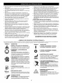
• SAFETY & INTERNATIONAL
SYMBOLS
•
This operator's manual describes safety and international symbols and pictographs that may appear on this product.
operator's manual for complete safety, assembly, operating and maintenance and repair information.
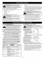
SYMBOL
MEANING
Be
SYMBOL
Read the
MEANING
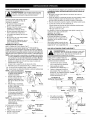
• SAFETY ALERT SYMBOL
I
Indicates danger, warning Or caution. May be used
in conjunction with other symbols or pictographs.
ill I lID
wARNING : READ OPERATOR'S MANUAL
Read the operator s manual(s)and fol!ow all warnings
and safety instructions, Failureto do so Can result in
O
• ON/OFF
STOP
CONTROL
ON / START
/ RU_
• OFF
ON/OFF
STOP CONTROL
or STOP
• HOT SURFACE WARNING
serious injury to the Operator and/oi bystanders:
Do not touch a hot muffler, gear housing or
cylinder. You may get burned. These parts get
extremely hot from operation. They remain hot for
a short time after the unit is turned off.
WEAR EYE AND HEARING PROTECTION
i_
cause severe eye injury and hearing !ossl Wear
eye
protect on
meeting
ANSI and
Z87:1
standards
WARNING:
Thrown
objects
loud
noise can
and ear protection when operating this unit. Use
a full face shield when needed.
UNLEADED
FUEL
_'_
_
_',_
_l_'
• ..
_w
_
• THROWN OBJECTS AND ROTATING
CUTTER CAN CAUSE SEVERE INJURY
/JAr
_/_t_
WARNING: Do not operate without the cutting
attach-ment shield in place. Keep away from the
rotating cutting attachment.
A!waYS use clean, fres h unleaded fue!
•OIL
_
Refer to operat0r's manual for the p[0per type 0f OiL
' SHARP BLADE
WARNING: Sharp blade on cutting attachment
shield, TO prevent serious injury, do net touch
the
ne cutt ng bade.
A
•
L_',_¢_,'_
/_,j_=fi_
-
KEEP BYSTANDERS AWAY
WARNING: Keep all bystanders, especially
children and pets, at least 50 feel (15 m) from
the operating area.
CRAFTSMAN
TWO-YEAR
LIMITED
WARRANTY
If this Craftsman product fails due to a defect in material or workmanship within two years from the date of purchase, return it to any
Sears store, Sears Service Center, or other Craftsman outlet in the United States for free repair. This warranty does not include:
•
Expendable items which can wear out from normal use within the warranty period, such as cutting line, air cleaner or spark plug.
•
Repairs necessary because of operator abuse or negligence and the failure to operate or maintain the equipment according to all
supplied instructions.
This warranty applies for only 90 days if this product is ever used for commercial or rental purposes. This warranty applies only while
this product is used in the United States. This warranty gives you specific legal rights, and you may also have other rights which vary
from state to state.
Sears, Roebuck and Co., Hoffman Estates, IL 60179
Owner's Warranty Responsibilities
• As the small off-road engine owner, you are responsible for the performance of the required maintenance listed in your operator's
manual. Sears recommends that you retain all receipts covering maintenance on your small off-road engine, but Sears cannot deny
warranty solely for the lack of receipts or for your failure to ensure the performance of all scheduled maintenance.
• As the small off-road engine owner, you should however be aware that Sears may deny you warranty coverage if your small off-road
engine or a part has failed due to abuse, neglect, improper maintenance or unapproved modifications.
• You are responsible for presenting your small off-road engine to a Sears authorized service center as soon as problem exists. The
warranty repairs should be completed in a reasonable amount of time, not to exceed 30 days.
If you have any questions regarding your warranty rights and responsibilities,
Manufacturer's
• The warranty period begins on the date the engine or equipment
Warranty
you should call 1-800-4-MY-HOME
®.
Coverage
is delivered to the retail purchaser.
• The manufacturer warrants to the initial owner and each subsequent purchaser, that the engine is free from defects in material and
workmanship which cause the failure of a warranted part for a period of two years.
• Repair and replacement of warranted part will be performed at no charge to the owner at an authorized
the nearest location please contact Sears at: 1-800-4-MY-HOME
®.
Sears service center. For
• Any warranted part which is not scheduled for replacement, as required maintenance or which is scheduled only for regular
inspection to the effect of "Repair or Replace as Necessary" is warranted for the period. Any warranted part which is scheduled for
replacement as required maintenance will be warranted for the period of time up to the first scheduled replacement point for that
part.
• The owner will not be charged for diagnostic labor which leads to the determination
diagnostic work is performed at an authorized Sears Service Center.
• The manufacturer is liable for damages to other engine components
• Failures caused by abuse, neglect or improper maintenance
that a warranted
caused by the failure of a warranted
if the
part still under warranty.
are not covered under warranty.
• The use of add-on or modified parts can be grounds for disallowing a warranty claim. The manufacturer
of warranted parts caused by the use of add-on or modified parts.
• In order to file a claim, go to your nearest authorized
authorized Sears Service Centers.
part is defective
Sears Service Center. Warranty
is not liable to cover failures
service or repairs will be provided
at all
• Any manufacturer approved replacement part may be used in the performance of any warranty maintenance or repair of emission
related parts and will be provided without charge to the owner. Any replacement part that is equivalent in performance or durability
may be used in non-warranty maintenance or repair and will not reduce the warranty obligations of the manufacturer.
• The following components are included in the emission related warranty:
up/fuel filter, ignition module, spark plug and muffler.
engine, air filter, carburetor,
primer, fuel lines, fuel pick
FuelCap
On/Off Stop Control
StarterRope
Grip
D-Handle
Throttle Control
Primer
Bulb
Shoulder Strap
Loop
Knob
Line Cutting
Blade
EZ Fire TM
Lever
Air Filter/Muffler
Cover
Convertible
Coupler
Shaft Housing
TM
Muffler
Spark Plug
APPLICATIONS
As a trimmer:
•
Cutting grass and light weeds.
•
Edging
•
Decorative trimming around trees, fences, etc.
Other optional accessories may be used with this unit.
Cutting
Attachment
Shield
Hassle Free IV®
Cutting Attachment
OIL AND FUEL MIXING INSTRUCTIONS
Old and/or improperly mixed fuel are the main reasons for the unit
not running properly. Be sure to use fresh, clean unleaded fuel.
Follow the instructions carefully for the proper fuel/oil mixture.
Definition of Blended Fuels
Today's fuels are often a blend of gasoline and oxygenates
such as ethanol, methanol, or MTBE (ether). Alcohol-blended
fuel absorbs water. As little as 1% water in the fuel can make
fuel and oil separate. It forms acids when stored. When using
alcohol-blended fuel, use fresh fuel (less than 60 days old).
Using Blended Fuels
If you choose to use a blended fuel, or its use is unavoidable,
follow recommended precautions:
• Always use the fresh fuel mix explained in your operator's manual
• Always agitate the fuel mix before fueling the unit
• Drain the tank and run the engine dry before storing the unit
Using Fuel Additives
The bottle of 2-cycle oil that came with your unit contains a fuel
additive which will help inhibit corrosion and minimize the
formation of gum deposits. It is recommended that you use our 2cycle oil with this unit. If unavailable, use a good 2-cycle oil designed for air-cooled engines along with a fuel additive, such as
STA-BIL ®Gas Stabilizer or an equivalent. Add 0.8 oz. (23 ml.) of
fuel additive per gallon of fuel according to the instructions on the
container. NEVER add fuel additives directly to the unit's fuel tank.
Thoroughly mix the proper
ratio of 2-cycle engine oil
with unleaded gasoline in
a separate fuel can. Use a
40:1 fuel/oil ratio. Do not
mix them directly in the
UNLEADED GAS
2-CYCLE OIL
engine fuel tank. See the
UNLEADED GAS 2 CYCLE OIL
table below for specific
gas and oil mixing ratios.
f GALLON US
3.2 FL. OZ.
(3.8 LITERS)
195 ml)
NOTE: One gallon (3.8
1 LITER
25 ml
liters) of
unleaded
MIXING RATIO - 40:1
gasoline mixed
with one 3.2 oz. (95 ml.) bottle of 2-cycle oil makes a
40:1 fuel/oil ratio.
NOTE:
Dispose of the old fuel/oil mix in accordance to
Federal, State and Local regulations.
Ignited vapors may explode. Always stop the engine
and allow it to cool before filling the fuel tank. Do not
smoke while filling
the tank.
Keep sparks
and open
WARNING:
Gasoline
is extremely
flammable.
flames at a distance from the area.
from fuel spray. Never operate the unit without the
fuel cap securely
in place.
[,_[WARNING:
Remove
fuel cap slowly to avoid injury
I
maximum reliability, pay strict attention to the oil and I
fuel mixing instructions on the 2-cycle oil container.
CAUTION:
For proper engine operation and
the
engine.
Us ng
mpropery m xed fue can severey damage
'_1
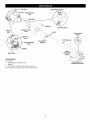
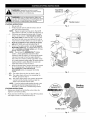
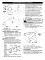
INSTALL AND ADJUST THE D-HANDLE
WARNING:
Add fuel in a clean, well ventilated
I
outdoor area. Wipe up any spilled fuel immediately.
Avoid creating a source of ignition for spilt fuel. Do
not start the engine until fuel vapors dissipate.
I
Install
INSTALL LINE TRIMMER
ATTACHMENT
1. Place D-handle the over the shaft housing and onto the
bottom clamp (Fig. 1). Place it a minimum of 6 inches (15.24
cm) from the end of the shaft grip.
NOTE: To make installation easier,
place the unit on the ground or
on a workbench.
1.
On/Off Stop Control
(4) Screws
Shaft
Housing
Shaft Grip
Minimum 6
(15.24 cm)
Bottom Clamp
Fig. 1
2. Start screws with a flat-head or T-25 Torx screwdriver. Do not
tighten until handle is adjusted.
Adjust
3. While holding the unit in the operating position (Fig. 2), position
the D-handle to the location that provides you the best grip.
4. Tighten the clamp screws evenly until the D-handle is secure.
Turn knob counterclockwise to
loosen coupler (Fig. 11, p. 8).
2.
While firmly holding attachment,
push it straight into the coupler
until the release button snaps into
the primary hole (Fig. 12, p. 8).
NOTE: Aligning the release button
with the guide recess (Fig. 12, p.
8) will help installation.
3. Turn the knob clockwise to
tighten (Fig. 13, p. 8).
LINE TRIMMER APPLICATIONS
_,
-_4J¢
Fig. 2
Cutting grass and light weeds; edging; and decorative
around trees, fences, etc.
trimming
ventilated outdoor area. Carbon monoxide exhaust
fumes can be lethal
in athis
confined
area.
,_[WARNING:
Operate
unit only
in a well-
Stop/Off (0)
Start/On _
you are in the starting position when pulling the starter
rope
(Fig. 5). To
avoidaccidental
serious injury,
the operator
and
WARNING:
Avoid
starting.
Make sure
unit must be in a stable position while starting.
Throttle Control
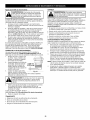
STARTING INSTRUCTIONS
Mix gas with oil.
Fill the fuel tank with the fuel/oil mixture. See Oil
and Fuel Mixing Instructions.
NOTE: There is no need to turn the unit on. The On/Off
Stop Control is in the ON ( I ) position at all times (Fig. 3).
.......................
3. Fully press and release the primer bulb 10 times,
slowly. Some amount of fuel should be visible in
the primer bulb and fuel lines (Fig. 4). If you can't
see fuel in the bulb, press and release the bulb as
many times as it takes before you can see fuel in it.
Fig. 3
1.
2.
Primer
Bulb __
4.
::
::
:::
:
ii
i!
....
H
....q
q
Push the red EZ-Fire TM lever towards the primer
bulb until it clicks and locks into place (Fig. 4).
5. Crouch in the starting position and do not squeeze
the throttle control (Fig. 5). Pull the starter rope out
with a controlled and steady motion up to 10 times.
Repeat until the engine starts.
NOTE: The unit uses the INCREDI-PULU M starting
system , which significantly reduces the effort
required to start the engine. You must pull the starter
rope out far enough to hear the engine attempt to
start. There is no need to pull the rope briskly-- there
is no harsh resistance when pulling. Be aware that this
starting method is vastly different from (and much
easier than) what you may be used to.
6. When the engine starts, squeeze the throttle control
for 15 to 30 seconds. This will warm up the unit.
The red EZ-Fire TM lever will click off
automatically
when you squeeze the throttle
control.
Red EZ-Fire
Lever
TM
Fig. 4
..........IF...
IF...
The engine does not start, go back to step 3.
The engine stops while you are squeezing the
throttle, go back to step 4.
IF... The engine stops before you squeeze the throttle
control, hold the throttle control and pull the
starter rope until the trimmer starts.
NOTE: If you are having trouble starting the unit or are
operating in extreme temperatures (below 40 ° F,
above 90 o F), refer to the Troubleshooting section.
STOPPING INSTRUCTIONS
1. Release your hand from the throttle control. Allow the
engine to cool down by idling.
2.
Press and hold On/Off Stop Control in the OFF (O) position
until engine comes to a complete stop (Fig. 3).
Starting
Position
Incredi-Pull
Starting
Throttle Control
Fig. 5
TIPS FOR BEST TRIMMING
body protection to reduce the risk of injury when
WARNING:
operating this Always
unit. wear eye, hearing, foot and
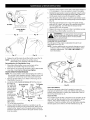
HOLDING THE TRIMMER
Before operating the unit, stand in
the operating position (Fig. 6). Check
for the following:
• The operator is wearing eye
protection and proper clothing
• With a slightly-bent right arm, the
operator's hand is holding the
shaft grip
• The operator's left arm is slightly
bent, the left hand holding the Dhandle
• The unit is at waist level
• The cutting attachment is parallel to
the ground and easily contacts the
grass without the need to bend over
LINE REPLACEMENT
"_
Fig. 6
for Hassle-Free TM Cutting Head
Always use Craftsman Hassle-Free TM XTRA QUIET Spiral Line.
Choose the line size best suited for the job at hand. Red colored
line is designed for cutting grass and small weeds. Black colored
line is designed for cutting larger weeds and light brush.
NOTE: Before inserting new line into the holes in the cutting
head, identify the proper holes. Follow directions as shown
on the line glide plate. Do Not attempt to remove the
cutting head from the unit when replacing line.
1. Remove the old line and line glide plate from the cutting head.
2. Clean entire surface of cutting head. Note positions "A"
and "B" on the cutting head.
3. Reinstall line glide plate (Fig.
7). Align arrow with:
Cutting
Line Glide
"A" when using medium (red) or
large (black) line, or
"B" when using lines with
diameters smaller than
medium (red)line
NOTE: Line glide plate must be
reinstalled in cutting head
before inserting new line.
Fig. 7
4. Insert both ends of your
line through the proper
holes in the side of the
Positioning
cutting head (Fig. 8).
Tunnel
5. Pull the line and make
sure the line is against the
hub and is fully extended
through the positioning
tunnels (Fig. 9).
Fig. 8
6. Correctly installed line will
be the same length on
both sides.
Line against
NOTE: Do not rest the
Hassle-Free TM Cutting
_
the hub
Head on the ground
while the unit is running.
J
Positioning
Tunnel
Some line breakage will occur
from:
Fig. 9
• Entanglement with foreign
matter
• Normal line fatigue
• Attempting to cut thick, stalky weeds
• Forcing the line into objects such as walls or fence posts
RESULTS
• Keep the cutting attachment parallel to the ground.
• Cut from left to right whenever possible. Cutting to the right
improves the unit's cutting efficiency. Clippings are thrown
away from the operator.
• Trim only when grass and weeds are dry.
• The life of your cutting line is dependent upon:
- Following the trimming tips
- What vegetation is being cut
- Where vegetation is being cut
DECORATIVE TRIMMING
Decorative trimming is
accomplished by removing all
vegetation around trees, posts,
30°.
fences and more. Rotate the
whole unit so that the cutting
attachment is at a 30 ° angle to the
ground (Fig. 10).
USING THE CONVERTIBLE TM COUPLER
Fig. 10
I
WARNING:
Before you begin using any
attachment, read and understand the manual that
came with the add-on. Follow all safety
information contained within.
I
I
You can convert this unit to edge grass. 90° Edging Hole
1. Make sure the unit is turned
(Trimmer Only)
completely off.
2. Turn the knob counterclockwise
to loosen coupler (Fig. 11).
3. Push in the release button (Fig. 12)
and twist the shaft 90 ° until the
release button snaps into the 90 °
hole (Fig. 11).
Knob
4. Turn the knob clockwise to lock
the coupler (Fig. 13).
Fig. 11
Convertible
TM
Coupler
Primary
Hole
_
Release Button
Guide
Knob _s___j
Recess
Fig. 12
Upper Shaft
__
Attachment
Housing _
Housing
_
l_
--
I
Fi . 13
CAUTION:
Before operating this unit, be sure
I
that the release button is fully snapped into the
primary hole (Fig. 12), and that the knob (Fig. 13) is
securely tightened.
I
Craftsman Convertible TMFeature
To Install Attachments
The coupler allows you to convert this unit for use with the
following add-on attachments:
•
Cultivator
•
Blade Edger
•
Blower
•
Brush Cutter
•
Pruner
NOTE: To make installation easier, place the unit on the ground
or on a workbench.
damage to the unit, shut the unit off before
WARNING:
To avoid add-ons.
serious personal injury and
removing or installing
1.
2.
3.
4.
,_
Make sure the unit is turned completely off.
Turn the knob counterclockwise to loosen the coupler (Fig. 11).
While firmly holding the add-on, push it straight into the
coupler until the release button (Fig. 12) snaps into the
primary hole (Fig. 12). The primary hole is on the opposite
side of the coupler from the knob (Fig. 12). Align the release
button with the Guide Recess (Fig. 12) to help installation.
Turn the knob clockwise to tighten (Fig. 13).
snapped
primary
holeattachments
only. Using the
CAUTION:into the
These
add-on
are wrong
to be
I
hole could lead to personal injury or damage to the unit.
To Remove Attachments
1.
2.
3.
4.
MAINTENANCE
SCHEDULE
Make sure the unit is turned completely off.
Turn the knob counterclockwise to loosen the coupler (Fig. 11).
Press and hold the release button (Fig. 12).
While firmly holding the upper shaft housing (Fig. 13), pull
the attachment out of the coupler.
AIR FILTER MAINTENANCE
WARNING:
To prevent serious injury, never
I
perform maintenance or repairs with unit running.
I
Always service and repair a cool unit. Disconnect the
spark plug wire to ensure that the unit cannot start.
WARNING:
To avoid serious personal injury,
always turn your unit off and allow it to cool before
clean or service it.
Perform these required maintenance procedures at the frequency
stated in the table. These procedures should also be a part of any
seasonal tune-up.
NOTE: Some maintenance procedures may require special
tools or skills. If you are unsure about these procedures
take your unit to any non-road engine repair
establishment, individual or authorized service dealer. Call
1-800-4-MY-HOME ® for more information.
Removing the Air Filter/Muffler
1. Remove the four (4) screws
securing the air filter/muffler
cover (Fig, 14). Use a flat
blade or T20 Torx bit
screwdriver.
2. Pull the cover from the
engine, Do not force.
NOTE: Maintenance, replacement, or repair of the emission
control devices and system may be performed by a Sears
or other qualified service dealer. Call 1-800-4-MY-HOME ®
for more information.
Cleaning the Air Filter
Failure to maintain your air filter
properly can result in poor
performance or can cause
permanent damage to your
engine.
1. Remove air filter/muffler
cover. Refer to Removing
the Air Filter/Muffler Cover
above,
In order to assure peak performance of your engine, inspection of the
engine exhaust port may be necessary after 50 hours of operation. If
you notice lost RPM, poor performance or general lack of
acceleration, this service may be required. If you feel your engine is in
need of this inspection, refer service to a Sears or other qualified
service dealer. Call 1-800-4-MY-HOME _ for more information. DO
NOT attempt to perform this process yourself as engine damage may
result from contaminants involved in the cleaning process for the port.
FREQUENCY
MAINTENANCE
REQUIRED
SEE
Before star_ing
engine
Fill fuel tank with fresh fuel
p. 6
Every 10 hours
Clean and re-oil air filter
p. 9 & 10
Every 25 hours
Check and clean spark arrestor
Check spark plug condition and gap
p. 10
p. 11
Every 50 hours
Inspect exhaust port and spark
arrestor screen for clogging or
obstruction
p. 10
Cover
Screws
Fig. 14
2. Turn cover over and look inside to locate the air filter. Remove
the air filter from inside the air filter/muffler cover (Fig, 15).
3. Wash the filter in detergent and water (Fig. 16). Rinse the filter
thoroughly, Squeeze out excess water, Allow it to dry completely.
4. Apply enough clean SAE 30 oil to lightly coat the filter (Fig, 17).
5. Squeeze the filter to spread and remove excess oil (Fig. 18).
I
4. Clean the spark arrestor screen with a wire brush. Replace it
if it is damaged, or if you are unable to clean it thoroughly.
5. Reinstall the spark arrestor screen by putting the "raised" portion
of the screen inside the recessed hole of the muffler. Make sure
that the spark arrestor screen fits flat against the muffler.
6. Place the spark arrestor plate on top of the spark arrestor screen
with the raised side up and the opening facing toward the engine
(Fig. 19)
7. Place the spark arrestor hood on top of the spark arrestor
plate with the "raised" side up and the opening facing AWAY
from the engine (Fig. 19). Verify that the exhaust will be
directed AWAY from the engine.
8. Replace the screw you removed in Step 2 and tighten securely.
Air Filter
Cover
Fig. 15
9. Reinstall the air filter/muffler
Fig. 16
_
arrestor screen are not tightened securely, they could
the sparkto arrestor
hoodpossible
and spark
fallARNING:
off causing Ifdamage
the unit and
serious personal injury.
CARBURETOR
ADJUSTMENT
The idle speed of the engine
filter/muffler cover (Fig. 20).
NOTE: Careless adjustments
Contact a Sears or other
carburetor adjustments.
more information.
Fig. 17
cover (Fig. 14).
is adjustable through the air
can seriously damage your unit.
qualified service dealer to make
Call 1-800-4-MY-HOME
® for
Fig. 18
6. Replace the air filter inside the air filter/muffler cover (Fig. 15).
NOTE: Operating the unit without the air filter and air
filter/muffler cover assembly will VOID the warranty.
,I
Reinstalling the Air Filter/Muffler Cover
1. Place the air filter/muffler cover over the back of the
carburetor and muffler. Align the screw holes.
2. Insert the four (4) screws into the holes in the air filter/muffler
cover (Fig. 14) and tighten. Do not over tighten.
SPARK ARRESTOR MAINTENANCE
NOTE: Pay close attention when disassembling the muffler so
you can put it back together correctly. Failure to do so will
damage the unit and may cause serious personal injury.
1. Remove air filter/muffler cover. Refer to Removing the Air
Filter/Muffler Cover (p. 9).
2. Locate the muffler, but do not remove it. Find the screw on
the bottom of
Spark Arrestor
Slots
To Engine
the muffler (Fig.
Hood
19). This screw
holds the Spark
Arrestor Hood
Assembly and
the spark
arrestor screen
Spark Arrestor
to the bottom of Screw_
the muffler.
Tabs
Screen
Muffler
Remove this
screw using
Fig. 19
either a Torx
T20 or flat blade screwdriver.
Idle
Speed
Screw
Fig. 20
Check
Fuel Mixture
Old and/or improperly mixed fuel is usually the reason for
improper unit performance. Drain and refill the tank with fresh,
properly-mixed fuel prior to making any adjustments. Refer to
Oil and Fuel Information (p. 6).
Clean Air Filter
The condition of the air filter is important to the operation of the
unit. A dirty air filter will restrict air flow and change the air/fuel
mixture. This is often mistaken for an out of adjustment
carburetor. Check the condition of the air filter before adjusting
the idle speed screw. Refer to Air Filter Maintenance (p. 9).
3. Using a small flat blade screwdriver, carefully pry up the
spark arrestor screen from the recessed hole, taking care to
notice that the "raised" part of the spark arrestor screen is
inside the recessed hole. Remove the spark arrestor screen
from the muffler.
10
I
I
AdjustIdleSpeedScrew
WARNING:
The
CLEANING
cutting attachment may spin
during idle speed adjustments. Wear protective
clothing and observe all safety instructions to
}revent serious personal injury.
_
Release the throttle trigger and let the engine idle. If the
engine stops, insert a small phillips or flat blade
screwdriver into the hole in the air filter/muffler cover (Fig.
20). Turn the idle speed screw in, clockwise, 1/8 of a turn
at a time (as needed) until the engine idles smoothly.
• Never store a fueled unit where fumes may reach an open
flame or spark.
• Allow the engine to cool before storing.
• Store the unit locked up to prevent unauthorized use or damage.
• Store the unit in a dry, well-ventilated area.
• Store the unit out of the reach of children.
LONG TERM STORAGE
3.
If the engine appears to be idling too fast, turn the idle
speed screw counterclockwise
1/8 of a turn at a time (as
needed), to reduce idle speed.
Checking the fuel mixture, cleaning the air filter, and adjusting
the idle speed should solve most engine problems. If not, have
the carburetor adjusted by a Sears or other qualified service
dealer. Call 1-800-4-MY-HOME
® for more information.
If you plan on storing the unit for an extended time, use the
following storage procedure:
1.
Carefully drain the fuel tank by running the unit dry or remove
fuel cap and tip the motor housing over and drain oil/gas fuel
into a container with the same 2-cycle fuel mixture. Do not
use fuel that has been stored for more than 60 days.
2.
Start the engine and allow it to run until it stalls. This
ensures that all fuel has been drained from the carburetor.
REPLACING THE SPARK PLUG
Use a Champion RDJ7Y spark plug
or equivalent. Remove the plug
after every 25 hours of operation
and check its condition.
r-_ _._
1.
Stop the engine and allow it to
cool. Grasp the plug boot
0.025 in.
firmly and pull it from the spark (0 635 mm
plug.
2.
Clean around the spark plug.
Remove the spark plug from
the cylinder head by turning a
5/8-inch socket counterclockwise.
3.
I
Use a small brush to clean off the outside of the unit. Do not
use strong detergents. Household cleaners that contain
aromatic oils such as pine and lemon, and solvents such as
kerosene, can damage plastic housing or handle. Wipe off any
moisture with a soft cloth.
STORAGE
If, after checking the fuel mixture and cleaning the air filter, the
engine still will not idle, adjust the idle speed screw as follows:
1. Start the engine and let it run at a high idle for a minute to
warm up. Refer to Starting/Stopping
Instructions (p. 7).
2.
always turn your trimmer off and allow it to cool
ARNING:
To or
avoid
serious
before
you clean
maintain
it. personal injury,
_
3.
Allow the engine to cool. Remove the spark plug and put 1
oz. (30 ml) of any high quality motor oil or 2-cycle oil into
the cylinder. Pull the starter rope slowly to distribute the oil.
Reinstall the spark plug.
NOTE: Remove the spark plug and drain all of the oil from the
cylinder before attempting to start the trimmer after storage.
4. Thoroughly clean the unit and inspect it for any loose or
damaged parts. Repair or replace damaged parts and tighten
loose screws, nuts or bolts. The unit is ready for storage.
_tFig. 21
Replace a cracked, fouled or dirty spark plug. Set the air
gap at 0.025 in. (0.635 mm) using a feeler gauge (Fig. 21).
spark plug electrodes. Grit in the engine could
De net sandblast,scrapeor clean
the cylinder.
[_,IWARNING:
damage
4.
Install a correctly-gapped spark plug in the cylinder head.
Tighten by turning the 5/8-inch socket clockwise until snug.
If using a torque wrench, torque to:
110-120 in.olb. (12.3-13.5 Nom). Do not over-tighten.
5. Reattach the plug boot.
TRANSPORTING
* Allow the engine to cool before transporting.
* Drain fuel from unit.
* Tighten fuel cap before transporting.
* Secure the unit while transporting.
11
PROBLEM
Empty fuel tank
Primer bulb wasn't pressed enough
Engine is flooded
Old or improperly mixed fuel
Fouled spark plug
Plugged spark arrestor
The outside temperature is below 40 ° F
The outside temperature is above 90 ° F
SOLUTION
Fill fuel tank with properly mixed fuel
Press primer bulb fully and slowly 10 times
Pull the starter rope while holding the throttle control
Drain gas tank and add fresh fuel mixture
Replace the spark plug
Clean or replace spark arrestor
Pull the starter rope up to 10-15 times
Pull the Starter rope up to 10-15 times
I=1_[_.I_1=LvAvAIHIN
I_[e]l/llm]lil=l
Air filter is plugged
Old or improperly mixed fuel
Improper carburetor adjustment
Replace or clean the air filter
Drain gas tank and add fresh fuel mixture
Adjust according to the Carburetor Adjustments
service dealer for an adjustment
Old or improperly mixed fuel
Improper carburetor adjustment
Drain gas tank and add fresh fuel mixture
Adjust according to the Carbureter Adjustments section or take toan
service dealer for an adjustment
Stop the engine and clean the cutting attachment
Clean or replace the air filter
Clean or replace spark arrestor
Cutting attachment bound with grass
Dirty air filter
Plugged spark arrestor
Old or improperly mixed fuel
Air filter is plugged
Improper carburetor adjustment
Fouled spark plug
Plugged spark arrestor
Drain gas tank and add fresh fuel mixture
Replace or Clean air filter
Adjust according to the Carburetor Adjustments
service dealer for an adjustment
Replace the spark plug
Clean or replace spark arrestor
section or take to an authorized
authorized
section or take to an authorized
NOTE: For repairs beyond the minor adjustments listed above, contact your nearest Sears Parts & Repair center (1-800-4-MY-HOME
or other qualified service dealer.
®)
Engine Type .................................................................................................................................................................
Air-Cooled, 2-Cycle
Displacement .................................................................................................................................................................
31.5 cc (1.95 cu in.)
Idle Speed RPM ..............................................................................................................................................................
2,600 - 3,600 rpm
Operating RPM ..........................................................................................................................................................................
6,800+ rpm
Ignition Type .....................................................................................................................................................................
Electronic Ignition
Ignition Switch ......................................................................................................................................................................
Rocker Switch
Spark Plug Gap ...........................................................................................................................................................
0.025 in. (0.635 mm)
Spark Plug ...........................................................................................................................................
Champion RDJ7Y or equivalent plug
Lubrication ...........................................................................................................................................................................
Fuel/Oil Mixture
Fuel/Oil Ratio .........................................................................................................................................................................................
40:1
Carburetor ...............................................................................................................................................................
Diaphragm, All-Position
Starter ...................................................................................................................................................
Incredi-Pull TM Starting Auto Rewind
Muffler .............................................................................................................................................................................
Baffled with Guard
Throttle .......................................................................................................................................................................
Manual Spring Return
Fuel Tank Capacity ...............................................................................................................................................................
13 oz. (384 ml)
Drive Shaft Housing ........................................................................................................................
Steel Tube (Craftsman Convertible TM)
Throttle Control ...............................................................................................................................................................
Finger-Tip Trigger
Approximate Unit Weight (No fuel, with Hassle Free IV®, shield, and D-handle) ...................................................................
14 Ibs. (6 kg)
Cutting Mechanism ......................................................................................................................................................
Hassle Free TM Head
Trimming Line Diameter .................................................................................................................
Hassle Free TM XTRA QUIET Spiral Line
Cutting Path Diameter .......................................................................................................................................................
17 in. (43.18 cm)
* All specifications
without notice.
are based on the latest product information
available at the time of printing. We reserve the right to make changes at any time
12
RepairProtection
Agreements
Convenios
Congratulations on making a smart purchase. Your new
Craftsman ® product is designed and manufactured for years of
dependable operation.
Felicidades por haber hecho una compra inteligente. Su nuevo
producto Craftsman esta diseSado y fabricado para que opere
de manera confiable durante aSos. Pero como todos los
productos, pudiera necesitar una reparaci6n cada cierto
tiempo. Por eso el tener un Convenio de Cobertura de Gastos
para Reparaciones puede ahorrarle dinero y disgustos.
But like all products, it may require repair from time to time.
That's when having a Repair Protection Agreement can save
you money and aggravation,
Here's what's included in the Agreement:
He aquf Io que incluye el Convenio:
Expert service by our 12,000 professional repair specialists
- Servicio proporcienado
por nuestros 12.000 especialistas
expertos en reparaciones profesionales
Unlimited service and no charge for parts and labor on all
covered repairs
- Servicio ilimitado sin cargos por piezas ni mano de obra,
en todas las reparaciones cubiertas
if your covered product can't be fixed
Discount of 10% from regular price of service and servicerelated parts not covered by the agreement; also, 10% off
regular price of preventive maintenance check
Fast help by phone - phone support from a Sears
technician on products requiring in-home repair, plus
convenient repair scheduling
Once you purchase the Agreement, a simple phone call is all
that it takes for you to schedule service. You can call anytime
day or night, or schedule a service appointment online.
-
Reemplaze del producto,
pueden arreglarse
si sus productos
cubiertos no
-
Descuento de110% del precio regular del servicio y de
piezas relacionadas con el servicio no cubiertas por el
convenio; ademas, descuento del 10% del precio regular
de los chequeos de mantenimiento preventivo
- Ayuda r_pida per tel_fono: apoyo telef6nico por parte de
un tecnico de Sears en los productos que requieren
reparaci6n en el hogar, ademas de la programaci6n de la
reparaci6n a una hora conveniente
Una vez que usted adquiera el Convenio, basta con una
Ilamada telef6nica para programar el servicio. Usted puede
Ilamar a cualquier hora del dfa o de la noche, o programar pot
Internet una cita para el servicio,
Sears has over 12,000 professional repair specialists, who have
access to over 4,5 million quality parts and accessories, That's
the kind of professionalism you can count on to help prolong
the life of your new purchase for years to come, Purchase your
Repair Protection Agreement today!
Sears tiene mas de 12.000 especialistas en reparaciones
profesionales, que tienen acceso amas de 4,5 millones de
piezas y accesorios de calidad. Ese es el tipo de
profesionalismo con el que usted puede contar para ayudar a
prolongar la vida Qtil de su nueva adquisici6n durante aSos.
iAdquiera hoy mismo su Convenio de Cobertura de Gastos
para Reparaciones!
Some limitations and exclusions apply,
For prices and additional information
Sears Installation Service
de Gastos para Reparaciones
Adquiera un Convenio de Cobertura de Gastos para
Reparaciones ahora y prot6jase de problemas y gastos
inesperados.
Purchase a Repair Protection Agreement now and protect
yourself from unexpected hassle and expense,
Product replacement
de Cobertura
call 1-800-827-6655,
For Sears professional installation of home appliances, garage
door openers, water heaters, and other major home items, in
the U.S.A. call 1-800-4-MY-HOME
®
Se aplican algunas limitaciones
y exclusiones. Para precios
e informaci6n
adicional, Ilame al 1-800-827-6655.
Servicio de Instalaci6n de Sears
Para la instalaci6n por parte de profesionales de Sears de
efectos electrodomesticos;
abridores de puertas de garaje,
calentadores de agua y demas articulos domesticos de mayor
cuantia, en los EE.UU., Ilame al 1-800-4-MY-HOME
®.
13
14
Manual
del Operador
®
2-Tiempos
WEEDWACKER®
RECORTADOR
A GASOLINA
Model No. 316.791870
•
•
•
•
•
SEGURIDAD
MONTAJE
FUNCIONAMIENTO
MANTENIMIENTO
LISTADO DE PIEZAS
PRECAUCION:
Lea el
manual del operador y siga
todas las advertencias e
instrucciones de seguridad.
Sears, Roebuck
and Co., Hoffman
Estates, IL 60179, U.S.A.
Vaya a: www.sears.com/craftsman
769-02958
02/07
PROPOSICION
65 DE CALIFORNIA
PARACHISPAS
NOTA: Para los usuarios en tierras forestales de los EE.UU.
y en los estados
de California,
Maine,
Oregon
y
Washington. Todos los terrenos forestales de los EE.UU. y el
estado de California (C6digos de Recursos Pt]blicos 4442 y
4443), Oregon y Washington,
requieren por decreto,
que
ciertos motores de combusti6n interna que se hagan funcionar
en zonas boscosas y/o zonas cubiertas por pastizales, esten
equipados con un parachispas, que sean mantenidos en buen
estado de funcionamiento o que el motor sea construido, este
equipado y sea mantenido para evitar incendios. Consulte los
reglamentos pertinentes a esos requisitos con las autoridades
estatales o locales. El incumplimiento de esos requisitos puede
responsabilizarle
o someterle a la imposici6n de una multa.
Esta unidad fue equipada en la fabrica con un parachispas.
Si requiere sustituci6n,
hay una Pantalla
Parachispas
disponible,
Pieza #753-05169 al contactar el departamento de
servicio.
LAS EMISIONES DEL MOTOR DE ESTE PRODUCTO
CONTIENEN SUBSTANCIAS QUIMICAS QUE EL
ESTADO DE CALIFORNIA CONOCE COMO
CAUSANTES DECANCER, DEFECTOS DE
NACIMIENTO U OTROS DAI_IOS REPRODUCTIVOS.
INDICE DE CONTENIDOS
Normas para una operaci6n segura ................
16
Garantia ......................................
18
Conozca su unidad .............................
19
Informaci6n del aceite y del combustible
............
20
Instrucciones de montaje .........................
20
Instrucciones de arranque y apagado ...............
21
Instrucciones de operaci6n .......................
22
Instrucciones de mantenimiento y reparaci6n .........
23
Limpieza y almacenamiento
......................
25
Resoluci6n de problemas ........................
26
Especificaciones
...............................
26
Lista de piezas .................................
28
Numeros de servicio ...................
Contraportada
• IMPORTANTE
Toda la informaci6n,
las ilustraciones
contenidas en este manual se basan
reciente disponible en el momento de
Nos reservamos el derecho de hacer
momento sin aviso previo.
INFORMACION
LEA TODAS LAS INSTRUCCIONES ANTES DE LA OPERACION
• Lea todas las instrucciones con cuidado. Conozca bien los
controles y el uso correcto de la unidad.
• No opere esta unidad siesta cansado, enfermo, o bajo los
efectos del alcohol, drogas o medicamentos.
• Los ni_os y los adolescentes menores de 15 a_os no deben
operar las unidades, excepto por los adolescentes guiados
pot un adulto.
• Inspeccione la unidad antes de utilizada. Cambie las partes
daSadas. Verifique si existen perdidas de combustible.
Aseg0rese de que los sujetadores esten bien colocados y
asegurados. Cambie las partes accesorias de corte que esten
quebradas, cascadas o da_adas de cualquier forma. Aseg0rese
de que el accesorio de corte esta bien instalado y ajustado con
firmeza. AsegOrese de que la protecci6n accesoria de corte este
bien conectada y colocada segOn se recomienda.
• Use s61o linea despiral Hassle Free TM XTRA QUIET No use
nunca Ifnea reforzada con metal, alambre, cadena ni soga,
etc. Estas pueden desprenderse y convertirse en un
proyectil peligroso.
• Tenga en cuenta el riesgo de lesiones en la cabeza, manes y pies.
• Optima el control del regulador y verifique que regrese
automaticamente a la posici6n de minima. Haga todos los
ajustes o reparaciones antes de usar la unidad.
• Limpie el area de corte antes de cada uso. Retire todos los
objetos como rocas, vidrios rotos, clavos, alambre o cuerda
los cuales pueden set despedidos o enredarse en el accesorio
de corte. Aleje a todos los ni_os, espectadores y animales
domesticos. Mantenga todos los ni_os, espectadores y
animales domesticos a un radio de por Io menos 50 pies (15
m); aQn asi puede existir un riesgo de objetos despedidos
contra los espectadores. Los espectadores deben usar
protecci6n para sus ojos. Si alguien se le acerca, pare el motor
y el accesorio de corte de inmediato.
• Esta unidad no fue diseSada para ser usada como cortamalezas.
No conecte ni opere esta unidad con ningQn tipo de cuchilla ni
accesorio para cortar malezas.
ADVERTENCIAS DE SEGURIDAD PARA LOS
RECORTADORES A GASOLINA
• Guarde el combustible en envases que hayan side diser_ados
y aprobados para el almacenamiento de dichos materiales.
• Antes de Ilenar el tanque de combustible, apague siempre el
DE SEGURIDAD
y las especificaciones
en la informaci6n mas
impresi6n del manual.
cambios en cualquier
°
!
_
I
sus gases pueden explotar si se encienden. Tome
ADVERTENClA:
La gasolina es muy inflamable y J
las siguientes precauciones:
motor y espere que se enfrie. No retire nunca la tapa del
tanque de combustible ni cargue combustible mientras el
motor este caliente. No opere nunca la unidad sin la tapa del
combustible colocada firmemente en su lugar. Afloje la tapa
del combustible lentamente para disipar la presi6n del tanque.
• Mezcle y cargue el combustible en un area exterior bien
ventilada donde no haya chispas ni llamas. Quite lentamente
la tapa del combustible s61o despues de apagar el motor.
No fume mientras carga o mezcla el combustible. Limpie de
inmediato todo el combustible que se haya derramado.
• Evite crear una fuente de encendido per combustible
derramado. No arranque el motor hasta que se hayan
disipado los vapores del combustible.
• Aleje la unidad a por Io menos 30 pies (9.1 m.) del lugar de
carga de combustible antes de arrancar el motor. No fume,
mantenga las chispas y las llamas abiertas lejos del area
mientras carga el combustible u opera la unidad.
DURANTE LA OPERACION
• No arranque ni opere la unidad en una sala o edificio
cerrado. Los gases de escape de mon6xido de carbono
pueden set letales en un area cerrada. Opere esta unidad
s61o en un area exterior bien ventilada.
• Use lentes o galas de protecci6n que cumplan con las
normas ANSI Z87.1, y protecci6n para sus ofdos/audici6n
mientras opere esta unidad. Use siempre una mascara facial o
para protegerse contra el polvo si la operaci6n levanta polvo.
• Use pantalones largos y gruesos, botas, guantes y camisa de
manga larga. No use ropa holgada, alhajas, pantalones cortos,
sandalias ni este descalzo. Sostenga el cabello sobre el nivel de
los hombros.
• La protecci6n accesoria de corte debe estar siempre
colocada en su lugar mientras opere la unidad. No opere la
unidad con las dos lineas de corte extendidas, y la Ifnea
correcta instalada. No extienda la Ifnea de corte mas alia de
la Iongitud de la protecci6n.
• Esta unidad no tiene embrague. El accesodo de corte contin0a
girando cuando el motor esta en marcha en vacio. Para evitar
lesiones, haga que un tecnico de servicio autorizado ajuste la unidad.
16
• Ajuste la manija en D a su tama_o de modo que le brinde el
mejor agarre.
• AsegQrese de que el accesorio de corte no esta en contacto
con ningQn objeto antes de arrancar la unidad.
• Use la unidad Qnicamente con la luz del d[a o con buena luz
artificial.
• Evite arrancar la unidad accidentalmente. Col6quese en
posici6n de inicio siempre que tire de la cuerda de arranque.
El operador y la unidad deben estar en una posici6n estable
al comenzar. Lea las instrucciones de Arranque y Apagado.
• Use la herramienta adecuada. No use esta unidad para
ninguna tarea para la cual no ha sido dise_ada.
• No se estire demasiado. Mantenga siempre una posici6n y
equilibrio adecuados.
• Sostenga siempre la unidad con ambas manos mientras
este en funcionamiento. Sostenga con firmeza tanto el
mango como la manija auxiliar.
• Mantenga las manos, la cara y los pies lejos de todas las
partes m6viles. No intente tocar ni detener el accesorio de
corte mientras gira.
• No toque el motor, el bastidor del engranaje ni el silenciador. Estas
partes se calientan mucho con la operaci6n. Luego de apagar la
unidad, permanecen calientes durante un tiempo breve.
• No opere el motor a una velocidad mayor que la necesaria
para cortar, recortar o recortar los bordes. No haga funcionar
el motor a alta velocidad mientras no esta cortando.
• Apague siempre el motor cuando demore el corte o mientras
camina entre zonas de corte.
• Si golpea o se enreda con algt]n objeto extra,o, apague el
motor de inmediato y verifique si hay da_os. Repare todos
los da_os antes de volver a intentar operar la unidad. No
opere la unidad si tiene piezas flojas o dar3adas.
• Apague el motor para realizar todo el mantenimiento,
reparaciones o cambio del accesorio de corte u otros accesorios.
• Use s61opiezas y accesorios de repuesto del fabricante del
equipo original para esta unidad. Puede obtenerlos en su
proveedor de servicio autorizado. El uso de piezas y accesorios
que no son equipo origina; puede causar graves lesiones al
operador o el da_o de su unidad, y la cancelaci6n de su garant[a.
• Mantenga la unidad libre de vegetaci6n y otros materiales.
Pueden alojarse entre el accesorio de corte y la protecci6n.
• Para reducir el riesgo de incendio, cambie los silenciadores y
amortiguadores de chispas defectuosos, mantenga el motor y el
silenciador libre de pasto, hojas, grasa excesiva o acumulaciones
de carbono.
OTRAS ADVERTENCIAS DE SEGURIDAD
• No guarde nunca la unidad con combustible en el tanque en
un edificio donde los gases puedan Ilegar a una llama abierta
o a una chispa.
• Espere que el motor se enfr[e antes de guardar o transportar la
unidad. AsegQrese de que la unidad este segura al transportarla.
• Guarde la unidad bajo Ilave en un lugar adecuado y seco
para evitar que sea usada por personas no autorizadas y se
da_e, fuera del alcance de los ni_os.
• Nunca moje ni rocie la unidad con agua ni con ningQn otro
liquido. Mantenga las manijas secas, limpias y sin residuos.
Limpie la unidad luego de cada uso, lea las instrucciones de
Limpieza y Almacenamiento.
• Guarde estas instrucciones. ConsQItelas con frecuencia y
utilicelas para ense_ar a otros usuarios. Si le presta esta
unidad a alguien, prestele tambien estas instrucciones.
CONSERVE
• SIMBOLOS DE SEGURIDAD
ESTAS INSTRUCCIONES
E INTERNACIONALES
•
Este manual del operador describe los simbolos y figuras de seguridad e internacionales que pueden aparecer en este producto. Lea el manual del
operador para obtener informaci6n completa acerca de la seguridad, ensamble, operaci6n y mantenimiento y reparaci6n.
SIMBOLO
SIGNIFICADO
SIMBOLO
• SIMBOLO DE ALERTA DE SEGURIDAD
Indica peligro, advertencia o precaucion. Puede
ser utilizado iunto con otros simbolos o figuras.
SIGNIFICADO
• CONTROL DE ENCENDIDOYAPAGADO
ENCENDIDO/ARRANQUE
iMARCHA
• ADVERTENCIA - LEA EL MANUAL DEL
OPERADOR
APAGADO o PARADO
Lea el manual del operador y siga todas las
advertencias e instrucciones de seguridad. De
no hacerlo, el operador y/o los espectadores
pueden sufrir graves lesiones.
• USE PROTECCION
• ADVERTENCIA
No toque un si!enciador ni un cilindro caliente.
Puede quemarse, Estas partes se calientan
mucho con el uso. Luego de apagarse
permanecen calientes durante un corto tiempo.
OCULAR Y AUDITIVA
ADVERTENCIA : Los objetos arrojados por la
unidad y el ruido fuerte pueden causar graves
lesiones oculares y p6rdida auditiva. Utilice
protecci6n ocular que cumpla con las normas
ANSI Z87.1 y proteccidn auditiva cuando opere
esta unidad. Use una careta completa cuando
la necesite.
• LOS OBJETOS DESPEDIDOS
SIN PLOMO
Use sierr ore combustible
plomo.
• INDICADOR
YLA
CUCHILLA
ROTATIVA PUEDEN CAUSAR
GRAVES LESIONES
/_
• COMBUSTIBLE
DE CALIENTE
limpio, nuevo y sin
DE ACEITE
L_,I__
_r_
Consulte el manual del operador para obtener
informaci6n acerca del tipo correcto de aceite.
LICHILLA AFILADA
ADVERTENCIA : La orotecci6n del accesorio
de corte contiene una cuchilla afilada. Para
prevenlr graves lesiones, no toque la cuchilla.
17
ADVERTENCIA: No opere esta unidad si la
proteccidn plastica de linea no estA colocada
en SUlugar. Mant6ngase alejado del accesorio
de corte giratori0.
• MANTENGA ALEJADOS A LOS
ESPECTADORES
ADVERTENCIA: Mantenga a todos los
espectadores,
en especial a niSos y animaies
dom6sticos a por Io menos 50 pies (!5 m)
del Area de €orte.
GARANTIA
LIMITADA
DEDOSANOS,
DECRAFTSMAN
Si este producto Craftsman falla debido a un defecto en el material o en la mano de obra dentro de un perfodo de dos a_os a partir
de la fecha de compra, devu61valo a cualquier tienda Sears, Centro de Servicio Sears u otro establecimiento de Craftsman en
Estados Unidos para que sea reparado sin costo alguno. Esta garantfa no incluye:
•
Los articulos consumibles que se desgasten debido al uso normal dentro del periodo de garantia, tal como lineas de corte, filtros
de aire o bujfas,
•
Las reparaciones necesarias debidas a abuso o negligencia pot parte del operador asf como por no operar o no mantener el
equipo de acuerdo con todas las instrucciones provistas.
Esta garantia se aplica solamente durante 90 dias si este producto en algQn momento se utiliza para fines comerciales o de alquiler.
Esta garantia se aplica solamente mientras este producto sea utilizado en Estados Unidos, Esta garantia le concede a usted
derechos legales especificos, y usted pudiera tenet otros derechos que varian de un estado a otto.
Sears, Roebuck and Co,, Hoffman Estates, IL 60179
Responsabilidades del Propietario para la Garantia
• Como propietario del peque_o motor todo-terreno, usted tiene la responsabilidad de la ejecuci6n del mantenimiento requerido que se
describe en el manual del operador. Sears le recomienda que conserve todos los recibos que cubran el mantenimiento de su pequeSo
motor todo-terreno, mas Sears no puede negarle la garantia por carecer de ellos o por omitir la ejecuci6n del mantenimiento programado,
• No obstante, como propietario del pequer_o motor todo-terreno, usted debe tener en cuenta que Sears puede negarle la cobertura
de garantia si su pequeSo motor todo-terreno o alguna parte falla debido al abuse, negligencia, mantenimiento inapropiado o
modificaciones no aprobadas,
• Usted tiene la presponsabilidad de Ilevar el pequer_o motor todo-terreno a un centre de servicio autorizado Sears tan pronto come
exista un problema. Las reparaciones de garantia se deben Ilevar a cabo dentro de un tiempo razonable, que no exceda los 30 dias.
Si tiene alguna pregunta relacionada con los derechos y responsabilidades de su garantia, debe Ilamar al 1-800-4-MY-HOME
Cobertura
®.
de la Garantia del Fabricante
• El perfodo de garantia empieza en la fecha que el motor o equio se le entrega al comprador al detalle.
• El fabricante le garantiza al propierario original y a cada comprador posterior que el motor no tiene defectos en cuanto a su
material omano de obra, los cuales causen la falla de una pieza garantizada durante un periodo de dos a_os.
• La reparaci6n o sustituci6n de una pieza garantizada se hara sin costo alguno para el propietario, en un centro de servicio autorizado
Sears. Pot favor contacte a Sears para informarse sobre el lugar mas cercano. 1-800-4-MY-HOME ®.
• Cualquier pieza garantizada
cuya sustituci6n
no este programada,
como mantenimiento
requerido o que Qnicamente este
programada para una inspecci6n regular para "Arreglar o cambiar segQn sea necesario", esta garantizada durante el perfodo de
garantfa, Cualquier pieza garantizada cuya sustituci6n este programada como mantenimiento requerido, sera garantizada durante
el per[odo de tiempo hasta el punto de la primera sustituci6n programada para esa pieza,
• No se le cobrara al propietario por el trabajo de diagn6stico que conduzca a la conclusi6n de que una pieza garantizada se
encuentra defectuosa, si el trabajo de diagn6stico Io hace un centro de servicio autorizado Sears.
• El fabricante es responsabl de los daSos causados a otros componentes del motor cuando falle una pieza garantizada que aQn
este cubierta.
• Las fallas causadas por el abuso, negligencia o el mantenimiento inapropiado no estan cubiertas bajo esta garantia.
• La utilizaci6n de accesorios o piezas modificadas puede ser la raz6n para no permitir una reclamaci6n de garantfa, El fabricante no
es responsable de la cobertura de fallas de piezas garantizadas causadas pot el uso de piezas incorporadas o modificadas.
• Para presentar una reclamaci6n,
dirijase a su centro de servicio autorizado Sears cercana. Los servicios de garantia o de
reparaci6n se prestaran en todos los centros de servicio autorizado Sears.
• Se puede usar cualquier pieza de sustituci6n aprobada pot el fabricante cuado se haga cualquier mantenimiento de garantia o
reparaci6n de piezas relacionadas
con las emisiones, y se hark sin costo al propietario, Se usara cualquier pieza que sea
equivalente en rendimiento o durabilidad en e mantenimiento
o reparaci6n que no esten cubiertos pot la garantia, Io cual no
reducira las obligaciones de garantia del fabricante,
• Los siguientes componentes estan includos en la garantia relaconada con las emisiones del motor, filtro de aire, carburador,
cebador, Ifneas de combustible, toma de combustible,/filtro
de combustible, m6dulo de encendido, bujfa y silenciador.
18
Tapadelcombustible
Controldeencendido
yapagado
Manijadelacuerda
dearranque
._
Mango del eje
Manija en D
Control del regulador
Bombilla
del
cebador
Adaptador
de apoyo
Perilla
Palanca de
EZ Fire TM
Cuchilla de
corte de I{nea
Bastidor del eje
Convertible
acoplador
TM
j-
Silenciador
Bujia de
encendido
Protector
accesorio
de corte
Cubierta del silenciador
/ filtro de aire
APLICACIONES
Como recortadora;
•
Corte de cesped y hierbas delgadas
•
Recorte de hordes
•
Recorte decorative alrededor de arboles, cercos, etc.
Puede usar otros accesorios con la unidad. Lea la lista de accesorios.
19
Hassle Free IV®
accesorio de corte
INSTRUCCIONES
PARA
MEZCLAR EL ACEITE Y EL
COMBUSTIBLE
El combustible viejo o mal mezclado son los motivos principales
del mal funcionamiento de la unidad. Aseg0rese de usar
combustible nuevo, limpio y sin plomo. Siga las instrucciones en
detalle para mezclar correctamente el aceite y el combustible.
Definici6n de los combustibles de mezcla
Loscombustibles actuales con frecuencia son una mezcla de
gasolina y oxigenantes como por ejemplo etanol, metanol o MTBE
(eter).El combustible mezclado con alcohol absorbe agua. Una
cantidad tan peque_a como el 1% de agua en el combustible puede
causar la separaci6n del combustible y el aceite. Forma acidos
cuando esta almacenado. Cuando use combustible mezclado con
alcohol, use combustible nuevo (de menos de 60 dfas).
Uso de combustibles de mezcla
Si usted opta por usar un combustible de mezcla o si su uso
es inevitable, tome las precauciones recomendadas.
• Use siempre una mezcla fresca de combustible seg0n Io
indica su manual del operador.
• Agite siempre la mezcla de combustible antes de cargarlo
en la unidad.
• Drene el tanque y haga funcionar el motor en seco antes de
guardar la unidad.
Uso de aditivos en el combustible
La botella de aceite de 2 ciclos que vino con su unidad contiene un
aditivo en el combustible que ayudara a inhibir la corrosi6n y a
reducir la formaci6n de dep6sitos de goma. Se recomienda que
use s61oel aceite de 2 ciclos con esta unidad. Si es inevitable, use
un buen aceite de 2 ciclos elaborado para motores enfriados por
aire junto con un aditivo para el combustible como por ejemplo el
estabilizador de gasolina STA-BIL ®o similar. Agregue 23 mL (0,8
onzas) de aditivo de combustible por gal6n de combustible de
acuerdo con las instrucciones del envase. NUNCA agregue aditivos
directamente en el tanque de combustible de la unidad.
Mezcle bien la proporci6n correcta de aceite para motor de 2
ciclos y gasolina sin plomo en una lata de combustible por
separado. Use una proporci6n de 40:1 de combustible y aceite.
No los mezcle directamente en el tanque de combustible de la
unidad. Consulte las proporciones especificas de mezcla de
gasolina y aceite en la tabla siguiente.
NOTA: 3,8 litros (un gal6n) de gasolina sin plomo mezclada
con una botella de 95 mL (3,2 onzas) de aceite de 2 ciclos
es una proporci6n de 40:1 de combustible y aceite.
NOTA: Elimine
la mezcla
vieja de
aceite y
combustible
de acuerdo
con los
GASOLINASIN PLOMO ACEITE DE 2 CICLOS
reglamentos
3,8 LITROS
95 mL
federales,
(1
GALONde
EE.UU.)
(3,20NZAS
FLUlDAS)
estatales y
locales.
1 LITRO
25 mL
PROPORCION
DE LA MEZCLA = 40:1
ADVERTENCIA: La gasolina es muy inflamable. Los
gases pueden explotar si se encienden. Apague
siempre el motor y espere que se enfrie antes de
cargar el tanque de combustible. No fume mientras
Ilena el tanque. Mantenga las chispas y las llamas
lejos del Area.
ADVERTENCIA: Saque la tapa del combustible
lentamente para evitar lesionarse con el rociado del
combustible. No opere nunca la unidad sin la tapa
del combustible firmemente colocada en su lugar.
I
PRECAUCION: Para que el motor funcione
correctamente y con la mayor fiabilidad, preste
mucha atenci6n a las instrucciones de mezcla de
aceite y combustible del envase de aceite de 2 ciclos.
El uso de combustible mezclado en forma incorrecta
puede da_ar seriamente el motor.
_1
evaporado
INSTALACION Y AJUSTE DE LA MANIJA EN D
Instalaci6n
1. Placez la poignee en D sur le corps de I'arbre et au-dessus
de la bride inferieure (Fig. 1). Placez-la a au moins 15,24
cm (6 po) de I'extremite de la prise de I'arbre.
Arranque/Encendido
(I)
os gases de combust b e.
4.
Ajuste los tornillos de la abrazadera en forma pareja hasta
que la manija en D este firme.
INSTALAClON DEL ACCESORIO RECORTADOR DE LiNEA
NOTA: Para hacer mas facil la
instalaci6n, coloque la
unidad en el suelo o sobre
un banco de trabajo.
1. Gire la perilla en sentido
antihorario para afiojar el
acoplador (Fig. 11, p. 8).
2. Mientras sostiene con firmeza el
accesorio, empOjelo en Ifnea recta
dentro del acoplador hasta que el
bot6n de liberar se trabe en el
agujero primario (Fig. 12, p. 8).
NOTA: Alinear el bot6n de liberar
-,._
(4) Tornillos
Bastidor
del eje T
Mango del eje
Minimo de 15,24 cm
(6 pulgadas)
Manija en D
exterior limpia y bien ventilada. Limpie de inmediato
todo combustible que se haya derramado. Evite crear
una fuente de encendido con el combustible
ADVERTENCIA
: Cargueelelmotor
combustible
ense
unhayan
area
derramado.
No arranque
hasta que
Abrazader
a inferior
con la muesca de gufa (Fig.
12, p. 8)facilitara la
instalaci6n.
Fig. 1
2.
Sostenga cada tuerca hexagonal en el hueco de la abrazadera
inferior con un dedo. Inicie los tomillos con un destornillador
grande de pala o Torx #25. No los apriete hasta ajustar la manija.
Ajuste
3. Mientras sostiene la unidad en posici6n de operaci6n
(Fig. 2), coloque la manija en Den la posici6n que le
brinde el mejor agarre.
_
Fig. 2
3. Gire la perilla en sentido horario para apretarla (Fig. 13, p. 8).
APLICACIONES DEL RECORTADOR DE LJNEA
Cortar hierba y malezas ligeras; bordear; y recorte decorativo
alrededor de arboles, cercas, etc.
20
]
]
]
]
Parado/Apagado
exterior bien ventilada. Los gases de escape de
mon6xido
de carbono
ser letales
en un
unArea
ADVERTENClA:
Usepueden
esta unidad
s61o en
Area cerrada.
ADVERTENClA:
Evite los arranques
accidentales. Col6quese en posici6n de inicio
cuando tire de la cuerda de arranque (Fig. 5). El
operador y la unidad deben estar en una posici6n
estable al arrancar la unidad para evitar graves
lesiones personales.
INSTRUCClONES
1.
2.
(O) _-_/_
Arranqu___
Contro,
de,
regu,odor
Fig. 3
DE ARRANQUE
Mezcle la gasolina con el aceite.
Llene el tanque de combustible con la mezcla de
combustible/aceite.
Vea las Instrucciones para
Mezclar el Aceite y el Combustible.
NOTA: No hay necesided de girar la unidad. Encendido/de
parada el control (Fig. 3) esta en la posici6n de trabajo
siempre ( I ).
Bulbo
Oprima completamente el cebador y sueltelo 10
veces. Hagalo lentamente. Se debera vet un poco
de combustible
en el cebador yen las tuberfas de
alimentaci6n de combustible (Fig. 4). Si no puede
ver el combustible en el cebador, oprimalo y
sueltelo tantas veces como sea necesario hasta que
vea combustible en el mismo.
111
'_
Empuje la palanca roja de EZ-Fire TM hacia la
primera bombilla hasta que haga un clic y quede
trabada en su lugar (Fig. 4).
Col6quese en la posici6n de arranque y no apriete
el control de aceleraci6n (Fig. 5). Hale el cord6n de
arranque con un movimiento controlado y uniforme
hasta que el motor trate de arrancar. Repita hasta que
el motor arranque.
NOTA: La unidad usa INCREDI-PULL TM, Io cual reduce
considerablemente el esfuerzo requerido para arrancar el
motor. Debe halar el cord6n de arranque Io suficiente
para oir que el motor trata de arrancar. No es necesario
halar el cord6n con energia: no hay fuerte resistencia al
halar. Tenga en cuenta que este metodo de arranque es
muy diferente (y mucho mas facil) del que usted pudiera
estar acostumbrado a usar.
6.
....ii
Palanca roja
de EZ Fire TM
Fig. 4
Cuando el motor arranque, apriete el control de
aceleraci6n durante 15 a 30 segundos. Esto
calentara la unidad. La palanca roja de EZ-Fire TM
se desenganchara
automaticamente
al apretar el
control de aceleraci6n.
Posicion
de
Arranque
ii ,i ............
SI... El motor no arranca, regrese al paso 3.
__
__
El motor se detiene mientras usted esta apretando
el acelerador, regrese al paso 4.
SI... El motor se detiene antes de que usted apriete el
control de aceleraci6n, sujete el control de
aceleraci6n y tire del cord6n de arranque hasta
que el recortador arranque.
NOTA: Si tiene dificultad al arrancar la unidad o esta
operando a temperaturas extremas (por debajo de 4°
C (40° F), o por encima de 32 ° C (90° F), consulte la
secci6n de Resolucidn de problemas.
Incredi-Pull
INSTRUCCIONES DE APAGADO
1. Saque la mano del control del regulador. Deje enfriar el
motor en marcha en vacio.
2. Coloque el control de encendido y apagado en posici6n de
APAGADO (O).
Control
del regulador
Fig. 5
21
COMO
SOSTENER
EL RECORTADOR
• Forzar la Ifnea en objetos como paredes o postes de cercos.
CONSEJOS PARA OBTENER MEJORES RESULTADOS AL
RECORTAR
sus ojos, audici6n, pies y cuerpo para reducir el
riesgo
de una lesi6nUse
al operar
unidad. para
ADVERTENCIA:
siempreesta
protecci6n
• El angulo correcto para ubicar el accesorio de corte es
paralelo al suelo,
• Corte de derecha a izquierda siempre que sea posible. Cortar
hacia la izquierda mejora la eficiencia de la unidad. Los
recortes salen arrojados en sentido contrario al operador.
• Recorte Qnicamente cuando el pasto y las hierbas esten secas,
• La vida de su linea de corte depende de:
• Seguir todas las tecnicas de corte indicadas anteriormente
• El tipo de vegetaci6n que corte
• El lugar donde se corta
Por ejemplo, la linea se desgastara mas rapido cuando corte
contra un muro que cuando corte
\
alrededor de un arbol.
RECORTE DECORATIVO
El recorte decorativo se realiza
eliminando toda la vegetaci6n de
alrededor de los arboles, postes,
30 °
cercos, etc,
Gire toda la unidad a modo de que
el accesorio de corte se ubique a un
angulo de 30 ° con el suelo (Fig. 10).
Fig. 10
Antes de operar esta unidad, parese
en posici6n de operaci6n (Fig. 6).
Verifique Io siguiente:
• El operador tiene protecci6n
ocular y ropa adecuada.
• El brazo derecho esta levemente
doblado, y la mano esta
sosteniendo el mango del eje,
• El brazo izquierdo esta recto y la
mano sostiene la manija en D.
• La unidad esta debajo del nivel de
la cintura.
• El accesorio de corte esta paralelo
al suelo y hace facil
oontacto con la vegetaci6n que va
a set cortada sin que el operador
tenga que inclinarse.
REEMPLAZO DE LA LJNEA
_
_ ,_
Fig. 6
para /a Cabeza de Corte Hassle-Free TM
Use siempre la Lfnea Espiral Hassle-Free TM XTRA QUIET de
Craftsman.Seleccione el tamaSo de la linea que mejor se adapte al
trabajo que se propone realizar. La linea de color rojo esta diseSada
para cortar hierba y pequer_as malezas. La Ifnea de color negro esta
dise5ada para cortar malezas de mayor tamaSo y matorrales ligeros.
NOTA: Antes de insertar la nueva linea en los agujeros de la cabeza
de corte, identifique los agujeros adecuados. Siga las directrices
que se indican en la placa de deslizamiento de la line& No trate
de quitarle la cabeza de corte a la unidad al reemplazar la linea.
1. Qu[tele a la cabeza de corte la Ifnea vieja y la placa de
deslizamiento de la Ifnea.
2.
3.
USO DE LA FUNCION TWIST AND EDGE TM
I
ADVERTENClA:
Antes de comenzar a usar este
accesorio, lea y comprenda el manual que viene
con el accesorio. Siga toda la informaci6n de
seguridad contenida en el mismo.
Puede usar el acoplador Twist and
Edge TM para convertir la unidad a fin de
recortar los bordes de la hierba:
1.
Limpie toda la superficie de la cabeza de corte.
Reinstale la placa de deslizamiento (Fig. 7), Alinee laflecha con:
A- al usar la linea mediana (roja) o grande (negra)
B- al usar lineas con diametros inferiores a la linea mediana (roja)
2.
3.
NOTA: La placa de deslizamiento Accesorio
de la linease debe reinstalaren
lacabeza de corte antes de
de corte
Placa de
iesertarla nueva Ifnea.
Deslizamiento
de la Lfnea
4. Inserte ambos extremos de
su linea a traves de los
agujeros adecuados en el
lado de la cabeza de corte
(Fig. 8).
5. Hale la Ifnea y cerci6rese
Flecha
de que la linea este contra
el cubo y que este
Fig. 7
totalmente extendida a
traves de los tQneles de
posicionamiento (Fig. 9).
Tt]nel de
6. La linea que este instalada
Posicionamiento
correctamente tendra la
misma Iongitud en ambos d/_,4_,_
lados.
NOTA: No apoye la cabeza de
corte Hassle-FRee TM
sobre el suelo mientras la
Fig. 8
unidad este en
funcionamiento.
La Ifnea puede cortarse por:
Linea contra
el cube
• Enredarse con un objeto
extra_o
Tt3nel de
• Fatiga normal de la linea
Posicionamiento
• Intentar cortar hierbas
gruesas y le_osas
Fig. 9
Orificio
lateral 90 °
Cerci6rese de que la unidad
este completamente apagada,
Gire la perilla en sentido
antihorario para aflojarla (Fig. 11),
Oprima y sostenga el bot6n de
desconexi6n (Fig. 12) y girelo con
firmeza 90 ° en cualquier direcci6n
(segQn el modo en que quiere
recortar el borde) (Fig, 11).
Acoplador de
Craftsman Convertible
Fig. ff
Agujero
prim_r!o
TM
Botbn de
desconexi6n
PerUla __)
cle guia
Fig. 12
4.
De vuelta a la perilla a
la derecha para trabar
el acoplador (Fig. 13).
Bastidor del
eje inferiorS\
Bastidor del
eje superior
Perilla
Fig. 13
22
I
I
2.
[_i
cerci6rese de que el bot6n de desenganche este
completamente
orificio esta
primario
(Fig. 9),
RECAUClON trancado
: Antesendeeloperar
unidad,
y que la perilla (Fig. 10) este suficientemente apretada.
Con la caracteristica
Craftsman
Convertible
3.
TM
El acoplador permite que usted convierta esta unidad para uso
con los accesorios adicionales siguientes:
•
Cultivador
•
Recortador de bordes
•
•
Soplador
Cortamalezas
•
Podador de arboles para instalar accesorios
4.
Instalacibn del accesorio
Remoci6n
1.
2.
3.
4.
de corte u otros accesorios
NOTA: Para hacer la instalaci6n mas facil, ponga la unidad en
la tierra o enun banco de trabajo.
1. Cerci6rese de que la unidad este completamente apagada.
DE MANTENIMIENTO
_
NOTA: El mantenimiento, el reemplazo o la reparaci6n de los
dispositivos y del sistema de control de emisiones puede ser
realizado por Sears o por otra agencia de servicio calificada.
Para mas informaci6n, Ilame al 1-800-4-MY-HOME ®.
A fin de garantizar el rendimiento maximo de su motor, pudiera ser
necesaria la inspecci6n de la lumbrera de escape del motor
despues de 50 horas de operaci6n. Si usted nota perdida de RPM,
un rendimiento insuficiente o una falta general de aceleraci6n,
pudiera requerirse este servicio. Si usted considera que su motor
necesita esta inspecci6n, consulte con Sears u otra agencia de
servicio calificada. Para mas informaci6n, Ilame al 1-800-4-MYHOME ®. NO trate de realizar este proceso usted mismo ya que
3udiera daSar el motor como resultado de contaminantes
3resentes en el proceso de limpieza de la lumbrera.
2.
Cerci6rese de que la unidad este completamente apagada.
Gire la perilla en sentido antihorario para aflojarla (Fig. 11).
Oprima y sostenga el bot6n de desconexi6n (Fig. 12).
Mientras sostiene el bastidor del eje superior con firmeza, tire
del accesorio de corte o accesorio en Ifnea recta fuera del
acoplador Craftsman Convertible TM (Fig. 13).
Antes
deel motor Agregue
arrancar
nueva mezcla de combustible
Pag 20
Cada 10 horas
Limpie y vuelva a aceitar el
filtro de aire
Pag 23 & 24
Cada 25 horas
Examine el parachispas y
limpielo
Inspeccione la condici6n y la
separaci6n de la bujia de
encendido
Cada 50 horas
Inspeccione si la lumbrera de
escape y la rejilla del
parachispas estan tupidas u
obstruidas
DEL FILTRO DE AIRE
personales, apague siempre su recortador y espere
que
se enfrfe antes de limpiarlo o realizar todo tipo
deDVERTENCIA:
mantenimiento. Para evitar graves lesiones
Quite la tapa del motor al
empujarla hacia arriba y halarla
hacia atras. No la fuerce.
Limpieza del Filtro de Aire
Limpie y vuelva a aceitar el filtro
de aire cada 10 horas de
operaci6n. Es una de las partes
cuyo mantenimiento es
importante. No mantener
debidamente su filtro de aire
Fig. 14
puede resultar en funcionamiento
inadecuado o puede causar daSo permanente a su motor.
1. Saque la cubierta del silenciador / filtro de aire. Lea la secci6n
de Remocidn e Instalacidn de la cubierta del silenciador / filtro
de air®.
2. Gire la tapa y ubique el filtro de aire adentro. Saque el filtro de
air® de adentro de la tapa del filtro de aire/ silenciador (Fig. 15).
3. Lave el filtro con agua y detergente (Fig. 16). Enjuague bien el
filtro. Escurra el exceso de agua. Dejelo secar por completo.
4. Aplique suficiente aceite limpio SAE 30 para recubrir
ligeramente el filtro (Fig. 17).
5. Apriete el filtro para esparcir y retirar el exceso de aceite (Fig. 18).
CONSULTE
Pag 24
Pag 25
Pag 24
23
I
J
de corte u otros accesorios
Remocibn de la cubierta del
silenciador/fUtro de aire
1. Saque los cuatro (4)tornillos
que sostienen la cubierta del
silenciador / filtro de aire (Fig.
14). Use un destornillador de
vastago piano o de broca Torx
N ° T20.
Estos procedimientos requeridos para el mantenimiento deben
set realizados con la frecuencia indicada en la tabla. Deben ser
incluidos como parte de toda puesta a punto de cada temporada.
NOTA: Algunos procedimientos de mantenimiento podrian requerir
herramientas o habilidades especiales. Si no esta seguro de
estos procedimientos, Ileve su unidad a Sears o a otra agencia
de servicio calificada. Uame al 1-800-4-MY-HOME ®.
MANTENIMIENTO
REQUERIDO
del accesorio
MANTENIMIENTO
graves, nunca realice manteni-miento
ni reparaciones
con la unidad funcionando. Realice siempre el
mantenimiento y las reparaciones con la unidad fria.
Desconecte el cable de la bujia de encendido para
cerciorarse de que la unidad no arrancar&
FRECUENClA
en el orificio primario y ajuste bien la perilla antes
Trabe el bot6n de desconexi6n
deRECAUCION:
operar esta unidad.
_,
personales, apague la unidad antes de sacar o
ADVERTENCIA:
instalar
accesorios. Para evitar graves lesiones
PROGRAMA
De vuelta a la perilla a la izquierda para aflojar el acoplador
(Fig. 11).
Mientras que firmemente sostiene el accesorio, empQjelo
derecho en el acoplador hasta el bot6n liberador (Fig. 12) se
encaja a presi6n hacia el agujero primario (Fig. 12). El agujero
pdmario esta en el lado opuesto del acoplador de la perilla (Fig.
12). La alineaci6n del bot6n de desconexi6n con el hueco de
gu[a facilitara la instalaci6n (Fig. 12).
Gire la perilla en sentido horario para ajustarla (Fig. 13).
J
4.
5.
Filtro de
aire
6.
|
/
Tapa interior
del silenciador
Fig. 15
7.
Fig. 16
8.
9.
cuidado hacia arriba la pantalla del parachispas del agujero
encastrado, fijandose que la parte "levantada" de la pantalla
del parachispas quede dentro del agujero encastrado. Retire
la pantalla del parachispas del silenciador.
Limpie la rejila del parachispas con un cepillo de cerdas
metalicas. Cambiela siesta daSada o si no la puede limpiar
completamente.
Vuelva a instalar la pantalla del parachispas colocando la
parte "levantada" de la pantalla dentro del agujero
empotrado del silenciador. Cerci6rese de que la pantalla
del parachispas quede plana contra el silenciador.
Coloque la placa del parachispas encima del parachispas con
el lado "levantado" hacia arriba mirando al motor (Fig. 19).
Coloque el cap6 del parachispas encima de la placa del
parachispas con el lado "levantado" hacia arriba y la apertura
mirando en direcci6n CONTRARIA al motor (Fig. 19). Aseg0rese
de que el escape se dirija en direcci6n CONTRARIA al motor.
Vuelva a colocar los dos tornilos que quit6 en el Paso 2 y
aprietelos firmemente.
Reinstale la tapa del filtro de aire / silenciador (Fig. 14).
emisiones no se aprieta fijamente se puede caer y
ADVERTENCIA:
Si el conjunto
del deflector
causarle dafio a la unidad
y posibles
lesiones de
persona es graves.
AJUSTE DEL CARBURADOR
,_
Fig. 17
I
I
La velocidad lenta del motor puede ser ajustada pot la cubierta
del silenciador / filtro de aire (Fig. 20).
NOTA: Los ajustes realizados sin cuidado pueden da_ar
seriamente su unidad. Los ajustes del carburador deben ser
realizados por un proveedor de servicio autorizado. Para mas
informaci6n, Ilame al 1-800-4-MY-HOME ®.
Fig. 18
6.
Cambie el filtro de aire dentro de la tapa del filtro de aire /
silenciador (Fig. 15).
NOTA: Si opera la unidad sin el filtro de aire y el ensamble de
la cubierta del silenciador / filtro de aire, su garantia
quedara ANULADA.
Reinstalaci6nde la cubierta del silenciador/filtro de aim
2
1.
Coloque la cubierta del silenciador / filtro de aire sobre la
parte posterior del carburador y del silenciador. Alinee los
orificios de los tornillos.
2. Inserte los cuatro (4) tornillos en los orificios de la cubierta
del silenciador / filtro de aire (Fig. 14) y aj0stelos. No los
ajuste demasiado.
NOTA: Cerci6rese de que la Palanca roja EZ-Fire TM este en
posici6n alejada del bulbe cebader.
MANTENIMIENTO
Tornillo de
marcha en
vacio
DEL PARACHISPAS
NOTA: El flujo de las emisiones puede ser en una direcci6n
solamente: APARTANDOSE del motor. Preste mucha atenci6n
a c6mo se ensambla el silenciador, de modo que le pueda
volver a armar exactamente cemo esta. El no hacerlo as[
da_ara a la unidad y pudiera causar lesiones personales graves.
1. Quite el filtro de aire / tapa del silenciador. Ver RemociOn
de la Tapa del Filtro / Silenciador (Fig. 9).
2. Localice el
silenciador,
Capb del
Ranuras
Motor
pero no Io
parachispas
quite. Busque
los dos (2)
_ j
tornillos en la
parte inferior
(Fig.
19). Estos
del silenciador
dos tornillos
unen el
conjunto de
3.
Fig. 20
Controle la mezcla del combustible
Una mezcla incorrecta o vieja de combustible es en general el
motivo por el cual la unidad no funciona adecuadamente.
Drene y vuelva a Ilenar el tanque con combustible nuevo y bien
mezclade antes de hacer ningOn ajuste. Consulte la
Informacidn sobre Aceite y Combustible (Fig. 6).
Limpie el filtro de aire
La condici6n del filtro de aire es importante para la operaci6n de la
unidad. Un filtro de aire sucio limitara el flujo de aire y cambiara la
mezcla de combustible y aire en el carburador. Esto con
frecuencia se confunde con un carburador mal ajustado. Verifique
la condici6n del filtro de aire antes de ajustar el tornillo de marcha
lenta. Consulte Mantenimiento del Filtro de Aire. (Fig. 9).
_
Tornillo
LengiJetas
Pantalla del
parachispas
Silenciador
deflector de
Fig. 19
escape y la
pantalla del parachispas a la parte inferior del silenciador. Quite
los dos (2) tornillos usando una Ilave torx No. 20 o un
destornillador piano.
Utilizando un pequeSo destornillador piano, palanquee con
24
LIMPIEZA
Ajuste del tornillo de marcha lenta
ADVERTENCIA:
El accesorio de corte puede
estar girando durante los ajustes del carburador.
Use ropa que Io proteja y cumpla con todas las
instrucciones de seguridad para prevenir graves
lesiones personales.
ADVERTENCIA:
Para evitar graves lesiones
personales, apague siempre su recortador y espere I
que se enfrie antes de limpiarlo o realizar cualquier
tipo de mantenimiento.
Use un cepillo pequeSo para limpiar la parte exterior de la
unidad. No use detergentes fuertes. Los limpiadores domesticos
que contienen aceites aromaticos como pine y lim6n, y con
solventes come el queroseno pueden daSar el bastidor de
plastico y la manija. Seque toda la humedad con un pa_o suave.
ALMACENAMIENTO
Si luego de verificar la mezcla del combustible y limpiar el filtro
de aire el motor aQn no funciona en minima, ajuste el tornillo de
velocidad lenta de la siguiente manera.
1. Arranque el motor y dejelo funcionar en marcha lenta
durante un minuto para calentarlo. Lea las Instrucciones de
arranque y apagado.
2. Suelte el gatillo del regulador y deje que el motor funcione
en marcha lenta. Si el motor se para, inserte un peque_o
destornillador Phillips en el orificio de la cubierta del
silenciador / filtro de aire (Fig. 20). Gire el tornillo de marcha
lenta en sentido horario, de a 1/8 de vuelta por vez (segQn
sea necesario) hasta que el motor funciona en minima.
3. Si parece que el motor esta funcionando demasiado
rapido, gire el calibrador de velocidad de marcha en vacio
hacia la izquierda 1/8 de giro a la vez (como sea necesario)
para reducir la velocidad.
El control de la mezcla de combustible, la limpieza del filtro de
aire y el ajuste del tornillo de marcha lenta deben resolver la
mayoria de los problemas del motor. De no ser asi, haga
ajustar el carburador por Sears u otra agencia de servicio
calificada. Para mas informaci6n, Ilame al 1-800-4-MY-HOME ®.
• No guarde nunca la unidad con combustible en el tanque donde
los vapores puedan Ilegar a una llama o chispa.
° Espere que el motor se enfrie antes de guardar la unidad.
° Guarde la unidad bajo Ilave para prevenir el uso per
personas no autorizadas y su dar_o.
° Guarde la unidad en un Area seca y bien ventilada.
° Guarde la unidad fuera del alcance de los niSos.
ALMACENAMIENTO
PROLONGADO
Si planea guardar la unidad durante un largo periodo de tiempo,
siga el siguiente procedimiento para su almacenamiento.
1. Drene todo el combustible del tanque de combustible en
un recipiente que contenga la misma mezcla de
combustible de 2 ciclos. No use combustible que haya
permanecido guardado durante mas de 60 dias.
2. Arranque el motor y dejelo funcionar hasta que se ahogue. Esto
asegura que todo el combustible ha sido drenado del carburador.
3. Espere que el motor se enfrie. Retire la bujia de encendido
y coloque alrededor de 30 ml (1 onza) de cualquier aceite
para motor de 2 ciclos de buena calidad dentro del
cilindro. Tire de la cuerda de arranque lentamente para
esparcir el aceite. Vuelva a instalar la bujia de encendido.
NOTA: Saque la bujia de encendido y drene todo el aceite del
cilindro antes de intentar arrancar el recortador despues
de su almacenamiento.
CAMBIO DE I_A BUJIA DE ENCENDIDO
Use una bujia de encendido Champion RDJ7Y (o similar). La
separaci6n correcta es de 0,635 mm (0,025 pulgadas}. Retire la
bujia luego de cada 25 horas de operaci6n e inspeccione su estado.
1. Apague el motor y espere que
se enfrie. Tome el alambre de
la bujia con firmeza y saquelo
de la bujia de encendido.
2. Limpie alrededor de la bujia de
encendido. Saque la bujia de
encendido de la cabeza del
cilindro girando una Ilave de
casquillo de 5/8 de pulgada en
sentido antihorario.
3. Cambie las bujias que esten
Fig. 21
rajadas, sucias o deterioradas.
Fije la separaci6n de aire a 0,635 mm (0,025 pulgadas)
utilizando un calibrador (Fig. 21).
4.
raspe ni limpie los electrodes. El motor podria
da_arse
si penetranNopeque_as
el
PRECAUCION:
limpie conparticulas
chorro deenarena,
ni
cilindro.
4.
Instale una bujia de encendido con la separaci6n correcta
en la cabeza del cilindro. Ajuste girando la Ilave de
casquillo de 5/8 pulg. en sentido horario hasta que este
ajustada sin huelgo.
Si usa una Ilave de torsi6n, ajuste a:
12,3-13,5 N*m (110-120 pulg.,libras)
No ajuste demasiado.
5. Reate el cargador de la bujia.
TRANSPORTE
• Espere que el motor se enfrie antes de su transporte.
° Drene el combustible de la unidad.
° Ajuste la tapa del combustible antes del transporte.
° Asegure la unidad durante su transporte.
25
Limpie bien la unidad e inspeccione para vet si existen
partes fiojas o da_adas. Repare o cambie las partes
da_adas y ajuste los tornillos, tuercas o pernos que puedan
estar flojos. La unidad esta ahora lista para ser guardada.
CAUSA
ACCION
Llene el tanque con combustible bien mezclado
Oprima la bombilla de cebado total de 10 veces
Apriete el control de aceleraci6n y use el procedimiento de arranque
Drene el tanque de gasolina/Agregue mezcla de combustible nueva
Cambie o limpie la buj[a de encendido
Limpie o cambie el parachispas
Hale el cord6n de arranque hasta un mAximo de 10-15 veces
Oprima el control del regulador y hale el cord6n de arranque
El tanque de combustible esta vacio
La bombilla de cebado no fue oprimida Io suficiente
El motor esta inundado
El combustible es viejo o esta mal mezclado
La buj[a de encendido esta arruinada
Parachispas obstruido
La temperatura exterior es per debajo de 4° C (40° F)
La temperatura exterior es de mas de 32 ° C (90° F)
El filtro de aire esta obstruido
El combustible es viejo o esta mal mezclado
El carburador no esta ajustado en forma correcta
El combustible es viejo o esta mal mezclado
E! 9arburador no estA aJustado en f0[ma €orrecta
El accesorio de corte esta atascado de hierba
El filtro de aire esta. sucio
Parachispas obstruido
El combustible es viejo o esta mal mezclado
El carburador no estA ajustado en forma correcta
La bujfa de encendido esta arruinada
Parachispas obstruido
Cambie o limpie el filtro de aire
Drene el tanque de gasolina/Agregue mezcla de combustible nueva
Ajuste segQn las instrucciones o Ileve la unidad a un proveedor de
servicio autoriza do para hacer un ajuste de carburador
}
Drene el tanque de gasolina/Agregue mezcla de combustible nueva
Ajuste segQn las instrucciones o Ileve la unidad a un proveedor de
servicio autoriza do para hacer un ajuste de carburador
Pare el motor y limpie el accesorio de corte
Limpie o cambie el filtro de aire
Limpie o cambie el parachispas
Drene el tanque de gasolina/Agregue mezcla de combustible nueva
Ajuste segQn las instrucciones o Ileve la unidad a un proveedor de
servicio autoriza do para hacer un ajuste de carburador
Cambie o limpie la bujfa de encendido
Limpie o cambie el parachispas
NOTA: Para reparaciones mas alia de los peque_os ajustes recien mencionados, comunfquese con su centre de Piezas y Reparaciones
de Sears mas cercano (1-800-4-MY-HOMES)
u otra agencia de servicio calificada.
Tipo de motor ...............................................................................................................................................
Enfriado per aire, de 2 ciclos
Carrera .....................................................................................................................................................................
31,75 mm (1,25 pulg.)
Desplazamiento ..............................................................................................................................................................
31 cm _ (1,9 pulg _)
R.P.M. de velocidad minima .......................................................................................................................................
2.600 - 3,600 r,p.m.
R.P.M. de operaci6n (Recortador) ........................................................................................................................................
6,800+ r.p.m.
Tipo de encendido ............................................................................................................................................
Encendido de electr6nico
Interrupter de encendido ............................................................................................................................................
Interruptor oscilante
Separaci6n de la bujfa de encendido ....................................................................................................................
0,635 mm (0,025 pulg.)
Bujia de encendido ..................................................................................................................................
Champion RDJ7Y o bujfa similar
Lubricaci6n ..............................................................................................................................................
Mezcla de combustible y aceite
Proporci6n de combustible - aceite ....................................................................................................................................................
40:1
Carburador .......................................................................................................................................................
Diafragma, multiposicional
Arranque ...............................................................................................................................................................................
Incredi-Pull TM
Silenciador .........................................................................................................................................................
Desviado con protecci6n
Regulador .......................................................................................................................................................
Retroceso manual a resorte
Capacidad del tanque de combustible ..........................................................................................................................
384 ml (13 onzas)
Bastidor del eje impulsor ......................................................................................................................
Tubo de acero (Twist and Edge TM)
Control del regulador ...................................................................................................................................................
Gatillo para el dedo
Peso de la unidad (sin combustible, con la manija en D, protector accesorio de corte y Hassle Free IV®) .................... 6 kg (14 libras)
Mecanismo de corte ...........................................................................................................................................
Cabeza de Hassle Free TM
Diametro de la bobina de linea ................................................................................................
Linea Espiral Hassle Free TM XTRA QUIET
Diametro de la trayectoria de corte .............................................................................................................................
43.18 cm (17 pulg)
*Toda las especificaciones contenidas en este manual se basan en la informaci6n mas reciente disponible en el momento de impresi6n
del manual. Nos reservamos el derecho de hacer cambios en cualquier momento sin aviso previo,
26
Repair Protection Agreements
Convenios
Congratulations on making a smart purchase. Your new
Craftsman ® product is designed and manufactured for years of
dependable operation,
Felicidades per haber hecho una compra inteligente. Su nuevo
producto Craftsman esta diseSado y fabricado para que opere
de manera confiable durante aSos. Pete come todos los
productos, pudiera necesitar una reparaci6n cada cierto
tiempo. Per eso el tener un Convenio de Cobertura de Gastos
para Reparaciones puede ahorrarle dinero y disgustos.
But like all products, it may require repair from time to time,
That's when having a Repair Protection Agreement can save
you money and aggravation,
Here's what's included in the Agreement:
He aquf Io que incluye el Convenio:
Expert service by our 12,000 professional repair specialists
- Servicio proporcienado
per nuestros 12.000 especialistas
expertos en reparaciones profesionales
Unlimited service and no charge for parts and labor on all
covered repairs
- Servicio ilimitado sin cargos per piezas ni mane de obra,
en todas las reparaciones cubiertas
if your covered product can't be fixed
Discount of 10% from regular price of service and servicerelated parts not covered by the agreement; also, 10% off
regular price of preventive maintenance check
Fast help by phone - phone support from a Sears
technician on products requiring in-home repair, plus
convenient repair scheduling
-
Reemplaze del producto,
pueden arreglarse
si sus productos
cubiertos no
-
Descuente de110% del precio regular del servicio y de
piezas relacionadas con el servicio no cubiertas per el
convenio; ademas, descuento del 10% del precio regular
de los chequeos de mantenimiento preventive
- Ayuda rapida per tel_fono: apoyo telef6nico per parte de
un tecnico de Sears en los productos que requieren
reparaci6n en el hogar, ademas de la programaci6n de la
reparaci6n a una hera conveniente
Once you purchase the Agreement, a simple phone call is all
that it takes for you to schedule service. You can call anytime
day or night, or schedule a service appointment online.
Sears has over 12,000 professional repair specialists, who have
access to over 4.5 million quality parts and accessories, That's
the kind of professionalism you can count on to help prolong
the life of your new purchase for years to come. Purchase your
Repair Protection Agreement today!
Una vez
Ilamada
Ilamar a
Internet
que usted adquiera el Convenio, basta con una
telef6nica para programar el servicio, Usted puede
cualquier hera del dfa o de la noche, o programar per
una cita para el servicio,
Sears tiene mas de 12,000 especialistas en reparaciones
profesionales, que tienen acceso amas de 4,5 millones de
piezas y accesorios de calidad. Ese es el tipo de
profesionalismo con el que usted puede contar para ayudar a
prolongar la vida L_tilde su nueva adquisici6n durante aSos.
iAdquiera hey mismo su Convenio de Cobertura de Gastos
para Reparaciones!
Some limitations and exclusions apply.
For prices and additional information
Sears Installation Service
de Gastos para Reparaciones
Adquiera un Convenio de Cobertura de Gastos para
Reparaciones ahora y prot6jase de problemas y gastos
inesperados.
Purchase a Repair Protection Agreement now and protect
yourself from unexpected hassle and expense,
Product replacement
de Cobertura
call 1-800-827-6655.
For Sears professional installation of home appliances, garage
door openers, water heaters, and other major home items, in
the U.S.A. call 1-800-4-MY-HOME
®
Se aplican algunas limitaciones
y exclusiones. Para precios
e informaci6n
adicional, Ilame al 1-800-827-6655.
Servicio de Instalaci6n de Sears
Para la instalaci6n per parte de profesionales de Sears de
efectos electrodomesticos;
abridores de puertas de garaje,
calentadores de agua y demas articulos domesticos de mayor
cuantia, en los EE.UU,, Ilame al 1-800-4-MY-HOME
®.
27
REPLACEMENT PARTS - MODEL 316.791870
2-CYCLE GAS TRIMMER
Item
1
2
3
4
5
6
7
8
9
10
11
12
13
14
15
16
17
18
19
20
21
22
23
24
25
26
27
28
29
Part No.
753-04810
791-180350B
791-180351
753-05486
753-1194
753-04338
791-610675
791-181860
791-683974B
753-1196
791-684451
753-05487
791-612134
753-04606
791-181803
791-181086
753-05219
791-145308
753-05091
791-182736
791-181525
753-04459
753-04286
753-1200
753-04288
753-05011
791-613103
753-05224
753-1202
Item
3O
Description
Air Cleaner Assembly
Air Cleaner Filter
(includes 2 & 36)
Carburetor Mounting
Choke Extension
Choke Plate
Screw Assembly
Carburetor Assembly
Carburetor Gasket
Carb Mount Screw
31
32
33
34
35
36
37
38
39
4O
41
42
43
44
45
46
47
48
49
50
(includes 7 & 17)
Primer and Hose Assembly
Carb Mount Assembly (includes 8, 11 & 12)
Reed Assembly
Carburetor Mount O-Ring
Rear Mounting Pad
Fuel Tank Assembly (includes 15-18)
Fuel Cap Assembly
Fuel Return Line
Fuel Line Assembly
Front Mounting Pad
Shroud Extension & Stand (includes 36)
Flywheel Assembly
Spacer
Recoil Pulley Assembly (includes 25)
Recoil Spring
Rope Guide
Palnut
Pull Handle
Pa_ No.
753-05049
791-181862
791-182396
791-182369
791-153592
753-04497
791-181345
791-182519
753-04003
791-180217
753-04792
791-611063
753-04336
791-610311B
753-05169
753-04619
753-04620
753-04814
753-04367
753-04182
791-182723
753-04925
753-1209
753-05488
791-181599
Rope
Pressure Plate Assembly (includes 29)
Plate Screw
Description
Starter Housing Assembly
(includes 22-29, 31 & 36)
Housing Screw
Clutch Washer
Clutch Rotor
Clutch Drum
Clutch Cover
Cover Screw
Anti-Rotation
Screw
Clamping Screw
Clamping Nut
Wire Leads and Sleeve
Ground Tab
Module Assembly (includes 41)
Spark Plug
Muffler Assembly (includes 45 & 46)
Exhaust Gasket
Muffler Mounting Bolts
Cylinder Assembly (includes 49 & 50)
Piston and Rod Assembly
Cylinder Gasket
Cylinder Bolt
Spark Arrestor
Piston Ring Set
Shor_ Block Assembly
(includes Crankcase, 20, 42, 43 & 47-50)
Clutch Springs (Qty. 2)
Items Not Shown
28
Assembly
Assembly
Assembly (includes 36-39)
REPLACEMENT
Item
1
2
3
4
5
6
7
8
9
10
11
12
13
14
15
16
17
18
19
20
21
22
23
24
25
Pa_
No.
753-04234
753-04119
791-182690
791-182405
753-04405
753-04344
791-180869
791-181076
791-182167
791-182168
753-1190
791-181981
791-182057
791-181617
753-04386
791-613900
791-182541
791-182200
753-05569
791-182195
791-145569
791-682061
791-182189
753-05489
753-05036
753-65038
Description
Throttle Housing Assembly (includes 2-4)
Throttle Trigger
Throttle Trigger Spring
Switch Assembly
Throttle Cable Assembly
Upper Drive Shaft Housing
Deluxe D-Handle Assembly (includes 8-10)
Screw
D-Handle
D-Handle Base
Split Boom Coupler (includes 12-15)
Adjustment Knob (includes 15)
Screw
Bolt
Nut
Lower Flexible Drive Shaft
Lower Drive Shaft Housing
Shield Mount Screw Assembly
Gearbox Assembly
Gearbox Screw
Anti-Rotation Screw
Blade Assembly
Shield Assembly (includes 22)
Cutting Head Assembly
Cutting Head Cap
Tube of Line
Items Not Shown
29
PARTS - MODEL 316.791870
2-CYCLE GAS TRIMMER
30
31
Your Home
iiiiiiiiiiiiiiiiii For
repair-in
your
home-of
a,,major
brand
app,iances, iiiiiiiiiiii
lawn and garden equipment,
no matter
or heating and cooling
who made it, no matter
For the replacement
systems,
who sold it,
parts, accessories
and
owner's manuals that you need to do-it-yourself.
For Sears professional
installation of home appliances
and items like garage door openers and water heaters.
1-800-4-MY-HOME
Call anytime,
®
(1-8oo-469-4663)
day or night (U.S.A. and Canada)
www.sears.com
www.sears.ca
For expert home solutions advice: www.managemyhome.com
Our Home
For repair of carry-in items like vacuums, lawn equipment,
and electronics, call or go on-line for the location of your nearest
Sears Parts & Repair Service Center
1-800-448-1222
(U.S.A.)
1-800-469-4663
(Canada)
Call any time, day or night
www.sears.corn
TO purchase
a protection
1-800-827-6655
www.sears.ca
agreement
on a product
(U.S.A.)
serviced
1-800-361-6665
Pard pedir servicio de reparacion
a domicilio, y pard ordenar piezas:
by Sears:
(Canada)
Au Canada pour service en francais:
1-800-LE-FOYER
Mc
1-800-SU-HOGAR
(1-800-533-6937)
..................
(1-888-784-6427)
® Registered Trademark
/ TM Trademark
/ SM Service Mark of Sears Brands, LLC
® Marca Registrada / TM Marca de Fabrica / SM Mama de Servicio de Sears Brands, LLC
MC Marque de commerce
/ MC Marque deposee de Sears Brands, LLC
32
©Sears
Brands, LLC