1
Operator's
Manual
M
UNIVERSAL CURVED-SHAFT
TRIMMER
ATTACHMENT
Model No. 316.792520
o SAFETY
o ASSEMBLY
CAUTION: Before using this product,
read this manual and follow all its Safety
Rules and Operating
instructions.
Sears Brands Management
o PARTS LIST
o ESPANOL, R 15
Corporation,
Visit our website:
769-07353 P00
o OPERATION
Hoffman
Estates, IL 60179 U.S.A.
www.craftsrnan.corn
01/12
TABLEOFCONTENTS
Safety...............................................
2
Warranty.............................................
5
KnowYourUnit........................................
6
Specifications
.........................................
6
Assembly
.............................................
7
Operation
.............................................
9
Maintenance
.........................................
10
Cleaning
andStorage..................................
12
Troubleshooting
.......................................
13
Repair
Protection
Agreements
...........................
14
PartsList............................................
31
Service
Numbers..............................
BackCover
Allinformation,
illustrations
andspecifications
inthismanual
arebased
onthelatestproduct
information
available
atthetimeofprinting.
We
reserve
therighttomakechanges
atanytimewithout
notice.
Thepurpose
ofsafetysymbols
istoattractyourattention
to
possible
dangers.
Thesafetysymbols,
andtheirexplanations,
deserve
yourcareful
attention
andunderstanding.
Thesafety
warnings
donotbythemselves
eliminate
anydanger.
The
instructions
orwarnings
theygivearenotsubstitutes
forproper
accident
prevention
measures.
SYMBOL
MEANING
DANGER:
Signals an EXTREME hazard.
Failure to obey a safety DANGER signal WILL result in
serious injury or death to yourself or to others.
WARNING:
Signals a SERIOUS hazard.
Failure to obey a safety WARNING signal CAN result in
serious injury to yourself or to others.
CAUTION:
Signals a MODERATE hazard.
Failure to obey a safety CAUTION signal MAY result in
property damage or injury to yourself or to others.
NOTE: Advises you of information or instructions
operation or maintenance of the equipment.
vital to the
Read the operator's manual and follow all warnings and safety
instructions. Failure to do so can result in serious injury to the
operator and/or bystanders.
• iMPORTANT SAFETY iNSTRUCTiONS
READ ALL iNSTRUCTiONS
BEFORE OPERATING
SAFETY WARNINGS
WARNING:
WARNING:
When using the unit, all safety rules must be
followed. Please read these instructions before operating
the unit in order to ensure the safety of the operator and any
bystanders. Please keep these instructions for later use.
o
o
o
o
o
o
o
o
o
o
FOR ELECTRIC UNITS
To reduce the risk of electrical shock, use
only extension cords approved for outdoor use, such as an
extension cord of cord type SW-A, SOW-A, STW-A, STOWA, SJW-A, SJOW-A, SJTW-W or SJTOW-A. Extension
cords are available from your local retailer. Use only roundjacketed extension cords approved for outdoor use.
Carefully read and understand the operator's manual of the unit
that powers this attachment.
Read the instructions carefully. Be familiar with the controls and
proper use of the unit.
Do not operate this unit when tired, ill or under the influence of
alcohol, drugs or medication.
Children must not operate the unit. Teens must be accompanied
and guided by an adult.
All guards and safety attachments must be installed properly
before operating the unit.
Inspect the unit before use. Replace damaged parts. Check for
fuel leaks. Make sure all fasteners are in place and secure.
Replace parts that are cracked, chipped, or damaged in any
way. Do not operate the unit with loose or damaged parts.
Carefully inspect the area before starting the unit. Remove all
debris and hard or sharp objects such as glass, wire, etc.
Only use the trimming line described in the Specifications section
of this manual. Never use metal-reinforced line, wire, chain or
rope. These can break off and become dangerous projectiles.
Be aware of the risk of injury to the head, hands and feet.
CORD SETS: Make sure your cord set is in good condition.
When using a cord set, be sure to use a cord that is heavy
enough to carry the current that your unit will draw. An
undersized cord set will cause a drop in line voltage resulting in
loss of power and overheating. See the operator's manual for
the unit that will power this attachment for the recommended
cord size.
Inspect all extension cords and the unit power connection
periodically. Look closely for deterioration, cuts or cracks in the
insulation. Also inspect the connections for damage. Replace
the cords if any defects or damage appear.
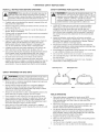
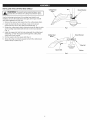
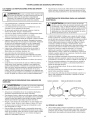
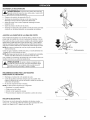
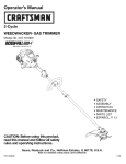
Prevent disconnection of the powerhead from the extension
cord during operation by using a plug-receptacle retaining strap,
connector, or by making a knot (Fig. A).
Avoid dangerous environments. Never operate your unit in damp
or wet conditions. Moisture is a shock hazard.
Do not use the unit in the rain. Do not use in or around water.
Do not handle the plug or unit with wet hands or standing on
any wet surfaces.
Do not leave the unit plugged in when not in use, changing
attachments or while being serviced.
Clear the area of children, bystanders and pets; keep them
outside a 50-foot (15 m) radius, at a minimum. Even then, they are
still at risk from thrown objects. Encourage bystanders to wear
eye protection. If you are approached, stop the unit immediately.
Extension
Cord
Unit Power Cord
SAFETY WARNINGS FOR GAS UNITS
can explode if ignited.
the following
WARNING:
GasolineTake
is highly
flammableprecautions:
and its vapors
•
]
Store fuel only in containers specifically designed and approved
for the storage of such materials.
Always stop the engine and allow it to cool before filling the
tank. Never remove the fuel tank cap or add fuel when the
engine is hot. Always loosen the fuel tank cap slowly to relieve
any pressure in the tank before fueling.
Always mix and add fuel in a clean, well-ventilated outdoor area
where there are no sparks or flames. DO NOT smoke.
Never operate the unit without the fuel cap securely in place.
Avoid creating a source of ignition for spilled fuel. Wipe up any
spilled fuel from the unit immediately, before starting the unit.
Move the unit at least 30 ft. (9.1 m) from the fueling source and
site before starting the engine. DO NOT smoke.
Never start or run the unit inside a closed room or building.
Breathing exhaust fumes can kill. Operate this unit only in a well
ventilated outdoor area.
Fig. A
WHILE OPERATING
Wear safety glasses or goggles that meet current ANSI
standards and are marked as such. Wear ear/hearing protection
when operating this unit. Wear a face or dust mask if the
operation is dusty.
Wear heavy long pants, boots, gloves and a long sleeve shirt. Do
not wear loose clothing, jewelry, short pants, sandals or go
barefoot. Secure hair above shoulder level.
The trimmer attachment shield must always be in place while
operating the unit. Do not operate unit without both trimming
lines extended, and the proper line installed. Do not extend the
trimming line beyond the length of the shield.
Adjust the handle to provide the best grip.
Make sure the attachment is not in contact with anything before
starting the unit.
Use the unit only in daylight or good artificial light.
Use the right tool. Only use this tool for its intended purpose.
3
,i,
Always hold the unit with both hands when operating. Keep a
firm grip on both handles or grips.
Do not overreach. Always keep proper footing and balance. Take
extra care when working on steep slopes or inclines.
Keep hands, face, and feet away from all moving parts. Do not
touch or try to stop moving parts.
Do not operate the unit faster than the speed needed to do the job.
Do not run the unit at high speed when not in use.
Use extreme caution when reversing or pulling the unit towards you.
DO NOT force the unit. It will do a better, safer job when used at
the intended rate.
OTHER SAFETY WARNINGS
All service, other than the maintenance procedures described in
this manual, should be performed by a Sears or other qualified
service dealer.
Before inspecting, servicing, cleaning, storing, transporting
replacing any parts on the unit:
1. Stop the unit.
2. Make sure all moving parts have stopped.
3. Allow the unit to cool.
4. For gas-powered units, disconnect the spark plug wire. For
electric-powered units, disconnect the unit from the power source.
Never store the unit with fuel in the tank, inside a building where
fumes may reach an open flame (pilot lights, etc.) or sparks
(switches, electrical motors, etc.).
Be sure to secure the unit while transporting.
Store the unit in a dry place, secured or at a height to prevent
unauthorized use or damage. Keep out of the reach of children.
Always stop the unit when operation is delayed or when walking
from one location to another.
If you strike or become entangled with a foreign object, stop the
unit immediately and check for damage. Do not operate before
repairing damage. Do not operate the unit with loose or
damaged parts.
Use only original equipment manufacturer (OEM) replacement
parts and accessories for this unit, as listed in the Parts List
section of this manual. Use of any other parts or accessories
could lead to serious injury to the user, or damage to the unit,
and void the warranty.
If the unit starts to vibrate abnormally, stop the unit immediately.
Inspect the unit for the cause of the vibration. Vibration is
generally an indicator of trouble.
Keep the unit clean of vegetation and other materials that may
become lodged between the cutting head and shield.
To reduce fire hazard, replace a faulty muffler and spark arrestor.
Keep the engine and muffler free from grass, leaves, excessive
grease or carbon build up.
,,,SAFETY
or
Never douse or squirt the unit with water or any other liquid.
Keep handles dry, clean and free from debris. Clean after each
use, see Cleaning and Storage instructions.
Keep these instructions. Refer to them often and use them to
instruct other users. If you loan this unit to others, also loan
them these instructions.
SAVE THESE INSTRUCTIONS
& INTERNATIONAL
SYMBOLS
,,
This operator's manual describes safety and international symbols and pictographs that may appear on this product. Read the operator's
manual for complete safety, assembly, operating and maintenance and repair information.
SYMBOL
_L
"_
"l_
MEANING
' Indicates danger warning or caution. May be used in
, SAFETY ALERT SYMBOL
conjunction with other symbols or pictographs.
WARNING:
Read the operator's manual(s) and
o follow
READ all
OPERATOR'S
warnings andMANUAL
safety instructions. Failure to
do so can result in serious injury to the operator
. and/or bystanders.
4t
"-_1,I
I.
WARNING: Thrown objects and loud noise can
_ o WEAR EYE AND HEARING PROTECTION
causesevereeye
njuryandhearingloss
Weareye
protection meeting current ANSI standards and ear
protection when operating this unit. Use a full face
shield when needed.
SYMBOL
S_
S,A
A
-€
MEANING
,THROWN OBJECTS AND ROTATING CUTTER CAN
CAUSE SEVERE INJURY
WARNING:
Small Objects Can be propelled at high
speed, caus!ng injury, Keep away from _he r0tating rOtOr.
,KEEP
BYSTANDERS AWAY
WARNING:
Keep
a,bySta"ders;
eSpeda,y
Ch,dren
and petsl at least 50 feet (15 m)from the operating area;
, SHARP BLADE
WARNING:
sharp b!ade on tdmmer attachment
shield. To prevent Serious injury, donot touch the line
cutting blade:
CRAFTSMAN
TWO
YEAR FULL
WARRANTY
FOR TWO YEARS from the date of purchase, this product is warranted against any defects in material or workmanship. A defective product
will be replaced free of charge.
For warranty details to obtain free replacement, visit the web site: www.craftsman.com
This warranty does not cover the cutting line, which is an expendable part that can wear out from normal use within the warranty period.
This warranty is void if this product is ever used while providing commercial services or if rented to another person.
This warranty gives you specific legal rights, and you may also have other rights which vary from state to state.
Sears Brands Management
Corporation,
Hoffman Estates, IL 60179
5
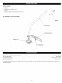
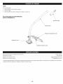
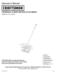
APPLiCATiONS
Asatrimmer:
• Cutting
grassandlightweeds.
Edging
Decorative
trimming
around
trees,fences,
etc.
NO ASSEMBLY TOOLS REQUIRED
Hanger
Shaft Housing
Cutting
Line Cutting
Approximate Unit Weight (attachment only) ....................................................................
Trimmer Mechanism .......................................................................................
Trimming Line Diameter ...........................................................................
Cutting Path Diameter ..................................................................................
* All specifications are based on the latest product information
time without notice.
Head Shield
Blade
2 Ibs. (0.9 kg)
Bump Head
0.095 inches (2.41 mm)
17 in. (43.18 cm)
available at the time of printing. We reserve the right to make changes at any
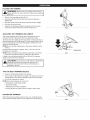
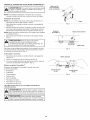
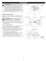
iNSTALLiNG
THE CUTTING
HEAD
SHIELD
Cutting Head
Shield
_
operate the unitTowithout
cuttingpersonal
head shield
place.
WARNING:
preventthe
serious
injury,innever
Slot
/
]
Use the following instructions if the cutting head shield is not
installed. Use only the instructions that apply to the type of shaft
and shield equipped with this unit.
1. Remove the wing nut and washer from the cutting head shield.
Insert the short tab (the one without a hole) on the mount
bracket into the slot on the cutting head shield (Fig. 1).
3. Rotate the cutting head shield counterclockwise to align the hole
on the cutting head shield with the hole on the mount bracket
(Fig. 1).
4. Insert the square bolt into the hole underneath the cutting head
shield (Fig. 2). Push the square bolt through the cutting head
shield and mount bracket.
Mount Bracket
2.
5. Put the washer onto the square bolt (Fig. 2).
6. Screw the wing nut onto the square bolt until the cutting head
shield is firmly in place (Fig. 2).
Fig. 1
Mount
Cutting Head
Shield
Bracket
Wing Nut
Square Bolt
Washer
Fig. 2
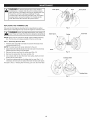
OPERATING THE CONVERTIBLE
TM
COUPLER SYSTEM
90° Edging
Hole
|
[__J
damage to the unit, shut the unit off before removing or
WARNING:
To avoid serious personal injury and
installing an attachment.
NOTE: To make installing or removing the attachment
the unit on the ground or on a work bench.
installing
1
_
Only)
|
easier, place
the Attachment
NOTE: Remove the protective cap and gray spacer from the upper
and lower shafts prior to assembling the attachment.
1. Turn the knob counterclockwise to loosen (Fig. 3).
2. While firmly holding the attachment, push it straight into the
Convertible TM coupler until the release button snaps firmly into
the primary hole (Fig. 5).
NOTE: Aligning the release button with the guide recess will help
installation (Fig. 4).
3.
(Trimmer
Knob
Fig. 3
Convertible
Coupler
TM
Release Button
Turn the knob clockwise to tighten (Fig. 3).
release button is fully snapped into the primary hole (Fig. 5),
CAUTION:
Before
operating
this unit,
be sure that the
1
and
that the knob
(Fig.
3) is securely
tightened.
For decorative edging with the line head trimmer attachment, lock
the release button of the attachment into the 90 ° hole (Fig. 3).
Removing
Guide Recess
the Attachment
Fig. 4
1. Turn the knob counterclockwise to loosen (Fig. 3).
2. Press and hold the release button (Fig. 4).
3. While firmly holding the upper shaft housing, pull the attachment
straight out of the Convertible TM coupler (Fig. 5).
The Convertible
The Convertible
attachments.
•
TM
TM
Primary Hole
Coupler System
coupler system enables the use of these optional
Edger*
Cultivator
Turbo Blower
Brushcutter*
Pole Saw
Upper Shaft
Housing
Hedge Trimmer
Straight-shaft trimmer
Curved-shaft trimmer
*DO NOT use this attachment
_
Lower Shaft
Housing
Fig. 5
with an electric-powered
unit.
read and understand the manual that came with the
ARNING: Follow
Beforeallyou
begin
using anycontained
attachment,
attachment.
safety
information
within.
the primary hole only. Using the wrong hole could lead to
I_!CAUTJON:Theseattachmentsaretobesnappedinto
personal injury or damage to the unit.
J
!
HOLDING
THE TRIMMER
body protection to reduce the risk of injury when operating|
WARNING:
Always wear eye, hearing, hand, foot and
I
this unit.
J
•
Stand in the operating position (Fig. 6).
Hold the shaft grip with the right hand. Keep the right arm
slightly bent.
Hold the handle with the left hand. Keep the left arm straight.
Hold the unit at waist level.
Keep the cutting head parallel to the ground so that it easily
contacts the grass without the need for bending over.
ADJUSTING THE TRiMMiNG
Fig. 6
LiNE LENGTH
This unit is equipped with a Bump Head. Trimming line can be
released from the cutting head without stopping the engine.
To release more line, lightly tap the bump knob on the ground (Fig. 7)
while operating the unit at high speed. For best results, tap the bump
knob on bare ground or hard soil. Attempting to release line in tall
grass may stall the engine.
NOTE: Do not rest the cutting head on the ground while the unit is
running.
Each time the bump knob is tapped, about 1 inch (25.4 mm) of
trimming line is released.
NOTE: Always keep the trimming line fully extended. Line release
becomes more difficult when the cutting line gets shorter.
A blade in the cutting head shield will cut the line to the proper
length if any excess line is released.
- Bump Knob
Fig. 7
CAUTION:
Do not remove or alter the line cutting blade
assembly. Excessive line length will make the unit
overheat. This may lead to serious personal injury or
damage to the unit.
TiPS FOR BEST TRiMMiNG
=
RESULTS
Keep the cutting head parallel to the ground.
Cut from left to right whenever possible. This improves the unit's
cutting efficiency and throws clippings away from the operator.
Do not trim wet grass or weeds.
NOTE: Some line breakage will occur from:
Entanglement with foreign matter
Normal line fatigue
Attempting to cut thick vegetation
Forcing the line into objects such as walls or fence posts
\
30 °
DECORATIVE
TRiMMiNG
When trimming around trees, posts, fences, etc., rotate the whole
unit so that the cutting head is at a 30 ° angle to the ground (Fig. 8).
Fig. 8
9
WARNING:
To prevent serious injury, never perform
maintenance or repairs while the unit is running. Always
allow the unit to cool before servicing or repairing the unit.
Prevent the unit from starting accidentally. For gaspowered units, disconnect the spark plug wire. For batterypowered units, remove the battery. For corded electric
units, disconnect the unit from the power source.
REPLACING
THE TRiMMiNG
Outer Spool
Bolt
Bump Knob
LiNE
Only use the trimming line described in the Specifications section.
Other types of trimming line may cause the engine to overheat or fail.
L_J
rope.
These canNever
breakuse
off metal-reinforced
and become dangerous
ARNING:
line, wire,projectiles.
chain or
J
Outer Spool
Spring
inner Reel
NOTE: Always use the correct line length when installing trimming
line. The line may not release properly if the line is too long.
Part 1 - Removing
the inner Reel
1.
Hold the outer spool with one hand and unscrew the bump knob
counterclockwise (Fig. 9).
NOTE: The outer spool will remain attached to the unit.
2. Inspect the bolt inside the bump knob to make sure it moves freely.
Replace the bump knob if it is damaged.
3. Remove the inner reel from the outer spool (Fig. 10).
4. Remove the spring from the inner reel (Fig. 10).
5. Use a clean cloth to clean the inner reel, spring, shaft and inner
surface of the outer spool.
Fig. 10
indexing Teeth
6.
Check the indexing teeth and holding slots for wear (Fig. 11). If
necessary, remove burrs or replace the inner reel and outer spool.
Proceed to Part 2 - Winding New Trimming Line onto the inner Reel.
Holding
Fig. 11
10
Slots
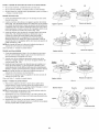
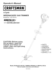
Part 2 - Winding New Trimming Line onto the inner Reel
=
•
A
B
If using single line, refer to Winding Single Line.
If using split line, refer to Winding Split Line.
If using a prewound inner reel, proceed to Part 3 - Installing the
Inner Reel.
Winding
Single Line
1. Cut two 8-foot (2.4 m) lengths of new single trimming line.
2. Insert the end of one line into the top hole in the inner reel (Fig.
12A). Wind the line tightly in the direction shown on the bottom
of the inner reel until about 6 inches (150 mm) of line remains.
Keep the line above the split wall. Insert the 6-inch section into
the nearest .095 holding slot (Fig. 12B).
3. Insert the end of the other line into the bottom hole in the inner reel
(Fig. 13A). Wind the line tightly in the direction shown on the bottom
of the inner reel until about 3 to 9 inches (75 to 225 mm) of line
remains. Keep the line below the split wall. Insert the 3 to 9-inch
section into the opposite .095 holding slot (Fig. 13B).
NOTE: Failure to wind the line in the direction indicated will cause
the cutting head to operate incorrectly.
Proceed to Part 3 - Installing the Inner Reel.
Winding
Holding Slot
Top Hole
Fig. 12
A
B
Wall
Split Line
1. Cut one 6-foot (1.8 m) length of new split line trimming line. Split
each end about 6 inches (150 mm).
2. Using one split end, insert one line into the top hole and the
other line into the bottom hole in the inner reel (Fig. 14A).
3. Wind the line tightly in the direction shown on the bottom of the
inner reel. The split wall will automatically divide the line. Wind
the line until it is completely divided and about 6 inches (150
mm) of line remains.
NOTE: Failure to wind the line in the direction indicated will cause
the cutting head to operate incorrectly.
4. Insert the two 6-inch sections into the two .095 holding slots
(Fig. 14B).
Proceed to Part 3 - Installing the Inner Reel.
Part 3 - installing
Bottom
Holding
Hole
Slot
Fig. 13
B
A
Top Hole
_
_
Split
Wall
the inner Reel
1.
Pass the two line ends through the eyelets in the outer spool.
Place the spring inside the inner reel. Insert the inner reel into
the outer spool. Push the inner reel and outer spool together
(Fig. 15).
NOTE: The spring must be assembled on the inner reel before
reassembling the cutting head.
2. While holding the inner reel and outer spool together, firmly pull
the two line ends to release them from the holding slots.
Bottom
Hole
Holding
Slots
Fig. 14
Outer Spool
3. While holding the inner reel and outer spool together, screw the
bump knob on clockwise. Tighten the bump knob securely.
Spring
inner Reel
Bump Knob
Fig. 15
11
CLEANING
STORAGE
•
_
the unit and allow it to cool before cleaning or maintaining
theARNING:
unit.
To avoid serious personal injury, always stop
J
Use a small brush to clean the outside of the unit. Do not use strong
detergents. Household cleaners that contain aromatic oils such as
pine and lemon, and solvents such as kerosene, can damage plastic.
Wipe off any moisture with a soft cloth.
Never store a fueled unit where fumes may reach an open flame
or spark.
Allow the engine to cool before storing.
Lock up the unit to prevent unauthorized use or damage.
Store the unit in a dry, well-ventilated area.
Store the unit out of the reach of children.
Short-term
Storage for Gas-Powered
Units (1-2 weeks)
1. Store the unit in a horizontal position. If this is not possible, store
the unit vertically with the engine at the top.
Long-term Storage
1. Thoroughly clean the unit and inspect it for any loose or
damaged parts. Repair or replace damaged parts and tighten
loose screws, nuts or bolts.
Long-term Storage for Gas-Powered
Units
1. Remove the fuel cap, tip the unit and drain the fuel into an
approved container.
2. Start the engine and allow it to run until it stalls. This ensures
that all fuel has been drained from the carburetor.
3. Allow the engine to cool. Remove the spark plug and put 5 drops
of any high quality motor oil into the cylinder. Pull the starter rope
slowly to distribute the oil. Reinstall the spark plug.
Preparing a Gas-Powered
Unit for Use after Long=term
Storage
1. Remove the spark plug and drain all of the oil from the cylinder.
NOTE: Do not use fuel that has been stored for more than 30 days.
Dispose of old fuel according to federal, state and local regulations.
12
PROBLEM
SOLUTION
Thecuttingheadisboundwithgrass
Clean
thecuttinghead
Theinnerreelisboundup
Rewind
theline
Thelineiswelded
Openthecuttingheadandremove
thewelded
section
iiiiiiiiiiii_i/i/liiii_iiiiil_iiiiiiiiiiiiiiiiiiiiiiiiiiiiiiiiiiiiiiiii
_
_iiiiiiiiiiii_ii[iiiiiii_
Notenough
lineisextended
Stop the unit, push the bump knob and pull the line until 4 inches
(102 mm) is outside of the cutting head
There
isoil,cleaner
orlubricant
inthecuttinghead
Clean and thoroughly dry the cutting head
HELP?
_ J ,,,s,
"_
,"_Lt t:
° Find this
L, ,s I,,.......................
,,,...........
and al your other
= Get answers
from our team
"
........
product
manuals
of home
experts.
13
_ .......!! ...............
online.
"........
Congratulations on making a smart purchase. Your new Craftsman@ product is designed and manufactured for years of dependable
operation. But like all products, it may require repair from time to time. That's when having a Repair Protection Agreement can save you
money and aggravation.
Here's what the Repair Protection Agreement*
includes:
[]
Expert service
[]
[]
[]
Unlimited service and no charge for parts and labor on all covered repairs
Product replacement up to $1500 if your covered product can't be fixed
Discount of 25% from regular price of service and related installed parts not covered by the agreement; also, 25% off regular price of
preventive maintenance check
Fast help by phone - we call it Rapid Resolution - phone support from a Sears representative. Think of us as a "talking owner's manual."
[]
by our 10,000 professional repair specialists
Once you purchase the Repair Protection Agreement, a simple phone call is all that it takes for you to schedule service. You can call anytime
day or night, or schedule a service appointment online.
The Repair Protection Agreement is a risk-free purchase. If you cancel for any reason during the product warranty period, we will provide a
full refund. Or, a prorated refund anytime after the product warranty period expires. Purchase your Repair Protection Agreement today!
Some limitations and exclusions apply. For prices and additional information in the U.S.A. call 1-800-827-6655.
*Coverage in Canada varies on some items. For full details call Sears Canada at 1-800-361-6665.
Sears installation Service
For Sears professional instaflation of home appliances,
Canada call 1-800-4-MY-HOME.
garage door openers, water heaters, and other major home items, in the U.S.A. or
14
Manual
del Operador
M
ACCESORIO
UNIVERSAL PARA RECORTADOR
DE EJE CURVO
Modelo No. 316.792520
o SEGURIDAD
PRECAUCION: Antes de utilizar, este
producto lea este manual y siga todas
las reglas de seguridad
e instrucciones
de operaci6n.
Sears Brands Management
Corporation,
Visite nuestro
769-07353 P00
o ENSAMBLAJE
o OPERACION
o LISTA DE PIEZAS
Hoffman
Estates, IL 60179 U.S.A.
sitio web: www.craftsrnan.corn
01/12
TABLA DE CONTENIDO
Seguridad ...........................................
Garantia .............................................
Conozca su unidad ....................................
16
19
20
Especificaciones
......................................
Ensamblaje ..........................................
Operaci6n ...........................................
Mantenimiento ........................................
20
21
23
24
Limpieza y almacenamiento
.............................
Localizaci6n y soluci6n de problemas .....................
26
27
Convenio de protecci6n de reparaci6n .....................
28
Lista de piezas .......................................
31
NQmeros de servicio .........................
Contraportada
Toda la informaci6n, las ilustraciones y especificaciones que contiene
este manual se basan en la informaci6n mas reciente del producto,
existente en el momento de la impresi6n. Nos reservamos el derecho
de hacer cambios en cualquier momento, sin previo aviso.
Lea el manuaa del operador y siga todas las advertencias e
instrucciones de seguridad. No hacerlo puede ocasionar
lesiones graves al operador y/o a las personas presentes.
El prop6sito de los simbolos de seguridad es Ilamar la atenci6n
sobre posibles peligros. Los simbolos de seguridad y sus
explicaciones merecen toda su atenci6n y comprensi6n. Las
advertencias de seguridad no eliminan de por si ningQn peligro.
Las instrucciones o advertencias que dan no sustituyen las
medidas adecuadas de prevenci6n de accidentes.
SJMBOLO
SlGNIFICADO
PEUGRO:
Indica un peligro EXTREMO.
El no obedecer una sehal de seguridad de PEUGRO
TRAERA COMO CONSECUENClA que usted u otras
personas puedan sufrir lesiones graves o la muerte.
ADVERTENCIA:
Indica un peligro GRAVE.
El no obedecer una sehal de ADVERTENClA de seguridad
PUEDE conducir a que usted u otras personas sufran
graves lesiones.
PRECAUCl0N:
Jndica un peligro MODERADO.
El no obedecer una sehal de PRECAUClON de seguridad
PUEDE conducir a dahos a la propiedad o a que usted u
otras personas se lesionen.
NOTA: Indica informaci6n o instrucciones de vital importancia
la operaci6n o el mantenimiento del equipo.
para
16
• INSTRUCCIONES
LEA TODAS LAS INSTRUCCIONES
LA UNIDAD
_
•
DE SEGURIDAD
ANTES DE OPERAR
ADVERTENCIAS
ELECTRICAS
PARA LAS UNIDADES
Para reducir el riesgo de descarga
electrica, use s61o cables de extensi6n aprobados para uso
en exteriores, como un cable de extensi6n con cable tipo
SW-A, SOW-A, STW-A, STOW-A, SJW-A, SJOW-A, SJTWW o SJTOW-A. Puede adquirir cables de extensi6n en su
distribuidor local. Use s61o cables de extensi6n de camisa
cilindrica aprobados para su uso al exterior.
No opere esta unidad siesta cansado, enfermo o bajo los
efectos del alcohol, drogas o medicamentos.
Los ni_os no deben operar la unidad. Los adolescentes deben
estar acompa_ados y supervisados pot un adulto.
Todos los accesorios de protecci6n y seguridad deben estar
instalados adecuadamente antes de comenzar a operar la unidad.
Inspeccione la unidad antes de utilizarla. Reemplace las piezas
da_adas. Verifique que no haya fugas de combustible. AsegOrese
de que todos los sujetadores esten en su sitio y asegurados.
Cambie las piezas rajadas, melladas o da_adas de cualquier
forma. No opere la unidad si hay piezas flojas o da_adas.
Inspeccione cuidadosamente el Area antes de encender la
unidad. Elimine todos los escombros y los objetos duros o
filosos tales como cristales, alambres, etc.
Use solo la linea de corte indicada en la secci6n
Especificaciones. No use nunca la linea reforzada con metal,
alambre, cadena o soga. Los mismos pueden desprenderse y
convertirse en un proyectil peligroso.
JUEGOS DE CABLES: Verifique que su juego de cable este en
buenas condiciones. Cuando use un juego de cables, verifique
que el cable que usa es Io suficientemente grueso para conducir
la corriente que consumira la unidad. Un juego de cables de
menor calibre puede causar una caida de voltaje en la linea y
ocasionar la perdida de energia y recalentamiento. Vea el
manual del operador de la unidad que le data electricidad a este
accesorio para saber la medida recomendada para el cable.
Inspeccione todos los cables de extensi6n y la conexi6n
electrica de la unidad con frecuencia. Observe en detalle si
existe deterioro, cortes o grietas en el aislamiento. Inspeccione
tambien si existen da_os en las conexiones. Cambie los cables
si encuentra algOn defecto o da_o.
Evite que el cabezal motorizado se desconecte del cable de
extensi6n durante la operaci6n usando una correa de sujeci6n en
el receptaculo o enchufe, un conector, o hagale un nudo (Fig. A).
Evite los ambientes peligrosos. No opere nunca su unidad en
ambientes hOmedos ni mojados. La humedad representa un
peligro de descarga electrica.
No use la unidad bajo la Iluvia. No la use dentro del agua ni
alrededor de ella.
Tenga en cuenta el riesgo de lesiones a la cabeza, las manos y
los pies.
Limpie el Area a recortar antes de cada uso. Retire las piedras,
vidrios rotos, clavos, alambres, cadenas y otros objetos que
podrian salir despedidos o enredarse en el accesorio de corte.
Aleje a los ni_os, personas presentes y animales domesticos del
Area; mantengalos fuera de un radio de 50 pies (15 m) como
minimo. AOn asi es posible que se arriesguen a ser golpeados por
los objetos lanzados. Sugiera a los presentes usar protecci6n para
los ojos. Si alguien se le acerca, pare la unidad inmediatamente.
PARA UNIDADES
DE SEGURIDAD
ADVERTENCIA:
Lea cuidadosamente y entienda el manual del operador de la
unidad que impulsa a este acople.
Lea detenidamente las instrucciones. Familiaricese con los
controles y el uso adecuado de la unidad.
DE SEGURIDAD
•
No arranque ni use nunca la unidad dentro de una habitaci6n o
edificio cerrados. Inhalar los gases de escape puede ser fatal.
Opere esta unidad solamente en un Area exterior bien ventilada.
las normas de seguridad. Lea estas instrucciones antes de
operar la unidad a fin de garantizar la seguridad del
I
operador
y de cualquier
otra la
persona
Guardetodas I
DVERTENCIA:
AI usar
unidad presente.
deben seguirse
estas instrucciones para poder usarlas mas adelante,
j
ADVERTENCIAS
GASOUNA
IMPORTANTES
No toque el enchufe ni la unidad con las manos mojadas ni
parado sobre superficies mojadas.
Do not leave the unNo deje la unidad enchufada cuando no se
utilice, este cambiando los accesorios o mientras se le esta
dando mantenimiento.
DE
Cable de extensi6n
Cable de alimentaci6n
de la unidad
y, de prenderse, sus vapores pueden hacer expos 6n.
|
ADVERTENCIA:
La gasolina es sumamente inflamable
Tome las siguientes precauciones:
J
Almacene el combustible solo en los recipientes dise_ados y
aprobados especificamente para estos materiales.
Pare siempre el motor y deje que se enfrie antes de Ilenar el tanque.
Nunca quite la tapa del tanque de combustible ni eche combustible
cuando el motor este caliente. Antes de Ilenar el tanque, siempre
afloje la tapa lentamente para disipar la presi6n del mismo.
Mezcle o eche siempre el combustible en un Area exterior bien
ventilada y limpia, donde no haya chispas ni llamas. NO fume.
No opere nunca la unidad si la tapa del combustible no esta
bien asegurada en su lugar.
Evite el peligro de incendio debido a combustible derramado.
Limpie de inmediato todo combustible derramado de la unidad
antes de encenderla. Antes de arrancar el motor, aleje la unidad
a una distancia de 30 pies (9.1 m) como minimo del lugar de
abasto de combustible. NO fume.
Fig. A
AL OPERAR LA UNIDAD
Lleve puestas gafas o lentes de seguridad que cumplan las
normas actuales ANSI y esten marcados como tales. Use siempre
protecci6n para los oidos al operar esta unidad. Si la operaci6n
levanta polvo, Ileve puesta una mascara facial o contra el polvo.
17
• Usepantalones
largos
y gruesos,
botas,guantes
y camisa
de
mangas
largas.
Nouseropaholgada,
alhajas,
pantalones
cortos,
sandalias
niandedescalzo.
Asegure
sucabello
por
encima
delniveldeloshombros.
Elprotector
delaccesorio
delarecortadora
debeestarsiempre
ensusitiomientras
seoperelaunidad.
Nooperelaunidad
sinlas
doslineas
decorteextendidas
ylalineacorrecta
instalada.
No
extienda
lalineadecortemasaliadelaIongitud
delprotector.
Ajusteelmangoparafacilitar
elmejoragarre.
Antesdearrancar
launidad,
asegQrese
dequeelaccesorio
no
hagacontacto
conningQn
objeto.
Uselaunidad
Qnicamente
alaluzdeldiaoconbuena
luzartificial.
Uselaherramienta
correcta.
Useestaherramienta
solamente
conelprop6sito
previsto.
Sostenga
siempre
launidad
conambas
manos
aloperarla.
Agarre
firmemente
ambos
mangos
o empufiaduras.
Nointente
alcanzar
demasiado
lejos.Mantenga
siempre
una
posici6n
y equilibrio
adecuados.
Tenga
mucho
cuidado
cuando
estetrabajando
enpendientes
pronunciadas
o inclinadas.
Mantenga
lasmanos,
lacaray lospieslejosdetodaslaspartes
m6viles.
Notoqueotratededetener
laspiezas
m6viles.
Nooperelaunidad
a unavelocidad
mayorquelanecesaria
para
recortar
bordes.
Nooperelaunidad
aaltavelocidad
cuando
no
esterecortando
bordes.
Tenga
mucho
cuidado
cuando
invierta
o mueva
launidad
hacia
usted.
NOfuerce
elequipo.
Elmismo
trabajara
mejoryconmayor
seguridad
siIoutilizaalavelocidad
paralaquehasidodisefiado.
Paresiempre
launidad
cuando
posponga
eltrabajoomientras
camine
entrediferentes
zonas
decorte.
Sigolpea
oseenreda
conunobjetoextrafio,
paredeinmediato
launidad
y verifique
sihayalgQn
dafio.Nopongaafuncionar
el
equipo
sinreparar
eldafio.Nooperelaunidad
sihaypiezas
flojaso dafiadas.
Utilicesolamente
laspiezas
derepuesto
y accesorios
del
fabricante
original
queselistanenlasecci6n
Listadepiezas
de
estemanual.
Elusodecualquier
piezao accesorio
no
autorizado
podria
causar
lesiones
graves
alusuario
o dafiosa la
unidad
y anularlagarantia.
Silaunidad
comienza
avibraranormalmente,
detengala
de
inmediato.
Inspeccione
launidad
paraencontrar
lacausadela
vibraci6n.
Generalmente,
lavibraci6n
esunindicador
de
problemas.
• SiMBOLOS
Mantenga
launidad
limpiadevegetaci6n
y otrosmateriales
que
puedan
trabarse
entreelaccesorio
decortey elprotector.
Paraevitarelpeligro
deincendio,
reemplace
elsilenciador
y
parachispas
defectuosos.
Mantenga
elmotory elsilenciador
sin
hierbas,
hojas,grasaexcesiva
ysinacumulaci6n
decarb6n.
OTRAS ADVERTENCIAS
DE SEGURIDAD
Todos los servicios, que no sean los procedimientos de
mantenimiento descritos en este manual, deberan realizarse por
un centro de Sears u otto centro de servicio autorizado.
Antes de inspeccionar, dar mantenimiento, limpiar, guardar,
transportar o reemplazar cualquier pieza de la unidad:
1. Detenga la unidad.
2. AsegQrese de que todas las piezas m6viles esten detenidas.
3. Espere a que la unidad se enfrie.
4. Para las unidades que funcionan con gasolina, desconecte el
cable de la bujia. Para las unidades que funcionan con
electricidad, desconecte la unidad de la alimentaci6n
electrica.
No guarde nunca la unidad con combustible en el tanque ni
dentro de una edificaci6n en la que los gases puedan ponerse
en contacto con una llama expuesta (luces piloto, etc.) o
chispas (interruptores, motores electricos, etc.).
Cerci6rese de asegurar bien la unidad al transportarla.
Guarde la unidad en un lugar seco, bajo Ilave o en alto, a fin de
evitar su uso no autorizado o dafio. Mantengala fuera del
alcance de los nifios.
No moje ni rocie la unidad con agua ni con ningQn otro
Mantenga los mangos secos, limpios y sin suciedades.
unidad despues de cada uso, consulte las instrucciones
Limpieza y almacenamiento.
Guarde estas instrucciones. ConsQItelas con frecuencia
utilicelas para instruir a otros usuarios. Si le presta esta
alguien, prestele tambien estas instrucciones.
GUARDE
INTERNACIONALES
liquido.
Limpie la
de
y
unidad a
ESTAS INSTRUCCIONES
Y DE SEGURIDAD
•
Este manual del operador describe simbolos y pictografias internacionales y de seguridad que posiblemente aparezcan en este producto.
Lea el manual del operador para informarse bien sobre la seguridad, ensamblaje, operaci6n, mantenimiento y reparaci6n.
SJMBOLO
:_
SIGNIFICADO
o SjMBOLO DEALERTA
_
SJMBOLO
DE SEGURIDAD
preoauci6n: Pue de
utilizarse ]unto a otros simbolos o pictografias.
_
ADVERTENCIA:
/
ei e iOSmanUaiesdei
LEA EL MANUAL
DEL OPERADOR
operadQr
Ys gatodas
a vertencias
e nstwccioneS
*'_7,,t,._4L' LOS OBJETOS QUE SALEN DESPEDIDOS Y LA
_/-_'_
CUCHILLA
GIRATORIA
PUEDEN OCASIONAR
LESION ES G
RAVES
J
Amf
J_'_
ADVERTENCIA:
Los objetos pequefios pueden
ser anzados a gran velocidad y ocasionar lesiones.
Mant6ngase alejado del rotor cuando est6 girando.
de segurida& No hacedo puede 0casionar lesiones
graves a! operador y/o a !as personas presentes;
I
q
SIGNIFICADO
ADVERTENCIA:
Mantenga a todos los presentes,
' MANTENGA
LOS PRESENTES
especialmente ALEJADOS
a los nifios A
y animales
dom6sticos, a
una distancia de al menos 50 pies (15 m).
usePRoTEccl6N
PARA
LOSOJOS¥OiDOS
I
I
ADVERTENC Los
A:objei0s
ianzad0S
Y ruid0
fuerte pueden ocasionar lesiones graves a los ojos y
p6rdida de la audici6n: A! 0perar esta unidad, use
protecci6n para loS 0J0s que cumpla con la norma s
ANS! y protecci6n para !os 0ides; De ser necesario,
use un protector facia! comp!eto;
ADVERTENCIA:
.._'
18
Cuchilla afilada en el protector
del
accesorioAFILADA
de corte. A fin de evitar les ones graves
CUCHILLA
no toque nunca la cuchilla de corte de la linea
GARANTiA
TOTAL
POR DOS ANOS
CRAFTSMAN
Este producto se garantiza POR DOS ANOS a partir de la fecha de compra, contra cualquier defecto de materiales o mano de obra. Un
producto defectuoso sera sustituido sin cargo alguno.
Para conocer los detalles de la cobertura a fin de obtener el reemplazo gratuito, visite el sitio web: www.craftsman.com
Esta garantia no cubre la I{nea de corte, que es una pieza consumible que se desgasta debido al uso normal dentro del per{odo de garant{a.
Esta garantia se anula si el producto en alg_n momento se utiliza para prestar servicios comerciales o se alquila a otra persona.
Esta garantia le confiere a usted derechos legales especificos y usted puede tener, ademas, otros derechos que difieren de un estado a otro.
Sears Brands Management
Corporation,
Hoffman Estates, IL 60179
19
usos
Como recortadora:
•
Cortar cesped y malas hierbas escasas.
Orillar (bordear)
Hacer recortes decorativos alrededor de arboles, cercas, etc.
NO SE REQUIERE DE HERRAMIENTAS
PARA EL ENSAMBLAJE
Asa para coJgar
Cuerpo
deJ eje
Protector deJ cabezaJ de corte
CabezaJ de corte
CuchilJa
Peso aproximado de la unidad (s61o el accesorio) .............................................................
Mecanismo de corte .......................................................................................
Diametro de la linea de corte .....................................................................
Diametro de la senda de corte ......................................................................
de Ja Ifnea de corte
2 libras (0.9 kg)
Bump Head
0.095 pulgadas (2.41 mm)
17 pulgadas (43.18 cm)
* Todas las especificaciones se basan en la informaci6n del producto mas reciente disponible en el momento de la impresi6n. Nos reservamos
el derecho de hacer cambios en cualquier momento, sin previo aviso.
2O
INSTALACI()N DEL PROTECTOR DEL CABEZAL DE CORTE
Protector del
cabezal de corte
I_
graves, no opere nunca la unidad sin el protector del
_ADVERTENClA:
Para evitar lesiones personales
cabezal de corte colocado.
RanlLira
Soporte de
montaje
S
]
Si el protector del cabezal de corte no esta instalado, siga las
instrucciones a continuaci6n. Siga solamente las instrucciones que
correspondan al tipo de eje y protector con que esta equipada esta
unidad.
1. Quite la tuerca de mariposa y la arandela del protector del
cabezal de corte.
2.
3.
4.
5.
6.
Fig. 1
Inserte la lengQeta corta (la que no tiene orificio) del soporte de
montaje en la ranura del protector del cabezal de corte (Fig. 1).
Rote el protector del cabezal de corte en sentido contrario alas
agujas del reloj para alinear el orificio del protector del cabezal
de corte con el orificio en el soporte de montaje (Fig. 1).
Inserte el perno cuadrado en el orificio bajo el protector del
cabezal de corte (Fig. 2). Presione el perno cuadrado a traves
del protector del cabezal de corte y el soporte de montaje.
Coloque la arandela en el perno cuadrado (Fig. 2).
Enrosque la tuerca de mariposa en el perno cuadrado hasta que
el protector del cabezal de corte este firme en su lugar (Fig. 2).
Protector del
cabezal de corte
Soporte de montaje
I
Tuerca de
mariposa
Perno cuadrado
Arandela
Fig. 2
21
OPERAR EL SISTEMA DE ACOPLADOR
CONVERTIBLE
TM
Orificio de 90 °
para bordeadora
(solo recortadora)
y dados a la unidad, apague la unidad antes de quitar o
DVERTENClA:
Para evitar lesiones personales grave 1
instalar
cualquier accesorio.
[_J
NOTA: Para facilitar la instalaci6n o remoci6n de un accesorio,
coloque la unidad sobre el suelo o sobre un banco de trabajo.
Instalaci6n del accesorio
NOTA: Para ensamblar el accesorio, quite la tapa protectora y el
espaciador gris de los ejes superior e inferior.
1. Para aflojar, gire la perilla en sentido contrario alas agujas del
reloj (Fig. 3).
2. Mientras sostiene el accesorio con firmeza, empuje en linea recta
hacia dentro del acoplador Convertible TM hasta que el bot6n de
desconexi6n encaje firmemente en el agujero principal (Fig. 5).
NOTA: Alinear el bot6n de desconexi6n con el agujero guia facilitara
la instalaci6n (Fig. 4).
3. Para apretar, gire la perilla en el sentido de las agujas del reloj
(Fig. 3).
PeriUa
Fig. 3
Acoplador
Convertible
Bot6n de desconexibn
TM
cerci6rese de que el bot6n de liberaci6n este
completamente encajado en el orificio principal (Fig. 5) y
de bien
operar
esta unidad,
deRECAUCION:
que la perilla (Fig.Antes
3) este
apretada.
_
Agujero guia
Para hacer cortes (orillados) decorativos con el accesorio de corte
del cabezal de linea, trabe el bot6n de desconexi6n del accesorio
en el interior del orificio de 90 ° (Fig. 3).
Fig. 4
C6mo quitar el accesorio
1. Para aflojar, gire la perilla en sentido contrario alas agujas del
reloj (Fig. 3).
2. Oprima y sostenga el bot6n de desconexi6n (Fig. 4).
3. A la vez que sujeta firmemente la caja del eje superior, saque el
accesorio del acoplador Convertible TM (Fig. 5).
Sistema
acoplador
Convertible
Orificio
TM
El sistema del acoplador Convertible
accesorios opcionales.
• Bordeadora*
Cultivadora
TM
permite usar estos
Cuerpo superior
del eje
Sierra de pertiga
Recortadora de setos
Recortadora de eje recto
Recortadora de eje curvo
• NO utilice este accesorio con un equipo accionado
corriente el_ctrica.
Cuerpo inferior
del eje
Fig. 5
Turbosopladora
Desbrozadora*
_
principal
por
lea y familiaricese con el manual que viene con el mismo.
DVERTENClA:
Antes dedeutilizar
cualquier
accesorio,
Siga
todas las instrucciones
seguridad
que contengan.
j
solamente en el orificio principal. Usar un orificio incorrecto
podria ocasionar lesiones personales o dar_os a la unidad.
22
SOSTENER
LA
RECORTADORA
puesta protecci6n
para los ojos, oidos, pies y cuerpo a fin
ADVERTENCIA:
AI lesiones.
operar esta unidad, Ileve siempre
de reducir el riesgo de
•
J
Parese en la posici6n de operaci6n (Fig. 6).
Sostenga la empufiadura del eje con la mano derecha.
Mantenga el brazo derecho ligeramente flexionado.
Sujete el mango con la mano izquierda. Mantenga el brazo
izquierdo recto.
Sujete la unidad a la altura de la cintura.
Sostenga el cabezal de corte paralelo al suelo de modo que haga
contacto con la hierba facilmente, sin necesidad de inclinarse.
AJUSTAR LA LONGITUD
Fig. 6
DE LA LiNEA DE CORTE
Esta unidad esta equipada con un Bump Head. La linea de corte
puede salir del cabezal de corte sin necesidad de detener el motor.
Para soltar mas linea cuando opera la unidad a alta velocidad, golpee
ligeramente la perilla percusiva contra el suelo (Fig. 7). Para obtener
mejores resultados, golpee la perilla percusiva sobre terreno limpio o
suelo duro. Intentar soltar linea en cesped alto podria ahogar el motor.
NOTA: No apoye el cabezal de corte en el piso cuando la unidad
este funcionando.
Perilla percusiva
Cada vez que se golpea la perilla percusiva, se suelta alrededor de
1 pulgada (25.4 mm) de linea de corte.
NOTA: Mantenga siempre la linea de corte completamente extendida.
Resulta mas dificil soltar linea al acortarse la linea de corte.
Fig. 7
Una cuchilla en el protector del cabezal de corte cortara la linea a la
Iongitud correcta si se suelta demasiada linea.
PRECAUCION:
No quite ni altere el conjunto de la
cuchilla de corte de la linea. Una linea demasiado larga
hara que el motor se recaliente. Esto puede provocar
graves lesiones personales o dafiar la unidad.
RECOMENDAClONES
PARA LOS MEJORES
RESULTADOS
AL RECORTAR
Mantenga el cabezal de corte paralelo al suelo.
Corte de izquierda a derecha siempre que sea posible. Esto
mejora la eficiencia de corte de la unidad y arroja los recortes de
yerba lejos del operador.
\
No recorte cesped hQmedo ni maleza.
NOTA: La linea puede romperse por Io siguiente:
Enredarse con materia extrafia
Fatiga normal de la linea
Intentar cortar vegetaci6n espesa
Forzar la linea en objetos como paredes o postes de cercas
RECORTE DECORATIVO
Fig. 8
Para hacer un recorte decorativo alrededor de arboles, postes,
cercas, etc., gire toda la unidad de manera que el cabezal de corte
quede a un angulo de 30 ° respecto al suelo (Fig. 8).
23
ADVERTENClA:
Para evitar lesiones graves, no haga
nunca ningQn mantenimiento ni reparaci6n con la unidad
funcionando. Siempre deje que la unidad se enfrie antes de
darle mantenimiento o repararla. Evite que la unidad
arranque pot accidente. Para las unidades que funcionan
con gasolina, desconecte el cable de la bujia. Para las
unidades que funcionan con baterias, saque la bateria de la
unidad. Para las unidades electricas con cable, desconecte
la unidad de la fuente de alimentaci6n electrica.
Bobina exterior _.
Perno
Fig. 9
CAMBIAR LA LiNEA DE CORTE
Use solo la linea de corte indicada en la secci6n Especificaciones.
Otro tipo de linea de corte podria provocar recalentamiento o falla
del motor.
iA
Perilla
percusiva
Bobina
exterior
Resorte
Carrete interior
ouse
a' ea
u Ica
e'orzadaco
metal, alambre, cadena o soga. Los mismos pueden
desprenderse y convertirse en un proyectil peligroso.
NOTA: Use siempre la Iongitud de linea correcta al instalar la linea
de corte. Es posible que la linea no se suelte como es debido si
es demasiado larga.
Parte 1 - Sacar el carrete
interior
Eje
1.
Sostenga la bobina exterior con una mano y desenrosque la perilla
percusiva en sentido contrario a las agujas del reloj (Fig. 9).
NOTA: La bobina exterior permanecera fija a la unidad.
2. Inspeccione el perno dentro de la perilla percusiva para verificar que
se mueva con libertad. Cambie la perilla percusiva siesta dafiada.
3. Saque el carrete interior de la bobina exterior (Fig. 10).
4. Saque el resorte del carrete interior (Fig. 10).
5. Use un patio limpio para limpiar el carrete interior, el resorte, el
eje y la superficie interior de la bobina exterior.
6. Compruebe que los dientes de posici6n y las ranuras de sujeci6n
no esten desgastados (Fig. 11). Si fuera necesario, quite las
rebabas o cambie el carrete interior y la bobina exterior.
Pase a la Parte 2 - Enrollar la nueva Ifnea de corte en el carrete interior.
Fig. 10
Dientes
de posicibn
Ranuras de
sujecibn
Fig. 11
24
Parte 2 - Enrollar la nueva I{nea de corte en el carrete interior
=
•
A
Si usa una sola linea, consulte Enrollar una Ifnea sola.
Si usa una linea dividida, consulte Enrollar una Ifnea dividida.
Si esta usando un carrete interior prebobinado, pase a la Parte 3
- Instalar el carrete interior.
B
Pared
separadora
Enrollar una linea sola
1. Corte aproximadamente
linea de corte sola.
2.
8 pies (2.41 m) de largo de una nueva
Inserte el extremo de la linea en el agujero superior del carrete
interior (Fig. 12A). Enrolle firmemente en la direcci6n que se muestra
en el fondo del carrete interior hasta que queden aproximadamente
6 pulgadas (150 mm) de linea. Mantenga la linea por encima de la
pared separadora. Inserte la secci6n de 6 pulgadas dentro de la
ranura de sujeci6n de 0.095 mas pr6xima (Fig. 12B).
Ranura
Agujero superior
de sujecibn
Fig. 12
3.
Inserte el extremo de la otra linea en el agujero inferior del carrete
interior (Fig. 13A). Enrolle firmemente en la direcci6n que se
muestra en el fondo del carrete interior hasta que queden
aproximadamente de 3 a 9 pulgadas (75 a 225 mm) de linea.
Mantenga la linea por debajo de la pared separadora. Inserte la
secci6n de entre 3 y 9 pulgadas dentro de la ranura de sujeci6n de
0.095 opuesta (Fig. 13B).
NOTA: No enrollar la linea en la direcci6n indicada hara que el
cabezal de corte funcione incorrectamente.
Pase a la Parte 3 - Instalar el carrete interior.
A
Pared
separadora
Enrollar una I{nea dividida
Ranura
Agujero inferior
1. Corte aproximadamente 6 pies (1.8 m) de largo de una nueva
linea de corte dividida. Separe cada uno de los extremos en
aproximadamente 6 pulgadas (150 mm).
de sujecibn
Fig. 13
2.
Usando uno de los extremos separados, inserte una de las
lineas en el agujero superior y la otra en el agujero inferior del
carrete interior (Fig. 14A).
3. Enrolle la linea firmemente en la direcci6n que se muestra en el
fondo del carrete interior. La pared separadora dividira la linea
automaticamente. Enrolle la linea hasta que este completamente
dividida y queden aproximadamente 6 pulgadas (150mm) de linea.
NOTA: No enrollar la linea en la direcci6n indicada hara que el
cabezal de corte funcione incorrectamente.
A
Agujero
superior
Inserte las dos secciones de 6 pulgadas en las dos ranuras de
sujeci6n de 0.095 (Fig. 14B).
Pase a la Parte 3 - Instalar el carrete interior.
Pared
separadora
4.
Parte 3 - Instalar el carrete
Ranuras de sujecibn
Agujero inferior
Fig. 14
interior
1.
Pase los dos extremos de linea a traves de los ojetes de la
bobina exterior. Ponga el resorte dentro del carrete interior.
Inserte el carrete interior en la bobina exterior. Empuje a la vez el
carrete interior y la bobina exterior (Fig. 15).
NOTA: El resorte tiene que armarse en el carrete interior antes de
volver a ensamblar el cabezal de corte.
Bobina exterior
Resorte
2. Sosteniendo a la vez el carrete interior y la bobina exterior, tire
de los dos extremos de la linea con firmeza para liberarla de las
ranuras de sujeci6n.
3. Sosteniendo a la misma vez el carrete interior y la bobina
exterior, enrosque la perilla percusiva en el sentido de las agujas
del reloj. Apriete bien la perilla percusiva.
Carrete interior
\
Perilla
Fig. 15
25
pereusiva
LIMPIEZA
ALMACENAMIENTO
•
_
apague siempre el motor y deje que se enfrie antes de
DVERTENClA:
Para evitar
limpiar
o dar mantenimiento
a la lesiones
unidad. personales graves, j
Use un cepillo pequedo para limpiar la unidad pot fuera. No utilice
detergentes fuertes. Los limpiadores caseros que contienen aceites
esenciales, por ejemplo, de pino y lim6n, y los solventes como el
queroseno, pueden dadar el plastico. Seque la humedad con un
pado suave.
No guarde nunca la unidad con combustible en el tanque en un
lugar en el que los gases puedan ponerse en contacto con una
llama expuesta o chispas.
Espere a que el motor se enfrie para guardar la unidad.
Guarde la unidad bajo Ilave para evitar su uso no autorizado o daSo.
Guarde la unidad en un lugar seco y bien ventilado.
Guarde la unidad fuera del alcance de los niSos.
Almacenamiento
a corto plazo para las unidades
con gasolina (1 a 2 semanas)
que funcionan
1. Guarde la unidad en posici6n horizontal. Si no es posible,
guarde la unidad en posici6n vertical con el motor para arriba.
AImacenamiento
a largo plazo
1. Limpie bien la unidad y compruebe que no haya piezas sueltas
o dadadas. Repare o reemplace las piezas dadadas y apriete los
tornillos, tuercas o pernos flojos.
AImacenamiento
con gasolina
a largo plazo para las unidades
que funcionan
1. Quitele la tapa al tanque de combustible, incline la unidad y
vacie el combustible en un contenedor aprobado.
2. Arranque el motor y dejelo funcionar hasta que se cale. Con
esto se asegura vaciar todo el combustible del carburador.
3. Espere a que el motor se enfrie. Quitele la bujia y eche 5 gotas de
cualquier aceite de motor de alta calidad en el cilindro. Tire
despacio de la cuerda de arranque para distribuir el aceite. Vuelva
a porter la bujia.
Preparar una unidad que funciona con gasolJna para usarla
despu_s de un almacenamiento
prolongado
1. Saque la bujia y vacie todo el aceite que esta en el cilindro.
NOTA: No use un combustible que haya estado almacenado por mas
de 30 dias. Deseche el aceite viejo, de conformidad con las
regulaciones federales, estatales y locales.
26
PROBLEMA
SOLUCION
El cabezal de corte esta atascado de hierba
Limpie el cabezal de corte
El carrete interior esta trabado
Rebobine la linea
La linea esta soldada
Abra el cabezal de corte y quite la secci6n soldada
No hay suficiente linea extendida
Detenga la unidad, empuje la perilla percusiva y hale la linea hasta
que 4 pulgadas (102 mm) esten fuera del cabezar de corte
Hay aceite, limpiador o lubricante en el cabezal de corte
Limpie y seque bien el cabezal de corte
SITA
AYUDA?
_ BusqueenInternet
@stey todosbs demosmanua_es
desusproductos.
_ Preg_nteLe
a nuestro
equipodeexpertos
deLhogar.
27
......
i
l¸¸
Felicitaciones por haber hecho una compra inteligente. Su nuevo producto Craftsman@ fue dise_ado y fabricado con vistas a una operaci6n
confiable por a_os. Pero como todos los productos, es posible que sea necesario repararlo alguna vez. Ahi es cuando tener un Convenio de
Protecci6n de Reparacidn puede ahorrarle dinero y problemas.
Esto es Io que incluye el Convenio de Protecci6n
de Reparaci6n*:
[]
Servicio
[]
[]
[]
Servicio ilimitado y sin costo alguno en piezas y mano de obra para todas las reparaciones cubiertas
Reemplazo del producto por otro que cueste hasta $1500 si el producto cubierto no tiene reparaci6n
Descuento del 25% del precio normal por el servicio y las piezas instaladas que no cubra el convenio; asi como tambien el 25% de
descuento por el mantenimiento preventivo
Ayuda rApida por tel6fono - la Ilamamos Soluci6n Rapida - asistencia tecnica por telefono de un representante de Sears.
Considerenos un "manual de usuario que habla".
[]
de experto por nuestros 10,000 profesionales,
especialistas
en reparaciones
Una vez que adquiera el Convenio de Protecci6n de Reparaci6n, todo Io que necesita es hacer una simple Ilamada para programar el
servicio. Puede Ilamar a cualquier hora del dia o de la noche o programar el servicio por Internet.
El Convenio de Protecci6n de Reparaci6n es una compra libre de riesgo. Si usted Io cancela por cualquier motivo mientras dure la garantia
del producto, le haremos un reembolso completo. Si Io hace en cualquier momento despues de vencida la garantia, le haremos un
reembolso prorrateado, iAdquiera hoy mismo su Convenio de Proteccidn de Reparacidn!
Se aplJcan algunas limitaciones y exclusiones. Para precios e informaci6n adicionaJ en Estados Unidos, Ilame al 1=800=827=6655.
*La cobertura en Canada varia en algunos articulos. Para todos los detalles, Ilame a Sears de Canada al 1=800=361=6665.
Servicio
de Instalaci6n
Sears
Para la instalacidn de electrodomesticos,
abrepuertas de garajes, calentadores
de Sears, en Estados Unidos o CanadA, Ilame al 1=800=4=MY=HOME.
28
de agua, y otros productos para el hogar por profesionales
29
30
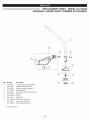
REPLACEMENT
PARTS - MODEL 316.792520
UNIVERSAL CURVED-SHAFT
TRIMMER ATTACHMENT
I
item Part No.
Description
1
2
3
753-04508
753-04282
753-04283
Lower Shaft Housing Assembly
Shield Mounting Hardware
Shield Assembly (includes 4)
4
5
6
791-180553
753-04284
791-610660
Blade Assembly
Outer Spool Assembly (includes 6)
Retainer
7
8
791-610317B
753-1155
Spring
inner Reel
9
791-153066B
Bump Knob Assembly
*
*
753-1156
791-180920
Reel & Line Assembly
0.095 Replacement Line
Items Not Shown
31
I
Your Home
product manuals and expert advice:
For troubleshooting,
managemylife
www.managernylife.com
For repair - in your home - of all major brand appliances,
lawn and garden equipment, or heating and cooling systems,
no matter who made it, no matter who sold it!
For the replacement parts, accessories and
owner's manuals that you need to do-it-yourself.
For Sears professional installation of home appliances
and items like garage door openers and water heaters.
1-800-4-MY-HOME
Call anytime,
®
day or night (U.S.A. and Canada)
www.sears.oorn
www.sears.ca
Our
For repair of carry-in
items
and electronics,
call anytime
Sears
Parts
1-800-488-1222
Home
like vacuums,
lawn equipment,
for the location
of your nearest
& Repair
(U.S.A.)
www.sears.corn
To purchase
a protection
1-800-827-6655
agreement
(U.S.A.)
Para pedir servicio de reparaci6n
a domicilio, y para ordenar piezas:
1-888-SU-HOGAR
(1-888-784-6427)
www.sears.com
®
(1-8oo-469-460s)
Service
Center
1-800-469-4663
(Canada)
www.sears.ca
on a product serviced
by Sears:
1-800-361-6665
(Canada)
Au Canada pour service
en fran(_ais:
I=800=LE=FOYER
(1-800-533-6937
www.sears.ca
S@SFS
® Registered Trademark / TMTrademark of KCD IP, LLC in the United States, or Sears Brands, LLC in other countries
® Marca Registrada / TMMarca de F&brica de KCD IP, LLC en Estados Unidos, o Sears Brands, LLC in otros paises
MCMarque de commerce / MDMarque d6pos6e de Sears Brands, LLC
No