1
VSB-70 Fast-Scan ]V Transceiver
••
OperatIng Manual
FOREWORD
Congratulations on your purcha~e of the VSB-70 Fast-Scan Television
Transceiver. It will provide you with excellent quality live amateur television transmitting and receiving capabilities.
',
To fully enjoy the benefits of the VSB-70, please read this manual carefully
before operating the transceiver. If you have qu~stions, I 'encourage you to contact an AEA authorized dealer or one of our technical support representatives at:
Advanced Electronic Applications, Inc.
P.O. Box C2160, 2006-196th S1. S.W.
Lynnwood, WA 98036
Customer Service: (206) 775- 7373
Fax: (206) 775-2340
Telex: 6972496 AEA INTL UW
CompuServe User 10: 76702,1013
'
73,
C. Mike Lamb, N7ML
President
CONTENTS.
Introduction
Front Panel Description
Rear Panel Description
Installation
Channel Selection ...
'.' ...
2
.. '..
.......
3
4
5
6
6
6
VSB-70 Mixing Crystals ...
Crystal Installation Procedure
Transmit Mode Operation
.
Receive Mode Operation
.
System Description
.
Transmitter Description
.
Receiver Description
Output Power Level Adjustment
Sync Stretcher and Zero Video Gain Sync Adjustments
Frequency Control
.
Schematic Diagram
.
Parts Pictorial
.
. .
. ·
·
·
. . .
Block Diagram
Warranty
. . . 14
15
.......
7
8
8
9
·
10
.
10
11
11
12
13
1
~
·~,~;:,~~#?::~~;:t~~!~:·>
,
"i"
••
'""
",
I~RdDU~TlON
1. INTRODUCTION
The AEA model VSB-70 is a Fast-Scan Television (FSTV) transceiver that
operates on the amateur 420 to 440 MHz band. The transmitter features two local
oscillator crystaJ-controlled channels a'rid an output of one watt PEP on sync
peaks. Receive operation can, transceive or use variable tuning.
In transmit, baseband NTSC video and audio·are converted to Vestigial
Sideband (VSB) video with the FM audio subcarrier in the 70 cm band. This is
the same format as used by broadcast television. Video cameras, Camcorders
and video cassette recorders with video and audio output jacks can be used to
generate the baseband video and audio for transmission. A separate front panel
microphone jack may also be used for audio input. Either color or black and white
video may be used. Television channel 3 or 4 may be used to monitor your broadcast signal.
If you live in an area where channel 3 is used by a commercial television station, your VSB-70 must be configured for channel 4, and vice versa. If you purchased the wrong configuration, you can change the local oscillator crystals and
retune the unit for the opposite configuration. See chapter 4, Channel Selection.
For receive, the 70 cm television signal is converted to either television channel 3 or 4. A standard color or black and white television is used for.reception.
The same television is used for monitoring your transmission. The VSB-70 uses
a GaAsFET preamplifier which provides for a system noise figure of less than 1.5
dB. Either crystal-controlled or VFO receive tuning may be selected •.
In addition to the video source and television set, a 13.6 volt regulated pow~r
supply and 70 cm antenna are necessary. AEA also offers the RLA-70 linear
amplifier with MPS-100 power supply and the 430-16 antenna to compiete your
A TV station.
To transmit, an amateur technician or higher class-license
2
is required.
r
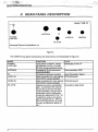
FRONT PANEL DESCRIPTION
2. FRONTPANELDESCRWTION
_~
Advanced Electronic Applicalions. Inc.
0 00
•••
•
-
VIDEOGAIN
XTAL
D!j&)fI30{l@
0
AUDIOGAIN
Fastscan TV Transceiver
RXTUNE-
VFO
Figure 1
Front panel controls, indicators and connectors are described below and illustrated in Figure 1:
NAME
..
control.
the
transceiver
on
the
rear
panel
when
transmittinq.
60 mA.
mode
when
keyed.
12V
F1/F2
crystals.
In the
VFO
AUDIO
INthe
and
VIDEO
IN@jacks
position,
receiver
frequency
is
determined
by
the
RX
TUNE
Push-button
resistor
Variable
Resistors
switch
Tunes
video
variable
camera
cable
for
external
600
ohm
Switches
between
transmit
and
Controls
power
to
video
camera
TYPE
FUNCTION
Selects
Adjust
video
crystal-controlled
andoscillator
audio
Toggle
switch
CAMERA
10-pin
In the
XT
AL
position
the
receiver
For
push-to-talk
2.5
mm
input
from
jack
+
13.6
VDC
input
power
1O-pin
connector
Plug-in
3.5
phone
3
oter
eceiver
::::~!l;,;t~~~':-J>':
REAR PANEL DESCRIPTION
3. REAR PANEL DESCRIPTION
•
+-1>
'
•
RF AlTN
ANTENNA
POWER
.' •
••
, Model VSB-70
TV
AUDIO IN
.
•••
VIDEO IN
+13.6 VDC
Advanced Electronic Applications, Inc.
Figure
2
The VSB-70 rear panel connectors are listed below and illustrated in Figure 2:
NAME
. ,
-.
db.
occurs
due
to
a 28
mast
mounted
the
is adjustment
reduced
to
about
16of
gain
turning
RF gain
ATTN
is typically
the
adjustment
db.
fully
CCW.
With
CCW
the
At
transceiver
full
receive
amplifier,
the
may
receive
be
the
lowered
conversion
gain
the
by
4
TYPE
FUNCTION
Connects
to5receive
70
television
cm
receiver
or !
Connector.
Type
FCenter
Coax
connector,
BNC
Screwdriver
adjustment
Barrel
jack,
mm,
J'1
jack
RCA
phono
video
signals
connection
for
audio
Adjusts
pin must
the
be
+
13.6
toantenna
preamplifier
+ 14
volts
Input
power
to
VSB-70.
-~
::..~ "
~
"...•
"',:;". '! . .c
..•+:".
INSTALLATION
4. INSTALLATION
Unpack the VSB-70 carefully. Check for signs of damage. If any damage is
noted, contact your dealer or the freight company. Keep any cartons and packing
materials for the ~ealer's inspection. COrl~ider keeping the container and packing
materials in case the unit must be shipped in the future.
The VSB-70 is designed to transmit and receive in the 420 MHz to 440 MHz
range. These instructions are for installation. Operation instructions are given onpage 7. Complete the installation as follows:
I Warning!
WarningJj
DO NOT TRANSMIT WITHOUT A LOAD!
The transceiver must NOT transmit Into a load with an SWR higher than
1.8:1. Damage may result from transmitting without an antenna or dummy
load •....
'.
1. Connect a coax cable from your 70 em antenna to the BNC ANTENNA connector on the rear panel of the VSB-70.
2.
To transmit live video: connect your video camera or Camcorder to the
CAMERA connector on the front panel of the VSB-70. Connect to VIDEO and
AUDIO jacks on the rear panel if a Camcorder with adapters is used. P!Jt
VIDEO/CAMERA switch in the appropriate position.
I
3.
To transmit VCR video: connect your VCR video and audio output signals to
the VIDEO IN and AUDIO in jacks, respectively, on the rear panel. Press
VIDEO/CAMERA push-button switch to VIDEO (latched out).
4.
Connect your television receiver to the Type F (TV coax) connector on the
rear panel
[NOTE!
NOTE! I
Your television receiver will display transmit and receive video on channel 3
or 4. The VSB-70 is delivered with the channel 3 jumper installed. To change to
the alternate channel, follow the instructions on page 6.
5.
If your camera does not have a built-in microphone, connect your microphone
to the MIC jack on the front panel.'
6.
If your microphone uses push-to-talk keying, connect the PTT line to the PIT
jack on the front panel.
5
....
;.'/~;~:}~~~/-'
CHANNELSELECTION
5.
•' ..
t:,_:,;:,:~~,~ _
CHANNEL SELECTION
VSB-70's are shipped with two local oscillator crystals installed. The crystals
will provide operation at 434.00 MHz (F1) and 439.25 (F2) with channel 3
enabled for receiving and monitoring tra,nsmissions. You may be in a service area
that requires selecting the other channel. If you have a local TV channel 3 or 4,
choose the unused channel. You must install the correct crystal and set the unit
to operate on the selected channel. The following procedures and table provide
the information you need to change the channel seiection ..
Crystals must be selected from the table below for the desired channel and
operational frequency. to change from channel 3 to 4 or vice versa, contact AEA,
Inc., to order the crystals you need.
VSB-70 MIXING CRYSTALS
INOTE!
NOTE!]
If you install or change any crystals, you must perform the CRYSTAL
LATION PROCEDURE below.
TRANSMIT FREQUENCY (MHzl
,
INSTAL-
93.000/090-893.00
89.75/090-889.75
88.50/090-888.50
..
91.25/090-891.25
90.00/090-890.00
91.6875/090-891.68
94.500/090-894.50
CHANNEL
43 (MHzl/AEAoart#
93.1875/
CHANNEL090-893.18
(MHzl/AEAoart#
The above crystals can be ordered direct from AEA or through your 19.cal
dealer. Suggested price: $15 each.
The selection of channel 3 or 4 for display on your television receiver is determined by the position of a jumper on the circuit board inside the VSB-70. To
change the current channel selection of your VSB-70, perform the following:
1.
Remove the power cord and the cover from VSB-70 ..
2.
Refer to page 12 to locate jumper JP2.
3.
Install JP2 to connect the center post to either "3" or "4" for the channel
desired.
4.
Perform the crystal installation procedure below.
CRYSTAL INSTAllATION
PROCEDURE
Equipment required for tuning: Bird or PEP wattmeter (1 watt), .075 inch nonmetallic tuning tool, desired crystal.
Do not adjust any inductors or variable capacitors other than the ones
referred to in this manual's tuning procedures (this page and page 10) as the cir~
cuits are factory tuned.
The VSB-70 is delivered with F1 = 434 MHz and F2 = 439.25 MHz as the
transmit/receive operational frequencies. The unit is configured for either channel
3 or 4. Check the outside of the box to check which channel your VSB-70 is con-
6
· TRANSMIT
MODE OPERATION
figured forThe other local oscillator crystals are purchased for optional TXlRX frequencies and TV channels. To install a crystal, complete the following:
1. Remove the power cord, then remove the top cover.
2.
Use page 12 to locate the crystal socket (Y1 or Y2) and the corresponding
ADJUST (F1. or F2) on the circuit bQ~rd..
3.
Install the new crYstal in th~ socket as desired.
4.
Connect a video camera, Camcorder or VCR t~ the appropriate connector.
5.
Connect a power meter and reasonably well-matched load (less than 1.8:1
SWR) to the antenna coax connector of the VSB-70 to read transmit power.
6.
Select the desired crystal by pressing the F1/F2 push-button.
7.
Press RECEIVE/XMIT
push-button switch to XMIT (red LED on).
8. Turn the power on and begin transmitting.
9.
Using a standard .075 inch hex non-metallic tuning tool (available at most
electronic supply stores), turn the F1 or F2 ADJUST (as appropriate) for maximum output signal on your power meter. When the signal strength is maximum, the oscillator is correctly tuned. If a series of lines or dots show on the
received picture, slightly retune the F1 or F2 adjust, accordingly.
6. TRANSMIT MODE OPERA TION
IWARNING!
WARNING!
I
NEVER TRANSMIT WITHOUT A LOAD!
Your VSB-70 needs a dummy load or antenna wIth a relatively close ImEquipment damage may
pedance match connected before transmitting.
resultfrom transmitting
Into no load or a load resulting In an SWR of more
than 1.8:1!
1. Check power, camera or VCR, microphone, television receiver and antenna
connections to VSB-70 connectors.
2.
Press PWR OFF/PWR ON push-button switch to ON (red LED lights).
3.
To transmit live with your video camera, press the CAM OFF/CAM ON pushbutton switch ON (latched in).
4.
Check your video camera or Camcorder for power.
5.
Press the VIDEO/CAMERA
push-button switch to CAMERA (latched in).
6. To transmit VCR video, press the VIDEO/CAMERA
(latched out).
7.
push-button switch
Select transmit frequency:
F1 = 434.0 MHz, F2 = 439.25 MHz. Check that the F1/F2 switch is in the appropriate position.
Optional frequencies: 421.25,~r
439.25 MHz (if installed). Check that
F1/F2 switch is set to the appropnate position ..
7
8.
Press RECEIVE/XM1T push-button switch to select transmit mode (latched In,
red LED lights).
9.
Begin transmitting. On your television receiver, check for video and audio signal quality and strength.
10. Adjust VIDEO GAIN AND AUDIO GAIN controls for signal quality and
strength ...
If you are using a Bird or equivalent power meter which ,reads average RF
power, it will read 0.6 watts minimum with a black video source. This is the
equivalent of one watt PEP on sync peaks.
7. RECEIVE MODE OPERA TION
1.
Press the RECEIVE/X~IT
switch to receive mode (latched out, LED off).
2.
Select transmit frequency:
F1 = 434.0 MHz, F2 = 439.25 MHz. Check that the F1/F2 switch is in the appropriate position.
Optional frequencies: 421.25, 426.25 or 439.25 MHz (if installed). Check that
F1/F2 switch is set to the appropriate position.
If you do not have a local oscillator crystal for the frequency yo~ wish to
receive, or the transmitting station's signal does not appear clearly, tum the RX
TUNE switch to VFO and adjust for best signal quality. The operating range of
the VFO is from 420 to 440 MHz.
8. SYSTEM DESCRIPTION
The VSB-70 provides all of the signal conditioning necessary to perform
NTSC video composite television transmission and reception in the 420 to 440
MHz band. The system is designed around a single conversion hardware architecture which utilizes the same television channel (3 or 4) for transmit and
receive signal conversion. Vestigial Sideband (VSB) filtering is utilized to minimize adjacent channel interference. The bandpass filter is tailored to the characteristics that a television receivefis designed to receive.
Two local oscillator crystal sockets are provided for transmission and reception modes, and a VFO is provided for reception of signals which' have drifted
such that crystal-controlled reception is difficult or impossible, or when different
transmit and receive frequencies are used, such as when using a repeater.
A linear Class A output amplifier has been optimized for one watt Peak Envelope Power (PEP.) on sync peaks with extremely low levels of intermodulation
distortion. Front-end reception is performed with a low-noise GaAsFET
preamplifier which provides the system with an overall receiver J:loisefigure of
less than 1.5 dB within the 420-445 MHz band
The functional operation of the transmit and receive modes is described
below. References are made to the component location diagram (Figure 4). The
block diagram (Figure 5) and schematic (Figure 6) may also be llseful.
8
· ·~1.~~~~Bfg··' .~."'."",
, ...""""._~,,: .":-;,"~':.1-.;~<
,
I ....
TRANSMITTER
SYSTEM DESCRIPTION
DESCRIPTION
Video and audio signals may be input from a video camera, Camcorder or
VCR. Video and audio signals (baseband) from a video camera or Camcorder
are input via a standard 1O-pin Canon connector on the front panel of the VSB70. Camera or VCR signals are input as separate video and. audio signals to the
VIDEO IN and AUDIO IN jacks on the rear panel. Audio input from an extemal
microphone may be added via the MIC front panel jack. PIT may be utilized to
switch the VSB-70 into transmit mode from an external microphone.
Video baseband signals are input to an amplifier which extends (restores) the
sync peaks to compensate for external amplifier gain compression' or cabling
loss. The gain for the amplifier is variable and accessible from the front panel via
the VIDEO GAIN control. The expansion level is adjusted with R-39 (internal
potentiometer). Audio_baseband signals are amplified with a variable gain
amplifier as well. The gain for the audio amplifier is adjustable from the front
panel via the AUDIO GAIN control.
The video baseband signal modulates·a crystal controlled IF carrier frequency
for channel 3 or 4. The audio baseband signal modulates a veo at 4.5 MHz. The
modulated signals are then mixed to form a double-sideband video composite signal at either 61.25 MHz (channeI3) or 67.25 MHz (channeI4). The selection of IF
channels 3 or 4 is determined by the position of jumper JP2 and the crystal installed in the channel 3 or 4 oscillator (see page 12).
The IF signal is then VSB filtered. The Surface Acoustic Wave (SAW) Filter
eliminates the major portion of the lower sideband of the IF signal. The resultin,g
signal is not a true Single Sideband (SSB) signal as a portion of the lower video
sideband is retained. The primary purpose in employing VSB is to reduce or
eliminate interchannel interference while retaining significant video information in
the lower sideband of the IF carrier.
The IF output of the VSB filter is amplified and then up- converted to the RF
output frequency by mixing with one of the two local oscillators (LO). Selection of
the LO frequency is done with the front panel F1/F2 switch. The LO frequency is
generated from a crystal oscillator which has been multiplied by a factor of four.
For transmission monitoring, the IF information presented to the mixer is
amplified then filtered to remove the LO and both RF sidebands. The user may
view transmitted IF signals on channel 3 or 4 of any standard US television set
from the TV connector located on the rear panel.
For transmission the desired RF sideband resulting from the mixing process
is amplified then filtered to remove the LO and lower sideband mixing products.
The RF carrier then drives the RF power amplifier, which consists of two discrete
actively biased transistor amplifiers 02 & 04. The amplifier will deliver one watt
PEP on sync peaks (black video) with a lower audio sideband attenuation of better than 42 dB. The user may change the output power by adjusting C104 (see
Figure 4) to accommodate external power amplifier requirements. If power output
is increased above 1 watt PEP, amplifier distortion specifications are not guaranteed.
9
RECEIVER DESCRIPTION'
RF signals present at the antenna connector on the rear panel are switched
to the double tuned low-noise GaAsFET preamplifier. The preamplifier has been
optimized for gain, thermal noise and image rejection. As a result, the receiver
conversion noise figure is better than 1.5 dB in the 430 MHz band.
The RF signal is then down-converted to a channel 3 or 4 IF by mixing with a
user-selectable LO. RX TUNE on the front panel may be used to manually tune in
a station which has drifted to the extent that reception with one of the crystal oscillators is compromised. The desired IF sideband is filtered to remove the LO and
image sideband then presented to the TV output connector on the back panel.
The signal at the TV connector may be viewed on channel 3 or 4 of any standard
US television set.
OUTPUT POWER LEVEL ADJUSTMENT
IWarning!
WarninQI]
Adjust only C104, L13, L14, R39, and R98 per the Instructions in this manual.
Any other adjustments should be made only by a qualified technician using a
spectrum analyzer, tracking generator, synthesizer, frequency generator, dummy
load and wattmeter. Currently, a $50.00 charge will apply to all units which are
returned to AEA for re-tuning ...
Your VSB-70 has been delivered with the output power preset to one watt I
PEP on sync peaks into a 50 ohm load. There are occasions when it is neces- .
sary to adjust the output power to a different level (such as interfacing with an external power amplifier). The output power level may be adjusted by rotating C104
(see Figure 4) while a black level signal is input to the unit.
The procedure for adjusting the output power level is as follows:
1.
. 2.
Follow the instructions for TRANSMIT MODE OPERATION using a video
camera or Camcorder for the signal sourc;e (i.e. turn on the unit and optimize
the picture quality) .
Cover the lens of your video camera or Camcorder with a black lens cap. This
provides the black level input signal to the unit.
Adjust C1 04 (see page 12) with the non-metallic tuning tool until the power is
at the desired level. A power meter must be used to determine the absolute
power level. If you have a high-quality PEP power meter, then adju$t the power
level directly from the indicated output reading. If you have a Bird (or equivalent)
power meter, then scale the desired level relative to 0.6 watts. For example, a
Bird power meter will read 0.3 watts for a 0.5 watt PEP (0.6 x 0.5) output power
level.
IWarning!
The variable capacitors
they can become unstable
capacitors!
10
Warning! I
are not designed to be repeatedly adjusted
and loos~. Do not repeatedly tune these
-
•:,"'~,;::.-',~~~.-.~:~.
I
~. ~
" . ,,.. ,..~",
.•..;..~
SYSTEM DESCRiPTION
SYNC STRETCHER AND ZERO VIDEO GAIN SYNC ADJUSTMENTS
Two internal controls adjust the sync signal characteristics. Adjusting R98
CCW (conter-clockwise) will increase the level of the synchronization pulse to
compensate for compression of the signal in external amplifierS. It is recommended that the control be left in the full CW (clockwise) position as operation of
an amplifier at maximum pO,wers~yerelydegrades the linearity of the amplifier.
A circuit has been incorporc;l.ted in the VSB-70 that provides sync pulses even
when the front panel video gain control has been reduced to,zero. The internal
control R39 sets the sync level at zero video gain. 'An oscilloscope is necessary
for adjustment of this control. Monitor the baseband video on pin 2' of U2 with normal video input. Set the front panel video gain control fully CCW and adjust R39
for the same level of sync pulses.
FREQUENCY CONTROL
TransmiVReceive signaJ~ are mixed with frequenc!es generated in a separate
oscillator section that provides two/three switched selections to match transml,ssion or reception frequencies for Amateur Television. YourVSB-70 was delivered
with two crystals (F1 & F2) which provide operation at 434 and 439.25 MHz,
respectively.
For an example' of the frequency control circuit operations, assume you will
be using channel 3:
I
•
The 93.1875 MHz F1 frequency is doubled, filtered, doubled again
and filtered producing 372.75 MHz to the mixer.
•
The 372.75 MHz is added to the 61.25 MHz transmit frequency by the
mixer giving a final transmit frequency of 434 MHz. '
•
The same 372.75 MHz signal is subtracted from a 434 MHz'receive
signal giving the 61.25 MHz channel 3 frequency to your television
receiver.
11
I ••
l
~."'.~,
f.i"·".'
d;~~~;"
~,.
",,~~
.••.
r•.,..
,.J~~.
,;:',
B""·1l.,
~~~i"
~;l -
1:"
.,
••
Ii"
.II
"1
HIC
"
c;.l;-]
-
LJI
•• e'" en
...
1~
,,.,.
.,.
41,
~'I'
,, p"".
.... ,.
""
hen
Jlo-h
,
..
...enf..~
1";;.4 ~...~
<>-
IZ.5V
~
e.~
---
* ~ll,0''''
AUtfIO<i?
IN"
1.
.•.•.
'"
lIl"
•••
vfflEO
~,
IN
t:
i~;",
!~~.(1·"
-
•••••
r+J"
'i::'
y.
.J4
([
G
W
[il
Q:
o
::f:
([
U
'I~U
-
" ~I.'
...
-:;:- .., ..,
=~
"
•
.lZ-'''~
~.
0'3
."
-<I
.•.
2~;).
'U11
•••
~ b, •
..6
PH
cu
TELE-
0-
@
oJ'
VISION
_
+13.6
VOC
.11
:2:
.
<
F~Kr 'a:
I\t~"
"""'
.... .CJ<
~'I,,,.'.
:,~-' " -0
;·'l::,t'o
, ~'''i·:''J~i.,1.',·~.~.<
.,
';::E
w
J:
o
'"~
...
•••
...
...
-c:-r
.../ ~:.L ..:
'~ZI_
~'* ~ ,,":,
..
"'1
NOTES:
I.
Z.
- ,....•
~
'1
-
"
LAST USEO.REF. OESIG:
ellS
L33
Uq
RIBS
OZI
Dq
LIZ. 06
IU,
!!E!!7
J8
UNUSED REF. DES (G •:
R46. RSS. RSe.. RS7. R60.
lIl.
~'lP
Im
ANTENNA?
I.;
i~i,::.
--"
AEA
!i
1
I,.:
..~
~:;:.
C 0 I AGRAH
RBI •
'00
~~"
APPLICAT IONS.
ADVANCEO--rCt:CTRONIC
INC.
SCHEMATl
9. SCHEMATIC ~fAGRAM
......-
~•• ';'1.'1.
~d
'.~:-t~.i.
;: ...• ,
f
"
,r-
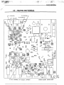
PARTS PICTORIAL
.
r·
10. PARTS PICTORIAL
Fl CRYSTAL
Rl.I
o
Fl
Rl3
(CHANNEL 3/4 SELECT JUMPER)
POWER ADJUST CAPACITOR
"
"-':'
~';~I':'
;,.,.
.•..
(.~
CAMERA.
CAMCORDER or VCR
~,
VESTIGIAL
SIDE
BAND
FILTER
,.'.,'
6Z
ItHZ
430
HIXEIl
DIPLEXER
DJPLEXER
BAND
PASS
FILTER
~
••••
~
,'-~
.:':~"~'"
\to
CJ
·I:.~,:
.
.. ' ..;'.
'.-.•.
I~-·~·o-;c.;
....
~~.~;:~
:
"'
~
\.
~(
.cae ItHZ
~
~~~~;'
.-
31Z
Q
; :-j'-
'~-;,l
11HZ
TO TELEVISION
.
~~~ '5:
,,'
,
q3
~
o
RECEIVER
11HZ
.....,J
CO
t
•
,...
,...
::.,'!, .
~:
-
...
'
01
I
I"
IDSCILLATOR~
COPYRIGHT
BY AOVANCED
ELECTRONIC
APPLICATIONS.
INC.
1'l8'l
('
~
,
r"
\
--,
.....
12. WARRANTY
LIMITED WARRANTY
ADVANCED ELECTRONIC APPLICATIONS, INC. warrants to the original
purchaser that this product shall be free from defects in material or workmanship
for ninety days from the date of original purchase. In order to obtain warranty service: 1) Complete and mail the warranty registration card within 10 days to Advanced Electronic Applications, Inc., and 2) Send written notification to the
address below or telephone as soon as possible after discovering a possible
defect:
Advanced Electronic Applications, Inc.
Attention: Service Department
2006-196th S1. S.W.
Lynnwood, WA 98036
The written notification must include a copy of the invoice. Include a description of the defective part or condition, with details of the electrical connections to
associated equipment and list such equipment. Please enclose your name,
,
phone number, and address. Shipping charges for any parts or units submitted·
for replacement under this warranty must be paid by the purchaser.
Correct maintenance, repair and use are important to insure proper performance from this product. Carefully read the Instruction Manual. This warranty
does not apply to any defect AEA determines is caused by 1) Improper maintenance or repair, including the installation of parts or accessories that dO not conform to the quality and specification of the original parts; 2) Misuse, abuse,
neglect, or improper installation; 3) Accidental or intentional damage. The field installation of circuits according to the explicit instructions of AEA will not nullify this
warranty.
All implied warranties, if any, terminate ninety days from the date of original
purchase. AEA is not reponsible for damage to other equipment or property or
any other consequential damages. Some states do not allow limitations of how
long an implied warranty lasts or do not allow the exclusion of incidental or consequential damages, therefore, the above limitations and exclusions may not apply
to you ..
This warranty gives specific legal rights. You may also have other rights
which vary from state to state.
14