1
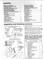
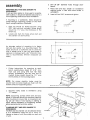
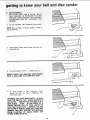
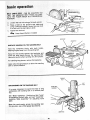
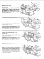
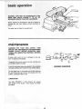
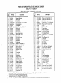
SAVE THIS MANUAL
FOR FUTURE
REFERENCE
BELT AN D DISC
SANDER
Serial
Numbe[
Model and serial
number may be found on
the back side of
the base.
You should record both
model and serial number
in a safe place for
future use.
BELT A
SANDE
CAUTION:
DISC
o assembly
Read GENERAL and
ADDITIONAL
SAFETY
INSTRUCTIONS
_arefuily
• operating
• repair parts
!
Sold by SEARS,
Part No, SP5137
ROEBUCK
AND
CO., Chicago,
tL. 60684 U.S.A.
i
i i ii•i i iiii
SEARS, ROEBUCK AND CO:, 698t731A. Sears Tower. Chicago, IL 60684
general safety instructions for power tools
1.
KNOW YOUR POWER TOOL
Read and understand
the owner's
manual and
labels affixed to the toot. Learn its application
and limitations
as welt as the specific
potential
hazards peculiar to this tool.
2.
GROUND ALL TOOLS
This tool
is equipped
with
an approved
3:
conductor
cord and a 3-prong grounding
type
plug to fit the proper grounding
type receptacle.
The green conductor
in the cord is the grounding wire, Never connect the green wire to a live
terminal.
3_ KEEP GUARDS IN PLACE
-- In working
order, and
and alignment,
4.
5:
in proper
adjustment
REMOVE ADJUSTING
KEYS AND WRENCHES
Form a habit of checking
to see that keys and
adjusting
wrenches
are removed
from tool
before turning it on.
KEEP WORK:AREA CLEAN
Cluttered:
areas and benches
invite accidents.
Floor must not be slippery
due to wax or sawdust.
6.
AVOID DANGEROUS
ENVIRONMENT
Don't use power toels in damp or wet locations
or expose
them:to
rain, Keep work area _well
lighted,
Provide
adequate
surrounding
work
space,
7.
KEEP CHILDREN
AWAY
All visitors shoUfd be kept a safe distance
work area,
8.
9.
MAKE WORKSHOP CHILD-PROOF
-- with padlocks,
master
switches,
moving starter keys.
DON'T FORCE TOOL
It will do the job better
which it was designed.
and safer
10. USE RIGHT TOOL
Don't force tool or attachment
not designed for,
from
Z87.1) at alt times.
Everyday
eyeglasses
only
have impact
resistant
lenses,
they are NOT
safety glasses. Also. use face or dust mask if
cutting
operation
is dusty, and ear protectors
(plugs
or muffs)
during extended
_er_ods of
operation.
13. SECURE WORK
Use clamps or a vise to hold work when practical. It's safer than using yoL_r hand, frees both
hands to operate tool,
14. DON'T OVERREACH
Keep proper footing
to do a job it was
11. WEAR PROPER APPAREL
Do not wear loose clothing,
gloves, neckties or
jewelry
(rings, wristwatches)
to get caught in
moving
parts. NONSLIP
footwear
is recommended. Wear protective
hair covering
to contain long hair, Roli
long sleeves
above the
elbow.
12. USE SAFETY GOGGLES (Head Protection)
Wear safety goggles
(must comply
with
ANSI
at all times,
16. DISCONNECT
TOOLS
before
servicing;
when changing
such as blades, bits, cutters, etc.
17. AVOID ACCIDENTAL
STARTING
Make sure switch is in "OFF"
plugging in.
accessories
position
before
18,_ USE RECOMMEN DED ACCESSORIES
Consult the owner's
manual for recommended
accessories,
Foltow
the
instructions
that
accompany
the accessories,
The use of improper accessories
may cause hazards,
19. NEVER STAND ON TOOL
Serious injury could occur if the tool is tipped
or if the cutting tool is accidentally
contacted.
Do not store materials
such that it is necessary
reach them,
or by re-
at the rate for
and balance
15. MAINTAIN TOOLS WITH CARE
Keep tools sharp and clean for best and safest
performance.
Follow instructions for lubricatinq
and changing accessories.
above or near the tOO!
to stand on the tool to
20. CHECK DAMAGED PARTS
Before further use of the tool. a guard or other
part that is damaged should be carefully
checked to ensure that it witl operate properly
and
perform
its intended
function.
Check for alignment of moving parts, binding of moving
parts.
breakage of parts, mounting,
and any other conditions that may affect its operation.
A guard or
other part that is damaged should be properly
repaired or replaced,
21. DIRECTION OF FEED
Feed work into a blade or cutter against
the
direction
of rotation of the blade or cutter only.
22. NEVER LEAVE TOOL RUNNING UNATTENDED
Turn power off. Don't leave tool until it comes
to a complete
stop.
2
additionaU safety instructions
disc sander
f.
- Safety is a combination of operator common sense and
alertness at aft times when the sander is being used.
WARNING: FOR YOUR OWN SAFETY, DO NOT
ATTEMPT TO OPERATE YOUR BELT AND DISC
SANDER UNTIL IT IS COMPLETELY ASSEMBLED
AND INSTALLED ACCORDING TO THE INSTRUCTIONS .... AND UNTIL YOU HAVE READ AND UNDERSTOOD THE FOLLOWING:
g.
h.
Page
1. General Safety Instructions for Power Tools.
2. Getting to Know Your Sander ...........
3. Basic Operation .......................
4. Maintenance ..........................
i.
2
11
13
16
j.
k.
°
Stability of Machine
If there is any tendency for the machine to tip over
or move during certain operations such as when
sanding long heavy boards, the sander should be
bolted down.
1.
m.
6. Location
The machine should be positioned so neither the
operator nor a casual observer is forced to stand
in line with the sanding belt or disc. This machine
is intended for indoor use only.
7,
8_
Kickback
When sanding on the Disc, always apply the workpiece left of center to the left side of the disc. Applying the workpiece to the right side could cause
it to fly up (kickback) which could be hazardous.
When sanding on the sanding belt, never apply
the end of a workpiece to the idler pulley which
can result in a kickback.
Protection: Eyes, Hands, Face, Ears and Body
a. Always wear safety goggles (not glasses)
that comply with ANSI Z87.1. Wear face shield
if operation is dusty. Wear ear plugs or muffs
during extended periods of operation. Do not
wear gloves, jewelry or watches. Roll long
sleeves above the elbow. Tie back long hair.
b. Do not sand pieces of material too small to
hold by hand.
c. Avoid awkward hand positions, where a
sudden slip could cause a hand to move
into sanding disc or belt.
d. Never climb on the machine.
e. Never turn your Sander "ON" before clearing the belt table and worktable of all
objects.
n.
o.
g,
for bett and
Make sure the sanding belt runs in the
right direction (directional arrow on back
side of belt). Always have the tracking
adjusted correctfy so that the belt does
not run off the pulleys.
Hold the work firmly when sanding on the
belt and against the worktable when sanding
on the disc.
Always adjust the worktable to within a
maximum of 1/16-inch of the sanding disc
or belt.
When sanding a large piece of material,
provide additional support at tabfe height.
Never leave the machine work area when
the power is on, before the machine has
come to a complete stop, or without removing and storing the switch key.
Do not perform layout, assembly or setup
work on the table while the sander is
operating.
Turn sander "OFF" and remove plug from
power supply outlet before installing or
removing an accessory.
Use only RECOMMENDED ACCESSORIES
listed on page 19.
Always keep guards in place when operating
sander.
Tighten securely all work supports before
sanding.
If any part of this Belt and Disc Sander should
break, bend, or fail in any way or any electrical
component fail to perform properly, or if any is
missing, shut off power switch, remove power supply cord from power supply and replace damaged
missing and/or failed parts before resuming
operation.
10. Do not sand with the workpiece unsupported. Support it with the backstop or worktable. The only
exception is curved work performed on outer end
of belt (idler pulley).
11, To avoid entanglement in spindle, do not operate
sander with sanding plate and/or guard removed.
CAUTRON: This Belt and Disc Sander is designed
to sand wood or wood like products only. Attempts
to sand or grind other materials could result in fire,
injury or damage to the product.
S
12_ Think Safety _ ::_:
Safety is a combination of operator common
sense and alterness at all times when the
sander is in operation.
WEAR
YOUR
The operation of any power tool can result in foreign objects being thrown into the eyes, which
can result in severe eye darnage. Always wear
safety goggles
(not glasses)complying
with
ANSI Z87.1 (shown on Package) before beginning
power tool operation,
Safety Goggles are available at Sears retail or catalog stores,
11
IIllllll
[
t
WARNING: DO NOT ALLOW FAMILIARITY (GAINED FROM FREQUENT
BECOME COMMONPLACE.
ALWAYS REMEMBER THAT A CARELESS
SUFFICIENT TO INFLICT SEVERE INJURY;
....
i j L
¸
•
READ AND
II
,........
FOLLOW
'"_"
THE
WARNINGS
' "'"
L
USE OF YOUR MACHINE) TO
FRACTION OF A SECOND tS
i
.....
lUll
THAT APPEAR ON THE TOOL:
I
j L__
I
II11.
....
L_J-
_J.
L_I
FOR YOUR OWN SAFETY:
1. READAND UNDERSTAND OWNER'S MANUAL
BEFORE OPERATINGMACHINE.
2. WEAR SAFETY GOGGLES AND DUST MASK.
3. MAINTAIN1/16"MAXIMUM CLEARANCE BETWEEN
TABLE AND SANDING BELT OR DISC.
...............
4. AVOID"KICKBACK" (WORKPIECE THROWN AT
YOU)--DO NOT USE RIGHT HALF OF DISC.
5. ALWAYSSUPPORT WORKPIECE WITH "BACKSTOP" OR "WORKTABLE.'"
6. DONOT WEAR GLOVES, NECKTIE OR LOOSE
CLOTHING.TIE BACK LONG HAIR.
,,,,
......
Iql
E82443
r,
cations and electricaJ
This machine is designed to use, and is equipped with, a 3450 RPM motor, it is wired for operation on 110-120 volts, 60 Hz., alternating
current.
(TOOL MUST NOT BE CONVERTED TO OPERATE ON 230 VOLT).
For replacement
manual.
motor
refer to parts list in this
CONNECTING TO POWER SUPPLY OUTLET
This machine must be grounded while in use to
protect the operator from electric shock.
This plug requires a mating
ed type outlet as shown.
WARNING:
IF NOT PROPERLY
GROUNDED
THIS POWER TOOL CAN CAUSE AN ELECTRICAL SHOCK PARTICULARLY
WHEN USED IN
_DAMP LOCATIONS
CLOSE TO PLUMBING.
IF
N ELECTRICAL SHOCK OCCURS THERE IS
THE POTENTIAL OF A SECONDARY HAZARD
SUCH AS YOUR HANDS CONTACTING
THE
SANDING SURFACE.
If power cord is worn or cut, or damaged
way, have it replaced immediately.
Your unit is for use on 110-120 volts,
plug that looks like below.
in any
and has a
3-PRONU
PLUG
PRON G
'_,
PROPERL¥
GROUNDED
3-PRONG OUTLET
This power tool is equipped with a 3-conductor
cord and grounding
type plug which
has a
grounding
prong,
approved
by Underwriters'
_.boratories
and the Canadian Standards Associ;iion, The ground conductor
has a green jacket
and is attached to the tool housing at one end
and to the ground prong in the attachment
plug
at the other end.
ground-
tf the outlet you are planning to use for this
power tool is of the two prong type, DO NOT
REMOVE OR ALTER THE GROUNDING
PRONG
IN ANY MANNER.
Use an adapter as shown
below and always connect the grounding lug to a
known ground.
It is recommended that you have a qualified electrician replace the TWO prong outlet with a properly grounded THREE prong outlet.
Plug power cord into a 1 t0-120V properly grounded type outlet protected by a 15-amp. fuse or circuit breaker.
WARNING:
DO NOT PERMIT
FINGERS
TO
TOUCH THE TERMINALS
OF PLUGS WHEN
INSTALLING OR REMOVING THE PLUG TO OR
FROM THE OUTLET.
3-conductor
GROUND!NG LUG
3-PRONG
MAKE SURE TH!S_S
PLUG
CONNECTED TO A
KNOWN GROUND
ADAPIER
An adapter
ing plugs
as illustrated is available
to 2-prong receptacles.
for connect-
WARNING: THE GREEN GROUNDING LUG EXTENDING FROM THE ADAPTER MUST BE CONNECTED TO A PERMANENT GROUND SUCH AS
TO A PROPERLY GROUNDED
OUTLET BOX.
NOT ALL OUTLET BOXES ARE PROPERLY
GROUNDED.
If you are not sure that your outlet box is properly grounded, have it checked by a qualified electrician.
NOTE: The adapter illustrated
is for use only if
you already have a properly grounded
2-prong
receptacle. Adapter is not allowed in Canada by
the Canadian Electrical Code.
The use of any extension cord wilt cause some
loss of power. To keep this to a minimum and to
prevent overheating and motor burn-out, use the
table below to determine the minimum wire size
(A.W.G.) extension cord.
Use only 3 wire extension cords which have 3prong grounding
type plugs and 3-prong receptacles which accept the tools plug.
Length of the
Conductor
Wire Sizes Required
(American Wire Gage Number)
120V
0 - 25 Feet
26 - I00 Feet
Over 100 Feet
Lines
No, 14
No. 12
No. 8
:Squaring Table::_sSembly:,
.........
...........
11
ReP!aci_g_The:i:::Sanding:Belt : :::
N.........:
2
: DISC SANDER:
IOTOF
ELECTRICAL REQUIREM E
UNPACKING AND CHECKING
ASSEMBLY
........
_5
MTENTS . :::... 6
Mounting Belt and Disc Sander
To Workbench ...............................
AND
:::, ::.: ... .....
Positioning Beii Table... : ::..
Belt Table Stop:. : ::.. .........
;,..
13
........
: .... ,.. 15
! .... ;. i .......
16
Surface Sanding On
Sanding Belt ................................
End Sanding On The
Sanding Belt ................................
Sanding Curved Edges .......................
MAINTENANCE ..............................
Lubrication ..................................
TROUBLESHOOTING
........................
RECOMMENDED ACCESSORIES .............
REPAIR PARTS ..............................
7
Clamping Belt And Disc Sander
To Workbench ...............................
installing Timing Belt ..........................
installing Pulley Cover .........................
installing Sanding Disc Plate ..................
Installing Backstop ............................
Installing Table Assembly ....................
:::;: ::::;
7
8
9
9
10
10
16
16
17
18
18
19
19
20
unpacking and checking contents
TOOLS
Model 113.226424
Bert and Disc Sander
complete in one carton.
NEEDED
is shipped
Separate all parts from packing materials
and
check each item with illustration
and "Table of
Loose Parts." Make certain all items are accour'_ _
ed for, before discarding any packing material.
If any parts are missing,
do not attempt
to
assemble the Belt and Disc Sander, plug in the
power cord, or turn the switch on until the missing parts are obtained and installed correctly.
WARNING:
FOR YOUR OWN SAFETY, NEVER
CONNECT PLUG TO POWER SOURCE OUTLET
UNTIL ALL ASSEMBLY STEPS ARE COMPLETE
AND UNTIL YOU HAVE READ AND UNDERSTOOD THE ENTIRE OWNERS MANUAL.
A
B
ITEM
TABLE OF LOOSE PARTS
QTY.
A
8
C
D
E
F
G
Belt and Disc Sander Assembly .,.
Owner's Manual ...............
Table Assembly ................
Sanding Plate .................
Sanding Disc ..................
Table Support Rod .............
Bag Assembly Part #507771 .....
Containing the following parts:
Clamp-Bolt ....................
Switch, Key ...................
Screw Soc. Set 5116-24X318 ......
Wrench, Hex "L" 118 ............
Backstop .....................
Washer, 114" . .................
I Bolt, Flex I14-20X112 ............
Setscrew I14-20XI14" . ..........
• Screw 114-20X1-3!4" . ...........
Lockwasher 1/4" , ..............
,
1
1
1
t
1
1
: ::
:
::
::
::
D
: : :
: : :
'
::::: :::: :
_F:
: ::::::::
:::_: ::::::::
" :
G:
6
H
J :
Pulley Cover ,,.................
TimngBelt
...................
I
1
1
1
!
1
1
1
1
1
1
1
1
assembly
MOUNTING BELT AND
WORKBENCH
If belt and disc sander
nent location, it should
firm supporting surface
DISC SANDER TO
is to be used in a permabe fastened securely to a
such as a workbench.
3,
Drill (4) 3t8"
bench.
4,
Place belt and disc sander on workbench
aligning
holes in feet with holes drilled in
workbench.
5.
Insert all four 5f16" screws and tighten.
If mounting
to a workbench, holes should be
drilied through supporting
surface of the workbench using dimensions illustrated.
°
.
"_
Locate and mark the holes where
disc sander is to be mounted.
3/8"
5-5,q_6"
holes
DtAMET
E"_
through
work-
+
(4t ROBES
1
Each leg should be bolted securely
using
5116" hex nuts (not included). Screw length
should be 11/2" plus the thickness
of the
bench top.
diameter
_-_-
} 3-1 1 ,"16 " --_
belt and
24 " M!N
An alternate
method of mounting
is to fasten
belt and disc sander to a mounting
board. The
board should be of sufficient
size to avoid tipping of sander while in use. Any good grade of
plywood or chipboard with a 3f4" minimum thickness is recommended.
(Thinner chipboard
can
break.)
JJllllll
,
HI
I
MI
I
J_lllI[IIL!IIL
I
3,'8 _'DAMET[Ri4_HOLES
,
IIII
Follow instructions
for mounting
to workbench, substituting
a board 18" x 24" minimum size and using 5f16 inch flat head
screws, tockwashers,
and hex nuts (not included). Screw length should be !1/z " plus
the thickness of the mounting board.
NOTE: For proper stability,
hopes must be
counter sunk so screw heads are flush with the
bottom surface of supporting board,
..... Illl
2.
5°7/16"
Securely clamp
"C" ciamps.
Illl
board
to workbench
MOUNTING HOLES
I_I '1_'
using
MOUNTING
NOTE: Supporting
surface where belt and disc
sander is mounted should be examined carefully
after mounting to insure that no movement during use can result. If any tipping or walking is
noted, secure workbench
or supporting
surface
before operating belt and disc sander.
CLAMPING BELT AND DISC SANDER TO
WORKBENCH
The Belt and Disc Sander can be clamped directly to a workbench
using two (2) or more "C"
clamps on base of unit (one clamp on each end
of unit).
HOLES
WORKBENCH
!
1
]u Irl
2, Place right hand under motor pulley and lift pulley
and belt upward. Using left hand, place belt onto
top pulley.
i
i
i
3, The motor is spring loaded so proper tension
wil! be maintained between belt and pulleys
at all times.
PULLEY COVER
INSTALLING
PULLEY COVER
1.
Locate
the
114-20xl -3/4"
2.
Place pulley cover into position shown and
fasten with one screw. Do not overtighten.
INSTALLING
pulley
SANDING
cover
and
one
screw
DISC PLATE
SET SCREW
WRENCH
1.
Locate sanding disc plate, sanding disc, one
setscrew 1/4-20xl/4 inch, and a 1f8 inch hex
wrench.
2.
Just start screw
ing plate.
into
threaded
hole in sand-
SANDtNG DiSC PLATE
I
i
DR_VE
I
I
IIIIII
SANDING
PLATE
II
/I
_FLAT
_...,._
N SHAFT)
Align flat on shaft with setscrew in sanding
plate. Slide sanding
plate onto shaft until
plate surface and shaft are nearly flush. Do
not allow shaft to extend out past surface of
sanding plate or damage may occur to your
sanding disc during operation.
.
SHAFT_
SAND;NG
\ \
GUARD NO"f
SHOWN FOR
CLARITY
WRENCH
,
To tighten
setscrew,
reach through
top of pulley cover with hex wrench.
setscrew very firmly.
hole in
Tighten
HEX
SET
SCREW
SECTION OF
PULLEY COVER
REMOVED FOR
P_CTURE CLARITY
.........
SANDING
disc witl
=irmly int o position all
1
SANDING
OtSC
way
WRENCH
INSTALLING
BACKSTOP
t.
Locate backstop, hex bolt V4-20xIi2 inch lockwasher, and a 1/4inch flat washer.
2.
Hold backstop into position and fasten with
bott and washer as shown Do not overtight:
en_
BACKSTOP
LOCK BOLT
INSTALLING TABLE ASSEMBLY
1: Locate
table: support- rod,
toggle bolt among loose parts.
set
screw
and
ROD
2_: Insert rodin
base as shown, leaving 5 inches
of rod extending outside base. Rotate rod so flat
surface on rod faces toward on-off switch.
BASE
3. Install toggle bolt in base and tighten.
!ii:
i:i+_
ilziii:
_ii_(i_i
¸i•ii::i:ii_iii_
! iiii
¸:i(•!ii_:
10
4.
Slide table assembly
onto rod.
WARNING: TO AVOID TRAPPING THE WORK
OR FINGERS BETWEEN THE TABLE AND SANDING SURFACE, THE TABLE EDGE SHOULD BE A
MAXIMUM OF 1/16-INCH FROM SANDING SURFACE. TABLE ASSEMBLY SHOULD BE COMPLETELY ENGAGED ON ROD.
I
ROD
,
6.
Install and tighten set screw
wrench.
with Alien (Hex)
There is an auxiliary mounting
hole in the
base. This is for mounting the table when the
belt is used in a vertical position by moving
the complete
rodlworktable
assembly
and
toggle bolt.
Note and follow
the above
WARNING for table clearance.
AUXILLARY
r_OU Nfl_NG
HOLE
SETSCREW
.............
SQUARING TABLE ASSEMBLY
WARNING:
TO AVOID
INJURY
FROM
ACCIDENTAL START, MAKE SURE TOOL IS UNPLUGGED BEFORE ALIGNING.
1.
SET
SCaEW
Using a combination
square, check
of the worktable with the disc.
the angle
NOTE: The combination
square must be "true"
-- See start of assembly section on Pg. 6 for
checking method.
2.
If the table is not 90 ° with the disc..,
table lock knob screw and tilt table.
loosen
3.
Adjust worktable square
tighten table lock knob.
and re-
to the disc
Adjust pointer to 0 ° mark on trunnion
phillips screwdriver if necessary.
with
TOGGLE
BOLT
11
iiiiiiii
NOTE::,iT_islunit
€0me_ :with:::the sanding
ins:taiied_:_: ::i:ii:
_
.....
TENSIONING
belt
ANDTRACKING
DiRECTiONAL ARROW
DENTAL: START, I TURNSWITCH
,'OFF"_ AND
REMOVE PLUG FROM POWER: SOURCE :OUT-:
LET BEFORE
REMOVING
OR INSTALLING
SANDING
BELT. USE ONLY SEARS RECOMMENDED
SANDING
BELTS.
SEE
SEARS
CATALOG.
\
/
:\
Onthe smooth side of the sanding belt you will
find a "directional
arrow." The sanding belt must
run in the direction-of
this arrow so that the
splice does not come apart.
1. Stidetension
belt tension.
iDLER PUCLEY
knob to the right to release the
TEkIStON
KNOB
ON-OFF SWITCH
2.
,
.•
Place the sanding belt over the pulleys with
the directional
arrow
pointing
as shown:
Make;sure
the belt is centered
on both
pulleys: ........
Stide tension
tension.,
knob to the left to apply
belt
Plug in the lpOwer cord:i_Turn
switch "ON,
and immediately" I;'OFF',
noting if the belt
tends to sl de off the :idler pulley or drive
pulley. :if it did not_i_end :to siide off, it!is
TRACKING properly.
5.
If the sanding belt moves toward the disc,
turn the tracking knob counterclockwise
1t4
turn.
6.
If the sanding belt moves away from the disc,
turn the tracking knob clockwise 114 turn.
"
TENSION
KNOB
7.11Turn switch "ON" and immediately "OFF"
again, noting belt movement. Readjust track: : ing:knob if necessary_
:
: .:
i
SANDING BELT
12
isc sander
etting to know your be
WARNING:
TO AVOID INJURY FROM ACCI.
DENTAL START, TURN SWITCH "OFF"
AND
REMOVE PLUG FROM POWER SOURCE OUT.
LET BEFORE MAKING ANY ADJUSTMENTS.
BACKSTOP
LOCK
BOLT
SANDING
PLATE
1
BACKSTOP
"l
SANDING
DISC
2
BELT
TABLE
BELT
TABLE
LOCKING
BOLTS
WORKTABLE
ASSEMBLY
TABLE
SUPPORT
PULLEY
ROD
COVER
9
BELT
ON-OFF
TABLE
STOP
SWITCH
8
MOUNTING
AUXiLLARY
MOUNT1NG
HOLE
HOLES
TRUNNION
BASE
(WORKTABLE)
5
7
6
TOGGLE
BOLT
the workpiece
on the
TABLE ASSEMBLY
LOCK
LOCK
KNOB
SCREW
1,
Backstop ...
sanding belt.
2.
Belt Table Locking Bolts...
Loosening bolts
allows belt table to be raised to the vertical
position,
6.
Table Lock Knob...
Loosening knob allows
the worktable to be tilted for bevel sanding
(Scale on table trunnion).
,
Tracking Knob . . , Turning knob clockwise
causes sanding belt to move towards the
disc; turning knob counterclockwise
causes
sanding belt to move away from the disc.
7,
Toggle Bolt ........
8,
Auxiliary
Mounting
Hole . , . Allows table
assembly to be mounted for end sanding on
the belt side.
4.
Supports
TABLE
5. Table Assembly Lock Screw . . . Locks the
table assembly onto the table support rod.
Tension Knob...
Sliding knob to the right releases the sanding belt tension; sliding knob
to the left applies belt tension.
13
Locks the rod into the base,
z
1.
To turn machine
= ii,ilii!
i!iii
!_i!
i!i¸_¸
iii!i!i
_
¸_¸¸_¸¸'_¸
ii}!iiii_ii_iii!!!i!ii_
¸ii!i
¸ili!i!_iiiil
_i
¸ii!iil
ii!!iii!il
¸!_ili_}!
_
!ii_
iiliil¸ill¸;
¸ilii_i_
i_/_j!iiii
_i
i ¸sander
•
ow
d sc
"ON:" insert key into switch.
NOTE: Key is made. of yellow
loose parts bag.
2.
Insert finger under switch
of switch out.
3.
To turn machine
"OFF;':
plastic;
locate
in
lever and pull end
.. PUSH lever in.
NEVER LEAVE THE
MACHINE
UNATTENDED
UNTIL IT HAS COME TO A COMPLETE STOP. :
4.
To lock
switch
in
switch
IN with one
with other hand.
OFF position..,
hold
hand...
REMOVE key
WARNING: FOR YOUR OWN SAFETY, ALWAYS
LOCK THE SWITCH "OFF" WHEN MACHINE IS
NOT IN USE,..
REMOVE KEY AND KEEP IT IN A
SAFE PLACE,
.ALSO,,,IN
THE EVENT OF A
POWER FAILURE (ALL OF YOUR LIGHTS GO
i::i OUT) TURN SWITCH OFF :.. REMOVE THE KEY
_::AND STORE ITREMOTE FROM BELT ,AND DISC
::i:i::_i
SANDER_.THIS: WILL PREVENT THE MACHINE
:::::::FROM :STARTiNG i: UP ,AGAIN
WHEN
THE
:': POWER COMES BACKON.:
i:
14
basWcoperation
BEVEL SANDING
The worktable can be tilted from 0 °
45 ° for
bevel sanding. Loosen the table lock knob and
tilt the worktable to desired angle as shown.
Retighten table lock knob.
K_OB
. TABLE
SUPPORTROD
/
:-
1!6 !NCH
Loosen rod locking toggle bolt. Slide table in so the
table is no more than 1/16" from the sanding surface.
WARNING: TO AVOID TRAPPING THE WORK
OR FINGERS BETWEEN THE TABLE AND SANDING SURFACE, THE TABLE SHOULD BE REPOSITIONED ON THE TABLE SUPPORT ROD TO
RETAIN A MAX|MUM OF 1/16-INCH DISTANCE
BETWEEN SANDING SURFACE AND TABLE
L
Retighten rod locking toggle bolt.
I
TOGGLE
BOLT
BELTTA
POSITIONING
BELT TABLE
LOCKINGBOLTS
Two belt table locking
a vertical or horizontal
bolts tock the belt table in
position.
To adjust vertical position:
a. Remove the backstop,
b.
C,
Loosen the two belt table
a 1/2-inch wrench.
locking
Position
belt table vertically
tighten the two bolts.
bolts using
as shown
and
15
TABLE
WHEN IN A: HORIZONTAL
a: Loosenthe
lock:nut usinga
BELT
STOP
WRENCH
314-inch wrench.
b:
Place a level on the abrasive belt table and
using a 3/44nch wrench, screw the stop bolt
in or out until the belt table is level.
c.
Tighten the lock nut.
Arrow shows di=rection of rotation
!
J
BACKSTOP
\
SURFACE SANDING
ON THE SANDING
\
BELT
WOBKPIECE
\
Hold the workpiece firmly
with both hands,
keeping fingers away from the sanding belt.
Keep the end butted against the backstop and
move the work evenly across the sanding belt.
Use extra caution when sanding very thin pieces.
For sanding
long pieces,
remove the backstop.
Apply only: enough pressure
belt to remove material.
to allow the sanding
SANDINGBELT
ii
,Ul
i
i
i
iii
ii
ii
ii
,,
i
i
SANDING
BELT "_,
END SANDING ON THE SANDING
_1/
BELT
WORKTABLE
It is more convenient to sand the ends of long
workpieces with sanding belt in a vertical position.
ASSEMBLY _
i
See "Basic Operation - Positioning
Belt Table"
for adjusting the belt table, and see "Assembly
Installing Table Assembly"
for adjusting
worktable.
Move the work evenly across the sanding
For accuracy, use a miter gauge (accessory).
i i:
belt;
WORKPtECE
BELT
TABLE
,_NDING
!!
CURVED
EDGES
!
....
CURVED EDGES
Always sand inside curves on the idler pulley as shown.
WARNING: NEVER ATTEMPT TO SAND THE ENDS
OF A WORKPIECE ON THE IDLER PULLEY. APPLYING THE END OF THE WORKPIECE TO THE IDLER
PULLEY COULD CAUSE IT TO FLY UP AND
RESULT IN AN INJURY,
Always sand outside curves on the left side of center
on the sanding disc as shown.
WARNING: APPLYING THE WORKPIECE TO THE
RIGHT SIDE OF THE DISC COULD CAUSE tT TO
FLY UP (KICKBACK) AND RESULT IN AN INJURY.
MITER GtJAGE
(ACCESSORY
SANDING SMALL END SURFACES ON THE
SANDING DISC
Always move the work across left side of center on the
sanding disc face as shown.
WARNING: APPLYING THE WORKPIECE TO THE
RIGHT SIDE OF THE DISC COULD CAUSE IT TO
FLY UP (KICKBACK) AND RESULT IN AN INJURY.
i1,1
,i ,,,...................
_ [_
COMBINATION _SOUARE
NOTE: Use a combination square to square the miter
gauge to the face of the disc (combination square must
be "irue" -- See Start of Assembly section on page 6
for checking method). If it is not square, loosen the
miter gauge knob and move the miter gauge slightly
,_/kntil it is square. Without moving the miter gauge,
° )hten the knob securely.
17
:ENTER
ratio
CENTER
i,
WORKPIECE
LEFT OFCENTEa
WARNING: APPLYING THE WORKPIECE TOTHE
RIGHT SIDE COULD CAUSSEI IT TO FLYIUP
(KICKBACK) WHICH COULD BE HAZARDOUS.
Always position the workpiece to the eft of center on
sanding disc with disc rotating counter-clockwise: as
shown.
The table may be tilted for beveled work.
L
I
L
II
JL_
_
maintenance
WARNING: FOR YOUR OWN SAFETY, TURN
SWITCH "OFF" AND REMOVE PLUG FROM POWER:
SOURCE OUTLET BEFORE ADJUSTING, MAINTAINING, OR LUBRICATING YOUR BELT AND DISC
SANDER.
M
B'LACK
tf power cord is worn or cut, or damaged in any way,
have it: replaced immediately.
_
BLACK JUMPER
WXLTEs_
,_'
LWHITE
-/_------_
,.___. GREEN
Frequently blowout or vacuum out any dust that may
accumulate: inside the motor.
WIRING
A coat of automobile-type wax applied to the worktable
will make:it a little easier to feed the work:while fihishing.
Donot apply wax to the abrasive belt table because
the belt could pick up the wax and deposit it on the
pulleys, causing the belt to slip.
LUBRICATION
The BALL BEARING_ in this machine are packed
with grease at the factory. They require no further
lubrication.
18
p WER CO_
DIAGRAM
p''*
trou
le shootin
WARNING:
FOR YOUR OWN SAFETY, TURN
SWITCH
"OFF"
AND REMOVE PLUG FROM
POWER SOURCE OUTLET BEFORE TROUBLE
SHOOTING YOUR SANDER.
TROUBLE
PROBABLE CAUSE
Motor will not run,
REMEDY
1. Defective On-Off switch.
Defective switch cord.
Defective switch box.
2. Burned out motor.
1, Replace defec'iive parts be;_ore
using belt disc sander again.
1. Timing
belt
tension,
1, Decrease
Assembly Section,
2, Ease up on pressure.
2, Consult Sears Service. Any attempt to repair this motor may
create a HAZARD unless repair is
done by a qualified service technician, Repair service is available at
your nearest Sears Store,
,,
Machine slows down
when :sanding.
belt too tight,
2, Applying too much pressure
workpiece,
,,,,,,,,
to
,,,
, i,,i,,
Sanding Belt runs
off pulleys,
t, Not tracking
properly,
Wood burns while
sanding.
1. Sanding disc or belt is
glazed with sap,
1. Adjust
tracking,
see Assembly
Section, "Replacing
the Sanding
Belt -- Tensioning
and Tracking"
i,
,,,
RECOMMEN DED ACCESSORIES
iTEM
CAT, NO.
Miter Gauge ................................................ 9--24214
Sanding Belts and discs ...................... See Catalog
Leg Set .................................
9-22244
The above
recommended
current
and were available
manuat was printed.
19
,,
,H
,
1. Replace disc or belt.
accessories
at the time
are
this
II ,,I
J
see
.
PARTS
LIST FOR CRAFTSMAN
BELT AND DISC SANDER
MODEL NO. 113.226424
6 7
4
3
2
/
66
65
\
10
1
68 : :
_
69\
60
56
\
I
53
1Green
17
!9
21
!8
25
22
37 46
24
45
31 3l
32
38
33
35
37
36
34
\
18
5
29
PARTS
LIST FOR CRAFTSM_I
BELT AND DISC SANDER
MODEL NO. 113.226424
Always order by part no. and description -- not by key no.
Key
No.
Part No.
Descri ption
i
t
2
3
8t 3914
814101
813909
6
7
8
9
10
11
12
13
t4
15
16
17
18
19
20
21
22
23
24
25
26
27
28
29
30
31
32
33
34
35
36
STD502502
805642-6
813915
STD511002
813920
813913
814110
813948
STD541250
813921
814586
814069
81391 t
813919
STD551025
STD522505
813918
814111
817083
814109
814108
813912
8t 39! 0
814596
30505
813947
814669
814103
169123-10
8 ! 4049
63837
62442
814071
Key
NO.
Part No.
Description
,H.,
Support-Bearing
Bearing-Ball
Pulley-Drive
*Screw-Set, Hex, Cup 1/4-20xl/4
Ring-Retaining
Cap-Bearing
*Screw-Pan Cross 10-24xl/4
Shaft-Drive
Table, Belt
tBelt-Sanding
Spring- Belt Tension
*Nut Hex Jam 1/2-13
Screw-Stop
Grommet-Rubber
Rod-Motor
Stop-Back
Pulley-Idler
*Washer 17i64x9!16x1/16
*Screw-Hex 1/4-20xl/2
Bearing-Sleeve
Sleeve-Rubber
Base-Belt Sander
eMotor
Cord w!plug
Guide-Drum
Shaft-Idler
Washer, Wave
WRENCH HEX "L" 1/8
Spring Tracking
Washer, Rubber
Knob-Tracking Adv.
Relief-Strain
Housing-Switch
Lead Asm-Black
Switch-Locking
Panel-Switch Trim
37
38
39
40
41
42
43
44
45
46
47
48
49
50
51
52
53
54
55
56
57
58
59
60
6t
62
63
64
65
66
67
68
69
STD510805
STD510602
60256
809169-4
STD512515
814589
803709
814739
814105
STD551208
817079
STD600603
817078
STD581025
8 t 7082
814106
814002-1
814107
813917
141669-14
805466-2
STD551031
814093
814091
814089
507772
814090
STD523 t 15
814362
813916
161255-6
STD522510
STD511007
SP5t37
507771
*Screw-Pan Cross 8-32xl/2
*Screw-Pan Cross 6-32xl/4
Key-Switch
Screw-Pan, HD TY T8-32x1-1t4
*Screw-Pan HD 1/4-20xt-3/4
Relay
Connector-Wire
Cover-Pulley
Pulley-Timing Belt
*Lockwasher Ext N8
Clip-Spring Retaining
*Screw Pan, HD TY"T" 6-32x3/8
Spring
*Ring-Retaining 1/4
Clamp*Bolt
Pulley-Timing Belt
Belt-Timing
tDisc-Sanding
Plate-Sanding
Soc. Set Cup Pt, 5/! 6-24x3/8
Screw-Hex 5/16-18x9/16
"Washer 21/64x9/16x1/16
Trunnion
Knob
Pointer
Table Support Asm.
Rod-Table Support
*Screw-Hex 5/16_18x t-1/2
Knob-Belt Tension
Lever-Belt Tension
Nut-Lock 1/4-20
*Screw-Hex t/4-20xl
*Screw-Pan Cross 10-24x3t4
Owner's Manual (Not Illus.)
Bag of Loose Parts (Not Itlus.)
• Any Attempt To Repair This Motor May Create A Hazard Unless Repair is Done By A Qualified Service Technician.
Repair Service Is Avaifable At Your Nearest Sears store.
• Standard Hardware Items - May Be Purchased Locally.
1 Stock Item .- May Be Purchased Through The Hardware Department Of Most Sears Retail Stores Or Catalog Order Houses.
Notes'.
23
ELTAND DISC
SANDE
SERVICE
Now that you have purchased
your Belt & Disc
Sander should a need ever exist for repair parts
or service,
simply
contact
any Sears
Service
Center and most Sears, Roebuck
and Co. stores.
Be sure to provide
all pertinent
facts when you
call or visit.
The model number
of your Belt and Disc Sander
will be found on a plate attached
to your sander
on the back side of the base.
HOW TO ORDER
REPAIR PARTS
WHEN
ORDERING
REPAIR
PARTS,
GIVE THE FOLLOWING
INFORMATION:
ALWAYS
PART NUMBER
PART
DESCRIPTION
MODEL NUMBER
113.226424
NAME OF ITEM
Belt And Disc Sander
A!I parts listed
may be ordered
from any Sears
Service
Center
and most
Sears stores.
If the
parts you need are not stocked
locally,
your
order will be electronically
transmitted
to a Sears
Repair Parts Distribution
Center for handling.
Sold by SEARS,
Part No. 8P5137
ROEBUCK
AND
Form No. SP5137
CO., Chicago,
IL. 60684 U.S.A.
Printec_ in Taiwan 6187