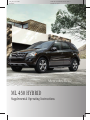
1
164_ZA; 2; 2, en-US
d2ureepe,
2009-05-12T15:08:04+02:00 - Seite 1
Version: 2.11.8.1
ML 450 HYBRID
Supplemental Operating Instructions
164_ZA; 2; 2, en-US
d2ureepe,
Symbols
Trademarks®:
RESP® is a registered trademark of Daimler.
The following symbols are found in this
Supplemental Operating Instructions:
G Warning!
Warning notices draw your attention to
hazards that may endanger your health or life,
or the health or life of others.
! Highlights hazards that may result in
damage to your vehicle.
i Helpful hints or further information you
may find useful.
X
This symbol points to instructions
for you to follow.
A number of these symbols
X
appearing in succession indicates
a multiple-step procedure.
Y page This symbol tells you where to look
for further information on a topic.
This continuation symbol marks a
YY
warning or procedure which is
continued on the next page.
Display Text in displays, such as the control
system, are printed in the type
shown here.
2009-05-12T15:08:04+02:00 - Seite 2
Version: 2.11.8.1
164_ZA; 2; 2, en-US
d2ureepe,
2009-05-12T15:08:04+02:00 - Seite 1
Version: 2.11.8.1
Our company and staff congratulate you on
the purchase of your new Mercedes-Benz.
Your selection of our product is a
demonstration of your trust in our company
name. Furthermore, it exemplifies your desire
to own an automobile that will be as easy as
possible to operate and provide years of
service.
Your Mercedes-Benz represents the efforts of
many skilled engineers and craftsmen. To
help assure your driving pleasure, and also
the safety of you and your passengers, we ask
you to make a small investment of time:
RPlease
read this manual carefully, then
return it to your vehicle where it will be
handy for your reference.
RPlease
follow the recommendations
contained in this manual. They are
designed to acquaint you with the
operation of your Mercedes-Benz.
RPlease
pay attention to the warnings and
cautions contained in this manual. They are
designed to help improve the safety of the
vehicle operator and occupants.
We extend our best wishes for many miles of
safe, pleasurable driving.
Mercedes-Benz USA, LLC
A Daimler Company
1645845583 É1645845583BËÍ
164_ZA; 2; 2, en-US
d2ureepe,
2009-05-12T15:08:04+02:00 - Seite 2
Version: 2.11.8.1
164_ZA; 2; 2, en-US
d2ureepe,
2009-05-12T15:08:04+02:00 - Seite 3
Version: 2.11.8.1
Contents
Index ....................................................... 4
Introduction ........................................... 7
Safety and security ............................... 8
Controls in detail ................................. 11
Operation ............................................. 20
Practical hints ..................................... 24
Technical data ..................................... 36
3
164_ZA; 2; 2, en-US
d2ureepe,
4
2009-05-12T15:08:04+02:00 - Seite 4
Version: 2.11.8.1
Index
A
ABS (Antilock Brake System) ............... 9
Warning lamp ............................. 13, 29
Anticorrosion/antifreeze .................... 39
Antilock Brake System
see ABS
Automatic shift program .................... 18
Automatic transmission
Automatic shift program .................. 18
Messages in the multifunction
display ............................................. 25
Program mode
indicator .................................... 13, 19
Program mode selector switch
(automatic shift program) ................ 18
Axle oils ................................................ 38
B
BAS (Brake Assist System) ................... 9
Battery
Charging .......................................... 32
Charging condition high-voltage
battery (COMAND) ........................... 14
Jump starting ................................... 33
Messages in the multifunction
display ............................................. 26
Safety notes ..................................... 32
see High-voltage battery
Brake Assist System
see BAS
Brakes
Warning
lamp .......................................... 13, 29
Brake system
see RBS
C
Capacities and recommended
fuel/lubricants ....................................
Charging condition high-voltage
battery (COMAND) ...............................
COMAND
Charging condition high-voltage
battery .............................................
Fuel consumption ............................
38
14
Generated electric power ................
Overview ..........................................
Combustion engine
Malfunction ......................................
Starting ............................................
Consumption statistics (COMAND) . . .
Control system
Overview ..........................................
Coolant
Anticorrosion/antifreeze .................
Capacities ........................................
Cruise control ......................................
15
13
30
16
15
13
39
38
10
D
Displays
Charging condition high-voltage
battery (COMAND) ........................... 14
Messages in the multifunction
display ............................................. 24
Driving and parking
Safety notes ..................................... 16
Driving off ............................................ 17
Driving safety systems
ABS .................................................... 9
BAS .................................................... 9
RBS .................................................... 9
Driving systems
Cruise control .................................. 10
Driving tips .......................................... 17
E
Engine ............................................. 16, 30
Malfunction indicator
lamp ................................................. 13
see Combustion engine
Engine oil
Adding ............................................. 22
Checking level ................................. 21
Enviromental protection ....................... 7
ESP® (Electronic Stability Program)
Warning lamp ............................. 13, 29
F
14
15
Fluids
Automatic transmission fluid ........... 38
Brake fluid ....................................... 38
164_ZA; 2; 2, en-US
d2ureepe,
2009-05-12T15:08:04+02:00 - Seite 5
Version: 2.11.8.1
Index
Capacities ........................................
Engine coolant .................................
Engine oil .........................................
Power steering fluid .........................
Washer and headlamp cleaning
system .............................................
Front axle oil ........................................
Fuel .......................................................
Capacity, fuel tank ...........................
Fuel filler flap and cap ......................
Premium unleaded gasoline .............
Fuel filler flap .......................................
Opening manually ............................
Unlocking .........................................
Fuel filler flap switch ..........................
Fuels, coolants, lubricants etc.
Capacities ........................................
Fuel tank
Capacity ...........................................
Fuel filler flap and cap ......................
38
38
38
38
Jump starting ....................................... 33
L
39
38
20
38
21
38
21
31
20
20
Lamp
see Lamps, indicator and warning
Lamps, indicator and warning ............ 29
ABS/ESP® ................................. 13, 29
Brakes
(red) ........................................... 13, 29
Instrument cluster ..................... 13, 29
RBS ............................................ 13, 29
38
Message
see Lamps, indicator and warning
Motor Octane Number
see MON
Multifunction display
Symbol messages ............................ 26
Text messages ................................. 25
Vehicle status messages ................. 24
Multifunction display messages
Automatic transmission ................... 25
Battery ....................................... 26, 28
Display malfunction ......................... 24
Gas cap ............................................ 27
Power steering ................................. 27
38
21
G
Gasoline
see Fuel
H
High voltage
see Safety notes
High-voltage battery ............................. 8
Charging condition (COMAND) ........ 14
Exhaustive discharge ....................... 32
Messages in the multifunction
display ............................................. 26
HYBRID system
Automatic switch-off .................... 8, 31
Overview .......................................... 12
READY indicator ......................... 13, 16
I
Indicator and warning lamp
SRS ..................................................
Indicator lamp
see Lamps, indicator and warning
Instrument cluster ..............................
Lamps ..............................................
Introduction .........................................
J
31
13
29
11
M
O
Oil level
see Engine oil, Checking level
Operating safety .................................... 7
P
Parking ................................................. 18
Power gauge .................................. 13, 14
Power steering
Messages in the multifunction
display ............................................. 27
Program mode selector switch
Automatic shift program .................. 18
5
164_ZA; 2; 2, en-US
d2ureepe,
6
2009-05-12T15:08:04+02:00 - Seite 6
Version: 2.11.8.1
Index
R
V
RBS (Recuperative Brake
System) ............................................ 9, 11
Malfunction ................................ 29, 30
Warning lamp ............................. 13, 29
READY indicator ............................ 13, 16
Rear axle oil ......................................... 38
Recuperation statistics (COMAND) . . . 15
Refueling .............................................. 20
Research Octane Number
see RON
Rims ...................................................... 37
Risk of fire
see Safety notes
S
Safety
see Operating safety
Safety notes ........................................... 8
Silent-Start mode ................................ 16
SRS (Supplemental Restraint System)
Warning lamp ................................... 31
Starting
see Combustion engine
Submenu
Resetting values (COMAND) ............ 16
T
Technical data
Capacities fuels, coolants,
lubricants etc. ..................................
Coolant ............................................
Engine oils .......................................
Rims and tires ..................................
Vehicle specification ML 450
HYBRID ............................................
Washer and headlamp cleaning
system .............................................
Tires ......................................................
38
39
39
37
36
39
37
U
Unlocking
Fuel filler flap ................................... 20
Vehicle
Disuse .............................................. 32
Vehicle fire
see Safety notes
Vehicle modifications ........................... 7
Vehicle specification
ML 450 HYBRID ............................... 36
W
Warning labels ....................................... 8
Wheels, sizes ....................................... 37
Winter tires .......................................... 37
164_ZA; 2; 2, en-US
d2ureepe,
2009-05-12T15:08:04+02:00 - Seite 7
Version: 2.11.8.1
Introduction
Enviromental protection
Have the high-voltage battery disposed of in
an environment-friendly manner by an
authorized Mercedes-Benz Center.
G Warning!
The HYBRID system is energized by high
voltage. The components of the HYBRID
system are indicated by yellow warning
labels. High-voltage cables are orangecolored.
You could be seriously or even fatally injured
when you
Rtamper
with components or high-voltage
cables of the HYBRID system
Rtouch
components or high-voltage cables
of the HYBRID system after the vehicle has
been involved in an accident
Rtouch damaged components of the HYBRID
system
Do not remove the high-voltage battery of the
HYBRID system. Have the high-voltage
battery disposed of in an environmentfriendly manner by an authorized MercedesBenz Center.
Operating safety
G Warning!
When your vehicle is in electric drive mode the
engine produces significantly lower noise
levels. Other motorists or pedestriants,
especially those who are visually or hearing
impaired, may be unable to hear your vehicle
while it is in motion. This is particularly true
when driving at lower speeds and during
parking maneuvers. At all times, it is the
responsibility of the driver to be aware of their
surroundings, especially in these low speed
situtations. Otherwise other road users could
be seriously or fatally injured.
G Warning!
Have all work on the vehicle, especially safetyrelated work, work on safety-relevant
systems, work on the HYBRID system as well
as maintenance work, carried out by an
authorized Mercedes-Benz Center.
i For more information on operating safety,
refer to the Operator’s Manual.
Vehicle modifications
G Warning!
Improper work on the HYBRID system or
modifications of the vehicle can cause vehicle
systems to cease functioning properly. You
could lose control over the vehicle and cause
an accident.
Therefore, have work on the HYBRID system
and modifications of the vehicle such as
installation or modification of vehicle
equipment carried out by an authorized
Mercedes-Benz Center
i For more information on operating safety,
refer to the Operator’s Manual.
Proper use of the vehicle
Proper use of the vehicle requires that you are
familiar with the following information and
rules:
Rthe
safety precautions in this manual
Rthe “Technical data” section in this manual
Rthe
Operator's Manual
Rtraffic
rules and regulations
Rmotor
vehicle laws and safety standards
Z
7
164_ZA; 2; 2, en-US
d2ureepe,
8
2009-05-12T15:08:04+02:00 - Seite 8
Version: 2.11.8.1
Safety and security
Safety notes
Warning labels
label. Do not tamper with any components or
with the orange high-voltage cables of the
HYBRID system.
G Warning!
Various warning labels are attached to your
vehicle. These warning labels are intended to
make you and others aware of various risks.
Do not remove any of these warning labels
unless explicitly instructed to do so by
information on the label itself. Removing
warning labels may cause you and others to
be unaware of certain risks which may result
in an accident and/or personal injury.
Danger of electric shock
The components of the HYBRID system are
indicated by yellow warning labels to make
you aware of high voltage. High-voltage
cables are orange-colored.
Engine compartment
Before opening the hood do the following:
X
Engage the parking brake.
Shift the automatic transmission into park
position P.
X Switch off the ignition.
The READY indicator (Y page 16) in the
instrument cluster goes out.
X Remove the SmartKey from the starter
switch or remove the SmartKey with
KEYLESS-GO from the vehicle.
X Observe the safety notes on the danger of
electric shock in this manual.
X Observe the safety notes regarding the
hood in the Operator’s Manual.
X
Automatic HYBRID system switch-off
The HYBRID system switches off
automatically if
Rthe
Supplemental Restraint System (SRS)
activates the restraint systems in an
accident
G Warning!
The HYBRID system is energized by high
voltage.
You could be seriously or even fatally injured
when you
Rtamper
with components or high-voltage
cables of the HYBRID system
Rtouch
components or high-voltage cables
of the HYBRID system after the vehicle has
been involved in an accident
Rtouch damaged components of the HYBRID
system
Do not remove covers of components of the
HYBRID system that carry the yellow warning
Ra
short circuit in the HYBRID system is
detected
Ra
plug connection of the HYBRID system is
disconnected
These measures help to prevent you from
coming into contact with high voltage.
High-voltage battery
G Warning!
The high-voltage battery of the HYBRID
system is located under the cargo
compartment. When the pressure inside the
high-voltage battery exceeds a certain value,
164_ZA; 2; 2, en-US
d2ureepe,
2009-05-12T15:08:04+02:00 - Seite 9
Version: 2.11.8.1
Safety and security
for example in case of a vehicle fire,
inflammable gas will escape via a duct. The
inflammable gas escapes to an area
underneath the vehicles cargo compartment.
This prevents the high-voltage battery from
exploding.
Stay away from this area of the vehicle.
Driving safety systems
ABS (Antilock Brake System)
Braking
When the ABS engages during braking, the
ABS/ESP® warning lamp d in the
instrument cluster (Y page 13) flashes. The
brake pedal will pulsate only in certain
situations, for example on a slippery road.
i For more information on the ABS, refer to
the Operator's Manual.
RBS (Recuperative Brake System)
The RBS controls braking by blending the
vehicles friction brakes with the hybrid
transmissions recuperative energy function.
The RBS system must perform a self-test
when the ignition is switched on.
X Make sure the automatic transmission is in
park position P.
X Switch on the ignition.
X Apply the brake pedal fully and release it.
The self-test of the RBS is completed.
During the self-test of the RBS, less brake
pedal pressure than usual is required and the
brake pedal travel is longer. When you release
the brake pedal, the brake pedal travel is as
usual again.
For more information on the RBS, see
(Y page 11).
G Warning!
If the RBS malfunctions, the yellow RBS
warning lamp é and/or the red brake
warning lamp $ (USA only) or J
(Canada only) in the instrument cluster comes
on. Read and observe the messages in the
multifunction display that may appear. Find
the subentry “Malfunction” of the entry “RBS
(Recuperative Brake System)” in the index of
this manual and follow the steps described in
that section.
G Warning!
If the RBS malfunctions, less brake pedal
pressure than usual may be required and the
brake pedal travel may be longer. The brake
system still functions with full effectiveness.
If required, you have to depress the brake
pedal further. Adapt your speed and driving
accordingly.
G Warning!
Have work on the RBS, e.g. brake pad
replacement, carried out by qualified
technicians only.
When working on the RBS, certain
precautions must be taken, e.g. when putting
the brake system back into service.
Contact an authorized Mercedes-Benz
Center. Service conducted by qualified
technicians is required particularly for safetyrelevant work and work on safety-relevant
systems such as the RBS.
i For more information on the braking
system and for driving instructions, refer to
the Operator’s Manual.
BAS (Brake Assist System)
If you apply the brakes very quickly, the RBS
provides full brake boost as fast as possible.
In doing so, less brake pedal pressure than
usual is required and the brake pedal travel is
longer.
X Apply continuous full braking pressure until
the emergency braking situation is over.
The ABS will prevent the wheels from
locking.
Z
9
164_ZA; 2; 2, en-US
d2ureepe,
10
Safety and security
i For more information on the BAS, refer to
the Operator’s Manual.
Driving systems
Cruise control
When the cruise control brakes the vehicle,
the brake pedal is not depressed.
i For more information on the cruise
control, refer to the Operator’s Manual.
2009-05-12T15:08:04+02:00 - Seite 10
Version: 2.11.8.1
164_ZA; 2; 2, en-US
d2ureepe,
2009-05-12T15:08:04+02:00 - Seite 11
Version: 2.11.8.1
Controls in detail
Introduction
The HYBRID technology combines an
economical combustion engine with a
powerful hybrid transmission. The HYBRID
system selects the most efficient operating
mode for each driving situation automatically.
You can drive the vehicle in the usual manner.
The HYBRID system turns the combustion
engine off as often as possible in order to save
fuel.
Depending on various conditions such as the
charging level of the high-voltage battery or
the operating temperature, the vehicle can
run on electrical energy alone. These
conditions as well as the degree to which the
driver accelerates determine the vehicle
speed and range that can be achieved for allelectrical driving.
Driving off and accelerating consumes the
most energy. Thus, the hybrid transmission
supports the combustion engine with the
energy stored in the high-voltage battery. The
energy is also used for electrical driving, for
operation of the electric compressor of the
cooling system and to support the 12-volt onboard power supply. The hybrid drive thereby
contributes significantly to the fuel economy
of your vehicle.
For information on driving with HYBRID, see
(Y page 16).
The current operating mode of the HYBRID
system can be displayed in the instrument
cluster (Y page 13) and in the COMAND
display (Y page 13).
The COMAND can also display a chart of the
fuel consumption and the electric power that
has been generated (Y page 15).
G Warning!
When the READY indicator in the instrument
cluster is on while the combustion engine is
off, the combustion engine has been turned
off automatically. All vehicle systems
continue to be active as long as the ignition is
switched on. When you open the driver’s door
and unbuckle the seat belt with the READY
indicator on, while the automatic
transmission is in position N or P, the
combustion engine starts automatically.
Therefore, always do the following before
leaving the vehicle:
REngage the parking brake.
RBS (Recuperative Brake System)
With the RBS activated (Y page 9), the hybrid
transmission functions as a generator when
coasting and braking. HYBRID converts the
energy of movement into electric power and
stores it in the high-voltage battery. The highvoltage battery does not require additional
charging by other means.
RShift
the automatic transmission into park
position P.
RSwitch off the ignition. The READY indicator
goes out.
Z
11
164_ZA; 2; 2, en-US
d2ureepe,
12
2009-05-12T15:08:04+02:00 - Seite 12
Version: 2.11.8.1
Controls in detail
Overview HYBRID system
Component
:
High-voltage battery
;
12-volt battery
=
Hybrid transmission
?
Voltage transformer
(transforms the voltage of the 12-volt
battery and the high-voltage battery in
both directions for best possible
power management)
Component
A
Power electronics
(control the high-voltage system)
B
Electric refrigerant compressor for
the climate control system
C
Combustion engine
164_ZA; 2; 2, en-US
d2ureepe,
2009-05-12T15:08:04+02:00 - Seite 13
Version: 2.11.8.1
Controls in detail
Instrument cluster
Function
:
Page
$ Brake warning lamp,
USA only
ABS/ESP®
29
;
d
lamp
=
J Brake warning lamp,
Canada only
29
Multifunction display
with:
Charging level high-voltage
battery
14
?
A
warning
9,
29
é Recuperative Brake
System (RBS) warning lamp
C
+ Supplemental
Restraint System (SRS)
indicator lamp
E
Power gauge
F
Multifunction display
with:
Automatic transmission
program mode indicator
READY indicator for the
HYBRID system
Page
14
18
16
Control system and COMAND
29
B
Function
31
; Engine malfunction
indicator lamp, Canada only
i For information on the instrument cluster
control system and COMAND operation,
refer to the Operator’s Manual.
The current operating mode of the HYBRID
system can be displayed in the multifunction
display and in the COMAND.
The COMAND can also display a chart of the
fuel consumption and the electric power that
has been generated (Y page 15).
21
D
! Engine malfunction
indicator lamp, USA only
21
Z
13
164_ZA; 2; 2, en-US
d2ureepe,
2009-05-12T15:08:04+02:00 - Seite 14
Version: 2.11.8.1
Controls in detail
14
Selecting submenu in the
multifunction display
COMAND display examples
Use the buttons on the multifunction steering
wheel.
X Press button V or U repeatedly until
the standard display appears.
X Press button & or * to select the
HYBRID menu.
Selecting submenu in the COMAND
display
X
Select System Q Hybrid Q Energy
Flow.
Example illustration: Operating mode display
1 Combustion engine
2 Hybrid transmission
3 High-voltage battery
4 Charging condition of high-voltage
battery in percent
5 Flow of energy
The HYBRID components that are currently
active are highlighted in the COMAND
display.
Multifunction display
Power gauge
COMAND display
Recuperation – the hybrid transmission functions as a generator, for example when
coasting or braking. The kinetic energy of the vehicle is converted into electric power and
stored in the high-voltage battery.
The multifunction display indicates charging of the high-voltage battery by an arrow pointing
upwards. The pointer of the power gauge moves into the charge section. The COMAND
display indicates the flow of energy by green arrows.
164_ZA; 2; 2, en-US
d2ureepe,
2009-05-12T15:08:04+02:00 - Seite 15
Version: 2.11.8.1
Controls in detail
Multifunction display
Power gauge
COMAND display
Boost effect – the hybrid transmission supports the combustion engine when driving off
and when accelerating.
The multifunction display indicates discharging of the high-voltage battery by an arrow
pointing downwards. The pointer of the power gauge moves into the boost section. The
COMAND display indicates the flow of energy by white or red arrows (depending on the
acceleration).
Multifunction display
Power gauge
COMAND display
Electric driving – the hybrid transmission powers the vehicle, up to a maximum speed of
30 mph (50 km/h).
The multifunction display indicates discharging of the high-voltage battery by an arrow
pointing downwards. The pointer of the power gauge moves within the range of its economy
section. The COMAND display indicates the flow of energy by green arrows.
i Maximum Hybrid battery life is ensured by
the electronic charge control maintaining a
charge level between 25 % and 80 %. This
is the ideal range for the Hybrid battery and
therefore the charge level displayed in the
instrument cluster or COMAND may not
approach 100 %. This is intentional and
does not indicate a malfunction of the
Hybrid battery or the charging
components.
Displaying fuel consumption and
generated electric power
The COMAND display indicates the fuel
consumption and the generated electric
power for the last 15 minutes of driving.
X Select System Q Hybrid Q
Consumption.
Z
15
164_ZA; 2; 2, en-US
d2ureepe,
16
2009-05-12T15:08:04+02:00 - Seite 16
Version: 2.11.8.1
Controls in detail
Keep the driver’s footwell clear of all
obstacles. If there are any floormats or
carpets in the footwell, make sure the pedals
still have sufficient clearance.
During sudden driving or braking maneuvers
the objects could get caught between or
under the pedals. You could then no longer
brake or accelerate. This could lead to
accidents and injury.
1 Fuel consumption
; Average fuel consumption From Start as
Starting the engine
shown in the multifunction display of the
instrument cluster in the Trip computer
menu.
= Generated electric power
Each bar in the chart represents the average
value for 1 minute.
Resetting values
The values are reset together when resetting
the trip computer in the From Start
submenu. Refer to the Operator’s Manual.
: READY indicator
X
Driving and parking
Safety notes
G Warning!
When your vehicle is in electric drive mode the
engine produces significantly lower noise
levels. Other motorists or pedestriants,
especially those who are visually or hearing
impaired, may be unable to hear your vehicle
while it is in motion. This is particularly true
when driving at lower speeds and during
parking maneuvers. At all times, it is the
responsibility of the driver to be aware of their
surroundings, especially in these low speed
situtations. Otherwise other road users could
be seriously or fatally injured.
G Warning!
Make sure absolutely no objects are
obstructing the pedals’ range of movement.
Switch on the ignition.
Apply the brake pedal fully and release it.
The self-test of the RBS is completed. For
more information on the RBS, see
(Y page 9).
X Observe the notes on “Starting the engine”
in the Operator’s Manual and start the
combustion engine.
X
Silent-Start mode
The combustion engine may not start each
time you start the vehicle with the SmartKey
or with KEYLESS-GO.
Depending on various conditions such as the
charging level of the high-voltage battery, you
may drive off with electrical energy alone. The
vehicle is then in Silent-Start mode. The
READY indicator : will then indicate that the
HYBRID systems are operational.
164_ZA; 2; 2, en-US
d2ureepe,
2009-05-12T15:08:04+02:00 - Seite 17
Version: 2.11.8.1
Controls in detail
G Warning!
When the READY indicator in the instrument
cluster is on while the combustion engine is
off, the combustion engine has been turned
off automatically. All vehicle systems
continue to be active as long as the ignition is
switched on. When you open the driver’s door
and unbuckle the seat belt with the READY
indicator on, while the automatic
transmission is in position N or P, the
combustion engine starts automatically.
Therefore, always do the following before
leaving the vehicle:
REngage the parking brake.
RShift
the automatic transmission into park
position P.
RSwitch off the ignition. The READY indicator
goes out.
The combustion engine turns off
automatically when the system determines
that it is not needed. The combustion engine
does not turn off automatically when
Rthe
operation strategy requires that the
combustion engine is running
Rthe
self-diagnosis of the combustion
engine management is still running
Rthe
combustion engine is running below or
above the operating temperature
Rthe catalytic converter is running below the
operating temperature
Rthe
vehicle is being driven up an extremely
steep incline
Rthe hybrid components are below or above
their operating temperature
Rthe accelerator pedal is being depressed to
hard
Rthe
vehicle speed is above 34 mph
(55 km/h)
Rthe
automatic transmission is
malfunctioning
Rthe
hood is open
Rthe
high-voltage battery is not charged
sufficiently
Driving off
G Warning!
When your vehicle is in electric drive mode the
engine produces significantly lower noise
levels. Other motorists or pedestriants,
especially those who are visually or hearing
impaired, may be unable to hear your vehicle
while it is in motion. This is particularly true
when driving at lower speeds and during
parking maneuvers. At all times, it is the
responsibility of the driver to be aware of their
surroundings, especially in these low speed
situtations. Otherwise other road users could
be seriously or fatally injured.
Depress the brake pedal and shift the
automatic transmission into drive position D
or reverse gear R. If the message Depress
brake to shift out of P. appears in the
multifunction display:
X Depress the brake pedal with somewhat
greater force and select the desired
transmission position.
i Read and observe messages that may
appear in the multifunction display
(Y page 24).
For more information on driving off, refer to
the Operator’s Manual.
Driving
Driving tips
RThink
ahead and keep sufficient distance.
RAvoid
frequent and rapid acceleration as
well as abrupt braking.
Z
17
164_ZA; 2; 2, en-US
d2ureepe,
18
2009-05-12T15:08:04+02:00 - Seite 18
Version: 2.11.8.1
Controls in detail
RThe
hybrid transmission supports the
combustion engine when driving off and
when accelerating.
RThe
hybrid transmission functions as a
generator when coasting the vehicle with
the automatic transmission in drive
position D and during braking.
i For additional general driving
instructions, refer to the Operator’s
Manual.
Parking
G Warning!
When your vehicle is in electric drive mode the
engine produces significantly lower noise
levels. Other motorists or pedestriants,
especially those who are visually or hearing
impaired, may be unable to hear your vehicle
while it is in motion. This is particularly true
when driving at lower speeds and during
parking maneuvers. At all times, it is the
responsibility of the driver to be aware of their
surroundings, especially in these low speed
situtations. Otherwise other road users could
be seriously or fatally injured.
REngage
the parking brake.
RShift
the automatic transmission into park
position P.
RSwitch off the ignition. The READY indicator
goes out.
X
Engage the parking brake.
The parking brake indicator lamp $
(USA only) or ! (Canada only) in the
instrument cluster comes on.
X Shift the automatic transmission into park
position P.
X Switch off the ignition.
The READY indicator goes out.
i For more information on parking and on
turning off the combustion engine, refer to
the Operator’s Manual.
Automatic transmission
Automatic shift program
G Warning!
When the READY indicator in the instrument
cluster is on while the combustion engine is
off, the combustion engine has been turned
off automatically. All vehicle systems
continue to be active as long as the ignition is
switched on. When you open the driver’s door
and unbuckle the seat belt with the READY
indicator on, while the automatic
transmission is in position N or P, the
combustion engine starts automatically.
Therefore, always do the following before
leaving the vehicle:
Program mode selector switch
E Economy
For fuel-efficient
operation
S Sport
For sporty driving
164_ZA; 2; 2, en-US
d2ureepe,
2009-05-12T15:08:04+02:00 - Seite 19
Version: 2.11.8.1
Controls in detail
The current program mode appears in the
multifunction display.
: Program mode indicator
i The automatic program mode E, for fuel-
efficient driving, is active each time you
start the vehicle with the SmartKey or with
KEYLESS-GO.
X
Press the program mode selector switch
repeatedly until the letter of the desired
program mode appears in the multifunction
display.
Selecting program mode E means:
Renabling
electric driving with the hybrid
transmission whenever possible
Rconsumption-optimized
driving
characteristics considering the individual
driving style
Rmaximum
driving comfort by smooth gear
changes
Rcontinuous
power transmission
Selecting program mode S means:
Renabling
more electric driving as it is
possible with selected program mode E
Rsporty
engine and transmission setting
Rgear changes according to the driving style
and road conditions
Rdriving
characteristics of a conventional
eight-speed transmission
i For more information on the automatic
transmission, refer to the Operator’s
Manual.
Z
19
164_ZA; 2; 2, en-US
d2ureepe,
20
2009-05-12T15:08:04+02:00 - Seite 20
Version: 2.11.8.1
Operation
Otherwise, excessive unburned fuel may
reach the catalytic converter, causing it to
overheat and potentially start a fire.
Refueling
G Warning!
Gasoline is highly flammable and poisonous.
It burns violently and can cause serious
personal injury.
Never allow sparks, flames or smoking
materials near gasoline!
Turn off the engine before refueling.
Whenever you are around gasoline, avoid
inhaling fumes and any skin or clothing
contact. Extinguish all smoking materials.
Direct skin contact with fuels and the
inhalation of fuel vapors are damaging your
health.
G Warning!
Overfilling of the fuel tank may create
pressure in the system which could cause a
gas discharge. This could cause the gas to
spray back out when removing the fuel pump
nozzle, which could cause personal injury.
! Never refuel vehicles with gasoline engine
with diesel fuel. Even small amounts of
diesel fuel will damage the fuel system and
engine. Damage resulting from the use of
non-approved fuels or fuel additives or
resulting from mixing gasoline with diesel
fuel is not covered by the Mercedes-Benz
Limited Warranty.
i Only use premium unleaded gasoline with
a minimum Posted Octane Rating of 91
(average of 96 RON/86 MON).
Information on gasoline quality can
normally be found on the fuel pump. Please
contact gas station personnel in case
labels on the pump cannot be found.
For more information on gasoline, see
Operator's Manual, contact an authorized
Mercedes-Benz Center, or visit
www.mbusa.com (USA only).
X
Bring the vehicle to a standstill.
Engage the parking brake.
X Shift the automatic transmission into park
position P.
X Switch off the ignition.
The READY indicator (Y page 16) in the
instrument cluster goes out.
X Remove the SmartKey from the starter
switch or remove the SmartKey with
KEYLESS-GO from the vehicle.
X
i Before refueling your vehicle its fuel tank
system needs to be depressurized.
! If you have accidentally filled the tank
with incorrect or non-approved fuel, do not
switch on the ignition. Otherwise the
incorrect or non-approved fuel will get into
the fuel lines. The fuel system must be
drained completely. Contact an authorized
Mercedes-Benz Center to have the fuel
system drained completely.
! To prevent damage to the catalytic
converters, only use premium unleaded
gasoline in this vehicle.
Any noticeable irregularities in engine
operation should be repaired promptly.
X
Press fuel filler flap switch :.
Indicator lamp ; comes on as the fuel filler
flap is unlocked.
164_ZA; 2; 2, en-US
d2ureepe,
2009-05-12T15:08:04+02:00 - Seite 21
Version: 2.11.8.1
Operation
In case of a blinking indicator lamp ;,
pressure on the fuel tank system needs to be
released first.
A malfunction in the system has been
detected if
Rthe indicator lamp ; fails to stop blinking
after approximately 10 seconds after the
fuel filler flap switch : has been pressed
Rthe
indicator lamp ; does not come on at
all
Rthe
malfunction indicator lamp ! (USA
only) or ; (Canada only) comes on
The fuel filler flap is located on the right-hand
side of the vehicle towards the rear.
i In case the fuel filler flap switch does not
release the fuel filler flap, see “Opening the
fuel filler flap manually” (Y page 31).
G Warning!
Remove fuel filler cap slowly. Fuel spray may
cause injury.
Complete refueling within 20 minutes after
opening the fuel filler flap. Otherwise fuel may
spray out and cause injury. If the refueling
process cannot be completed within
20 minutes, press the fuel filler flap switch
again.
i Leaving the combustion engine running
and the fuel filler cap open can cause the
yellow fuel tank reserve warning lamp to
flash and the malfunction indicator
lamp ! (USA only) or ; (Canada
only) to illuminate.
For more information on refueling, see
Operator's Manual.
X
Opening: Pull fuel filler flap = out in
direction of arrow.
X Turn fuel filler cap ? counterclockwise.
X Take off fuel filler cap ?.
! The fuel filler cap is tethered to the fuel
filler neck. Do not drop the cap. It could
damage the vehicle paint finish.
X
Set fuel filler cap ? on fuel filler flap =.
Fully insert filler nozzle unit and refuel.
X Only fill your tank until the filler nozzle unit
cuts out – do not top off or overfill.
X
X
Closing: Turn fuel filler cap ? until it
audibly engages.
X Close fuel filler flap =.
The fuel filler flap is locked.
The indicator lamp on the fuel filler flap
switch goes out (Y page 20).
Engine oil
The amount of oil your combustion engine
consumes will depend on a number of factors,
including driving style. Increased oil
consumption can occur when the vehicle is
new or the vehicle is driven frequently at
higher engine speeds.
Engine oil consumption checks should only
be made after the vehicle break-in period.
! Do not use any special lubricant additives,
as these may damage the drive assemblies.
Z
21
164_ZA; 2; 2, en-US
d2ureepe,
2009-05-12T15:08:04+02:00 - Seite 22
Version: 2.11.8.1
Operation
22
Using special additives not approved by
Mercedes-Benz may cause damage not
covered by the Mercedes-Benz Limited
Warranty.
For further information contact an
authorized Mercedes-Benz Center.
Notes on checking engine oil level
When checking the oil level the vehicle must
be parked on level ground and the vehicle
must have been stationary for at least
5 minutes with the combustion engine turned
off.
Checking engine oil level
Before opening the hood do the following:
X
Engage the parking brake.
Shift the automatic transmission into park
position P.
X Switch off the ignition.
The READY indicator (Y page 16) in the
instrument cluster goes out.
X Remove the SmartKey from the starter
switch or remove the SmartKey with
KEYLESS-GO from the vehicle.
X Observe the safety notes on the danger of
electric shock in this manual.
X Open the hood, see Operator's Manual.
X
X
Pull out oil dipstick ;.
X Wipe oil dipstick ; clean.
X Fully insert oil dipstick ; into the dipstick
guide tube.
X Pull out oil dipstick ; again after
approximately 3 seconds to obtain
accurate reading.
The oil level is correct when it is between
lower (min) mark ? and upper (max) mark
= of oil dipstick ;.
i The filling quantity between the upper and
lower marks on the oil dipstick is
approximately 2.1 US qt. (2.0 l).
X
If necessary, add engine oil (Y page 22).
Install cover :.
For more information on engine oil, see
Operator's Manual.
X
Adding engine oil
X
Remove cover : by pulling it in direction
of arrow.
164_ZA; 2; 2, en-US
d2ureepe,
2009-05-12T15:08:04+02:00 - Seite 23
Version: 2.11.8.1
Operation
X
Remove the cover (Y page 22).
X Unscrew filler cap : from filler neck.
X Add engine oil as required. Be careful not
to overfill with oil.
Be careful not to spill any oil when adding.
Avoid environmental damage caused by oil
entering the ground or water.
! Excess oil must be siphoned or drained
off. It could cause damage to the engine
and emission control system not covered
by the Mercedes-Benz Limited Warranty.
X
X
Screw filler cap : back on filler neck.
Install the cover (Y page 22).
Z
23
164_ZA; 2; 2, en-US
d2ureepe,
24
2009-05-12T15:08:04+02:00 - Seite 24
Version: 2.11.8.1
Practical hints
Vehicle status messages in the
multifunction display
Notes
Warning and malfunction messages appear in
the multifunction display located in the
instrument cluster.
Certain warning and malfunction messages
are accompanied by an audible signal.
Address these messages accordingly and
follow the additional instructions given in this
Supplemental Operating Instructions
Booklet.
Selecting the Vehicle status message
memory menu in the control system displays
both cleared and uncleared messages.
High-priority messages appear in the
multifunction display in red color.
Certain messages of high priority cannot be
cleared from the multifunction display using
the reset button or button &, *,
U or V on the multifunction steering
wheel.
Other messages of high priority and
messages of less immediate priority can be
cleared from the multifunction display using
the reset button or button &, *,
U or V on the multifunction steering
wheel. They are then stored in the Vehicle
status message memory menu. Remember
that clearing a message will only make the
message disappear. Clearing a message will
not correct the condition that caused the
message to appear.
G Warning!
All categories of messages contain important
information which should be taken note of
and, where a malfunction is indicated,
addressed as soon as possible at an
authorized Mercedes-Benz Center.
Failure to repair the condition noted may
cause damage not covered by the MercedesBenz Limited Warranty, or result in property
damage or personal injury.
G Warning!
No messages will be displayed if either the
instrument cluster or the multifunction
display is inoperative.
As a result, you will not be able to see
information about your driving conditions,
such as
Rspeed
Routside
temperature
Rwarning/indicator
lamps
Rmalfunction/warning
Rfailure
messages
of any systems
Driving characteristics may be impaired.
If you must continue to drive, do so with added
caution. Contact an authorized MercedesBenz Center as soon as possible.
On the pages that follow, you will find a
compilation of the warning and malfunction
messages specific to the HYBRID system. For
all other warning and malfunction messages,
refer to the Operator’s Manual.
164_ZA; 2; 2, en-US
d2ureepe,
2009-05-12T15:08:04+02:00 - Seite 25
Version: 2.11.8.1
Practical hints
Text messages
Display messages
Possible causes/consequences and X Solutions
Driving
in
Reverse
currently
not
possible
Driving in reverse is currently not possible. The hybrid
transmission is overheated.
X Wait briefly.
X Depress the brake pedal.
X Release the accelerator pedal.
X The message in the multifunction disappears.
Wait
briefly
Driving
in
Reverse
now
possible
again
Depress
brake
The hybrid transmission has cooled down.
X Driving in reverse is now possible again.
to shift
out of P.
You have attempted to shift the automatic transmission into
drive position D, reverse gear R or neutral position N without
depressing the brake pedal or without depressing it fully.
X Depress the brake pedal fully.
Engine
Can Now
Be Started
The high-voltage battery has been charged via the voltage
transformer automatically.
X Start the combustion engine.
X Disconnect the charge unit or jumper cables.
X Drive the vehicle for some time in order to charge the 12volt battery and the high-voltage battery.
Fuel
Filler
Flap Open
The fuel filler flap is open.
X Check the fuel filler flap.
X If it is not closed properly: Close the fuel filler flap.
X If it is closed properly: Have the fuel system checked by
an authorized Mercedes-Benz Center.
Z
25
164_ZA; 2; 2, en-US
d2ureepe,
26
2009-05-12T15:08:04+02:00 - Seite 26
Version: 2.11.8.1
Practical hints
Symbol messages
Display messages
Possible causes/consequences and X Solutions
c
Charging
Hybrid
Battery
Please
Wait
d
Malfunctio The HYBRID system is malfunctioning.
n
X Have the system checked at an authorized Mercedes-Benz
Center.
d
Stop car,
switch
engine
off.
c
Malfunctio The high-voltage system is malfunctioning. In addition an
acoustic warning sounds.
n
X Contact an authorized Mercedes-Benz Center immediately.
The high-voltage battery is discharged. You have switched on
the ignition while the 12-volt battery was being charged with
an approved charge unit or while jump starting the vehicle.
The high-voltage battery is being charged via the voltage
transformer automatically. Depending on the state of the
high-voltage battery's discharge, the charging procedure may
take up to 60 minutes. The message Engine Can Now Be
Started appears in the multifunction display, after the
system became adequately charged to start the combustion
engine (Y page 25).
If the display message Engine Can Now Be Started does
not appear after about an hour:
X Try to start the combustion engine.
X If the combustion engine cannot be started: Contact an
authorized Mercedes-Benz Center.
The HYBRID system is malfunctioning. In addition an acoustic
warning sounds.
X Stop the vehicle in a safe location as soon as possible.
X Engage the parking brake.
X Switch off the ignition.
X Wait at least 60 seconds for the system to complete the
necessary check cycles before you start the combustion
engine again.
X If the combustion engine cannot be started again contact
an authorized Mercedes-Benz Center.
164_ZA; 2; 2, en-US
d2ureepe,
2009-05-12T15:08:04+02:00 - Seite 27
Version: 2.11.8.1
Practical hints
Display messages
c
Possible causes/consequences and X Solutions
Malfunctio The high-voltage system is malfunctioning. In addition an
n Service acoustic warning sounds.
Required
X Drive with added caution to the nearest authorized
Mercedes-Benz Center.
The combustion engine cannot be started again, if
Rthe
automatic transmission is set to position neutral
position N or park position P
Rthe
hood is opened
Rthe
bolted cover in the trunk is removed
8
Gas Cap
Open
A loss of pressure has been detected in the fuel system. The
fuel cap may not be closed properly or the fuel system may
be leaking.
X Check the fuel cap.
X If it is not closed properly: Close the fuel cap.
X If it is closed properly: Have the fuel system checked by
an authorized Mercedes-Benz Center.
D
Power
Steering
Malfunctio
n
See
Operator's
Manual
Power assistance for the steering system is not available. A
considerably higher degree of effort is necessary to steer the
vehicle.
X Check whether you are capable to apply the higher degree
of effort necessary to safely steer the vehicle.
If you are able to steer the vehicle safely:
X
X
Continue driving with added caution.
Have the system checked at an authorized Mercedes-Benz
Center.
If, in any way, you feel that you are not able to steer the vehicle
safely:
X
Stop the vehicle in a safe location as soon as it is safe to
do so.
X Apply the parking brake.
X Do not continue to drive.
X Contact an authorized Mercedes-Benz Center.
Z
27
164_ZA; 2; 2, en-US
d2ureepe,
28
2009-05-12T15:08:04+02:00 - Seite 28
Version: 2.11.8.1
Practical hints
Display messages
Possible causes/consequences and X Solutions
#
The 12-volt battery is no longer charging.
Possible causes:
Rvoltage
Rthe
X
transformer malfunctioning
12-volt battery is malfunctioning
Stop the vehicle in a safe location or as soon as it is safe
to do so.
X Engage the parking brake.
X Do not continue to drive.
X Contact an authorized Mercedes-Benz Center.
164_ZA; 2; 2, en-US
d2ureepe,
2009-05-12T15:08:04+02:00 - Seite 29
Version: 2.11.8.1
Practical hints
What to do if ...
Lamps in instrument cluster
Problem
Possible causes/consequences and X Solutions
é
The RBS is malfunctioning.
The yellow RBS
Risk of accident!
(Recuperative Brake
The combustion engine may not turn off automatically.
System) warning lamp
X Read and observe messages that may appear in the
is on while the
multifunction display (Y page 24).
combustion engine is
X
Continue driving with added caution.
running. In addition, an
acoustic warning may X Contact an authorized Mercedes-Benz Center.
sound.
$
(USA only)
J
(Canada only)
The red brake warning
lamp is on while the
combustion engine is
running. An additional
acoustic warning
sounds.
The RBS is malfunctioning.
Risk of accident!
Brake pedal travel may be longer than usual and the braking
behavior of the vehicle may change.
X Stop the vehicle in a safe location or as soon as it is safe to do
so. Do not continue to drive.
X Contact an authorized Mercedes-Benz Center immediately.
X Read and observe messages that may appear in the
multifunction display (Y page 24), see Operator’s Manual.
The brake fluid level in the brake fluid reservoir is too low.
Risk of accident!
X Stop the vehicle in a safe location or as soon as it is safe to do
so. Do not continue to drive.
X Contact an authorized Mercedes-Benz Center immediately.
X Read and observe messages that may appear in the
multifunction display (Y page 24), see Operator’s Manual.
Do not add brake fluid. This will not solve the problem.
d
The yellow ABS/ESP®
warning lamp flashes
while driving.
The ESP®, the 4-ETS, or the ABS has come into operation because
of detected traction loss for at least one wheel.
Risk of accident!
The cruise control is deactivated.
X When driving off, apply as little throttle as possible.
X While driving, ease up on the accelerator pedal.
X Adapt your speed and driving to the prevailing road and weather
conditions.
X Do not switch off the ESP®.
Exceptions, see Operator’s Manual.
Z
29
164_ZA; 2; 2, en-US
d2ureepe,
30
2009-05-12T15:08:04+02:00 - Seite 30
Version: 2.11.8.1
Practical hints
Problem
Possible causes/consequences and X Solutions
The warning and
indicator lamps in the
instrument cluster fail
to come on when
switching on the
ignition.
The 12-volt battery and/or the high-voltage battery are
discharged.
X Charge the 12-volt battery (Y page 32).
or
X Get a jump start (Y page 33).
or
X Contact an authorized Mercedes-Benz Center.
Combustion engine
Problem
Possible causes/consequences and X Solutions
The combustion engine
cannot be started. The
warning and indicator
lamps in the instrument
cluster come on when
switching the ignition.
The high-voltage battery is discharged.
The discharged high-voltage battery is being charged with the
ignition switched on while the vehicle is being jump started
(Y page 33).
X Read and observe messages that may appear in the
multifunction display (Y page 24).
The combustion engine The self-diagnosis has not been completed yet or the HYBRID
cannot be started. The system is malfunctioning.
multifunction display
X Switch off the ignition and switch it back on.
does not display any
X Try to start the combustion engine once more.
messages.
X If the combustion engine cannot be started: Contact an
authorized Mercedes-Benz Center.
RBS (Recuperative Brake System)
Problem
Possible causes/consequences and X Solutions
Less brake pedal
pressure is required
and the brake pedal
travel is longer than
usual.
X
Apply the brake pedal fully and release it.
The required brake pedal pressure and the brake pedal travel
are back to normal.
The RBS is malfunctioning.
Risk of accident!
X Read and observe the messages in the multifunction display
(Y page 24) and the notes on warning and indicator lamps in the
instrument cluster (Y page 29).
164_ZA; 2; 2, en-US
d2ureepe,
2009-05-12T15:08:04+02:00 - Seite 31
Version: 2.11.8.1
Practical hints
Problem
Possible causes/consequences and X Solutions
The brake pedal
pulsates.
The RBS is providing electronic controlled brake boost. Read and
observe the notes on the ABS/ESP® warning lamp (Y page 9).
The HYBRID system switches of automatically
Problem
Possible causes/consequences and X Solutions
The HYBRID system
has switched of
automatically.
Your vehicle was involved in an accident.
The HYBRID system remains switched off, if
Rthe
combustion engine cannot be started again after a few
seconds
Rthe SRS warning lamp + in the instrument cluster comes on
X
The HYBRID system
has switched of
automatically. An
additional message
appears in the
multifunction display.
Contact an authorized Mercedes-Benz Center.
A short circuit in the HYBRID system has occurred or a plug
connection of the HYBRID system was disconnected.
X Read and observe messages that may appear in the
multifunction display (Y page 24).
X Contact an authorized Mercedes-Benz Center.
Opening the fuel filler flap manually
G Warning!
Avoid contact with the vehicle walls as they
may contain sharp edges. Otherwise, you
could injure yourself while opening the fuel
filler flap.
G Warning!
Open the fuel filler flap manually only if the
fuel filler flap switch is not operational.
With the fuel filler flap opened manually, fuel
may spray out during the refueling process.
In case the fuel filler flap switch (Y page 20)
does not release the fuel filler flap, you can
open it manually.
The fuel filler flap release is located behind a
cover on the passenger side in the cargo
compartment.
X
Open the tailgate, see Operator's Manual.
Insert a suitable object such as a coin into
the slot of locks :.
X Turn locks : by 90° in direction of the
arrows.
X Remove cover ;.
X
Z
31
164_ZA; 2; 2, en-US
d2ureepe,
2009-05-12T15:08:04+02:00 - Seite 32
Version: 2.11.8.1
Practical hints
32
! Deep discharge caused by prolonged
X
Pull light-blue fuel filler flap release = in
direction of arrow.
The fuel filler flap is unlocked.
X Open the fuel filler flap (Y page 21).
X Close cover ;.
X Close the tailgate.
Battery
Notes
Your vehicle is equipped with a 12-volt
battery and a high-voltage battery. The highvoltage battery stores the power required for
the hybrid transmission. The hybrid
transmission also starts the combustion
engine.
Have any work on the batteries performed at
an authorized Mercedes-Benz Center.
i Read and observe the safety notes
(Y page 8) and the notes on the 12-volt
battery in the Operator’s Manual.
G Warning!
The electrolyte, i.e. the battery fluid, is toxic
and caustic. Do not allow this fluid to come in
contact with eyes, skin or clothing, for
example in case of an accident.
In case it does, immediately flush affected
area with water and seek medical help
immediately.
For information on the location of the 12-volt
battery and the high-voltage battery, see
(Y page 12).
periods of the vehicle not being used, can
damage the high-voltage battery.
During such periods, operate the vehicle
every 4 weeks for several minutes in order
to charge the high-voltage battery.
During the charging process, switch off
electrical consumers that are currently not
needed, e.g. climate control system or seat
heating.
If necessary, get a jump start.
G Warning!
Inhalation of exhaust gas is hazardous to your
health. All exhaust gas contains carbon
monoxide (CO), and inhaling it can cause
unconsciousness and lead to death. Do not
run the engine in confined areas (such as a
garage) which are not properly ventilated.
If you do not intend to operate your vehicle
for an extended period of time, contact an
authorized Mercedes-Benz Center about
steps you need to observe.
Charging the battery
Charging the 12-volt battery
G Warning!
Never charge a battery while still installed in
the vehicle unless the accessory battery
charge unit approved by Mercedes-Benz is
being used. Gases may escape during
charging and could cause an explosion that
may result in personal injury, paint damage or
corrosion.
An accessory battery charge unit specially
adapted for Mercedes-Benz vehicles and
tested and approved by Mercedes-Benz is
available. It permits the charging of the
battery in its installed position. Contact an
authorized Mercedes-Benz Center for
information and availability.
164_ZA; 2; 2, en-US
d2ureepe,
2009-05-12T15:08:04+02:00 - Seite 33
Version: 2.11.8.1
Practical hints
Charge battery in accordance with the
separate instructions for the accessory
battery charger.
X
X
Open the hood, see Operators' Manual.
Follow the instructions in the separate
operating instructions of the charge unit.
Observe the following:
RJump
starting should only be performed
when the combustion engine and the
catalytic converter are cold.
RDo
not jump start if the battery is frozen.
Let the battery thaw out first.
ROnly
jump start from batteries with the
same voltage rating (12 V). Jump starting
with a more powerful battery could damage
the vehicle’s electrical system, which is not
covered by the Mercedes-Benz Limited
Warranty.
ROnly
use jumper cables with sufficient
cross-section and insulated terminal
clamps.
RAlways
X
Flip up cover 1 of the positive terminal in
direction of arrow.
X Connect the positive terminal clamp of the
charge unit with positive terminal 2.
X Slide cover = from the negative terminal
in direction of arrow.
X Connect the negative terminal clip of the
charge unit with negative terminal ?.
X Charge the 12-volt battery.
Disconnecting the charge unit
X
After the combustion engine has been
started, disconnect the charge unit. Follow
the instructions in the separate operating
instructions of the charge unit.
X Close the hood.
X Drive the vehicle for some time in order to
charge the 12-volt battery.
Jump starting
When the 12-volt battery or the high-voltage
battery is discharged, the combustion engine
can be started with jumper cables and the
battery of another vehicle.
make sure the jumper cables are
not on or near pulleys, fans or other parts
that move when an engine is started or
running.
RShould
the battery be drained completely,
let the donating power source charge the
vehicle for several minutes before
reattempting the starting process.
i Jumper cables and additional information
on jump starting are available at any
authorized Mercedes-Benz Center.
! Jump starting should only be performed
using the jump-start terminals located in
the engine compartment.
Avoid repeated and lengthy starting
attempts.
Do not attempt to start the engine using a
battery quick-charge unit.
If the engine does not run after several
unsuccessful starting attempts, have it
checked at the nearest authorized
Mercedes-Benz Center.
Excessive unburned fuel generated by
repeated failed starting attempts may
damage the catalytic converter and may
present a fire risk.
Make sure the jumper cables do not have
loose or missing insulation.
Z
33
164_ZA; 2; 2, en-US
d2ureepe,
2009-05-12T15:08:04+02:00 - Seite 34
Version: 2.11.8.1
Practical hints
34
Make sure the cable clamps do not touch
any other metal part while the other end is
still attached to a battery.
Connecting the jumper cables
Your vehicle is equipped with two jump start
terminals in the engine compartment.
Position C represents the charged battery of
another vehicle or an equivalent starter pack.
X Make sure the two vehicles do not touch.
X Switch off all electrical consumers.
X Engage the parking brake.
X Make sure the automatic transmission is in
park position P.
X Open the hood, see Operators' Manual.
X
Flip up cover : of positive terminal = in
direction of arrow.
X Connect positive terminal ; of charged
battery C with positive terminal = with a
jumper cable. Clamp the cable to positive
terminal ; of charged battery C first.
X Slide cover A from negative terminal B in
direction of arrow.
X Connect negative terminal ? of charged
battery C with negative terminal B with
a jumper cable. Clamp the cable to
negative terminal ? of charged battery
C first.
Starting the combustion engine
X
Start the engine of the vehicle with the
charged battery and run it at an engine
speed slightly above idle speed.
X Make sure the automatic transmission is in
park position P.
X Starting the jump start process with
the SmartKey: To start the charging
process for the high-voltage battery, turn
the SmartKey in the starter switch first into
starting position 3.
X Turn the SmartKey back into ignition
position 2.
X Starting the jump start process with
KEYLESS-GO: Depress the brake pedal
during the starting procedure.
164_ZA; 2; 2, en-US
d2ureepe,
2009-05-12T15:08:04+02:00 - Seite 35
Version: 2.11.8.1
Practical hints
X
Press the KEYLESS-GO start/stop button
once.
X Remove the foot from the brake pedal.
Ignition is switched on automatically.
The message Charging Hybrid
Battery Please Wait appears in the
multifunction display.
Start the combustion engine when the
message Engine Can Now Be Started
appears in the multifunction display.
Depending on the high-voltage battery's
discharge, the charging procedure may
take up to 60 minutes.
X After the combustion engine of your vehicle
has been started, leave the engines of both
vehicles running at idle speed.
Disconnecting the jumper cables
X
Disconnect the jumper cables in reverse
order, starting with jump start terminal 4
(Y page 34).
X Close the hood.
X Drive the vehicle for some time in order to
charge the 12-volt battery and the highvoltage battery.
Z
35
164_ZA; 2; 2, en-US
d2ureepe,
2009-05-12T15:08:04+02:00 - Seite 36
Version: 2.11.8.1
Technical data
36
Vehicle specification ML 450 HYBRID
(164.195)
The quoted data apply only to the standard
vehicle. Contact an authorized MercedesBenz Center for the corresponding data of all
special bodies and special equipment.
Engine ΜL 450 HYBRID
Engine, type
Mode of operation
No. of cylinders
272
4-stroke engine,
gasoline injection
6
Bore
3.66 in (92.90 mm)
Stroke
3.39 in (86.00 mm)
Total piston
displacement
213.5 cu in
(3 498 cm3)
Compression
ratio
11.5:1
Output acc. to
SAE J 13491
275 hp/6 000 rpm
(205 kW/6 000 rpm)
Maximum torque
acc. to SAE J 1349
258 lb-ft/
3 000 - 5 500
(350 Nm/
3 000 - 5 500 rpm)
Maximum engine
speed
6 000 rpm
Firing order
1-4-3-6-2-5
Poly-V-belt
2 398 mm
Hybrid ΜL 450 HYBRID
Type
Full hybrid
Concept
Two mode
Output EMA
1
2
83 hp
(62 kW)
Hybrid ΜL 450 HYBRID
Output EMB
80 hp
(60 kW)
Maximum torque
EMA
173 lb-ft (235 Nm)
Maximum torque
EMB
192 lb-ft (260 Nm)
System power
335 hp (250 kW)
381 lb-ft (517 Nm)
Electrical system ΜL 450 HYBRID
High-voltage
battery
Battery
288 V/45 kW
12 V/70 Ah
Spark plugs, type
Bosch Y 7 MPP33
Spark plugs,
electrode gap
0.031 in (0.8 mm)
Spark plugs,
tightening torque
15 - 18 lb-ft
(20 - 25 Nm)
Main dimensions ΜL 450 HYBRID
Overall vehicle
length
188.5 in (4 788 mm)
Overall vehicle
width2
83.6 in (2 124 mm)
Overall vehicle
height
69.8 - 73.0 in
(1 774 - 1 854 mm)
Wheelbase
114.8 in (2 915 mm)
Track, front
64.7 in (1 644 mm)
Track, rear
64.8 in (1 647 mm)
Ground clearance 7.3 - 10.3 in
(186 - 261 mm)
Turning circle
Premium fuel required. Performance may vary with fuel octane rating.
Exterior rear view mirrors folded out.
39.0 ft (11.6 m)
164_ZA; 2; 2, en-US
d2ureepe,
2009-05-12T15:08:04+02:00 - Seite 37
Version: 2.11.8.1
Technical data
Weights ΜL 450 HYBRID
Roof load
max. 220 lb (100 kg)
Rims and tires
i The ML 450 HYBRID does not have a spare wheel.
Vehicles equipped with 19" wheels come with MOExtended tires. MOExtended tires have
run-flat characteristics. The 17" and 18" wheels listed in this section do not have tires with
such run-flat characteristics. When replacing factory-equipped 19" wheels with 17" or 18"
wheels, retrofitting with TIREFIT is strongly recommended.
For information on MOExtended tires and TIREFIT, refer to the Operator’s Manual.
Model
17" wheels Rims (light alloy)
Wheel offset
ML 450 HYBRID
7.5 J x 17 H2
2.21 in (56 mm)
All-season tires3
235/65 R17 104H M+S
Winter tires3,4
235/65 R17 104H M+Si
Model
ML 450 HYBRID
18" wheels Rims (light alloy)
Wheel offset
8 J x 18 H2
2.36 in (60 mm)
All-terrain tires3,4
255/55 R18 105H M+S
Model
ML 450 HYBRID
19" wheels Rims (light alloy)
Wheel offset
8 J x 19 H2
2.36 in (60 mm)
All-season tires3,5
255/50 R19 107H XL (Extra Load) M+S
MOExtended
Winter tires3,4,5
255/50 R19 107H XL (Extra Load) M+Si
MOExtended
Radial-ply tires.
Not available as factory equipment.
5 Must be used in conjunction with Advanced Tire Pressure Monitoring System (U.S. vehicles) or tire pressure
loss warning system (Canada vehicles) only.
3
4
Z
37
164_ZA; 2; 2, en-US
d2ureepe,
38
2009-05-12T15:08:04+02:00 - Seite 38
Version: 2.11.8.1
Technical data
Capacities
Vehicle components and their respective
lubricants must match. Therefore only use
products tested and approved by MercedesBenz.
For information on tested and approved
products, contact an authorized MercedesBenz Center or visit www.mbusa.com (USA
only).
fluids. Otherwise you could endanger persons
or the environment.
Keep service fluids out of the reach of
children.
For health reasons, you should prevent
service fluids from coming into direct contact
with your skin or clothing.
If a service fluid is swallowed, contact a
physician immediately.
G Warning!
Comply with all valid regulations with respect
to handling, storing, and disposing of service
Model
ML 450 HYBRID
Capacity
Fuels, coolants,
lubricants, etc.
Engine with oil filter
8.5 US qt (8.0 l)
Approved engine
oils
Automatic
transmission
13.4 US qt (12.7 l)
MB Automatic
Transmission Fluid
Front axle
1.2 US qt (1.1 l)
Hypoid gear oil
Rear axle
1.2 US qt (1.1 l)
Hypoid gear oil
Transfer case
0.53 US qt (0.5 l)
MB Automatic
Transmission Fluid
Power steering
approx. 1.3 US qt (1.2 l)
MB Power Steering
Fluid or approved
Dexron III ATF
Brake system
0.63 US qt (0.6 l)
MB Brake Fluid
(DOT 4+)
Cooling system
approx. 10.0 US qt (9.5 l)
Low temperature
cooling system
approx. 2.0 US qt (1.9 l)
MB 325.0
Anticorrosion/
Antifreeze
Fuel tank
23.8 US gal (90.0 l)
Fuel tank reserve
approx. 3.4 US gal (13.0 l)
Premium unleaded
gasoline (Minimum
Posted Octane 91
[Avg. of
96 RON/86 MON])
164_ZA; 2; 2, en-US
d2ureepe,
2009-05-12T15:08:04+02:00 - Seite 39
Version: 2.11.8.1
Technical data
Model
ML 450 HYBRID
Capacity
Fuels, coolants,
lubricants, etc.
Air conditioning
system
—
R134a refrigerant
and special
PAG lubricant oil
(never R 12)
Washer system and
headlamp cleaning
system
7.6 US qt (7.2 l)
MB Windshield
Washer
Concentrate6, see
Operator's Manual
Washer fluid mixing
ratio, see Operator's
Manual
Approved engine oils
i For more information on approved engine
Use the table below to determine the
MB sheet number.
Model
ML 450 HYBRID
Engine, MB
type
sheet
number
272
229.5
i MB sheet numbers are printed on the
oils, refer to the Operator's Manual.
Coolants
The engine coolant is a mixture of water and
anticorrosion/antifreeze.
The cooling system was filled at the factory
with a coolant providing freeze protection to
approximately -35‡ (-37†) and corrosion
protection.
outside of oil containers.
Model
ML 450 HYBRID
Approximate freeze protection
-35‡ (-37†)
-49‡ (-45†)
Cooling system
5.0 US qt (4.75 l)
5.5 US qt (5.2 l)
Low temperature cooling
system
1.0 US qt (0.95 l)
1.1 US qt (1.05 l)
! Add premixed coolant solution only.
Adding water and MB 325.0 Anticorrosion/
Antifreeze separately from each other,
could cause engine damage not covered by
the Mercedes-Benz Limited Warranty.
i For more information on coolants, refer to
the Operator's Manual.
6
Mixed with water or commercially available premixed washer solvent/antifreeze.
Z
39
164_ZA; 2; 2, en-US
d2ureepe,
40
2009-05-12T15:08:04+02:00 - Seite 40
Version: 2.11.8.1
164_ZA; 2; 2, en-US
d2ureepe,
Service and Literature
Your authorized Mercedes-Benz Center has
trained technicians and Genuine MercedesBenz Parts to service your vehicle properly.
For expert advice and quality service, contact
an authorized Mercedes-Benz Center.
If you are interested in obtaining service
literature for your vehicle, please contact an
authorized Mercedes-Benz Center.
We consider this the best way for you to
obtain accurate information for your vehicle.
For further information you can find us on the
Mercedes-Benz web-site www.mbusa.com
(USA only) or www.mercedes-benz.ca
(Canada only).
G Warning!
To help avoid personal injury, be extremely
careful when performing any service work or
repairs. Improper or incomplete service or the
use of incorrect or inappropriate parts or
materials may damage the vehicle or its
equipment, which may in turn result in
personal injury.
If you have any questions about carrying out
any type of service, turn to the advice of an
authorized Mercedes-Benz Center.
We reserve the right to make changes in
design and equipment.
Therefore, information, illustrations and
descriptions in this Supplemental Operating
Instructions might differ from your vehicle.
Reprinting, translation and copying, even of
excerpts, is not permitted without our prior
authorization in writing.
Press time April 30, 2009
GSP/OIS
Printed in U. S. A.
2009-05-12T15:08:04+02:00 - Seite 41
Version: 2.11.8.1
164_ZA; 2; 2, en-US
d2ureepe,
2009-05-12T15:08:04+02:00 - Seite 42
Version: 2.11.8.1
É1645845583BËÍ
1645845583
Order no. 6515 4316 13 Part no. 164 584 55 83 Edition A 2010