1
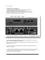
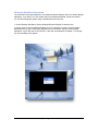
Users Guide for HauteSHOT microNVR video processing platform P.O. Box 4016, San Luis Obispo, California 93403 Phone: (800) 541-5589 (805) 541-WISP (9477) (310) 598-WISP (9477) Fax: (805) 456-3829 Email: [email protected] Web: www.hautespot.net Contents Contents .................................................................................................................................. 2 microNVR Quick Start .............................................................................................................. 3 Introduction.............................................................................................................................. 6 Components and Required Hardware ...................................................................................... 7 Basic Startup ........................................................................................................................... 8 Stand-Alone Computing Device ............................................................................................... 8 Alternate Headless Connection ................................................................................................ 9 Configuring Wireless Access .................................................................................................. 11 Third Party Application Support .............................................................................................. 11 Live Streaming using Windows Media Push ........................................................................... 21 HauteSpot HauteROUTER OS............................................................................................... 22 Comparison of SSD to HDD Drives in microNVR.................................................................... 23 Electrical Specifications and Connector Pins .......................................................................... 24 Audio Out .............................................................................................................................. 25 Mini-USB ............................................................................................................................... 25 SDIO Memory Slot ................................................................................................................. 25 Video (HDMI/DVI) .................................................................................................................. 26 Audio Out SPDIF ................................................................................................................... 26 Audio In (analog) ................................................................................................................... 27 SATA Drive Interface ............................................................................................................. 27 10/100/1000 RJ 45 Ethernet .................................................................................................. 28 Mini Serial Connector............................................................................................................. 28 LED Indicator Lights............................................................................................................... 28 System and Processor ........................................................................................................... 28 Federal Communications Commission Statement .................................................................. 30 User Guide for HauteSHOT microNVRv1_8.docxPage 2 of 30 2/15/2013 microNVR Quick Start Cabling and Powering on your microNVR IMPORTANT: The microNVR DOES NOT SUPPORT Power Over Ethernet (POE). Only use the provided 12VDC power supply. You will damage your microNVR if you feed power over the Ethernet ports. This damage is NOT COVERED BY WARRANTY. The microNVR has two setup options: 1. microNVR as a Stand-Alone Computing Device a. Attach a USB keyboard and mouse to the USB ports on the rear of the device. b. Attach the included antenna to the RPSMA antenna port on the rear of the device. c. Attach a HDMI or DVI monitor to the rear of the device. When using a DVI monitor you will need to use the provided HDMI to DVI adapter. d. Attach the power supply and the device will immediately power on. 2. microNVR as a Headless Computing Device a. Attach the included antenna to the RPSMA antenna port on the rear of the device. b. Attach an Ethernet cross over cable between Ethernet port 2 of the microNVR and your PC, or use an Ethernet switch. c. Attach the power supply and the device will immediately power on. d. The microNVR will provide a DHCP address to your computer. e. Log onto the microNVR using Windows Remote Desktop to address 192.168.168.1 and use user and password “hautespot”. f. This will present you with the MS Windows XP Professional desktop. The default user is “hautespot” with password of “hautespot”. Configuration The microNVR is running as a Windows 7 Professional SP1 pc with several special modifications. It is not, by default, routing. Ethernet port 1 is configured as the public network interface. It uses DHCP to request an IP address and configuration from an upstream router. Ethernet port 2 is configured as the private network with an IP address of 192.168.168.1. Ethernet port 2 is where you connect your camera, Ethernet switch or other network equipment. DHCP services for Ethernet Port 2 are provided by the DHCPd32.exe application which runs as a service. It can be found under Network Applications start menu program group. The local network is 192.168.168.1 and the microNVR will serve out addresses from 192.168.168.100 to 192.168.168.200. Wireless port 1 is configured as a Client which uses DHCP to connect and as a Virtual Access Point . The Virtual Access Point uses the native Windows Internet Connection Sharing or ICS which runs against Ethernet Port 1. The default SSID is micronvr and the default WPA2 key is 1234567890. The interface uses 802.11b/g/n on 2.4GHz. ICS automatically controls DHCP addresses on this port. The default address of the microNVR for wireless is 192.168.123.1 and DHCP will give out 192.168.123.2-192.168.123.254 to clients. Administration Before using your microNVR you should become familiar with its operation by downloading the user manual from the HauteSpot Networks website at www.hautespot.net. You will need to create User Guide for HauteSHOT microNVRv1_8.docxPage 3 of 30 2/15/2013 a user account for yourself on the web site, providing the serial number of your device and the date and place of purchase. Once logged into the web site, navigate to the HauteSHOT products download page by clicking Download, located under the Support tab, to retrieve the manual. You should also navigate to the HauteWRAP products manual and software pages to download and install the HauteSpot Networks Wireless Tools utility, the HauteSpot Networks Network Manager utility, and the complete HauteWRAP user manual, which includes all of the details of using the routing functions of your device. Third Party Software The microNVR comes with a variety of third party “trialware” which are installed on the Windows version of the product in the D: (Storage) drive. These software packages must be purchased and licensed through their respective manufacturers. Support for these packages and documentation may be found on their respective web sites. The microNVR user manual provides basic information on starting these products as services on the device. HauteSpot Networks does not support these products and makes no warranty claims regarding their suitability for use. Once you have installed whatever software from the D: drive, it is advisable to delete all other sample data from the drive in order to free up space for data storage. Of course this is up to you. If you would like to retain all of the installations, there is no other reason not to other than space. For more information, see page 31 or visit the HauteSpot Networks web site at www.hautespot.net. Embedded Operating System Boot Disk Protection Your microNVR runs a hybrid Windows 7 Professional SP1 operating system which provides the best of both a full desktop system and the disk write protection of an embedded operating system. Like any version of Windows 7 Professional, you can install applications, create data files, and make the system function in any way you require. However, in order to protect the boot partition from disk corruption due to improper power shutdown, the boot partition is write once, read many. All read/write activity is done to the D: Drive. We have moved some of the default file locations from Drive C: to Drive D: so that write activity to Drive C: is minimized. What this means is that when your microNVR boots up it reads the boot partition from your disk drive. The operating system creates a RAM disk that acts as a buffer between your boot partition and only temporarily stores your changes such as registry entries, boot file modifications, system boot file changes, etc. This RAM drive will be erased if power is lost or the system is restarted. HOWEVER, you can write your RAM drive to the boot partition, making your changes permanent by clicking on the “WRITE TO DRIVE C:” icon on your desktop. This will write out all temporary changes from the RAM drive to your hard disk so they are there when you reboot. After any of the following activities, you should click the WRITE TO DRIVE C: After installing a new program After uninstalling a program After making any changes to the Operating System Adding, deleting or changing users or user permissions Changing the startup of services Basically, if you are not sure you should click the WRITE TO DRIVE C: after any major activity where you want that configuration to survive a power reset. User Guide for HauteSHOT microNVRv1_8.docxPage 4 of 30 2/15/2013 Default settings for microNVR Windows Administrative User: hautespot Windows Admin Password: hautespot Local Network (Ether2): 192.168.168.1 * Local Network Gateway: 192.168.168.1 * Local Network DNS Server: 192.168.168.1 Local Network Subnet Mask: /24 or 255.255.255.0 Local Network DHCP Range: 192.168.168.100-192.168.168.200 VNC Password: hautespot Wireless Mode: Station with Virtual Access Point * Wireless SSID: microNVR * WPA2 AES Pre-shared Key: 1234567890 Wireless Band: 2.4GHz * Wireless Center Channel: Channel 1 (2412MHz) Wireless Standard: 802.11b/g/n Virtual Router Address 192.168.123.1 User Guide for HauteSHOT microNVRv1_8.docxPage 5 of 30 2/15/2013 Introduction The HauteSHOT microNVR is a Windows 7 Professional SP1 or Linux platform for running Video Management Services that come preconfigured as a wireless access point. This is a highly customized product which optimizes the software and operating system specifically for the hardware platform. While the version of Windows 7 Professional is the full desktop professional version with Service Pack 1 installed, it is not designed to be updated or modified using Microsoft Windows Update. Updating the operating system may cause damage to drivers, the Virtual Router or other system level components. HauteSpot Networks has taken great care to provide the latest system drivers, .NET v4, and related components in the system. Should you require updating the operating system, please contact HauteSpot Networks first. Applications and device drivers supporting devices such as USB modems or cameras can be safely installed. In order to optimize system performance, no virus, ad-ware or other security monitoring software is installed on the system. Such tools require significant processor overhead and slow performance. Please carefully scan all installation packages on another computer before installing them on the microNVR. User Guide for HauteSHOT microNVRv1_8.docxPage 6 of 30 2/15/2013 Components and Required Hardware In order to set up the system you will need: 1. The HauteSHOT microNVR hardware box which includes: a. The HauteSHOT microNVR processor platform b. 12 VDC power supply c. AC cord with North American or localized standard plug d. HDMI to DVI adapter e. 2.3mm to RCA cable f. 2 mini-USB to USB-A type adapters g. Mini-serial to DB-9 RS-232 cable 2. 3. 4. 5. h. Wireless Antenna A display with DVI or HDMI input A DVI or HDMI cable USB Keyboard USB Mouse Alternatively, if you desire to run the system headless, then you will need: 1. A MS Windows PC with 10/100/1000 Ethernet or 802.11b/g/n wireless network adapter 2. An installed copy of HauteSpot Networks Wireless Tools for Windows (may be installed on Linux using WINE or on Macintosh using a MS Windows emulator). This may be downloaded from the HauteSpot Networks Web site at http://www.hautespot.net/index.php/support/user-profile. You will need to first create a user account for yourself and then go back to the download section under HauteWRAP software. User Guide for HauteSHOT microNVRv1_8.docxPage 7 of 30 2/15/2013 Basic Startup Stand-Alone Computing Device 1. Connect antenna to the RPSMA WLAN connector on the rear of the unit. 2. Attach your monitor to the DVI port on the rear of the unit. 3. Attach your USB mouse to one of the two USB ports on the rear of the unit. 4. Attach your USB keyboard to one of the two USB ports on the rear of the unit. 5. Attach power to the power port on the rear of the unit. As soon as power is applied, the unit will power on. This is a normal feature. The unit will turn itself on once power is applied after any power loss. By default the unit will automatically log in to MS Windows, the VMS host of the machine, as the administrative user “admin”. At power on, the system runs at 1920x1280 pixels or 1080p. It is recommended to leave the system at this resolution. You will be presented with the Windows console of the system once the system fully boots. If you are asked for a user id or password during boot, you can use the default administrator id of “hautespot” and a password of “hautespot”. User Guide for HauteSHOT microNVRv1_8.docxPage 8 of 30 2/15/2013 Alternate Headless Connection The microNVR comes preconfigured to run Windows Remote Desktop, which is a remote desktop application. If you want to run your system without an attached keyboard, mouse and monitor, you can still manage the system using a standard personal computer. 1. Under Windows Start Menu, find the Windows Remote Desktop Connection item 2. Supply power to the microNVR and attach your PC to the Eth2 port with a crossover cable. Make sure that you get a valid DHCP address from the microNVR, and then open the RDP application. Log in with user id 192.168.168.1, with user and password “hautespot”. This will get you to the desktop of the system. User Guide for HauteSHOT microNVRv1_8.docxPage 9 of 30 2/15/2013 Ethernet Port Use Eth1 is your private network address. This port should be attached to your broadband connection (DSL modem, cable modem, etc.). Eth2 is the port you would connect to your IP cameras, an Ethernet switch, or LAN to which your cameras or other devices are attached. It is bridged with WLAN1 into the private network of Eth1. The following are the default settings for the system: VMS Host Administrative User: hautespot VMS Host Admin Password: hautespot VMS Host Display User: hautespot VMS Host Display User Password: hautespot VMS Host IP Address: 192.168.168.1 Local Network: 192.168.168.0/24 Local Network Gateway: 192.168.168.1 Local Network DNS Server: 192.168.168.1 Local Network Subnet Mask: /24 or 255.255.255.0 Local Network DHCP Range: 192.168.168.100-192.168.168.200 VNC Password: hautespot Wireless Mode: Client Mode with Virtual Access Point Wireless SSID: microNVR WPA2 AES Preshared Key: 1234567890 Wireless Band: 2.4GHz Wireless Center Channel: Channel 1 (2412MHz) Wireless Standard: 802.11b/g/n VAP Network 192.168.123.0/24 VAP IP Address 192.168.123.1 VAP Network Gateway 192.168.123.1 VAP Subnet Mask /24 or 255.255.255.0 VAP Network DHCP Range: 192.168.123.2-192.168.123.254 User Guide for HauteSHOT microNVRv1_8.docxPage 10 of 30 2/15/2013 Configuring Wireless Access The wireless interface is controlled through windows networking. Refer to information on using Windows Wireless Client for more information. The Virtual Access Point is started automatically by a command script which can be found in the Startup Menu Item of the Windows Start button. If you do not want to use the VAP, delete this item from the Startup Menu Item and go into Network Sharing Connections and disable the VAP interface. You can reconnect it later by copying the VAP start item into startup and renabling the interface Third Party Application Support The microNVR comes with a variety of third party “trialware” installation packages that are located on the D:\ drive partition. You may install your choice of these programs as needed. These programs should be installed and configured to write to the D:\ drive partition, as the C:\ drive partition is reserved for system files only. These software packages must be purchased and licensed through their respective manufacturers. Support for these packages and documentation may be found on their respective web sites. This user manual provides basic information on starting these products as services on the device. HauteSpot Networks does not support these products and makes no warranty claims regarding their suitability for use. Installation Packages Available located at D:\3rd Party Surveillance Software: Arecont AV100_Software Avigilon AvigilonCameraInstallationTool AvigilonControlCenterClient AvigilonControlCenterGateway AvigilonControlCenterPlayer AvigilonControlCenterServerAXIS AMC_Embedded_msi.msi AXISCameraManagementSetup.exe AXISCameraStationSetup.exe AxisMatroskaSplitterSetupPackage.zip AXISMobileMonitorSetup.msi AxisVideoCaptureDriverSetup.msi IPUtility Basler Basler_IP-Camera_Control.zip BIP_Finder IPCam_Reset_Tool.zip Blue Iris BlueIris.exe User Guide for HauteSHOT microNVRv1_8.docxPage 11 of 30 2/15/2013 Canon vbsetup viewer ClearPix ClearPixCameraInstallationTool ClearPixVMSPlayerVMSClientVMSGatewayVMSServerExacq exacqVision.exe IQInVision IQaccess iqeyectrl.zip iqfinder_installer.msi IQmanager iqstream.exe netstream.zip Milestone MilestoneXProtectSmartClient.exe Mobotix MX_system_ MX_system_ MxEasy OnSSI NetDVMS Panasonic EasyIpSetup i_pro_ConfigSoftware IPSetup.zip viewersoftware Sony Media_File_Player Real_Shot_Manager_Advanced Toshiba CF_Installer Vivotek iw2.zip shepherd.zip st2403.zip st3402_en.zip st7501.zip User Guide for HauteSHOT microNVRv1_8.docxPage 12 of 30 2/15/2013 For more information, visit the HauteSpot Networks web site at www.hautespot.net exacqVision server, client and web server – This is a complete installation, with a trial license for one camera. To run the server, simply open the Computer Management utility, and go to Services, find the exacq server, exacq web server and Light HTTPD server services. Right click on each and change their startup state to automatic. Then start each service. You will need to purchase an additional license for any additional cameras you wish to use. In order to auto start the exacqVision software on the microNVR so that it will run at system boot, you will need to enable three services using the Computer Management console services: exacqVisionServer, exacqVisionWebServer, and exacqVisionLightHTTPDServer. User Guide for HauteSHOT microNVRv1_8.docxPage 13 of 30 2/15/2013 User Guide for HauteSHOT microNVRv1_8.docxPage 14 of 30 2/15/2013 Network Optix software – This is free video client management software for demonstration purposes. User Guide for HauteSHOT microNVRv1_8.docxPage 15 of 30 2/15/2013 Blue Iris – This is a complete video management system. Again, you can automatically start the server using the Services menu in Computer Management. You will need to purchase a user license agreement if you wish to use this software. It will run in evaluation mode for 15 days User Guide for HauteSHOT microNVRv1_8.docxPage 16 of 30 2/15/2013 Axis Camera Station – Axis Camera Station is free to use, but will only support Axis cameras. Again, there is a service in Computer Management which will automatically start the VMS software. User Guide for HauteSHOT microNVRv1_8.docxPage 17 of 30 2/15/2013 MileStone Systems Xprotect Go – This VMS supports up to four cameras without additional licenses. After this, a license needs to be purchased. In all cases the software should be registered with MileStone Systems. There are several services in Computer Management that need to be started. All of these services are prefixed with the MilesStone name. Sony RealShot Manager – This VMS works exclusively with Sony brand cameras. There are several services in Computer Management that need to be set for auto run in User Guide for HauteSHOT microNVRv1_8.docxPage 18 of 30 2/15/2013 order for the system to come up on boot. All are prefixed with the name Sony. User Guide for HauteSHOT microNVRv1_8.docxPage 19 of 30 2/15/2013 Microsoft Media Encoder – This is free video encoder software. It can be set to run automatically as a service. Microsoft Expression Encoder 4 – This is a free video encoder for Silverlight environments. Adobe Flash Media Encoder – This is a free video encoder which renders in flash format for push to a variety of web streaming services. LiveStream ProCaster – This is a free video encoder which renders in streaming format for the LiveStream service. Real Networks Helix Encoder – A free encoder for use with Real Networks systems. WireShark – Network Packet Analyzer which can be used to diagnose system issues. HauteSpot Networks does not provide support for these applications. You will need to refer to the software manufacturer for service and support of these products. HauteSpot Remote Support – This tool allows HauteSpot Networks Technical Support engineers to remotely access your microNVR, provided that it is connected to the Internet. Simply launch the application from the start menu under the HauteSpot Networks program group. Call technical support and give them the session ID and access code. We can then log directly into your system for troubleshooting. This feature is not used unless you affirmatively start the application. User Guide for HauteSHOT microNVRv1_8.docxPage 20 of 30 2/15/2013 Live Streaming using Windows Media Push One of the most challenging aspects of remote video streaming, particularly over 3/4G is the reliability of the links. Traditional surveillance architectures are based on “server pull” where the VMS makes a request to the camera or remote NVR to start a video stream. It requires that the VMS knows the IP address of the camera or remote NVR and that the address is reachable. With carrier provided wireless networks, the IP address of the camera or remote NVR can constantly change. A better approach is to use a camera/remote NVR push to the main video server. HauteSpot Networks has developed a comprehensive solution to this problem using Windows Media Services where outbound push streaming can be accomplished from the microNVR to a destination, Windows Media Server, and then the stream can be rebroadcasted as needed to web sites or remote applications. This architecture is offered as a service. Contact HauteSpot Networks for more information. Internet 3G Cellular (Verizon EvDO) Client Viewer (Anywhere in the world) Axis 223M Ethernet to microNVR (HauteSpot Office) microNVR w/ 3G modem (HauteSpot Office) Windows IIS 6 Server With Windows Media Services Extension (HauteSpot Office) Windows IIS 7 Server Web Server with Silverlight Player Page (AccuWeb Hosting) Demonstration Site for Live Wireless Streaming Over 3G http://www.hcvideo.biz/camera5.html 640x480 at 5fps H.264 PUSH streaming from microNVR Tolerant of network changes, drops and outages User Guide for HauteSHOT microNVRv1_8.docxPage 21 of 30 Wireless Network Design 2011 © HauteSpot Networks Corporation 2/15/2013 HauteSpot HauteROUTER OS The microNVR comes preinstalled with a fully functioning version of the HauteSpot HauteROUTER OS routing system. This runs as a virtual machine on your microNVR and is started as a Windows service. You can find the service under Service Manager. There are two virtual Ethernet interfaces defined and routed to the virtual router, one is bridged to the rest of the private network and the other is a stand alone host interface. You can connect to the virtual router at 192.168.168.2 or you can use the HS Configurator layer 2 discovery tool to connect to it. With the virtual router you can capture all of the physical interfaces of the microNVR and bridge them, route to them, set up firewalls, run NAT, run VPN tunnels and much much more. Configuration of the virtual router is usually fairly complex and required only when the base functions of the microNVR (DHCP, DNS, NTP, Proxy, etc) are not sufficient. Contact HauteSpot Technical Support for assistance in configuring the virtual router. User Guide for HauteSHOT microNVRv1_8.docxPage 22 of 30 2/15/2013 Comparison of SSD to HDD Drives in microNVR Storage Capacity (RAW) SSD 128GB Rotational Speed Weight N/A 77g HDD 500GB or 1TB 5400 RPM or 7200 RPM 99g Power Consumption Idle Power Consumption Active .5W 2W .81W 2.85W Operation Temp Shock Resistance -45 to +85 deg C 1500G -0 to 60 deg C 350G MTBF ECC Recovery 2 Million Hours Up to 24 bytes per 512 byte sector 600,000 Hours N/A Max Read Max Write 285MB/s 275MB/s 300MB/s 286MB/s Sustained Write 4KB Random Write Seek Time Latency Operating Noise 250MB/s 50K IOPS .1ms N/A 0 dBA 250MB/s 27K IOPS 14ms 5.6ms 26 dBA User Guide for HauteSHOT microNVRv1_8.docxPage 23 of 30 2/15/2013 Electrical Specifications and Connector Pins User Guide for HauteSHOT microNVRv1_8.docxPage 24 of 30 2/15/2013 Audio Out Mini-USB SDIO Memory Slot User Guide for HauteSHOT microNVRv1_8.docxPage 25 of 30 2/15/2013 Video (HDMI/DVI) Audio Out SPDIF User Guide for HauteSHOT microNVRv1_8.docxPage 26 of 30 2/15/2013 Audio In (analog) SATA Drive Interface User Guide for HauteSHOT microNVRv1_8.docxPage 27 of 30 2/15/2013 10/100/1000 RJ 45 Ethernet Mini Serial Connector LED Indicator Lights System and Processor The Intel® Atom Z5xx series processor is built on 45-nanometer process technology — the first generation of low-power IA-32 micro-architecture specially designed for the new class of Mobile Internet Devices (MID). The following list provides some of the key features on this processor: • New single-core processor for mobile devices with enhanced performance • On die, primary 32-kB instructions cache and 24-kB write-back data cache • 100-MHz and 133-MHz Source-Synchronous front side bus (FSB) User Guide for HauteSHOT microNVRv1_8.docxPage 28 of 30 2/15/2013 • Supports Hyper-Threading Technology 2-threads • On die 512-kB, 8-way L2 cache • Support for IA 32-bit and Intel® 64 architecture • Intel® Virtualization Technology (Intel® VT) • Intel® Streaming SIMD Extensions 2 and 3 (Intel® SSE2 and Intel® SSE3) and Supplemental Streaming SIMD Extensions 3 (SSSE3) support • Supports new CMOS FSB signaling for reduced power • Micro-FCBGA8 packaging technologies • Thermal management support via TM1 and TM2 • FSB Lane Reversal for flexible routing • Supports C0/C1(e)/C2(e)/C4(e) • New C6 Deep Power Down Technology • L2 Dynamic Cache Sizing • New Split-VTT support for lowest processor power state • Advanced power management features including Enhanced Intel SpeedStep® Technology • Execute Disable Bit support for enhanced security The HauteSHOT microNVR uses an Intel® System Controller Hub (Intel® SCH) US15W chipset. The Intel® SCH chipset component of the Atom low power platform combines functionality normally found in separate GMCH (integrated graphics, processor interface, memory controller) and ICH (on-board and end-user I/O expansion) components into a single component consuming less than 2.3 W of thermal design power. The HauteSHOT microNVR graphics system is based on the Intel® SCH integrated graphics controller, based on Intel® GMA500 architecture. The HauteSHOT microNVR board features an HDMI connector (J14) providing DVI output. DVI output is formed using a Chrontel CH7307C DVI transmitter in revisions 1.2 and 1.2x. The Intel SCH provides integrated graphics (2D and 3D) and high-definition video decoder capabilities with minimal power consumption. The highly compact IGD contains advanced shader architecture (model 3.0+) that performs pixel shading and vertex shading within a single hardware accelerator. The processing of pixels is deferred until they are determined to be visible, which minimizes access to memory and improves rendering performance. The Intel SCH supports full hardware acceleration of video decoding standards such as H.264, MPEG2, MPEG4, VC1, and WMV9. User Guide for HauteSHOT microNVRv1_8.docxPage 29 of 30 2/15/2013 Federal Communications Commission Statement This device contains one or more of the following modular components which have been tested and approved as “FCC approved modules”. FCC ID for each module is as follows: VQF-RT7070HMC 1. Each modular transmitter has its own RF shielding (the shielding must enclose all RF circuitry). 2. Each modular transmitter has buffered modulation/data inputs. 3. Each modular transmitter has its own power supply regulation to ensure that the module will comply with Part 15 requirements regardless of the design of the power supplying circuitry for the host. (U. S.) 4. The certification submission shall contain a detailed description of the configuration of all antennas that will be used with the module. All modules are approved for use with 4dBi gain rubber duck type omni directional antennas. 5. Each modular transmitter has a "unique" antenna coupler (at all connections between the module and the antenna, including the cable). The "professional installation" provision of Section 15.203 may not be applied to modules. (U. S.) 6. Each modular transmitter has been tested in a stand-alone configuration. (U.S.) 7. Unless battery powered, each module complies with the AC line conducted requirements found in Section 15.207 (U. S.) 8. Each module meets Industry Canada's certification labeling requirements. And each host device shall also comply with the certification labeling requirements of each of the modules it contains. (Canada) 9. Each modular transmitter has been labeled with its own FCC ID number and the label is visible form the outside of the host device. Each host device also displays a label referring to the enclosed module's FCC ID. (U. S.) 10. Each modular transmitter complies with any specific rule or operating requirements applicable to the transmitter and the manufacturer must provide adequate instructions with the module to explain any such requirements. 11. The host device and all the separately certified modules it contains jointly meet the RF safety requirements of RSS102, if applicable. (Canada) 12. Each modular transmitter complies with any applicable FCC RF exposure requirements. (U.S.) Changes or modifications not expressly approved by the manufacturer could void your right to operate the equipment. Test reports for each module and emissions test reports for the host computer board are available on request. CE Declaration of Conformity We, HauteSpot Networks Corporation, declare that the microNVR series of routers is in conformance with: - EN 61000-6-3 and EN 61000-6-4 (EMI emissions, residential and industrial) - EN 61000-6-1 and EN 61000-6-2 (ESD, susceptibility, residential and industrial) A copy of the test report will be provided on request. User Guide for HauteSHOT microNVRv1_8.docxPage 30 of 30 2/15/2013