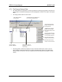
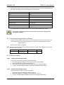
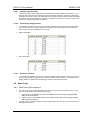
1
Document No. 996-140-000-9 Issue 9 FIRE 6.21 user manual MORLEY-IAS FIRE 6.21 User Manual Table of Contents 1 INTRODUCTION ......................................................................................................................... 4 1.1 Notice ...................................................................................................................................... 4 1.2 Warnings and Cautions......................................................................................................... 4 1.3 National Approvals ................................................................................................................ 4 2 DESCRIPTION ............................................................................................................................ 5 2.1 Product Features ................................................................................................................... 5 2.2 PC Requirements ................................................................................................................... 5 3 3.1 4 4.1 INSTALLATION .......................................................................................................................... 6 How to Install the Application .............................................................................................. 6 OPERATION ............................................................................................................................... 7 Starting the Program ............................................................................................................. 7 4.2 Opening a File / Creating a New File.................................................................................... 8 4.2.1 New File............................................................................................................................ 8 4.2.2 Opening a File .................................................................................................................. 8 4.2.3 Old Configuration Files ..................................................................................................... 8 4.2.4 File History........................................................................................................................ 8 4.3 Main Screen Features............................................................................................................ 9 4.3.1 Menu Bar and Speed Buttons .......................................................................................... 9 4.3.2 Main Screen Views ......................................................................................................... 12 4.4 Loop Configuration.............................................................................................................. 18 4.4.1 A Quick Tour of the Loop Editor ..................................................................................... 18 4.4.2 Settings Associated with an Address ............................................................................. 19 4.4.3 Inserting a Device ........................................................................................................... 20 4.4.4 Inserting a Device with a Base Sounder ........................................................................ 20 4.4.5 Inserting Multi-Input Devices .......................................................................................... 21 4.4.6 Deleting a Device............................................................................................................ 21 4.4.7 Changing Device Settings .............................................................................................. 22 4.5 Editing Zone Text................................................................................................................. 25 4.6 Outputs ................................................................................................................................. 26 4.6.1 A Note about Outputs ..................................................................................................... 26 4.6.2 The Outputs Editor.......................................................................................................... 27 4.6.3 Configuring Output Settings ........................................................................................... 28 4.6.4 Hochiki Sounders............................................................................................................ 28 4.6.5 Apollo Discovery Sounder Beacons ............................................................................... 29 4.7 Ringing Patterns .................................................................................................................. 30 4.7.1 Adding a New Ringing Pattern ....................................................................................... 30 4.7.2 The Ringing Patterns Editor ........................................................................................... 31 4.7.3 Selecting a Ringing Pattern for Editing........................................................................... 32 Page 2 of 51 Document No 996-140-000-9, Revision: 9 User Manual FIRE 6.21 User Manual 4.7.4 MORLEY-IAS Editing a Pattern ..............................................................................................................32 4.8 Event Logic ...........................................................................................................................33 4.8.1 The Event Logic Sequence .............................................................................................33 4.8.2 The Event Logic Editor ....................................................................................................34 4.8.3 Testing Events.................................................................................................................35 4.8.4 Clearing Events ...............................................................................................................35 4.9 General Project Details ........................................................................................................35 4.9.1 The General Options Editor.............................................................................................35 4.9.2 Site Details and Notes .....................................................................................................35 4.9.3 Panel Details ...................................................................................................................36 4.10 Cut, Copy and Paste .........................................................................................................36 4.10.1 Copying Functionality ......................................................................................................36 4.10.2 Copying a Device ............................................................................................................36 4.10.3 Limitations .......................................................................................................................36 4.11 Saving a File ......................................................................................................................36 4.12 Panel Communications ....................................................................................................37 4.12.1 Comms Setup..................................................................................................................37 4.12.2 Linking To a Panel...........................................................................................................38 4.12.3 Configuring a Panel from the PC.....................................................................................38 4.12.4 Configuring the PC from a Panel.....................................................................................39 4.12.5 Interactive Panel Display .................................................................................................39 4.12.6 Panel Event Log ..............................................................................................................44 4.12.7 Establishing a Remote Connection .................................................................................45 4.13 Contact Management........................................................................................................46 4.13.1 Accessing the Contacts Form .........................................................................................46 4.13.2 Editing Contacts ..............................................................................................................47 4.13.3 Inserting New Entries ......................................................................................................48 4.13.4 Deleting an Entry .............................................................................................................48 4.14 Printing and Previewing Reports ....................................................................................49 4.14.1 Methodology ....................................................................................................................49 4.14.2 Printing a Report..............................................................................................................49 4.14.3 Previewing a Report ........................................................................................................50 4.14.4 Printing the Event Log .....................................................................................................50 5 UPGRADING EXISTING PANELS............................................................................................51 5.1 Introduction ...........................................................................................................................51 5.2 How to Perform the Upgrade ...............................................................................................51 User Manual Document No 996-140-000-9, Revision: 9 Page 3 of 51 MORLEY-IAS FIRE 6.21 User Manual 1 Introduction 1.1 Notice The material and instructions covered in this manual have been carefully checked for accuracy and are presumed to be correct. However, the manufacturer assumes no responsibility for inaccuracies and reserves the right to modify and revise this document without notice. These instructions cover the use and operation of the ZX Windows Configuration Tool. Refer to the Fire Alarm Control Panel Commissioning Manual for information on setting up the Fire Panel to be programmed using the Configuration Tool. 1.2 For use with panel software version 845 onwards Warnings and Cautions These instructions contain procedures to follow in order to avoid injury and damage to equipment. It is assumed that the user of this manual has been suitably trained and is familiar with the relevant regulations. All equipment is to be operated in accordance with the appropriate standards applicable 1.3 National Approvals This equipment must be installed and operated in accordance with these instructions and the appropriate national, regional and local regulations specific to the country and location of the installation. Consult with the appropriate Authority Having Jurisdiction (AHJ) for confirmation of the requirements. EN54-2 13.7 EN54 ! Page 4 of 51 Maximum of 512 sensors / manual call points per panel. The ZXe and ZXSe range of panels have many features, which if used inappropriately, may contravene the requirements of EN54. Where such a possibility may arise, a suitable warning is given with brief details of the EN54 requirement and the relevant section it pertains to. A typical EN54 non-compliance warning is illustrated. Document No 996-140-000-9, Revision: 9 User Manual FIRE 6.21 User Manual 2 Description 2.1 Product Features MORLEY-IAS The following features are provided by the PC Programming Tool: 1. Programming the ZX range of fire panels (ZX1e/ZX1Se, ZX2e/ZX2Se, ZX5e/ZX5Se) 2. Report Printout of Configuration Settings 3. File Storage of Configuration settings for use by other applications software 4. Report Printout of the panel Event Log 5. Loop and Battery Calculation 6. Diagnostics. NOTE: FIRE 6.16, or later, have not been validated with panel software versions prior to version 760. It may be possible to configure ZX1, ZXa and ZXe panels fitted with earlier software versions; however, MIAS does not guarantee or warrant that any such configuration will work, and it is the responsibility of the user to carefully check any such installations. If in doubt, continue to use FIRE 5 for earlier panel software versions. 2.2 PC Requirements To run the program will require a PC with the following specification or better. 1. Pentium 100MHz 2. Windows 98SE, ME, NT, 2000, XP 3. 32Mbyte RAM 4. 10Mbyte Free Hard Disk Space 5. The PC should be configured for operation with a monitor resolution of at least 640*480 (preferably 800*600 or better) and 8-bit colour mode. 6. It is recommended that the PC be fitted with a graphics card with at least 1 megabyte of memory. User Manual Document No 996-140-000-9, Revision: 9 Page 5 of 51 MORLEY-IAS FIRE 6.21 User Manual 3 Installation 3.1 How to Install the Application The application is installed as a Windows program. On the CD there is a folder called ‘SW993-738 ZX Config Tool’, which contains a single executable file. Run this file (by double-clicking or else by starting it in the Start menu’s ‘Run…’ option) and follow all the prompts that appear. This will install FIRE 6.nn in the Start menu. Page 6 of 51 Document No 996-140-000-9, Revision: 9 User Manual FIRE 6.21 User Manual MORLEY-IAS 4 Operation 4.1 Starting the Program The program can be started from the shortcut icon displayed on the desktop. When the program is first started a splash screen displaying the company logo will be shown. The following window will appear which prompts either to start a new project or to access an existing project by opening a configuration file. Fire 6.nn Startup Dialog Box To Start a New Project 1 Select this button for a new project 2 Then choose the maximum number of loops on the panel 3 Then choose the device protocol from this box To Open an Existing File Click here once you have set the choices (New or Open) Select this button to open a file This box prompts you to select either opening a file or creating a new file and only appears at program startup. However, these operations may be carried out at any time by a variety of methods: User Manual Drop-down menu items Speed-buttons (on the main screen’s tool bar) Special keystroke sequences (‘accelerator keys’) Document No 996-140-000-9, Revision: 9 Page 7 of 51 MORLEY-IAS 4.2 FIRE 6.21 User Manual Opening a File / Creating a New File 4.2.1 New File Selecting ‘New’ from the toolbar or ‘File’ menu creates a new blank project. At this point, no devices are configured on any loops, there are no text descriptions for addresses or zones, and there are no configured event logic sequences. A number of defaulted onboard outputs are created, according to the capability of the panel, and each such output is allocated a unique ringing pattern number. All patterns are defaulted to the same settings: all zones are in the ON mode. When a new file is created, the following information must be specified: Panel type: determined by number of available loops 1 loop 2 loops 5 loops ZX1, ZX1e, ZX1Se ZXA, ZX2e, ZX2Se ZXE, ZX5e, ZX5Se Device manufacturer: from a subset of the following Apollo Hochiki Nittan Morley-IAS System Sensor Once set, these parameters remain constant for a given project. In this respect, FIRE 6.nn differs from FIRE 5, where the device manufacturer could be changed in mid-project. 4.2.2 Opening a File On startup, an existing file may be opened instead of creating a new project. In this case, a standard Windows ‘Open File’ dialog box appears which can be navigated in the usual way. Note that FIRE 6.nn configuration files have the extension .ZXF, and that the dialog box filters the file list for files of this extension. 4.2.3 Old Configuration Files The Fire 6.nn application is backwards compatible with files created using any previous Windows version of the configuration tool (Fire 6.0 onwards). These files have a .ZXF extension. If a configuration file, originally created using an old version of Fire 6 is saved with the same name, it will no longer be possible to open it using the old version of the configuration tool. It is highly recommended that configuration settings are rechecked, when using a file created using an old version of the configuration tool. Old FIRE 5 files, with a .TXT extension, cannot be used with FIRE 6, or later. 4.2.4 File History A list of the 5 most recently used files can be accessed from the File menu. The list is updated and re-ordered each time a file is opened or saved. Page 8 of 51 Document No 996-140-000-9, Revision: 9 User Manual FIRE 6.21 User Manual 4.3 MORLEY-IAS Main Screen Features 4.3.1 Menu Bar and Speed Buttons Once the above choices have been made, the main screen appears. Menu toolbar Speedbutton toolbar Minimize Resize Exit Main screen area User Manual Document No 996-140-000-9, Revision: 9 Page 9 of 51 MORLEY-IAS 4.3.1.1 File Handling Menu (FILE) The top left-hand corner of the main form holds the menus and the file handling speed buttons: 2 1 4.3.1.2 FIRE 6.21 User Manual 3 4 5 6 7 8 These buttons are: No. Name Function Keystroke 1 New Create a new file <Ctrl> + N 2 Open Open an existing file <Ctrl> + O 3 Save Save the current project <Ctrl> + S 4 Print Print all or part of data <Ctrl> + P 5 Preview Preview the print layout on screen 6 Cut Remove a device from its address and save to clipboard. <Ctrl> + X 7 Copy Save device to clipboard but do not remove from address. <Ctrl> + C 8 Paste Save device on clipboard to current address. <Ctrl> + V None Data Editing Menu (EDIT) This menu allows the navigation between the different editor screens. These are: Item No Menu Item Description 1–5 Main Loops Allows devices to be inserted into a loop, deleted, or have settings changed 6 Peripheral Loop As above, but for the Peripheral loop 7 Zone Text Edit textual description of any zone 8 Outputs Edit the properties and associated ringing pattern and events for any onboard and loopbased output points 9 Ringing Patterns Edits zonal range settings for ringing patterns 10 Event Logic Edits settings for up to 60 event logic (‘cause & effect’) sequences 11 General Options Allows project details and comments to be attached to the project Page 10 of 51 Document No 996-140-000-9, Revision: 9 User Manual FIRE 6.21 User Manual 4.3.1.3 4.3.1.4 Utilities Menu (TOOLS) The following utilities are provided in the tools menu: a) Contact Management b) Loop & Battery Calculator c) Options 1 Panel Communication Menu (COMMUNICATIONS) Panel Communications area of the toolbar. These buttons (each of which has a corresponding menu item and accelerator key) are: Name Description 1 Configure Panel Send the configuration data from the PC to the panel 2 Configure PC Send the panel’s configuration data to PC (overwriting the existing PC data) 3 Interactive Panel Display Provides diagnostic information regarding the panel and provides an interactive panel fascia, through which the panel menus can be navigated. 4 Download Event Log This retrieves the history log of the panel and provides facilities to filter it, print it and save it. 5 Communications Setup Specify the panel network address and serial port. 4.3.1.5 1 MORLEY-IAS Help Menu (HELP) This contains two menu items: a) User Manual: opens this help manual. b) About…: standard program information This allows the selection of HBS TC800 loop protocol; requires a password. User Manual Document No 996-140-000-9, Revision: 9 Page 11 of 51 MORLEY-IAS FIRE 6.21 User Manual 4.3.2 Main Screen Views 4.3.2.1 General Options This is shown below. This is the default screen, which appears whenever a new project is created or a configuration file is opened. It also appears when the General Options menu item is selected. Menu toolbar Speedbutton toolbar Minimize Resize Exit Main screen area Page 12 of 51 Document No 996-140-000-9, Revision: 9 User Manual FIRE 6.21 User Manual 4.3.2.2 MORLEY-IAS Device Loop Editor This is shown below. The device loop editor displays details for one loop (which may be one of the main loops or the Peripheral Loop), and is selected from the appropriate speed button, or by selecting Edit in the menu bar, then Loops, then the appropriate loop. User Manual Document No 996-140-000-9, Revision: 9 Page 13 of 51 MORLEY-IAS 4.3.2.3 FIRE 6.21 User Manual Zone Text Editor This is shown below. The zone text editor displays textual descriptions for all zones and is selected from the ‘Zone Text’ speed button, or by selecting Edit in the menu bar, then Zone Text. Page 14 of 51 Document No 996-140-000-9, Revision: 9 User Manual FIRE 6.21 User Manual 4.3.2.4 MORLEY-IAS Outputs Editor A 5-loop panel has 6 onboard outputs, and all other panels have 4. If the panel does not have 6 onboard outputs then there will be 2 outputs marked as reserved in the editor. The settings for these should not be changed. The outputs editor displays details of all outputs (both onboard the panel and associated with loops) and is selected from the Outputs speed button, or by selecting Edit in the menu bar, then Outputs. User Manual Document No 996-140-000-9, Revision: 9 Page 15 of 51 MORLEY-IAS 4.3.2.5 FIRE 6.21 User Manual Ringing Patterns Editor This is shown below. The ringing patterns editor displays the complete list of ringing patterns and the full zonal settings for one highlighted pattern and is selected from the Patterns speed button (F9), or by selecting Edit in the menu bar, then Ringing Patterns. Page 16 of 51 Document No 996-140-000-9, Revision: 9 User Manual FIRE 6.21 User Manual 4.3.2.6 MORLEY-IAS Event Logic Editor This is shown below. The event logic editor displays all settings for 60 event logic sequences, and is selected from the Event Logic speed button (F10), or by selecting Edit in the menu bar, Event Logic. User Manual Document No 996-140-000-9, Revision: 9 Page 17 of 51 MORLEY-IAS 4.4 FIRE 6.21 User Manual Loop Configuration 4.4.1 A Quick Tour of the Loop Editor The Loop editor is shown below, and contains the following features: Device selector Loop configuration grid Loop identifier Insert/ remove mode selector buttons - Loop identifier: Displays the loop number (or ‘Peripherals’) - Mode selector buttons: Toggle these to select device insertion or removal mode. The appropriate button being highlighted indicates the mode. - Device Selector: A drop down list of insertable devices. - Loop Configuration Grid: The main grid that shows details of each address and its associated device. This grid is vertically scrollable, and in most screen resolutions will be horizontally scrollable also, owing to the amount of data displayed for each address. Page 18 of 51 Document No 996-140-000-9, Revision: 9 User Manual FIRE 6.21 User Manual MORLEY-IAS The Loop Configuration Grid contains the following columns: Name Description Address The number of the address, sequentially increasing from 1 to the maximum number of devices for a loop (which depends upon the device manufacturer). This column cannot be changed. Description Up to 20 characters of device location text can be entered here. Device Type Information about the specific device inserted at the address. Defaults to ‘<not used>’ if no device is inserted. Zone The zone number to which the address is assigned. Event The causal event associated with the address. Group The isolation group associated with the address. Inputs The number of input points of the device. Input Action The action associated with the device’s input. Defaults to ‘<no action>’ if no device present. Note: For multi-input devices, the Action for input no. 1 is shown. Pre The pre-alarm threshold (sensors only). Fire The full alarm threshold (sensors only). Sensitivity Band This column can be used to set the sensitivity band for Apollo Discovery devices. Outputs The number of output points of the device. 4.4.2 Settings Associated with an Address The following parameters are features associated with an address, and not the device itself, so they may be set whether a device is present at the address or not: a) Description (text) b) Zone (number) default 1 (all address slots belong to a zone) c) Event (number) default 0 (no event) d) Group (number) default 0 (no group) e) These are set by navigating to the appropriate grid cell using tab/arrow keys or mouse, and entering the value required. User Manual Document No 996-140-000-9, Revision: 9 Page 19 of 51 MORLEY-IAS FIRE 6.21 User Manual 4.4.3 Inserting a Device This is done by following these steps: 1. Ensure the editor is in insertion mode by clicking the ‘Insert’ button. 2. Drop down the device list and select the required device. 3. If applicable, specify whether the device has a base sounder fitted. 4. To insert the device, double click on the address number required or alternatively highlight the required address and then press the INSERT key. Device selector Some devices can be specified as having a base sounder fitted Select insert mode Double-click in the address column to insert the selected device Note: If a device is already present at the required address, it is automatically deleted when a new device is inserted. 4.4.4 Inserting a Device with a Base Sounder The following information applies to both Apollo remote LED Ancillary Sounders and Hochiki Base Sounders. A device with a base sounder can be added by following these simple steps: 1. 2. 3. Place the Loop Editor into insertion mode by clicking the ‘Insert’ button. Drop down the device list and select the required device. This should cause a base sounder option to be displayed to the right of the device list. If this is not displayed it is because the device does not support a base sounder and another device should be chosen. Change the base sounder option to indicate that the device has a base sounder fitted. The device can now be added in the normal way, by double click on the address number required or by alternatively highlighting the required address and then press the INSERT key. The presence of a base sounder is indicated by the image display in the address column, alongside the address number. Page 20 of 51 Document No 996-140-000-9, Revision: 9 User Manual FIRE 6.21 User Manual MORLEY-IAS 4.4.5 Inserting Multi-Input Devices When a multi-input device is inserted, and sufficient addresses are left on the loop, an option is given to insert the device in expanded mode. In expanded mode, each input point of the device is assigned to a separate loop address, starting with the address originally selected for the first input and increasing sequentially for each additional input. This allows text, zone number, event number and isolation group to be on an input-by-input basis, instead of being common for all. Notes: Device output points are always associated with the first address occupied. The range of addresses used in an expansion is highlighted in the grid with a grey background. Expanding a device may result in an existing device being removed, if the device is within the address range used in the expansion. When this scenario occurs, a warning will be given, and confirmation will be required to proceed. 4.4.5.1 Expanding an Unexpanded Device (and vice versa) The Fire 5 DOS version of the tool allowed devices to be toggled between expanded and unexpanded modes after insertion. In some circumstances this caused confusion so Fire 6 does not allow the mode to be changed after device insertion. To change the expansion mode of a multi-input device the device must first be deleted and then reinserted in the desired mode. 4.4.5.2 System Sensor MMX-10M and CMX-10RM Modules – a Special Note The MMX-10M is a 10-way input module, and the CMX-10RM is a 10-way output module. The configuration tool supports these devices in the following way: The MMX-10M, when downloaded from a panel, will appear in the FIRE6 loop editor as a block of 10 Generic manual call points, occupying 10 consecutive addresses. When inserting the module at the PC, the same method should be used; insert call points at a block of 10 empty addresses. Similarly, the CMX-10RM appears as 10 Generic output control modules (i.e. Relays), and should be entered at the PC in this manner. 4.4.5.3 Morley-IAS Micro-Monitor Module – MI-MM3 The Morley-IAS MI-MM3 micro-monitor module has an option for selecting an ancillary LED. When an MI-MM3 module is selected from the device list an additional box is displayed to the right of the device list box. This additional box allows the ancillary LED function to be selected. The default is for the LED ‘not to be fitted’. Important Note: The Loop & Battery calculator must be used to determine the maximum number of ancillary LEDs capable of being supported on each loop. 4.4.6 Deleting a Device To delete a device: a. b. Select Removal mode (Remove button highlighted) Double-click on the address column for the required row. Alternatively (without the mouse), navigate to it and press the DELETE key. The device-independent settings (description, zone etc.) remain and must be changed or deleted individually. User Manual Document No 996-140-000-9, Revision: 9 Page 21 of 51 MORLEY-IAS FIRE 6.21 User Manual 4.4.7 Changing Device Settings 4.4.7.1 In general, settings can only be modified if they are applicable to the inserted device. The following device settings may be changed in the Loop Editor where appropriate: Input Actions Switching devices such as MCP have a default input setting of ‘Confirmed Fire’. Alternatively, you can select one of the other listed input actions: <no action> Fault Warning Zone Fire Bomb Alert Class Change Security Non-latching Plant Warning Group Disable Confirmed Fire Reset Evacuate Silence/Resound Note that sounders have an implicit ‘Fault Warning’ setting and relays have an implicit ‘<no action>’ setting. Sensor devices and zone monitors default to ‘Zone Fire’, and the only actions allowed for sensors are ‘Zone Fire’ and ‘Confirmed Fire’. Clicking on or navigating to the appropriate input action cell results in a list of actions being displayed, from which the desired action may be set. The box will only contain those actions, which are permitted for the device in question. Page 22 of 51 Document No 996-140-000-9, Revision: 9 User Manual FIRE 6.21 User Manual 4.4.7.2 MORLEY-IAS Input Actions for Unexpanded Multi-Input Devices Where more than one input shares the same address, the grid displays the input action only for the first input. Selecting this cell brings up a mini-editor box listing all the inputs on the device, and allowing each one to be set independently: 4.4.7.3 Alarm and Pre-Alarm Settings This only applies to calibrated sensor devices (smoke sensors, heat sensors, multi sensors, CO monitors, flame detectors and beam detectors). The values of these two columns are bounded between maximum and minimum values for the device in question, and are set to default values when the device is inserted. It should be noted that dynamic limits are also imposed on the pre-alarm and alarm values so that the pre-alarm setting can never be higher than the alarm setting. 4.4.7.4 Apollo ‘Discovery’ Sensitivity Band The ‘Sens Band’ column can be used to set a sensitivity band for an Apollo Discovery device. Any value between band 1 and band 5 is acceptable, with band 3 being the default. If required, you can change the sensitivity bias towards smoke or heat by selecting a value other than band 3. The 100% smoke or heat settings are as follows: Band 1 = Smoke Band 5 = Heat. 4.4.7.5 System Sensor (and MIAS) Multi-Sensor and Laser Smoke Detector To simplify the configuration of the multi sensor and laser smoke detector, the pre alarm and alarm levels should be entered as a detection level. This can be entered in the loop editor using the pre alarm and alarm columns of the grid. 4.4.7.5.1 Multi-Sensor The multi-sensor has 6 detection levels numbered 1 to 6. Important Note: Although Fire 6.nn allows a multi sensor to be set to detection level 6, it is important to realise that this is only available if the control panel enables the heat only detection capabilities of the device. This is available from panel software 824 onwards. (for more information, see device data sheets). User Manual Document No 996-140-000-9, Revision: 9 Page 23 of 51 MORLEY-IAS 4.4.7.5.2 FIRE 6.21 User Manual Laser Smoke Detector This device has 9 detection levels numbered 1 to 9, which can be used to adjust the detection sensitivity. (for more information, see device data sheets). 4.4.7.6 Hochiki Multi-Sensors The Hochiki Multi-Sensor is supported as detailed below from panel software version 824 onwards. Previously, from version 698, the multi-sensor was partially supported – operating as an optical smoke device becoming more sensitive with temperatures above 40 °C. Where the control panel is in normal operation or sensitivity day mode is invoked, the multi-sensor mode and threshold parameters can be modified according to the specific site requirements. This allows a different mode of operation at different times of the day. The Sensitivity Band for these devices can be set (in the Loop Editor) as follows: 0 = multi-mode 1 = optical-smoke only mode 2 = heat only mode. Page 24 of 51 Document No 996-140-000-9, Revision: 9 User Manual FIRE 6.21 User Manual 4.5 MORLEY-IAS Editing Zone Text The Zone Text Editor is shown below: To make best use of the screen, the range of zones is divided into an upper and lower sub-range. Using the vertical scrollbar, the TAB, ARROW and PAGE UP/PAGE DOWN keys and/or the mouse, a cell may be selected, into which up to 20 characters of text may be entered to describe a zone. The editor also contains a ‘Clear All Zone Text’ button which, when clicked, will remove all the zone text descriptions. User Manual Document No 996-140-000-9, Revision: 9 Page 25 of 51 MORLEY-IAS 4.6 FIRE 6.21 User Manual Outputs 4.6.1 A Note about Outputs There are two types of output: relays and sounders. These outputs can be classed as being either onboard, loop or peripheral. All of the outputs associated with a multi-output device are grouped at a single loop address; each output is then allocated a sub-address. Single-output devices have their outputs on sub-address 1. Each type of panel has its own configuration of Onboard Outputs; e.g. the ZX5Se, 5-loop panel has 6 Onboard Outputs configured as follows: Output No Address Sub Address Type / Name 1 0 1 Relay 1 2 0 2 Relay 2 3 0 3 Sounder A 4 0 4 Sounder B 5 0 5 Sounder C 6 0 6 Sounder D Loop and Peripheral outputs are generated when the device they are associated with is inserted into a loop using the Loop Editor. The Outputs Editor does not insert or remove outputs; instead the list of outputs is automatically updated when devices are added or removed in the Loop Editor. The outputs are automatically numbered sequentially, starting with the Onboard Outputs, then Loop1, Loop2 etc., and finally the Peripheral Loop. Page 26 of 51 Document No 996-140-000-9, Revision: 9 User Manual FIRE 6.21 User Manual MORLEY-IAS 4.6.2 The Outputs Editor A screenshot of the outputs editor is shown below: These columns are only visible when using Hochiki devices These columns are provided for information purposes only and cannot be changed These columns are only visible when using Apollo devices Onboard: Address 0: 2 relays, 2 sounders Hochiki Loop: Address 4: Address 5: Sensor with base sounder. CHQ-AB beacon with base sounder. Peripheral: Address 1: 4-way sounder card. The editor consists of a grid in which all data is displayed and modified. Each row represents an output, and each column an attribute of the output, as follows: Column Output No Description The number of the output. Location Onboard, Loop or Peripheral Address The address of an output for a given location. Sub address The sub address of an output for a given address. Output Type The way in which the output is expected to operate. Can Evacuate Can Pulse Whether the output will be activated if the Evacuate button is pressed at the panel. Whether the output can be pulsed. Ringing Pattern The ringing pattern number associated with the output Continuous Event Pulse Event The event number for the output to operate continuously. The event number for the output to pulse Sounder Vol Hochiki sounder volume setting Sounder Freq Hochiki sounder frequency setting Level Apollo Discovery Sounder Beacon setting Mode Apollo Discovery Sounder Beacon setting User Manual Document No 996-140-000-9, Revision: 9 Access For information only (cannot be modified) May be modified Only used for Hochiki sounders Only used for Apollo Discovery Sounder Beacons Page 27 of 51 MORLEY-IAS FIRE 6.21 User Manual 4.6.3 Configuring Output Settings Where an output setting may be modified, as indicated in the above table, this is done simply by accessing the appropriate data cell on the grid and entering the desired setting. Note that an output may be assigned to any pattern number or event number within the limits of the panel. 4.6.4 Hochiki Sounders A Hochiki sounder can have settings for volume and frequency. The volume can be set to a numeric value in the range 1 to 10 (default 4) and the frequency to a letter code A, B, C or D (default A). The columns used to enter these settings only appear in the outputs editor grid if Hochiki is the manufacturer used for loop devices. An indication will be given if these settings do not apply to a particular output. 4.6.4.1 Current Consumption of Hochiki Sounders When selecting the volume setting for a Hochiki sounder, the current consumption must be carefully considered: The loop current must not exceed the current rating given in the loop driver Technical Data Sheet. b) The total current drawn by all loops must not exceed the panel rating (refer to the relevant Panel Installation Manual). a) Refer to the Hochiki data sheets for more information. If the volume or tone of a Hochiki sounder is changed, then a ‘Calibrate’ should be performed after the changes have been sent to the panel. Page 28 of 51 Document No 996-140-000-9, Revision: 9 User Manual FIRE 6.21 User Manual MORLEY-IAS 4.6.5 Apollo Discovery Sounder Beacons The Discovery Sounder Beacons (types 58000-005, 58000-007) and Sounder Beacon Base (type 45681-393) have settings for Level (volume) and Mode (tone pair). The volume can be set to a numeric value between 1 and 7 (default is 3) and sounder mode between a numeric value of 1 and 15 (default is 14). The available modes each offer a tone pair comprising panel conditions of Alarm (Primary) and Alert (Secondary), as defined in the tables below. Volume Level dB(A) (58000-005/007) dB(A) (45681-393) 1 60 60 2 69 70 3 75 74 4 81 78 5 87 82 6 93 86 7 100 90 Apollo Discovery Sounder Beacon Volume Settings Note: A volume setting of ‘1’ does not comply with the requirements for EN54-3. Mode /Byte Value Primary Tone Frequency 1 Apollo – Evacuation Tone 2 Alternating – (Hochiki & Fulleon) 3 Medium Sweep 800Hz to 970Hz at 1Hz 4 Fast Sweep 2500Hz – 280Hz at 9Hz Dutch Slow Whoop (sweep) 500Hz – 1200Hzfor 3.5s, 0.5s off 5 6 Tone Number Secondary Tone Frequency 550Hz for 0.5s, 825Hz for 0.5s T1 Apollo Alert Tone 1s off, 825Hz for 1s T0 925Hz for 0.25s, 626Hz for 0.25s T12 Continuous – (Hochiki & Fulleon) 925Hz T11 T14 Continuous 970Hz T13 T16 Continuous 2850Hz T15 T3 Continuous 825Hz T2 1200Hz – 500Hz for 1s T4 Continuous 825Hz T2 Swedish Fire Tone 660Hz, 150ms on, 150ms off T18 Swedish all clear signal - Continuous 660Hz T17 Aus (fast rise sweep) 3x (500Hz – 1200Hz for 0.5s), 0.5s off T6 Aus Alert Tone 420Hz, 0.625s,0.625s off T5 NZ (slow rise sweep) 500Hz – 1200Hz for 3.5s, 0.25s off T7 NZ Alert Tone 420Hz, 0.625s,0.625s off T5 US Temporal LF (ISO 8201) 3x (970Hz, 0.5s on, 0.5s off), 1s off T19 Continuous 970Hz T13 US Temporal HF (ISO 8201) 3x (2850Hz, 0.5s on, 0.5s off), 1s off T20 Continuous 2850Hz T15 n/a T8 Simulated Bell intermittent 1s off, 1s on T9 n/a T10 Emergency Warning Siren All Clear n/a T22 DIN Tone (sweep) 7 8 9 10 11 12 Simulated Bell - Continuous 13 Emergency Warning Siren Tone Number 14 Continuous 970Hz T13 Pulsed at 1s off, 1s on 970Hz T21 15 Apollo Evacuation Tone 550Hz for 0.5s T1 Apollo Alert Tone 1s off, 825Hz fro 1s T0 Apollo Discovery Sounder Beacon Mode Settings The Apollo Discovery Sounder Beacons (DSB) may be assigned for use as Class Change non-fire tones. All tones are configurable for this function, i.e. selecting numbers 1 to 15 (Primary tone) and 16 to 30 (Secondary tone) may be assigned as a non-fire tone. The volume setting of each DSB is fixed at the level selected when the device is configured on the the loop. The default non-fire tone is number 12 (Primary Simulated bell continuous). User Manual Document No 996-140-000-9, Revision: 9 Page 29 of 51 MORLEY-IAS 4.7 FIRE 6.21 User Manual Ringing Patterns 4.7.1 Adding a New Ringing Pattern Each output may optionally be assigned to a ringing pattern. This can be used to describe the way each zone triggers the ringing pattern. The ringing pattern can then be assigned to an output in the Outputs Editor using the ringing pattern column. The way in which the ringing pattern will operate can then be set up in the Ringing Patterns Editor. When a new project is started, a ringing pattern is automatically generated for each onboard output, e.g. if there are 6 onboard outputs, then 6 ringing patterns, numbered 1 to 6, will be generated. Each pattern is defaulted to ‘ON’ mode for all zones. When a device with outputs is inserted in the loop editor each output is automatically assigned to ringing pattern 1. This is a safety feature to help ensure that if no event number is given then the outputs of the device can be operated for a fire condition. It is recommended that ringing pattern 1 stays set to all zones ON. This will help to ensure that any new outputs that are left automatically assigned to ringing pattern 1 will operate if a fire is detected. Any ringing pattern number in the range 1 to 150 can be assigned to an output. Once a ringing pattern exists it will always be available for use in the project even if no outputs are allocated to it. Page 30 of 51 Document No 996-140-000-9, Revision: 9 User Manual FIRE 6.21 User Manual MORLEY-IAS 4.7.2 The Ringing Patterns Editor This editor allows the configuration of zonal range settings for existing ringing patterns. Note that new ringing patterns are added by assigning an unused ringing pattern number to an output in the Outputs Editor. The Ringing Patterns Editor is shown below: The ringing pattern being edited Contains the zonal settings for the chosen ringing pattern Ensures that a zonal range is added to the ringing pattern. Optimises the ringing pattern by removing any unnecessary zonal settings. Removes the selected ringing pattern - except for the default patterns. Sets the entire zonal range to all zones ON. Sets the entire zonal range to all zones OFF. A list of ringing patterns defined A drop-down box for setting the mode of a zonal range All existing pattern numbers are displayed in a list on the left-hand side of the screen. The main screen displays zonal range settings for one pattern and allows these settings to be altered. Each setting consists of a start zone, end zone, ringing mode and time delay (this only applies to certain modes). User Manual Document No 996-140-000-9, Revision: 9 Page 31 of 51 MORLEY-IAS FIRE 6.21 User Manual Entering values into the cells of the grid alters the settings. Start zone, end zone and time delay are all numbers; the ringing mode can be selected from a drop-down list: ZONAL RANGE MODE DELAY TIME (In 10 second increments) ON N/A OFF N/A DOUBLE KNOCK N/A ZONE DELAY 0 – 1800 secs OFF/ON ON (1/2 Sensors) 0 – 1800 secs PULSE ON 0 – 1800 secs OFF/PULSE ON (1/2 Sensors) 0 – 1800 secs PULSE/ON ON (1/2 Sensors) 0 – 1800 secs Any change made can be applied using the buttons on the right hand side of the screen. The selection of delays longer than 10 minutes (600 secs) does not comply with the requirements of EN54-2. EN54 ! 4.7.3 Selecting a Ringing Pattern for Editing To select a ringing pattern number click one in the ringing pattern list at the left of the screen. The zonal settings for this ringing pattern will appear in the grid, and the grid title should change to: Details (Pattern N) Where N is the number of the pattern. Note: Remember that when a pattern is first created it defaults to a single setting with the mode set to ON and with no delay selected: Start Zone 1 End Zone MAXIMUM (currently 200) Mode ON Delay 0 4.7.4 Editing a Pattern 4.7.4.1 Adding a Zonal Range Setting A zonal range can be added by following these simple steps: 1. 2. 3. 4. 4.7.4.2 Enter the cell for the delay column of the last row of zonal settings. Press the TAB key to create a new empty row. Enter values in the empty row for start zone, end zone, mode and delay. Use the ‘Add this setting to Pattern’ button for the settings to take effect. Editing a Zonal Range Setting Follow these steps to change an existing zonal range: 1. 2. 3. Page 32 of 51 Enter the cell of the setting that needs to change. Make the change (e.g. changing an end zone from 10 to 11). Use the ‘Add this setting to Pattern’ button for the change to take effect. Document No 996-140-000-9, Revision: 9 User Manual FIRE 6.21 User Manual 4.7.4.3 MORLEY-IAS Deleting A Zonal Setting In previous versions of the configuration tool a facility was provided to delete a zonal setting. This has now been removed as the same effect can be achieved by editing the zonal range (see above) and setting it to the OFF mode. The advantage of this method over the old method is that the deleted zonal range rather than implicitly set to OFF is now explicitly set to OFF and remains in the grid. This was done to make things easier to understand. 4.7.4.4 Optimizing a Ringing Pattern A new facility, provided from Fire 6.12, is the ability to optimize the zonal ranges of a ringing pattern. The way this works is by ‘merging’ adjacent zonal ranges of the same mode to achieve the same effect in fewer rows of zonal settings. For example: Before optimization: After optimization: 4.7.4.5 4.8 Removing a Pattern A new facility, provided from Fire 6.18, is the ability to delete a ringing pattern. However, the four (six for 5-loop panels) default ringing patterns cannot be deleted. Refer to Section 4.7.1 Adding a New Ringing Pattern for details of the default ringing patterns for the onboard outputs. Event Logic 4.8.1 The Event Logic Sequence The event logic can be used to generate a new event as a result of other events occurring. A new event can be generated in one of the following ways: 1. 2. If ALL of up to 10 specified events occur THEN cause a new event to be generated after a given time period. If ANY of up to 10 specified events occur THEN cause a new event to be generated after a given time period. Up to 60 rows of event logic sequences may be programmed, each with up to 10 cause events and 1 effect (generated) event. User Manual Document No 996-140-000-9, Revision: 9 Page 33 of 51 MORLEY-IAS FIRE 6.21 User Manual 4.8.2 The Event Logic Editor This is shown below: It consists of: - A grid where data is entered, with the following columns: Name Seq Logic E1 E2 Description The sequence number (cannot be changed). The logic to use. There is a choice of: AND = if all of the causal events entered occur OR = if any of the causal events entered occur NONE = ignore this sequence The causal event numbers. This defaults to 0, which means don’t include in the logic. (i.e. Ignore this event slot). E3 E4 E5 E6 E7 E8 E9 E10 Delay Delay time in seconds New Event Generated event number. - Buttons for testing the sequences for logical errors and for clearing all sequence data. Data can be entered as for other editors, by clicking on cells or by using the Tab and arrow keys to navigate. Page 34 of 51 Document No 996-140-000-9, Revision: 9 User Manual FIRE 6.21 User Manual MORLEY-IAS 4.8.3 Testing Events It is possible to enter contradictory data into the event logic editor, which would create invalid sequences. There are several ways in which bad data may be entered; perhaps one of the most common is for the effect event in sequence to have the same number as one or more of its cause events. The ‘Test Logic’ button can be used to scan through all 60 sequences searching for this phenomenon. If there is such an occurrence, a message will appear that explains where the error has occurred. 4.8.4 Clearing Events 4.9 Selecting the ‘Clear ALL Logic’ button will clear all logical sequences back to their defaults. This can be useful if, say for example, a mistake has been made and all sequences have to be re-entered. General Project Details 4.9.1 The General Options Editor This is shown below. The screen contains 3 main areas: a. b. c. Site Details: Panel Details: Notes: A series of text entries to identify the project. A display of basic panel and project settings A place for notes about a project to be made. 4.9.2 Site Details and Notes Data can optionally be entered for the following: a. b. c. d. e. User Manual Project number Customer name Service Contact Number Site Location Notes Document No 996-140-000-9, Revision: 9 Page 35 of 51 MORLEY-IAS FIRE 6.21 User Manual Any text entered will be saved to the configuration file, however it is only possible for the ‘customer name’ and ‘Service Contact Number’ to be transferred to the panel (if the panel software version is 818, or later). There is no specific format for entering data for any of these. 4.9.3 Panel Details 4.9.3.1 Panel Software ID This cannot be manually changed and is automatically updated whenever a panel connection is made. Until that point it will read ‘no panel link’. 4.9.3.2 Network Address This displays the panel network address that will be used when trying to establish a panel link. It defaults to a value of 1 and is set by choosing Setup in the Communications menu. 4.10 Cut, Copy and Paste 4.10.1 Copying Functionality A facility has been provided to copy the settings of a device from one address to another within a Loop Editor. The three operations (Cut, Copy, Paste) can be carried out by clicking on speedbuttons or menu items in the edit menu, or by using the key shortcuts <CONTROL> + X <CONTROL> + C <CONTROL> + V (CUT) (COPY) (PASTE) 4.10.2 Copying a Device To copy a device, follow these simple steps: 1. 2. 3. 4. Navigate to the row containing the device to be copied. Select CUT (copies the device settings then removes the device) or COPY (just copies the device settings). Navigate to the new row where the details should be copied to (can be on a different loop). Now select PASTE and the details will have been copied. Tip: A copied device can be PASTED to more than one address by repeating the paste operation. 4.10.3 Limitations The CUT, COPY and PASTE facilities are only available for the Loop Editors and will be disabled when any other type of editor is displayed. 4.11 Saving a File This can be done at any time from the File menu, the speedbutton toolbar, or by keyboard shortcut. There are two types of ‘Save’ operation: - Save: Saves to the current file name if it exists, otherwise asks for a file name - Save As: Always asks for a file name The file name request is by standard Windows ‘Save’ dialog box. The file is always saved with a ‘.ZXF’ file extension. here is no need to add the ‘.ZXF’ file extension as this will be added automatically. Page 36 of 51 Document No 996-140-000-9, Revision: 9 User Manual FIRE 6.21 User Manual MORLEY-IAS 4.12 Panel Communications 4.12.1 Comms Setup 4.12.1.1 Communications Port The communications port applies both to direct and remote connections. It defines the serial port through which the communication is achieved. Internal Modems: Internal modems require a driver to be installed. The driver is essential as it defines the interface necessary for programs to communicate with the modem. It will provide a ‘virtual’ serial port, which must then be chosen. External Modems: No driver is required for an external modem. All that must be specified is the serial port to which the modem is physically connected. 4.12.1.2 Panel Network Address This is used to identify the fire control panel on a network. It must match the address of the panel in order for communications to occur. For standalone panels this value will usually be one (this is the factory default setting). 4.12.1.3 Modem AT Initialization Sequence This setting is only relevant to the hardware key-protected, ‘dial-up’ facility. This allows changes to the sequence of commands that are used to initialise the modem, as some require different initialisation commands in order to correctly communicate. Special care should be taken when making changes, as an incorrect initialization sequence may have undesirable effects on communications. This setting can be restored back to default at any time, by using the default button. User Manual Document No 996-140-000-9, Revision: 9 Page 37 of 51 MORLEY-IAS FIRE 6.21 User Manual 4.12.1.4 Allow Remote Evacuation This setting is only relevant to the hardware key protected ‘dial-up’ facility. Remote evacuation can only be performed if this option is checked. This is a safety feature, which prevents accidental evacuation of a remote fire system. This setting applies to the ‘Interactive Panel Display’. 4.12.2 Linking To a Panel A physical connection should exist between the panel and computer before an attempt is made to communicate. The following actions all begin by attempting to link to a panel. - Communications|Configure|Panel - Communications|Configure|PC - Communications|Retrieve Panel Text - Communications|Panel Diagnostics - Communications|Download Event Log In each case the program will try a number of times to communicate with the panel. If no communication link can be established then a timeout message will be displayed, e.g. 4.12.3 Configuring a Panel from the PC Before attempting to configure the panel, check the following: 1. A physical connection exists between the panel and the computer. 2. The memory lock of the panel is in the OPEN position. 3. All devices have been ‘learnt’ using the process described in the ‘Commissioning Manual. 4. The Commission/Configure/PC menu item has been chosen on the panel display. Once this has been done choose Communications/Configure/Panel and work through the options displayed on the screen. Some devices need to be recalibrated after settings have been transferred to the panel. Therefore, it is recommended that a ‘Calibrate’ is performed after every transfer to panel. Page 38 of 51 Document No 996-140-000-9, Revision: 9 User Manual FIRE 6.21 User Manual MORLEY-IAS 4.12.4 Configuring the PC from a Panel To retrieve the configuration of the panel, follow these simple steps: 1. 2. 3. Ensure there is a physical communications path between the panel and the computer. Save the existing configuration file if the settings it contains will be required later. Placing the panel in ‘Commission/PC/Configure’ mode can reduce communication transfer time. This should only be done if it is acceptable for there to be NO FIRE COVER during the transfer. When ‘Commission/PC/Configure’ mode is selected, the panel is dedicating all of its time to communicating with the computer. 4. 5. Select the ‘Communications/Configure/PC’ menu item on the configuration tool and work through the on-screen instructions. When the transfer is complete, return the panel to the normal operating mode. 4.12.5 Interactive Panel Display The screen provides the following: a. b. c. d. e. f. User Manual General panel information. Access to the 10 most recent log entries An interactive fascia of the panel used. A tree structure summarising panel device status. The ability to enable/disable the device input. An inspect facility for finding out detailed information about a device and for monitoring its measurements. Document No 996-140-000-9, Revision: 9 Page 39 of 51 MORLEY-IAS FIRE 6.21 User Manual 4.12.5.1 General Panel Information The system provides information regarding the following: a. b. c. d. e. f. Panel Name (Only supported from panel software version 814) Service No (Only supported from panel software version 814) Panel software version The manufacturer of loop devices The number of loop drivers fitted The number of zones supported by the panel 4.12.5.2 Recent Events For panels fitted with software version 814, or later, it is possible to display the last 10 entries in the history log. This provides useful insight regarding the state of a fire system and can be of particular benefit when remotely inspecting a system. Page 40 of 51 Document No 996-140-000-9, Revision: 9 User Manual FIRE 6.21 User Manual MORLEY-IAS 4.12.5.3 Interactive Panel Fascia This provides a graphical layout of the panel front including the LCD display, control keys, normal keys and status LEDs. The fascia will automatically change to resemble the installed system. It is possible to interact with the installed system by using either the mouse (by clicking on the fascia buttons) or by using the keyboard. Keyboard controls: PC Key Panel key 0..9 A..Z 0..9 A..Z Shift F1 F2 F3 F4 F5 F6 F7 F8 F9 F10 F11 Shift Accept Right Arrow Left Arrow Change Reset Mute Silence Evacuate Return No Yes Notes: i. Not all versions of the application allow control commands to be sent remotely. ii. The evacuate function has a 30 second delay, during which time it can be cancelled. This has been provided to help prevent the possibility of an accidental site evacuation. iii. If the version of software allows remote site evacuation, this must first be enabled from the ‘Communications Setup’ menu. User Manual Document No 996-140-000-9, Revision: 9 Page 41 of 51 MORLEY-IAS FIRE 6.21 User Manual 4.12.5.4 Panel Device Tree The panel device tree shows the state of every addressable device learnt. There are four different icons that are used to represent the state of a device and these are: The icon indicates the status of the device as recognised by the fire panel. Notes: a. The panel tree will only show the status of devices already learnt and at the time when the interactive display was first shown. b. For expanded devices, the status only applies to the first address occupied by the device. c. When the panel tree is first displayed every learnt device is assumed to be operating normally, until it is determined otherwise. Page 42 of 51 Document No 996-140-000-9, Revision: 9 User Manual FIRE 6.21 User Manual 4.12.5.5 MORLEY-IAS Inspecting a Device The interactive panel display provides the facility to perform a detailed device inspection. This is done by first selecting a device in the panel tree and then choosing ‘Inspect Device’. The detailed device inspection is separated over two areas. The first shows the main attributes of a device (see below): This screen allows the device analogue return signal to be monitored: User Manual Document No 996-140-000-9, Revision: 9 Page 43 of 51 MORLEY-IAS FIRE 6.21 User Manual 4.12.5.6 Enabling/Disabling Devices Using the device tree, the panel can be instructed to enable/disable the monitoring of the return signal from a device. This is achieved by selected a device, bringing up the popup menu and selecting either enable/disable, e.g. 4.12.6 Panel Event Log A facility is provided to retrieve the panel history log. The log entries are displayed as they are received and the display can be filtered by fire/fault events. 4.12.6.1 Saving the Log The ‘Save Log’ option allows a copy of the log to be made. The following file types are supported: - Page 44 of 51 Text file (*.txt). The log is stored in an easily readable form, which can be loaded into other applications such as Microsoft Notepad/Word. Comma separated (*.CSV). The log is stored using a comma-separated format, which can be imported into applications such as Microsoft Access/Excel. Web page. The log is stored as a web page, which can be viewed using a web browser such as Microsoft Internet Explorer/Netscape. Document No 996-140-000-9, Revision: 9 User Manual FIRE 6.21 User Manual MORLEY-IAS 4.12.6.2 Print Log The ‘Print Log’ option provides a printer dialog, through which it is possible to make a hard copy of the log retrieved. NOTE: The operating system must have the appropriate printer driver installed to allow printing from the application. 4.12.6.3 Stop/Continue The ‘Stop/Continue’ option allows the retrieval of the history log to be suspended. This is useful if not the entire history log is required. 4.12.6.4 Filtering the Log The tabs along the bottom of the table of log entries allows filtered to be performed by fire and fault events. 4.12.7 Establishing a Remote Connection Before a remote connection can be established the following specific hardware and software requirements must be met: Hardware Requirements: - Internal/external PC modem capable of supporting a data transfer rate of 9600-baud, no parity and one stop bit. Panel modem configured to operate at 9600 baud, no parity and one stop bit. This can be connected to port B of the panel. Both modems should be compatible with the Hayes AT command set. The PC hardware key necessary to unlock the restricted feature set of the application (See ‘Hardware Key’ for further details). Software Requirements: - A driver for the PC hardware key must be installed. A driver may be required if an internal PC modem is used. 4.12.7.1 Hardware Key In order to perform remote communications with a panel, it is necessary to have purchased a hardware key, which plugs into the parallel port of the computer. The hardware key is not required to use the application, but the remote functionality will only be made available when it has been successfully detected. It is necessary to install a communications driver on to the host operating system, in order for the application to successfully detect the hardware key. This is supplied with the application. User Manual Document No 996-140-000-9, Revision: 9 Page 45 of 51 MORLEY-IAS FIRE 6.21 User Manual 4.13 Contact Management A facility is provided to store the details that relate to each project. This can be used to contain things such as: - The person responsible for the site The site location The details for connecting remotely to the panels of a site (if applicable) The passwords required for panel access. This information can be accessed at any time, regardless of which project is currently open and is maintained by the application. Note: The number of projects that may be stored is limited to 100, if the hardware key is not present. 4.13.1 Accessing the Contacts Form The Contacts form is accessed from the Tools menu (there is no corresponding speed button on the toolbar): Page 46 of 51 Document No 996-140-000-9, Revision: 9 User Manual FIRE 6.21 User Manual MORLEY-IAS 4.13.2 Editing Contacts The Contacts form, which opens when the Contact Details menu item is selected, is shown below. It contains a list box on the left-hand side, which lists all the records in the database, and a main panel in which all fields for the selected record can be viewed and edited. A Contact record contains the following compulsory fields, which must be filled in, or FIRE 6.nn will not allow another record to be selected or the form to be closed: Contact Details for Site (this is the title of the record as displayed in the list box) Contact Name Telephone It also contains the following non-compulsory fields, which may be filled in at the user’s discretion: - User Manual Address (incl. Postcode and Country) File Name – the directory path and file name of the configuration file associated with this contact Notes – anything relevant to the contact may be entered here Passwords: up to 3 panel passwords may be stored Connection Details: this could be a telephone number or internet address, for remote connection Panel Network Address, i.e. the network address number which will appear in the General Project Details view when the project is opened. Document No 996-140-000-9, Revision: 9 Page 47 of 51 MORLEY-IAS FIRE 6.21 User Manual 4.13.3 Inserting New Entries To insert a new entry, click on the ‘Insert’ button. A dialog box will appear, into which the title of the new entry must be inserted: When ‘OK’ is clicked the main Contacts form will display the new title and the other fields may be filled in. NOTE: FIRE 6.16, or later, will not allow insertion of a new entry unless all the compulsory fields are filled in for the existing entry in view. 4.13.4 Deleting an Entry To delete an entry, select the entry in the list, and then click on ‘Delete’. Page 48 of 51 Document No 996-140-000-9, Revision: 9 User Manual FIRE 6.21 User Manual MORLEY-IAS 4.14 Printing and Previewing Reports 4.14.1 Methodology A print preview and print facility is provided for each of the editors, namely: All main device loops (including Peripheral loop), each loop being printed as a separate section Zone text Sounder and other output settings Ringing patterns Event Logic General panel details Unlike FIRE 6.0, which used Windows Notepad and required this to be configured for font size, orientation, etc., the new Print facility automatically formats the different report sections. 4.14.2 Printing a Report The File menu includes ‘Print’ and ‘Preview’ options, which are also accessible as speedbuttons on the toolbar. The Print option has a keyboard shortcut, <Ctrl>+P. Selecting ‘Print Report’ displays the following window, which can be used to choose which reports to print. All sections to be included in the report should be checked and those that are to be left out should be unchecked. Clicking on the ‘Check ALL’ button then ‘OK’ can generate a full report, including all sections. Once the report contents have been chosen, clicking ‘OK’ will generate the report. Alternatively, clicking ‘Cancel’ will exit without producing a report. User Manual Document No 996-140-000-9, Revision: 9 Page 49 of 51 MORLEY-IAS FIRE 6.21 User Manual 4.14.3 Previewing a Report Selecting ‘Preview Report’ displays a window in which any one section of the project data may be previewed (when the window is opened, the ‘General Options’ section is displayed by default). A column is included at the left-hand side containing miniature images of all the other data sections, which can be selected to view different sections of the data. Within the window, the display size of the data may be changed, and the section being previewed may be printed. 4.14.4 Printing the Event Log See ‘Downloading the Panel Event Log’ in the Communications section. Page 50 of 51 Document No 996-140-000-9, Revision: 9 User Manual FIRE 6.21 User Manual MORLEY-IAS 5 Upgrading Existing Panels 5.1 Introduction 5.2 From Fire 6.11, a facility is provided for recovering the zone text and device text from panels containing software dating back to version 400. How to Perform the Upgrade This procedure will guide you through the process of upgrading your panel: 1. Start a new configuration, ensuring that the number of loops and device manufacturer will be correct for the panel after it has been upgraded. 2. Go to the Communications/Setup menu option and check that the serial communications port and the panel network address are correct. 3. Connect the PC lead to the panel and from the panel commissioning menu place the panel in ‘PC Configure’ mode. 4. Choose the Communications/Retrieve Panel Text menu option to start the text retrieval wizard and follow the on screen instructions until all text has been retrieved. 5. Using the zone text editor and loop editor, check that all required text has been successfully retrieved. This should then be saved to disk. 6. Remove all power to the panel. 7. Replace the panel EEPROMS with version which is fully supported by Fire 6 (760, or later). 8. Power the panel back up with the memory lock in the open position. 9. Using the procedure described in the Commissioning Manual, wipe the configuration memory of the panel to remove any artefacts from the previous software version. 10. Commission the panel as described in the Commissioning Manual, but do not enter any text for loop devices or zone text. It should be noted that all loops must have been ‘autolearned’ as part of this process. 11. Place the panel in ‘PC Configure’ mode. 12. Using the Communications/Configure/PC menu option, establish a panel connection and then uncheck the ‘Overwrite existing device text and zone text’ option. 13. Click on the transfer button to merge the settings of the panel with text stored in the configuration. 14. Check the consistency of the configuration and make any necessary changes to the configuration. 15. Save the configuration to disk. 16. Using the Communications/Configure/Panel menu option, establish a panel connection and transfer all settings to the panel. 17. Place the panel memory lock in the closed position and return the panel to its normal operating mode. User Manual Document No 996-140-000-9, Revision: 9 Page 51 of 51