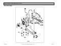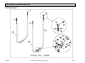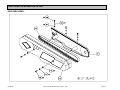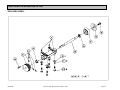
1
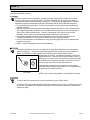
MK-5005S
BLOCK SAW
OWNER’S MANUAL &
OPERATING INSTRUCTIONS
CAUTION:
Read all safety and
operating instructions
before using this
equipment
Enter the Serial Number of your new saw in the
space below. The Serial Number is located on the
left side of the blade guard.
SERIAL NUMBER:
NOTE:
For your (1) one year warranty to be effective,
complete the warranty card (including the Serial
Number) and mail it in as soon as possible.
INTRODUCTION
We at MK Diamond want to congratulate you on selecting the MK-5005S Block Saw. We are certain that you
will be pleased with your purchase. MK Diamond takes pride in producing the finest products in the industry.
Operated correctly, your MK-5005S should provide you with years of quality service. In order to help you, we
have included this manual. This owners manual contains information necessary to operate and maintain your
MK-5005S safely and correctly. Please take a few minutes to familiarize yourself with the MK-5005S by
reading and reviewing this manual.
If you should have questions concerning your MK-5005S, please feel free to call our friendly customer service
department at: 800 421-5830
MK-5005S
Revision 07/04, Effective Date August 1, 2004
Page 2
TABLE OF CONTENTS
Page
SAFETY:
Safety Messages
Damage Prevention Message
General Safety Precautions and Hazard Symbols
California Proposition 65 Message
Electrical Requirements and Grounding Instructions
Safety Label Locations
Brick Saw Specific Warnings
Product Specifications
4
4
4
6
7
9
9
10
UNPACKING AND ASSEMBLY
Unpacking
Contents
Transport
Assembly
11
11
11
12
SETUP, ADJUSTMENT AND OPERATION
Setup
Adjustment and Operation
Cleanup
14
17
24
MAINTENANCE AND TROUBLESHOOTING
Maintenance
Troubleshooting
25
33
EXPLODED VIEW AND PARTS LIST
Exploded View
Parts List
37-46
47-51
THEORY
Theory of Diamond Blades
52
ACCESSORIES, ORDERING and RETURN INSTRUCTIONS
Accessories
Ordering Information
Return Material Policy
Packaging Instructions
Authorized Service Centers
53
54
54
54
54
Manual Part No. 158769
MK-5005S
Revision 06/04
Revision 07/04, Effective Date August 1, 2004
Page 3
SAFETY
Read and follow all safety, operating and maintenance instructions. Failure to read and follow these
instructions could result in injury or death to you or others. Failure to read and follow these instructions could
also result in damage and/or reduced equipment life.
SAFETY MESSAGES:
Safety messages inform the user about potential hazards that could lead to injury, death and/or equipment
damage. Each safety message will be preceded by one of the following (3) three words that identify the
severity of the message.
Not following instructions WILL lead to DEATH or SERIOUS INJURY
Not following instructions COULD lead to DEATH or SERIOUS INJURY
Not following instructions CAN lead to injury
DAMAGE PREVENTION AND INFORMATION MESSAGES:
A Damage Prevention Message is to inform the user of important information and/or instructions that could
lead to equipment or other property damage if not followed. Information Messages convey information that
pertains to the equipment being used. Each message will be preceded by the word NOTE, as in the example
below.
NOTE: Equipment and/or property damage may result if these instructions are not followed.
GENERAL SAFETY PRECAUTIONS AND HAZARD SYMBOLS:
In order to prevent injury, the following safety precautions and symbols should be followed at all times!
Safety Precautions:
KEEP GUARDS IN PLACE.
In order to prevent injury, keep guards in place and in working order at all times.
REMOVE ADJUSTING KEYS AND WRENCHES.
Form a habit of checking to see that keys and adjusting wrenches are removed from the power tool before it
is turned on.
KEEP WORK AREA CLEAN.
Cluttered work areas and benches invite accidents.
DO NOT USE IN DANGEROUS ENVIRONMENTS.
Do not use power tools in damp or wet locations nor expose them to rain. Always keep the work area well
lighted.
KEEP CHILDREN AWAY.
All visitors and children should be kept a safe distance from work area.
MAKE THE WORKSHOP KID PROOF.
Make the workshops kid proof by using padlocks, master switches or by removing starter keys.
DO NOT FORCE THE TOOL.
A power tool will do a job better and safer operating at the rate for which it was designed.
USE THE RIGHT TOOL.
Do not force a tool or an attachment, to do a job that it was not designed to do.
MK-5005S
Revision 07/04, Effective Date August 1, 2004
Page 4
SAFETY
USE THE PROPER EXTENSION CORD.
If using an extension cord make sure it is in good condition first. When using an extension cord, be sure to
use one heavy enough to carry the current your product will draw. An undersized cord will cause a drop in
line voltage that will result in a loss of power and overheating. TABLE 1, Page 7 shows the correct AWG
size to use depending on cord length and nameplate ampere rating. If in doubt, use the next heavier gage.
The smaller the gage number, the heavier the cord.
WEAR PROPER APPAREL.
Do not wear loose clothing, gloves, neckties, rings, bracelets, or other jewelry that may be caught in moving
parts. Non-slip footwear is recommended. Wear protective hair covering to contain long hair.
ALWAYS USE SAFETY GLASSES.
Safety glasses should always be worn when working around power tools. In addition, a face,
dust mask or respirator should be worn if a cutting operation is dusty. Everyday eyeglasses only
have impact resistant lenses and may not prevent eye injury - they are NOT safety glasses.
SECURE WORK.
Clamps or a vise should be used to hold work whenever practical. Keeping your hands free to operate a
power tool is safer.
DO NOT OVERREACH.
Keep proper footing and balance at all times by not overreaching.
MAINTAIN TOOLS WITH CARE.
Keep tools clean for the best and safest performance. Always follow maintenance instructions for
lubricating, and when changing accessories.
DISCONNECT TOOLS.
Power tools should always be disconnected before servicing or when changing accessories, such as blades,
bits, cutters, and the like.
REDUCE THE RISK OF UNINTENTIONAL STARTING.
on
Make sure the ON/OFF Switch is in the OFF position before plugging in a power tool.
USE RECOMMENDED ACCESSORIES.
Consult the owner's manual for recommended accessories. Using improper accessories may increase the
risk of personal or by-stander injury.
NEVER STAND ON THE TOOL.
Serious injury could occur if a power tool is tipped, or if a cutting tool is unintentionally contacted.
CHECK FOR DAMAGED PARTS.
Before using a power tool, check for damaged parts. A guard or any other part that is damaged should be
carefully checked to determine it would operate properly and perform its intended function. Always check
moving parts for proper alignment or binding. Check for broken parts and mountings and all other conditions
that may affect the operation of the power tool. A guard, or any damaged part, should be properly repaired
or replaced.
DIRECTION OF FEED.
Always feed work into a blade or cutter against the direction of rotation. A blade or cutter should always be
installed such that rotation is in the direction of the arrow imprinted on the side of the blade or cutter.
NEVER LEAVE A TOOL RUNNING UNATTENDED – TURN POWER OFF.
Do not leave a tool until it comes to a complete stop. Always turn a power tool OFF when leaving the work
area, or, when a cut is finished.
MK-5005S
Revision 07/04, Effective Date August 1, 2004
Page 5
SAFETY
Hazard Symbols:
ELECTRICAL SHOCK!
Never touch electrical wires or components while the motor is running. Exposed, frayed or worn
electrical motor wiring can be sources of electrical shock that could cause severe injury or burns.
ACCIDENTAL STARTS!
on
Before plugging the equipment into an electrical outlet, be sure the On/Off Switch is in the OFF
position to prevent accidental starting. Unplug the power tool before performing any service operation.
ROTATING OR MOVING PARTS!
Keep hands, feet, hair, and clothing away from all moving parts to prevent injury. Never operate a
power tool with covers, shrouds, or guards removed.
Sawing and drilling generates dust. Excessive airborne particles may cause irritation to eyes, skin and
respiratory tract. To avoid breathing impairment, always employ dust controls and protection suitable to the
material being sawed or drilled; See OSHA (29 CFR Part 1910.1200). Diamond Blades improperly used are
dangerous. Comply with American National Standards Institute Safety Code, B7.1 and, Occupational Safety
and Health Act covering Speed, Safety Guards, Flanges, Mounting Procedures, General Operating Rules,
Handling, Storage and General Machine Conditions.
CALIFORNIA PROPOSITION 65 MESSAGE:
Some dust created by power sanding, sawing, grinding, drilling, and other construction activities contain
chemicals known [to the State of California] to cause cancer, birth defects or other reproductive harm. Some
examples of these chemicals are:
• Lead, from lead-based paints
• Crystalline silica, from bricks and cement and other masonry products and
• Arsenic and chromium, from chemically treated lumber
For further information, consult the following sources:
http://www.osha-slc.gov/sltc/silicarystalline/index.html
http://www.oehha.org/prop65/out_of_date/6022kLstA.html
Your risk from these exposures varies depending on how often you do this type of work. To reduce your
exposure to these chemicals, work in a well-ventilated area, and work with approved safety equipment, such
as those dust masks that are specially designed to filter out microscopic particles.
MK-5005S
Revision 07/04, Effective Date August 1, 2004
Page 6
SAFETY
ELECTRICAL REQUIREMENTS AND GROUNDING INSTRUCTIONS:
In order to prevent potential electrical shock and injury, the following electrical safety precautions and symbols
should be followed at all times!
In case of a malfunction or breakdown, grounding provides a path of least resistance for electric
current to reduce the risk of electric shock. This tool is equipped with an electric cord having an
equipment-grounding conductor and a grounding plug. The plug must be plugged into a matching
outlet that is properly installed and grounded in accordance with all local codes and ordinances.
• Do not modify the plug provided – if it will not fit the outlet; have the proper outlet installed by a
qualified electrician
• Improper connections of the equipment-grounding conductor can result in a risk of electric shock.
The equipment-grounding conductor is the insulated conductor that has an outer surface that is
green, with or without yellow stripes. If repair or replacement of the electric cord or plug is
necessary, do not connect the equipment-grounding conductor to a live terminal
• Check with a qualified electrician or service personnel if the grounding instructions are not
completely understood, or if in doubt as to whether the tool is properly grounded
• Use only 3-wire extension cords that have 3-prong grounding plugs and 3-pole receptacles that
accept the tool's plug
• Repair or replace a damaged or worn cord immediately
This tool is intended for use on a circuit that has an outlet that looks similar to the one shown in
Sketch B of Figure 1. The tool has a grounding plug that looks similar to the plug illustrated in
Sketch A of FIGURE 1. Make sure the tool is connected to an outlet having the same
configuration as the plug. No adapter is available or should be
used with this tool. If the tool must be reconnected for use on a
different type of electric circuit, the reconnection should be made
by qualified service personnel; and after reconnection, the tool
should comply with all local codes and ordinances.
(B)
(A)
FIGURE 1
If permanently connected, this tool should be connected to a
grounded metal permanent wiring system; or to a system having
an equipment-grounding conductor.
NOTE: Use of a temporary adapter is not permitted in Canada.
To reduce the risk of electrocution, keep all connections dry and off the ground.
A Ground Fault Circuit Interrupter (GFCI) should be provided on the circuit(s) or outlet(s) to be used
for the Saw. Receptacles are available having built-in GFCI protections and may be used for this
measure of safety.
MK-5005S
Revision 07/04, Effective Date August 1, 2004
Page 7
SAFETY
To avoid the possibility of the appliance plug or receptacle getting wet, position the Block Saw to
one side of a wall mounted receptacle. This will prevent water from dripping onto the receptacle or
plug. A "drip loop," shown in FIGURE 2, should be arranged by the user to properly position the
power cord relative to the power source.
The "drip loop" is that part of the cord below the level of the receptacle, or
Motor
the connector, if an extension cord is used. This method of positioning the
Power
Saw
cord prevents the travel of water along the power cord and coming in
Cord
contact with the receptacle.
Drip
If the plug or receptacle gets wet, DO NOT unplug the cord. Disconnect
Loop
the fuse or circuit breaker that supplies power to the tool. Then unplug and
examine for presence of water in the receptacle.
Floor
FIGURE 2
Use only extensions cords that are intended for outdoor use. These extension cords are identified
by a marking "Acceptable for use with outdoor appliances; store indoors while not in use." Use only
extension cords having an electrical rating not less than the rating of the product. Do not use
damaged extension cords. Examine extension cords before using and replace if damaged. Do not
abuse extension cords and do not yank on any cord to disconnect. Keep cords away from heat and
sharp edges. Always disconnect the extension cord from the receptacle before disconnection the
product form the extension cord.
To reduce the risk of electrocution, keep all connections dry and off the ground. Do not touch the
plug with wet hands.
Use of undersize extension cords result in low voltage to the motor that can result in motor burnout
and premature failure. MK Diamond warns that equipment returned to us showing signs of being run
in a low voltage condition, through the use of undersized extension cords will be repaired or replaced
totally at the customers expense. There will be no warranty claim.
To choose the proper extension cord,
• Locate the length of extension cord needed in TABLE 1 below.
• Once the proper length is found, move down the column to obtain the correct AWG size required
for that length of extension cord.
Extension Cord Minimum Gage for Length
Volts
240V
MK-5005S
Total Length of Cord in Feet
25 ft. (7.5 m)
50 ft. (15 m)
75 ft (23 m)
AWG
AWG
AWG
10
10
8
TABLE 1
Revision 07/04, Effective Date August 1, 2004
Page 8
SAFETY
SAFETY LABEL LOCATIONS:
Safety labels are located according to Figures 1 to 7 below. The labels contain important safety information.
Please read the information contained on each safety label. These labels are considered a permanent part of
your saw. If a label comes off or becomes hard to read, contact MK Diamond or your dealer for a
replacement.
Item
1A.
1B.
1C.
2.
3.
4A.
4B.
4C.
5A.
5B.
6.
7.
Location
Motor Front
Motor Front
Motor Front
Motor Left Side
Motor Right Side
Saw and Motor Rear
Saw and Motor Rear
Saw and Motor Rear
Blade Guard
Blade Guard
Pump Rear
Pump Bottom
Description
Grounding Requirements
Motor Overload Instructions
Warning – General Requirements
Caution – Pump Receptacle Requirements
Motor Label Plate
Caution – Specific Operating Requirements
Service Or Warranty Instructions
Warning – Extension Cord Requirements
MK Diamond Serial Number
Caution – Personal Protection Requirements
Pump Label Plate
Warning – Pump Operating Warning
Part No.
N/A
N/A
155806
N/A
N/A
155576
155038
155672
N/A
155040
N/A
N/A
B
A
1
B
3
2
C
C
A
B
A
4
5
6
7
BRICK SAW SPECIFIC WARNINGS:
Read Owners Manual
Wear Protective Gear for –
•
•
•
•
MK-5005S
Head
Lungs
Ear
Eye
Revision 07/04, Effective Date August 1, 2004
Page 9
SAFETY
PRODUCT SPECIFICATIONS:
The MK-5005S is a versatile masonry saw. Operated and used according to this manual, the MK-5005S will
provide years of dependable service.
General Description:
The MK-5005S, is engineered as a 20" saw, consisting of a powerful 230v single phase motor. The saw is
capable of cutting brick and masonry up to 8" x 8" x 16" in size in a single pass.
Motor and Weight Specifications:
Motor and Weight specifications for the MK-5005S are listed in Table 2 below.
Voltage
Amperage
Frequency
RPM
Weight
230v
23A
50 Hz
2850 rpm
445 lbs.*
Table 2
60 Hz
3,450
Blade Capacity:
The MK-5005S uses a 20-inch diameter segmented MK Diamond blade with a .125-inch cutting width.
Masonry Types:
The MK-5005S can cut a variety of masonry types including, cinder block, slump stone block, wall brick, paver
brick, concrete block and cylinders, roofing tile, marble, granite, decorative rock or almost any other nonferrous material.
NOTE:
The MK-5005S is not designed to cut plastic or ferrous (metals) material.
Peddle Assisted Cutting Head:
The MK-5005S is designed with a peddle assisted Cutting Head to allow the operator to use both hands when
cutting. The Cutting Head can be raised or lowered by the use of an adjusting wheel to set the start of the
cut.
*Without Movable Cutting Table
MK-5005S
Revision 07/04, Effective Date August 1, 2004
Page 10
UNPACKING, TRANSPORT and ASSEMBLY
UNPACKING:
Your MK-5005S has been shipped from the factory thoroughly inspected. Only minimal assembly is required.
If not already done, remove the MK-5005S from the pallet and place it on a flat surface using a forklift.
Remove the Accessories from the water basin and place along side the MK-5005S (Owners Manual is in
Accessories Packet).
CONTENTS:
In the containers, you will find one (1) MK-5005S, one (1) movable cutting table, one (1) adjustable cutting
guide, one (1) electric water pump, one (1) pump discharge fitting, one (1) blade wrench, one (1) drain plug,
one (1) owner's manual, one (1) pump manual and one (1) warranty card.
MK-5005S
Movable Cutting
Table
Adjustable
Cutting Guide
Electric
Water Pump
Pump
Discharge Fitting
Blade
Wrench
Drain
Plug
Owner's
Manual
Pump
Manual
Warranty
Card
TRANSPORT:
The MK-5005S weighs approximately forty (445) pounds (Without the Movable Cutting Table).
Do not attempt to move the MK-5005S without a forklift.
NOTE: Place the Cutting Head in the DOWN position, and remove the Movable Cutting Table when
transporting the MK-5005S.
Due to its solid construction, the MK-5005S may only be transported with a forklift. Position the cutting head
in the DOWN position, remove the Movable Cutting Table, and transport the saw using the 8 lift points
positioned strategically around the base. Use tie downs when transporting the saw.
Tie
Down
Lift Point
MK-5005S
Revision 07/04, Effective Date August 1, 2004
Page 11
UNPACKING, TRANSPORT and ASSEMBLY
ASSEMBLY:
Follow the assembly instructions to prepare your MK-5005S for operation.
1. Movable Cutting Table Installation:
Guide Rails
Roller Wheels
Cutting Table
Front
Guide Rail
(A)
Position Movable Cutting Table
Verify ease of movement
(See Maintenance Section
If Problems Arise)
Roller Wheels
(B)
Seat all four Roller Wheels on
the Guide Rails
(C)
Verify Correct Seating
2. Adjustable Cutting Guide Installation:
Turn counterclockwise to loosen
Align
Parallel Slots
Turn clockwise to tighten
Seated
Ruler/Stop
(B)
Align the Adjustable Cutting
Guide above the Movable
Cutting Table Ruler/Stop
(A)
Loosen the Thumbscrew
(C)
Seat the Adjustable Cutting
Guide and tighten the
retaining thumbscrew
3. Diamond Blade Installation:
NOTE: When installing the Retaining Screw, do not “cross-thread" and DO NOT over tighten the screw.
Diamond Blade
Turn counterclockwise to
loosen
Turn clockwise to
raise Cutting Head
(A)
Raise the Cutting Head
MK-5005S
Blade
Wrench
Retaining Screw
and Outer Flange
(B)
Identify and remove the
Retaining Screw and
Outer Flange
Revision 07/04, Effective Date August 1, 2004
(C)
Install the Diamond Blade
onto the Blade Shaft
Page 12
UNPACKING, TRANSPORT and ASSEMBLY
Rotate Blade
Wrench clockwise
to tighten
Rotation Arrow
Facing out
Retaining
Screw and
Outer Flange
Rotation Direction
(D)
Verify the Blade is seated on
the Blade Shaft and direction
of rotation is correct
(E)
Install Retaining Screw and
Outer Flange, then tighten
4. Water Pump Preperation:
Turn clockwise
to tighten
Cooling
Transfer
Tube
Discharge
Fitting
(A)
Install Water Pump
Discharge Fitting
MK-5005S
Press on
(B)
Press the end of the Cooling
Transfer Tube onto the Water
Pump Discharge Fitting
Revision 07/04, Effective Date August 1, 2004
Page 13
SETUP, ADJUSTMENT and OPERATION
SETUP:
•
•
•
Before powering or starting, check for damage that could prevent this equipment from proper operation or
performing its intended function. Check for binding and alignment of moving parts. Check for damaged,
broken, or missing parts.
Verify the ON/OFF switch is in the OFF position.
Before connecting the MK-5005S to a power supply, be sure the voltage, cycle and phase of the job site
power source meet the requirements of TABLE 3
VOLTAGE:
CYCLE:
PHASE:
•
•
•
230v
50/60hz
Single phase
TABLE 3
If using an extension power cord, make sure the length and wire gauge corresponds to the requirements
listed in TABLE 1 on page 7. An extension power cord that is too small in wire gauge (diameter), or too
long in length, will cause the motor to overheat and could cause premature failure.
Use an approved Ground Fault Circuit Interrupter (GFCI)
Do not cover the motor vents as this could lead to motor overheating.
1. Pre-start Inspection:
The pre-start inspection should be performed before beginning any job.
If the Diamond Blade shows signs of fatigue cracking, replace the blade before starting work.
NOTE: In order to avoid breaker tripping, a 30-amp circuit breaker should be used.
ON/OFF
Switch
Off
Position
(A)
Ensure the ON/OFF Switch
is in the OFF position
Replace if excessively grooved
(See Maintenance Section)
Cracks
Inspect for cracks,
cuts and frays
(B)
Check all electrical connections
(C)
Inspect the Blade for damage
and verify it’s correct for the
material being cut
Verify ease of movement
(See Maintenance Section)
Tighten or replace
loose hardware
Inspect for
damage
(D)
Inspect Wooden Strip for
excessive grooves
MK-5005S
(E)
Verify Movable Cutting Table
moves freely
Revision 07/04, Effective Date August 1, 2004
(F)
Inspect the MK-5005S for general
damage and/or loose hardware
Page 14
SETUP, ADJUSTMENT and OPERATION
Inspect for
cracks or cuts
Inspect for
damage
(D)
Inspect the Pump Assembly
for damage – ensure the cord
is free of cracks or cuts
2. Connecting the Water Pump:
1.
2.
To prevent the possibility electrical shock, the MK-5005S MUST be de-energized when
connecting the Water Pump.
To prevent the possibility of electrical shock, use only MK Diamond qualified replacement
parts
NOTE: To prevent pump damage, the Water Pump must be disconnected if cutting with a Dry Blade.
ON/OFF
Switch
Pump
Connection
Off
Position
Install
(A)
Ensure the ON/OFF Switch
is in the OFF position
MK-5005S
(B)
Connect the Water Pump power
cord to the connection found on
the side of the motor
Revision 07/04, Effective Date August 1, 2004
Page 15
SETUP, ADJUSTMENT and OPERATION
3. Water Pump Setup for Operation:
The Water Pump can be setup for operation in two ways, External Water Source or Re-circulation.
NOTE: If using a dry blade for operation, DO NOT connect the water pump.
I. External Water Source:
This is the preferred method of cooling. This method may add as much as 20 percent to the life of the blade.
Drain Plug
Place Water Pump
in container
Cover Pump
Intake
External
Container
(A)
Remove the Drain plug
(B)
Place the Water Pump
in an external container
(C)
Fill the external container until
water completely covers the
Water Pump intake
NOTE: Follow all applicable Federal, State and Local laws for the proper disposal of wastewater.
External
Drain Line
Drain
Connection
(D)
Locate the Water Basin
Drain Connection (located in
the back of the water basin)
(E)
Install an external drain line
onto the Drain Connection
II. Re-circulation:
NOTE: When using the re-circulation method, the water should be changed often for longer pump life.
Drain Plug
Installed
Water
Pump
(A)
Ensure the Drain Plug is
installed in the Water Basin
MK-5005S
(B)
Place the Water Pump in the
back of the Water Basin
Revision 07/04, Effective Date August 1, 2004
Cover Pump
Intake
(C)
Fill the Water Basin until water
completely covers the
Water Pump intake
Page 16
SETUP, ADJUSTMENT and OPERATION
ADJUSTMENT AND OPERATION:
1. Power Connection:
ON/OFF
Switch
Off
Position
(A)
Ensure the ON/OFF Switch
is in the OFF position
(B)
Connect the MK-5005S to the
proper power source
2. Cutting Setup:
NOTES
1. While the MK-5005S can cut the materials listed earlier in this document, it is specifically
designed to cut concrete masonry. Cutting another material with the MK-5005S will reduce the
life of the diamond blade.
2. Due to the material being cut, the diamond blade should not require dressing. If dressing is
required, use a soft stone such as sandstone.
Set edge of Cutting
Guide to desired cut
length on Ruler/Stop
Ruler/Stop
Ruler Markings
(A)
Set Adjustable Cutting Guide
Set material against
Adjustable Cutting
Guide and Ruler/Stop
Adjustable
Cutting Guide
Ruler/Stop
(B)
Position Masonry Piece
DO NOT FORCE the blade to cut, it will do the job better and safer at rate for which it was
designed.
MK-5005S
Revision 07/04, Effective Date August 1, 2004
Page 17
SETUP, ADJUSTMENT and OPERATION
3. Step Cuts:
A Step Cut is performed when a series of small cuts of increasing depth are used to complete a single cut.
NOTE: 1. Step Cutting is the preferred cutting method for all cuts.
2. When cutting hard material Step Cutting should always be used.
3. Step Cutting will extend the life of the Diamond Blade.
ON/OFF
Switch
Direction of
Movement
On
Position
Hold Work
in Position
Control Valve
(A)
(B)
(C)
Step Cut Setup
Turn the motor ON
Open the Cooling Flow Control
(Adjust the height of the Cutting
Valve and adjust flow
Head as necessary)
DO NOT FORCE TOOL, it will do the job better and safer at the rate for which it was designed.
Lower Cutting
Head 1/4 -1/2
Inch during
Push Stroke
Cooling Flow
Points
Push Direction
(D)
Verify proper cooling flow on
both sides of the blade
Repeat “Push”
and “Pull” Strokes
Until Cut Complete
(G)
Repeat Steps E and F
Until Cut Complete
MK-5005S
Pull Direction
(E)
Step Cut “Push” Stroke
ON/OFF
Switch
Lower Cutting
Head an additional
1/4 -1/2 Inch during
Pull Stroke
(F)
Step Cut “Pull” Stroke
Off
Position
(H)
Turn the saw off when
work is complete
Revision 07/04, Effective Date August 1, 2004
Page 18
SETUP, ADJUSTMENT and OPERATION
4. Chop Cutting:
A Chop Cut is performed by cutting completely through an object in one pass.
Position
work below
Cutting Head
ON/OFF
Switch
On
Position
Direction of
movement
Control Valve
(A)
Chop Cut Setup
(Adjust the height of the Cutting
Head as necessary)
(B)
Turn the motor ON
(C)
Open the Cooling Flow Control
Valve and adjust flow
DO NOT FORCE TOOL, it will do the job better and safer at the rate for which it was designed.
Hold the Movable
Cutting Table
stationery
Lower Cutting
Head smoothly
to cut
Cooling Flow
Points
(D)
Verify proper cooling flow on
both sides of the blade
ON/OFF
Switch
Continue to lower
Cutting Head until
cut complete
(E)
Lower Cutting Head
to Begin Cutting
(F)
Continue Lowering Head
until Cut Complete
Off
Position
(G)
Turn the saw off when
work is complete
MK-5005S
Revision 07/04, Effective Date August 1, 2004
Page 19
SETUP, ADJUSTMENT and OPERATION
5. Cutting with the Cutting Head Positioned Down:
This method is preferred when cutting small objects.
ON/OFF
Switch
Lower Cutting
Head until just
above table
Hold Work
in Position
Turn counterclockwise to lower
(A)
Lower the Cutting Head until the
blade is just off the surface of the
Movable Cutting Table
On
Position
(B)
Set masonry piece
in position
(C)
Turn the motor ON
DO NOT FORCE TOOL, it will do the job better and safer at the rate for which it was designed.
Direction of
Movement
Cooling Flow
Points
Control Valve
(D)
Open the Cooling Flow Control
Valve and adjust flow
Allow Blade to
stop before
removing work
Push Slowly to Cut
(E)
Verify proper cooling flow on
both sides of the
ON/OFF
Switch
(F)
Slowly push piece toward Blade
to begin the cut
Off
Position
Continue to Push
until Cut Complete
(G)
Continue pushing Piece into
Blade until cut complete
MK-5005S
(H)
Turn the saw off when
work is complete
Revision 07/04, Effective Date August 1, 2004
Page 20
SETUP, ADJUSTMENT and OPERATION
6. Cutting with the Piece Position Vertically:
This method may be used when "notching” the masonry piece.
Set against Adjustable
Cutting Guide and
Ruler/Stop
ON/OFF
Switch
Direction of
Movement
On
Position
Control Valve
(A)
Position Masonry Piece
(Adjust the height of the Cutting
Head as necessary)
(B)
Turn the motor ON
(C)
Open the Cooling Flow Control
Valve and adjust flow
DO NOT FORCE TOOL, it will do the job better and safer at the rate for which it was designed.
Allow Blade to
stop before
removing work
Cooling Flow
Points
Push Slowly to Cut
(D)
Verify proper cooling flow on
both sides of the
ON/OFF
Switch
(E)
Slowly push piece toward Blade
to begin the cut
Continue to Push
until Cut Complete
(F)
Continue pushing piece into
Blade until cut complete
Off
Position
(G)
Turn the saw off when
work is complete
MK-5005S
Revision 07/04, Effective Date August 1, 2004
Page 21
SETUP, ADJUSTMENT and OPERATION
7. Angle Cuts:
Angle Cuts may be performed using the Step Cut, Chop Cut, Cutting Head Positioned Down methods or with
the masonry piece positioned vertically. The following example utilizes the Step Cut method.
Turn to counterclockwise to loosen
Align 45° Slots
to Ruler/Stop
Remove Adjustable
Cutting Guide
Ruler/Stop
(B)
Reposition Adjustable
Cutting Guide
(A)
Remove Adjustable
Cutting Guide
ON/OFF
Switch
On
Position
Set against Adjustable
Cutting Guide and
Ruler/Stop
Adjustable
Cutting Guide
(C)
Position the Masonry piece
(Adjust Cutting Head)
Direction of
Movement
Cooling Flow
Points
Control Valve
(E)
Open the Cooling Flow Control
Valve and adjust flow
(D)
Turn the motor ON
Ruler/Stop
(F)
Verify proper cooling flow on
both sides of the blade
DO NOT FORCE TOOL, it will do the job better and safer at the rate for which it was designed.
Lower Cutting
Head 1/4 -1/2
Inch during
Push Stroke
Push Direction
Repeat “Push”
and “Pull” Strokes
until cut complete
Pull Direction
(G)
Step Cut “Push” Stroke
ON/OFF
Switch
Lower Cutting
Head an additional
1/4 -1/2 Inch during
the Pull Stroke
(H)
Step Cut “Pull” Stroke
(I)
Repeat Steps G and H
until cut complete
Off
Position
(J)
Turn the saw off when
work is complete
MK-5005S
Revision 07/04, Effective Date August 1, 2004
Page 22
SETUP, ADJUSTMENT and OPERATION
8. Cutting using the Foot Pedal:
The Foot Peddle may be used to Step Cut, Chop Cut, cut with the Cutting Head Positioned Down, or with the
masonry piece positioned vertically. Using the Foot Peddle frees both of the operator's hands for holding the
masonry piece. The following example utilizes the Step Cut method.
Set masonry against
the Adjustable Cutting
Guide and Ruler/Stop
ON/OFF
Switch
On
Position
Direction of
Movement
Control Valve
(A)
Position Masonry piece
(Adjust the height of the Cutting
Head as necessary)
(B)
Turn the motor ON
(C)
Open the Cooling Flow Control
Valve and adjust flow
DO NOT FORCE TOOL, it will do the job better and safer at the rate for which it was designed.
Lower Cutting
Head 1/4 -1/2
Inch during
Push Stroke
Cooling Flow
Points
Pull Direction
Push Direction
(D)
Verify proper cooling flow on
both sides of the blade
(E)
Step Cut “Push” Stroke
ON/OFF
Switch
Lower Cutting
Head an additional
1/4 -1/2 Inch during
Pull Stroke
(F)
Step Cut “Pull” Stroke
Off
Position
Repeat “Push”
and “Pull” Strokes
Until Cut Complete
(G)
Repeat Steps E and F
until cut complete
MK-5005S
(H)
Turn the saw off when
work is complete
Revision 07/04, Effective Date August 1, 2004
Page 23
SETUP, ADJUSTMENT and OPERATION
9. Cleanup:
Pump
Suction
Water Pump
In container
External
Container
(A)
Clean the Water Pump
suction of all debris
ON/OFF
Switch
(B)
Place the Water Pump
in an external container
Cooling Flow
Points
(C)
Run the saw until clear
water is seen at the blade
cooling ports (Approx. 1 minute)
Off
Position
Soap and
clean water
(D)
Ensure the ON/OFF Switch
is in the OFF position
(E)
Unplug MK-5005S from the
power source
(F)
Clean the saw with
soap and clean water
Clean
Guide Rails
Clean
Water Basin
Clean Roller
Wheels
(H)
Clean the Movable Cutting
Table Guide Rails
(G)
Clean the Water Basin
(I)
Clean the Movable Cutting
Table Roller Wheels
Clean
Springs
(J)
Clean the Movable Cutting Table
Roller Wheel Frame Support
MK-5005S
(K)
Clean the remainder of the saw
Revision 07/04, Effective Date August 1, 2004
Page 24
MAINTENANCE AND TROUBLESHOOTING
MAINTENANCE:
1. New Maintenance:
Perform the following after initial purchase and operation of the MK-5005S.
Inspect
V-belt
(A)
Check and adjust V-belt
tension Following 1st 48 hours of
operation (See V-belt Inspection)
2. Maintenance Following Use:
The following maintenance should be performed following each use. Use Light oil, such as WD-40 or 3 in 1
when lubricating parts.
ON/OFF
Switch
Off
Position
(A)
Ensure the ON/OFF Switch
is in the OFF position
Lubricate
pivot points
(B)
Lubricate lower pivot points
Lubricate
Springs
(D)
Lubricate all spring assemblies
MK-5005S
Lubricate
pivot points
(C)
Lubricate upper pivot points
Roller Wheel
Assembly
(E)
Lubricate the Roller
Wheel Assemblies
Revision 07/04, Effective Date August 1, 2004
Page 25
MAINTENANCE AND TROUBLESHOOTING
3. Monthly Maintenance:
The following should be performed monthly. Items should be lubricated as directed.
Inner
Flange
Rotate Blade Wrench
counter-clockwise
to loosen
Retaining
Screw and
Outer Flange
(A)
Remove the Diamond Blade
Verify
Tight
Outer
Flange
(B)
Clean and Lubricate the Outer
Flange and Retaining-bolt
Verify Bolts
Tight
(E)
Verify the motor Adjustment
Strap is tight
(D)
Verify the Roller Wheel
Assemblies are tight and
in good condition
(C)
Clean and Lubricate the
Inner Flange
Verify four
bolts tight
(F)
Verify all motor mounting
bolts are tight
Lubricate Zerk
Fittings
(G)
Apply grease to the 9 Zerk
Fittings of the MK-5005S
(See Unit Lubrication)
MK-5005S
Revision 07/04, Effective Date August 1, 2004
Page 26
MAINTENANCE AND TROUBLESHOOTING
4. Diamond Blade Change-out:
Disconnect the tool before servicing and when changing accessories, such as blades, bits,
cutters, and the like.
Turn counterclockwise to
loosen
Turn clockwise to
raise Cutting Head
Blade
Wrench
Diamond Blade
Retaining Screw
and Outer Flange
(B)
Identify and remove the
Retaining Screw and
Outer Flange
(A)
Raise the Cutting Head
Diamond Blade
Rotation Arrow
Facing out
Rotate Blade
Wrench clockwise
to tighten
Rotation Direction
(C)
Install the new Diamond
Blade onto the Blade Shaft
MK-5005S
(C)
Remove the Diamond Blade
from the Blade Shaft
(D)
Verify the Blade is seated on
the Blade Shaft and direction
of rotation is correct
Revision 07/04, Effective Date August 1, 2004
Retaining
Screw and
Outer Flange
(E)
Install Retaining Screw and
Outer Flange, then tighten
Page 27
MAINTENANCE AND TROUBLESHOOTING
5. MK-5005S Lubrication Points:
Use standard grease when lubricating the MK-5005S. Clean the Zerk fitting when finished lubricating.
Apply grease slowly; stop when grease is seen between joints.
Lubrication
Point
(A)
Rear Blade Guard Stay-level
pivot point, lubrication point
Lubrication
Points
(D)
Front and Rear Connecting
Arms, right side (from front),
lubrication points
Lubrication
Point
(B)
Front Blade Guard Stay-level
pivot point, lubrication point
Lubrication
Points
(C)
Front and Rear Connecting
Arms, left side (from front),
lubrication points
Lubrication
Point
Lubrication
Points
(E)
Elevation Pivot Bracket, Pivot
Shaft Housing, lubrication point
(F)
Cutting Head Rear Connecting
Arm, lubrication point
Lubrication
Points
Lubrication
Point
Lubrication
Points
(G)
Crank Wheel Assembly Bearing,
lubrication point
MK-5005S
(H)
Depth Control Screw Housing,
lubrication point
Revision 07/04, Effective Date August 1, 2004
(I)
Motor Bearing lubrication points
Page 28
MAINTENANCE AND TROUBLESHOOTING
6. Movable Cutting Table Wheel Change Out:
NOTE: All four (4) Movable Cutting Table, Roller Wheels should be replaced at the same time (MK Diamond
Part No. – 152493).
Rotate counterclockwise to loosen
Verify
Tight
1/2-Inch Wrench
(A)
Place Movable Cutting Table on
workbench with Roller Wheels Up
(B)
Remove Roller Wheels
Clean Holes
(C)
Prepare for installation of new
Roller Wheels
NOTE: When installing the Retaining Bolt, do not “cross-thread" and DO NOT over tighten the Nut.
Roller Wheel
Assembly
Rotate clockwise
to tighten
1/2-Inch Wrench
(D)
Obtain Wheel replacement parts
(See parts list)
Lubricate with
Light Oil (WD-40,
3 in 1, etc)
(F)
Lubricate Roller Wheels
MK-5005S
(E)
Install Wheel/Washer Assembly
into Movable Cutting Table
(F)
Install Roller Wheel
Retaining Nut and tighten
Install Movable Cutting
Table (See Setup,
Adjustment and Operation)
(G)
Install Movable Cutting Table
Revision 07/04, Effective Date August 1, 2004
Page 29
MAINTENANCE AND TROUBLESHOOTING
7. Protective Wooden Strip Replacement:
The protective wooden strip is to protect the Movable Cutting Table from damage during operation. Over
time, the wooden strip will become grooved from use. A grooved wooden strip will not support masonry
during cutting causing the blade to "break through" the piece instead of performing a smooth cut (MK
Diamond Part No. – 157748).
Protective
Wooden Strip
Phillips
Screwdriver
Retaining Screw
(A)
Inspect the Wooden Strip for
excessive wear and grooves
(B)
Place Movable Cutting Table on
a work bench with the wheels up
Phillips
Screwdriver
Wooden
Strip
(D)
Replace worn
Protective Wooden Strip
MK-5005S
(C)
Remove the two Protective
Wooden Strip retaining screws
Install Movable Cutting
Table (See Setup,
Adjustment and Operation)
Retaining Screw
(E)
Place Movable Cutting Table on
a work bench with the wheels up,
and reinstall retaining screws
Revision 07/04, Effective Date August 1, 2004
(F)
Install the Movable Cutting Table
Page 30
MAINTENANCE AND TROUBLESHOOTING
8. V-Belt Inspection, Adjustment and Replacement:
The MK-5005S is designed with a power transmission V-belt. In order to ensure the MK-5005S operates a
peak efficiency, the V-belt should be inspected monthly, and changed if the v-belt shows damage and/or
excessive wear.
NOTE: When a new belt is installed, it should be inspected and re-tensioned after the first forty-eight (48)
hours of operation.
ON/OFF
Switch
Off
Position
(A)
Ensure the ON/OFF Switch
is in the OFF position
Diamond
Blade
(B)
Unplug MK-5005S from the
Power Source
9/16-inch
Wrench
(C)
Remove the Diamond Blade
Inspect
V-belt
Check Tension
1/2-way
between pulleys
Rotate counterclockwise to
loosen
(D)
Remove the Belt Guard
(E)
Inspect the V-belt for cracks,
fraying, separation and wear. Go
to step G if replacement required
Rotate counterclockwise to
loosen
(G)
Loosen motor mounting bolts
If re-tensioning only, go to step N
MK-5005S
9/16-inch
Wrench
Rotate counterclockwise to
loosen
9/16-inch
Wrench
(F)
Check belt for proper tension
if tension correct, go to step R
(proper tension 1/4-inch)
(H)
Loosen the Motor Adjustment
Strap
Revision 07/04, Effective Date August 1, 2004
Direction of push
(I)
Push the motor toward the
front of the Cutting Head to
loosen the V-belt
Page 31
MAINTENANCE AND TROUBLESHOOTING
Outer V-belt
(J)
Remove the outer V-belt
Inner V-belt
(K)
Remove the inner V-belt
Belt Seated
(L)
Install 2 new V-belts
(MK Diamond Part No. 152028)
9/16-inch
Wrench
Pulley
(M)
Verify the V-belts are seated in
the grooves of both pulleys
(N)
Tighten the Motor Adjustment
Strap to remove slack
(O)
Check V-belt tension
(proper tension 1/4-inch)
Rotate clockwise
to tighten
Rotate clockwise
to tighten
9/16-inch
Wrench
(P)
Repeat steps N and O until
proper V-belt tension
is achieved
Check Tension
1/2-way
between pulleys
Rotate clockwise
to tighten
Continue Adjustment
Until Correct
MK-5005S
New V-belts
(Q)
Tighten the motor
mounting bolts
Revision 07/04, Effective Date August 1, 2004
9/16-inch
Wrench
(R)
Install the Belt Guard
Page 32
MAINTENANCE AND TROUBLESHOOTING
TROUBLESHOOTING:
1. Blade Stops Turning:
ON/OFF
Switch
Verify all plugs
connected
On
Position
If motor does not
start, go to Step C
(A)
Verify the motor ON/OFF
switch is in the ON position
(B)
Verify the MK-5005S is connected
to the Power Source
If less than 30
Amps move saw
to 30 Amp circuit
Check Breaker
30 Amps
or greater
If circuit 30 Amp
or greater
go to Step E
(D)
Verify the circuit breaker is at
least 30 amps – if not, move to
30-amp circuit
Check Breaker
tripped
Overload
Reset Switch
If motor does not
start go to Step D
(C)
Allow motor to cool and
depress the motor Overload
Reset Switch
If tripped, reset
once if trips again,
go to step F
Check for
correct circuit
voltage
If circuit breaker
not tripped
go to Step F
If circuit breaker
not tripped
go to Step F
(E)
Verify circuit breaker is not
tripped, If tripped, reset once
(F)
Check power source voltage is
230V – if not 230v, move to
another circuit
Return to
MK Diamond
for Repair
(G)
Return to MK Diamond
MK-5005S
Revision 07/04, Effective Date August 1, 2004
Page 33
MAINTENANCE AND TROUBLESHOOTING
2. Blade Will Not Cut Properly:
If “Glazed,” Dress
If not “Glazed,
go to Step B
If Rotation
not correct,
reposition Blade
If rotation
correct, go
to Step C
If Core Bent,
change blade
(A)
Check for smoothness
or “Glazing”
(B)
Check for proper rotation
If Core not
Bent, go to
Step D
(C)
Ensure the Blade
Core is not bent
Contact Place of Purchase or
MK Diamond (800 421-5830)
To Verify Blade
If Blade
correct, go
to Step E
(D)
Verify Blade is correct for
the material being used
Return to
MK Diamond
for Repair
(E)
Return to MK Diamond
3. Movable Cutting Table Does Not Move Correctly:
If damaged
replace
If dirty,
clean
Rails
If clean, go
to Step B
(A)
Check Guide Rails Clean
If Not
Damaged,
go to
Step C
(B)
Check for Roller
Wheel Damage
If binding
present, return
to MK Diamond
If no binding,
go to Step D
(C)
Verify Ease and Freedom
of Movement
Return to
MK Diamond
for Repair
(D)
Return to MK Diamond
MK-5005S
Revision 07/04, Effective Date August 1, 2004
Page 34
MAINTENANCE AND TROUBLESHOOTING
3. Cooling Flow:
Go to
Step C
Check
open
(A)
Check cooling flow
Adjusting Valve open
(B)
Remove the Cooling Transfer
Tube from the Blade Guard inlet
Pull to
Remove
If no flow exists,
go to Step E
If flow exist,
replace
Transfer Tube
(D)
Remove the Cooling Transfer
Tube and check flow
(See Step C to Check Flow)
Phillips
Screwdriver
Once Screws
removed, go
to Step H
If no flow exists,
go to Step F
(G)
Remove the 3 Pump Casing
Retaining Screws
If flow exists,
go to Step I
If no flow, go
to Step D
(C)
Place Pump into a bucket of
water and check flow
Remove
Discharge Fitting
Pull Intake Screen
to remove
If flow exists,
fix/replace
Discharge Fitting
If Screen clean,
go to Step G
(E)
Remove the Pump Discharge
Fitting and check Flow
(See Step C to Check Flow)
(F)
Remove the Pump Intake
Screen and check for debris
Intake Fitting
Check Impeller
for damage
Check for
restriction
MK-5005S
Cover Pump suction
with water
Turn counter clockwise to loosen
If no flow exists,
go to Step B
If no damage
or restrictions,
go to Step I
(H)
Remove the Pump Casing
and check for restriction
check Impeller damage
Revision 07/04, Effective Date August 1, 2004
Turn counterclockwise
to loosen
Go to
Step J
(I)
Remove the Blade Guard
Intake Fitting
Page 35
MAINTENANCE AND TROUBLESHOOTING
NOTE: “Rodding” cooling channels is performed by inserting a small wire rod through the cooling inlet on top
of the Blade Guard and directing the rod out through each of the cooling flow tubes located on the
underside of the Blade Guard. The cooling channels should be “rodded” until all ports are free of
foreign debris.
Valve
If no flow exists,
replace Valve
If flow exist,
go to Step K
(J)
Attach the valve to the Transfer
Tube, place into a bucket of
water and check flow
Rod
Channels
Return to
MK Diamond
for Repair
If cooling channels
clear, go to Step L
(K)
Rod Cooling Channels
and recheck flow
(L)
Return to MK Diamond
4. Vibration:
Diamond
Blade
If no vibration
exists, replace
Blade
(A)
Remove the Diamond Blade
and recheck vibration
Phillips
Screwdriver
V-belts
If vibration exists
go to step B
Remove
Belt Guard
Go to
Step C
(B)
Remove the Belt Guard
Go to
Step C
(C)
Remove the V-belts
If vibration exists
go to step L
Return to
MK Diamond
for Repair
(D)
Clean Motor and
recheck vibration
MK-5005S
(L)
Return to MK Diamond
Revision 07/04, Effective Date August 1, 2004
Page 36
EXPLODED VIEW AND PARTS LIST
EXPLODED VIEWS:
MK-5005S
Revision 07/04, Effective Date August 1, 2004
Page 37
EXPLODED VIEW AND PARTS LIST
EXPLODED VIEWS:
MK-5005S
Revision 07/04, Effective Date August 1, 2004
Page 38
EXPLODED VIEW AND PARTS LIST
EXPLODED VIEWS:
MK-5005S
Revision 07/04, Effective Date August 1, 2004
Page 39
EXPLODED VIEW AND PARTS LIST
EXPLODED VIEWS:
MK-5005S
Revision 07/04, Effective Date August 1, 2004
Page 40
EXPLODED VIEW AND PARTS LIST
EXPLODED VIEWS:
MK-5005S
Revision 07/04, Effective Date August 1, 2004
Page 41
EXPLODED VIEW AND PARTS LIST
EXPLODED VIEWS:
MK-5005S
Revision 07/04, Effective Date August 1, 2004
Page 42
EXPLODED VIEW AND PARTS LIST
EXPLODED VIEWS:
MK-5005S
Revision 07/04, Effective Date August 1, 2004
Page 43
EXPLODED VIEW AND PARTS LIST
EXPLODED VIEWS:
MK-5005S
Revision 07/04, Effective Date August 1, 2004
Page 44
EXPLODED VIEW AND PARTS LIST
EXPLODED VIEWS:
MK-5005S
Revision 07/04, Effective Date August 1, 2004
Page 45
EXPLODED VIEW AND PARTS LIST
EXPLODED VIEWS:
MK-5005S
Revision 07/04, Effective Date August 1, 2004
Page 46
EXPLODED VIEW AND PARTS LIST
PARTS LIST:
Item
Description
A
Frames
A1
Frame, MK-5000 Main
Qty
1
Part #
155541
B
B1
B2
B3
B4
B5
B6
B7
B8
B9
B10
B11
Pivot Bracket
Bracket, Elevation Pivot
Washer, 3/8 ID x 1-1/2 OD, Fender Washer
Screw, 1/4-20 x 1/2 Hex Head
Screw, 3/8-16 x 3/4 Hex Head
Bumper, 1/4 ID x 1-1/2 OD x 3/4
Washer, 1/4 SAE Flat
Nut, 1/4-20 Hex
Fitting, Grease (zerk)
Bushing, 1 x 1-1/4 x 2 MIS
Shaft, Pivot Arm MK-5000
Screw, 1/4-20 x 1/4 Socket Head Set, Cone point
1
2
2
2
2
2
2
1
2
1
2
156285
158523
152608
153527
154496
151915
151893
153852
154571
155880
153864
C
C1A
C2
C3
C4
C5
C6
C7
C8
C9
C10
C11
C12
C13
C14
C15
C16
C17
C18
C19
C20
C21
C22
C23
C24
C25
C26
C27
Cutting Head MK-5000
Casting, Cutting Head (comp)
Cover, 5000 Mounting Block (Comp)
Casting, 5000, Mounting Block (Comp)
Bolt, 3/8- 16 x 4-1/2 Hex Head Tap
Washer, 1-1/4 x 1-1/4 Square
Washer, 3/8 SAE Flat
Strap, Motor Adjustment
Nut, 3/8- 16 UNC
Screw, 1/2 x 1/2 Socket Head Shoulder
Washer, 1/2 SAE Flat
Joint, 1/2- 20, Female Spherical (RH)
Nut, 1/2- 20 Jam (RH)
Arm, Rear Connecting
Bearing, Ball 5/8 ID x 1-3/8 OD
Crank, Bell
Collar, Stop 5/8 ID x 1-1/8 OD x 1/2
Screw, 5/16-18 x 1/4, Socket Head Set
Screw, 5/16 x 18 x 1, Hex HD Cap
Washer, 5/16 SAE Flat
Washer, 5/16 Split Lock
Screw, 5/16-18 x 1 Flat, Socket HD Cap
Bushing, .75 x .875 x 1 Steel
Washer, Nylon .75 x 1.25 x .093
Shim, Mount Pivot Shaft Various
Shaft, Blade Guard Pivot
Link Rod, Blade Guard
Screw, 1/4- 20 x 1 Socket Head Cap
1
2
2
1
1
2
1
1
4
3
4
4
1
2
1
2
2
7
7
7
1
3
2
2
1
1
4
155783
156265
155762
153110
157567
150923
153611
101188
151753
150924
154387
154460
158563
140004
157426
140012
152607
151743
151754
151747
155552
160826
160827
155905
155886
158564
151049
MK-5005S
Revision 07/04, Effective Date August 1, 2004
Page 47
EXPLODED VIEW AND PARTS LIST
Item
C28
C29
C30
Description
Shaft, Cutting Head Pivot
Collar, 3/4 Set
Washer, 3/8 Split Lock
D
D1
D2
D3
D4
D5
D6
D7
D8
D9
D10
D11
D12
D13
D15
D16
D17
D18
E
E1
E2
E3
E4
E5
E6
E7
E8
E9
E10
E11
E12
E13
E14
E15
F
F1
F2
F3
MK-5005S
Qty
1
1
1
Part #
154828
153814
150925
Depth Control
Housing, Adjustment Shaft
Screw, 3/4- 6 x 10⁻⁷/8, Depth Control
Spacer, 3/4 ID x 1 OD x 3/4
Locknut, Feed Screw
Nut, 3/8- 16 Hex Hd.
Washer, 3/8 SAE Flat
Washer, 3/8 Split Lock
Bearing, Flange FC2-25 x 3/4 ID
Spacer , .76 ID x 1 OD x 1.187
Plate, Bearing Support
Screw, 3/8-16 X 1/2 Socket Head Set, cup point
Wheel, Depth Control (comp)
Knob, Ball, 2”, 3/8-16 Insert
Screw, 1/2 x 3/4 Socket Head Shoulder
Bumper, 1-1/2 Dia. x 1/2- 13 x 3 Stud
Nut, 1/2- 13 Hex
Fitting, Grease
1
1
1
1
4
4
4
1
1
1
1
1
1
1
2
2
2
152116
150840
156249
158227
101188
150923
150925
152025
156250
156278
153710
153646
158519
156177
158605
151282
153852
Footpedal Linkage
Footpedal and Bar, 5000 Block Saw
Screw, 1/2 x 1/2 Socket Head Shoulder
Washer, 3/8 SAE Flat
Nut, 3/8-16 Center Lock
Spring, Footpedal
Washer, 1/2 SAE Flat
Screw, 1/2-13 x 5-1/2 Hex Head Cap
Linkage, Pedal Horizontal
Screw, 3/8- 16 x 1 Hex Head Cap
Pedal, Shaft Tie
Linkage, Pedal Diagonal
Nut, 1/2- 13 Center Lock
Linkage,Pedal Vertical
Screw, 1/2 x 3/4 Socket Head Shoulder
Hook Bolt, Weldment, 5000 Block Saw
1
4
6
4
2
2
1
2
2
1
2
1
2
4
1
160139
151753
150923
153522
152115
150924
158526
152112
152507
156259
152113
156238
152114
156177
160141
Connecting Linkage
Link, Front Connecting
Link, Rear Connecting
Joint, 1/2- 20 Female Spherical (RH)
2
1
4
156253
156252
154387
Revision 07/04, Effective Date August 1, 2004
Page 48
EXPLODED VIEW AND PARTS LIST
Item
F4
F5
F6
F7
F8
F9
F10
F11
Description
Bolt, 1/2 x 1/2 Socket Head Shoulder
Screw, Adjustment
Nut, 1/2- 20 Jam
Bolt 5/16- 18 x 1 Hex HD
Washer, 5 /16 SAE Flat
Washer, 5/16 Split Lock
Nut, 5/16- 18, Hex HD
Nut, 1/2- 20 Jam (LH)
Qty
4
4
4
4
4
4
4
4
Part #
151753
154433
154460
151743
151754
151747
101196
154461
G
G1
G2
G3
G4
G5
G6
G7
G8
G9
G10
G11
G12
Blade Shaft MK-5000
Casting, Blade Shaft MK-5000 (comp)
Pin, Arbor Alignment
Screw, 1/2- 20 x 1-1/4 Hex HD Cap
Flange, Blade Shaft Outer
Flange, Blade Shaft Inner
Bearing, Blade Shaft
Shaft, Blade 3/4 MK 5000
Pulley, 16J28X.75 Bore
Key, 3/16 x 3/16 x 1-1/8 Square
Washer, 5/16 SAE Flat
Screw, 5/16- 18 x 2-1/2, Hex HD
Washer, 5/16 Split Lock
Screw, 5/16- 18 x 3/16 Socket HD Set
1
1
2
1
1
1
2
1
1
1
4
4
4
4
154636
154637
153946
152122
132290
154640
154594
154639
160362
150344
151754
101675
151747
151167
H
H1A
H2
H3
H4
H5
H6
H7
H8
Blade Guard MK-5000
Casting, Blade Guard, MK-5000 (comp)20”
Elbow, 3/8 NPT 90 Brass Street
Nipple, 3/8 NPT x Close Brass
Valve, 3/8 Ball
Fitting, 3/8 MNPT x 3/8 BARB Brass
Guard, Splash
Screw, 1/4-20 x 5/8 Hex HD
Washer, 1/4 SAE Flat
1
1
1
1
1
1
1
1
159674
152074
152073
152075
152076
160310
150404
151915
Belt Guard, Electric
Casting, Belt Guard Inner (comp)
Casting, Belt Guard Outer (comp)
Washer, 3/8 SAE Flat
Washer, 3/8 Split Lock
Bolt, 3/8-16 x 2-1/2 Hex HD Tap
Bolt, 5/16-18 x 1-1/4 Hex HD Tap
Washer, 5/16 SAE Flat
Washer, 5/16, Split Lock
Belt, 16J610
1
1
2
2
2
3
3
3
1
154634
154635
150923
150925
155589
151748
151754
151747
156551
K
K1
K2
K3
K4
K5
K6
K7
K8
K9
MK-5005S
Revision 07/04, Effective Date August 1, 2004
Page 49
EXPLODED VIEW AND PARTS LIST
Item
KA
KA1
KA2
KA3
KA4
KA5
KA6
KA7
KA8
KA9
KA10
KA11
KA12
KA13
Description
Belt Guards, Gas
Casting, Belt Guard, Motor, Outer (comp)
Casting, Belt Guard, Motor, Inner (comp)
Casting, Belt Guard, Arbor, Outer (comp)
Casting, Belt Guard, Arbor, Inner (comp)
Screw, Hex Head 3/8-16 x 1-1/4
Washer, Lock, Split 3/8
Washer, Flat Cut 5/16
Screw, Hex Head 5/16-18 x 2-1/2
Washer, Lock, Split 5/16
Washer, Flat, SAE 5/16
Screw, Hex Head 5/16 x 1-1/4
Belt, Micro-V 16J270
Belt, Micro-V 16J430
Qty
1
1
1
1
3
3
3
2
4
4
2
1
1
Part #
156149
156148
156146
156147
150774
150925
101352
101675
151747
151754
153950
160366
160367
N
N1
N2
N3
N4
N5
N6
N7
N8
N9
N10
N11
N12
N13
N14
N15
N16
N17
N18
Assembly, 5000 Table
Casting, 5000 Table (comp)
Washer, 5/16 SAE Flat
Nut, 5/16-18 Hex
Wheel, Roller
Stud, Roller Wheel
Bolt, Carriage 7/16-14 x 1-1/4
Backstop, Rule Conveyor Cart
Washer, 7/16 Split Lock
Nut, 7/16-14 Hex
Casting, Squaring Arm (comp)
Nut, 5/16- 18 Square
Screw, Thumb, 5/16- 18 x 1-1/2
Wood Strip, Table Insert 5000
Screw, #6 X 1 Bugle Head Phillips Drywall
Mat, 5000 Table (large)
Mat, 5000 Table (small)
Nut, 1/4-20 Nylock
Washer, 3/8 SAE Flat
1
1
4
4
4
4
2
1
2
2
1
1
1
1
2
1
1
16
16
152124
152455
151754
101196
152493
152494
152423
152126
152424
150922
132332
151156
151155
157748
159906
160165
160166
159857
150923
P
P1A
P2
P3
Handles
Handle, Cutting Head 20”
Handgrip, 7/8”
Screw, 3/8- 16 x 1 Flat Socket HD Cap
1
1
2
155851
139949
154019
Q
Q1
Q2
Q3
Q4A
Water Pump, Electric
Hose, Vinyl 1/2 ID x 3/4 OD x 6’
Clamp, Hose 5/8
Adapter 1/4 x 1/4 Pump TPF-22
Pump, 300GPH, 115V 60Hz
1
1
1
1
150845
151198
128397
160509
MK-5005S
Revision 07/04, Effective Date August 1, 2004
Page 50
EXPLODED VIEW AND PARTS LIST
Item
Description
Qty
Part #
S
S1
S2
S3
S4
S5
S6
Accessory Pack
Carton, Accessory Pack MK-5000
Insert, Accessory Pack MK-5000
Plug, Rubber Drain
Wrench, Masonry Saw
MK-5005S Owners Manual
Blade, MK-799DE
1
1
1
1
1
1
152432
152433
153439
134056
158769
158237
T
T1
T2
Carton
Carton, 5000
Pallet, 5000
1
1
152994
152072
V
V1A
V2B
V3
V4
V5
V6
V7
V8
V9
Motors
Motor, 5Hp, 208-230V, 60Hz, 1ph
Pulley, 16J31 X 1.125 Bore
Nut, 3/8- 16 Hex
Screw, 3/8- 16 x 1-3/4 Hex Head Cap
Washer, 3/8 Split Lock
Washer, 3/8 SAE Flat
Washer, Sq. 1-1/4 x 1-1/4
Key, 1/4 x 1/4 x 1-3/4 Square
Screw, 5/16- 18 x 3/16 Socket HD Set
1
1
4
4
4
4
4
1
4
159472
160412
101188
150920
150925
150923
157567
150796
151167
W
W1
W2
W3
W4
W5
W6
W7
W8
W9
W10
W11
W12
W13
W14
Switch, Electrical, Single Phase
Box, Elec, Top, 1-1/2, (Comp)
Cover, 30A Switch Box (Comp)
Lever, Actuator, 30A Switch Box (Comp)
Plate, Mounting, 30A Switch
Lever, On/Off, 30A Switch Box
Bushing, Nylon, 30A Switch Box
Seal, Urethane, 30A Switch Box
Gasket, 30A Switch Box
Switch, 30A/2HP/120V/DPST
Connector, Cord LTF 29
Screw, 6-32 X 5/16 Flat Head Phillips Machine
Screw, 10-24 X 1/4 Pan Head Phillips Machine
Screw, 6-32 X 5/8 Pan Head Phillips Machine
Screw, 10-24 X 5/16 Slotted Hex Washer Head
Grounding
Washer, #10 SAE Flat
1
1
1
2
1
1
1
1
1
1
6
1
4
1
160870
159539
159540
159489
159490
158799
159492
159491
159488
160689
159493
159494
157393
159597
1
154369
W15
MK-5005S
Revision 07/04, Effective Date August 1, 2004
Page 51
THEORY
THEORY OF DIAMOND BLADES:
Diamond blades do not really cut; they grind the material through friction. Diamond crystals, often visible at
the leading edge and sides of the rim/segment, remove material by scratching out particles of hard, dense
materials, or by knocking out larger particles of loosely bonded abrasive material. This process eventually
cracks or fractures the diamond particle, breaking it down into smaller pieces. As a result, a diamond blade
for cutting soft, abrasive material must have a hard metal matrix composition to resist this erosion long
enough for the exposed diamonds to be properly utilized. Conversely, a blade for cutting a hard, nonabrasive material must have a soft bond to ensure that it will erode and expose the diamonds embedded in
the matrix. These simple principles are the foundation of “controlled bond erosion”.
Types of Cutting:
There are two basic types of cutting-Dry or Wet. The choice of which type of blade to use depends on:
• The requirements of the job
• The machine/tool utilizing the diamond blade
• The preference of the operator
In the case of DRY cutting, the overwhelming popularity and quantity of hand-held saws and the flexible
nature of MK Diamond blades to professionally handle most ceramic, masonry, stone and concrete materials,
make the DRY cutting blade a very attractive tool. When using a DRY blade, the user must be aware of
distinct operating practices to ensure optimum performance. DRY cutting blades require sufficient airflow
about the blade to prevent overheating of the steel core. This is best accomplished by shallow, intermittent
cuts of the material with periods of “free-spinning” (for several seconds) between each cut, to maximize the
cooling process.
For WET cutting applications, MK has the exact blade to compliment both the material to be cut and the wet
cutting machine to be used. During cutting operations, liberal amounts of water act as a coolant to support
the cutting effectiveness and longevity of the WET blade. Additionally, using water adds to the overall safety
of cutting operations by keeping the dust signature down.
Know All You Can About the Material You Wish to Cut
MK-5005S
Revision 07/04, Effective Date August 1, 2004
Page 52
ACCESSORIES, ORDERING and RETURN INFORMATION
ACCESSORIES:
ITEM
1.
NUMBER
DESCRIPTION
150379
150380
150381
MK-434D, 14” Premium Dry Cutting Blade
MK-434D, 18” Premium Dry Cutting Blade
MK-434D, 20” Premium Dry Cutting Blade
128710
128728
128736
MK-50S, 14” Premium, Wet Cutting, Blade
MK-50S, 18” Premium, Wet Cutting, Blade
MK-50S, 20” Premium, Wet Cutting, Blade
152205
156426
152740
MK-799D, 14” Standard Dry Cutting Blade
MK-799D, 18” Standard Dry Cutting Blade
MK-799D, 20” Standard Dry Cutting Blade
152493
Roller Wheel
157748
Protective Wooden Strip
2.
3.
4.
5.
MK-5005S
Revision 07/04, Effective Date August 1, 2004
Page 53
ACCESSORIES, ORDERING and RETURN INFORMATION
ORDERING INFORMATION:
You may order MK Diamond products through your local MK Diamond distributor or, you may order direct
from MK Diamond.
NOTES:
1. There is a minimum order requirement when ordering direct from MK Diamond. All purchases must be
made using VISA or MasterCard.
2. The MK-5005S may come equipped with either a Baldor or Leeson motor. If ordering electrical parts,
contact MK Diamond with the motor type to ensure the correct parts are ordered.
When ordering direct from MK Diamond, please have the following information ready before calling:
• The Model Number of the saw
• The Serial Number of the saw
• Where the saw was purchased and when
• The Part Number for the part(s) being ordered
• The Part Description for the part(s) being ordered
All parts may be ordered by calling toll free to – 800 421-5830 or 310 539-5221 and asking for Customer
Service. For technical questions, call – 800 474-5594.
RETURN MATERIALS POLICY:
To expedite the service relative to the return of a product purchased through MK Diamond, please observe
the following:
NOTES: When returning all items, they must have been purchased within the previous twelve (12) months.
• Have the Model Number of the saw
• Have the Serial Number of the saw
• Have the location of where the saw was purchased
• Have the date when the saw was purchased
• Contact Customer Service for approval to return the item(s)
• Obtain a Returned Goods Number (RGA) authorizing the return
• Follow the packaging instructions in the following section
• Ensure your item(s) are prepaid to the destination
For returned items, call toll free to – 800 421-5830 or 310 539-5221 and ask for Customer Service. For
technical questions, call – 800 474-5594 or 310 257-2845.
PACKAGING INSTRUCTIONS:
•
•
•
•
•
Remove the Blade guard and Support Angle Assembly
Dry the saw before shipping
When packing, include the following: MK-5005S, Diamond Blade, Blade guard and Support Angle
Assembly and Adjustable Cutting Guide (Other Accessories are not required)
Package the unit in its original container or one of comparable size (do not ship the unit partially exposed)
Ensure all parts are secured in the packaging to prevent moving
AUTHORIZED SERVICE CENTERS:
For quicker repair time, you may contact MK Diamond Customer Service, toll free, at – 800 421-5830 or 310
539-5221 for the Authorized Service Center closest too you. For technical questions, call – 800 474-5594.
MK-5005S
Revision 07/04, Effective Date August 1, 2004
Page 54
MK-5005S
MASONRY SAW
OWNER’S MANUAL &
OPERATING INSTRUCTIONS
CALIFORNIA PROPOSITION 65 MESSAGE:
Some dust created by power sanding, sawing, grinding, drilling, and other construction activities
contain chemicals known [to the State of California] to cause cancer, birth defects or other
reproductive harm. Some examples of these chemicals are:
•
Lead, from lead-based paints
•
Crystalline silica, from bricks and cement and other masonry products and
•
Arsenic and chromium, from chemically treated lumber
Your risk from these exposures varies depending on how often you do this type of work. To reduce
your exposure to these chemicals, work in a well-ventilated area, and work with approved safety
equipment, such as those dust masks that are specially designed to filter out microscopic particles.
MK DIAMOND PRODUCTS, INC
1315 STORM PARKWAY, TORRANCE, CA 90509-2803
310 539 5158