1
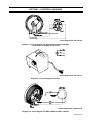
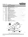
February 1992
FORM: OM-823G
Effective With Serial No. KB055102
MODEL: RHC-3
RHC-3-2
RHC-3GD9A
RHC-3GD25B
RHCS-3
RHC-3-GD34A
RHC-14
RHC-23
OWNER’S MANUAL
IMPORTANT: Read and understand the entire contents of both this manual
and the power source manual used with this unit, with special emphasis on
the safety material throughout both manuals, before installing, operating, or
maintaining this equipment. This unit and these instructions are for use only
by persons trained and experienced in the safe operation of welding equipment. Do not allow untrained persons to install, operate, or maintain this unit.
Contact your distributor if you do not fully understand these instructions.
SA-141 127
MILLER ELECTRIC Mfg. Co.
A Miller Group Ltd., Company
P.O. Box 1079
Appleton, WI 54912 USA
Tel. 414-734-9821
PRINTED IN U.S.A.
OM-823G - 2/92
RECEIVING-HANDLING
Before unpacking equipment, check carton for any
damage that may have occurred during shipment. File
any claims for loss or damage with the delivering carrier. Assistance for filing or settling claims may be obtained from the distributor and/or the equipment manufacturer’s Transportation Department.
When requesting information about this equipment, always provide the Model Description and Serial or Style
Number.
Use the following spaces to record the Model Designation and Serial or Style Number of your unit. The information is located on the rating label or nameplate.
Model
Serial or Style No.
Date of Purchase
TABLE OF CONTENTS
Section No.
Page No.
SECTION 1 − SAFETY PRECAUTIONS AND SIGNAL WORDS
1-1.
1-2.
1-3.
General Information And Safety . . . . . . . . . . . . . . . . . . . . . . . . . . . . . . .
Safety Alert Symbol And Signal Words . . . . . . . . . . . . . . . . . . . . . . . . .
Description . . . . . . . . . . . . . . . . . . . . . . . . . . . . . . . . . . . . . . . . . . . . . . . . .
1
1
1
SECTION 2 − INSTALLATION
2-1.
2-2.
Location . . . . . . . . . . . . . . . . . . . . . . . . . . . . . . . . . . . . . . . . . . . . . . . . . . . .
Interconnections . . . . . . . . . . . . . . . . . . . . . . . . . . . . . . . . . . . . . . . . . . . . .
1
1
SECTION 3 − OPERATOR CONTROLS
3-1.
3-2.
Operation . . . . . . . . . . . . . . . . . . . . . . . . . . . . . . . . . . . . . . . . . . . . . . . . . . .
Contactor Switch . . . . . . . . . . . . . . . . . . . . . . . . . . . . . . . . . . . . . . . . . . . .
2
2
SECTION 4 − MAINTENANCE
SECTION 5 − ELECTRICAL DIAGRAMS
Diagram 5-1.
Diagram 5-2.
Diagram 5-3.
Diagram 5-4.
Diagram 5-5.
Circuit Diagram For Remote Hand Control Used With
Transformer Arc Welding Power Source . . . . . . . . . . . . . . . .
Circuit Diagram For RHCS-3 . . . . . . . . . . . . . . . . . . . . . . . . . .
Circuit Diagram For RHC-3-GD9A And RHC-3-GD34A . . . .
Circuit Diagram For RHC-3-GD25B . . . . . . . . . . . . . . . . . . . .
Circuit Diagram For RHC-14 And RHC-23 . . . . . . . . . . . . . . .
3
3
3
4
4
SECTION 6 − PARTS LIST
Figure 6-1. Complete Assembly (RHC-3 Illustrated) . . . . . . . . . . . . . . . . . . . . .
6
LIST OF CHARTS AND TABLES
Table 2-1. Cord Conductor Length And Size . . . . . . . . . . . . . . . . . . . . . . . . . . .
1
SECTION 1 − SAFETY PRECAUTIONS AND SIGNAL WORDS
1-1.
GENERAL INFORMATION AND SAFETY
A. General
identify different levels of hazard and special instructions.
This safety alert symbol is used with the signal
words WARNING and CAUTION to call attention to the safety statements.
Information presented in this manual and on various labels, tags, and plates on the unit pertains to equipment
design, installation, operation, maintenance, and
troubleshooting which should be read, understood, and
followed for the safe and effective use of this equipment.
WARNING statements identify procedures or
practices which must be followed to avoid serious personal injury or loss of life.
The nameplate of this unit uses international symbols
for labeling the front panel controls. The symbols also
appear at the appropriate section in the text.
CAUTION statements identify procedures or
practices which must be followed to avoid minor
personal injury or damage to this equipment.
B. Safety
The installation, operation, maintenance, and troubleshooting of arc welding equipment requires practices
and procedures which ensure personal safety and the
safety of others. Therefore, this equipment is to be installed, operated, and maintained only by qualified persons in accordance with this manual and all applicable
codes such as, but not limited to, those listed at the end
of Section 1 − Safety Rules For Operation Of Arc Welding Power Source.
1-2.
SAFETY ALERT SYMBOL AND SIGNAL
WORDS
The following safety alert symbol and signal words are
used throughout this manual to call attention to and
IMPORTANT statements identify special instructions
necessary for the most efficient operation of this equipment.
1-3.
DESCRIPTION
Remote Hand Controls are designed for use as remote
amperage or voltage controls in conjunction with a welding power source or welding generator having electric
control facilities. Remote Hand Controls with the letters
GD displayed in the model description are designed for
use with welding generators only.
SECTION 2 − INSTALLATION
Table 2-1. Cord Conductor Length And Size
Amperage or Voltage Control
Cord Length
Conductor
Size*
Up to 20ft (6 m)
Up to 20ft (6 m) (GD Models)
21 to 100ft (6 to 30 m) (GD Models)
21 to 50ft (6 to 15 m)
51 to 100ft (16 to 31 m)
101 to 200ft (31 to 61 m)
No. 16
No. 14
No. 12
No. 14
No. 12
No. 10
source or welding generator. The Remote Hand Control
can be wall mounted or placed on a stand at the work
area.
If it is necessary to install a muti-conductor cord of longer length, refer to Table 2-1 for cord conductor size according to the desired length. Refer to Section 5 - Electrical Diagrams for connections
2-2.
1.
To make connections on models equipped with
the twistlock plug, fully insert the twistlock plug
that is attached to the Remote Hand Control cord
into Remote Amperage or Voltage Control Receptacle on the welding power source or welding
generator. Turn the cap in a clockwise direction,
as far as it will turn, to lock the connection.
2.
To make connections on models equipped with
the 14-pin or 5-pin Amphenol plug, align keyway,
insert plug, and rotate threaded collar fully clockwise.
*AWG-American Wire Guage
2-1.
LOCATION
The Remote Hand Controls is equipped with a twenty
foot (6 m) interconnecting multi-conductor cord (unless
otherwise specified) which enables the Remote Hand
Control to be remotely located from the welding power
INTERCONNECTIONS
OM-823 Page 1
SECTION 3 − OPERATOR CONTROLS
3-1.
OPERATION
B. Remote Hand Control Of Two Welding Power
Sources
A. General
When a Remote Hand Control is being used, it should
be noted that on most welding power sources or welding
generators, the Remote Hand Control functions as a
fine amperage or voltage adjustment of the Amperage
or Voltage Adjustment Control setting on the welding
power source or welding generator. For example, if the
Amperage or Voltage Adjustment Control on the welding power source or welding generator is set at the midpoint position, the Remote Hand Control will provide
(from its minimum to maximum positions) fine adjustment of one half of the welding power source or welding
generator output. If full adjustment of the maximum output of the welding power source or welding generator
from the Remote Hand Control is desired, it will be necessary to rotate the Amperage or Voltage Adjustment
Control on the welding generator to the maximum position. The Remote Hand Control dial is calibrated in percentage in increments of ten from 0 to 100 percent.
On some welding power source or welding generators
the Amperage Voltage Adjustment Control on the Welding power source or welding generator is inoperative
when a Remote Hand Control is connected in the welding power source or welding generator control circuitry.
In this situation, the Remote Hand Control provides
complete control from the minimum to the maximum
output of the welding power source or welding generator
rather than fine adjustment of the Amperage or Voltage
Adjustment control setting on the welding power source
or welding generator.
To determine in which way the Remote Hand Control affects the operation of the welding power source or welding generator, refer to the welding power source or welding generator circuit diagram and/or instruction Manual.
Remote amperage or voltage control of two welding
power sources from one Remote Hand Control is made
possible through the use of Remote Hand Control having two rheostats. These Remote Hand Controls are
identified by a model suffix of -2, and are designed to simultaneously control two identical welding power
sources. These Remote Hand Controls have two rheostats coupled on a common control shaft. Rotating the
knob on the Remote Hand Control simultaneously adjusts each rheostat in the control to the same value,
thus making possible remote control of two welding
power sources from a single Remote Hand Control.
IMPORTANT: When a Remote Hand Control is used,
refer to the Instruction Manual of the welding power
source or welding generator for additional operational
information.
3-2.
CONTACTOR SWITCH
WARNING: ELECTRIC SHOCK can kill.
• Do not touch live electrical parts
•
•
Do not touch the weld output terminals when
the contactor is energized.
Do not touch electrode and work clamp at the
same time.
IMPORTANT: To use the RHC-14 or RHC-23 contactor
switch, the OUTPUT (CONTACTOR) switch on the
welding power source must be in the Remote position
for proper remote control operation.
The RHC-14 or RHC-23 switch has two positions, ON
and OFF. Placing this switch in the ON position provides
open-circuit voltage. Placing this switch in the OFF position stops open-circuit voltage (ocv goes to zero).
SECTION 4 − MAINTENANCE
WARNING: ELECTRIC SHOCK can kill; HOT
SURFACES can cause severe burns.
• Do not touch live electrical parts.
and at the strain relief connector on the Remote Hand
Control base. Repair all breaks with electrical tape, or
replace the cord if necessary.
Disconnect plugs from power source before
inspecting or servicing.
Allow unit to cool before servicing.
Daily, rotate the Remote Hand Control knob from the 0
to 100 percent position. This procedure will prevent oxidation from forming on the contacts, which could insulate the contacts from the brush, causing the control to
become inoperative. Refer to Table 2-1 for proper cord
conductor size and to Diagrams 5-1 through 5-5 for
proper cord conductor connections.
•
•
Once a month inspect the Remote Hand Control cord for
breaks in the insulating jacket particularly at the plug
OM-823 Page 2
SECTION 5 − ELECTRICAL DIAGRAMS
Circuit Diagram No. SA-150 670
Diagram 5-1. Circuit Diagram For Remote Hand Control Used With
Transformer Arc Welding Power Source
Circuit Diagram No. SA-150 671
Diagram 5-2. Circuit Diagram For RHCS-3
Circuit Diagram No. SA-094 231-A
Diagram 5-3. Circuit Diagram For RHC-3-GD9A And RHC-3-GD34A
OM-823 Page 3
Circuit Diagram No. SA-094 232-A
Diagram 5-4. Circuit Diagram For RHC-3-GD25B
Circuit Diagram No. SA-053 656-A
Diagram 5-5. Circuit Diagram For RHC-14 And RHC-23
OM-823 Page 4
SECTION 6 − PARTS LIST
OM-823 Page 5
Quantity
Model
Item Dia.
No. Mkgs.
Part
No.
RHC- RHC3
3-2
Description
RHC14
RHC- RHCS23
3
Figure 6-1. Complete Assembly
. . 1 . R1 . . 030 653
. . 1 . R1 . . 107 363
. . 1 . R1 . . 035 897
. . 1 . R1 . . 039 272
. . 2 . . . . . . +021 475
. . 2 . . . . . . +014 417
. . . . . . . . . . . 085 220
. . 3 . . . . . . . 021 474
. . 3 . . . . . . . 106 952
. . 3 . . . . . . . 109 974
. . 4 PLG1 605 797
. . 4 PLG1 144 310
. . . . . . . . . . . 134 732
. . . . . . . . . . . 143 922
. . 4 PLG1 039 273
. . . . . . . . . . . 039 685
. . 5 . . . . . . . 600 733
. . 5 . . . . . . . 052 246
. . 6 . . . . . . . 010 659
. . 6 . . . . . . . 070 654
. . 7 . . . . . . . 097 926
. . 7 . . . . . . . 097 922
. . 8 . . . . . . . 039 411
. . 8 . . . . . . . 148 720
. . 8 . . . . . . . 130 214
. . 8 . . . . . . . 053 574
. . 8 . . . . . . . 148 716
. . . . . S1 . . 011 609
. . . . . . . . . . . 604 311
. . RHEOSTAT, WW 150W 15 ohm . . . . . . . . . . . . . . . . . . . . . . 1
. . RHEOSTAT, WW 150W 15 ohm . . . . . . . . . . . . . . . . . . . . . . . . . . . . 1
. . POTENTIOMETER, C sltd sft 1/T 2W 1000 ohm . . . . . . . . . . . . . . . . . . . 1 . . . 1
. . RHEOSTAT, WW 150W 1250 ohm . . . . . . . . . . . . . . . . . . . . . . . . . . . . . . . . . . . . . . . . . .
. . WRAPPER . . . . . . . . . . . . . . . . . . . . . . . . . . . . . . . . . . . . . . . . 1 . . . 1 . . . . . . . . . . . . . .
. . WRAPPER . . . . . . . . . . . . . . . . . . . . . . . . . . . . . . . . . . . . . . . . . . . . . . . . . . . 1 . . . 1
. . LABEL, caution electric circuit . . . . . . . . . . . . . . . . . . . . . . . . 1 . . . 1 . . . 1 . . . 1 . .
. . CASE SECTION, base/front/rear . . . . . . . . . . . . . . . . . . . . . . 1 . . . . . . . . . . . . . . . . . . .
. . CASE SECTION, base/front/rear . . . . . . . . . . . . . . . . . . . . . . . . . . . . 1
. . CASE SECTION, base/front/rear . . . . . . . . . . . . . . . . . . . . . . . . . . . . . . . . . 1 . . . 1
. . PLUG, twlk 3P3W 20A 125V . . . . . . . . . . . . . . . . . . . . . . . . . 1 . . . 2
. . HOUSING PLUG & PINS, (consisting of) . . . . . . . . . . . . . . . . . . . . . . . . . . 1
. . . . TERMINAL, male 1 pin 24-20 wire . . . . . . . . . . . . . . . . . . . . . . . . . . . . . . 14
. . CLAMP, cable strain relief sz 17 & 20 . . . . . . . . . . . . . . . . . . . . . . . . . . . . . 1
. . PLUG, 5 pin MS-3106A-16S-8P . . . . . . . . . . . . . . . . . . . . . . . . . . . . . . . . . . . . . . . 1 . .
. . CLAMP, cable AN-3057-8 . . . . . . . . . . . . . . . . . . . . . . . . . . . . . . . . . . . . . . . . . . . . . 1 . .
. . CORD SET, pwr 115V 16ga 3/c 20ft . . . . . . . . . . . . . . . . . . . 1 . . . 2 . . . . . . . . . . . . . .
. . CABLE, pwr 20ga 5/c (order by ft) . . . . . . . . . . . . . . . . . . . . . . . . . . . . . . . 20ft . 20ft
. . CONNECTOR, clamp cable .375 90deg . . . . . . . . . . . . . . . . 1 . . . 2 . . . . . . . . . . . . . .
. . BUSHING, strain relief .300 ID x .550mtg hole . . . . . . . . . . . . . . . . . . . . . 1 . . . 1
. . KNOB, pointer 2.375dia x .250 ID . . . . . . . . . . . . . . . . . . . . . 1 . . . 1 . . . . . . . . . . . . . .
. . KNOB, pointer .875dia x .250 ID . . . . . . . . . . . . . . . . . . . . . . . . . . . . . . . . . 1 . . . 1
. . NAMEPLATE . . . . . . . . . . . . . . . . . . . . . . . . . . . . . . . . . . . . . . . 1
. . NAMEPLATE . . . . . . . . . . . . . . . . . . . . . . . . . . . . . . . . . . . . . . . . . . . . . 1
. . NAMEPLATE . . . . . . . . . . . . . . . . . . . . . . . . . . . . . . . . . . . . . . . . . . . . . . . . . . 1
. . PLATE, ind current . . . . . . . . . . . . . . . . . . . . . . . . . . . . . . . . . . . . . . . . . . . . . . . . . . . 1
. . NAMEPLATE . . . . . . . . . . . . . . . . . . . . . . . . . . . . . . . . . . . . . . . . . . . . . . . . . . . . . . . . . . . . .
. . SWITCH, tgl SPDT 15A 125VAC . . . . . . . . . . . . . . . . . . . . . . . . . . . . . . . . . 1 . . . 1
. . GROMMET, rbr .250 ID x .375mtg hole . . . . . . . . . . . . . . . . . . . . . . . . . . . . . . . . . 1
1
1
1
1
1
1
1
1
1
1
1
2
8
3
7
4
6
5
SA-141 128
Figure 6-1. Complete Assembly (RHC-3 Illustrated)
+When ordering a component originally displaying a precautionary label, the label should also be ordered.
BE SURE TO PROVIDE MODEL AND SERIAL NUMBER WHEN ORDERING REPLACEMENT PARTS.
OM-823 Page 6
Item Dia.
No. Mkgs.
Quantity
Model
RHC-3-GD
Part
No.
Description
9A
25B
34A
Complete Assembly (Use Fig 6-1 View)
. . 1 . . . R1 . 005 355
. . 1 . . . R1 . 605 049
. . 1 . . . R1 . 605 960
. . 2 . . . R1 +021 475
. . . . . . . . . . . . 085 220
. . 3 . . . . . . . . 021 474
. . 4 . PLG1 032 898
. . 4 . PLG1 039 621
. . 5 . . . . . . . . 600 349
. . 5 . . . . . . . . 604 834
. . 6 . . . . . . . . 010 659
. . 7 . . . . . . . . 097 926
. . 7 . . . . . . . . 148 723
. . 8 . . . . . . . . 006 101
. . 8 . . . . . . . . 013 615
. . 8 . . . . . . . . 148 717
..
..
..
..
..
..
..
..
..
..
..
..
..
..
..
..
RHEOSTAT, WW 50W 9 ohm . . . . . . . . . . . . . . . . . . . . . . . . . . . . . . . 1
RHEOSTAT, WW 300W 25 ohm . . . . . . . . . . . . . . . . . . . . . . . . . . . . . . . . . . 1
RHEOSTAT, WW 300W 34 ohm . . . . . . . . . . . . . . . . . . . . . . . . . . . . . . . . . . . . . . . . . . 1
WRAPPER . . . . . . . . . . . . . . . . . . . . . . . . . . . . . . . . . . . . . . . . . . . . . . . 1 . . . 1 . . . . . 1
LABEL, caution electrical circuit . . . . . . . . . . . . . . . . . . . . . . . . . . . . . 1 . . . 1 . . . . . 1
CASE SECTION, base/front/rear . . . . . . . . . . . . . . . . . . . . . . . . . . . . 1 . . . 1 . . . . . . 1
PLUG, twlk grd 2P3W 15A 125V . . . . . . . . . . . . . . . . . . . . . . . . . . . . 1 . . . . . . . . . . . 1
PLUG, twlk armd 4P4W 20A 250V . . . . . . . . . . . . . . . . . . . . . . . . . . . . . . . . 1
CABLE, port No.14 3/c (order by ft) . . . . . . . . . . . . . . . . . . . . . . . . . 20ft . . . . . . . 20ft
CABLE, port No.14 4/c (order by ft) . . . . . . . . . . . . . . . . . . . . . . . . . . . . . . 20ft
CONNECTOR, clamp .375 90deg . . . . . . . . . . . . . . . . . . . . . . . . . . . 1 . . . 1 . . . . . 1
KNOB, pointer 2.375dia x .250 ID . . . . . . . . . . . . . . . . . . . . . . . . . . . . 1
KNOB, pointer 2.375dia x .379 ID . . . . . . . . . . . . . . . . . . . . . . . . . . . . . . . . . 1 . . . . . 1
PLATE, ind amperage . . . . . . . . . . . . . . . . . . . . . . . . . . . . . . . . . . . . . . 1
PLATE, ind amperage . . . . . . . . . . . . . . . . . . . . . . . . . . . . . . . . . . . . . . . . . . . 1
NAMEPLATE . . . . . . . . . . . . . . . . . . . . . . . . . . . . . . . . . . . . . . . . . . . . . . . . . . . . . . . . . . 1
+When ordering a component originally displaying a precautionary label, the label should also be ordered.
BE SURE TO PROVIDE MODEL AND SERIAL NUMBER WHEN ORDERING REPLACEMENT PARTS.
OM-823 Page 7