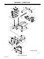
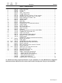
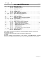
1
OM-1096 091 504D February 2001 Processes Automatic Welding Description Automatic Welding Motorized Slide MOTORIZED SLIDE MSC-2 Visit our website at www.MillerWelds.com From Miller to You Thank you and congratulations on choosing Miller. Now you can get the job done and get it done right. We know you don’t have time to do it any other way. That’s why when Niels Miller first started building arc welders in 1929, he made sure his products offered long-lasting value and superior quality. Like you, his customers couldn’t afford anything less. Miller products had to be more than the best they could be. They had to be the best you could buy. Today, the people that build and sell Miller products continue the tradition. They’re just as committed to providing equipment and service that meets the high standards of quality and value established in 1929. This Owner’s Manual is designed to help you get the most out of your Miller products. Please take time to read the Safety precautions. They will help you protect yourself against potential hazards on the worksite. We’ve made installation and operation quick and easy. With Miller you can count on years of reliable service with proper maintenance. And if for some reason the unit needs repair, there’s a Troubleshooting section that will Miller is the first welding help you figure out what the problem is. The equipment manufacturer in parts list will then help you to decide which the U.S.A. to be registered to the ISO 9001 Quality System exact part you may need to fix the problem. Standard. Warranty and service information for your particular model are also provided. Working as hard as you do – every power source from Miller is backed by the most hassle-free warranty in the business. Miller offers a Technical Manual which provides more detailed service and parts information for your unit. To obtain a Technical Manual, contact your local distributor. Your distributor can also supply you with Welding Process Manuals such as SMAW, GTAW, GMAW, and GMAW-P. Miller Electric manufactures a full line of welders and welding related equipment. For information on other quality Miller products, contact your local Miller distributor to receive the latest full line catalog or individual catalog sheets. To locate your nearest distributor or service agency call 1-800-4-A-Miller, or visit us at www.MillerWelds.com on the web. TABLE OF CONTENTS SECTION 1 – SAFETY PRECAUTIONS - READ BEFORE USING . . . . . . . . . . . . . . . . . . . . . . . . . . . 1-1. Symbol Usage . . . . . . . . . . . . . . . . . . . . . . . . . . . . . . . . . . . . . . . . . . . . . . . . . . . . . . . . . . . . . . . . 1-2. Arc Welding Hazards . . . . . . . . . . . . . . . . . . . . . . . . . . . . . . . . . . . . . . . . . . . . . . . . . . . . . . . . . . 1-3. Additional Symbols For Installation, Operation, And Maintenance . . . . . . . . . . . . . . . . . . . . . 1-4. Principal Safety Standards . . . . . . . . . . . . . . . . . . . . . . . . . . . . . . . . . . . . . . . . . . . . . . . . . . . . . 1-5. EMF Information . . . . . . . . . . . . . . . . . . . . . . . . . . . . . . . . . . . . . . . . . . . . . . . . . . . . . . . . . . . . . . SECTION 2 – SPECIFICATIONS . . . . . . . . . . . . . . . . . . . . . . . . . . . . . . . . . . . . . . . . . . . . . . . . . . . . . . . . 2-1. Motorized Slide Specifications . . . . . . . . . . . . . . . . . . . . . . . . . . . . . . . . . . . . . . . . . . . . . . . . . . . 2-2. MSC-2 Specifications . . . . . . . . . . . . . . . . . . . . . . . . . . . . . . . . . . . . . . . . . . . . . . . . . . . . . . . . . . 2-3. Load Data . . . . . . . . . . . . . . . . . . . . . . . . . . . . . . . . . . . . . . . . . . . . . . . . . . . . . . . . . . . . . . . . . . . 2-4. Motorized Slide Dimensions . . . . . . . . . . . . . . . . . . . . . . . . . . . . . . . . . . . . . . . . . . . . . . . . . . . . 2-5. MSC-2 Dimensions . . . . . . . . . . . . . . . . . . . . . . . . . . . . . . . . . . . . . . . . . . . . . . . . . . . . . . . . . . . . SECTION 3 – INSTALLATION . . . . . . . . . . . . . . . . . . . . . . . . . . . . . . . . . . . . . . . . . . . . . . . . . . . . . . . . . . 3-1. Location . . . . . . . . . . . . . . . . . . . . . . . . . . . . . . . . . . . . . . . . . . . . . . . . . . . . . . . . . . . . . . . . . . . . . 3-2. Interconnecting And Power Cord Installation . . . . . . . . . . . . . . . . . . . . . . . . . . . . . . . . . . . . . . . 3-3. Remote Movement Control Connections . . . . . . . . . . . . . . . . . . . . . . . . . . . . . . . . . . . . . . . . . . 3-4. Installing Gun Onto Mounting Plate . . . . . . . . . . . . . . . . . . . . . . . . . . . . . . . . . . . . . . . . . . . . . . SECTION 4 – OPERATION . . . . . . . . . . . . . . . . . . . . . . . . . . . . . . . . . . . . . . . . . . . . . . . . . . . . . . . . . . . . 4-1. MSC-2 Control . . . . . . . . . . . . . . . . . . . . . . . . . . . . . . . . . . . . . . . . . . . . . . . . . . . . . . . . . . . . . . . 4-2. Motorized Slide Limit Switch . . . . . . . . . . . . . . . . . . . . . . . . . . . . . . . . . . . . . . . . . . . . . . . . . . . . SECTION 5 – MAINTENANCE & TROUBLESHOOTING . . . . . . . . . . . . . . . . . . . . . . . . . . . . . . . . . . . 5-2. Overload Protection . . . . . . . . . . . . . . . . . . . . . . . . . . . . . . . . . . . . . . . . . . . . . . . . . . . . . . . . . . . 5-3. Slide Maintenance . . . . . . . . . . . . . . . . . . . . . . . . . . . . . . . . . . . . . . . . . . . . . . . . . . . . . . . . . . . . 5-1. Routine Maintenance . . . . . . . . . . . . . . . . . . . . . . . . . . . . . . . . . . . . . . . . . . . . . . . . . . . . . . . . . . 5-4. Drive Belt Adjustment . . . . . . . . . . . . . . . . . . . . . . . . . . . . . . . . . . . . . . . . . . . . . . . . . . . . . . . . . . 5-5. Troubleshooting . . . . . . . . . . . . . . . . . . . . . . . . . . . . . . . . . . . . . . . . . . . . . . . . . . . . . . . . . . . . . . SECTION 6 – ELECTRICAL DIAGRAMS . . . . . . . . . . . . . . . . . . . . . . . . . . . . . . . . . . . . . . . . . . . . . . . . SECTION 7 – PARTS LIST . . . . . . . . . . . . . . . . . . . . . . . . . . . . . . . . . . . . . . . . . . . . . . . . . . . . . . . . . . . . . WARRANTY OM-1096 1 1 1 3 3 4 5 5 5 5 6 6 7 7 7 8 8 9 9 10 10 10 11 10 11 12 13 14 SECTION 1 – SAFETY PRECAUTIONS - READ BEFORE USING som _nd_4/98 1-1. Symbol Usage Means Warning! Watch Out! There are possible hazards with this procedure! The possible hazards are shown in the adjoining symbols. Y Marks a special safety message. . Means “Note”; not safety related. This group of symbols means Warning! Watch Out! possible ELECTRIC SHOCK, MOVING PARTS, and HOT PARTS hazards. Consult symbols and related instructions below for necessary actions to avoid the hazards. 1-2. Arc Welding Hazards Y The symbols shown below are used throughout this manual to call attention to and identify possible hazards. When you see the symbol, watch out, and follow the related instructions to avoid the hazard. The safety information given below is only a summary of the more complete safety information found in the Safety Standards listed in Section 1-4. Read and follow all Safety Standards. D If earth grounding of the workpiece is required, ground it directly with a separate cable. Y Only qualified persons should install, operate, maintain, and repair this unit. D Wear a safety harness if working above floor level. D Keep all panels and covers securely in place. Y During operation, keep everybody, especially children, away. D Clamp work cable with good metal-to-metal contact to workpiece or worktable as near the weld as practical. ELECTRIC SHOCK can kill. Touching live electrical parts can cause fatal shocks or severe burns. The electrode and work circuit is electrically live whenever the output is on. The input power circuit and machine internal circuits are also live when power is on. In semiautomatic or automatic wire welding, the wire, wire reel, drive roll housing, and all metal parts touching the welding wire are electrically live. Incorrectly installed or improperly grounded equipment is a hazard. D Do not touch electrode if you are in contact with the work, ground, or another electrode from a different machine. D Use only well-maintained equipment. Repair or replace damaged parts at once. Maintain unit according to manual. D Insulate work clamp when not connected to workpiece to prevent contact with any metal object. D Do not connect more than one electrode or work cable to any single weld output terminal. SIGNIFICANT DC VOLTAGE exists after removal of input power on inverters. D Turn Off inverter, disconnect input power, and discharge input capacitors according to instructions in Maintenance Section before touching any parts. D Do not touch live electrical parts. D Wear dry, hole-free insulating gloves and body protection. D Insulate yourself from work and ground using dry insulating mats or covers big enough to prevent any physical contact with the work or ground. D Do not use AC output in damp areas, if movement is confined, or if there is a danger of falling. D Use AC output ONLY if required for the welding process. D If AC output is required, use remote output control if present on unit. D Disconnect input power or stop engine before installing or servicing this equipment. Lockout/tagout input power according to OSHA 29 CFR 1910.147 (see Safety Standards). D Properly install and ground this equipment according to its Owner’s Manual and national, state, and local codes. D Keep your head out of the fumes. Do not breathe the fumes. D Always verify the supply ground – check and be sure that input power cord ground wire is properly connected to ground terminal in disconnect box or that cord plug is connected to a properly grounded receptacle outlet. D When making input connections, attach proper grounding conductor first – double-check connections. D Frequently inspect input power cord for damage or bare wiring – replace cord immediately if damaged – bare wiring can kill. D Turn off all equipment when not in use. D Do not use worn, damaged, undersized, or poorly spliced cables. D Do not weld in locations near degreasing, cleaning, or spraying operations. The heat and rays of the arc can react with vapors to form highly toxic and irritating gases. D Do not drape cables over your body. FUMES AND GASES can be hazardous. Welding produces fumes and gases. Breathing these fumes and gases can be hazardous to your health. D If inside, ventilate the area and/or use exhaust at the arc to remove welding fumes and gases. D If ventilation is poor, use an approved air-supplied respirator. D Read the Material Safety Data Sheets (MSDSs) and the manufacturer’s instructions for metals, consumables, coatings, cleaners, and degreasers. D Work in a confined space only if it is well ventilated, or while wearing an air-supplied respirator. Always have a trained watchperson nearby. Welding fumes and gases can displace air and lower the oxygen level causing injury or death. Be sure the breathing air is safe. D Do not weld on coated metals, such as galvanized, lead, or cadmium plated steel, unless the coating is removed from the weld area, the area is well ventilated, and if necessary, while wearing an air-supplied respirator. The coatings and any metals containing these elements can give off toxic fumes if welded. OM-1096 Page 1 ARC RAYS can burn eyes and skin. Arc rays from the welding process produce intense visible and invisible (ultraviolet and infrared) rays that can burn eyes and skin. Sparks fly off from the weld. D Wear a welding helmet fitted with a proper shade of filter to protect your face and eyes when welding or watching (see ANSI Z49.1 and Z87.1 listed in Safety Standards). D Wear approved safety glasses with side shields under your helmet. D Use protective screens or barriers to protect others from flash and glare; warn others not to watch the arc. D Wear protective clothing made from durable, flame-resistant material (leather and wool) and foot protection. BUILDUP OF GAS can injure or kill. D Shut off shielding gas supply when not in use. D Always ventilate confined spaces or use approved air-supplied respirator. HOT PARTS can cause severe burns. D Do not touch hot parts bare handed. D Allow cooling period before working on gun or torch. MAGNETIC FIELDS can affect pacemakers. WELDING can cause fire or explosion. Welding on closed containers, such as tanks, drums, or pipes, can cause them to blow up. Sparks can fly off from the welding arc. The flying sparks, hot workpiece, and hot equipment can cause fires and burns. Accidental contact of electrode to metal objects can cause sparks, explosion, overheating, or fire. Check and be sure the area is safe before doing any welding. D Protect yourself and others from flying sparks and hot metal. D Do not weld where flying sparks can strike flammable material. D Remove all flammables within 35 ft (10.7 m) of the welding arc. If this is not possible, tightly cover them with approved covers. D Be alert that welding sparks and hot materials from welding can easily go through small cracks and openings to adjacent areas. D Watch for fire, and keep a fire extinguisher nearby. D Be aware that welding on a ceiling, floor, bulkhead, or partition can cause fire on the hidden side. D Do not weld on closed containers such as tanks, drums, or pipes, unless they are properly prepared according to AWS F4.1 (see Safety Standards). D Connect work cable to the work as close to the welding area as practical to prevent welding current from traveling long, possibly unknown paths and causing electric shock and fire hazards. D Do not use welder to thaw frozen pipes. D Remove stick electrode from holder or cut off welding wire at contact tip when not in use. D Wear oil-free protective garments such as leather gloves, heavy shirt, cuffless trousers, high shoes, and a cap. D Remove any combustibles, such as a butane lighter or matches, from your person before doing any welding. FLYING METAL can injure eyes. D Welding, chipping, wire brushing, and grinding cause sparks and flying metal. As welds cool, they can throw off slag. D Wear approved safety glasses with side shields even under your welding helmet. OM-1096 Page 2 D Pacemaker wearers keep away. D Wearers should consult their doctor before going near arc welding, gouging, or spot welding operations. NOISE can damage hearing. Noise from some processes or equipment can damage hearing. D Wear approved ear protection if noise level is high. CYLINDERS can explode if damaged. Shielding gas cylinders contain gas under high pressure. If damaged, a cylinder can explode. Since gas cylinders are normally part of the welding process, be sure to treat them carefully. D Protect compressed gas cylinders from excessive heat, mechanical shocks, slag, open flames, sparks, and arcs. D Install cylinders in an upright position by securing to a stationary support or cylinder rack to prevent falling or tipping. D Keep cylinders away from any welding or other electrical circuits. D Never drape a welding torch over a gas cylinder. D Never allow a welding electrode to touch any cylinder. D Never weld on a pressurized cylinder – explosion will result. D Use only correct shielding gas cylinders, regulators, hoses, and fittings designed for the specific application; maintain them and associated parts in good condition. D Turn face away from valve outlet when opening cylinder valve. D Keep protective cap in place over valve except when cylinder is in use or connected for use. D Read and follow instructions on compressed gas cylinders, associated equipment, and CGA publication P-1 listed in Safety Standards. 1-3. Additional Symbols For Installation, Operation, And Maintenance FIRE OR EXPLOSION hazard. MOVING PARTS can cause injury. D Do not install or place unit on, over, or near combustible surfaces. D Do not install unit near flammables. D Do not overload building wiring – be sure power supply system is properly sized, rated, and protected to handle this unit. D Keep away from moving parts such as fans. D Keep all doors, panels, covers, and guards closed and securely in place. FALLING UNIT can cause injury. H.F. RADIATION can cause interference. D Use lifting eye to lift unit only, NOT running gear, gas cylinders, or any other accessories. D Use equipment of adequate capacity to lift and support unit. D If using lift forks to move unit, be sure forks are long enough to extend beyond opposite side of unit. D OVERUSE can cause OVERHEATING D D Allow cooling period; follow rated duty cycle. D Reduce current or reduce duty cycle before starting to weld again. D Do not block or filter airflow to unit. D D D High-frequency (H.F.) can interfere with radio navigation, safety services, computers, and communications equipment. D Have only qualified persons familiar with electronic equipment perform this installation. The user is responsible for having a qualified electrician promptly correct any interference problem resulting from the installation. If notified by the FCC about interference, stop using the equipment at once. Have the installation regularly checked and maintained. Keep high-frequency source doors and panels tightly shut, keep spark gaps at correct setting, and use grounding and shielding to minimize the possibility of interference. STATIC (ESD) can damage PC boards. D Put on grounded wrist strap BEFORE handling boards or parts. D Use proper static-proof bags and boxes to store, move, or ship PC boards. ARC WELDING can cause interference. MOVING PARTS can cause injury. D Keep away from moving parts. D Keep away from pinch points such as drive rolls. D D WELDING WIRE can cause injury. D Do not press gun trigger until instructed to do so. D Do not point gun toward any part of the body, other people, or any metal when threading welding wire. D D D Electromagnetic energy can interfere with sensitive electronic equipment such as computers and computer-driven equipment such as robots. D Be sure all equipment in the welding area is electromagnetically compatible. To reduce possible interference, keep weld cables as short as possible, close together, and down low, such as on the floor. Locate welding operation 100 meters from any sensitive electronic equipment. Be sure this welding machine is installed and grounded according to this manual. If interference still occurs, the user must take extra measures such as moving the welding machine, using shielded cables, using line filters, or shielding the work area. 1-4. Principal Safety Standards Safety in Welding and Cutting, ANSI Standard Z49.1, from American Welding Society, 550 N.W. LeJeune Rd, Miami FL 33126 Safety and Health Standards, OSHA 29 CFR 1910, from Superintendent of Documents, U.S. Government Printing Office, Washington, D.C. 20402. Recommended Safe Practices for the Preparation for Welding and Cutting of Containers That Have Held Hazardous Substances, American Welding Society Standard AWS F4.1, from American Welding Society, 550 N.W. LeJeune Rd, Miami, FL 33126 National Electrical Code, NFPA Standard 70, from National Fire Protection Association, Batterymarch Park, Quincy, MA 02269. Safe Handling of Compressed Gases in Cylinders, CGA Pamphlet P-1, from Compressed Gas Association, 1235 Jefferson Davis Highway, Suite 501, Arlington, VA 22202. Code for Safety in Welding and Cutting, CSA Standard W117.2, from Canadian Standards Association, Standards Sales, 178 Rexdale Boulevard, Rexdale, Ontario, Canada M9W 1R3. Safe Practices For Occupation And Educational Eye And Face Protection, ANSI Standard Z87.1, from American National Standards Institute, 1430 Broadway, New York, NY 10018. Cutting And Welding Processes, NFPA Standard 51B, from National Fire Protection Association, Batterymarch Park, Quincy, MA 02269. OM-1096 Page 3 1-5. EMF Information Considerations About Welding And The Effects Of Low Frequency Electric And Magnetic Fields Welding current, as it flows through welding cables, will cause electromagnetic fields. There has been and still is some concern about such fields. However, after examining more than 500 studies spanning 17 years of research, a special blue ribbon committee of the National Research Council concluded that: “The body of evidence, in the committee’s judgment, has not demonstrated that exposure to powerfrequency electric and magnetic fields is a human-health hazard.” However, studies are still going forth and evidence continues to be examined. Until the final conclusions of the research are reached, you may wish to minimize your exposure to electromagnetic fields when welding or cutting. To reduce magnetic fields in the workplace, use the following procedures: OM-1096 Page 4 1. Keep cables close together by twisting or taping them. 2. Arrange cables to one side and away from the operator. 3. Do not coil or drape cables around your body. 4. Keep welding power source and cables as far away from operator as practical. 5. Connect work clamp to workpiece as close to the weld as possible. About Pacemakers: Pacemaker wearers consult your doctor first. If cleared by your doctor, then following the above procedures is recommended. SECTION 2 – SPECIFICATIONS 2-1. Motorized Slide Specifications Specification Description Input Power 115 Volts AC From MSC-2 Max. Load Capacity 12 in. (305 mm) From Cover (Face Plate) Vertical Mounting: 75 lbs (34 kg); Horizontal Mounting: 74 lbs (33 kg) (See Section 2-3) Total Slide Travel 5 in. (127 mm) Travel Speed Standard: 18 ipm (0.457 mpm); Optional: 27 ipm (0.686 mpm) Overall And Mounting Dimensions See Section 2-4 Interconnecting Cord Length 10 ft. (3 m) Weight Net: 32 lbs (14.5 kg); Ship: 45 lbs (20.4 kg) Mounting Kit See Rear Cover 2-2. MSC-2 Specifications Specification Description Input Power 115 Volts AC; 60 Hz Overall And Mounting Dimensions See Section 2-5 Power Cord Length 10 ft. (3 m) Weight Net: 12 lbs (5.4 kg); Ship: 16 lbs (7.2 kg) Mounting Kit See Rear Cover 2-3. Load Data **DISTANCE **DISTANCE 48 in. (1219 mm) 48 in. (1219 mm) 42 in. (1067 mm) 42 in. (1067 mm) 36 in. (914 mm) VERTICAL OPERATION 30 in. (762 mm) 36 in. (914 mm) 30 in. (762 mm) 24 in. (610 mm) 24 in. (610 mm) 18 in. (457 mm) 18 in. (457 mm) 12 in. (305 mm) 12 in. (305 mm) 6 in. (152 mm) 6 in. (152 mm) *0 in. (0 mm) *0 in. (0 mm) 0 lbs. 20 lbs. 40 lbs. 60 lbs. 100 lbs. (0 kg) (9 kg) (18 kg) (27 kg) (36 kg) LOAD WEIGHT HORIZONTAL OPERATION 0 lbs. 20 lbs. 40 lbs. 60 lbs. 80 lbs. 100 lbs. 120 lbs. 140 lbs. 160 lbs. (0 kg) (9 kg) (18 kg) (27 kg) (36 kg) (45 kg) (54 kg) (64 kg) (73 kg) LOAD WEIGHT *0 in. as referenced from motorized slide cover (face plate), and not from equipment mounting plate. **Center of gravity distance from motorized slide cover (face plate) ST-106 651-A / ST-106 652-A OM-1096 Page 5 2-4. Motorized Slide Dimensions A H J D C G E B F Inches Millimeters A 5 127 B 14 356 C* 14-3/8 365 D 9-3/8 238 E 5/8 16 F 11-3/16 284 G 1 25 H 5-19/32 142 J 17/32 13 *To bottom of mounting feet. ST-091 229-A 2-5. MSC-2 Dimensions G L K J H Inches Millimeters A 9 229 B 9-1/2 241 C 3/8 10 D 8 203 E 1-1/2 38 F 5/16 7.9 G 4-1/2 114 H 2-7/8 73 J 1-7/16 37 K 1/4 6 L 5-1/4 133 A F E B D C ST-106 544-A OM-1096 Page 6 SECTION 3 – INSTALLATION 3-1. Location IMPORTANT: Mount slide so motor and cables are away from weld zone to protect from heat and spatter. The motorized slide is normally installed onto the cross arm of a side beam opposite the side beam control. An adapter plate is available. The MSC-2 is normally installed behind the side beam control on the cross arm. Brackets are available. 3-2. Interconnecting And Power Cord Installation 3 4 1 Motorized Slide 2 MSC-2 Control 3 Interconnecting Cord Plug 4 Receptacle Align keyways, insert plug into receptacle, and tighten threaded collar. 5 115 Volts Ac Plug Connect plug to matching grounded and protected (time delay fuses or circuit breakers) 115 volts ac receptacle. 1 2 RIGHT-LEFT UP-DOWN 4 3 3 5 Ref. ST-154 578 / ST-098 878-B / Ref. ST-154 602 OM-1096 Page 7 3-3. Remote Movement Control Connections Slide movement can be controlled by a remote device having a set of normally-open contacts. Timing of the contact closure is controlled by the remote device. 1 4 A MSC-2 Control Open control door. 4 B C 2 Strain Relief 3 Cord From Remote Device Crimp proper terminals onto leads. D 4 E F F is circuit common G G to F = Up H H to F = Down J J to F = Right K K to F = Left Terminal Strip 1T Make connections, tighten strain relief, and close and secure door. 3 2 1 Tools Needed: ST-154 577 3-4. Installing Gun Onto Mounting Plate A remote gun mount can be used to install gun to slide. 1 Gun Mounting Plate 2 4-1/4 in. (108 mm) 3 4-1/4 in. (108 mm) 4 3/8–16 UNC Tapped Holes Do not use screws longer than 1/2 in. (13 mm) to secure gun to plate. 1 2 4 3 Ref. ST-154 578 OM-1096 Page 8 SECTION 4 – OPERATION 4-1. MSC-2 Control 4 3 2 1 Power Switch 2 Pilot Light Use switch to turn unit and pilot light ON and OFF. 3 Fuse (See Section 5-2) 4 Joystick Use joystick to position gun over weld seam. 1 ST-154 638 OM-1096 Page 9 4-2. Motorized Slide Limit Switch 1 Limit Switch 2 Slide Stop 3 Nut Slide movement stops when stop hits limit switch. This can be used as a starting reference point for weld repeatability. The stop can be adjusted. Loosen nut, turn screw in or out to desired length, and tighten nut. 1 2 3 Tools Needed: 7/16 in. Ref. ST-154 578 SECTION 5 – MAINTENANCE & TROUBLESHOOTING 5-1. Routine Maintenance Every month, check labels and cables; clean all parts. Yearly clean and oil slide, and clean and adjust drive belt. 5-2. Overload Protection Turn OFF and unplug unit. If fuse F1 opens, the slide and control do not work. To check or change F1, proceed as follows: 1 Fuse Holder Cover Press and turn cover counterclockwise. Pull out fuse with cover. 2 1 2 Fuse F1 (See Parts List For Rating) Insert new fuse into cover, and install fuse with cover by pressing and turning cover clockwise. ST-154 638 / Ref. ST-151 186 OM-1096 Page 10 5-3. Slide Maintenance Turn OFF and unplug unit. 5 1 Gun Mounting Plate 2 Slide Cover With Seal 3 Shaft 4 Screw Lead 5 Pillow Block Oil Hole Disassemble as shown. Wipe all surfaces clean. Lubricate pillow block with No. 20 oil. Lubricate screw lead with No. 90 oil. 4 Reinstall cover and plate. 3 2 1 Tools Needed: 3/16 in. ST-154 580 5-4. Drive Belt Adjustment Turn OFF and unplug unit. Remove screws and open access door. Clean drive pulleys. Adjust belt as follows: Motor 1 Motor Pulley 2 Toothed Drive Belt 3 Bolt 4 Belt Housing 5 Drive Pulley Loosen four bolts and slide belt housing towards motor to tighten belt. Do not overtighten belt. Tighten bolts, and close and secure access door. 5 4 3 2 1 Tools Needed: 7/16 in. ST-154 579 OM-1096 Page 11 5-5. Troubleshooting Trouble Remedy Unit does not work; pilot light not on. Check fuse F1. Replace if open (see Section 5-2). Erratic movement. Check plug and terminal strip connections (see Sections 3-2 and 3-3). Slide moves in only one direction. Joystick or external device connections are incorrect (see Section 3-3). Check joystick for proper operation and replace if necessary. Check external device for proper operation and replace or repair. Slide stalled and motor hums Remove excessive load from gun mounting plate (see Section 2-3). Check for part caught in slide or part stopping slide. Clear slide path. OM-1096 Page 12 SECTION 6 – ELECTRICAL DIAGRAMS RC1 BLK 501 BLK (CCW) 500 C LS1 C2 C1 503 GRN RED 502 504 (CW) A 2 1 WHT WHT 505 5 B D A B C D 1T 123 536-B 505 504 502 501 Figure 6-1. Circuit Diagram For Motorized Slide SA-097 916-A Figure 6-2. Circuit Diagram For MSC-2 OM-1096 Page 13 SECTION 7 – PARTS LIST 2 6 11 1 3 12 4 13 5 14 10 15 16 14 13 17 9 8 6 33 18 7 8 32 31 11 30 6 29 19 20 21 28 26 27 25 22 . Hardware is common and 24 not available unless listed. 23 Figure 7-1. Motorized Slide OM-1096 Page 14 ST-091 230-B Item No. Dia. Mkgs. Part No. Description Quantity Figure 7-1. Motorized Slide . . . 1 . . . . . . . . . . 009 278 . . FOOT, closer seal . . . . . . . . . . . . . . . . . . . . . . . . . . . . . . . . . . . . . . . . . . . . . . . . . . . 4 . . . 2 . . . . . . . . . . 090 683 . . PLATE, mtg . . . . . . . . . . . . . . . . . . . . . . . . . . . . . . . . . . . . . . . . . . . . . . . . . . . . . . . . 1 . . . 3 . . . . . . . . . . 009 259 . . COVER . . . . . . . . . . . . . . . . . . . . . . . . . . . . . . . . . . . . . . . . . . . . . . . . . . . . . . . . . . . 1 . . . 4 . . . . . . . . . . 009 250 . . SEAL, clamp retainer . . . . . . . . . . . . . . . . . . . . . . . . . . . . . . . . . . . . . . . . . . . . . . . . 1 . . . 5 . . . . . . . . . . 009 251 . . CLAMP, retainer seal . . . . . . . . . . . . . . . . . . . . . . . . . . . . . . . . . . . . . . . . . . . . . . . . 1 . . . 6 . . . . . . . . . . 602 178 . . SCREW, set stl sch .250-20 x .375 knr cup point . . . . . . . . . . . . . . . . . . . . . . . . 8 . . . 7 . . . . . . . . . . 053 428 . . BEARING, ball rdl sgl row .393 x 1.378 x .430 . . . . . . . . . . . . . . . . . . . . . . . . . . 1 . . . 8 . . . . . . . . . . 073 240 . . RING, retaining int 1.375dia x .050 . . . . . . . . . . . . . . . . . . . . . . . . . . . . . . . . . . . . 2 . . . 9 . . . . . . . . . . 009 240 . . SHAFT, oscillator . . . . . . . . . . . . . . . . . . . . . . . . . . . . . . . . . . . . . . . . . . . . . . . . . . . 1 . . . 10 . . . . . . . . . . 090 747 . . SCREW, lead . . . . . . . . . . . . . . . . . . . . . . . . . . . . . . . . . . . . . . . . . . . . . . . . . . . . . . 1 . . . 11 . . . . . . . . . . 009 255 . . BAR, slide . . . . . . . . . . . . . . . . . . . . . . . . . . . . . . . . . . . . . . . . . . . . . . . . . . . . . . . . . 2 . . . 12 . . . . . . . . . . 053 451 . . END PLATE, LS drive . . . . . . . . . . . . . . . . . . . . . . . . . . . . . . . . . . . . . . . . . . . . . . . 1 . . . 13 . . . . . . . . . . 009 291 . . PILLOW BLOCK, .750 shaft twin ball bush . . . . . . . . . . . . . . . . . . . . . . . . . . . . . 2 . . . 14 . . . . . . . . . . 009 256 . . STRIP, support . . . . . . . . . . . . . . . . . . . . . . . . . . . . . . . . . . . . . . . . . . . . . . . . . . . . . 2 . . . 15 . . . . . . . . . . 097 401 . . BLOCK, carriage . . . . . . . . . . . . . . . . . . . . . . . . . . . . . . . . . . . . . . . . . . . . . . . . . . . . 1 . . . 16 . . . . . . . . . . 107 934 . . NUT, acme lead screw . . . . . . . . . . . . . . . . . . . . . . . . . . . . . . . . . . . . . . . . . . . . . . . 1 . . . 17 . . . . . . . . . . 009 290 . . SHAFT, oscillator . . . . . . . . . . . . . . . . . . . . . . . . . . . . . . . . . . . . . . . . . . . . . . . . . . . 1 . . . 18 . . . . . . . . . . 009 257 . . PAN, base . . . . . . . . . . . . . . . . . . . . . . . . . . . . . . . . . . . . . . . . . . . . . . . . . . . . . . . . . 1 . . . 19 . . . . . . . . . . 187 972 . . MOTOR, synchronous 115V 60 Hz .66A 72RPM . . . . . . . . . . . . . . . . . . . . . . . . 1 . . . 20 . . . . . . . . . . 115 104 . . CONNECTOR, clamp cable .500 . . . . . . . . . . . . . . . . . . . . . . . . . . . . . . . . . . . . . . 1 . . . 21 . . . . . . . . . . 090 640 . . CASE, motor & gear . . . . . . . . . . . . . . . . . . . . . . . . . . . . . . . . . . . . . . . . . . . . . . . . 1 . . . . . . . . . . . . . . . . 059 712 . . CLIP, component .437dia adh back . . . . . . . . . . . . . . . . . . . . . . . . . . . . . . . . . . . . 3 . . . 22 . . . . . . . . . . 148 315 . . BRACKET, mtg resistor/capacitor . . . . . . . . . . . . . . . . . . . . . . . . . . . . . . . . . . . . . 1 . . . 23 . . . . . . . . . . 148 316 . . DOOR, access . . . . . . . . . . . . . . . . . . . . . . . . . . . . . . . . . . . . . . . . . . . . . . . . . . . . . 1 . . . . . . . . . . . . . . . . . . . . . . . . . . . NAMEPLATE, (order by model and serial number) . . . . . . . . . . . . . . . . . . . . . . 1 . . . 24 . . . . 1T . . 038 081 . . BLOCK, term 20A 4P . . . . . . . . . . . . . . . . . . . . . . . . . . . . . . . . . . . . . . . . . . . . . . . . 1 . . . . . . . . . . . . . . . . 601 219 . . LINK, jumper . . . . . . . . . . . . . . . . . . . . . . . . . . . . . . . . . . . . . . . . . . . . . . . . . . . . . . . 1 . . . 25 . . . C1,2 . 148 317 . . CAPACITOR, polye MF 7.5uf 250VAC . . . . . . . . . . . . . . . . . . . . . . . . . . . . . . . . . 2 . . . 26 . . . RC1 . . 076 624 . . RECEPTACLE, 4 pin MS-3102A-14S-2P . . . . . . . . . . . . . . . . . . . . . . . . . . . . . . . 1 . . . 27 . . . . . . . . . . 009 287 . . PULLEY, gear belt . . . . . . . . . . . . . . . . . . . . . . . . . . . . . . . . . . . . . . . . . . . . . . . . . . 1 . . . 28 . . . . . . . . . . 089 934 . . BELT, gear pitch lg 19 No. teeth 95 .375 wide . . . . . . . . . . . . . . . . . . . . . . . . . . . 1 . . . 29 . . . . . . . . . . 090 744 . . PULLEY, gear belt . . . . . . . . . . . . . . . . . . . . . . . . . . . . . . . . . . . . . . . . . . . . . . . . . . 1 . . . 30 . . . LS1 . . 089 645 . . SWITCH, lim 11A 125V roller lever actr . . . . . . . . . . . . . . . . . . . . . . . . . . . . . . . . 1 . . . 31 . . . . . . . . . . 605 883 . . NUT, stl hex jam .375-24 . . . . . . . . . . . . . . . . . . . . . . . . . . . . . . . . . . . . . . . . . . . . . 1 . . . 32 . . . . . . . . . . 602 213 . . WASHER, lock stl split .375 . . . . . . . . . . . . . . . . . . . . . . . . . . . . . . . . . . . . . . . . . . 1 . . . 33 . . . . . . . . . . 053 452 . . END PLATE, RS drive . . . . . . . . . . . . . . . . . . . . . . . . . . . . . . . . . . . . . . . . . . . . . . . 1 . . . . . . . . . . . . . . . . 099 331 . . CABLE, control slide (consisting of) . . . . . . . . . . . . . . . . . . . . . . . . . . . . . . . . . . . 1 . . . . . . . . . . . . . . . . 053 075 . . . . PLUG, 4 pin MS-3106A-14S-2P . . . . . . . . . . . . . . . . . . . . . . . . . . . . . . . . . . . . . 1 . . . . . . . . . . . . . . . . 604 571 . . . . CABLE, port No. 18 4/c (order by ft) . . . . . . . . . . . . . . . . . . . . . . . . . . . . . . . . 10ft . . . . . . . . . . . . . . . . 073 686 . . . . PLUG, 4skt 97-3106A-14S-2S . . . . . . . . . . . . . . . . . . . . . . . . . . . . . . . . . . . . . . 1 . . . . . . . . . . . . . . . . 039 828 . . . . CLAMP, cable AN-3057-6 . . . . . . . . . . . . . . . . . . . . . . . . . . . . . . . . . . . . . . . . . . 1 . . . . . . . . . . . . . . . . 007 826 . . CORD, port No. 18 3/c (order by ft) . . . . . . . . . . . . . . . . . . . . . . . . . . . . . . . . . . . . 2ft To maintain the factory original performance of your equipment, use only Manufacturer’s Suggested Replacement Parts. Model and serial number required when ordering parts from your local distributor. OM-1096 Page 15 . Hardware is common and not available unless listed. 6 3 5 2 4 1 7 8 9 9 23 22 21 10 17 20 16 15 19 18 11 14 13 Figure 7-2. MSC-2, Motorized Slide Control OM-1096 Page 16 12 ST-098 848-B Item No. Dia. Mkgs. Part No. Description Quantity Figure 7-2. MSC-2, Motorized Slide Control . . . 1 . . . . 1T . . 038 782 . . BLOCK, term 20A 10P . . . . . . . . . . . . . . . . . . . . . . . . . . . . . . . . . . . . . . . . . . . . . . 1 . . . . . . . . . . . . . . . . 601 219 . . LINK, jumper term blk 20A . . . . . . . . . . . . . . . . . . . . . . . . . . . . . . . . . . . . . . . . . . . 1 . . . 2 . . . . . . . . . . 098 389 . . PANEL, mtg components . . . . . . . . . . . . . . . . . . . . . . . . . . . . . . . . . . . . . . . . . . . . 1 . . . 3 . . . . T1 . . 098 233 . . TRANSFORMER, control . . . . . . . . . . . . . . . . . . . . . . . . . . . . . . . . . . . . . . . . . . . . 1 . . . 4 . . . . . . . . . . 010 855 . . RETAINER, screw No. 2 . . . . . . . . . . . . . . . . . . . . . . . . . . . . . . . . . . . . . . . . . . . . . 1 . . . 5 . . . . . . . . . . 605 670 . . NUT, speed 12-24 screw . . . . . . . . . . . . . . . . . . . . . . . . . . . . . . . . . . . . . . . . . . . . . 1 . . . 6 . . . . . . . . . +098 396 . . CABINET, control . . . . . . . . . . . . . . . . . . . . . . . . . . . . . . . . . . . . . . . . . . . . . . . . . . . 1 . . . . . . . . . . . . . . . . 131 515 . . LABEL, warning electric shock can kill . . . . . . . . . . . . . . . . . . . . . . . . . . . . . . . . . 1 . . . 7 . . RC2,3 . 073 687 . . RECEPTACLE, 4skt 97-3102A-14S-2S . . . . . . . . . . . . . . . . . . . . . . . . . . . . . . . . 2 . . . 8 . . . . . . . . . . 115 104 . . CONNECTOR, clamp cable .500 . . . . . . . . . . . . . . . . . . . . . . . . . . . . . . . . . . . . . . 3 . . . 9 . . CR1-4 . 006 393 . . RELAY, encl 24VAC DPDT . . . . . . . . . . . . . . . . . . . . . . . . . . . . . . . . . . . . . . . . . . . 4 . . . 10 . . . . S1 . . 011 609 . . SWITCH, tgl SPDT 15A 125VAC . . . . . . . . . . . . . . . . . . . . . . . . . . . . . . . . . . . . . . 1 . . . 11 . . . . . . . . . . 098 387 . . DOOR, control cabinet . . . . . . . . . . . . . . . . . . . . . . . . . . . . . . . . . . . . . . . . . . . . . . . 1 . . . 12 . . . . . . . . . . . . . . . . . . . . . NAMEPLATE, (order by model and serial number) . . . . . . . . . . . . . . . . . . . . . . 1 . . . 13 . . . PL1 . . 074 188 . . LIGHT, ind red lens . . . . . . . . . . . . . . . . . . . . . . . . . . . . . . . . . . . . . . . . . . . . . . . . . . 1 . . . 14 . . . . . . . . . . 046 432 . . HOLDER, fuse mintr .250 x 1.250 panel mtg . . . . . . . . . . . . . . . . . . . . . . . . . . . . 1 . . . 15 . . . . F1 . *012 658 . . FUSE, mintr gl slo-blo 2A . . . . . . . . . . . . . . . . . . . . . . . . . . . . . . . . . . . . . . . . . . . . 1 . . . 16 . . . . . . . . . . 010 853 . . FASTENER, screw sltd hd No. 2 . . . . . . . . . . . . . . . . . . . . . . . . . . . . . . . . . . . . . . 1 . . . 17 . . . . . . . ++105 366 . . SLIDE CONTROL, motorized (consisting of) . . . . . . . . . . . . . . . . . . . . . . . . . . . . 1 . . . 18 . . . . . . . . . . 175 284 . . . . CABLE, port No. 20ga 5/c (order by ft) . . . . . . . . . . . . . . . . . . . . . . . . . . . . . . 12ft . . . . . . . . . . . . . . . . 010 476 . . . . BUSHING, strain relief .625 x .570mtg hole . . . . . . . . . . . . . . . . . . . . . . . . . . . 1 . . . 19 . . . . . . . . . . 107 623 . . . . SWITCH, joy stick 4 gate 120V . . . . . . . . . . . . . . . . . . . . . . . . . . . . . . . . . . . . . 1 . . . 20 . . . . . . . . . . . . . . . . . . . . . . . NAMEPLATE, (order by model and style number) . . . . . . . . . . . . . . . . . . . . . 1 . . . 21 . . . . . . . . . . 090 639 . . . . CASE, switch housing . . . . . . . . . . . . . . . . . . . . . . . . . . . . . . . . . . . . . . . . . . . . . 1 . . . 22 . . . . . . . . . . 090 638 . . . . BASE, switch housing . . . . . . . . . . . . . . . . . . . . . . . . . . . . . . . . . . . . . . . . . . . . . 1 . . . . . . . . . . . . . . . . 083 136 . . . . BUTTON, bumper rubber .375dia x .187dia hole . . . . . . . . . . . . . . . . . . . . . . . 4 . . . 23 . . PLG1 . 096 822 . . CABLE, pwr 10ft 16ga 3/c . . . . . . . . . . . . . . . . . . . . . . . . . . . . . . . . . . . . . . . . . . . . 1 . . . . . . . . . . . . . . ♦045 623 . . ADAPTER PLATE . . . . . . . . . . . . . . . . . . . . . . . . . . . . . . . . . . . . . . . . . . . . . . . . . . 1 . . . . . . . . . . . . . . ♦121 546 . . MOUNTING BRACKET . . . . . . . . . . . . . . . . . . . . . . . . . . . . . . . . . . . . . . . . . . . . . . 1 +When ordering a component originally displaying a precautionary label, the label should also be ordered. *Recommended Spare Parts. ++ Slide Control is included with MSC-2 control, but not optional for Motorized Slide. ♦OPTIONAL To maintain the factory original performance of your equipment, use only Manufacturer’s Suggested Replacement Parts. Model and serial number required when ordering parts from your local distributor. OM-1096 Page 17 Notes OM-1096 Page 18 Effective January 1, 2000 (Equipment with a serial number preface of “LA” or newer) This limited warranty supersedes all previous Miller warranties and is exclusive with no other guarantees or warranties expressed or implied. Warranty Questions? Call 1-800-4-A-MILLER for your local Miller distributor. Your distributor also gives you ... Service You always get the fast, reliable response you need. Most replacement parts can be in your hands in 24 hours. Support Need fast answers to the tough welding questions? Contact your distributor. The expertise of the distributor and Miller is there to help you, every step of the way. * LIMITED WARRANTY – Subject to the terms and conditions below, Miller Electric Mfg. Co., Appleton, Wisconsin, warrants to its original retail purchaser that new Miller equipment sold after the effective date of this limited warranty is free of defects in material and workmanship at the time it is shipped by Miller. THIS WARRANTY IS EXPRESSLY IN LIEU OF ALL OTHER WARRANTIES, EXPRESS OR IMPLIED, INCLUDING THE WARRANTIES OF MERCHANTABILITY AND FITNESS. Within the warranty periods listed below, Miller will repair or replace any warranted parts or components that fail due to such defects in material or workmanship. Miller must be notified in writing within thirty (30) days of such defect or failure, at which time Miller will provide instructions on the warranty claim procedures to be followed. Miller shall honor warranty claims on warranted equipment listed below in the event of such a failure within the warranty time periods. All warranty time periods start on the date that the equipment was delivered to the original retail purchaser, or one year after the equipment is sent to a North American distributor or eighteen months after the equipment is sent to an International distributor. 1. 5 Years Parts – 3 Years Labor * * 2. 3 Years — Parts and Labor * * * * * * 3. Original main power rectifiers Inverters (input and output rectifiers only) Transformer/Rectifier Power Sources Plasma Arc Cutting Power Sources Semi-Automatic and Automatic Wire Feeders Inverter Power Supplies Intellitig Engine Driven Welding Generators (NOTE: Engines are warranted separately by the engine manufacturer.) 1 Year — Parts and Labor * * * * * * * * * * * * * * * * * DS-2 Wire Feeder Motor Driven Guns (w/exception of Spoolmate 185 & Spoolmate 250) Process Controllers Positioners and Controllers Automatic Motion Devices RFCS Foot Controls Induction Heating Power Sources Water Coolant Systems HF Units Grids Maxstar 140 Spot Welders Load Banks Miller Cyclomatic Equipment Running Gear/Trailers Plasma Cutting Torches (except APT & SAF Models) Field Options (NOTE: Field options are covered under True Blue for the remaining warranty period of the product they are installed in, or for a minimum of one year — whichever is greater.) 4. 6 Months — Batteries 5. 90 Days — Parts * * MIG Guns/TIG Torches Induction Heating Coils and Blankets * * * * * APT, ZIPCUT & PLAZCUT Model Plasma Cutting Torches Remote Controls Accessory Kits Replacement Parts (No labor) Spoolmate 185 & Spoolmate 250 Canvas Covers Miller’s True Blue Limited Warranty shall not apply to: 1. Consumable components; such as contact tips, cutting nozzles, contactors, brushes, slip rings, relays or parts that fail due to normal wear. 2. Items furnished by Miller, but manufactured by others, such as engines or trade accessories. These items are covered by the manufacturer’s warranty, if any. 3. Equipment that has been modified by any party other than Miller, or equipment that has been improperly installed, improperly operated or misused based upon industry standards, or equipment which has not had reasonable and necessary maintenance, or equipment which has been used for operation outside of the specifications for the equipment. MILLER PRODUCTS ARE INTENDED FOR PURCHASE AND USE BY COMMERCIAL/INDUSTRIAL USERS AND PERSONS TRAINED AND EXPERIENCED IN THE USE AND MAINTENANCE OF WELDING EQUIPMENT. In the event of a warranty claim covered by this warranty, the exclusive remedies shall be, at Miller’s option: (1) repair; or (2) replacement; or, where authorized in writing by Miller in appropriate cases, (3) the reasonable cost of repair or replacement at an authorized Miller service station; or (4) payment of or credit for the purchase price (less reasonable depreciation based upon actual use) upon return of the goods at customer’s risk and expense. Miller’s option of repair or replacement will be F.O.B., Factory at Appleton, Wisconsin, or F.O.B. at a Miller authorized service facility as determined by Miller. Therefore no compensation or reimbursement for transportation costs of any kind will be allowed. TO THE EXTENT PERMITTED BY LAW, THE REMEDIES PROVIDED HEREIN ARE THE SOLE AND EXCLUSIVE REMEDIES. IN NO EVENT SHALL MILLER BE LIABLE FOR DIRECT, INDIRECT, SPECIAL, INCIDENTAL OR CONSEQUENTIAL DAMAGES (INCLUDING LOSS OF PROFIT), WHETHER BASED ON CONTRACT, TORT OR ANY OTHER LEGAL THEORY. ANY EXPRESS WARRANTY NOT PROVIDED HEREIN AND ANY IMPLIED WARRANTY, GUARANTY OR REPRESENTATION AS TO PERFORMANCE, AND ANY REMEDY FOR BREACH OF CONTRACT TORT OR ANY OTHER LEGAL THEORY WHICH, BUT FOR THIS PROVISION, MIGHT ARISE BY IMPLICATION, OPERATION OF LAW, CUSTOM OF TRADE OR COURSE OF DEALING, INCLUDING ANY IMPLIED WARRANTY OF MERCHANTABILITY OR FITNESS FOR PARTICULAR PURPOSE, WITH RESPECT TO ANY AND ALL EQUIPMENT FURNISHED BY MILLER IS EXCLUDED AND DISCLAIMED BY MILLER. Some states in the U.S.A. do not allow limitations of how long an implied warranty lasts, or the exclusion of incidental, indirect, special or consequential damages, so the above limitation or exclusion may not apply to you. This warranty provides specific legal rights, and other rights may be available, but may vary from state to state. In Canada, legislation in some provinces provides for certain additional warranties or remedies other than as stated herein, and to the extent that they may not be waived, the limitations and exclusions set out above may not apply. This Limited Warranty provides specific legal rights, and other rights may be available, but may vary from province to province. miller_warr 7/00 Owner’s Record Please complete and retain with your personal records. Model Name Serial/Style Number Purchase Date (Date which equipment was delivered to original customer.) Distributor Address City State Zip For Service Call 1-800-4-A-Miller or see our website at www.MillerWelds.com to locate a DISTRIBUTOR or SERVICE AGENCY near you. Always provide Model Name and Serial/Style Number. Contact your Distributor for: Welding Supplies and Consumables Options and Accessories Personal Safety Equipment Service and Repair Miller Electric Mfg. Co. An Illinois Tool Works Company 1635 West Spencer Street Appleton, WI 54914 USA Replacement Parts Training (Schools, Videos, Books) International Headquarters–USA USA Phone: 920-735-4505 Auto-Attended USA & Canada FAX: 920-735-4134 International FAX: 920-735-4125 Technical Manuals (Servicing Information and Parts) Circuit Diagrams European Headquarters – United Kingdom Phone: 44 (0) 1204-593493 FAX: 44 (0) 1204-598066 Welding Process Handbooks www.MillerWelds.com Contact the Delivering Carrier for: File a claim for loss or damage during shipment. For assistance in filing or settling claims, contact your distributor and/or equipment manufacturer’s Transportation Department. PRINTED IN USA 2001 Miller Electric Mfg. Co. 1/01