1
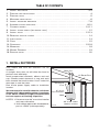
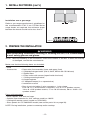
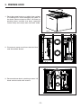
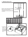
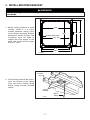
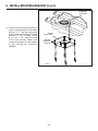
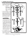
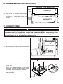
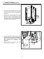
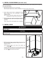
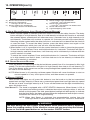
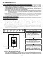
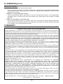
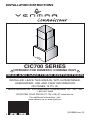
INSTALLATION INSTRUCTIONS
HB0119
CIC700 SERIES
!
INTENDED FOR DOMESTIC COOKING ONLY
!
READ AND SAVE THESE INSTRUCTIONS
INSTALLER: LEAVE THIS MANUAL WITH HOMEOWNER.
HOMEOWNER: USE AND CARE INFORMATION
ON PAGES 15 TO 18.
Venmar Ventilation Inc., 550 Lemire Blvd., Drummondville QC J2C 7W9
1-800-567-3855
REGISTER YOUR PRODUCT ON LINE AT: www.bnv.ca
For additional information, visit
www.venmar.ca or www.ispira.ca
SV09865 rev. 02
!
WARNING
!
WARNING
TO REDUCE THE RISK OF FIRE, ELECTRIC TO REDUCE THE RISK OF INJURY TO PERSONS
SHOCK OR INJURY TO PERSONS, OBSERVE IN THE EVENT OF A RANGE TOP GREASE
THE FOLLOWING:
FIRE, OBSERVE THE FOLLOWING*:
1.
Use this unit only in the manner intended by the
manufacturer. If you have questions, contact the
manufacturer at the address or telephone number
listed in the warranty.
2. Before servicing or cleaning unit, switch power off
at service panel and lock service disconnecting
means to prevent power from being switched on
accidentally. When the service disconnecting
means cannot be locked, securely fasten a prominent
warning device, such as a tag, to the service panel.
3. Installation work and electrical wiring must be done
by qualified personnel in accordance with all
applicable codes and standards, including
fire-rated construction codes and standards.
4. Sufficient air is needed for proper combustion and
exhausting of gases through the flue (chimney) of
fuel burning equipment to prevent backdrafting.
Follow the heating equipment manufacturer’s
guidelines and safety standards such as those
published by the National Fire Protection
Association (NFPA), and the American Society for
Heating, Refrigeration and Air Conditioning
Engineers (ASHRAE), and the local code authorities.
5. When cutting or drilling into wall or ceiling, do not
damage electrical wiring and other hidden utilities.
6. Ducted fans must always be vented to the outdoors.
7. Do not use this unit with any additional solid-state
speed control device.
8. To reduce the risk of fire, use only metal ductwork.
9. This unit must be grounded. To provide protection
against electric shock, connect to properly grounded
outlets only.
10. All tempered glass can experience spontaneous
breakage. If broken, tempered glass falls out of it’s
opening in interlocking clumps. Tempered glass
can, on occasion, break into large shards rather
than the classic tiny piece pattern.
11. When applicable local regulations comprise more
restrictive
installation
and/or
certification
requirements, the aforementioned requirements
prevail on those of this document and the installer
agrees to conform to these at his own expenses.
TO REDUCE THE RISK OF A RANGE TOP
GREASE FIRE:
a)
b)
c)
d)
Never leave surface units unattended at high
settings. Boilovers cause smoking and greasy
spillovers that may ignite. Heat oils slowly on low
or medium settings.
Always turn hood ON when cooking at high heat
or when flambeing food (i.e.: Crêpes Suzette,
Cherries Jubilee, Peppercorn Beef Flambé).
Clean ventilating fans frequently. Grease should
not be allowed to accumulate on fans, filters or
exhaust ducts.
Use proper pan size. Always use cookware
appropriate for the size of the surface element.
1.
SMOTHER FLAMES with a close-fitting lid,
cookie sheet or metal tray, then turn off the burner.
BE CAREFUL TO PREVENT BURNS. IF THE
FLAMES DO NOT GO OUT IMMEDIATELY,
EVACUATE AND CALL THE FIRE DEPARTMENT.
2.
NEVER PICK UP A FLAMING PAN – You may be
burned.
3.
DO NOT USE WATER, including wet dishcloths
or towels – This could cause a violent steam
explosion.
4.
Use an extinguisher ONLY if:
A. You own a Class ABC extinguisher and you
know how to operate it.
B. The fire is small and contained in the area
where it started.
C. The fire department has been called.
D. You can fight the fire with your back to an exit.
*Based on “Kitchen Fire Safety Tips” published by NFPA.
CAUTION
1.
2.
For indoor use only.
For general ventilating use only. Do not use to
exhaust hazardous or explosive materials and
vapors.
3. To avoid motor bearing damage and noisy and/or
unbalanced impeller, keep drywall spray, construction
dust, etc. off power unit.
4. Your hood motor has a thermal overload which will
automatically shut off the motor if it becomes
overheated. The motor will restart when it cools
down. If the motor continues to shut off and
restart, have the hood serviced.
5. The minimum hood distance above cooktop must
not be less than 30”. A maximum of 36” above
cooktop is highly recommended for best capture of
cooking impurities.
6. Two installers are recommended because of the
large size and weight of this hood.
7. To reduce the risk of fire and to properly exhaust
air, be sure to duct air outside – Do not exhaust air
into spaces within walls or ceiling or into attics,
crawl space or garage.
8. Because of the high exhausting capacity of this
hood, you should make sure enough air is
entering the house to replace exhausted air by
opening a window close to or in the kitchen.
9. To reduce the risk of fire and electrical shock, the
Venmar Connaisseur CIC700 Series models
should only be installed with their own built-in
blower.
10. Please read specification label on product for
further information and requirements.
-2-
TABLE OF CONTENTS
1. INSTALL DUCTWORK . . . . . . . . . . . . . . . . . . . . . . . . . . . . . . . . . . . . . . . . . . . . . . . .3-4
2. PREPARE THE INSTALLATION . . . . . . . . . . . . . . . . . . . . . . . . . . . . . . . . . . . . . . . . . . . .4
3. PREPARE HOOD . . . . . . . . . . . . . . . . . . . . . . . . . . . . . . . . . . . . . . . . . . . . . . . . . . . . .5
4. MEASURE INSTALLATION . . . . . . . . . . . . . . . . . . . . . . . . . . . . . . . . . . . . . . . . . . . . . . .6
5. INSTALL MOUNTING BRACKETS . . . . . . . . . . . . . . . . . . . . . . . . . . . . . . . . . . . . . . . . .7-8
6. ASSEMBLE ANGLE BRACKETS . . . . . . . . . . . . . . . . . . . . . . . . . . . . . . . . . . . . . . . . .9-10
7. CONNECT WIRING . . . . . . . . . . . . . . . . . . . . . . . . . . . . . . . . . . . . . . . . . . . . . . . .10-11
8. INSTALL GLASS PANELS (WG MODEL ONLY) . . . . . . . . . . . . . . . . . . . . . . . . . . . . . . . . .12
9. INSTALL HOOD . . . . . . . . . . . . . . . . . . . . . . . . . . . . . . . . . . . . . . . . . . . . . . . . . .12-13
10. REINSTALL BAFFLE FILTERS . . . . . . . . . . . . . . . . . . . . . . . . . . . . . . . . . . . . . . . . . . . .14
11. LIGHT BULBS . . . . . . . . . . . . . . . . . . . . . . . . . . . . . . . . . . . . . . . . . . . . . . . . . . . . . .14
12. CARE . . . . . . . . . . . . . . . . . . . . . . . . . . . . . . . . . . . . . . . . . . . . . . . . . . . . . . . . . . .15
13. OPERATION . . . . . . . . . . . . . . . . . . . . . . . . . . . . . . . . . . . . . . . . . . . . . . . . . . . .15-18
14. WARRANTY . . . . . . . . . . . . . . . . . . . . . . . . . . . . . . . . . . . . . . . . . . . . . . . . . . . . . . .18
15. WIRING DIAGRAM . . . . . . . . . . . . . . . . . . . . . . . . . . . . . . . . . . . . . . . . . . . . . . . . . .19
16. SERVICE PARTS . . . . . . . . . . . . . . . . . . . . . . . . . . . . . . . . . . . . . . . . . . . . . . . . . . . .20
1. INSTALL DUCTWORK
Plan where and how the ductwork will be
installed.
A straight, short duct run will allow the hood to
perform most efficiently.
Install proper-sized ductwork, elbows and roof
cap. Connect metal ductwork to cap and work
back towards the hood location. Use 2” metal foil
duct tape to seal the joints.
Run 3-wire power supply cable to installation
location.
We recommend to install the hood at a minimum
distance of 30” above cooking surface. A maximum
of 36” above cooktop is highly recommended
for best capture of cooking impurities.
NOTES: 1. Distances over 36” are at the installer
and users discretion.
2. 10-ft. ceilings require 10-ft. flue extension,
part no. 19325 (sold separately).
ROOF CAP
8" ROUND DUCT
DECORATIVE
FLUE
8" ROUND
ADAPTER/DAMPER
HOOD
30" TO 36" ABOVE
COOKING SURFACE
HH0153A
-3-
1. INSTALL DUCTWORK (CONT’D)
Installation over a gas range:
1" MIN.
Refer to gas range manufacturer’s guidelines for
the recommended CFM. If two CIC700 Series
range hoods are required, the minimum space
between the hoods should not be less than 1”.
HH0154A
2. PREPARE THE INSTALLATION
!
WARNING
When performing installation, servicing or cleaning the unit, it is recommended
to wear safety glasses and gloves.
NOTE: Before proceeding to the installation, check the contents of the box. If items are missing
or damaged, contact the manufacturer.
Make sure that the following items are included:
- Hood
- Accessories
•
•
•
•
•
•
•
•
•
Decorative flue assembly (lower and upper flues)
2 Shielded halogen bulbs (120 V, 50 W, MR16 with GU10 base)
2 Baffle filters
4 Filter knobs with screws (taped inside the hood)
1 Ceiling mounting bracket
8 Angle brackets
8” Adapter/Damper (in a separate box)
Installation manual
Bag of parts including: 2 wire connectors, 1 wire clamp,
8 no. 10 x 1½" wood screws, 8 washers, 2 no. 8 x 1/2" quadrex screws,
10 no. 8 x 3/8" quadrex screws, 17 no. 10-32 locknuts, 50 no. 10-32 x 1/2"
quadrex screws
Parts sold separately:
- Ducts, elbows, wall and roof caps.
- Optional flue extension for 10-ft. ceilings model no. 19325.
- LinkLogic® remote control (model no. ACW1WH).
- Glass panels for CIC700I16WG model (see service parts list on page 20).
NOTE: During installation, protect countertop and/or cooktop.
-4-
3. PREPARE HOOD
1. Rest the range hood on a table. Use a piece
of cardboard to avoid damaging the table or
the hood. Remove tape on filters. Lift filters by
pushing them towards the back (opposite
control side) and rotate, then set filters aside.
HO0194
2. Disconnect power cord from electrical box
and disconnect blower.
HE0125
SCREW
3. Remove blower box 4 retaining screws. Lift
hood and set aside with screws.
HD0433
-5-
LOCATIONS
4. MEASURE INSTALLATION
CEILING
C
BLOWER
BOX
BOTTOM
Determine angle brackets length needed
based upon ceiling height (B) and desired
height of hood above cooktop (A).
The table below indicates which flue(s) to use
and the number of brackets required according
to height (C).
RANGE HOOD
93⁄8"
BOTTOM
B
C = B - A - 93⁄8"
A
COOKTOP
HH0156A
C
FROM
TO
BRACKETS
14¾"
19½"
28¾"
33½"
40¾"
18¾"
28¼"
33"
40"
44¾"
4
8
8
12
12
REQUIRED COMPONENTS
UPPER LOWER OPTIONAL
FLUE
x
x
x
be,
* Ifbendneed
the 4 tabs
located in the
corners of the
top of the hood,
to a 45° angle
using a straightblade screwdriver
(as illustrated at
right).
45°
HD0445
-6-
FLUE
FLUE
x
x
x
x
x
x
BEND
TABS
x*
x*
5. INSTALL MOUNTING BRACKET
!
WARNING
When building framework, always follow all applicable construction codes and
standards.
10¼"
1. Modify ceiling stucture at hood
location. Install 2" x 4" cross
framing between ceiling joists
using ceiling mounting bracket
dimensions shown at right. The
framework must be sized to
support the total weight of the
hood and should not be larger
than 9¾" x 9¾".
10¼"
FRAMING
INNER EDGE
MAX. 9¾"
93⁄8 "
103⁄8 "
HK0062A
CEILING
JOISTS
2. Finish ceiling surface. Be sure to
mark the location of the ceiling
joists and cross framing. Bring
house wiring through finished
ceiling.
CROSS
FRAMING
HOUSE
WIRING
HD0432
-7-
93⁄8 " 103⁄8 "
5. INSTALL MOUNTING BRACKET (CONT’D)
8" ROUND
DUCTWORK
3. Position the mounting bracket in
such a way that one of the sides
without a “T” will be facing the
front of the hood. Secure mounting
bracket to the ceiling using
8 no. 10 x 1½" wood screws
(2 for each corner). Make sure
screws are driven into the center
of the framing for maximum
strength.
FRONT
OF THE HOOD
CEILING
MOUNTING
BRACKET
HD0442
-8-
6. ASSEMBLE ANGLE BRACKETS
1. Assemble 4 angle brackets to
the ceiling mounting bracket
using at least two no.10-32 x 1/2"
quadrex screws per angle bracket.
NOTES: 1. Do not tighten the
screws yet.
2. Depending on the
height needed (C)
(previously determined
in section 4), the
angle
brackets
might not touch the
ceiling as illustrated
at right.
2. If need be, assemble a second
set of 4 angle brackets to the
inner side of the upper angle
bracket set according to the
height needed (C) (previously
determined in section 4). Use at
least two no. 10-32 x 1/2" quadrex
screws and two no. 10-32 lock nuts
per angle bracket connection.
NOTE: Do not tighten the
screws yet.
FOR 10-FT
CEILINGS:
Both lower and upper flues are
included with the hood, but for
a 10-ft ceiling, discard the
provided upper flue and use
the optional extension flue, part
FOR 10-FT
CEILINGS
no. 19325 (sold separately).
(
IF NEED BE)
4 additional angle brackets and
additional mounting hardware
are included with the optional
extension flue.
If need be, assemble a third set
of 4 angle brackets to the second
angle bracket set according to the
height needed (C) (previously
FRONT
determined in section 4). Use
OF THE HOOD
at least two no. 10-32 x 1/2"
quadrex screws and two no. 10-32
lock nuts per angle bracket.
NOTE: Do not tighten the
screws yet.
3. Attach blower box assembly to
ELECTRICAL BOX
lower angle brackets using at least
two no. 10-32 x 1/2" quadrex
HD0444
screws per angle bracket.
NOTES: 1. Make sure the blower box bottom is at the desired height (C) as previously determined
in section 4.
2. Ensure electrical box is positioned in the back right corner.
-9-
6. ASSEMBLE ANGLE BRACKETS (CONT’D)
SIDE VIEWS
OF THE BLOWER BOX
FRONT
OF THE
CORRECT
HOOD
4. Make sure all brackets are straight
and blower box is level and square
(as shown at right), then tighten all
FRONT
screws.
OF THE
INCORRECT
HOOD
HD0420
7. CONNECT WIRING
!
WARNING
Risk of electric shock. Electrical wiring must be done by qualified personnel in
accordance with all applicable codes and standards. Before connecting wires,
switch power off at service panel and lock service disconnecting means to
prevent power to be switched on accidentally.
SCREW
1. Remove electrical box cover both retaining
screws. Set cover and screws aside.
HD0441
2. Install wire clamp (included) on top of
blower box.
Attach the adapter/damper to the blower
box using 4 no. 8 x 3/8" quadrex screws
(included). Remove tape on damper.
(Angle brackets not illustrated to ease
understanding).
HJ0068
- 10 -
LOCATIONS
7. CONNECT WIRING (CONT’D)
3. Run house wiring through wire clamp and
into blower box electrical box. Tighten wire
clamp to secure house wiring cable to
blower box.
4. Measure the required length of 8" round
metal duct from the adapter/damper to the
ductwork rough-in in the ceiling. Connect
this section of duct to the adapter/damper,
then connect to ceiling duct and seal both
joints with metal foil duct tape.
HOUSE
WIRING
HD0434
5. Connect hood power cable to house wiring
using provided wire connectors: BLACK to
BLACK, WHITE to WHITE and GREEN or
BARE wire to GREEN ground screw. DO
NOT FORGET TO CONNECT THE
GROUND.
6. Reinstall electrical box cover using both
screws previously removed.
HE0126
- 11 -
8. INSTALL GLASS PANELS (WG MODEL ONLY)
The WG hood model glass panels are sold separately and have to be installed before completing
the hood installation.
For each glass panel:
1. Remove glass panel from its packaging.
Remove glass panel nuts (factory installed) from both studs and set aside.
2. Insert glass panel studs in appropriate hood
holes (some parts not illustrated to ease
understanding).
NOTE: Install the glass panel with the control
pictograms on the front of the hood.
NUT
3. While holding glass panel, pre-tighten previously
removed nuts by hand. Ensure glass panel is
centered.
GLASS
PANEL
STUD
Then, using a 3/8" socket, tighten nuts completely.
9. INSTALL HOOD
HD0438
!
WARNING
BE CAREFUL when installing the decorative flue and hood, they may have
sharp edges.
CAUTION
DO NOT REMOVE the protective plastic film covering the decorative flue (upper
and lower) yet.
1
1. Slide the upper flue up to the ceiling and secure it to
the ceiling mounting bracket using 2 no. 8 x 1/2"
quadrex screws.
NOTE: Ensure upper and lower flue seams are
aligned 1 .
2
Carefully slide the lower flue over the upper flue up
to the ceiling and have the second person hold it to
the ceiling 2 while performing step 2.
- 12 -
HD0435
9. INSTALL HOOD (CONT’D)
SCREW
2. Slide hood over blower box and
attach to blower box using the
4 screws previously removed from
step 3.3 (some parts not illustrated to
ease understanding).
NOTE: For more convenience, a total of
16 holes (4 holes per section)
are available to secure the
hood, but only 1 screw per
section is necessary.
HD0433
3. Slide the lower flue down on top
of the hood. Remove protective
plastic film from flues.
HE0125
4. Connect blower and power cord back.
- 13 -
LOCATIONS
10.REINSTALL BAFFLE FILTERS
CAUTION
Remove protective plastic film covering filters before reinstalling them.
1. Using a Phillips no. 2 screwdriver, assemble
two knobs to each filter. The screws MUST
BE on filter tabs side. See illustration at
right.
HO0193
2. Rest rear filters edge on filter springs in
the range hood. Using knob, tilt up the filters into position. Make sure filter tabs are
securely engaged in range hood front
edge after installation.
FILTER TABS
HO0195
11. LIGHT BULBS
This range hood requires two 120 V, 50 W max., type MR16 with GU10 base, shielded halogen
bulbs (included).
!
WARNING
Do not touch lamps during or soon after operation. Burns may occur. In order
to prevent the risk of personal injury, only install shielded halogen lamps. Also,
never install a cool beam, a dichroïc lamp, a lamp not suitable for use in
recessed luminaires or identified for use in enclosed fixtures.
To replace bulbs:
1. Gently push upward and turn
counterclockwise to disengage bulb
leads from their grooves.
2. Place the new bulb leads into their
grooves in the socket.
3. Gently push upward and turn
clockwise until secured.
1
2
3
NOTE: If need be, use a rubber dishwashing glove to add grip when removing the bulb.
- 14 -
12. CARE
!
WARNING
Before servicing or cleaning the unit, switch power off at service panel and lock
service panel to prevent power from being switched on accidentally. When the
service disconnecting means cannot be locked, securely fasten a prominent
warning device, such as a tag, to the service panel.
BAFFLE FILTERS
Baffle filters should be cleaned monthly. Remove baffle filters by pushing them towards the back
of hood and rotating downward. Use a warm detergent solution to clean the filters. Let them dry
and reinstall them.
Baffle filters are dishwasher safe. Clean all-metal filters in the dishwasher using a non-phosphate
detergent. Discoloration of the filter may occur if using phosphate detergent or as a result of local
water conditions — but this will not affect filter performance. This discoloration is not covered by
the warranty.
INTERIOR BLOWER
Remove the filters in order to access the blower. Vacuum blower to clean. Do not immerse in water.
STAINLESS STEEL
Do:
• Regularly wash with clean cloth or rag
soaked with warm water and mild soap or
liquid dish detergent.
• Always clean in the direction of original polish
lines.
• Always rinse well with clear water (2 or 3
times) after cleaning. Wipe dry completely.
• You may also use a specialized household
stainless steel cleaner.
Don’t:
• Use any steel or stainless steel wool or any
other scrapers to remove stubborn dirt.
• Use any harsh or abrasive cleansers.
• Allow dirt to accumulate.
• Let plaster dust or any other construction
residues reach the hood. During
construction/renovation, cover the hood to
make sure no dust sticks to stainless steel
surface.
GLASS PANEL
Hot water with mild soap or glass cleaner is all that is usually needed.
When using mild soap, rinse with clear water. Wipe dry with a clean, soft cloth to avoid water
marks.
Avoid when choosing a detergent:
- Any cleaners that contain bleach will attack stainless steel.
- Any products containing: chloride, fluoride, iodide, bromide will deteriorate surfaces rapidly.
- Any combustible products used for cleaning such as acetone, alcohol, ether, benzol, etc., are
highly explosive and should never be used close to a range.
13. OPERATION
Always turn your blower on before you begin cooking to establish an air flow in the kitchen. Let the
blower run for a few minutes to clear the air after you turn off the range.
CAUTION
After a power failure or during the range hood power up, a 5-second booting
sequence is executed. Wait for the control backlighting to turn off before use.
NOTE: Due to the particular sensitivity of the control interface, keep the glass panel clean as dirt
and condensation may cause erratic operation of the hood blower and/or lighting. If this
situation occurs, wipe the glass panel and wait 90 seconds. Then, adjust the blower
and/or lighting at your convenience.
- 15 -
13. OPERATION (CONT’D)
A
B
E
D
C
F
G
HC0052
A)
B)
C)
Blower Delay/Control Lock button
Blower low speed button
— LinkLogic® Erase Link button
Blower medium-low speed button
— LinkLogic® Master Link Mode button
D)
Blower medium-high speed button
— LinkLogic® Auto Link Mode button
E) Blower high speed button
— LinkLogic® Activate/Exit Link Mode button
F) Master ON/OFF button
G) Light/Backlighting Color button
A. DELAY BUTTON/CONTROL LOCK (DOUBLE FUNCTION BUTTON):
i. When a blower speed is selected, press this button to activate the delay function. The delay
button will light to its high intensity, then to its mid intensity to indicate this function is activated;
the selected blower speed button will alternate every 2 seconds from its high intensity to its
mid intensity. The blower will continue to operate for 5 minutes and will stop automatically.
Selecting another speed while the delay function is activated will not deactivate the function
or reset the timer. To cancel the delay function, press the delay button once again or the
selected speed button which last case will also turn the blower off.
ii. When blower is off, it is possible to lock the control interface in order to clean the glass panel.
To lock the control interface: Press and hold the button for 3 seconds. The button will light to
its high intensity and flash three times, it will then stay on its mid intensity to indicate that the
control interface is locked.
To unlock the control interface: Press and hold the button for 3 seconds. The button will light
to its high intensity and flash 3 times, it will then fade out to its low intensity to indicate that
the control interface is unlocked.
B-E. SPEED SELECTION BUTTONS:
Press the button corresponding to the desired blower speed (from 1 for low speed to 4 for high
speed). The chosen speed button will light to its high intensity then fade to its mid intensity. To
turn off the blower, press once more on the corresponding blower speed button; the button light
will fade to its low intensity.
NOTE: When blower is off, pressing on blower speed 1 button will cause the blower to start on
second speed for a very short lapse of time, and then resume on speed 1.
F. MASTER ON/OFF:
When blower and lights are off, press this button to turn the hood on to the last memorized
speed level and light intensity. If there are no memorized speed level and light intensity, speed
will be set at level 1 and light intensity at 4. To turn off the blower and the light simultaneously,
press this button once.
HEAT SENTRY™: The hood is equipped with a HEAT SENTRY thermostat. When blower is ON at
any speed and excessive heat is detected above the cooking surface, it sets the
blower on third speed. The third speed button backlight will blink quickly to indicate
that the Heat Sentry has been activated. When the temperature level drops to normal,
the blower will return to its original setting.
NOTE: When Heat Sentry is activated, the communication coming from the
LinkLogic device is disabled and the “DELAY OFF” function is inactivated.
!
WARNING
The Heat Sentry can take control of the blower when excessive heat is detected
above the cooking surface. If this situation occurs and you must stop the blower,
press on the third speed button or on the master ON/OFF button.
- 16 -
13. OPERATION (CONT’D)
G. LIGHT BUTTON/BACKLIGHTING COLOR (DOUBLE FUNCTION BUTTON):
i. This button allows four different lighting levels according to your needs. Press once for full
intensity, twice for intensity level 3, three times for intensity level 2 and once more for
nightlight. To turn off the lights, press once more.
If desired, when the lights are on, press and maintain the light button for 1 second; lights will
be turned off and the light level in use will be memorized.
NOTE: When only lights are ON to any intensity and no interaction with the hood is detected
for a 10-second period, the 7 buttons backlighting will fade to its low intensity, acting
as a night light feature.
ii. When lights are off, pressing and holding this button for 2 seconds will switch the backlighting
color from white to blue or from blue to white (default backlighting color is white) and memorize
it. The button will flash three times to indicate that the color change has been made.
LINKLOGIC® NETWORK
COMPATIBILITY
Your CIC700I16 Series range hood can be linked to LinkLogic network, if installed in your house.
LINKLOGIC® LINKING INSTRUCTIONS
1.INITIALIZE THE LINKLOGIC DEVICE TO BE LINKED
Lift and release the Set button tab, then push it for 3 seconds or until “beep” is heard. When
the tab is released the remote control, confirms initialization by turning ON the backlight of
the “Room Light ON and Off” button. Press the “Room Light OFF” button to stop the
flashing. Initialization of the remote control is now completed.
2.ACTIVATE THE LINK MODE OF THE RANGE HOOD
Push and hold button E for 3 seconds. After the 3-second hold, button E backlight blinks
3 times quickly (low to high intensity) and then all 4 speed levels backlights start to oscillate
between mid and low intensity.
LINK
A
B
C
D
E
F
G
FOR LINKLOGIC™
MODEL NO. ACW1WH
HC0052
ACTIVATE THE LINK MODE
OF THE LINKLOGIC® DEVICE
Push the Light Off button of the
LinkLogic device for 10 seconds or
until its backlight flashes
(“beep” should also be heard).
ROOM LIGHT
ON
START THE AUTO-LINK
PROCESS
OF THE RANGE HOOD
FAN
LIGHT
FAN
OFF
LIGHT
OFF
Press and release button D to start
the Auto-link process, all 4 speed
level backlights flash in rotation.
ROOM LIGHT
OFF
SET
LINK OF ANOTHER LINKLOGIC® DEVICE
Go back to the appropriate first step if
another LinkLogic device
needs to be linked.
Otherwise, to exit Link mode, go to:
Exit the Link mode of the range hood
BUTTON
HC0053
3.EXIT THE LINK MODE OF THE RANGE HOOD
Press and hold button E for 3 seconds. After the 3-second hold, button E backlight blinks
3 times quickly (low to high intensity) and it exits the Link mode. Link mode remains activated
for 4 minutes if no other operation is done.
- 17 -
13. OPERATION (CONT’D)
ERASE LINK PROCESS
1.ACTIVATE THE LINK MODE OF THE RANGE HOOD
Push and hold button E for 3 seconds. After the 3-second hold, button E backlight blinks
3 times quickly (low to high intensity) and then all 4 speed levels backlights start to oscillate
between mid and low.
2.ERASE ALL LINKED LINKLOGIC DEVICES
Push and hold button B for 3 seconds to start the “Erase-link” process, all 4 speed levels
backlights flash in rotation until links are erased (not visible when small number of linked
devices).
3.EXIT THE LINK MODE OF THE RANGE HOOD
Press and hold button E for 3 seconds. After the 3-second hold, button E backlight blinks
3 times quickly (low to high intensity) and it exits the Link mode. Link mode remains activated
for 4 minutes if no other operation is done.
14.WARRANTY
VENMAR VENTILATION FIVE-YEAR WARRANTY
Venmar Ventilation Inc. warrants to the original consumer purchaser of the Venmar Connaisseur
CIC700 Series range hood that such product will be free from defects in materials or workmanship for
a period of five (5) years from date of original purchase. This warranty includes in-home service for the
first year and workshop service for the four (4) remaining years.
THERE ARE NO OTHER WARRANTIES, EXPRESS OR IMPLIED, INCLUDING, BUT NOT LIMITED
TO, IMPLIED WARRANTIES OF MERCHANTABILITY OR FITNESS FOR A PARTICULAR PURPOSE.
VENMAR VENTILATION INC. WILL NOT BE HELD RESPONSIBLE FOR ANY CLAIMS OVER THE
ORIGINAL PURCHASE PRICE OF A VENMAR CONNAISSEUR CIC700 SERIES RANGE HOOD
NOR HELD RESPONSIBLE FOR SUBSEQUENT DAMAGE OR INCIDENT.
During the period stated above, Venmar Ventilation Inc. will, at its option, repair or replace without
charge any product or part which is found to be defective under normal use and service. THIS
WARRANTY DOES NOT EXTEND TO ANY LIGHT BULBS AND FILTERS.
This warranty does not cover a) normal maintenance and service b) any products or parts which have
been subject to misuse, negligence, accident, improper maintenance or repairs made by other than
Venmar Ventilation Inc., or c) a faulty installation or installation contrary to recommended installation
instructions.
Warranty service is to be completed by an authorized Service Center designated by Venmar Ventilation
Inc. Where applicable, in-home service will be made available only in areas where a contracted
service provider offers service. If in-home service is not available, the product will be repaired or
replaced, at Venmar’s discretion, by the nearest authorized service provider. The unit removal and
reinstallation works are under the customer responsibility, and Venmar cannot be charged for them.
The duration of any implied warranty is limited to the 5-year period as specified for the express
warranty. Some provinces do not allow limitation on how long an implied warranty lasts, so the above
limitation may not apply to you.
VENMAR VENTILATION INC'S OBLIGATION TO REPAIR OR REPLACE AT VENMAR
VENTILATION INC'S OPTION, SHALL BE THE PURCHASER'S SOLE AND EXCLUSIVE
REMEDY UNDER THIS WARRANTY. VENMAR VENTILATION INC SHALL NOT BE LIABLE FOR
INCIDENTAL, CONSEQUENTIAL OR SPECIAL DAMAGES ARISING OUT OF OR IN CONNECTION
WITH PRODUCT USE OR PERFORMANCE. SOME PROVINCES DO NOT ALLOW THE
EXCLUSION OR LIMITATION OF INCIDENTAL OR CONSEQUENTIAL DAMAGES, SO THE ABOVE
LIMITATION OR EXCLUSION MAY NOT APPLY TO YOU.
This warranty gives you specific legal rights and you may also have other rights, which vary from
province to another. This warranty supersedes all prior warranties.
To contact Venmar Ventilation Inc. warranty service call 1-800-567-3855 in Canada. In order to qualify
for a warranty claim, the owner of a Venmar Connaisseur CIC700 Series range hood must have the
model and serial number along with a proof of the original purchase date. At the time of requesting
service, describe the nature of any defect in the product or part.
Venmar Ventilation Inc., 550 Lemire Blvd., Drummondville, QC J2C 7W9 (1-800-567-3855)
www.venmar.ca
www.ispira.ca
- 18 -
- 19 -
RED
WHITE
YELLOW
RED
WHT
YEL
HE0127A
BLACK
BLUE
BROWN
GREY
ORANGE
BLK
BLU
BRN
GRY
ORG
COLOR CODE
120 VAC
LINE
GROUND
NEUTRAL
USER INTERFACE
J8
BLK
HIGH
WHT
NEUTRAL
LINE
LINE
J5
J6
1
MED HIGH
1
2
3
1
2
3
2
J4
3
MED LOW
LAMP
4
LOW
CONTROL BOARD
WHT
BLK
BLK
ORG
WHT
BLU
BLK
YEL
BLK
LAMP
YEL
BLK
ORG
WHT
BLU
RED
WHT
WHT
YEL
FAN MOTOR
LAMP
BRN
GRY
WHT
25 µF
WHT
15.WIRING DIAGRAM
16.SERVICE PARTS
1
2
15
3
4
REPLACEMENT PARTS
14
6
5
7
13
8
9
10
11
12
HL0158
KEY
NO.
PART
NO.
1
2
3
4
5
6
7
8
9
10
11
12
13
14
15
*
*
SV19232
SV19240
SV19239
SV08543
SV09958XX**
SV09552
SV09550
SV05917
SV09435
SV09434
SV05921
SV19249
SV09959XX**
SV08582
SV19253
SV08967
SV09865
*
SV09871
*NOT
REPAIRS
DESCRIPTION
CEILING
MOUNTING BRACKET
UPPER DECORATIVE FLUE
LOWER DECORATIVE FLUE
8” ROUND ADAPTER/DAMPER
FRONT GLASS PANEL WITH CONTROL PICTOGRAM
POWER UNIT
ELECTRONIC CONTROL
SOCKET
SOCKET HOLDER
LIGHT TRIM
SHIELDED HALOGEN BULB (120 V, 50 W, GU10)
BAFFLE FILTERS 13.56” X 5.06” X 0.625” (KNOBS AND SCREWS INCLUDED)
BACK GLASS PANEL WITHOUT CONTROL PICTOGRAM
INTERNAL BLOWER (INCLUDING CAPACITOR)
ANGLE BRACKETS (SET OF 8)
KNOBS AND SCREWS KIT (2 KNOBS AND SCREWS PER KIT)
INSTALLATION GUIDE
PARTS BAG: 2 WIRE CONNECTORS, 1 WIRE CLAMP, 8 WASHERS, 8 X NO. 10 X 1½"
WOOD SCREWS, 2 X NO. 8 X 1/2" QUADREX SCREWS, 10 X NO. 8 X 3/8" QUADREX
SCREWS, 17 X NO. 10-32 LOCKNUTS, 50 X NO. 10-32 X 1/2" QUADREX SCREWS
SHOWN.
**PART
AND
In order to ensure your unit remains
in good working condition, you must
use Venmar Ventilation Inc. genuine
replacement parts only. Venmar
Ventilation Inc. genuine replacement
parts are specially designed for
each unit and are manufactured to
comply with all the applicable
certification standards and maintain
a high standard of safety. Any third
party replacement part used may
cause serious damage and drastically
reduce the performance level of
your unit, which will result in premature
failing. Venmar Ventilation Inc.
recommends to contact a certified
service depot for all replacement
parts and repairs.
NUMBER ACCORDING TO GLASS PANEL COLOR.
- 20 -
QTY.
1
1
1
1
1
1
1
2
2
2
2
2
1
1
1
2
1
1