1
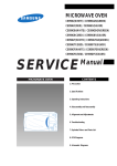
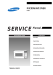
MICROWAVE OVEN
CE118KFR
SERVICE
Manual
CONTENTS
MICROWAVE OVEN
1. Precaution
2. Specifications
3. Operating Instructions
4. Disassembly and Reassembly
5. Alignment and Adjustments
6. Troubleshooting
7. Exploded Views and Parts List
8. PCB Diagrams
9. Schematic Diagrams
BWT
ELECTRONICS
© Samsung Electronics Co., Ltd. December 1997
Printed in Korea
DE68-62334A
PRECAUTIONS TO BE OBSERVED BEFORE AND DURING
SERVICING TOAVOID POSSIBLE EXPOSURE TO EXCESSIVE
MICROWAVE ENERGY
(a) Do not operate or allow the oven to be
operated with the door open.
(b) Make the following safety checks on
all ovens to be serviced before
activating the magnetron or other
microwave source, and make repairs as
necessary:
(1) Interlock operation,
(2) proper door closing,
(3) seal and sealing surfaces (arcing,
wear, and other damage),
(4) damage to or loosening of hinges
and latches,
(5) evidence of dropping or abuse.
(c) Before turning on microwave power
for any service test or inspection
within the microwave generating
compartments, check the magnetron,
wave guide or transmission line, and
cavity for proper alignment, integrity,
and connections.
(d) Any defective or misadjusted
components in the interlock, monitor,
door seal, and microwave generation
and transmission systems shall be
repaired, replaced, or adjusted by
procedures described in this manual
before the oven is released to the
owner.
(e) A Microwave leakage check to verify
compliance with the Federal
performance standard should be
performed on each oven prior to
release to the owner.
Samsung Electronics
1. Precaution
Follow these special safety precautions. Although the microwave oven is completely safe during ordinary
use, repair work can be extremely hazardous due to possible exposure to microwave radiation, as well as
potentially lethal high voltages and currents.
1-1 Safety precautions (
)
1. All repairs should be done in accordance
with the procedures described in this
manual. This product complies with
Federal Performance Standard 21 CFR
Subchapter J (DHHS).
SESPO
SAMSUNG ELECTRONICS CO.,LED
ST.PETERSBERG OFFICE
5.1TALIANSKAYASTR.
ST.PETERSBERG,191011,RUSSIA
SALSC
2. Microwave emission check should be
performed to prior to servicing if the oven is
operative.
3. If the oven operates with the door open :
Instruct the user not to operate the oven and
contact the manufacturer and the center for
devices and radiological health immediatly.
4. Notify the Central Service Center if the
microwave leakage exceeds 5 mW/cm2
5. Check all grounds.
6. Do not power the MWO from a "2-prong"
AC cord. Be sure that all of the built-in
protective devices are replaced. Restore any
missing protective shields.
7. When reinstalling the chassis and its
assemblies, be sure to restore all protective
devices, including: nonmetallic control
knobs and compartment covers.
8. Make sure that there are no cabinet openings
through which people--particularly
children--might insert objects and contact
dangerous voltages. Examples: Lamp hole,
ventilation slots.
9. Inform the manufacturer of any oven found
to have emmission in excess of 5 mW/cm2,
Make repairs to bring the unit into
compliance at no cost to owner and try to
determine cause.
Instruct owner not to use oven until it has
been brought into compliance.
SUSC
SAMSUNG ELECTRONICS SERVICE CO.LTD
7 ZHILIYANSKAYA STREET.
KIEV 252033.UKRAINE
SMSC
"JV SAMSUNG SERVICE" LTD
RUSSIA,123308 MOSCOW,MARSHALA
ZHUKOVAPR,1,OFFICE 201
Samsung Electronics
SAMSUNG ALMATY SVC CO.
52A MICROREGION ORIBITA-3
ALMATY.480043 REPUBIC OF
KAZAHSTAN
10. Service technicians should remove their
watches while repairing an MWO.
11. To avoid any possible radiation hazard,
replace parts in accordance with the wiring
diagram. Also, use only the exact
replacements for the following parts:
Primary and secondary interlock switches,
interlock monitor switch.
12. If the fuse is blown by the Interlock Monitor
Switch: Replace all of the following at the
same time: Primary and secondary switches,
as well as the Interlock Monitor Switch. The
correct adjustment of these switches is
described elsewhere in this manual. Make
sure that the fuse has the correct rating for
the particular model being repaired.
13. Design Alteration Warning:
Use exact replacement parts only, i.e.,
only those that are specified in the
drawings and parts lists of this manual.
This is especially important for the
Interlock switches, described above.
Never alter or add to the mechanical or
electrical design of the MWO. Any design
changes or additions will void the
manufacturer's warranty.10.Always unplug
the unit's AC power cord from the AC
power source before attempting to
remove or reinstall any component or
assembly.
14. Never defeat any of the B+ voltage
interlocks. Do not apply AC power to the
unit (or any of its assemblies) unless all
solid-state heat sinks are correctly installed.
1-1
Pretaution
1-2 Special Servicing Precautions (Continued)
15. Some semiconductor ("solid state") devices
are easily damaged by static electricity. Such
components are called Electrostatically
Sensitive Devices (ESDs). Examples include
integrated circuits and field-effect
transistors.
Immediately before handling any
semiconductor components or assemblies,
drain the electrostatic charge from your
body by touching a known earth ground.
16. Always connect a test instrument's ground
lead to the instrument chassis ground before
connecting the positive lead; always remove
the instrument's ground lead last.
17. When checking the continuity of the
switches or transformer, always make sure
that the power is OFF, and one of the lead
wires is disconnected.
18. Components that are critical for safety are
indicated in the circuit diagram by
shading,
or
.
19. Use replacement components that have the
same ratings, especially for flame resistance
and dielectric strength specifications. A
replacement part that does not have the
same safety characteristics as the original
might create shock, fire or other hazards.
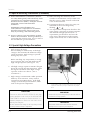
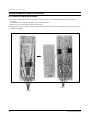
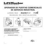
1-3 Special High Voltage Precautions
1. High Voltage Warning
Do not attempt to measureany of the high
voltages--this includes the filament voltage
of the magnetron. High voltage is present
during any cook cycle.
Before touching any components or wiring,
always unplug the oven and discharge the
high voltage capacitor (See Figure 1-1)
2. The high-voltage capacitor remains charged
about 30 seconds after disconnection. Short
the negative terminal of the high-voltage
capacitor to the oven chassis. (Use a
screwdriver.)
3. High voltage is maintained within specified
limits by close-tolerance, safety-related
components and adjustments. If the high
voltage exceeds the specified limits, check
each of the special components.
¢
: Touch chassis side first then short to the high voltage
capacitor terminal by using a screwdriver or jumper
wire.
PRECAUTION
PRECAUTION
There exists HIGH VOLTAGE ELECTRICITY with high
current capabilities in the circuits of the HIGH VOLTAGE
TRANSFORMER secondary and filament terminals. It is
extremely dangerous to work on or near these circuits
with the oven energized.
DO NOT measure the voltage in the high voltage circuit
including filament voltage of magnetron.
Never touch any circuit wiring with your hand nor with an
insulated tool during operation.
1-2
PRECAUTION
Servicemen should remove their watches whenever
working close to or replacing the magnetron.
Samsung Electronics
2. Specifications
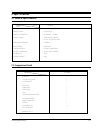
2-1 Table of Specifications
MODEL
ITEM
CE118KFR
TIMER
99 MINUTES 90 SECONDS
POWER SOURCE
230V/50HZ, AC
POWER CONSUMPTION
MICROWAVE : 1,500W
OUTPUT POWER
900W (10LEVEL POWER)
(IEC-705 TEST PROCEDURE)
OPERATING FREQUENCY
2,450MHz
MAGNETRON
OM75PH(31)
COOLING METHOD
COOLING FAN MOTOR
OUTSIDE DIMENSIONS
547(W) x 339(H) x 528(D)
NET WEIGHT
26 Kg
SHIPPING WEIGHT
30 Kg
2-2 Comparison Chart
MODE
CE118KFR
MORE/LESS
¡
AUTO REHEAT/COOK
¡
AUTO DEFROST
¡
TIME COOK
¡
POWER LEVEL
¡
CONVECTION
¡
GRILL
¡
MICROWAVE+CONVECTION
¡
MICROWAVE+GRILL
¡
CONVECTION+GRILL
¡
PREHEAT
¡
DIODORIZATION
X
CRUSTY REHEAT
¡
BARBECUE SPIT
¡
Samsung Electronics
2-1
3. Operating Instructions
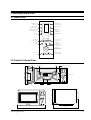
3-1 Control Panel
Razogrev
Uroven; mo]nosti
PREHEAT/GRILL+OVEN
MODE SELECTION
MICROWAVE/POWER
LEVEL MODE SELECTION
Gril;+ Peh;
Peh; / S
Gril;
CONVECTION MODE/
TEMPERATURE SELECTION
GRILL MODE SELECTION
SVH + Peh;
SVH + Gril;
COMBINED MODE
SELECTION
(MICROWAVE+GRILL)
COMBINED MODE SELECTION
(MICROWAVE+CONVECTION)
Avtopodogrev
1.Napitki
2.Lomtiki mqsa
3.Sup/Sous
CLOCK SETTING
CRUSTY REHEAT COOK
SELECTION
Avtoprigotovlenie pi]i
4.Ohi]ennyj kartofel;
5.Sve’ie ovo]i
6.Sve’aq ryba
7."arenaq kurica
8."arenaq govqdina
9."arenaq svinina
10.Tort
azm orozka
A vtor
1.Picca
2.Pehenye hipsy
3.Pirog
ev i
A vtopodogr prigotovlen
ie
AUTO REHEAT & COOK
FEATURE SELECTION
AUTO DEFROST
FEATURE SELECTION
Zader’ka/Pauza
Pamqt;
Bol;we/Men;we
COOKING TIME
ADJUSTMENT BUTTONS
STANDING TIME
SETTING
MEMORY COOK
FEATURE SELECTION
TIME SETTING,
WEIGHT SELECTION AND
SERVING SELECTION
STOP BUTTON
START/COOKING TIME
ADJUSTMENT BUTTONS
1min+
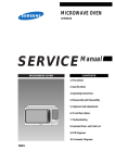
3-2 Features & External Views
Door
Ventilation Slot
Light
Safety Interlock Holes
,,,,,,,,,,,,,,,,,
,,,,,,,,,,,,,,,,,
,,,,,,,,,,,,,,,,,
,,,,,,,,,,,,,,,,,
,,,,,,,,,,,,,,,,,
,,,,,,,,,,,,,,,,,
,,,,,,,,,,,,,,,,,
,,,,,,,,,,,,,,,,,
,,,,,,,,,,,,,,,,,
,,,,,,,,,,,,,,,,,
,,,,,,,,,,,,,,,,,
,,,,,,,,,,,,,,,,,
,,,,,,,,,,,,,,,,,
,,,,,,,,,,,,,,,,,
,,,,,,,,,,,,,,,,,
,,,,,,,,,,,,,,,,,
,,,,,,,,,,,,,,,,,
,,,,,,,,,,,,,,,,,
,,,,,,,,,,,,,,,,,
,,,,,,,,,,,,,,,,,
,,,,,,,,,,,,,,,,,
,,,,,,,,,,,,,,,,,
,,,,,,,,,,,,,,,,,
,,,,,,,,,,,,,,,,,
,,,,,,,,,,,,,,,,,
,,,,,,,,,,,,,,,,,
,,,,,,,,,,,,,,,,,
,,,,,,,,,,,,,,,,,
,,,,,,,,,,,,,,,,,
,,,,,,,,,,,,,,,,,
,,,,,,,,,,,,,,,,,
,,,,,,,,,,,,,,,,,
,,,,,,,,,,,,,,,,,
,,,,,,,,,,,,,,,,,
,,,,,,,,,,,,,,,,,
,,,,,,,,,,,,,,,,,
,,,,,,,,,,,,,,,,,
,,,,,,,,,,,,,,,,,
,,,,,,,,,,,,,,,,,
Control Panel
Glass Plate
Guide Roller
339mm
Door Latches
225mm
547mm
Samsung Electronics
528mm
3-1
4. Disassembly and Reassembly
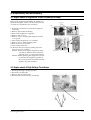
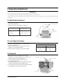
4-1 Replacement of Magnetron, Motor Assembly and Lamp
Remove the magnetron including the shield case,
permanent magnet, choke coils and capacitors (all
of which are contained in one assembly).
1. Disconnect all lead wires from the magnetron
and lamp.
2. Remove the bracket mounting.
3.Remove the magnetron supporter
4. Remove the air cover.
5. Remove screws securing the magnetron to the
wave guide.
6. Take out the magnetron very carefully.
7. Remove screws from the back panel.
8.Remove the assy noise filter.
9. Take out the fan motor.
10. Remove the oven lamp by pulling out from
hole of air cover carefully.
NOTE1: When removing the magnetron, make
sure that its antenna does not hit any
adjacent parts, or it may be damaged.
NOTE2: When replacing the magnetron, be sure
to remount the magnetron gasket in
the correct position and make sure the
gasket is in good condition.
Cover Air
Thermo S/W
Lamp
Fan Motor
Magnetron H. V. Trans
H. V. Capacitor
Screw
4-2 Replacement of High Voltage Transformer
1. Discharge the high voltage capacitor.
2. Disconnect all the leads.
3. Remove the mounting bolts.
4. Reconnect the leads correctly and firmly.
H. V. Trans
Screws
Samsung Electronics
4-1
Disassembly and Reassembly
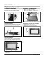
4-3 Replacement of Door Assembly
4-3-4 Removal of Key Door & Spring
4-3-1 Removal of Door Assembly
Remove screws securing the upper hinge and
lower hinge. Then remove the door assembly.
Remove pin hinge from Door "E"
Detach spring from Door "E" and key door.
Upper Hinge
Spring
Door "E"
Screw
Key Door
Lower Hinge
Screw
4-3-2 Removal of Door "C"
4-3-5 Removal of Screen-Door & Sub-Door
Insert flat screwdriver into the gap between Door
"A" and Door "C" to remove Door "C". Be careful
when handling Door "C" because it is fragile.
1. Remove Door"E" from Door"A".
2. Remove Door-Screen"B" and Sub Door.
Door-Sub
Door "A"
Door "C"
4-3-3 Removal of Door "E"
Following the procedure as shown in the figure,
insert and bend a thin metal plate between Door
"E" and Door "A" until you hear the 'tick' sound.
Door "E"
1. Insertion depth of the thin metal plate should be
0.5mm or less.
4-2
Samsung Electronics
Disassembly and Reassembly
4-3-5 Reassembly Test
After replacement of the defective component parts of the door, reassemble it and follow the instructions below for proper
installation and adjustment so as to prevent an excessive microwave leakage.
1. When mounting the door to the oven, be sure to adjust the door parallel to the bottom line of the oven
face plate by moving the upper hinge and lower hinge in the direction necessary for proper alignment.
2. Adjust so that the door has no play between the inner door surface and oven front surface. If the door
assembly is not mounted properly, microwave energy may leak from the space between the door and
oven.
3. Do the microwave leakage test.
4-4 Replacement of Fuse
1. Disconnect the oven from the power source.
2. Remove the 10A fuse in the Noise filter.
3. When replacing the 10A fuse, be sure to use an
exact replacement part. If new 10A fuse blows
out again after replacement, check the primary
interlock switch, door sensing switch and
interlock monitor switch.
4. When the above three switches operate properly,
check if any other part such as the control circuit
board, blower motor or high voltage
transformer is defective.
4-5 Replacement of Drive Motor
1. Take out the glass tray and guide roller from the
cavity.
2. Turn the oven upside down to replace the drive motor.
3. Remove a screw securing the drive motor cover.
Drive Motor
Screw
4. Disconnect all the lead wires from the drive motor.
5. Remove screws securing the drive motor to the
cavity.
6. Remove the drive motor and coupler.
Thermo
Switch
7. When replacing the drive motor, be sure to
remount it in the correct position with the
coupler.
8. Connect all the leads to the drive motor.
Drive Motor Cover
Base Plate
9. Screw the drive motor cover to the base plate
with a screw driver.
Samsung Electronics
4-3
Disassembly and Reassembly
4-6 Replacement of Control Circuit Board
4-6-1 Removal of Control Box Assembly
1. Be sure to disclyarge any static electricity from your body, and avoid touching the "Touch control"
clrcuitry.
2. Disconnect the connectors from the control circuit board.
3. Remove screws securing the control circuit bord.
4. Lift up the control circuit board from right side and remove the hooks holding the contol circuit board to
the box assembly.
Screws
Screws
4-4
Samsung Electronics
5. Alignment and Adjustments
PRECAUTION
1. High voltage is present at the high voltage terminals during any cook cycle.
2. It is neither necessary nor advisable to attempt measurement of the high voltage.
3. Before touching any oven components or wiring, always unplug the oven from its power source and discharge the high voltage
capacitor.
5-1 High Voltage Transformer
1. Remove connectors from the transformer terminals
and check continuity.
2. Normal resistance readings are as follows:
H.V.T SPEC.
Secondary
Filament
Primary
Filament Terminals
SHV-945EGI-AC-2
86W ¡ 10%
Shows Continuity
1.5W ¡ 10%
(Room temperature = 20ûC)
Primary
Terminals
5-2 Low Voltage Transformer
1. The low voltage transformer is located on the
control circuit board.
2. Remove the low voltage transformer from the
PCB Ass'y and check continuity.
3. Normal resistor reading is shown in the table.
L.V.T SPEC. : SLV-105E
Terminals
Resistance
1~2(Input)
3~4(Output)
5~6(Output)
290W
4.0W
1.0W
5-3 Magnetron
Continuity checks can indicate only an open
filament or a shorted magnetron. To diagnose an
open filament or shorted magnetron :
1. Isolate the magnetron from the circuit by
disconnecting its leads.
2. A continuity check across the magnetron filament
terminals should indicate one ohm or less.
3. A continuity check between each filament terminal
and magnetron case should read open.
Magnetron Antenna
Gasket Plate
Cooling Fins
Samsung Electronics
5-1
Alignment and Adjustments
5-4 High Voltage Capacitor
1. Check continuity of the capacitor with the meter set at the highest resistance scale.
2. Once the capacitor is charged, a normal capacitor shows continuity for a short time, and then indicates 9MW.
3. A shorted capacitor will show continuous continuity.
4. An open capacitor will show constant 9MW.
5. Resistance between each terminal and chassis should read infinite.
5-5 High Voltage Diode
1. Isolate the diode from the circuit by disconnecting its leads.
2. With the ohm-meter set at the highest resistance scale, measure across the diode terminals. Reverse the
meter leads and read the resistance. A meter with 6V, 9V or higher voltage batteries should be used to
check the front-to back resistance of the diode (otherwise an infinite resistance may be read in both
directions). The resistance of a normal diode will be infinite in one direction and several hundred KW in
the other direction.
5-6 Main Relay and Power Control Relay
1. The relays are located on the PCB Ass'y. Isolate them from the main circuit by disconnecting the leads.
2. Operate the microwave oven with a water load in the oven. Set the power level set to high.
3. Check continuity between terminals of the relays after the start pad is pressed.
5-7 Adjustment of Primary Switch, Door Sensing Switch and Monitor Switch
Precaution
For continued protection against radiation hazard, replace parts in accordance with the wiring diagram and be sure to use the
correct part number for the following switches: Primary and door sensing switches, and the interlock monitor switch (replace all
together). Then follow the adjustment procedures below. After repair and adjustment, be sure to check the continuity of all
interlock switches and the interlock monitor switch.
1. When mounting Primary switch and Interlock
Monitor switch to Latch Body, consult the
figure.
NOTE:No specific adjustment during
installation of Primary switch and Monitor
switch to the latch body is necessary.
Primary Switch
2. When mounting the Latch Body to the oven
assembly, adjust the Latch Body by moving it so
that the oven door will not have any play in it.
Check for play in the door by pulling the door
assembly. Make sure that the latch keys move
smoothly after adjustment is completed.
Completely tighten the screws holding the Latch
Body to the oven assembly.
Body Latch
Interlock
Monitor
Switch
Lever Door
3. Reconnect to Monitor switch and check the
continuity of the monitor circuit and all latch
switches again by following the components test
procedures.
4. Confirm that the gap between the switch
housing and the switch actuator is no more than
0.5mm when door is closed.
5-2
Door Sensing
Switch
Primary switch
Monitor switch (COM-NC)
Monitor switch (COM-NO)
Door Sensing S/W
Door Open
¥
0
¥
¥
Door Closed
0
¥
0
0
Samsung Electronics
Alignment and Adjustments
5-8 Output Power of Magnetron
CAUTION
MICROWAVE RADIATION
PERSONNEL SHOULD NOT ALLOW EXPOSURE TO MICROWAVE RADIATION FROM MICROWAVE GENERATOR OR OTHER PARTS
CONDUCTING MICROWAVE ENERGY.
The output power of the magnetron can be measured by performing a water temperature rise test.
Equipment needed :
* Two 1-liter cylindrical borosilicate glass vessel (Outside diameter 190 mm)
* One glass thermometer with mercury column
NOTE: Check line voltage under load. Low voltage will lower the magnetron output. Make all temperature
and time tests with accurate equipment.
1. Fill the one liter glass vessel with water.
2. Stir water in glass vessel with thermometer, and record glass vessel's temperature ("T1", 10±1ûC).
3. After moving the water into another glass vessel, place it in the center of the cooking tray. Set the oven to high
power and operate for 48seconds exactly. (1.5 seconds included as a holding time of magnetron oscillation:)
4. When heating is finished, stir the water again with the thermometer and measure the temperature ("T2").
5. Subtract T1 from T2. This will give you the water temperature rise. (DT)
6. The output power is obtained by the following formula;
Output Power =
4.187 x 1000 x DT+0.88xMcx(T2-T0)
46.5
46.5: Heating Time (sec)
4.187 : Coefficient for Water
1000 : Water (cc)
DT : Temperature Rise (T2-T1)
Mc : Cylindrical borosilicate glass weight
To : Room temperature.
7. Normal temperature rise for this model is 9ûC to 11ûC at 'HIGH'.
NOTE 1: Variations or errors in the test procedure will cause a variance in the temperature rise.
Additional power test should be made if temperature rise is marginal.
NOTE 2: Output power in watts is computed by multiplying the temperature rise (step 5) by a factor of 90
times the of centigrade temperature.
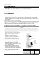
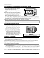
5-9 Microwave Heat Distribution - Heat Evenness
The microwave heat distribution can be checked indirectly by measuring the water temperature rise at
certain positions in the oven:
1. Prepare five beakers made of 'Pyrex', having 100 milliliters capacity each.
2. Measure exactly 100milliliters off water load with a measuring cylinder, and pour into each beaker.
3. Measure the temperature of each water load. (Readings shall be taken to the first place of decimals.)
4. Put each beaker in place on the cooking tray as illustrated in figure below. Start heating.
5. After heating for 2 minutes, measure the water temperature in each beaker.
6. Microwave heat distribution rate can be calculated as follows:
Heat Distribution =
Minimum
Temperature Rise
Maximum
Temperature Rise
D
X 100(%)
Beaker
D
The result should exceed 65%.
D/4
D/4
D/4
D/4
Samsung Electronics
Cooking Tray
5-3
Alignment and Adjustments
5-10 Procedure for Measurement of Microwave Energy Leakage
1) Pour 275¡ 15cc of 20¡ 5¡ ( 68¡ 9¢ ) water in a
beaker which is graduated to 600cc, and place
the beaker in the center of the oven.
2) Start to operate the oven and measure the
leakage by using a microwave energy survey
meter.
3) Set survey meter with dual ranges to 2,450MHz.
4) When measuring the leakage, always use the 2
inch spacer cone with the probe. Hold the probe
perpendicular to the cabinet door. Place the
spacer cone of the probe on the door and/or
cabinet door seam and move along the seam, the
door viewing window and the exhaust openings moving the probe in a clockwise direction at a rate of 1
inch/sec. If the leakage testing of the cabinet door seam is taken near a corner of the door, keep the probe
perpendicular to the areas making sure that the probe end at the base of the cone does not get closer than 2
inches to any metal. If it gets closer than 2 inches, erroneous readings may result.
5) Measured leakage must be less than 4mW/cm2, after repair or adjustment.
Maximum allowable leakage is 5mW/cm2.
4mW/cm2 is used to allow for measurement and meter accuracy
5-11 Check for Microwave Leakage
1. Remove the outer panel.
2. Pour 275±15cc of 20±5ûC(68±9ûF) water in a
beaker which is graduated to 600cc, and
place the beaker in the center of the oven.
3. Start the oven at the highest power level.
4. Set survey meter dual ranges to 2,450MHz.
5. Using the survey meter and spacer cone as
described above, measure arnear the
opening of magnetron, the surface of the air
guide and the surface of the wave guide as
shown in the following photo.( but avoid the
high voltage components.) The neading
should be less than 4mW/cm2.
WARNING
AVOID THE HIGH VOLTAGE COMPONENTS.
5-12. Note on Measurement
1) Do not exceed the limited scale.
2) The test probe must be held on the grip of the handle, otherwise a false reading may result when the
operator's hand is between the handle and the probe.
3) When high leakage is suspected, do not move the probe horizontally along the oven surface; this may
cause damage to the probe.
4) Follow the recommendation of the manufacturer of the microwave energy survey meter.
5-13 Leakage Measuring Procedure
5-13-1 Record keeping and notification after measurement
1) After adjustment and repair of a radiarion preventing device, make a repair record for the measured
values, and keep the data.
2) If the radiation leakage is more than 4 mW/§† after determining that all parts are in good condition,
functioning properly and the identical parts are replaced as listed in this manual notift that fact to ;
5-13-2 At least once a year have the microwave energy survey meter checked for accuracy by its
manufacturer.
5-4
Samsung Electronics
6. Troubleshooting
PRECAUTION
1. CHECK GROUNDING BEFORE CHECKING FOR TROUBLE.
2. BE CAREFUL OF THE HIGH VOLTAGE CIRCUIT.
3. DISCHARGE THE HIGH VOLTAGE CAPACITOR.
4. WHEN CHECKING THE CONTINUITY OF THE SWITCHES OR TRANSFORMER, DISCONNECT ONE LEAD WIRE FROM THESE
PARTS AND THEN CHECK CONTINUITY WITHOUT THE POWER SOURCE ON. TO DO OTHERWISE MAY RESULT IN A FALSE
READING OR DAMAGE TO YOUR METER.
5. DO NOT TOUCH ANY PART OF THE CIRCUIT OR THE CONTROL CIRCUIT BOARD, SINCE STATIC DISCHARGE MAY DAMAGE IT.
ALWAYS TOUCH GROUND WHILE WORKING ON IT TO DISCHARGE ANY STATIC CHARGE BUILT UP.
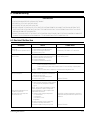
6-1 Electrical Malfunction
SYMPTOM
CAUSE
CORRECTIONS
Oven is dead.
Fuse is OK.
No display and no operation at all.
1. Open or loose lead wire harness
2. Open thermal cutout (Magnetron)
3. Open low voltage transformer
4. Defective Ass'y PCB
Check fan motor when thermal cutout is defective.
No display and no operation at all.
Fuse is blown.
1. Shorted lead wire harness
2. Defective primary latch switch (NOTE 1)
3. Defective monitor switch (NOTE1)
4. Shorted HVCapacitor
5. Shorted HVTransformer (NOTE2)
Check adjustment of primary, interlock monitor,
door sensing switch.
Check Ass'y PCB when LVT is defective.
NOTE 1: All of these switches must be replaced at the same time.
(refer to adjustment instructions)
Check continuity of power relay contacts and if it has continuity, replace power
relay also.
NOTE 2: When HVTransformer is replaced, check diode and magnetron also.
Oven does not accept
key input (Program)
Timer starts countdown but no
microwave oscillation.
(No heat while oven lamp and
fan motor turn on.)
Samsung Electronics
1. Key input is not in-Sequence
2. Open or loose connection of membrane
key pad to Ass'y PCB
3. Shorted or open membrane panel
4. Defective Ass'y PCB
Refer to operation procedure.
1. Off-alignment of latch switches
2. Open or loose connection of high voltage
circuit especially magnetron filament
circuit
NOTE: Large contact resistance will bring
lower magnetron filament voltage and
cause magnetron to lower output and/or
intermittent oscillation.
3. Defective high voltage components
H.V.Transformer
H.V.Capacitor
H.V.Diode,H.V.Fuse
Magnetron
4. Open or loose wiring of power relay
5. Defective primary latch switch
6. Defective power relay or Ass'y PCB
Adjust door and latch switches.
Replace PCB main.
Check high voltage component according to
component test procedure and replace if it is
defective.
Replace PCB main.
6-1
Troubleshooting
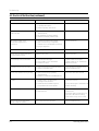
6-1 Electrical Malfunction(continued)
SYMPTOM
CAUSE
CORRECTIONS
Oven lamp and fan motor turn on
1. Misadjustment or loose wiring
of primary latch switch
2. Defective primary latch switch
Adjust door and latch switches.
Oven can program but timer
does not start.
1. Open or loose wiring of secondary
interlock switch
2. Off-alignment of primary interlock
3. Defective secondary interlock S/W
Adjust door and interlock switches.
Microwave output is low;.
Oven takes longer time to
cook food.
1. Decrease in power source voltage.
2. Open or loose wiring of magnetron
filament circuit. (Intermittent oscillation))
3. Aging of magnetron
Consult electrician.
Fan motor turns on when plugged in
Loose wiring of door sensing switch
Check wire of door sensing switch.
Oven does not operate and return
to the plugged in mode.
Defective Ass'y PCB
Replace PCB main.
Loud buzzing noise can be heard.
1. Loose fan and fan motor
2. Loose screws on H.V.Transformer
3. Shorted H.V.Diode
Tighten screws of fan motor.
Tighten screws of H.V.Transformer.
Replace H.V.Diode.
Turntable motor does not rotate.
1. Open or loose wiring of turntable motor.
2. Defective turntable motor.
Check the wire of turntable motor
Replace turntable motor.
Oven stops operation during cooking
1. Open or loose wiring of primary
interlock switch
2. Operation of thermal cutout(Magnetron)
Adjust door and latch switches.
Sparks
1. Metallic ware or cooking dishes
touching on the oven wall.
2. Ceramic ware trimmed with gold or
silver powder also causes sparks.
Inform the customer.
Do not use any type of cookware with
metallic trimming.
Uneven cooking
Uneven intensity of microwave due to
its characteristics.
Wrap thinner parts of the food with
aluminum foil.
Use plastic wrap or cover with a lid.
Stir once or twice while cooking
foods such as soup, cocoa, or milk.
Noise from the turntable motor
when it starts to operate.
Noise may result from the motor.
Replace turntable motor.
6-2
Samsung Electronics
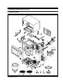
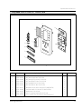
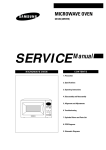
7. Exploded Views and Parts List
7-1 Exploded Views
2
3
1
58
4
57
13 14
6
7
56
55
8
9
15
1011
16
51
17
12
18
23
54
59
19
20
53
71
30
28
27
24
70
5
52
62
50
29
31
21
26
22
33
NC
69
61
34
NO
COM
36
35
37
38
46
60
45
32
44
47
63
39
48
76
40
49
64
42
65
41
43
75
72
73
74
66
67
Samsung Electronics
68
7-1
Exploded Views and Parts List
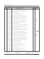
7-2 Main Parts List
Ref. No.
Parts No.
Description/Specification
Q'ty
1
DE70-30029Z
PANEL-OUTER;SECC T0.6 W405.5 L1174.8 SC-WH
1
2
DE63-90035G
CUSHION-RUBBER;DFA20 T2 W190 L100 BLK
1
3
DE61-50073D
BRACKET-UPPER;ALSTAR T0.6 W273 L432 MB6544W
1
4
DE61-70060A
SPRING-PLATE;SK-5 T0.5
1
5
DE47-40029A
SOCKET-LAMP;250V2A 22.230 E14 BJB
1
6
DE61-30185A
SUPPORTER-HEATER;ALUMINA T12 NTR
1
7
DE47-70031B
HEATER-GRILL;D6.8 230V 1400W 37.00HM RE-130
1
8
DE60-40009B
WASHER-TEFLON; SLOT ID22.2 OD28 T1.2 TEFLON
1
9
DE63-20017A
GASKET-HEATER;BRASS T1.5 OD30.5 ID22.5
1
10
DE60-90006A
FLANGE-RING;C3604BD ID22.1 OD26 L4.7 MBGF45
1
11
DE61-50347A
BRACKET-EARTH;BSS2-A T1.0 W35 L43 MBGF45
1
12
DE61-50027B
BRACKET-HEATER;SECC T1.0 W51 L55 CE945GF
1
13
DE61-50076A
BRACKET-AIR GUIDE;ALCOAT T0.8 W61 L218.5
1
14
DE65-20014A
CABLE-CLAMP;DA6-N NY 66
1
15
DE39-20058B
ASSY POWER CORD;KKP-4819D/B232 1.5MM 250V16
1
16
DE71-60386A
COVER-BACK;SCP3 T0.6 W275 L385.5 BLK-COATING
1
17
DE91-40042A
ASSY NOISE FILTER;DNA-1019(C)250V 10A CMO-
1
18
DE61-30129A
SUPPORT-P.C.B;DASS-T9N
2
19
DE31-10080B
MOTOR-FAN;AMM92-002AUEE(NEW) 230V MIN2550RP
1
20
DE39-40606A
ASSY WIRE HARNESS-A;230V50HZ CE105K/CE115K
1
21
4713-000168
LAMP-INCANDESCENT;230V,-,25W,ORG,-,-,
1
22
DE65-20025A
CABLE CLAMP;DAWS-2NB NYLON66 NTR WIRE SADDL
1
23
DE63-90065E
CUSHION-LAMP;PUT-FOAM T40 W10 L90 M6245
1
24
DE01-00051A
FILM-LAMP;T0.25 W105 L85 CLEAR RE-1300
1
26
DE62-90046A
ADIABATIC-RIGHT;T3 W219.3 L214.8 RE-1300
1
27
DE71-60294A
COVER-ADIABATIC;SECC T0.6 W249.7 L353.5 RE-1300
1
28
DE61-30132A
SUPPORTER-MGT;SECC T0.6 W38 L342.5 MW6630T
1
29
DE47-20005A
THERMOSTAT;PW-2N(130/60) 187Y30 250V7.5A 130
1
30
DE47-20003A
THERMOSTAT;NT-101NA(8*V)P 160-60 250V7.5A 16
1
31
DE03-30035A
MAGNETRON;OM75PH(31)ESS
1
32
DE92-90213A
ASSY COVER-AIR; RE-1300
1
33
DE93-20020A
ASSY BODY LATCH;RE-43B/90B
1
34
DE66-40001A
LATCH-BODY;POM 50G M8135G NEW LATCH
1
35
3405-000178
SW-MICRO;VP-533A-OF-PS(T85) 250V,15A,20
2
36
DE72-60106A
GUIDE-S/W;ABS BLK
1
37
3405-000175
SW-MICRO;VP-531-OF (T85) 250V,15A,200GF
1
38
DE66-90001A
LEVER-SWITCH;POM(F20) 2 6 NTR 2ND-W
1
39
DE59-40001A
DIODE-H.V;HVR-1X-32B-12
1
40
DE91-70061A
ASSY-H.V.FUSE;THV060T-0800-H 5KV/0.8A RED
1
: Option Parts
7-2
: Warning
Remarks
:Electrostatically Sensitive Devices
Samsung Electronics
Exploded Views and Parts List
7-2 Main Parts List
Ref. No.
Parts No.
41
42
43
44
45
46
47
48
49
50
51
52
53
54
55
56
57
58
59
60
61
62
63
64
65
66
67
68
69
70
71
72
73
74
75
76
DE26-20152A
DE61-40026A
DE60-60025A
DE61-50106A
2501-001030
DE26-10100D
DE63-90065J
DE80-10031B
DE65-20025A
DE31-10170A
DE47-20109A
DE71-60313A
DE61-80006B
DE61-80037C
DE32-10013A
DE72-60035Q
DE39-40637A
DE39-30147C
DE65-20012A
DE63-90062A
DE74-20025C
DE74-20016A
DE92-90189C
DE67-60028A
DE92-90211A
DE92-90211B
DE73-90027A
DE61-50490A
DE91-70101B
DE74-40001A
DE67-60074A
DE72-80062A
DE74-20022A
DE74-20105B
Samsung Electronics
Description/Specification
TRANS-L.V;SLV-105E 230V 50HZ AC17V/3V
FOOT;P.P JI350 BLK
PIN-FOOT;P.P-JI350BLK
BRACKET-H.V.C;SECC T0.8 W31 L125.8
C-OIL;1.1uF,2100V,BK,35x54x95,20mm
TRANS-H.V;SHV-945EG1-2 230V50HZ 2300V/DPC
CUSHION-GUIDE;PUT FOAM T40 W10 L460 MX246
BASE-PLATE;SGCC1-Z T0.8 W375 L588 RE-1300
CABLE-CLAMP;DAWS-2NB NYLON66 NTR WIRE SADDL
MOTOR-DRIVE;M2LJ24Z702 ST-16F 220/240V 2.5/
THERMOSTAT;NT-101NA(5XH)P 125V15A H 130/60
COVER-CEILING;MICA SHEET T0.5 W48.5 L117 RE-1300
HINGE-LOWER;ZP2W T3.0 ZN(PLATING) RE-552
HINGE-UPPER;SCP1 T3.0 W26 L76 ZP2C-W MB245
SENSOR-THERMISTOR;PT-312-K2
GUIDE-AIR;SECC (T)0.6 (W)240 (L)242 5 RE-13
ASSY WIRE HARNESS-B;230V50HZ CE115K
WIRE LEAD-E;120*180 GRN,GRN RE-1300
CORD-CLAMP;DALC-2-1 SILICON
ASSY CONTROL-BOX
ASSY DOOR
CUSHON-RUBBER DOOR;RUBBER(CR) T9 W30 L50
TRAY-CONVECTION;SPP T0.8 W12 L325.9 CE104CF
TRAY-COOKING;GLASS T5.0 PI345 1250G M551T
ASSY-GUIDE ROLLER;D22.5 RE-1300
COUPLER;PTFE 20G WHT RE-1300
ASSY-WIRE RACK(HIGH);RE-1300 H104 PI3
ASSY-WIRE RACK(LOW);RE-1300 H44 PI3
FERRITE-CORE;NI-ZN T13.8 W21.0 L28.0 BNF-14
BRACKET-TCO;SECC1 T0.6 34 58
ASSY THERMOSTAT;RE-542 160/60 187 TYPE
SPIT-BARBECUE;MSWR CE945G SNC2
COUPLER-BARBECUE;PTFE 29G WHT CE104CF
SHAFT-BARBECUE;STS304 D3 L149 W60.25 CE97
TRAY-OIL;GLASS(NEOREX) T5 PI210 600G
TRAY-CRUSTY;T5 P1300 H30 830G TEFLON-COAT
Q'ty
Remarks
1
4
4
1
1
1
1
1
1
1
2
1
1
1
1
1
1
1
1
1
1
1
1
1
1
1
1
1
1
1
1
1
1
1
1
1
7-3
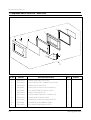
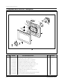
Exploded Views and Parts List
7-3 Exploded View & Parts List - Door Parts
7
6
5
1
2
4
3
10
8
9
11
Ref. No.
Parts No.
1
DE64-20117A
HANDLE-DOOR;PC WHT 30G CE115K
1
2
DE02-00082A
TAPE-DOUBLE FACE;PET T0.4 W9 WHT SEIL SI-500HI
1
3
DE64-40279A
DOOR-A;PC WHT 300G CE115K
1
4
D64-40286A
DOOR-SUB;PC T2.0 W267.6 L402.6 100G BLK CE1
1
5
DE92-50080E
ASSY DOOR-E;MBG45 COATING SIL/SELANT
1
6
DE64-40173A
DOOR-C;PBT BLK 24G RE-1300
1
7
DE67-20163A
SCREEN-DOOR(B);TEMP GLASS T3.2 W261.6 L397
1
8
DE64-40175A
DOOR-KEY;POM(TC3005) BLK 13G RE-
1
9
DE61-70041B
SPRING-KEY;ES HSW3 PI0.7 D4.9 BLUING RE-751
1
10
DE60-60008F
PIN-HINGE;PI4 L15 NYLON#66 CE115K BLK
2
11
DE92-40185A
ASSY DOOR;CE115K(SAW) WHT VITALITY
1
7-4
Description/Specification
Q'ty
Remarks
Samsung Electronics
Exploded Views and Parts List
7-4 Exploded View & Parts List - Control Parts
8
10
7
1
3
2
9
4
5
6
11
Ref. No.
Parts No.
1
2
3
4
5
6
7
8
9
10
11
DE66-20192A
DE66-20195A
DE66-20196A
DE66-20194A
DE66-20191A
DE66-20193A
DE67-40150F
DE72-70185N
DE64-10132A
DE91-10438A
DE93-30419N
Samsung Electronics
Description/Specification
BUTTON-SELECT-A;PC WHT 20G CE115K
BUTTON-CLOCK;PC WHT 5G CE115K
BUTTON-SELECT-B;PC WHT 15G CE115K
BUTTON-DEFROST;PC WHT 20G CE115K
BUTTON-MORE;PC WHT 13G CE115K
BUTTON-CANEL;PC WHT 20G CE115K
WINDOW-DISPLAY;ACRYL SMG 30G CE118KFR(SBTW)
CONTROL-PANEL;PC 230G WHT CE118KFR (SBTW)
KNOB;PC WHT 10G CE115K
ASSY P.C.B-MAIN;230V50HZ S VFD CE115K
ASSY CONTROL-BOX;230V50HZ CE118KFR(SBTW) WHT
Q'ty
Remarks
1
1
1
1
1
1
1
1
1
1
1
7-5
Exploded Views and Parts List
7-5 Exploded View & Parts List - Casing Parts
12
9
10
11
7
6
8
2
5
1
3
4
13
Ref. No.
Parts No.
1
2
3
4
5
6
7
8
9
10
11
12
13
DE60-30016B
DE31-90020A
DE60-40026B
DE72-30016B
DE62-90098A
DE61-50484A
DE47-70077A
DE92-90487A
DE62-10014A
DE47-20029A
DE31-90019A
DE31-10171A
DE92-90478A
7-6
Description/Specification
NUT-FLANGE;M4 MSWR10 FEFN
BLADE-FAN;ALSTAR T0.6 W250 L250
WASHER-PLAIN;ID5.5 OD12 T1.0 SBC1ZNC3
BUSH-MOTOR;MSWR3 D5.6 L15.7 CE115K
ADIABATIC-CASING;T5 W245 L336.8 CE115K
BRACKET-HEATER;STS430 T0.8 W27.2 L26 CE115K
HEATER-CONVECTION;230V 1680W 30.7 7.0
ASSY-COVER CASING;CE115K 230V50HZ
INSULATION-TCO;T2.0 W34 L26 YEL
THERMOSTAT;PW-2N(160/60,Y,23.8) 250V/7.5A
BLADE-FAN;SECC T0.6
MOTOR-CONVECTION;SMC-105EA 230V/50HZ 2800RP
ASSY-CASING;CE115K/CE105K 230V50HZ
Q'ty
1
1
1
1
1
1
1
1
1
1
1
1
1
Remarks
¡
¡
¡
¡
¡
¡
Samsung Electronics
Exploded Views and Parts List
7-6 Parts List - Standard Parts
Parts No.
DE60-10098A
DE60-10098A
DE60-10082H
DE60-10082H
DE60-20014A
DE60-10046A
DE60-10052A
DE60-10080A
DE60-10082H
DE60-10012A
DE60-10013A
DE60-10018A
DE60-10012A
DE60-10082H
DE60-10082H
DE60-10088A
DE60-10034A
DE60-10082H
DE60-10082H
DE60-10122A
DE60-10122A
DE60-10080A
DE60-10082H
DE60-10082H
DE60-10082H
DE60-10082H
DE60-10082H
DE60-10082H
DE60-10082H
DE60-10082H
DE60-10098A
DE60-10082H
DE60-30016B
DE60-10013A
DE60-10082H
Description/Specification
SCREW-ASSY TAPTITE;PH TC M4X8 SWRCH18A Z
SCREW-ASSY TAPTITE;PH TC M4X8 SWRCH18A Z
SCREW-A;2S-4X12(TOOTHED)
SCREW-A;2S-4X12(TOOTHED)
BOLT-FLANGE;M5 L10 MSWR3 FEFZY
SCREW-TAP PH;PH M3 L8 FEFZY
SCREW-TAP PH;PH M4 L8 FEFZY
SCREW-WASHER;M5 L12 2S
SCREW-A;2S-4X12(TOOTHED)
SCREW-TAP TITE;TH + 3 M4 L10 SWR10 ZPC2
SCREW-ASSY TAP;TH 2S 4 L12 MSWR3 ZPC3 FI
SCREW-ASSY MACHINE;PH M4X0.7P 8 MSWR10 S
SCREW-TAP TITE;TH + 3 M4 L10 SWR10 ZPC2
SCREW-A;2S-4X12(TOOTHED)
SCREW-A;2S-4X12(TOOTHED)
SCREW-TAP PH;PH M3 L8 FEFZY PLAIN
SCREW-TH;TH + M4 L10 STS304
SCREW-A;2S-4X12(TOOTHED)
SCREW-A;2S-4X12(TOOTHED)
SCREW-TAP TH;TAP TH 2-4X8 FE FN
SCREW-TAP TH;TAP TH 2-4X8 FE FN
SCREW-WASHER;M5 L12 2S
SCREW-A;2S-4X12(TOOTHED)
SCREW-A;2S-4X12(TOOTHED)
SCREW-A;2S-4X12(TOOTHED)
SCREW-A;2S-4X12(TOOTHED)
SCREW-A;2S-4X12(TOOTHED)
SCREW-A;2S-4X12(TOOTHED)
SCREW-A;2S-4X12(TOOTHED)
SCREW-A;2S-4X12(TOOTHED)
SCREW-ASSY TAPTITE;PH TC M4X8 SWRCH18A Z
SCREW-A;2S-4X12(TOOTHED)
NUT-FLANGE;M4 MSWR10 FEFN
SCREW-ASSY TAP;TH 2S 4 L12 MSWR3 ZPC3 FI
SCREW-A;2S-4X12(TOOTHED)
Samsung Electronics
Q'ty
2
2
1
2
4
2
1
4
9
3
4
2
1
1
2
5
1
2
1
2
2
4
2
1
1
2
5
4
2
1
4
1
1
1
2
Remarks
CV-TCO
M/DRIV
CV/AIR
SW-THE
HINGE
MGTCO
B/HING
HVT
BASEGROUP
CV-MOT
B/EART
HVD
B/C-MO
LVT
PCB
SENSOR
CV-BAK
BKT/U
B/HEAT
C-CEIL
MGT
CN-BOX
CV/AIR
SU/MGT
SW-THE
PN-OUT
A/CSIG
B/LATH
B/WAVE
AS-CSI
B/AI-G
SENSOR
CB-CMP
GU-AIR
7-7
8. P.C.B Diagrams
8-1 P.C.B Diagrams
8-1
Samsung Electronics
P.C.B Diagrams
8-2 P.C.B Parts List
Parts No.
0401-001002
0402-000559
0403-000387
0501-000283
0501-000388
0504-001014
0504-001015
2001-000037
2001-000273
2001-000290
2001-000429
2001-000435
2001-000613
2001-000780
2011-001072
2202-000780
2202-000796
2401-000247
2401-000914
2401-001412
2802-000143
3501-001014
3501-001015
3501-001016
3501-001016
3708-000528
3711-000203
3711-000240
3711-000881
71607-402-290
A1100-1049
A4106-0154
DE07-10081A
DE09-30509A
DE13-20009A
DE26-20141A
DE30-20016A
DE39-60001A
DE41-10361A
DE60-60012A
DE61-90004A
Samsung Electronics
Description / Specification
DIODE-SWITCHING;1N4148M,100V,200mA,500mW
DIODE-RECTIFIER;D4G,400V,1A,T-1
DIODE-ZENER;UZP24B,24V,22.8-25.6V,1W,DOTR-SMALL SIGNAL;KSA539-Y,PNP,400mW,TO-92
TR-SMALL SIGNAL;KSC815-Y,NPN,400mW,TO-92
TR-DIGITAL;KSR1005,NPN,300mW,4.7K-10K,TO
TR-DIGITAL;KSR2005,PNP,300mW,4.7K-10K,TO
R-CARBON(S);330ohm,5%,1/2W,AA,TP,2.4x6.4
R-CARBON;100Kohm,5%,1/8W,AA,TP,1.8x3.2m
R-CARBON;10Kohm,5%,1/8W,AA,TP,1.8x3.2mm
R-CARBON;1Kohm,5%,1/8W,AA,TP,1.8x3.2mm
R-CARBON;1Mohm,5%,1/8W,AA,TP,1.8x3.2mm
R-CARBON;3.9Kohm,5%,1/8W,AA,TP,1.8x3.2m
R-CARBON;470ohm,5%,1/8W,AA,TP,1.8x3.2mm
R-NETWORK;47Kohm,5%,1/8W,A,SIP,6P,TP
C-CERAMIC,MLC-AXIAL;UP050F104Z 100NF,+80
C-CERAMIC,MLC-AXIAL;UP050B102KB 1NF,10%,
C-AL;1SA1ANB107MAN 100UF,20%,10V,GP 6.3X
C-AL;CESSL1C220M0511AA 22UF,20%,16V,GP 5
C-AL;1SG1VFB477MAN 470UF,20%,35V,GP 10X1
RESONATOR-CERAMIC;KBR-4.19M 4.19MHZ,0.5%
RELAY-POWER;OM1F-S-124LM 24V,21.8MA,17A
RELAY-POWER;OZF-S-124LM1P 24V,21.8MA,16A
RELAY-MINIATURE;JV24-KT 24V,12.5MA,5A 1F
RELAY-MINIATURE;JV24-KT 24V,12.5MA,5A 1F
CONNECTOR-FPC/FC/PIC;FCZ254-13SL,BLK 13P
CONNECTOR-HEADER;YW396-03AV WHT STRAIGHT
CONNECTOR-HEADER;1WALL,4P,1R,3.96mm,STRA
CONNECTOR-HEADER;SMW250-03,WHT BOX,3P,1R
C-ELEC;04W 50V 100UF (TAPG)
C-CERAMIC;CC OA CH 50V T 220-J 3.5X1.9 U
DIODE-ZENER;TZP5.1B 5.1/5.7V 40MA T 1W
V.F.DISPLAY;SVM-4SM03 GRN/RSHORG 4 51 81
IC-MCU;HD404316-C16S DIP CE945G/CE745G(E
IC;KA7533 DIP
TRANS-L.V;SLV-945E 230V 50HZ AC17/2.9V
BUZZER;CBE2220BA STICK
WIRE-SO COPPER;PI0.6 SN T 52MM TAPING_WI
P.C.B-MAIN;FR-1 T1.6 W88 L163 EU2(M945)
PIN-EYELET;ID2.1 OD2.5 L3.0 SN BSP T0.25
HOLDER-DIGITRON;NYLON#66 1.5 85 36 8GR B
Q'ty
Remarks
16
3
1
1
1
6
1
2
1
6
8
1
7
2
1
5
4
1
1
1
1
1
1
1
1
1
1
1
1
1
2
3
1
1
1
1
1
25
1
8
1
D4~19
D1~3
ZD04
TR01
TR03
TR2,4~8
TR09
R1,2
R16
R12~14,19~21
R5,6,8~10,18,22,23
R07
R11,15,17,24~27
R3,4
AR01
C5,6,9,10,19
C11~14
C03
C04
C01
XTL1
RY01
RY04
RY02
RY03
CN04
CN01
CN02
CN03
C02
C7,8
ZD1~3
VFD1
IC01
IC02
LVT1
BUZ1
J1~25
E1~8
8-2
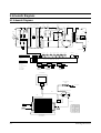
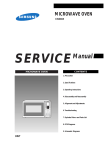
9. Schematic Diagrams
9-1 Schematic Diagrams
ASSY CHOCK P.C.B
CAVITY
T.C.O
MGT
T.C.O
PRIMARY
SWITCH
BRN
N
YEL
WHT
H.V.T
WHT
YEL
0V
BLU
H.V.D
COM
CM
NO
L.V.T
ORG
CONV MOTOR
FAN MOTOR
FM
RED
H.V.C
MONITER
SWITCH
NC
CONV
MOTOR
RELAY
500K
E
DM
ORG
FAN
MOTOR
RELAY
DRIVE MONITER
LAMP
2200pF
1mH
L
H.V.FUSE
(0.8A)
RED
RED
PNK
BLU
MONITER
FUSE (1.6A)
GRILL
RELAY
BLU
FUSE 10A
Thermistor
Sensor
ORG
WHT
2200pF
F
WHT
RED
YEL
LIN-CAPACITORT 0.1uF
ORG
RED
BRN
WHT
BRN
CONV
RELAY
V/G
GRILL
HEATER
ORG
CONV
T.C.O
GRILL
T.C.O
230V~
50Hz
YEL
CONV
HEATER
BRN
L
BRN
BRN
BLU
INRUSH
RELAY
MAIN
RELAY
RED
RESISTOR
ORG
RED
F
RED
FA
BLU
BLU
BLU
BLU
POWER
RELAY
MAGNETRON
Power Conv Motor Fan Motor
Relay
Relay
Relay
Inrush
Relay
Conv Heater
Relay
Door Sensing
Switch
KEY BOARD
ORG
CONDITION OF OVEN
Main
Relay
DOOR IS OPENED
COOK OFF
GRN
ORG
Grill Heater
Relay
Thermistor
Sensor
A S S Y M A I N P.C.B
WIRING COLOR
BRN : BROWN
WHT : WHITE
RED : RED
Y/G : YELLOW/GREEN
BLU : BLUE
ORG : ORANGE
YEL : YELLOW
PNK : PINK
COM NO
BRN RED
BRN
COM NO
ORG
NC
COM NO
ORG
PRIMARY LATCH
SWITCH
BRN
RED BLU
BRN
MONITOR
SWITCH
DOOR SENSING
SWITCH
MAGNETRON
HIGH VOLTAGE
DIODE
TO CHASSIS
FA
F
HIGH VOLTAGE CAPACITOR
ORG
RED
RED
H.V.FUSE
BRN
RED
BLU
SYMBOL COLOR
ORG
ORANGE
BRN
BROWN
BLK
BLACK
RED
RED
BLU
BLUE
HIGH VOLTAGE
TRANSFORMER
9-1
Samsung Electronics