1
MICROWAVE OVEN
CK95 / CK96T / CK97B / CK98F
SERVICE
Manual
CONTENTS
MICROWAVE OVEN
1. Precaution
2. Specifications
3. Operating Instructions
4. Disassembly and Reassembly
5. Alignment and Adjustments
GB/F/D/E/I/NL/R
Auto
Auto
/
6. Troubleshooting
Auto
/C
1min+
7. Exploded Views and Parts List
8. PCB Diagrams
9. Schematic Diagrams
1. Precaution
Follow these special safety precautions. Although the microwave oven is completely safe during ordinary
use, repair work can be extremely hazardous due to possible exposure to microwave radiation, as well as
potentially lethal high voltages and currents.
1-1 Safety precautions (
)
1. All repairs should be done in accordance
with the procedures described in this
manual. This product complies with
Federal Performance Standard 21 CFR
Subchapter J (DHHS).
2. Microwave emission check should be
performed to prior to servicing if the oven is
operative.
3. If the oven operates with the door open :
Instruct the user not to operate the oven and
contact the manufacturer and the center for
devices and radiological health immediatly.
4. Notify the Central Service Center if the
microwave leakage exceeds 5 mW/cm2
5. Check all grounds.
6. Do not power the MWO from a "2-prong"
AC cord. Be sure that all of the built-in
protective devices are replaced. Restore any
missing protective shields.
7. When reinstalling the chassis and its
assemblies, be sure to restore all protective
devices, including: nonmetallic control
knobs and compartment covers.
8. Make sure that there are no cabinet openings
through which people--particularly
children--might insert objects and contact
dangerous voltages. Examples: Lamp hole,
ventilation slots.
9. Inform the manufacturer of any oven found
to have emmission in excess of 5 mW/cm2,
Make repairs to bring the unit into
compliance at no cost to owner and try to
determine cause.
Instruct owner not to use oven until it has
been brought into compliance.
11. To avoid any possible radiation hazard,
replace parts in accordance with the wiring
diagram. Also, use only the exact
replacements for the following parts:
Primary and secondary interlock switches,
interlock monitor switch.
12. If the fuse is blown by the Interlock Monitor
Switch: Replace all of the following at the
same time: Primary and secondary switches,
as well as the Interlock Monitor Switch. The
correct adjustment of these switches is
described elsewhere in this manual. Make
sure that the fuse has the correct rating for
the particular model being repaired.
13. Design Alteration Warning:
Use exact replacement parts only, i.e.,
only those that are specified in the
drawings and parts lists of this manual.
This is especially important for the
Interlock switches, described above.
Never alter or add to the mechanical or
electrical design of the MWO. Any design
changes or additions will void the
manufacturer's warranty.10.Always unplug
the unit's AC power cord from the AC
power source before attempting to
remove or reinstall any component or
assembly.
14. Never defeat any of the B+ voltage
interlocks. Do not apply AC power to the
unit (or any of its assemblies) unless all
solid-state heat sinks are correctly installed.
15. Some semiconductor ("solid state") devices
are easily damaged by static electricity. Such
components are called Electrostatically
Sensitive Devices (ESDs). Examples include
integrated circuits and field-effect
transistors.
Immediately before handling any
semiconductor components or assemblies,
drain the electrostatic charge from your
body by touching a known earth ground.
CENTRAL SERVICE CENTER
10. Service technicians should remove their
watches while repairing an MWO.
Samsung Electronics
16. Always connect a test instrument's ground
lead to the instrument chassis ground before
connecting the positive lead; always remove
the instrument's ground lead last.
1-1
Pretaution
1-2 Special Servicing Precautions (Continued)
17. When checking the continuity of the
switches or transformer, always make sure
that the power is OFF, and one of the lead
wires is disconnected.
18. Components that are critical for safety are
indicated in the circuit diagram by
shading,
or
.
19. Use replacement components that have the
same ratings, especially for flame resistance
and dielectric strength specifications. A
replacement part that does not have the
same safety characteristics as the original
might create shock, fire or other hazards.
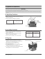
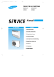
1-3 Special High Voltage Precautions
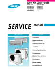
1. High Voltage Warning
Do not attempt to measureany of the high
voltages--this includes the filament voltage
of the magnetron. High voltage is present
during any cook cycle.
Before touching any components or wiring,
always unplug the oven and discharge the
high voltage capacitor (See Figure 1-1)
2. The high-voltage capacitor remains charged
about 30 seconds after disconnection. Short
the negative terminal of the high-voltage
capacitor to the oven chassis. (Use a
screwdriver.)
3. High voltage is maintained within specified
limits by close-tolerance, safety-related
components and adjustments. If the high
voltage exceeds the specified limits, check
each of the special components.
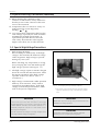
Fig. 1-1. Discharging the High Voltage Capacitor
• : Touch chassis side first then short to the high voltage
capacitor terminal by using a screwdriver or jumper
wire.
PRECAUTION
PRECAUTION
There exists HIGH VOLTAGE ELECTRICITY with high
current capabilities in the circuits of the HIGH VOLTAGE
TRANSFORMER secondary and filament terminals. It is
extremely dangerous to work on or near these circuits
with the oven energized.
DO NOT measure the voltage in the high voltage circuit
including filament voltage of magnetron.
Never touch any circuit wiring with your hand nor with an
insulated tool during operation.
1-2
PRECAUTION
Servicemen should remove their watches whenever
working close to or replacing the magnetron.
Samsung Electronics
2. Specifications
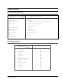
2-1 Table of Specifications
MODEL
ITEM
CK95 / CK96T / CK97B / CK98F
TIMER
99 MINUTES
POWER SOURCE
230V/50HZ, AC
POWER CONSUMPTION
MICROWAVE : 1,500W,GRILL : 1,300W, CONVECTION : 1700W
OUTPUT POWER
FROM100 TO 900W (6 LEVEL POWER)
(IEC-705 TEST PROCEDURE)
OPERATING FREQUENCY
2,450MHz
MAGNETRON
OM75PH(31)
COOLING METHOD
COOLING FAN MOTOR
OUTSIDE DIMENSIONS
517(W) x 310(H) x 511(D)
NET WEIGHT
24.5 Kg
SHIPPING WEIGHT
27.5 Kg
2-2 Comparison Chart
MODEL
FEATURE
MORE/LESS
AUTO REHEAT
AUTO DEFROST
TIME COOK
POWER LEVEL
CONVECTION
GRILL
MICROWAVE + CONVECTION
MICROWAVE + GRILL
PREHEAT
MULTE - LANGUAGE
CLOCK
HOLD / DELAY
CHILD LOCK
SOUND ON / OFF
Samsung Electronics
CK95 / CK96T / CK97B / CK98F
O
O
O
O
O
O
O
O
O
O
O
O
O
O
O
2-1
3. Operating Instructions
3-1 Control Panel
Display
Language Mode Selection
GB/F/D/E/I/NL/R
Auto
Auto
Auto Defrost Feature Selection
Auto Reheat & Cook Feature Selection
/
Cooking Time Adjustment
Standing Time Setting
Clock Setting
Time Setting Weight
Selection and Recipe Selection
Combined Mode Selection (Microwave + Grill)
Microwave / Power Level Mode Selection
Grill Mode Selection
/C
Auto
Preheat Mode Selection
Convection Mode / Temperature Selection
Combined Mode Selection (Microwave + Convection)
Stop / Cancel Button
Start / Cooking Time Adjustment Button
1min+
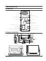
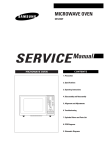
3-2 Features & External Views
Door
Ventilation Holes
Light
Safety Interlock Holes
GB/F/D/E/I/NL/R
Auto
Auto
/
Control Panel
Auto
/C
1min+
Guide Roller
Glass Plate
Door Latches
Coupler
Grill Rack
GB/F/D/E/I/NL/R
Auto
310mm
Auto
/
Auto
/C
1min+
216mm
369mm
517mm
Samsung Electronics
511mm
3-1
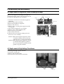
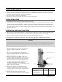
4. Disassembly and Reassembly
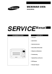
4-1 Replacement of Magnetron, Motor Assembly and Lamp
Remove the magnetron including the shield case,
permanent magnet, choke coils and capacitors (all
of which are contained in one assembly).
Cover Air
Thermo S/W
Lamp
1. Disconnect all lead wires from the magnetron
and lamp.
2. Remove the bracket mounting.
3.Remove the magnetron supporter
4. Remove the air cover.
5. Remove screws securing the magnetron to the
wave guide.
6. Take out the magnetron very carefully.
7. Remove screws from the back panel.
8.Remove the assy noise filter.
9. Take out the fan motor.
10. Remove the oven lamp by pulling out from
hole of air cover carefully.
Fan Motor
Magnetron
NOTE1: When removing the magnetron, make
sure that its antenna does not hit any
adjacent parts, or it may be damaged.
NOTE2: When replacing the magnetron, be sure
to remount the magnetron gasket in
the correct position and make sure the
gasket is in good condition.
H. V. Trans
Screw
H. V. Capacitor
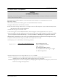
4-2 Replacement of High Voltage Transformer
1. Discharge the high voltage capacitor.
2. Disconnect all the leads.
3. Remove the mounting bolts.
4. Reconnect the leads correctly and firmly.
Bolts
Samsung Electronics
H. V. Trans
4-1
Disassembly and Reassembly
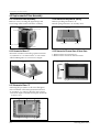
4-3 Replacement of Door Assembly
4-3-1 Removal of Door Assembly
4-3-4 Removal of Key Door & Spring
Remove screws securing the upper hinge and
lower hinge. Then remove the door assembly.
Remove pin hinge from Door "E"
Detach spring from Door "E" and key door.
Door "E"
Upper Hinge
Screws
Key Door
Lower Hinge
Spring
Screws
4-3-2 Removal of Door "C"
4-3-5 Removal of Screen-Door & Deco-Door
Insert flat screwdriver into the gap between Door
"A" and Door "C" to remove Door "C". Be careful
when handling Door "C" because it is fragile.
1. Remove Door"E" from Door"A".
2. Remove Door-Screen"B" and Deco Door.
Deco-Door
Door "C"
Door "A"
4-3-3 Removal of Door "E"
Following the procedure as shown in the figure,
insert and bend a thin metal plate between Door
"E" and Door "A" until you hear the 'tick' sound.
1. Insertion depth of the thin metal plate should be
0.5mm or less.
Door "E"
4-2
Samsung Electronics
Disassembly and Reassembly
4-3-6 Reassembly Test
After replacement of the defective component parts of the door, reassemble it and follow the instructions below for proper
installation and adjustment so as to prevent an excessive microwave leakage.
1. When mounting the door to the oven, be sure to adjust the door parallel to the bottom line of the oven face
plate by moving the upper hinge and lower hinge in the direction necessary for proper alignment.
2. Adjust so that the door has no play between the inner door surface and oven front surface. If the door
assembly is not mounted properly, microwave energy may leak from the space between the door and
oven.
3. Do the microwave leakage test.
4-4 Replacement of Fuse
1. Disconnect the oven from the power source.
2. Remove the 10A fuse in the Noise filter.
3. When replacing the 10A fuse, be sure to use an
exact replacement part. If new 10A fuse blows
out again after replacement, check the primary
interlock switch, door sensing switch and
interlock monitor switch.
4. When the above three switches operate properly,
check if any other part such as the control circuit
board, blower motor or high voltage
transformer is defective.
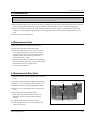
4-5 Replacement of Drive Motor
1. Take out the glass tray and guide roller from the
cavity.
2. Turn the oven upside down to replace the drive motor.
3. Remove a screw securing the drive motor cover.
Drive Motor
Screw
4. Disconnect all the lead wires from the drive motor.
5. Remove screws securing the drive motor to the
cavity.
6. Remove the drive motor and coupler.
7. When replacing the drive motor, be sure to
remount it in the correct position with the
coupler.
8. Connect all the leads to the drive motor.
Drive Motor Cover
Base Plate
9. Screw the drive motor cover to the base plate
with a screw driver.
Samsung Electronics
4-3
Disassembly and Reassembly
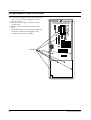
4-6 Replacement of Control Circuit Board
1. Be sure to disclyarge any static electricity from
your body, and avoid touching the "Touch
control" clrcuitry.
2. Disconnect the connectors from the control
circuit board.
3. Remove screws securing the control circuit
bord.
4. Lift up the control circuit board from right side
and remove the hooks holding the contol
circuit board to the box assembly.
SCREWS
4-4
Samsung Electronics
5. Alignment and Adjustments
PRECAUTION
1. High voltage is present at the high voltage terminals during any cook cycle.
2. It is neither necessary nor advisable to attempt measurement of the high voltage.
3. Before touching any oven components or wiring, always unplug the oven from its power source and discharge the high voltage
capacitor.
5-1 High Voltage Transformer
1. Remove connectors from the transformer terminals
and check continuity.
2. Normal resistance readings are as follows:
Secondary
Filament
Primary
Filament Terminals
90.0Ω ± 10%
Shows Continuity
1.45Ω ± 10%
(Room temperature = 20ûC)
Primary
Terminals
5-2 Low Voltage Transformer
1. The low voltage transformer is located on the
control circuit board.
2. Remove the low voltage transformer from the
PCB Ass'y and check continuity.
3. Normal resistor reading is shown in the table.
Terminals
Resistance
1~2(Input)
3~4(Output)
5~6(Output)
290Ω
4.0Ω
1.0Ω
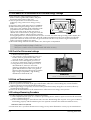
5-3 Magnetron
1. Continuity checks can indicate only an open
filament or a shorted magnetron. To diagnose an
open filament or shorted magnetron :
2. Isolate the magnetron from the circuit by
disconnecting its leads.
3. A continuity check across the magnetron filament
terminals should indicate one ohm or less.
4. A continuity check between each filament terminal
and magnetron case should read open.
Magnetron Antenna
Gasket Plate
Cooling Fins
Samsung Electronics
5-1
Alignment and Adjustments
5-4 High Voltage Capacitor
1. Check continuity of the capacitor with the meter set at the highest resistance scale.
2. Once the capacitor is charged, a normal capacitor shows continuity for a short time, and then indicates 9MΩ.
3. A shorted capacitor will show continuous continuity.
4. An open capacitor will show constant 9MΩ.
5. Resistance between each terminal and chassis should read infinite.
5-5 High Voltage Diode
1. Isolate the diode from the circuit by disconnecting its leads.
2. With the ohm-meter set at the highest resistance scale, measure across the diode terminals. Reverse the
meter leads and read the resistance. A meter with 6V, 9V or higher voltage batteries should be used to
check the front-to back resistance of the diode (otherwise an infinite resistance may be read in both
directions). The resistance of a normal diode will be infinite in one direction and several hundred KΩ in
the other direction.
5-6 Main Relay and Power Control Relay
1. The relays are located on the PCB Ass'y. Isolate them from the main circuit by disconnecting the leads.
2. Operate the microwave oven with a water load in the oven. Set the power level set to high.
3. Check continuity between terminals of the relays after the start pad is pressed.
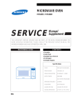
5-7 Adjustment of Primary Switch, Door Sensing Switch and Monitor Switch
Precaution
For continued protection against radiation hazard, replace parts in accordance with the wiring diagram and be sure to use the
correct part number for the following switches: Primary and door sensing switches, and the interlock monitor switch (replace all
together). Then follow the adjustment procedures below. After repair and adjustment, be sure to check the continuity of all
interlock switches and the interlock monitor switch.
1. When mounting Primary switch and Interlock
Monitor switch to Latch Body, consult the
figure.
Primary Interlock Switch
2. No specific adjustment during installation of
Primary switch and Monitor switch to the latch
body is necessary.
3. When mounting the Latch Body to the oven
assembly, adjust the Latch Body by moving it so
that the oven door will not have any play in it.
Check for play in the door by pulling the door
assembly. Make sure that the latch keys move
smoothly after adjustment is completed.
Completely tighten the screws holding the Latch
Body to the oven assembly.
4. Reconnect to Monitor switch and check the
continuity of the monitor circuit and all latch
switches again by following the components test
procedures.
5. Confirm that the gap between the switch
housing and the switch actuator is no more than
0.5mm when door is closed.
5-2
Interlock Monitor
Switch
Lever Switch
Body Latch
Primary switch
Monitor switch (COM-NC)
Door Sensing S/W
Door Sensing
Switch
Door Open
Door Closed
∞
0
∞
0
∞
0
Samsung Electronics
Alignment and Adjustments
5-8 Output Power of Magnetron
CAUTION
MICROWAVE RADIATION
PERSONNEL SHOULD NOT ALLOW EXPOSURE TO MICROWAVE RADIATION FROM MICROWAVE GENERATOR OR OTHER PARTS
CONDUCTING MICROWAVE ENERGY.
The output power of the magnetron can be measured by performing a water temperature rise test.
Equipment needed :
* Two 1-liter cylindrical borosilicate glass vessel (Outside diameter 190 mm)
* One glass thermometer with mercury column
NOTE: Check line voltage under load. Low voltage will lower the magnetron output. Make all temperature
and time tests with accurate equipment.
1. Fill the one liter glass vessel with water.
2. Stir water in glass vessel with thermometer, and record glass vessel's temperature ("T1", 10±1ûC).
3. After moving the water into another glass vessel, place it in the center of the cooking tray. Set the oven to high
power and operate for 48seconds exactly. (1.5 seconds included as a holding time of magnetron oscillation:)
4. When heating is finished, stir the water again with the thermometer and measure the temperature ("T2").
5. Subtract T1 from T2. This will give you the water temperature rise. (∆T)
6. The output power is obtained by the following formula;
Output Power =
4.187 x 1000 x ∆T+0.88xMcx(T2-T0)
46.5
46.5: Heating Time (sec)
4.187 : Coefficient for Water
1000 : Water (cc)
∆T : Temperature Rise (T2-T1)
Mc : Cylindrical borosilicate glass weight
To : Room temperature.
7. Normal temperature rise for this model is 9ûC to 11ûC at 'HIGH'.
NOTE 1: Variations or errors in the test procedure will cause a variance in the temperature rise.
Additional power test should be made if temperature rise is marginal.
NOTE 2: Output power in watts is computed by multiplying the temperature rise (step 5) by a factor of 90
times the of centigrade temperature.
Samsung Electronics
5-3
Alignment and Adjustments
5-9 Procedure for Measurement of Microwave Energy Leakage
1) Pour 275±15cc of 20±5ûC(68±9ûF) water in a
beaker which is graduated to 600cc, and place
the beaker in the center of the oven.
2) Start to operate the oven and measure the
leakage by using a microwave energy survey
meter.
3) Set survey meter with dual ranges to 2,450MHz.
4) When measuring the leakage, always use the 2
inch spacer cone with the probe. Hold the probe
perpendicular to the cabinet door. Place the
spacer cone of the probe on the door and/or
cabinet door seam and move along the seam, the
door viewing window and the exhaust openings
moving the probe in a clockwise direction at a rate of 1 inch/sec. If the leakage testing of the cabinet door
seam is taken near a corner of the door, keep the probe perpendicular to the areas making sure that the
probe end at the base of the cone does not get closer than 2 inches to any metal. If it gets closer than 2
inches, erroneous readings may result.
5) Measured leakage must be less than 4mW/cm2, after repair or adjustment.
GB/F/D/E/I/NL/R
Auto
Auto
/
Auto
/C
1min+
Maximum allowable leakage is 5mW/cm2.
4mW/cm2 is used to allow for measurement and meter accuracy
5-10 Check for Microwave Leakage
1. Remove the outer panel.
2. Pour 275±15cc of 20±5ûC(68±9ûF) water in a
beaker which is graduated to 600cc, and
place the beaker in the center of the oven.
3. Start the oven at the highest power level.
4. Set survey meter dual ranges to 2,450MHz.
5. Using the survey meter and spacer cone as
described above, measure arnear the
opening of magnetron, the surface of the air
guide and the surface of the wave guide as
shown in the following photo.( but avoid the
high voltage components.) The neading
should be less than 4mW/cm2.
WARNING
AVOID THE HIGH VOLTAGE COMPONENTS.
5-11 Note on Measurement
1) Do not exceed the limited scale.
2) The test probe must be held on the grip of the handle, otherwise a false reading may result when the
operator's hand is between the handle and the probe.
3) When high leakage is suspected, do not move the probe horizontally along the oven surface; this may
cause damage to the probe.
4) Follow the recommendation of the manufacturer of the microwave energy survey meter.
5-12 Leakage Measuring Procedure
5-13-1 Record keeping and notification after measurement
1) After adjustment and repair of a radiarion preventing device, make a repair record for the measured
values, and keep the data.
2) If the radiation leakage is more than 4 mW/cm2 after determining that all parts are in good condition,
functioning properly and the identical parts are replaced as listed in this manual notift that fact to ;
CENTRAL SERVICE CENTER
5-13-2 At least once a year have the microwave energy survey meter checked for accuracy by its manufacturer.
5-4
Samsung Electronics
6. Troubleshooting
PRECAUTION
1. CHECK GROUNDING BEFORE CHECKING FOR TROUBLE.
2. BE CAREFUL OF THE HIGH VOLTAGE CIRCUIT.
3. DISCHARGE THE HIGH VOLTAGE CAPACITOR.
4. WHEN CHECKING THE CONTINUITY OF THE SWITCHES OR TRANSFORMER, DISCONNECT ONE LEAD WIRE FROM THESE
PARTS AND THEN CHECK CONTINUITY WITHOUT THE POWER SOURCE ON. TO DO OTHERWISE MAY RESULT IN A FALSE
READING OR DAMAGE TO YOUR METER.
5. DO NOT TOUCH ANY PART OF THE CIRCUIT OR THE CONTROL CIRCUIT BOARD, SINCE STATIC DISCHARGE MAY DAMAGE IT.
ALWAYS TOUCH GROUND WHILE WORKING ON IT TO DISCHARGE ANY STATIC CHARGE BUILT UP.
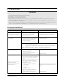
6-1 Electrical Malfunction
SYMPTOM
CAUSE
CORRECTIONS
Oven is dead.
Fuse is OK.
No display and no operation at all.
1. Open or loose lead wire harness
2. Open thermal cutout (Magnetron)
3. Open low voltage transformer
4. Defective Ass'y PCB
Check fan motor when thermal cutout is defective.
No display and no operation at all.
Fuse is blown.
1. Shorted lead wire harness
2. Defective primary latch switch (NOTE 1)
3. Defective monitor switch (NOTE1)
4. Shorted HVCapacitor
5. Shorted HVTransformer (NOTE2)
Check adjustment of primary, interlock monitor,
door sensing switch.
Check Ass'y PCB when LVT is defective.
NOTE 1: All of these switches must be replaced at the same time.
(refer to adjustment instructions)
Check continuity of power relay contacts and if it has continuity, replace power
relay also.
NOTE 2: When HVTransformer is replaced, check diode and magnetron also.
Oven does not accept
key input (Program)
Timer starts countdown but no
microwave oscillation.
(No heat while oven lamp and
fan motor turn on.)
Samsung Electronics
1. Key input is not in-Sequence
2. Open or loose connection of membrane
key pad to Ass'y PCB
3. Shorted or open membrane panel
4. Defective Ass'y PCB
Refer to operation procedure.
1. Off-alignment of latch switches
2. Open or loose connection of high voltage
circuit especially magnetron filament
circuit
NOTE: Large contact resistance will bring
lower magnetron filament voltage and
cause magnetron to lower output and/or
intermittent oscillation.
3. Defective high voltage components
H.V.Transformer
H.V.Capacitor
H.V.Diode,H.V.Fuse
Magnetron
4. Open or loose wiring of power relay
5. Defective primary latch switch
6. Defective power relay or Ass'y PCB
Adjust door and latch switches.
Replace PCB main.
Check high voltage component according to
component test procedure and replace if it is
defective.
Replace PCB main.
6-1
Troubleshooting
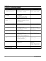
6-2 Electrical Malfunction(continued)
SYMPTOM
CAUSE
CORRECTIONS
Oven lamp and fan motor turn on
1. Misadjustment or loose wiring
of primary latch switch
2. Defective primary latch switch
Adjust door and latch switches.
Oven can program but timer
does not start.
1. Open or loose wiring of secondary
interlock switch
2. Off-alignment of primary interlock
3. Defective secondary interlock S/W
Adjust door and interlock switches.
Microwave output is low;.
Oven takes longer time to
cook food.
1. Decrease in power source voltage.
2. Open or loose wiring of magnetron
filament circuit. (Intermittent oscillation))
3. Aging of magnetron
Consult electrician.
Fan motor turns on when plugged in
Loose wiring of door sensing switch
Check wire of door sensing switch.
Oven does not operate and return
to the plugged in mode.
Defective Ass'y PCB
Replace PCB main.
Loud buzzing noise can be heard.
1. Loose fan and fan motor
2. Loose screws on H.V.Transformer
3. Shorted H.V.Diode
Tighten screws of fan motor.
Tighten screws of H.V.Transformer.
Replace H.V.Diode.
Turntable motor does not rotate.
1. Open or loose wiring of turntable motor.
2. Defective turntable motor.
Check the wire of turntable motor
Replace turntable motor.
Oven stops operation during cooking
1. Open or loose wiring of primary
interlock switch
2. Operation of thermal cutout(Magnetron)
Adjust door and latch switches.
Sparks
1. Metallic ware or cooking dishes
touching on the oven wall.
2. Ceramic ware trimmed with gold or
silver powder also causes sparks.
Inform the customer.
Do not use any type of cookware with
metallic trimming.
Uneven cooking
Uneven intensity of microwave due to
its characteristics.
Wrap thinner parts of the food with
aluminum foil.
Use plastic wrap or cover with a lid.
Stir once or twice while cooking
foods such as soup, cocoa, or milk.
Noise from the turntable motor
when it starts to operate.
Noise may result from the motor.
Replace turntable motor.
6-2
Samsung Electronics
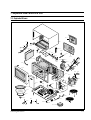
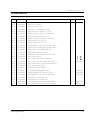
7. Exploded Views and Parts List
7-1 Exploded Views
M17
M2
M3
M1
M54
M55 M4
M53
M5
M52
M13
M14
M7
M6
M8
M10
M11
M9
M51 M49
M15
M16
M67
M68
M18
M12
M50
M20
M19
M56
M24
M25
M22
M26
M29
M27
M47
M21
M30
M46
M57
M45
M58
M44
NC
M31
M48
NO
COM
M33
M34
M36
M37
M28
M35
M59
M38
M60
M65
M39
M61
M40
M63
M62
M64
M43
M41
M66
M42
M23
Samsung Electronics
7-1
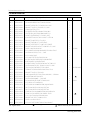
Exploded Views and Parts List
7-2 Main Parts List
Ref. No.
Parts No.
M 1
M 2
M 3
M 4
M 5
M 6
M 7
M 8
M 9
M 10
M 11
M 12
M 13
M 14
M 15
M 16
M 17
M 18
M 19
M 20
M 21
M 22
M 23
M 24
M 25
M 26
M 27
M 28
M 29
M 30
M 31
M 33
M 34
M 35
M 36
M 37
M 38
M 39
M 40
DE70-30001A
DE63-90035H
DE61-50565A
DE61-50564A
DE61-70060A
DE61-30006A
DE47-70031G
DE63-20017A
DE60-40009B
DE61-50021A
DE61-50347A
DE61-50027B
DE61-50570A
DE65-20014A
DE39-20058C
DE71-60448A
DE92-90478C
DE91-40093A
DE31-10156A
DE39-40758A
DE62-90102A
DE71-60447A
DE74-20022A
DE47-20009A
DE61-50490A
4713-001031
DE03-30035A
DE71-60016C
DE63-90090A
DE93-20020D
DE66-40021B
3405-000178
3405-000175
DE66-90054B
DE26-10100A
2501-001019
DE61-50106A
DE59-40001A
DE91-70061A
: Option Parts
7-2
Description/Specification
Q'ty
PANEL-OUTER;SECC,T0.6,360,1128,EPOXY-COATI
CUSHION-RUBBER;DFA20,T2,W190,L200,BLK
BRACKET-UPPER;SECC,T0.5,W362,L294,-,CK95
BRACKET-TCO;SECC1,T0.6,W45,L21,-,CK95
SPRING-PLATE;SK-5,T0.5
SUPPORTER-HEATER;ALUMINA,5G,2ND-W/P
HEATER-GRILL;D6.6,230V1280W,M9G45,SJH
GASKET-HEATER;BRASS,T1.5,OD30.5,ID22.5
WASHER-TEFLON;SLOT,ID22.2,OD28,T1.2,TEFLON
BRACKET-FLANGE;SECC1,T0.8,32,32
BRACKET-EARTH;M16,T1.0,SECC,ZNC3
BRACKET-HEATER;SECC,T1.0,W51,L55,CE945GF
BRACKET-AIR GUIDE;ALCOAT,T0.6,W233.5,L55,-,CK95
CABLE CLAMP;DA-6N,NY-66
ASSY POWER CORD;KKP-4819D/B232,250V16A,L1700,G
COVER-BACK;SCP3(Cr),T0.6,-,-,-,CK95
ASSY-CASING;CK95
ASSY NOISE FILTER;SN-E10D,250V,10A
MOTOR-FAN;SMF-945EA,230/50,2400,M97G45
WIRE HARNESS-A;230V50HZ,CK95
ADIABATIC-RIGHT;SUPER FINE INSULATIO,T3,W213.3
COVER-ADIABATIC;SECC,T0.6,W220.3,L305.1,-,CK95
TRAY-OIL;GLASS(NEOREX) T5,P1210,600G
THERMOSTAT;PW2N-520PB,160/60,250V/7.5A,H,
BRACKET-TCO;SECC1,T0.6,34,58
LAMP-INCANDESCENT;230V,173mA,40W,ORG,-,-,25x69mm
MAGNETRON;OM75PH((31)ESS
COVER-AIR;NYLON#66,-,-,-,BLK,CK95
CUSHION-DOOR;PE-FOAM,T0.5,W420,L420
ASSY BODY LATCH;M959/XSA
LATCH-BODY;NYLON#66(2021SW),40g,M959/XSA
SWITCH-MICRO;250V,15A,200gf,SPST-NO
SWITCH-MICRO;250V,15A,200gf,SPST-NO
LEVER-SWITCH;NYLON#66(2021SW),40G,M959/XSA
TRANS-H.V;SHV-945EG1,230V,2280V/3.15V,50
C-OIL;1.10uF,2100V,BK,35X54X90,20mm
BRACKET-HVC;SECC,T0.8,W31,L125.8
DIODE-H.V;HVR-1X-32B-12
ASSY-H.V.FUSE;THV060T-0800-H,5KV/0.8A,WHT
: Warning
1
1
1
1
1
1
1
1
1
1
1
1
1
1
1
1
1
1
1
1
1
1
1
1
1
1
1
1
1
1
1
2
1
1
1
1
1
1
1
Remarks
P-CORD
CK97B/CK98F
DOOR
:Electrostatically Sensitive Devices
Samsung Electronics
Exploded Views and Parts List
7-2 Main Parts List
Ref. No.
Parts No.
M 41
DE26-20152A
TRANS-L.V;SLV-105E,230V,50HZ,AC17V/3V
1
M 42
DE60-60025A
PIN-FOOT;PP-JI350,BLK
4
M 43
DE61-40065A
FOOT;PP,BLK,T2x22x17mm
4
M 44
DE63-90062C
CUSHION-H.V.T;NR,T18,W30,L50,CK95
1
M 45
DE80-10001D
BASE-PLATE;SGCC,T0.8,W345,L565,-,CK95
1
M 46
DE31-10170A
MOTOR-DRIVE;M2LJ24Z702,ST-16F,220/240V,2.5
1
M 47
DE71-60382A
COVER-CEILING;MICASHEET,T0.5,70,133
1
M 48
DE73-90027A
FERRITE-CORE;NI-ZN,T13.8,W21.0,L28.0,BNF-14
1
M 49
DE72-60005A
GUIDE-AIR;SECC1-P,T0.5,210,225
1
M 50
DE32-10013A
SENSOR-THERMISTOR;PT-312-K2
1
M 51
DE71-60459A
COVER-ADIABATIC-L;SECC,T0.6,W252,L300,-,CK95
1
M 52
DE62-90103A
ADIABATIC-LEFT;SUPERFINE INSULATION,T7,W250,L
1
M 53
DE39-40409A
WIRE HARNESS-E;230V50HZ,M9G45,CTW
1
M 54
DE39-40759A
WIRE HARNESS-B;230V50HZ,CK95
1
M 55
DE47-20009A
THERMOSTAT;PW2N-520PB,160/60,250V/7.5A,M
1
M 56
DE92-40215A
ASSY DOOR;CK95,WHT
1
M 57
DE93-30577A
ASSY CONTROL-BOX;230V50Hz,CK95,WHT
1
M 58
DE74-20105B
TRAY-CRUSTY;T5,P1300,H30,830G,TEFLON-COAT
1
M 59
DE74-20015B
TRAY-COOKING;GLASS,T6.0,PI318,1050G,MW5630T
1
M 60
DE92-90189D
ASSY-GUIDE ROLLER;D19,STD
1
M 61
DE67-60026C
COUPLER;PTFE,12G.WHT,MB245
1
M 62
DE74-40001A
SPIT-BARBECUE;MSWR,CE945G,SNC2
1
CK97B/CK98F
M 63
DE67-60074A
COUPLER-BARBECUE;PTFE,29G,WHT,CE104CF
1
CK97B/CK98F
M 64
DE72-80062A
SHAFT-BARBECUE;STS304,D3,L149,W60.25,CE97
3
CK97B/CK98F
M 65
DE92-90019P
ASSY-WIRE RACK;CE1279KSE,HIGH
1
M 66
M 67
M 68
DE92-90019R
3601-000448
3601-001126
ASSY-WIRE RACK;CE1279KSE,LOW
FUSE-FERRULE;250V,10A,SLOW-BLOW,CERAMIC
FUSE-FERRULE;250V,1.6A,QUICK-ACTING,CERAMIC
1
1
1
Samsung Electronics
Description/Specification
Q'ty
Remarks
CK96T/CK98F
NOISE-FILTER
NOISE-FILTER
7-3
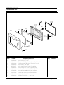
Exploded Views and Parts List
7-3 Door Parts List
D10
D5
D6 D7
D4
D3
D1
D9
D8
D2
D11
Ref. No.
Parts No.
D 1
D 2
D 3
D 4
D 5
D 6
D 7
D 8
D 9
D 10
D 11
DE64-40319A
DE02-00125A
DE67-20184A
DE64-40320A
DE92-50127J
DE61-80002A
DE61-80003A
DE64-40264B
DE61-70148A
DE64-40012C
DE64-90160A
7-4
Description/Specification
DOOR-A;PC,-,WHT,-,CK95
TAPE-DOUBLE FACE;ACRYL,T0.45,W9,WHT,WF103,#4420
SCREEN-DOOR(B);TEMP GLASS,T3.2,W376.7,L241.8
DOOR-SUB;PC,-,BLK,-,CK95
ASSY DOOR-E(SEALANT);CK95,SEALANT,BLK
HINGE-UPPER;SCP1,T2.3,26,77,ZPC3,WHT,CE945
HINGE-LOWER;SCP1,T2.3,26,77,ZPC3,WHT,CE945
DOOR-KEY;NYLON#66(2021SW),40G,-,M959/XS
SPRING-KEY;HSWR3,PI6.0,D0.8,L34.4,BLUING
DOOR-C;PBT,-,BLK,-,CK95
DECORATION-DOOR;PC,-,-,-,-,WHT,-,CK95
Q'ty
Remarks
1
0.05
1
1
1
1
1
1
1
1
1
Samsung Electronics
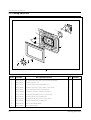
Exploded Views and Parts List
7-4 Control Parts List
C10
C7
C1
C8
C3
C2
C4
C5
C9
C6
Ref. No.
Parts No.
C 1
DE67-40173A
WINDOW-DISPLAY;ACRYL,-,-,-,SMOG,-,CK95
1
C 2
DE66-20276A
BUTTON-MORE;PC,-,-,WHT,CK95
1
C 3
DE66-20277A
BUTTON-DEFROST;PC,-,-,WHT,CK95
1
C 4
DE66-20278A
BUTTON-SELECT(A);PC,-,-,WHT,CK95
1
C 5
DE66-20280A
BUTTON-SELECT(B);PC,-,-,WHT,CK95
1
C 6
DE66-20279A
BUTTON-CANCEL;PC,-,-,WHT,CK95
1
C 7
DE72-70206A
CONTROL-PANEL;PC,WHT,-,-,CK95
1
C 8
DE91-10565A
ASSY PCB-MAIN;RC-CK95-00,230V50HZ,VFD,CK95
1
C 9
DE64-10132C
KNOB;PC,-,WHT,PI28,CK95
1
C 10
DE93-30583A
ASSY CONTROL-PANEL;CK95
1
Samsung Electronics
Description/Specification
Q'ty
Remarks
7-5
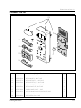
Exploded Views and Parts List
7-5 Casing Parts List
1
2
3
4
5
9
6
10
8
7
11
Ref. No.
Parts No.
1
DE31-10171A
MOTOR-CONVECTION;SMC-105EA,230V/50HZ,2800RPM
1
2
DE31-90019A
BLADE-FAN;SECC,T0.6
1
3
DE47-70077A
HEATER-CONVECTION;230V,1680W,30.7,7
1
4
DE61-50484A
BRACKET-HEATER;STS430,T0.8,W27.2,L26,CE115K
2
5
DE92-90487A
ASSY-COVER CASING;CE115K,230V50HZ
1
6
DE62-90098B
ADIABATIC-CASING;-,T8,W245,L336.8,CK95
1
7
DE72-30016B
BUSH-MOTOR;MSWR3,D5.6,L15.7,CE115K,ZP3
1
9
DE31-90020A
BLADE-FAN;ALSTAR,T0.6,W250,L250
1
8
DE60-40026B
WASHER-PLAIN;ID5.5,OD12,T1.0,SBC1,ZNC3
1
9
DE31-90020A
BLADE-FAN;ALSTAR,T0.6,W250,L250
1
10
DE60-30016A
NUT-FLANGE;M4,MSWR10
3
11
DE92-90478C
ASSY-CASING;CK95
7-6
Description/Specification
Q'ty
Remarks
Samsung Electronics
Exploded Views and Parts List
7-5 Standard Parts List
Parts No.
Description / Specification
Q'ty
Remarks
DE60-10012A
SCREW-TAP TITE;TH,+,3,M4,L10,SWR10,ZPC2,TOOTH
1
N-F-EA
DE60-10012A
SCREW-TAP TITE;TH,+,3,M4,L10,SWR10,ZPC2,TOOTH
1
P-C-EA
DE60-10012A
SCREW-TAP TITE;TH,+,3,M4,L10,SWR10,ZPC2,TOOTH
1
S-M-EA
DE60-10013A
SCREW-ASSY TAP;TH,2S,4,L12,MSWR3,ZPC3,FIBER
1
MO/FAN
DE60-10018A
SCREW-ASSY MACHINE;PH,M4X0.7P,8,MSWR10,SN1,WS
2
B/EATH
DE60-10024A
SCREW-PH;PH,+,M4,L8,MSWR10,ZPC3
2
B/HEAT
DE60-10045A
SCREW-TAP PH;PH,M3,L6,FEFZY
2
MG-TCO
DE60-10069A
SCREW-TAP TH;TH,M4,L10,FRFZY
3
B/UPPE
DE60-10069A
SCREW-TAP TH;TH,M4,L10,FRFZY
1
CV/AIR
DE60-10072A
SCREW-TAP TH;TH,M4,L16,FEFZY,2-SLOT
1
CB-CMP
DE60-10080A
SCREW-WASHER;M5,L12,2S
4
MGT
DE60-10080A
SCREW-WASHER;M5,L12,2S
4
TNS-HV
DE60-10082H
SCREW-A;2S-4X12,TOOTHED
2
B-PLTE
DE60-10082H
SCREW-A;2S-4X12,TOOTHED
2
CN-BOX
DE60-10082H
SCREW-A;2S-4X12,TOOTHED
2
LATCH
DE60-10082H
SCREW-A;2S-4X12,TOOTHED
5
PN-OUT
DE60-10098A
SCREW-ASSY TAP TITE;PH,TC,M4X8,SWRCH18A,ZPC2,GLD,W
1
CV-TCO
DE60-10098A
SCREW-ASSY TAP TITE;PH,TC,M4X8,SWRCH18A,ZPC2,GLD,W
2
M/DRIV
DE60-10122A
SCREW-TAP TH;TAP,TH,2-4X8,FE,FN
2
C-CEIL
DE60-20063A
BOLT-FLANGE;M4,10,ZPC3,YEL,MSWR
2
HI-LOW
DE60-20063A
BOLT-FLANGE;M4,10,ZPC3,YEL,MSWR
2
HI-UPP
DE60-10045A
SCREW-TAP PH;PH,M3,L6,FEFZY
1
-
DE60-10059A
SCREW-TAP TH;TH,M4,L8,SUS410,CR
3
B/MORT
DE60-10061A
SCREW-TAP TH;TH,M4,L8,STS
1
-
DE60-10122A
SCREW-TAP TH;TAP,TH,2-4X8,FE,FN
2
-
DE60-10059A
SCREW-TAP TH;TH,M4,L8,SUS410,CR
4
CV-CAS
DE60-10061A
SCREW-TAP TH;TH,M4,L8,STS
4
CV-CAS
DE60-10012A
SCREW-TAP TITE;TH,+,3,M4,L10,SWR10,ZPC2,TOOTH
1
-
DE60-10098A
SCREW-ASSY TAP TITE;PH,TC,M4X8,SWRCH18A,ZPC2,GLD,W
1
-
DE60-10088A
SCREW-TAP PH;PH,M3,L8,FEFZY,PLAIN
13
Samsung Electronics
7-7
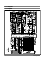
8. P.C.B Diagrams
8-1 P.C.B Diagrams
8-1
Samsung Electronics
P.C.B Diagrams
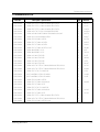
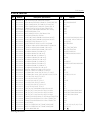
8-2 P.C.B Parts List
No.
Parts No.
Description / Specification
Q'ty
P1
P2
P3
P4
P5
P6
P7
P8
P9
P10
P11
P12
P13
P14
P15
P15
P16
P16
P17
P18
P19
P20
P21
P22
P23
P24
P25
P26
P27
P28
P29
P30
P31
P32
P33
P34
P35
P35
P35
P36
P37
P38
P39
P40
P40
P41
3406-000175
3501-001050
3501-001062
3501-001068
3708-001315
DE07-10096A
DE30-20016A
DE39-40723A
DE61-90034D
0401-001002
0401-001002
0402-001103
0403-000355
0501-000388
0504-001014
0504-001014
2001-000290
2001-000429
2001-000435
2001-000613
2001-000734
2001-000780
2001-000786
2001-000904
2001-001102
2004-000195
2004-000900
2202-000205
2202-000780
2401-000244
2401-000598
2401-000914
2401-001415
2401-001573
2401-002075
2801-003214
3404-000282
3404-000282
3404-000282
3711-000315
3711-000999
3711-001038
DE13-20009A
DE39-60001A
DE39-60001A
DE09-00014A
SWITCH-ROTARY;28V,10mA,DP36T,18.8mm
RELAY-MINIATURE;24VDC,200mW,5A,1FormA,10mS,5mS
RELAY-POWER;24VDC,523.2mW,16A,1FormA,15mS
RELAY-POWER;24Vdc,523mW,16A,1FormA,15mS,10
CONNECTOR-FPC/FC/PIC;12P,2mm,STRAIGHT,SN
V.F.DISPLAY;SVM-07MM09,GRN/ORG,7DIG,112seg
BUZZER;CBE2220BA,STICK
WIRE HARNESS;DC35V,C-959G,80mm,12PIN
HOLDER-DIGITRON;PP(JI350),BLK
DIODE-SWITCHING;1N4148M,100V,200mA,DO-34,TP
DIODE-SWITCHING;1N4148M,100V,200mA,DO-34,TP
DIODE-RECTIFIER;1T4,400V,1A,TS-1,TP
DIODE-ZENER;UZ5.1BSB,5.1V,4.97-5.18V,500mW
TR-SMALL SIGNAL;KSC815,NPN,400mW,TO-92,BK,120TR-DIGITAL;KSR1005,NPN,300mW,4.7K-10K,TOTR-DIGITAL;KSR1005,NPN,300mW,4.7K-10K,TOR-CARBON;10KOHM,5%,1/8W,AA,TP
R-CARBON;1KOHM,5%,1/8W,AA,TP
R-CARBON;1MOHM,5%,1/8W,AA,TP
R-CARBON;3.9KOHM,5%,1/8W,AA,TP
R-CARBON;4.7KOHM,5%,1/8W,AA,TP
R-CARBON;470OHM,5%,1/8W,AA,TP
R-CARBON;47KOHM,5%,1/8W,AA,TP
R-CARBON;620OHM,5%,1/8W,AA,TP
R-CARBON(S);200OHM,5%,1/2W,AA,TP
R-METAL;100Kohm,1%,1/8W,AA,TP,1.8x3.2m
R-METAL;4.7Kohm,1%,1/8W,AA,TP,1.8x3.2m
C-CERAMIC,MLC-AXIAL;22pF,5%,50V,SL,TP,1.9x3.5
C-CERAMIC,MLC-AXIAL;100nF,+80-20%,50V,Y5V,TP,3.5x1
C-AL;100uF,20%,10V,GP,TP,6.3x7,5
C-AL;1uF,20%,50V,GP,TP,4x7,5
C-AL;22uF,20%,16V,GP,TP,5x11,5
C-AL;470uF,20%,35V,GP,TP,10x20,5
C-AL;47uF,20%,50V,GP,TP,6.3x11,2.5
C-AL;4.7uF,20%,50V,GP,TP,5x11,5
CRYSTAL-UNIT;4.194304MHz,50ppm,28-AAA,12pF
SWITCH-TACT;12Vdc,50mA,120+-30gf,6.2x3.6mm
SWITCH-TACT;12Vdc,50mA,120+-30gf,6.2x3.6mm
SWITCH-TACT;12Vdc,50mA,120+-30gf,6.2x3.6mm
CONNECTOR-HEADER;1WALL,7P,1R,3.96mm,STRAIGHT,SN
CONNECTOR-HEADER;BOX,5P,1R,2.5mm,STRAIGHT,SN
CONNECTOR-HEADER;BOX,6P,1R,2.5mm,STRAIGHT,SN
IC;KA7533,DIP
WIRE-SO COPPER;PI0.6,SN,T,52MM,TAPING_WIRE
WIRE-SO COPPER;PI0.6,SN,T,52MM,TAPING_WIRE
IC-MCU;M38127M8-149
1
4
1
2
1
1
1
1
1
8
7
3
3
1
4
4
5
7
1
2
1
3
8
1
3
1
1
2
5
1
1
2
1
1
1
1
5
5
4
1
1
1
1
8
2
1
Samsung Electronics
Remarks
ECD1
RY02,RY03,RY04,RY05
RY01
RY06,RY07
CN05
VFD1
BUZ1
CN06
D03,D04,D05,D06,D08,D09,D10,D11
D12 ,D13,D14 ,D16,D17,D18,D19
D01,D02,D07
ZD01,ZD02,ZD03
TR01
TR02 ,TR03,TR04,TR054
TR06,TR07,TR08,TR09
R14,R15,R18,R22,R23
R07,R08,R09,R16,R20,R21,R33
R10
R06,R11
R32
R01,R02,R17
R24,R25,R26,R27,R28,R29,R30,R31
R19
R03,R04,R05
R13
R12
C12,C13
C08,C09,C10,C11,C14
C03
C05
C04,C07
C01
C02
C06
XTL1
SW01,SW02,SW03,SW04,SW05
SW06,SW07,SW08,SW09,SW10
SW11,SW12,SW13,SW14
CN03
CN01
CN02
IC02
J01,J02,J03,J04,J05,J06,J07,J08
J09,J10,J11
IC01
8-2
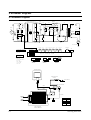
9. Schematic Diagrams
9-1 Schematic Diagrams
ASSY CHOCK P.C.B
MGT
T.C.O
BRN
F
Thermistor
Sensor
WHT
N
L.V.T
CONV
MOTOR
RELAY
ORG
H.V.D
COM
CONV
MOTOR
FAN
MOTOR
0V
BLU
CM
FAN
MOTOR
RELAY
0.1uF+120ohm
DRIVE MOTER
LAMP
2200pF
BLU
YEL
FM
NO
H.V.C
MONITER
SWITCH
NC
H.V.FUSE
(0.8A)
RED
YEL
CONV
RELAY
GRILL
RELAY
BLK
BLU
DM
ORG
WHT
BLU
PNK
BLU
MONITER
FUSE (1.6A)
BLK
L
E
500K
WHT
WHT
1mH
2200pF
CONV
HEATER
V/G
GRILL
HEATER
BLK
H.V.T
YEL
LIN-CAPACITORT 0.1uF
GRILL
T.C.O
230V~
50Hz
BRN
WHT
RED
FUSE 10A
BLK
L
BRN
PRIMARY
SWITCH
BRN
BRN
INRUSH
RELAY
MAIN
RELAY
RESISTOR
ORG
F
FA
BLU
BLU
BLU
POWER
RELAY
MAGNETRON
DOOR IS OPENED
COOK OFF
Power Conv Motor Fan Motor
Relay
Relay
Relay
Inrush
Relay
Door Sensing
Switch
Conv Heater
Relay
KEY BOARD
ORG
CONDITION OF OVEN
Main
Relay
Thermistor
Sensor
GRN
ORG
Grill Heater
Relay
A S S Y M A I N P.C.B
WIRING COLOR
BRN : BROWN
WHT : WHITE
RED : RED
Y/G : YELLOW/GREEN
BLU : BLUE
ORG : ORANGE
YEL : YELLOW
PNK : PINK
COM NO
BRN RED
WHT YEL
NC
COM NO
ORG
COM NO
ORG
PRIMARY LATCH
SWITCH
RED BLU
BRN
WHT
MONITOR
SWITCH
DOOR SENSING
SWITCH
MAGNETRON
HIGH VOLTAGE
DIODE
FA
TO CHASSIS
F
HIGH VOLTAGE CAPACITOR
RED
RED
RED
H.V.FUSE
BLK
WHT
RED
SYMBOL COLOR
BRN BROWN
BLK
BLACK
RED
RED
BLU
BLUE
HIGH VOLTAGE
TRANSFORMER
9-1
Samsung Electronics