1
Issue 1.02
Doortello Business
USER GUIDE
User guide
Doortello Business
Doorphone with analogue
telephone line interface and
up to 127 chime bottons and
1 dial pad
FW T2.05W2.04 or better
Page 1
Issue 1.02
Doortello Business
User guide
Contents
Introduction .......................................................................................................................................................................... 3
Description ............................................................................................................................................................................ 3
Package content .................................................................................................................................................................... 5
Features ................................................................................................................................................................................. 5
Installation ............................................................................................................................................................................ 6
Security advices .................................................................................................................................................................... 7
Flush and wall mounted installation ..................................................................................................................................... 7
Behind panel installation ...................................................................................................................................................... 7
Cabling of the chime buttons ............................................................................................................................................... 8
Further connectors ................................................................................................................................................................ 9
Telephone line (A/B) ............................................................................................................................................................ 10
RS 485 serial interface (C/D) ................................................................................................................................................ 10
Driver contact 1 and 2 (E/F; G/H) ......................................................................................................................................... 10
External DC power supply (I/L) ............................................................................................................................................ 10
Power supply over the telephone line ................................................................................................................................ 11
Automatic heating element ................................................................................................................................................ 12
Line impedance ................................................................................................................................................................... 12
DB Bus ................................................................................................................................................................................. 12
Volume adjustment ............................................................................................................................................................. 12
First activation .................................................................................................................................................................... 13
Programmation ................................................................................................................................................................... 15
Activate the programming mode ....................................................................................................................................... 15
Tones during programmation ............................................................................................................................................. 16
Default data load ................................................................................................................................................................ 17
Chime buttons and functional keys .................................................................................................................................... 17
Delete telephone number and functional keys ................................................................................................................... 19
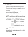
Speed dial numbers ............................................................................................................................................................ 20
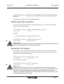
Delete speed dial numbers ................................................................................................................................................. 21
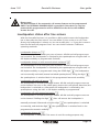
Automatic call answer ........................................................................................................................................................ 21
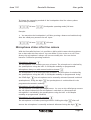
Loudspeaker status after line seizure .................................................................................................................................. 22
Microphone status after line seizure .................................................................................................................................. 23
Automatic hang up after driver contact activation ............................................................................................................ 24
Speakerphone operational mode ........................................................................................................................................ 24
Maximum number of digits input from dial pad ................................................................................................................ 25
Password ............................................................................................................................................................................. 26
Access codes ....................................................................................................................................................................... 26
Driver contacts activation codes ......................................................................................................................................... 28
Maximum line seizure time ................................................................................................................................................. 28
Dial pause time ................................................................................................................................................................... 29
Driver contacts activation time ........................................................................................................................................... 30
Interdigit dial pause ............................................................................................................................................................ 30
Keypad activation time ....................................................................................................................................................... 31
Keypad blocking time ......................................................................................................................................................... 31
Blocking time increase ........................................................................................................................................................ 32
Maximum number of attempts ........................................................................................................................................... 33
Flash time ............................................................................................................................................................................ 34
Busy tone detection ............................................................................................................................................................ 34
Ring back tone detection .................................................................................................................................................... 35
Number of rings .................................................................................................................................................................. 36
Tone tables .......................................................................................................................................................................... 36
How to use .......................................................................................................................................................................... 40
Calling a phone using a chime button ................................................................................................................................ 40
Calling a phone using the dial pad ..................................................................................................................................... 40
Calling a phone using a speed dial ..................................................................................................................................... 40
Access code ......................................................................................................................................................................... 41
Direct activation of a driver contact ................................................................................................................................... 41
Incoming call to the doorphone ......................................................................................................................................... 42
Call termination .................................................................................................................................................................. 42
Code digits for the phones ................................................................................................................................................. 42
Optical indicators ................................................................................................................................................................ 43
Trouble shooting ................................................................................................................................................................. 44
Technical data ..................................................................................................................................................................... 46
Programming codes overview ............................................................................................................................................ 47
Overview of programmed values ........................................................................................................................................ 49
Page 2
Options ............................................................................................................................................................................... 57
Issue 1.02
Doortello Business
User guide
Introduction
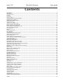
The Doortello Business is a door phone system for integration with new or existing
telephone systems. The door phone has a analogue telephone line interface a can
be connected to any type of transmission technology, as far as a specific adapter is
available, like ISDN, VoIP, GSM, DECT and similar systems. Pressing a chime button,
or dialling a number using the key pad, a programmed telephone number, or the
dialled digits, are sent as DTMF tones to the telephone line. Up to 127 chime
buttons can be connected to the system. Each of them can have a 16 digits long
telephone number stored in the system. When the dialled extension will answer
the call a speech connection is established. A smart tone detection program
ensures that the connection is surely terminated recognizing a busy tone, or in
case of a missing answer after a specified number of ring back tones.
The door phone is approved for the use within the European community as
defined by the 98/482/EU (TBR 21) on the analogue telephone network. This is not
a warranty that the device can work with all European telephone networks, which
might slightly differ from the standard.
If you notice functional problems with your telephone line please get in contact
with your local dealer.
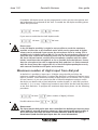
Doortello Business
doorphone
PABX
Analogue or digital
telephone
Doortello Business. Functional overview.
Description
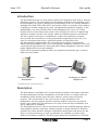
The door phone is available as ES version behind a stainless steel plate with holes
for the loudspeaker and the microphone and as BG version as compact unit for
installation inside existing cases like door stations, letter boxes and similar
systems. The construction of the unit ensures an easy installation. The
loudspeaker, the microphone and the controller and all connectors are placed
inside a very small case. This will ensure not only a fast and easy installation, but
also a high level of reliability.
The Doortello Business ES version has been design to be installed together with his
own modular stainless steel door station program. A large selection of different
modules like chime buttons, dial pad, information and frames with boxes for the
flush or surface mounting, as well as pedestals, are available to realise many
different installation solutions. The BG version allows the installation on the back
Page 3
Issue 1.02
Doortello Business
User guide
of an existing speakerphone grid, i.e. inside existing old door stations, customer
designed installations, parking house information systems, etc. Using the plastic
adapter frames it is also possible to the install the ES modules in existing letter
boxes or pedestals.
The door phone needs to be connected to a analogue telephone line using two
wires, further the optional external power supply can be use to power the
illumination and the heating element of the unit. The modules of the door station
are connected together using the internal DB bus. Fir the BG version an external
chime button encoding unit is available to connect them to the DB bus. Up to 127
single chime button and a dial pad with 16 buttons (12 for the dial and 4 free
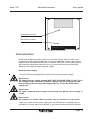
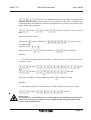
100 mm
Volume control
92 mm
Microphone
Loudspeaker Connections Line impedance
DB Bus
ES speakerphone. Front and back view.
programmable functional buttons) can be connected to the Doortello Business
door phone using the DB bus.
The unit has also two integrated dry driver contacts to command door openers or
other applications, like video cameras. A serial RS 485 interface for the connection
of peripheral expansion units completes the connection block of the device.
The programming of the telephone numbers and all other features are done using
a DTMF dial. A complete description of the programming can be found in the
chapter Programming.
Page 4
Issue 1.02
Doortello Business
User guide
Package content
The content of the package for the DB 01 Doortello Business BG behind panel door
phone (Part no. 20-2000-0001) includes:
- Door phone with box
- Encoding unit for 4 button with flat cable
- This user guide (german/english)
- Multilanguage short user guide
- Multilanguage user guide for the encoding unit
- Return notice and error description
- Small screwdriver
The content of the package for the DB 02 Doortello Business ES door phone (Part
no. 20-2000-0005) includes:
- Door phone wit stainless steel panel
- This user guide (german/english)
- Multilanguage short user guide
- Return notice and error description
- Small screwdriver
Features
- Up to 127 chime buttons (dry contacts) can be connected. For each button a 1 to
16 digits long telephone number (1-0,*,#, flash, pause) can be stored.
- Dial pad for the dial of telephone numbers, speed dial codes or access codes with
4 programmable functional buttons
- Speed dial for 100 numbers
- Programming using DTMF code with password function (remote programming)
- Programmable driver contacts activation time (0 to 99 seconds)
- RISC processor controlled state-of-the-art speaker phone
- Speech detection
- Programmable ring back and busy tone detection
- Programmable automatic call answer
- Programmable ringing time from 1 to 99 calls
- Volume adjustment for microphone and loudspeaker
- 2 integrated driver contacts with DTMF dial activation (door opener function)
- Programmable door opener DTMF codes
- Programmable automatic driver contact activation with button pressure
- Integrated heater
- Manual disconnection with DTMF dial
- Programmable automatic disconnection after door opening
- Suppression of DTMF tone input from outside
- Connection to a standard analogue telephone line, two wires
- DTMF dial
- Programmable max. connection time fro 1 to 999 seconds
Page 5
Issue 1.02
Doortello Business
User guide
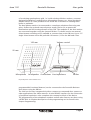
Installation
Surface mounted
installation with stainless
steel cas and weather
protection
Behind panel
installation
Surface mounted
installation with FLAT
box
Installation as
stand alone
pedestal
Doortello Business. Many way to install the system
Before you start with the installation please read the following indications:
- The Doortello Business ES can, together with his modular door station program,
has a IP 55 protection degree and can be installed also outside.
- If you plan an installation in a rainy environment we suggest the use of a
weather shelter or a surface mounting box with weather shelter.
- With surface mounted and pedestals installation we suggest always the use of
the integrated heating element (12 Vdc external power supply is needed). This is
also valid for the BG version.
- If a fluid gets inside the unit disconnect at once the telephone line and the
external power supply (if installed).
- The device can only be maintained by instructed specialized technicians.
- Static discharges may damage the device. Please ensure that you are grounded
before any activity with the unit.
Page 6
Issue 1.02
Doortello Business
User guide
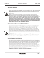
Security advices
Please read carefully this user guide before you install the unit. Take care about the
security advices. Diregarding the warnings may be against existing laws or cause
dangerous situations.
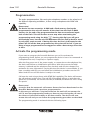
Please note!
Think any time during installation at your own safety! Be careful and
disconnect the 230 V power supply before connecting the external power
supply unit. Before you touch any cable ensure that no voltage is present on
the line. Please consider that it can be against safety rules to run low and
high power cables in the same duct. An installation of 230 V cable inside the
door station is forbidden by law. If you have to drive high power circuits with
the internal driver contact of the device you have to use external high power
relais (like the 1471, see also the chapter Options)
Flush and wall mounted installation
For the flush and wall mounted installation of the device the modular Doortello
Business door station has to be used. This program offers you a wide range of
different flush and wall mounting cases, as well as different pedestals. The
Doortello Business ES device is installed as one of the modules of the modular
door station. The single modules are conneted together using the delivered flat
cable. More details about the installation of the Doortello Business modular door
station can be found in the documentation delivered with the cases and modules.
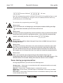
Please note!
NEVER install a ES version behind an existing panel. This might cause heavy
disturbances to the speaker phone making his use impossible. For behind
panel installation use only the BG version!
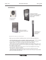
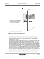
Behind panel installation
The requisite for the installation of the Doortello Business BG version is that there is
already an exiting plate with a speaker grid available. The Doortello Business BG has
been especially developed for this type of use. As the form and technical details of
the plat with the speaker grid may differ from side to side we don’t have the
possibility to provide here precise installation instructions. It is very important that
the microphone is placed precisely in correspondence with a hole to the outside. If
necessary a hole has to be drilled. For a better speech quality of the speaker phone
the unit has installed flush fitted with the plate.
Using the available plastic frame adapters also the ES module can be used for
installation in letter boxes, pedestals and similar installations.
Page 7
Issue 1.02
Doortello Business
User guide
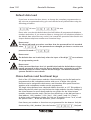
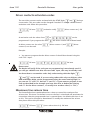
Attention! The microphone
must be coincide exactly
with a hole in the plate.
Doortello Business. Behind panel installation
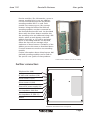
Cabling of the chime buttons
As already mentioned the chime button module are connected with the
Doortello Business ES unit using the flat cable of the DB bus. Up to 32 chime
button modules can be connected. please consider that the last module can
have only 3 button. This mean that you can have up to 127 chime buttons
connected to the system.
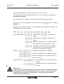
Each button has a decimal address form 001 to 127. This addresses are allocated
using the DIP swith that you can find on the chime button modules. Each DIP
switch selection allocates 4 fixed addresses for each module. I.e. the frist modul
will have the addresses from 001 to 004, the second one from 005 to 008, and so
on. If the module you are addressing is not fully equipped with all four buttons,
i.e. if you are using modules with 1, 2 or 3 buttons only, you will loose the address
which are not used. I.e. if the first module has only two buttons only the addresses
003 and 004 are used. The addresses 001 and 002 are lost. If the second module
has only 3 buttons only the addresses 006, 007 and 008 are used, the address 005
is lost.
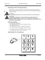
The dial pad module is recognized automatically by the device and for the 4
programmable button, which can be find of the module, for fixed addresses will
be assigned: 128 („handset“), 129 („key“), 130 („name“) und 131 („lamp“).
Page 8
Issue 1.02
Doortello Business
User guide
Passive modules, like information, spare or
camera modules don’t use any address.
For the Doortello Business BG the button
encoding module DB 15 is used. Each
module can connect up to 4 dry contact
buttons. Using the DB bus flat cable all
encoding modules are then connected to
the Doortello Business BG unit. As described
above with the chime button modules also
the encoding units are addressed using a DIP
switch, where at each button a decimal
address form 001 to 127 will be assigned.
Up to 32 encoding modules can be used,
where the last one can manage only a
maximum of three buttons. Limitation of the
address use are the same as described above
if not all buttons are used on one encoding
module.
Further information about chime button, dial
pad and encoding modules can be find on
the specific user guide of that products.
Chime buttons modules with DB bis cabling
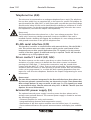
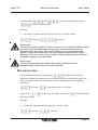
Further connectors
Telephone line (A/B)
RS 485 serial interface (C/D)
Driver contact 1 (E/F)
Driver contact 2 (G/H)
External DC power supply (I/L)
Line impedance 600 Ohm
Line impedance Zr (TBR 21)
DB Bus
Anschlüsse Doortello Business Grundsystem
Page 9
Issue 1.02
Doortello Business
User guide
Telephone line (A/B)
The unit must be connected to an analogue telephone line to work. The telephone
line can be a public line, an extension line or the input of a specific FXO adapter for
special networks like GSM, DECT or VoIP. Please take care that the open line voltage
should not be below 20 Vdc and it should be able to delivery a minimum of 18 mA
during the seizure. For the best speaker phone functionality select also the correct
line impedance (read also the chapter Line impedance).
Please note!
The Doortello Business door phone has a „fine“ over voltage protection. This is
useful only if more over voltage protection circuits are installed. If the unit is
installed outside a building we suggest the installation of a over voltage protector
with ground connection on the specific telephone line.
RS 485 serial interface (C/D)
This interface is used for a communication with external devices, like the DB RU 1
unit. This unit has two more relays contacts which can be used instead of the
integrated ones to drive special applications (like TTL signals) or for the remote
control of the door opener if enhanced security is required. The RS 485 interface
can address up to 255 peripheral units.
Driver contact 1 and 2 (E/F; G/H)
The driver contacts can be used to open doors or other functions like the
activation of a video camera. As default the first driver contact is activated
pressing the DTMF digit „7“ during the conversation, and the second driver
contact with the digit „8“. Other ways to work are possible, like the automatic
activation with line seizure or after pressing a specific button. Also the activation
codes can be programmed, i.e. to make the door opening dependent from the
input of a code from the telephone. Read also the chapter Programming for more
information.
Please note!
The two driver contacts integrated in the Doortello Business door phone are
dry but not galvanic contacts as they are electronic circuits. That means that
diver voltage below 6 V may not work. In this case (i.e. TTL signals) you need
to use external relays, like the universal relay 1471 or DB RU 1 device (see also
Options for more information).
External DC power supply (I/L)
The optional external power supply is used to power the door phone and to
activate some optional features. The external power supply is needed to activate
the following functions:
- Enhanced amplifier for noisy environments;
- Integrated heating element with temperature control;
- Illumination of the door station modules over the DB bus (max. 12 modules);
- Future enhanced features like speech announcements and display (not available
yet).
Page 10
Issue 1.02
Doortello Business
User guide
The external DC power supply must have a voltage range form 8 to max. 12 Vdc
stabilized. We suggest you the use of the our power supply unit PRS 231S or the
DB RU 1 unit (see also chapter Options).
The external power supply is also used to power the LED illumination of the door
station modules. Using the DC input on the door phone only 12 modules can be
powered over the DB bus. If more modules are installed a separate power supply
has to be used. In this case the door station modules have the jumper which is
used to separate the power line between the modules. For the power supply of
the modules you can find a screw connector on each unit. For more information
please read the specific documentation of the single modules.
Please note!
With installations at sites with extreme weather conditions, as well with wall
mounted and pedestals installations we suggest in any case the power supply
of the door phone to activate the integrated heater element.
Please note!
The external power supply MUST be stabilized. The voltage MUST NOT exceed
12 Vdc. Higher voltage will destroy the unit!
Please note!
If you are installing more door phone on the same site a separate power
supply unit has to be used for each door phone. Connecting more door
phone with the same power supply unit may damage the devices and will
short circuit the telephone lines!
Please note!
The door station modules can be powered also with 12 Vac. Please ensure
that the voltage used does not exceed 13,8 Vpp. A higher voltage may
destroy the modules. If using an external voltage to power the modules
PLEASE ENSURE THAT THE SEPARATION JUMPER IS OFF ON THE FIRST MODULE.
If not applying the external voltage to the modules WILL DESTROY the door
phone!
Power supply over the telephone line
The Doortello Business door phone has been designed to work as well using the
telephone line only. In this case the device is powered by the telephone line itself.
Using the telephone line only the door opener and the modules LED illumination
are to powered separately. In this case only a AC power supply is needed as the
module can power the LED also using a transformer only. Please refer to the
specific user guides for more information.
Please note!
For specific functions, like the dial of a flash signal, the telephone line has to
be interrupted for a short time. To ensure that the processor inside the device
are still powered during this time, if only a power supply over the telephone
Page 11
Issue 1.02
Doortello Business
User guide
line is used, a larger capacitor has be installed. This capacitor has to loaded at
the first activation of the device. As the processor can not work until this
capacitor is loaded the unit will take some time as only the idle current of the
telephone line can be used. This is only a few µA and it will take some
minutes time to load the capacitor. If you want to shorten this time you have
to call the device. Please read the chapter First activation for more details.
Please take care that some feature may differ if the unit is externally powered or
not.
Line impedance
For a better sound quality of the speaker phone you need a perfect line impedance
adaptation. The line impedance jumpers is therefore available to select the
impedance of the telephone line you are using. You can choice between 600 Ohm
(default) and Zr line impedance. Which type of line impedance you can normally be
read in the technical documentation of the telephone switch or adapter you are
using. Normally small switches and adapter have 600 Ohm, large switches and
public telephone line (in Europe) have Zr. IF you are not sure which lien impedance
you have just use the selection which gives you the best results.
DB Bus
The DB bus connectors is used to connect the different modules of the door station
system to the door phone using a flat cable.
Automatic heating element
If the device is externally powered an automatic integrated heating element will be
activated. This is used to ensure a correct functionality with outside temperature
down to - 20°C. The heating element is activated automatically at +10°C and will be
deactivated at +20°C.
Volume adjustment
On the Doortello Business you can adjust the volume of the microphone and the
loudspeaker. If the volume of the loudspeaker is not high enough you can enhance
this by powering the unit (read also the chapter External DC power supply for
more information).
Please note!
Without an external power supply it can happen that with very high
loudspeaker volume and noises (i.e. feed back noise) the telephone line
current not enough is to support the module. In this case the device will
automatically reduce the loudspeaker volume.
Page 12
Issue 1.02
Doortello Business
User guide
Loudspeaker volume
Microphone volume
Doortello Business volume adjustment
First activation
Install and configure the door station as you wish. Ensure that you follow the
instructions of the single modules for a correct installation. Connect the module
together with the delivered flat cable, if needed. Select the correct addressing of
the module as described. After this you can connect the door phone with the
telephone line and the external power supply.
External power supply
- Connect FIRST the telephone line and then the external power supply.
Please note!
The external power supply voltage MUST NOT BE HIGHER THEN 12 Vdc! Check
the voltage using a voltmeter! A higher voltage may seriously damage the
device voiding you warranty! We suggest the use of out PRS 231S power
supply unit.
Please note!
You need a separate power supply unit for each door phone you are going to
install!
Please note!
The connector I/L doesn’t have a polarity. You can connect +/-as you wish.
- After you switch on the power supply the unit will follow an internal start up
procedure. This may take some seconds. If you have a module with LED (like the
Page 13
Issue 1.02
Doortello Business
User guide
key pad module) you can follow the start up procedure sequence as following
described:
- Red LED is on: main processor is activated, the telephone line is checked (voltage,
noise);
- Red and green LED are on: the RISC processor is activated and will be
synchronised with the main;
- Red LED is on: the memory is checked, if no data are stored a default data load is
executed, if data are already stored they will be uploaded from the flash to the
working memory;
- Both LED are off: the device is now ready to work.
Power from telephone line only
-
Connect the analogue telephone line;
Call the unit;
After a few calls (between 3 and 10) the unit will answer the call;
The unit will now go through the initialisation procedure as described above;
An the end the call will be terminated and you will get a busy tone;
The device is now ready to work.
Please note!
If the door phone is powered from the telephone line only it can happen that
after a power failure or the disconnection of the telephone line that the
device will take some minutes before it will be ready again to work. If you
want to shorten this time you have to go the above described procedure
again. Refer also to the chapter Power supply over the telephone line for
more details.
Page 14
Issue 1.02
Doortello Business
User guide
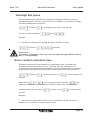
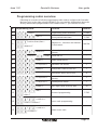
Programmation
The entire programmation, like storing the telephone numbers or the selection of
the different operating modalities, is done using a telephone with DTMF dial
capability.
Please note!
The device has two memories. A RAM and a flash memory. During the
programmation the unit will transfer all the data from the flash to RAM
memory. At the end of the programmation the data are transferred again
back to the flash. This will be done at one step when terminating the
programming mode using the digit
. Pressing this digit you will get a
acknowledge tone, but the unit will disconnect the lien and go back to stand
by only after some seconds. If during this time the line is interrupted or the
power will fail all the data programmed up this point will be lost. If you are
doing a larger programmation we suggest to make a data storage from time
to time.
Activate the programming mode
If you want to program the Doortello Business you to first activate the
programming mode. Before you can program the device it has to be connected to
a telephone line and, if required, to a power supply.
After the first power on of the power supply, or connection to the telephone line,
the device will follow an initialisation procedure. With this process the RAM
memory is deleted and the telephone line checked, read also the chapter First
activation for more information. During this time the device is not available. If you
have a module with LED you can follow the initialisation procedure on the LED.
When both LED are off the device is ready to be used.
Call now the unit using a phone with DTMF dial capability. The device will answer
the call and sent a short tone. The red LED (if installed) will go on and then the
green LED (if installed) on and the red LED (if installed) off when the unit is ready
for speech.
Please note!
It may be that the automatic call answer feature has been deactivated on the
Doortello Business with a previous programmation.
In this case you will hear a ring back tone but the until will not answer the
call. To start the programming mode you have to press during the call one of
the chime or functional buttons at the door station. The device will now
answer the call and you can follow the programming procedure as described.
The programming mode is activated with the following input:
Page 15
Issue 1.02
Doortello Business
Password (default
User guide
) OK tone
Now the programming mode is activated. The red LED (if installed) will go on and
the green LED (if installed) off. The green LED (if installed) will flash with every
positive detection of a DTMF digit.
To terminate the programming mode dial
.
Please note!
If you terminate the call hanging up the handset without dialling the digit
all the data inserted up to this time will be lost!
Please note!
It may be that the programming mode activation using a password has been
deactivated with a previous programmation. Is this case the programming
mode is activated just after the input of the
digits.
Please note!
The password could has been changed. If you hear a NOOK tone you have a
wrong password.
Please note!
As soon as the device will answer the call a maximum connection timer will
start. This is set as default at a value of 60 seconds. At the end of this time
the unit will disconnect the line. All data inserted until this time will be lost.
We suggest you to change this time if you plan an extensive programmation.
Please note!
When you terminate the programming mode with the digit
all
programmed data will be transferred from the RAM to the flash memory. This
will take about 30 seconds. During this time the device is not available.
Tones during programmation
During programmation you will hear the following tones:
Answer tone: 1 short tone. Is sent when the call is answered and the unit ready
to accept more commands.
OK tone: 3 short tones. The data input or command is correct.
NOOK tone: 6 short tones. The data input or command is not correct, last data
input is lost.
Error tone: 9 short tones. There was an error on the device memory. Data could
not be stored and are lost.
Page 16
Issue 1.02
Doortello Business
User guide
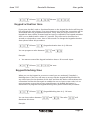
Default data load
If you have to move the door phone, to change the complete programmation or
the unit was programmed wrong you can load the factory default data using the
following procedure:
OK tone
OK tone
Please take care that the default data load will delete all programmed telephone
numbers and values. If you want to delete or change just one telephone number is
the default data reload not very useful. Use instead the procedure described in the
chapter Delete telephone number and functional keys.
Please note!
The above indicated procedure considers that the password has his standard
value
. If the password was changed you have to use the new
password instead of
.
Please note!
The default data are loaded only after the input of the digit
to terminate
the programming mode.
Please note!
If the password has been lost it is possible the load the default data using a
master password. In this case the factory default data a reloaded as well the
standard password. Please contact Rocom Energie- und Kommunikationssysteme GmbH for more details.
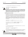
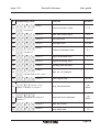
Chime buttons and functional keys
Each of the 127 chime buttons and the 4 functional keys on the dial pad can be
programmed to dial a telephone number with up to 16 digits. Also special
functions can be assigned to the buttons, and sometime also special functions
together with a telephone number can be programmed.
The single chime buttons have a decimal address from 001 to 127. This address is
defined by the DIP switch you can find on the single modules (see also Cabling of
the chime buttons for more details and the user guides for the chime button
modules and the encoder units). The four functional keys on the dial pad have a
fixed address: 128 („handset“), 129 („key“), 130 („name“) und 131 („lamp“).
As digits inside a telephone number you can use all numbers from 1 to 0, as well
the special codes * , # and the functions „flash“ and pause.
From factory no numbers or functions are programmed for the buttons. Only the
functional key 128 („Handset“) has the function
„Dial pad
Page 17
Issue 1.02
Doortello Business
User guide
activation for DTMF dial“ and the 129 („Key“) has the function
„Dial pad activation for access code entry“ programmed
from factory as default.
To program the chime buttons and functional keys follow this procedure:
OK tone {telephone number of function}
{button address}
OK tone
As digit for the telephone number (max 16 digit for each telephone number) the
following values can be entered:
Digits:
,
,
Special dial functions:
,
,
,
,
,
, will dial the code
,
,
;
(is considered as 1
digit);
, will dial the code
(is considered as 1
digit);
, will make a dial pause of 2 seconds (default
value) duration (is considered as 1 digit);
, will send a „Flash“ (short line interruption,
„Recall“ button) of 80 ms (default value)
duration (is considered as 1 digit);
Functions:
, activates the dial pad for a DTMF dial;
, activates the dial pad for the speed dial entry;
, activates the dial pad for a function entry (i.e.
access code entry);
Special functions:
, activates the relay 1 after pressing the
button;
, activates the relay 2 after pressing the
button.
Please note!
A function can be programmed only for button where no telephone number
is programmed. After the programmation of a function no more inputs or
programming are possible for this button. A new programmation will
overwrite the existing data.
Page 18
Issue 1.02
Doortello Business
User guide
Please note!
A special function can be programmed also for button where a telephone
number is already programmed. You can i.e. program a button to dial a
number and in the same time to activate a relay to command an external bell.
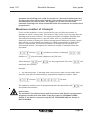
Examples:
The chime button 1 must dial the number 13. As your PBX has an automatic
trunk selection feature activated you must dial a flash to switch from external to
internal dial. To ensure the correct dial after the flash a pause has to be inserted.
Programmation:
n
OK tone
OK
tone
This number will use 4 of the 16 available digits.
The chime button 4 must dial the number 15 and activate at the same time
the relay 2. Programmation:
n
OK tone
OK tone
OK tone
,
OK tone
This number will use 2 of the 16 available digits.
Delete telephone number and functional keys
Each chime button and the 4 functional keys on the dial pad can be deleted one
by one. To delete on button please follow the procedure:
OK tone
{button address} OK tone
Example:
n
You want to delete the chime button 5. Input:
OK tone
OK tone
Please note!
If you want to reprogram a chime or functional button you DON'T have to
delete it first. The new programmation will overwrite the existing one.
Page 19
Issue 1.02
Doortello Business
User guide
Speed dial numbers
The dial pad can be use to dial telephone numbers and/or speed dial codes. This
function is free programmable (read also Chime buttons and functional keys
programmation). If needed you can use also both functions programming the
functional buttons on the dial pad or chime button modules. If you select the speed
dial function you can enter a two digits long code on the dial pad. This code will
then dial a up to 16 digits long stored telephone number on the telephone line.
The speed dial codes can be 00 tp 99, this means that you have up to 100 speed dial
locations available.
As digits inside a telephone number you can use all numbers from 1 to 0, as well
the special codes * , # and the functions „flash“ and pause. From factory no
numbers are programmed in the speed dial locations.
To program the speed dial numbers follow this procedure:
OK tone {telephone number}
{speed dial code} OK tone
As digit for the telephone number (max 16 digit for each telephone number) the
following values can be entered:
Digits:
,
,
,
Special dial functions:
,
,
,
,
, will dial the code
,
,
;
(is considered as 1
digit);
, will dial the code
(is considered as 1
digit);
, will make a dial pause of 2 seconds (default
value) duration (is considered as 1 digit);
, will send a „Flash“ (short line interruption,
„Recall“ button) of 80 ms (default value)
duration (is considered as 1 digit);
Codes: from
to
Example:
The speed dial code 65 must dial the telephone number 66000. As your PBX
does not have an automatic trunk selection feature activated you must dial a 0 to
size the trunk. To ensure the correct dial after the trunk sizing a pause has to be
inserted. Programmation:
n
Page 20
Issue 1.02
Doortello Business
User guide
OK tone
OK tone
This number will use 7 of the 16 available digits.
Delete speed dial numbers
Each of the 100 speed dial code can be delete one by one. To delete a speed dial
number follow this procedure:
OK tone
{speed dial code} OK tone
Example:
n
You want to delete the speed dial entry. Input:
OK tone
OK tone
Please note!
If you need to reprogram an existing speed dial code you DON'T need to delete
it first. The new entry will overwrite the old one.
Automatic call answer
From factory the Doortello Business can answer the incoming calls automatically.
This feature can be deactivated if needed. To deactivate the automatic call answer
feature please follow this procedure:
OK tone
OK tone
De reactivate this feature:
OK tone
OK tone
Please note!
If the automatic call answer feature is deactivated no incoming call will be
answered. If you want to answer a call (i.e. if you want to program the device)
you have to press during the incoming call one of the chime or functional
buttons. A complete deactivation is not possible as in this case the unit can be
reprogrammed only from factory.
Page 21
Issue 1.02
Doortello Business
User guide
Please note!
The deactivation of the automatic call answer feature can be programmed
ONLY if an EXTERNAL POWER SUPPLY is provided. If the device is only line
powered this programmation will be USELESS as the device will ALWAYS
answer the call.
Loudspeaker status after line seizure
With the Doortello Business it is possible to define which status the loudspeaker
has to have after the line seizure. You can define if it has to be on or off. Form
factory the loudspeaker is always on, but can modify this, i.e. if you don’t want to
hear the dial and call progress tones. You can choices between 5 different
operating methods:
Loudspeaker always on
The loudspeaker is on as soon you press a button. All dial and call progress tone
can be heard. The loudspeaker is switched by the speakerphone using the half- or
full duplex modality as programmed. (Default)
Loudspeaker always on with manual switch activated
The loudspeaker is on as soon you press a button. All dial and call progress tone
can be heard. The loudspeaker is switched by the speakerphone using the half- or
full duplex modality as programmed. Using the DTMF digit
the loudspeaker
can be manually activated (manual switched speakerphone). Using the digit
the speakerphone is switched back in the programmed automatic modality.
Loudspeaker off until call answer
The loudspeaker is off after pressing a button. All dial and call progress tone can
not be hearted. As soon as the called party answers the call (speech detection) the
loudspeaker is switched on. Afterwards the loudspeaker is switched by the
speakerphone using the half- or full duplex modality as programmed.
Loudspeaker off until manual activation
The loudspeaker is off after pressing a button. All dial and call progress tone can
not be hearted. Dialling the digit
after call answer the loudspeaker is
manually activated. Afterward using the digit
on manually, and with the digit
the speakerphone is switched
the speakerphone is switched back in the
programmed automatic modality.
Loudspeaker always off
The loudspeaker is always off. This status is used for testing purposes only.
Page 22
Issue 1.02
Doortello Business
User guide
To change the operating method of the loudspeaker after line seizure please
follow this procedure:
OK tone
{loudspeaker operating mode} OK tone
Example:
You want that the loudspeaker is off after pressing a button and switched only
after the called party answers the call. Input:
n
OK tone
OK tone
Microphone status after line seizure
With the Doortello Business it is possible to define which status the micorphone
has to have after the line seizure. You can define if it has to be on or off. Form
factory the microphone is always off, but can modify this. You can choices
between 5 different operating methods:
Microphone always on
The microphone is on as soon you press a button. The microphone is switched by
the speakerphone using the half- or full duplex modality as programmed.
Microphone always on with manual switch activated
The loudspeaker is on as soon you press a button. The microphon is switched by
the speakerphone using the half- or full duplex modality as programmed. Using
the DTMF digit
the microphone can be manually activated (manual switched
speakerphone). Using the digit
the speakerphone is switched back in the
programmed automatic modality.
Microphone off until call answer
The microphone is off after pressing a button. As soon as the called party answers
the call (speech detection) the microphone is switched on. Afterwards the
microphone is switched by the speakerphone using the half- or full duplex
modality as programmed. (Default)
Microphone off until manual activation
The microphone is off after pressing a button. Dialling the digit
after call
answer the microphone is manually activated. Afterward using the digit
the
Page 23
Issue 1.02
Doortello Business
microphone is switched on manually, and with the digit
User guide
the speakerphone is
switched back in the programmed automatic modality.
Microphone always off
The microphone is always off. This status is used for testing purposes only.
To change the operating method of the microphone after line seizure please follow
this procedure:
OK tone
{microphone operating mode} OK tone
Example:
n
You want that the microphon on as soon as a button is pressed. Input:
OK tone
OK tone
Please note!
If you switch on the microphone as soon as the line is seized the device may
have problems to detect the call progress tone correctly.
Automatic hang up after driver contact activation
The Doortello Business will, from factory, hang up as soon as a driver contact is
activated. This function can be deactivated, i.e. if you want to activate more time
the driver contact during a conversation. To deactivate the automatic hang up
functionality please follow this procedure:
OK tone
OK tone
To switch this feature back on:
OK Ton
OK Ton
Please note!
This feature is applied to ALL driver contacts
Speakerphone operational mode
The Doortello Business has a microprocessor controlled speakerphone. This enables
the use of different operational modes. As default the half duplex mode is enabled.
In this case the microphone is active until a speech is detected on the telephone line.
Page 24
Issue 1.02
Doortello Business
User guide
If needed a full duplex mode can be programmed. In this case the microphone and
the loudspeaker are activated all the time. To enable the full duplex modality please
follow this procedure:
OK tone
OK tone
If you want to switch back to half duplex mode
OK tone
OK tone
Please note!
In the full duplex modality it might be not possible to reach the maximum
possible volume due to the feedback noise which can be generated. A higher
volume can be achieved if you extract the microphone from its casing. This is
available only in the BG version (DB 01). To extract the microphone you have to
open the case, remove the insulating foam over the microphone allocation on
the front side and extract carefully the microphone complete with his rubber
holder. Install then the microphone as far as possible from the DB case. Ensure
that the microphone has still an appropriate hole and that it is flush mounted
with the front plate. We suggest the use of the full duplex speakerphone only
with external installation and quite environments.
Maximum number of digits input from dial pad
As default it is possible to input up to 32 digits using the dial pad. After the
maximum number of digit input is reached the dial pad is switched off and no more
input is possible. These maximum number of digit input can be limited. This is useful
for two reasons: a) you can restrict the dial of external telephone numbers and b)
the device can detect with a fixed telephone number length (i.e. with PBX you have
normally 2, 3, 4, or max. 5 digits long numbers) much faster the dial end and switch
to the tone detection. To program the maximum digit input please use the following
procedure:
OK tone
Possible values are from
{Max. number of digits} OK tone
to
.
Please note!
The input on the dial pad is also time controlled. As default you have to press
a key within 5 seconds from line seizure or after pressing the previous key. If
this is not done the until will witch to tone detection and the dial pad is
deactivated (read also Dial pad input time for more information).
Page 25
Issue 1.02
Doortello Business
User guide
Please note!
Some telephone adapters, like for GSM or VoIP integrations, need the input of
the digit
to signal the dial end. This digit can also be dialled using the
Doortello Business and is also recognized as dial end by this device. If you then
press the digit
this will be dialled on the line and afterwards the dial pad
will be deactivated.
Password
To activate the programming mode you have to enter a password. As default the
password is
. It is possible to change this value or to deactivate the
password input request. To modify the password please follow this procedure:
OK tone
Values between
{new password}
and
{new password} OK tone
can be programmed.
To enter the programming mode without the need of a password please follow this
procedure:
OK tone
OK
tone
Example:
n
You want to change the password to the value "5678" . Input:
OK tone
OK
tone
Please note!
If you lose the password it is possible to upload the factory default data using
a master password. Please contact your dealer for more details about this
procedure.
Access codes
Using the dial pad you can also input a code to activate the driver contacts. In this
case one of the functional keys has to be programmed with the code
Page 26
Issue 1.02
Doortello Business
User guide
("function"). As default the button 129 ("key") is programmed
with this code. For every driver contact up to 4 different codes with 1 to 6 digits can
be programmed. As default no codes are programmed. To program the access codes
please follow this procedure:
OK tone
{code}
{code no.} {driver contact no.} OK
tone
Following value are valid:
Code: from
(code is deleted) to
. The code can be 1
to 6 digits long.
Code no.: from
to
Driver contact no.:
.
(driver contact 1) or
(driver contact 2).
Example:
n You want to program the access codes "123456" and "78" to activate the driver
contact 2. Input:
OK tone
OK
tone
OK tone
If you want to delete a code program the value
OK tone
instead of a code.
Example:
n
You want to delete the second code you have programmed as above. Input:
OK tone
OK tone
Please note!
The code are to be all different. You can't program for both driver contacts the
same code. If you try to program a code which already exists the device will
answer with a NOOK tone.
Page 27
Issue 1.02
Doortello Business
User guide
Driver contacts activation codes
and
The two driver contact can be activated with the DTMF digits
during a
conversation. This two codes can be changed if needed. To change a driver contact
activation code follow this procedure:
OK tone
{activation code}
{driver contact no.} OK
tone
As activation code the values from
programmed. If you program the value
As driver contact no. the value
to
can be
the driver contact will be deactivated.
(driver contact 1) and
(driver
contact 2) can be used.
Example:
You want to program that the driver contact 2 should be activated using the
code "702". Input:
n
OK tone
OK tone
Please note!
The device will verify if the code you are programming is not already used. If
you will get a NOOK tone after the new code input, this may be already used.
You have then to use another code. Only code starting with the digits
and
,
can be used. If you are using codes with only one digit no other
code with more digits can be programmed using the same starting digit (i.e.
you can use "71" and "72", but not "7" and "71"). If you want to program a new
code as described in the example you have then first to delete the existing
code "7" for the driver contact 1, or modify it to another value (i.e. "701").
Maximum line seizure time
The Doortello Business speakerphone has a timer to control the maximum line
seizure time. This timer is activated a soon as the line is seized and will terminate the
connection when the programmed time is counted down. As default this timer is set
to 60 s. This can be changed or deactivated. To modify the maximum line seizure
time please follow this procedure:
OK tone
{max. seizure time in s} OK tone
Page 28
Issue 1.02
Doortello Business
Value between
and
User guide
can be selected. With the value
the timer is deactivated.
Example:
n
You want to enhance the max. seizure time to 2 minutes. Input:
OK tone
OK tone
Please note!
This timer is a security feature. If the connection (i.e. using VoIP) doesn’t send a
busy tone after the called party hangs up the connection termination is
ensured only by this timer. This security will be lost if you deactivate this
feature. If you have connection error it can happen that the device will be
blocked on the line. In this case you need to separate the telephone line and
the power supply to reset the device.
Please note!
Connection time below 30 seconds will not be accepted as then a
reprogramming of the device is no more possible.
Dial pause time
It is possible to program using the code
a dial pause within the
telephone numbers programmed for the chime button and speed dial codes. This
time as a default value of 2 seconds, but can be changed using the following
procedure:
OK tone
Values from
to
{dial pause time in s} OK tone
can be used. The input of the value
will deactivate the
dial pause feature.
Example:
n
You want to change the dial pasue to 5 seconds. Input:
OK tone
OK tone
Page 29
Issue 1.02
Doortello Business
User guide
Interdigit dial pause
The Doortello Business will dial the programmed telephone numbers using an
interdigit dial pause. This has a value of 150 ms as default. It is possible to change
this value following this procedure:
OK tone
You can use values between
{interdigit pause time in ms} OK tone
and
.
Example:
n
You want to change the interdigit dial pause to 300 ms. Input:
OK tone
OK tone
Please note!
You need to change this value only if you are experiencing problems with the
dial, i.e. wrong dialling.
Driver contacts activation time
The driver contacts can be activated for a programmed time. As default the
activation time for all contacts is set to 5 seconds. Also the contacts can be
programmed to be automatically activated for all the duration of the conversation.
To modify the activation time of the driver contact please follow this procedure:
OK tone
{Activation time in s}
{Driver contact no.}
OK tone
Values from
to
can be programmed. The value
will
enable the automatic activation of the contact for all the line seizure duration.
As driver contact no. the values
(contact 1) and
(contact 2) can
be used.
Example:
You want to program the contact 2 to be activated for all the line seizure
duration (i.e. to switch on a video camera). Input:
n
Page 30
Issue 1.02
Doortello Business
OK tone
User guide
OK tone
Keypad activation time
If you press the dial, code or functional button on the keypad the device will size the
line and wait for more inputs. If no more buttons are pressed the connection will be
terminated after this programmed timeout. Every time you press a button on the
keypad this timer will be restarted until an input is completed. The keypad activation
time is set as default with a value of 5 seconds. This time can be shortened to 1
second or enhanced to a max. time of 99 seconds. To change the keypad activation
timer please follow this procedure:
OK tone
{keypad activation time in s} OK tone
You can program a value between
and
.
Example:
n
You want to extend the keypad activation time to 30 seconds. Input:
OK tone
OK tone
Keypad blocking time
When you use the keypad as an access control you can activated, if needed, a
blocking timer. If the user will enter a wrong code the keypad will be blocked for
any other input for the duration of this time and then the device will terminate the
connection and size the lien again to enable the user to input a new code. It is no
more necessary to press the access control button. As default the feature is
deactivated. To program the keypad blocking timer please follow this procedure:
OK tone
You can insert values between
{keypad blocking time in s} OK tone
and
. The value
will
deactivate this timer.
Example:
Page 31
Issue 1.02
n
Doortello Business
User guide
You want to program a blocking time of 10 seconds. Input:
OK tone
OK tone
Please note!
The connection termination and automatic new seizure of the line after the
blocking timeout is a feature which is available ONLY with EXTERNAL POWER
SUPPLY. If the device is powered only by the telephone line the unit will just
terminate the connection after the time out. In this case you need to press
again the access control button to insert a new code.
Blocking time increase
If the keypad is used as a access control device you can automatically increase the
blocking time of the keypad after a wrong code input by a here programmed value.
This is used to prevent fraudulent use of the access control keypad. If this feature is
activated with any wrong access code input the blocking time will be increased by
„blocking time“ + („blocking time increase“ x „number of wrong inputs“). The
blocking time will be ret to zero only by dialling a right access code. As default this
feature is deactivated. The blocking time increase can have a value between 00
(deactivate) and 99 seconds. To program the blocking time increase please follow
this procedure:
OK tone
{Blocking time increase in s} OK tone
You can program a value between
and
. With the value
the blocking time increase feature is deactivated.
Example:
You want that the blocking time of the keypad will increase by 10 s with every
wrong access code input. Input:
n
OK tone
OK tone
Now, if the blocking time (see also Key pad blocking time) was set i.e. at a value of
10 s after the first attempt to input a wrong code the keypad will be blocked for 10
s, after the second attempt for 20s, after the third attempt for 30 s and so on.
Please note!
If you have programmed the blocking time increase feature but you don’t have
defined the maximum number of attempts (see also Maximum number of
Page 32
Issue 1.02
Doortello Business
User guide
attempts) the blocking time could be increase to a theoretical unlimited value.
Of course this time will be then limited by the maximum line seizure time (see
also Maximum line seizure time). We suggest you to find a value of the
maximum blocking time which should be below the maximum line seizure time
programmed.
Maximum number of attempts
If you use the keypad as a access control device you can limit the number of
attempts to input a wrong code. This feature is only useful if you are using also the
blocking time increase function. The maximum number of attempt will then limit
the maximum blocking time to a specific value. Also it is possible that if the
maximum number of attempt is reached a programmed telephone number (speed
dial code 99, see also Speed call numbers) is called automatically. As default this
feature is deactivated. The maximum number of attempt can be between 00
(deactivated) and 99. To program the maximum number of attempt follow this
procedure:
OK tone
without or
{maximum number of attempts}
{
with automatic telephone call} OK tone
Values between
and
can be programmed. The value
will
deactivate this function.
Example:
You want that max. 3 attempts with wrong access codes can be made. Afterward the unit will call automatically a programmed telephone number. Input:
n
OK tone
OK tone
The telephone number must be programmed with the speed dial code
(see
also Speed call numbers)
Please note!
The automatic line disconnection and new seizure with dial of a programmed
telephone number will work ONLY if the device has an EXTERNAL POWER
SUPPLY. If the device is powered only BY THE TELEPHONE LINE the feature is
NOT AVAILABLE.
Page 33
Issue 1.02
Doortello Business
User guide
Flash time
You can insert a flash signal in the telephone number you store for the chime
buttons otr speed dial numbers. The flsh signal is set programming the code
instead of a digit. As defaut the flash has a duration of 80 ms. If need
you can enhance or reduce this time using the following procedure:
OK tone
You can use values from
{flash time in ms} OK tone
to
. The value
will
deactivate the flash function.
Example:
n
You want to enhance the flash time to 100 ms. Input:
OK tone
OK tone
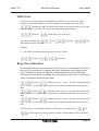
Busy tone detection
The Doortello Business doorphone can detect a busy tine to terminate the call and
the end of a conversation. As default the device can detect three different busy
tones: standard CO busy tone 500/500, standard PBX busy tone 200/400 and
special busy tone 220/220. If needed, you can reprogram the tones. To reprogram
a busy tone please follow this procedure:
OK tone
{make busy tone 1 in ms x 10} OK tone {break busy
tone 1 in ms x 10} OK tone {No. of busy tone to be detected before hang up} OK
tone
OK one
{make busy tone 2 in ms x 10} OK tone {break busy
tone 2 in ms x 10} OK tone {No. of busy tone to be detected before hang up} OK
tone
OK tone
{make busy tone 3 in ms x 10} OK tone {break busy
tone 3 in ms x 10} OK tone {No. of busy tone to be detected before hang up} OK
tone
For the make (tone duration) and the break (tone pause) values from
to
can be inserted. For the number of tone to detect before call termination
Page 34
Issue 1.02
values from
Doortello Business
to
User guide
can be programmed.
Example:
You have to program te detection of a busy tone with a make of 200 ms (20 x
10) and a break of 200 ms, the call has to be terminated after the detection of min.
three tones. Input
n
OK tone
OK tone
OK tone
OK tone
Please note!
The number of tone to be detected before terminating the call should not
have a too small value. If this is the case it might be that the device can
detect normal speech as a busy tone and truncate the call. We suggest to not
use values below 3.
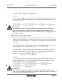
Ring back tone detection
The Doortello Business can count the numbers of rings sent to the called party by
detecting the ring back tone. As default the ring back tone detected is the standard
1000 make and 4000 break tone. If needed you can change this tone following this
procedure:
OK tone
{make 1 in ms x 10} OK tone {break 1 in ms x 10}
OK tone {make 2 in ms x 10} OK tone {break 2 in ms x 10} OK tone
The make values 1 and 2 (duration of the tone) and the break value 1 (pause of
the tone) can be between
be between
and
and
, the break value 2 can
.
Example:
You want to detect a double ring back tone with a make of 250 ms (25 x 10),
a break of 500 ms (50 x 10), a second make of 250 ms (20 x 10) and a second
break of 4000 ms (400 x 10) duration. Input:
n
OK tone
OK tone
OK tone
OK tone
OK tone
Please note!
If you want to program a ring back tone with a single make and break you
have to use only the values make 1 and break 2. The values break 1 and make 2
have to have in this case a value of 000.
Page 35
Issue 1.02
Doortello Business
User guide
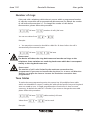
Number of rings
If the unit calls a telephone which doesn’t answer within a programmed number
of calls the connection will be automatically disconnected. As default the number
of call before disconnection is 7. To change the number of calls before
disconnection, please follow this procedure:
OK tone
You can use values from
{number of calls} OK tone
to
.
Example:
You want that a extension should be called for 18 times before the call is
automatically disconnected: Input:
n
OK tone
OK tone
Please note!
The device will detect the ring back tones and not the real rings to the
telephone. Some switches can send ring back tones which don’t correspond
exactly to the ring back tones sent.
Please note!
The number of call is also limited by the maximum connection time
programmed. If you want to increase the ring time (i.e. to use a call diversion
feature) you might also have to increase the maximum connection time
programmed.
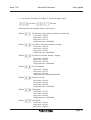
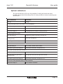
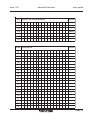
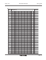
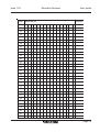
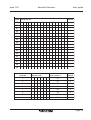
Tone tables
To make the tone programming easier the system has 30 predefined tone table
which can beloaded on request. Loading the table all the specific busy and ring back
tone are setted at once. A single programmation of each tone is then no more
necessary. As default the table 01 is loaded. If you want to change the tone table
please follow this procedure:
OK tone
Values from
to
{table number} OK tone
can be used.
Example:
Page 36
Issue 1.02
n
Doortello Business
User guide
You want to load the tone table 11 (Panasonic PBX). Input:
OK tone
OK tone
Follwing table are available today in the system:
Tabelle
CO Germany, Italy, Norway, Mexico, Luxembourg
Busy tone 1: 50/50
Busy tone 2: 25/25
Busy tone 3: 22/22
Ring back tone: 1000/4000
Tabelle
CO Sveden, Denmark, Iceland, Portugal
Busy tone 1: 25/25
Busy tone 2: 50/50
Busy tone 3: 20/40
Ring back tone: 1000/5000
Tabelle
CO Austria, Finnland, Greece, Hungary
Busy tone 1: 30/30
Busy tone 2: 20/20
Busy tone 3: 50/50
Ring back tone: 1000/5000
Tabelle
CO UK, Australia
Busy tone 1: 38/38
Busy tone 2: 35/25
Busy tone 3: 50/50
Ring back tone: 400/200/400/2000
Tabelle
CO Spain, France
Busy tone 1: 20/20
Busy tone 2: 50/50
Busy tone 3: 00/00
Ring back tone: 1500/3200
Tabelle
COSingapur
Busy tone 1: 75/75
Busy tone 2: 50/50
Busy tone 3: 20/40
Ring back tone: 1000/4000
Tabelle
CO Belgium
Busy tone 1: 50/50
Busy tone 2: 20/20
Busy tone 3: 00/00
Page 37
Issue 1.02
Doortello Business
User guide
Ring back tone: 1000/3000
Tabelle
CO Cech Republik
Busy tone 1: 33/33
Busy tone 2: 16/16
Busy tone 3: 00/00
Ring back tone: 1000/4000
Tabelle
CO USA, Canada, Ireland, Turkey
Busy tone 1: 50/50
Busy tone 2: 25/25
Busy tone 3: 20/20
Ring back tone: 2000/4000
Tabelle
Agfeo PBX
Busy tone 1: 20/40
Busy tone 2: 50/50
Busy tone 3: 00/00
Ring back tone: 400/2000
Tabelle
Panasonic PBX
Busy tone 1: 20/20
Busy tone 2: 25/25
Busy tone 3: 10/10
Ring back tone: 500/300/500/2800
Tabelle
Siemens PBX
Busy tone 1: 53/53
Busy tone 2: 16/44
Busy tone 3: 00/00
Ring back tone: 1000/4000
Tabelle
T-Com PBX
Busy tone 1: 25/25
Busy tone 2: 50/50
Busy tone 3: 00/00
Ring back tone: 1000/4000
Tabelle
Avaya PBX
Busy tone 1: 16/48
Busy tone 2: 50/50
Busy tone 3: 00/00
Ring back tone: 1000/4000
Tabelle
Auerswald PBX
Busy tone 1: 23/23
Busy tone 2: 50/50
Busy tone 3: 00/00
Page 38
Issue 1.02
Doortello Business
User guide
Ring back tone:1000/4000
Tabelle
Gesko PBX
Busy tone 1: 50/50
Busy tone 2: 00/00
Busy tone 3: 00/00
Ring back tone: 500/2000
Please note!
All other table are empty.
Page 39
Issue 1.02
Doortello Business
User guide
How to use
The following use description is based on the default functionality. The described
procedure may change if the device has been reprogrammed.
Calling a phone using a chime button
Press the chime button at the doorstation. The red LED (is installed) will light up and
the stored number will be dialled. When the called party answers the call the red
LED will go off and the green LED (if installed) will light up. You can now talk to the
called party.
Calling a phone using the dial pad
Press the button „handset“ at the doorstation. The red LED will light up and a dial
tone can be heard on the loudspeaker. Now you can dial the desired telephone
number using the dial pad. The single DTMF digits can be heard on the
loudspeaker. With each key pressed the green LED will acknowledge this with a
short flash. If needed, i.e. if you are using the device connected to a GSM, DECT or
VoIP adapter, you can terminate the dialling by pressing the digit
.
If you press a wrong digit you can reset the connection by pressing the "handset"
button again. The connection will be now terminated a set up again with a new dial
tone. When the called party will asnwer the call the red LED will go off a the green
LED will light up. You can talk now with you correspondent.
Please note!
The input on the dial pad is time restricted. After the line seizure, and after
each following button activation, you will have 5 s time to press the next
button. After timeout the dial pad will be deactivated and you have to wait for
the maximum line seizure timeout before making a new dial.
Please note!
The automatic connection termination and new seizure after a wrong dial will
work only with devices with an EXTERNAL POWER SUPPLY. Units which are
powered only using the telephone line can terminate the call and have to seize
the line pressing the "handset" button again.
Calling a phone using a speed dial
Press the button „handset“ at the doorstation. The red LED will light up and a dial
tone can be heard on the loudspeaker. Now you can dial a speed dial code
between
and
using the dial pad. With each key pressed the
green LED will acknowledge this with a short flash. If the code is correct a number
will be dialled on the line. You will hear the DTMF digits. If the code is wrong the
connection will be terminated.
If you press a wrong digit you can reset the connection by pressing the „handset“
button again. The connection will now be terminated a set up again with a new
Page 40
Issue 1.02
Doortello Business
User guide
dial tone. When the called party will answer the call the red LED will go off a the
green LED will light up. You can talk now with you correspondent.
Please note!
The input on the dial pad is time restricted. After the line seizure, and after
each following button activation, you will have 5 s time to press the next
button. After timeout the dial pad will be deactivated and you have to wait for
the maximum line seizure timeout before making a new dial.
Please note!
The automatic connection termination and new seizure after a wrong dial will
work only with devices with an EXTERNAL POWER SUPPLY. Units which are
powered only using the telephone line can terminate the call and have to seize
the line pressing the "handset" button again.
Access code
Press the button „key“ at the doorstation. The red LED will light up. Now you can
dial am access code using the dial pad. With each key pressed the green LED will
acknowledge this with a short flash. The code input has to be terminated with the
button. If the code is correct the red LED will go off, the green LED will light
up and the specific driver contact will be activated for the duration of 5 s. If the
code is wrong the connection will be terminated and seized again for a new input
until a right code has been netered or the maximum line seizure timeout is
reached.
If you press a wrong digit you can reset the connection by pressing the „key“
button again. The connection will now be terminated a set up again.
Please note!
The input on the dial pad is time restricted. After the line seizure, and after
each following button activation, you will have 5 s time to press the next
button. After timeout the dial pad will be deactivated and you have to wait for
the maximum line seizure timeout before making a new dial.
Please note!
The automatic connection termination and new seizure after a wrong dial will
work only with devices with an EXTERNAL POWER SUPPLY. Units which are
powered only using the telephone line can terminate the call and have to seize
the line pressing the "handset" button again.
Direct activation of a driver contact
If needed it is possible to activate a driver contact by pressing directly a therefore
programmed button (i.e. the „lamp“ button on the dial pad or a chime button). In
this case the associated driver contact will be activated for 5 s after pressing the
button. The green LED (is installed) will light up for the duration of the activation.
Page 41
Issue 1.02
Doortello Business
User guide
Incoming call to the doorphone
The doorphone can be called any time. The call will be answered automatically.
After the call answer you can speak to the visitor or start the programming mode
using a password.
Please note!
The programming mode can be activated only within 5 s after call answer.
Please note!
The automatic call answer can be deactivated only using device with
EXTERNAL POWER SUPPLY. In this cases an incoming call is indicated by a
flashing red LED (if installed). The call can be answered by pressing one of the
functional or chime buttons.
Call termination
The call will be terminated if:
- The called party will not answer the call within 7 rings;
- The called party is busy;
- The called party dial a driver contact activation code;
- The called party dial the digit
to terminate the call;
- The called party hangs up and a busy tone is recognized;
- The maximum line seizure timeout is reached.
Code digits for the phones
Page 42
Issue 1.02
Doortello Business
User guide
Optical indicators
The optical indicators (LED) are only available if a dial pad module has been
installed. Using external encoding units it is also possible to connect external green
and red LED.
Type of indication
Information
Both off
Standby
During intialisation (after power failure or frist installation)
Red LED steady on
Line seiz ure and testing, measurement of noise level
Red and green LED steady on
Processor are synchroniz ed
Green LED steady on
Data/d efault dat are loaded in working memory
During programming mod us
Red LED steady on
Programming mod us activated , p assword OK
Red LED steady on, green LED is
flashing shortly
DTMF tone recongniz ed
Red and green LED steady on
Data are stored on the flash RAM
After chime button activation
Red LED steady on
Line is seiz ed , numb er will be dialed
Red LED off, green LED steady on
Call has been answered , microphone is on
After dial or speed dial button activation
Red LED steady on
Line is seiz ed , ready to dial
Red LED steady on, green LED is
flashing shortly
Dial digit has been pressed , digit will be dialed
Red LED off, green LED steady on
Call has been answered , microphone is on
After access code input/direct driver contatct activation
Green LED steady on
Driver contact is activated
Page 43
Issue 1.02
Doortello Business
User guide
Trouble shooting
The door phone can not be programmed
1. Check if you are using the right password.
2. Check if the automatic answer feature was deactivated. In this case you have to
answer the call manually at the door phone.
3. The DTMF tones your system is sending may have a too high level. Try to
program the device using an incoming external call.
The door phone does not dial
1. Check if a telephone line is connected to the device.
2. Check if the the telephone line has a open circuit voltage between 20 and 60 V
dc.
3. May be that the initialisation procedure was not correctly completed. Please call
again the door phone, wait for a busy tone and try then again.
4. Check if the chime button you are using is programmed and has the correct
address.
After connecting the telephone line the device will size the line all the time
1. Disconnect the DB bus connector on the unit, may be that one of the chime
buttons has a short circuit.
2. Check if the the telephone line has a open circuit voltage between 20 and 60 V
dc.
3. Disconnect and reconnect the telephone line and the external power supply if
installed. Make a new initialisation of the device.
After a telephone connection a loud feedback tone is heard at the door
phone
1. Check volume of loudspeaker and microphone.
2. Check if you are using the full or half duplex feature. If you have a feedback you
have to use the half duplex functionality.
3. If you have a behind panel installation check that the device is correctly
installed. The microphone and loudspeaker have to be in contact with the front
plate.
4. Check that the microphone is in aligned with a hole to the outside. If necessary
you can extract the microphone from the housing and install it otherwise.
The door opener will not be activated
1. Check if the door opener has a adequate power supply. The contact in the door
phone is a dry contact and doesn’t have power to supply the door opener. Try to
short circuit the screw contacts to see if the door opener works correctly.
2. Check if the driver contact is supplied with min. 6 Vac/dc. If the voltage is below
this value (i.e. TTL driver) the driver contact doesn’t work. In this case you have to
use an external relay or the DB RU 1 unit.
3. Check is the driver contact is correctly programmed.
4. The driver contact can be activated only after a call answer and speech
detection (green LED and microphone must be on).
Page 44
Issue 1.02
Doortello Business
User guide
The loudspeaker has a „hopping“ volume
1. The volume of the loudspeaker is automatically regulated with the line current.
If the loudspeaker volume is regulated too high, the telephone line might not have
enough power to supply the device at high volume. To avoid this reduce the
volume or try to power the device with an external power supply.
Technical support
Use the telephone number or e-Mail address on the last page of this manual for
more information.
Page 45
Issue 1.02
Doortello Business
User guide
Technical data
Power supply:
The telephone line should not have a open circuit voltage below 20 Vdc.
If it is lower an external power supply unit has to be used.
External power supply: 8 to 12 Vdc (MAXIMUM), max. 400 mA
Power consumption on
telephone line:
ca. 15 µA (standby)
18-60 mA (nominal)
Optical indicators:
One green and one red LED (only using key pad module)
Speakerphone:
Speech driven half-duplex speakerphone, full-duplex speakerphone,
manual switching speakerphone
Dial:
DTMF
DTMF tone detection: min. 50 ms duration
Busy tone detection: 350 - 480 Hz fully programmable
Ring back tone
detection:
350 - 480 Hz fuly programmable
Line impedance:
600 Ohm or Zr selectable
Programming:
using a phone and DTMF tones
Call answer:
automatic or manual (programmable)
Ring voltage detection: 24 to 90 Vac (with or without dc voltage superimposion), 25 to 50 Hz
Integrated driver contact
power:
40 V ac/dc, 2 A max.
Casing:
ABS case and 2 mm 316L (V2A) stainless steel panel (ES version only)
Protection degree:
IP 55 (ES version)
Dimensions HxLxD:
94 x 86 x 22 mm (BG)
100 x 92 x 25 mm (ES)
Weight:
100g (BG)
350g (ES)
Working temperature: -20° bis +50°C (with external power supply)
Humidity:
30 to 90% relative humidity without condensing
Security:
EN 60950, 2006/95/CE
EMC:
EN 55022:2006; EN 61000-6-1:2002, 2004/108/CEE
Telecom:
ETSI EN 301 437; TBR 21
Approvals:
R&TTE, CE
Further norms
compliance:
WEEE, RoHS
Page 46
Issue 1.02
Doortello Business
User guide
Programming codes overview
Following an overview of all the programming code used to configure the Doortello
Business unit. In the right column (DEFAULT) you can read the information about the
factory default data programmed for the related code. (T: you will hear a tone).
# Programming code
Function
1.
T<PW>T
Programming mode activation
1234
2.
T
Factory d efault data load
1234
<PW>T
T<tel.no./func./feat.>
3.
<botton>T
<botton>T
Telephon no., functions and features
of the buttons
Delete telephon no., functions and
features
D EFAULT
see list
4.
T
5.
T<tel.no.>
6.
T
<code>T
Delete speed .dial no.
-
7.
T
<1 on,0 off>T
Automatic call answer
1
8.
T
<value>T
Loudspeaker status at line siz e
1
9.
T
<value>T
Micorphone status at line siz e
3
10.
T
<1 on,0 off>T
Automatic disconnection after door
opening
1
11.
T
<1 HD,0 FD>T
Speakerphone mod us
1
12.
T
<value>T
Max. digits input form key pad
T
<PW>
<code>TSpeed dial no.
13.
Password programming
-
32
1234
<PW>T
T
<code no.>
14.
Access code programming
-
Delete access code
-
<code><contact>T
T
15.
<code no.>
<contact>T
Page 47
Issue 1.02
Doortello Business
# Programming code
T
Function
User guide
DEFAULT
<code>
16.
Contacts activation codes
7, 8
60 s
<contact>T
17.
T
<time>T
Max. line seiz ure time
18.
T
<time>T
Dial pause time
2s
19.
T
<time>T
Interdigit time
150 ms
T
<time>
20.
Contacts activation time
5s
<contact>T
21.
T
<time>T
Keyad activation time
5s
22.
T
<time>T
Keypad blocking time
-
23.
T
<time>T
Blocking time increase
-
T
<value>
Max. no. of attempts
-
24.
<call forward. 0 off, 1 on>T
25.
T
<time>T
T
<tone 1,2,3>
26. <make>T<break>T<count>T
Flash signal time
80 ms
Busy tone detection
see
descr.
Ring back tone detection
see
descr.
T
27. <make1>T<break1>T<make2>T
<break2>T
28.
T
<count>T
Max. no.of calls
7
29.
T
<table>T
Tone table load
01
Page 48
Issue 1.02
Doortello Business
User guide
Overview of programmed values
Key
Telephon no./function/feature
D efault
001
-
002
-
003
-
004
-
005
-
006
-
007
-
008
-
009
-
010
-
011
-
012
-
013
-
014
-
015
-
016
-
017
-
018
-
019
-
020
-
021
-
022
-
023
-
024
-
025
-
026
-
027
-
028
-
029
-
030
-
031
-
Page 49
Issue 1.02
Key
Doortello Business
Telephon no./function/feature
User guide
D efault
032
-
033
-
034
-
035
-
036
-
037
-
038
-
039
-
040
-
041
-
042
-
043
-
044
-
045
-
046
-
047
-
048
-
049
-
050
-
051
-
052
-
053
-
054
-
055
-
056
-
057
-
058
-
059
-
060
-
061
-
062
-
Page 50
Issue 1.02
Key
Doortello Business
Telephon no./function/feature
User guide
D efault
063
-
064
-
065
-
066
-
067
-
068
-
069
-
070
-
071
-
072
-
073
-
074
-
075
-
076
-
077
-
078
-
079
-
080
-
081
-
082
-
083
-
084
-
085
-
086
-
087
-
088
-
089
-
090
-
091
-
092
-
093
-
Page 51
Issue 1.02
Key
Doortello Business
Telephon no./function/feature
User guide
D efault
094
-
095
-
096
-
097
-
098
-
099
-
100
-
101
-
102
-
103
-
104
-
105
-
106
-
107
-
108
-
109
-
110
-
111
-
112
-
113
-
114
-
115
-
116
-
117
-
118
-
119
-
120
-
121
-
122
-
123
-
124
-
Page 52
Issue 1.02
Key
Doortello Business
Telephon no./function/feature
User guide
D efault
125
-
126
-
127
-
128
##6#1
129
##6#3
130
-
131
-
Code Speed dial no.
D efault
00
-
01
-
02
-
03
-
04
-
05
-
06
-
07
-
08
-
09
-
10
-
11
-
12
-
13
-
14
-
15
-
16
-
17
-
18
-
19
-
20
-
Page 53
Issue 1.02
Code Speed dial no.
Doortello Business
User guide
D efault
21
-
22
-
23
-
24
-
25
-
26
-
27
-
28
-
29
-
30
-
31
-
32
-
33
-
34
-
35
-
36
-
37
-
38
-
39
-
40
-
41
-
42
-
43
-
44
-
45
-
46
-
47
-
48
-
49
-
50
-
51
-
Page 54
Issue 1.02
Code Speed dial no.
Doortello Business
User guide
D efault
52
-
53
-
54
-
55
-
56
-
57
-
58
-
59
-
60
-
61
-
62
-
63
-
64
-
65
-
66
-
67
-
68
-
69
-
70
-
71
-
72
-
73
-
74
-
75
-
76
-
77
-
78
-
79
-
80
-
81
-
82
-
Page 55
Issue 1.02
Doortello Business
User guide
Code Speed dial no.
D efault
83
-
84
-
85
-
86
-
87
-
88
-
89
-
90
-
91
-
92
-
93
-
94
-
95
-
96
-
97
-
98
-
99
-
Code No.
Access code
D river contact
D efault
1
01
0
2
01
0
3
01
0
4
01
0
1
02
0
2
02
0
3
02
0
4
02
0
Page 56
Issue 1.02
Doortello Business
User guide
Options
The following options care availabel for the Doortello Business Doophone:
Expansion modules
20-2000-0000
20-2000-0010
20-2000-0011
20-2000-0012
20-2000-0013
20-2000-0014
20-2000-0015
20-2000-0116
20-2000-0216
20-2000-0316
20-2000-0416
20-2000-0117
20-2000-0217
20-2000-0317
20-2000-0417
20-2000-0018
20-2000-0020
20-2000-0021
20-2000-0022
20-2000-0122
20-2000-0023
20-2000-0024
20-6930-1800
20-6930-1830
20-2000-0030
20-2000-0031
20-2000-0032
20-2000-0033
DB 00 Empty speakerphone grid module
DB 10 Spare module
DB 11 chime button module with 1 button, DB bus
DB 12 chime button module with 2 buttons, DB bus
DB 13 chime button module with 3 buttons, DB bus
DB 14 chime button module with 4 buttons, DB bus
DB 15 DB bus encoding unit for 4 chime buttons
DB 16 emergency call button module, blue ring illumination, DB bus
DB 16 emergency call button module, red ring illumination, DB bus
DB 16 emergency call button module, green ring illumination, DB bus
DB 16 emergency call button module, yellow ring illumination, DB bus
DB 17 emergency call button module, blue ring illumination, glass cover, DB bus
DB 17 emergency call button module, red ring illumination, glass cover, DB bus
DB 17 emergency call button module, green ring illumination, glass cover, DB bus
DB 17 emergency call button module, yellow ring illumination, glass cover, DB bus
DB 18 empty microphone module
DB 20 dial pad module 12 key + 4 functional button, DB bus
DB 21 information modul with blue illumination, DB Bus
DB 22 empty key lock module
DB 22/1 key lock module with one driver contact
DB 23 empty information module
DB 24 access control transponder receiver unit with 5 cards
Set with 10 slaves card for DB 24
Set with 10 key holder transponder for DB 24
DB 30 b/w camera module coax 1 Vss 75 Ohm output
DB 31 b/w camera module 2 wire symmetrical output
DB 32 colour camera module coax 1 Vss 75 Ohm output
DB 33 colour camera module IP MPEG-4 output
Mounting frame, boxes and pedestals
20-1005-1001
20-1005-1011
20-1005-1002
20-1005-1012
20-1005-1003
20-1005-1013
20-1005-1004
20-1005-1014
20-1005-2001
20-1005-2002
20-1005-2003
20-1005-2004
20-1005-2022
20-1005-2023
20-1005-2024
20-1005-2033
20-1005-2043
20-1005-5001
20-1005-5002
MXXTE1 flush mounting case with anthrazyt frame for 1 module
MXXTE1 flush mounting case with grey frame for 1 module
MXXTE2 flush mounting case with anthrazyt frame for 2 modules
MXXTE2 flush mounting case with grey frame for 2 modules
MXXTE3 flush mounting case with anthrazyt frame for 3 modules
MXXTE3 flush mounting case with grey frame for 3 modules
MXXTE4 flush mounting case with anthrazyt frame for 4 modules
MXXTE4 flush mounting case with grey frame for 4 modules
MXC001 cover frame aluminum for 1 module
MXC002 cover frame aluminum for 2 modules
MXC003 cover frame aluminum for 3 modules
MXC004 cover frame aluminum for 4 modules
MXC202 cover frame aluminum for 4 modules (2+2)
MXC203 cover frame aluminum for 6 modules (3+3)
MXC204 cover frame aluminum for 8 modules (4+4)
MXC303 cover frame aluminum for 9 modules (3+3+3)
MXC303 cover frame aluminum for 12 modules (3+3+3+3)
MXV001 rain shelter stainless steel for 1 module
MXV002 rain shelter stainless steel for 2 modules
Page 57
Issue 1.02
20-1005-5003
20-1005-5004
20-1005-5022
20-1005-5023
20-1005-5024
20-1005-5033
20-1005-5043
20-1005-3001
20-1005-3002
20-1005-3003
20-1005-3004
20-1005-3022
20-1005-3023
20-1005-3024
20-1005-3033
20-1005-3043
20-2000-0710
20-2000-0711
20-2000-0720
20-2000-0721
20-2000-0730
20-2000-0731
20-2000-0740
20-2000-0741
20-2000-0810
20-2000-0811
20-2000-0820
20-2000-0821
20-2000-0830
20-2000-0831
20-2000-0840
20-2000-0841
20-2000-5001
20-2000-5002
20-2000-5003
20-2000-5130
20-2000-5131
20-2000-5132
20-2000-5230
20-2000-5231
20-2000-5232
20-2000-5330
20-2000-5331
20-2000-5332
20-2000-5150
20-2000-5151
20-2000-5152
20-2000-5250
20-2000-5251
20-2000-5252
20-2000-5350
20-2000-5351
20-2000-5352
20-2000-5450
Doortello Business
User guide
MXV003 rain shelter stainless steel for 3 modules
MXV004 rain shelter stainless steel for 4 modules
MXV202 rain shelter stainless steel for 4 modules (2+2)
MXV203 rain shelter stainless steel for 6 modules (3+3)
MXV204 rain shelter stainless steel for 8 modules (4+4)
MXV303 rain shelter stainless steel for 9 modules (3+3+3)
MXV403 rain shelter stainless steel for 12 modules (3+3+3+3)
MXP001 wall mounting case with rain shelter, stainless steel, for 1 MXXTE1
MXP002 wall mounting case with rain shelter, stainless steel, for 1 MXXTE2
MXP003 wall mounting case with rain shelter, stainless steel, for 1 MXXTE3
MXP004 wall mounting case with rain shelter, stainless steel, for 1 MXXTE4
MXP202 wall mounting case with rain shelter, stainless steel, for 2 MXXTE2
MXP203 wall mounting case with rain shelter, stainless steel, for 2 MXXTE3
MXP204 wall mounting case with rain shelter, stainless steel, for 2 MXXTE4
MXP303 wall mounting case with rain shelter, stainless steel, for 3 MXXTE3
MXP403 wall mounting case with rain shelter, stainless steel, for 4 MXXTE3
DB 710 flat wall mounting case, anthrazyt, for 1 module
DB 711 flat wall mounting case, grey, for 1 module
DB 720 flat wall mounting case, anthrazyt, for 2 modules
DB 721 flat wall mounting case, grey, for 2 modules
DB 730 flat wall mounting case, anthrazyt, for 3 modules
DB 731 flat wall mounting case, grey, for 3 modules
DB 740 flat wall mounting case, anthrazyt, for 4 modules
DB 741 flat wall mounting case, grey, for 4 modules
DB 810 adapter fram for deep modules, anthrazyt, for 1 module
DB 811 adapter fram for deep modules, grey, for 1 module
DB 820 adapter fram for deep modules, anthrazyt, for 2 modules
DB 821 adapter fram for deep modules, grey, for 2 modules
DB 830 adapter fram for deep modules, anthrazyt, for 3 modules
DB 831 adapter fram for deep modules, grey, for 3 modules
DB 840 adapter fram for deep modules, anthrazyt, for 4 modules
DB 841 adapter fram for deep modules, grey, for 4 modules
DB 5001 adapter frame white for foreign installations
DB 5002 adapter frame grey for foreign installations
DB 5003 adapter frame black for foreign installations
DB 5130 pedastal flat 1170 mm hight, antharzyt, for 1 module
DB 5131 pedastal flat 1170 mm hight, grey, for 1 module
DB 5132 pedastal flat 1170 mm hight, steel similar surface treatment, for 1 module
DB 5230 pedastal flat 1170 mm hight, antharzyt, for 2 modules
DB 5231 pedastal flat 1170 mm hight, grey, for 2 modules
DB 5232 pedastal flat 1170 mm hight, steel similar surface treatment, for 2 modules
DB 5330 pedastal flat 1170 mm hight, antharzyt, for 3 modules
DB 5331 pedastal flat 1170 mm hight, grey, for 3 modules
DB 5332 pedastal flat 1170 mm hight, steel similar surface treatment, for 3 modules
DB 5150 pedastal flat 1500 mm hight, antharzyt, for 1 module
DB 5151 pedastal flat 1500 mm hight, grey, for 1 module
DB 5152 pedastal flat 1500 mm hight, steel similar surface treatment, for 1 module
DB 5250 pedastal flat 1500 mm hight, antharzyt, for 2 modules
DB 5251 pedastal flat 1500 mm hight, grey, for 2 modules
DB 5252 pedastal flat 1500 mm hight, steel similar surface treatment, for 2 modules
DB 5350 pedastal flat 1500 mm hight, antharzyt, for 3 modules
DB 5351 pedastal flat 1500 mm hight, grey, for 3 modules
DB 5352 pedastal flat 1500 mm hight, steel similar surface treatment, for 3 modules
DB 5450 pedastal flat 1500 mm hight, antharzyt, for 4 modules
Page 58
Issue 1.02
20-2000-5451
20-2000-5452
20-2000-5270
20-2000-5271
20-2000-5272
20-2000-5370
20-2000-5371
20-2000-5372
20-2000-5470
20-2000-5471
20-2000-5472
Doortello Business
User guide
DB 5451 pedastal flat 1500 mm hight, grey, for 4 modules
DB 5452 pedastal flat 1500 mm hight, steel similar surface treatment, for 4 modules
DB 5270 pedastal flat 1700 mm hight, antharzyt, for 2 modules
DB 5271 pedastal flat 1700 mm hight, grey, for 2 modules
DB 5272 pedastal flat 1700 mm hight, steel similar surface treatment, for 2 modules
DB 5370 pedastal flat 1700 mm hight, antharzyt, for 3 modules
DB 5371 pedastal flat 1700 mm hight, grey, for 3 modules
DB 5372 pedastal flat 1700 mm hight, steel similar surface treatment, for 3 modules
DB 5470 pedastal flat 1700 mm hight, antharzyt, for 4 modules
DB 5471 pedastal flat 1700 mm hight, grey, for 4 modules
DB 5472 pedastal flat 1700 mm hight, steel similar surface treatment, for 4 modules
External device and PSU
20-6913-0100
20-6913-1100
20-6922-0200
20-6923-2800
PRS 210 VDE transformator 12 Vac 15 VA
PRS 231 VDE power supply unit 12 Vdc, 12 Vac, 8 Vdc 18 VA
1281 VDE power supply unit 12 Vac, 21 Vdc 48 VA (for video)
CV 01 coax/2 wire video converter
Spare parts
21-2000-0150
21-2000-0260
21-2000-0340
21-1005-0500
21-2001-0014
21-2001-0020
Paper label for information module DB 21
Transparent cover for information module DB 21
Printed cover for transponder access controller DB 24
Bit torx screws with tool for mounting frame
Encoding PCB with bottons for DB 11 - DB 14
Encoding PCB with bottons for DB 20
This symbol indicates that this electric device has to be collected separatly and not disposed with the
normal home waste. The european union has arranged a collect and recycling system where the
manufacturer are responsible for the disposal of this equipment. This devices has been manufactured
using high-quality and recycleable materials and components. The components used inside the electrical
and electronical items may harm, in case of a wrong disposal, the enviroment and the healthy. Please do
not dispose this device in your home waste. If you are the owner bring the not more used device at the
hazardous waste collecting point nearest to you, or to your dealer where you buy the new device.
- If you are using the device as a professional user please follow the indications of the manufactoring
company.
- If the device is part of a leasing contract or you have hold it on stock, please follow the indications of
your distributor.
Please help us to keep our enviroment healthy! Thank you.
Page 59
©
Doortello Business
User guide
Your dealer:
Printed in Germany.
2008 ROCOM GmbH. Product may change without notice. We do not respond for any errors or mistake in the present documentation.
Issue 1.02
Energie- und Kommunikationssysteme GmbH
Lessing Str. 20, 63110 Rodgau, Deutschland
Tel. +49- (0) 6106 - 6600-0 Fax +49-(0) 6106 - 6600-66
HOTLINE +49-(0)6106-646041
E-Mail: [email protected]
http://www.rocom-gmbh.de
Page 60