1
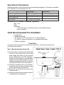
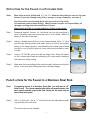
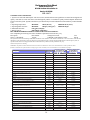
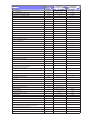
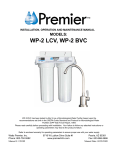
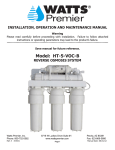
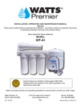
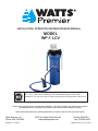
INSTALLATION, OPERATION AND MAINTENANCE MANUAL
MODEL
WP-1 LCV
WP-1 LCV Tested and certified by NSF International against NSF/ANSI
Standard 53 for the reduction of claims specified on the performance data sheet.
Please read carefully before proceeding with installation. Your failure to follow any attached instructions or
operating parameters may lead to the product’s failure and possible damage to property.
Refer to enclosed warranty for operating parameters to ensure proper use with your water supply.
Watts Premier, Inc.
Phone: 800-752-5582
Manual #: 199362
8716 W Ludlow Drive Suite #1 www.wattspremier.com
Peoria, AZ 85381
Fax: 623-866-5666
Manual Date: 05/18/2012
Thank you for your purchase of a state of the art
Watts Premier Water Treatment system.
WP-1 LCV Water Treatment System:
Watts Premier WP-1 LCV water treatment system contains a heavy duty lead, cyst
and VOC filter block. This specialty formulated block is capable of reducing lead,
cryptosporidium, Giardia, Entamoeba as well as harmful Volatile Organic Chemicals
(See performance data sheet for complete list of VOC’s). It is estimated that VOC’s are
present in one-fifth of the nation’s water supplies. These water contaminants can enter
ground water from a variety of sources including localized use of herbicides and pesticides,
gasoline or oil spills, leaking underground fuel tanks, septic system cleaners, and chemicals
used in the dry-cleaning industry. See performance data sheet for individual contaminants
and reduction performance.
System Maintenance
Just because you can not taste it, does not mean that it is not there. Many contaminants in
the drinking water are undetectable to the taste. Additionally, over time if you do not replace
the filter element, other bad tastes and odors will be apparent in your drinking water. This
is why it is important to change out your filter at the recommended intervals as indicated in
this system manual. When replacing any of the filter elements, pay special attention to any
cleaning instructions. Should you have any further questions please refer to our website at
www.wattspremier.com or call our customer service dept. at 1-800-752-5582.
2
Table of Contents
Maintenance Record..................................................................................................... 3
Operational Parameters ............................................................................................... 4
Contents of WP-1 System .............................................................................................4
Tools Recommended For Installation ........................................................................... 4
Under Sink Mounting..................................................................................................... 4
Drill a Hole for the Faucet in a Porcelain Sink................................................................5
Punch a Hole for the Faucet in a Stainless Steel Sink.................................................. 5
Installation of Faucet..................................................................................................... 6
Adapt-a-Valve Installation...............................................................................................7
Start Up......................................................................................................................... 7
Filter Change................................................................................................................. 8
Parts Listing .................................................................................................................. 9
Performance Data Sheet .............................................................................................. 10-11
California Certificates .....................................................................................................12
Removing Chlorine from your Shower........................................................................... 13
Warranty ....................................................................................................................... 14
Maintenance Record
Date of Purchase:__________ Date of Install:_________ Installed by:____________
NOTES:
________________________________________________________________________
________________________________________________________________________
________________________________________________________________________
________________________________________________________________________
________________________________________________________________________
________________________________________________________________________
________________________________________________________________________
________________________________________________________________________
________________________________________________________________________
________________________________________________________________________
________________________________________________________________________
________________________________________________________________________
________________________________________________________________________
________________________________________________________________________
3
Operational Parameters
Installation needs to comply with state and local plumbing regulations. This system is intended
to be installed on the cold supply line only.
Operational Temperature
Operating Pressure
pH Parameters
Flow Rate
Maximum
100°F (37.8°C)
100 psig (7.43 g/cm²)
10
0.5 GPM @ 60 psig
Minimum
40°F (4.4°C)
20 psig (1.406 kg/cm²)
5
Contents of Under Counter System
1 WP-1 Unit
1 Filter
1 Parts Bag
If any of the items are missing, please contact Watts Premier
prior to installing
Tools Recommended For Installation
√ A small knife
√ Variable Speed drill
√ 1/8” (3mm), 1/4” (6.4 mm) and 7/16” (11.0mm) Drill bits
√ 1/2” and 5/8” open-end wrenches (or adjustable Wrenches)
√ Phillips screwdriver
Installation
This system has been designed to fit under most kitchen sinks. Please read carefully before
proceeding with installation.
Step 1: Mounting System Under Sink
(a) Locate a space under the sink that allows
the
unit to be mounted close to the cold
water supply and allows for easy access
during maintenance and filter changes.
System must be installed to the cold water
supply only. Allow approximately 2” (5cm)
clearance between the bottom of the filter
housing and the floor of the sink cabinet.
(c)Using the mounting hole on the bracket,
mark the location for the mounting screws
on the cabinet wall under the sink.
(d)Screw the (2) screws into the wall at the
marked location.
(e)Hang the module on the screws using the
mounting holes in the bracket.
4
Drill a Hole for the Faucet in a Porcelain Sink
Note:
Most sinks are pre drilled with 1 ½” or 1 ¼” diameter hole that you can use for your
faucet. (If you are already using it for a sprayer or soap dispenser, see step 1)
Porcelain sinks are extremely hard and can crack or chip easily.
Use extreme caution when drilling. Watts Premier accepts no responsibility for
damage resulting from the installation of faucet.
Diamond tip drill bit is recommended for drilling in porcelain.
Step 1
Determine desired location for the faucet on your sink and place a
piece of masking tape over where the hole is to be drilled. Mark the
center of the hole on the tape.
Step 2
Using a variable speed drill set on the slowest speed, drill a 1/8“ pilot
hole through both porcelain and metal casing of sink at the marked
center of the desired location. Use lubricating oil or liquid soap to keep
the drill bit cool (If drill bit gets hot it may cause the porcelain to crack
or chip).
Step 3
Using a 1/2” Drill Bit, proceed to drill the larger hole. Keep drill speed
on the slowest speed and use lubricating oil or liquid soap to keep the
hole saw cool during cutting.
Step 4
Make sure the surroundings of the sink are cooled before mounting the
faucet to the sink after drilling and remove all sharp edges.
Punch a Hole for the Faucet in a Stainless Steel Sink
Note:
If mounting faucet to a Stainless Steel Sink you will need a 1/2”
Hole Punch. The faucet opening should be centered between the
back splash and the edge of the sink, ideally on the same side as
the vertical drain pipe.
Step 5
Drill a ¼” pilot hole. Use a 1/2” Hole Punch and an adjustable wrench
to punch the hole in the sink.
The faucet can now be installed.
5
Installation of Faucet
Step 1
Step 2 Place the escutcheon chrome plate and the black rubber washer on the
faucet shank. (Parts found in faucet parts bag).
Insert the faucet shank through the hole in sink and let it rest on the sink top.
Step 3 From the underside of the sink, slide on the locating washer, lock washer and brass nut onto the shank. Check orientation of faucet then tighten brass nut securely.
Step 4
Connect blue tube from the filtration system to the faucet shank.
Place the brass nut onto the tube, followed by the plastic sleeve (tapered
end pointing to the end of tube) and then place the plastic insert into the end of the tube.
Step 5
Insert the assembled blue tube into the end of the faucet shank and use a
wrench to tighten the brass nut securely.
6
Adapt-a-Valve Installation
Caution: Water supply line to the system must be from the cold water supply line. Hot water will severely damage your system.
(A)Turn off the main supply water to the house.
(B) Turn off the cold water supply to the faucet by turning the angle stop valve clockwise
until it is completely off. Drain any water in the line by opening the faucet cold side.
(C) Attach adapt-a-valve as illustrated in the center photo below, choosing the configuration
that fits your plumbing.
(D) Attach the loose end of the green tube to the Adapt-a-Valve.
Insert the green tube into the ¼” opening on the adapt-a-valve until it stops.
(E) Turn on water supply and open the Adapt-a-valve. Check for leaks.
Configuration:
* Washer
Configuration for 3/8”
(With Brass Fittings)
* Insert White Washer
Hot
Supply
Cold
Supply
Configuration for 1/2” (Without Brass Fittings)
System Start Up
(A)Turn faucet handle to the open position to start the flow of water through the unit. Run 7
gallons of water through the unit in order to flush out the normal black carbon fines (it will
“sputter” until the air is purged out) from the unit. Initially, the water may appear cloudy
which is due to tiny air bubbles and it will clear up shortly. Close the faucet when finished.
(B) Check for leaks. If you have any leaks, shut off the water supply to your system, tighten
any fittings / housings and restart unit.
7
FILTER CHANGE
Watts Premier recommends changing the filter element
every 6 months.
Use Watts Premier’s replacement cartridge only. Other
filters may look the same, but only filters by Watts are
manfactured to fit your WP-1 filter unit in order to ensure
proper reduction of water contaminants.
Carbon Block Filter
WP-1 LCV
Figure D
Part# 101014
(a)Turn off incoming water supply to the WP-1 at the adapta-valve. Note: There will be water in the filter housing.
Lift the faucet handle to relieve the water pressure.
(b)Remove filter housing from lid by turning it to the left,
as shown in Figure D.
(c)Remove used filter cartridge and discard.
NOTE: Do not discard filter-housing o-ring.
(d)Clean inside of filter housing with warm soapy water and
rinse to remove soap
(e)Lubricate o-ring with water-soluble lubricant (i.e. K-Y Jelly
® or Silicone lubricant).
NOTE: Do not use Petroleum based lubricants such as
Vaseline ®.
(f) Seat o-ring in groove in filter housing and insert new filter
cartridges into filter housing.
(g)Screw filter housing onto lid as shown in Figure D.
(h) Turn on water supply to filter unit at the Adapt-a-Valve.
(i) Check system for leaks.
8
To Loosen
To Tighten
5
6
2
6
4
ITEM
1
2
3
4
5
6
7
8
9
10
9
8
7
PART #
101014
113002
113019
113054
116023
122036
560080
140004
140007
QTY
1
1
1
1
1
1
1
1
1
3
9
DESCRIPTION
Lead, Cyst. VOC Carbon Block
Lid
Housing 10” Blue
O-Ring
Faucet - NON-AG
Flow Control Elbow
Adapt-a-Valve
Tubing-1/4” Blue 4FT
Tubing-1/4” Green 4FT
Performance Data Sheet
Watts Premier Inc.
8716 W Ludlow Drive Suite #1
Peoria, AZ 85381
WP-1 LCV
GENERAL USE CONDITIONS:
1: System to be used with municipal or well water sources treated and tested on regular basis to insure bacteriological safe
quality. DO NOT use with water that is microbiologically unsafe or of unknown quality without adequate disinfection
before or after the system. Systems certified for cyst reduction may be used on disinfected waters that may contain filterable
cysts.
2: Operating Temperature:
Maximum
100o F (40.5o C)
Minimum 40o F (4.4o C)
2
3: Operating Water Pressure: Maximum
100-psi (7.43 kg/cm )
Minimum 20-psi
4: Maximum flow Rate:
0.50 gpm (1.89 lpm)
5: Rated Capacity:
600 Gallons (2,200 liters)
RECOMMENDED REPLACEMENT PARTS AND CHANGE INTERVAL:
Note: Depending on incoming feed water conditions replacement time frame may vary.
Description
Part Number
Change time Frame
Cost
Stage 1: Carbonblock 101014
6 Months or 600 gallons of water
$28.95
This system has been tested according to NSF/ANSI Standard 53 for the reduction of the substances listed below. The concentration of the indicated
substances in water entering the system was reduced to a concentration less than or equal to the permissable limit for water leaving the system, as
specified in NSF/ANSI 53. Testing performed under standard laboratory conditions, actual performance may vary.
California Proposition 65 Warning
WARNING: this product contains chemicals known to the State of California to cause cancer and birth defects or other reproductive harm.
(Installer: California law requires that this warning be given to the consumer). For more information: www.wattsind.com/prop65.
Substance
Percent
Reduction
Influent Challenge
Concentration
(mg/L unless noted)
Maximum Permissible
Product Water
Concentration
ALACHLOR*
>98%
0.04 +/- 0.10
0.002
ATRAZINE*
>97%
0.009 +/- 0.10
0.003
BENZENE*
>99%
0.015 +/- 0.10
0.005
BROMODICHLOROMETHANE (TTHM)*
>99.8%
0.300 +/- 0.30
0.015
BROMOFORM (TTHM)*
>99.8%
0.300 +/- 0.30
0.015
CARBOFURAN (Furadan)*
CARBON TETRACHLORIDE*
>99%
0.08 +/- 0.10
0.04
98%
0.015 +/- 0.10
0.005
0.04 +/- 0.10
0.002
CHLORDANE
CHLOROBENZENE (Monochlorobenzene)*
>99%
2.0 +/- 0.10
0.1
CHLOROFORM (TTHM)*
>99.8%
0.300 +/- 0.30
0.015
CRYPTOSPORIDIUM (see Cyst)
99.99%
minimum 50,000/mL
99.95%
CYST
99.99%
minimum 50,000/mL
99.95%
98%
0.210 +/- 0.10
0.07
>99%
0.052
0.00002
95%
0.088
0.0048
>99%
0.083
0.001
2, 4-D*
DBCP (see Dibromochloropropane)*
1,2-DCA (see 1,2-DICHLOROETHANE)*
1,1-DCE (see 1,1-DICHLOROETHYLENE)*
DIBROMOCHLOROMETHANE
(TTHM;Chlorodibromomethane)*
DIBROMOCHLOROPROPANE (DBCP)*
>99.8%
0.300 +/- 0.30
0.015
>99%
0.004 +/- 0.10
0.0002
o-DICHLOROBENZENE (1,2 Dichlorobenzene)*
>99%
1.8 +/- 0.10
0.6
p-DICHLOROBENZENE (para-Dichlorobenzene)*
>98%
0.225 +/- 0.10
0.075
0.005
1,2-DICHLOROETHANE (1,2-DCA)*
95%
0.015 +/- 0.10
1,1-DICHLOROETHYLENE (1,1-DCE)*
>99%
0.021 +/- 0.10
.007
CIS-1,2-DICHLOROETHYLENE*
>99%
1.4 +/- 0.10
0.07
TRANS-1,2- DICHLOROETHYLENE*
>99%
2.0 +/- 0.10
0.1
1,2-DICHLOROPROPANE (Propylene Dichloride)*
>99%
0.015 +/- 0.10
0.005
CIS-1,3- DICHLOROPROPYLENE*
>99%
0.079
0.001
99%
0.021 +/- 0.10
0.007
>99%
0.044
0.00002
99%
0.006 +/- 0.10
0.002
DINOSEB*
EDB (see ETHYLENE DIBROMIDE)*
ENDRIN*
10
Substance
ENTAMOEBA
Percent
Reduction
Influent Challenge
Concentration
(mg/L unless noted)
Maximum Permissible
Product Water
Concentration
99.95%
99.99%
minimum 50,000/mL
ETHYLBENZENE*
>99%
2.1 +/- 0.10
0.7
ETHYLENE DIBROMIDE (EDB)*
>99%
0.001 +/- 0.10
0.00005
FURADAN (see CARBOFURAN)*
>99%
0.19
0.001
BROMOCHLOROACETONITRILE
98%
0.022
0.0005
DIBROMOACETONITRILE
98%
0.024
0.0006
DICHLOROACETONITRILE
98%
0.0096
0.0002
TRICHLOROACETONITRILE
98%
0.015
0.0003
1,1-DICHLORO-2-PROPANONE
99%
0.0072
0.0001
1,1,1-TRICHLORO-2-PROPANONE
96%
0.0082
0.0003
99.99%
minimum 50,000/mL
99.95%
>99%
0.25
0.00001
HALOACETONITRILES (HAN)*
HALOKETONES (HK):*
GIARDIA LAMBLIA (see Cyst)
HEPTACHLOR*
HEPTACHLOR EPOXIDE*
98%
0.0107
0.0002
HEXACHLOROBUTADIENE
(Perchlorobutadiene)*
>98%
0.044
0.001
HEXACHLOROCYCLOPENTADIENE*
>99%
0.060
0.000002
LEAD pH 6.5
99%
0.15 +/- 10%
0.010
LEAD pH 8.5
99%
0.15 +/- 10%
0.010
0.08 +/- 0.10
0.0004
0.004 +/- 0.10
0.0002
HEPTACHLOR (H-34, HEPTOX)
HEPTACHLOR EPOXIDE
HEXACHLOROCYCLOPENTADI
0.15 +/- 0.10
0.05
LINDANE*
>99%
0.002 +/- 0.10
0.0002
METHOXYCHLOR*
>99%
0.12 +/- 0.10
0.04
METHYLBENZENE (see TOLUENE)*
>99%
0.015 +/- 0.20
0.005
MONOCHLOROBENZENE
(see CHLOROBENZENE)*
>99%
0.077
0.001
PCE (see TETRACHLOROETHYLENE)*
>99%
0.081
0.001
PENTACHLOROPHENOL*
>99%
0.01 +/- 0.10
0.001
PERCHLOROBUTADIENE
(see HEXACHLOROBUTADIENE)*
>98%
0.044
0.001
PROPYLENE DICHLORIDE
(see 1,2 -DICHLOROPROPANE)*
>99%
0.080
0.001
0.01 +/- 0.10
0.0005
POLYCHLORINATED BIPHENYLS (PCBs, Aroclor 1260)
SIMAZINE*
>97%
0.012 +/- 0.10
0.004
99%
0.270
0.0016
>99%
2.0 +/- 0.10
0.1
SILVEX (see 2,4,5-TP)*
STYRENE (Vinylbenzene)*
1,1,1-TCA
(see 1,1,1 - TRICHLOROETHANE)*
95%
0.084
0.0046
TCE (see TRICHLOROETHYLENE)*
>99%
0.180
0.0010
1,1,2,2- TETRACHLOROETHANE*
>99%
0.081
0.001
TETRACHLOROETHYLENE*
>99%
0.015 +/- 0.10
0.005
TOLUENE (Methylbenzene)*
>99%
TOXOPLASMA
2,4,5-TP (Silvex)*
99%
TRIBROMOACETIC ACID*
TOXAPHENE
3.0 +/- 0.10
1
minimum 50,000/mL
99.95%
0.15 +/- 0.10
0.05
0.042
0.001
0.015 +/- 0.10
0.003
>99%
0.21 +/- 0.10
0.07
95%
0.6 +/- 0.10
0.2
1,1,2-TRICHLOROETHANE*
>99%
0.015 +/- 0.10
0.005
TRICHLOROETHYLENE (TCE)*
>99%
0.300 +/- 0.10
0.005
1,2,4 TRICHLOROBENZENE (Unsymtrichlorobenzene)*
1,1,1-TRICHLOROETHANE (1,1,1-TCA)*
TRIHALOMETHANES (TTHM) (Chloroform; Bromoform;
Bromodichloromethane; Dibromochloromethane)
>99.8%
0.45 +/- 0.20
0.080
Unsym-Trichlorobenzene (see 1,2,4TRICHLOROBENZENE)*
>99%
0.160
0.0005
Vinylbenzene (see STYRENE)*
>99%
0.150
0.0005
XYLENES
>99%
30 +/- 0.10
10
11
13
11
Removing chlorine from your shower
Special Chlorgon & KDF media – More effective then carbon medias with
hot water applications in the removal of the following.
√
√
√
√
√ Iron oxide (rust water)
Free Chlorine (CL-)
Combined Chlorine (Sodium Hypochlorite) √ Dirt, sediment
√ Odors
Hydrogen Sulfide (Rotten egg smell)
Plus, its pH balanced.
Deluxe Shower Handle with Built in Filter
Replacement filters 2PK
5-Way Massaging Spray
72” Reinforced Hose
High Strength Bracket
Triple Plated Finish
Reversible Filter Cartridge (Model HHC)
Cartridge Life Rating: 3 months
Part No. 107070
WHITE
*$38.95
Part No. 107091
CHROME
*$44.95 Part No. 107075 *$15.95/pk
Part No. 107092
GOLD
*$44.95
Shower Falls Deluxe Shower Handle with Built in Filter
Curved Ergonomic Shower Handle
Replacement filters 2PK
Filter Handle Extension
Dual Swivel Adjustment
Ultra Deluxe 5 Way Massaging Spray
72” Reinforced Hose
Chrome Plated Brass Bracket & Swivel Ball Extension
Triple Plated Finish
Reversible Filter Cartridge (Model HHC)
Cartridge Life Rating: 3 months
Part No. 107095 CHROME *$55.95
Part No. 107075 *$15.95/pk
All-In-One reversible High-Flow Filter
Deluxe 5-Way Massaging Spray
Soft-Touch Adjustment Pads
Anti-Scaling Spray Nozzle
High Strength Housing
Triple Plated Finish
Cartridge Life Rating: 6 months
Part No. 107098 White/Chrome
*$39.95
Replacement filter
Part No. 107080 *$13.95/ea
*All prices subject to change without notice.
12
8716 W Ludlow Drive Suite #1 • Peoria, AZ 85381
Limited Warranty
What your Warranty Covers:
If any part of your WATTS PREMIER WP-1 is defective in workmanship (excluding replaceable filters ), return unit after
obtaining a return authorization (see below), within 3 year of original retail purchase, WATTS PREMIER will repair or, at
WATTS PREMIER’S option, replace the system at no charge.
How to obtain Warranty Service:
For warranty service, call 1-800-752-5582 for a return authorization number. Then, ship your unit to our factory, freight and
insurance prepaid, with proof of date of original purchase. Please include a note stating the problem. Premier will repair it,
or replace it, and ship it back to you prepaid.
What this warranty does not cover:
This warranty does not cover defects resulting from improper installation, (contrary to WATTS PREMIER’S printed
instructions), from abuse, misuse, misapplication, improper maintenance, neglect, alteration, accidents, casualties, fire,
flood, freezing, environmental factors, water pressure spikes or other such acts of God.
This warranty will be void if defects occur due to failure to observe the following conditions:
1. The WP-1 System must be hooked up to a potable municipal or well cold water supply.
2. The pH of the water must not be lower than 5 or higher than 10.
3. The incoming water pressure must be between 20 and 100 pounds per square inch.
4. Incoming water to the Counter Top cannot exceed 100 degrees F (38 degrees C.)
This warranty does not cover any equipment that is relocated from the site of its original installation.
This warranty does not cover any equipment that is installed or used outside the United States of America and Canada.
LIMITATIONS AND EXCLUSIONS:
WATTS PREMIER WILL NOT BE RESPONSIBLE FOR ANY IMPLIED WARRANTIES, INCLUDING THOSE OF MERCHANTIBILITY
AND FITNESS FOR A PARTICULAR PURPOSE. WATTS PREMIER WILL NOT BE RESPONSIBLE FOR ANY INCIDENTAL OR
CONSEQUENTIAL DAMAGES, INCLUDING TRAVEL EXPENSE, TELEPHONE CHARGES, LOSS OF REVENUE, LOSS OF TIME,
INCONVENIENCE, LOSS OF USE OF THE EQUIPMENT, AND DAMAGE CAUSED BY THIS EQUIPMENT AND ITS FAILURE TO
FUNCTION PROPERLY. THIS WARRANTY SETS FORTH ALL OF PREMIER’S RESPONSIBILITIES REGARDING THIS EQUIPMENT.
OTHER CONDITIONS:
If WATTS PREMIER chooses to replace the equipment, WATTS PREMIER may replace it with reconditioned equipment. Parts used in
repairing or replacing the equipment will be warranted for 90 days from the date the equipment is returned to you or for the remainder of
the original warranty period, whichever is longer. This warranty is not assignable or transferable.
YOUR RIGHTS UNDER STATE LAW:
Some states do not allow limitations on how long an implied warranty lasts, and some states do not allow the exclusion or limitation of
incidental or consequential damages, so the above limitations or exclusions may not apply. This warranty gives you specific legal rights,
and you may have other legal rights which vary from state to state.