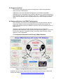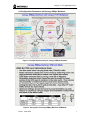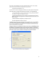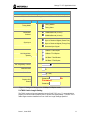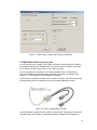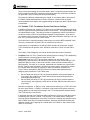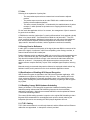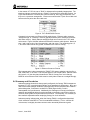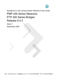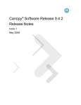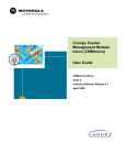
1
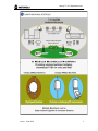
Canopy™ T1/E1
Multiplexer
Application Note
MUX-AN-en
Issue 1
June 2005
Notices
The recommendations in this Application Note and in the Canopy T1/E1 Multiplexer User
Guide give the installer the knowledge to optimize the configuration settings to achieve a
reliable and high performance T1/E1 link.
Please refer to the Canopy System User Guide, posted at www.motorola.com/canopy for:
◦
Personal safety guidelines in Preventing Overexposure to RF Energy
◦
Important regulatory and legal notices
Trademarks, Product Names, and Service Names MOTOROLA and the Stylized M Logo are registered in the US Patent & Trademark
Office. All other product or service names are the property of their respective owners.
© Motorola, Inc. 2005.
http://www.motorola.com/canopy
2
Canopy T1 / E1 Application Note
Issue 1, June 2005
3
Table of Contents
Using This T1/E1 Multiplexer Application Note ............................................................................... 5
Searching This Application Note ..................................................................................................... 5
T1 / E1 Multiplexer Application Note ............................................................................................... 5
1.0 Abstract .................................................................................................................................. 5
2.0 Circuit Emulation over Canopy .............................................................................................. 5
3.0 Purpose and Goal .................................................................................................................. 6
4.0 Optimum Backhaul and TMUX Configuration:....................................................................... 6
4.1 Configuration Parameters with Canopy 20Mbps Backhaul................................................ 6
4.2 Configuration Parameters with Canopy 45Mbps Backhaul................................................ 7
5.0 T1/E1 Multiplexer Configuration Guidelines .......................................................................... 8
5.1 Canopy System Operating Margin ..................................................................................... 8
5.2 Electrical Grounding of the TMUX...................................................................................... 9
5.3 TMUX and Canopy BH20 Ethernet Port Settings .............................................................. 9
5.4 TMUX Cable Length Setting............................................................................................. 11
5.5 TMUX RJ45 to BNC Converter Cable.............................................................................. 12
5.6 “Outside” T1/E1 Termination Device Clock Source Settings ........................................... 13
5.7 Jitter.................................................................................................................................. 14
5.8 Canopy Passive Reflectors .............................................................................................. 14
5.9 Ramifications of Enabling AES Channel Encryption........................................................ 14
5.10 Enabling Canopy BH20 Hardware Scheduling .............................................................. 14
5.11 T1/E1 Cabling................................................................................................................. 14
6.0 Summary and Conclusion.................................................................................................... 15
Additional Resources..................................................................................................................... 16
4
Canopy T1 / E1 Application Note
Using This T1/E1 Multiplexer Application Note
This document should be used with following Canopy™ User Guides*:
-
Canopy 45Mbps Backhaul User Guide
Canopy T1/E1 Multiplexer User Guide
Canopy System User Guide
* Important: Visit the Canopy Support Web Site to download the latest Canopy software and
Canopy User Guides. http://www.canopywireless.com/support_home.php
Searching This Application Note
To search this document, look in
◦
the Table of Contents for the topic.
◦
The Adobe Reader® search capability for keywords that apply.1
◦
Use the page numbers at the bottom of the screen and in the thumbnails. These
match the page numbers in the Table of Contents.
◦
Use the EditÆSearch command (or Ctrl+F) to find a word or phrase.
T1 / E1 Multiplexer Application Note
1.0 Abstract
Circuit emulation is a challenging application for any packet-based infrastructure, and
even more so in a Time Division Duplex (that is, half duplex) operational mode. Canopy
supports, with external adjunct “terminal multiplexers” (TMUXs), the circuit emulation
application. Understanding configuration issues and maintaining realistic expectations is
essential. This guide addresses the configuration issues, outlines the radio conditions
necessary for successful circuit emulation, and sets expectations appropriate to this
demanding task.
2.0 Circuit Emulation over Canopy
Canopy supports circuit emulation via external TMUX devices that are paired at either
end of a backhaul link. Apart from the obvious need to configure the TMUX and the
associated Canopy network elements correctly, the success of the circuit emulation
depends upon how radio conditions impact the circuit emulation application.
Potential applications for the T1/E1 Multiplexer include:
◦
Delivering T1/E1 replacement
◦
Implementation of wireless PBX networking
◦
Establishment of cellular backhaul applications
◦
Providing homeland security backup/emergency voice networks
Each TMUX device converts the constant bit rate circuit into a constant sequence of
packets in a flow. These identically sized packets are launched at a constant time
interval to be transported to the other TMUX across the Canopy “air link”.
1
Reader is a registered trademark of Adobe Systems, Incorporated.
Issue 1, June 2005
5
3.0 Purpose and Goal
This document describes proper setup and configuration of both Canopy backhaul
elements and the TMUX devices.
Additionally this document illustrates the importance of maintaining reasonable
expectations for the demanding circuit emulation application over a packet infrastructure.
Circuit emulation can never be as good as a “real circuit.” Traditional circuit performance
metrics can only approach that of a terrestrial-based circuit from a telephony common
carrier.
4.0 Optimum Backhaul and TMUX Configuration:
Circuit emulation, the process of converting PBX traffic to wireless Ethernet and back,
requires the installer to follow documented best practices learned from various lab
testing, field trials and customer installations to achieve a bit error rate (BER) equal to or
better than 10-6.
This section provides two quick start diagrams with the Canopy configuration
parameters* that must be set in order to achieve an optimum configuration. This section
is followed by “Optimum Configuration Details” that further details using the Canopy
System for T1/E1 replacement.
4.1 Configuration Parameters with Canopy 20Mbps Backhaul
Figure 1: Configuration Summary for Canopy 20Mbps Backhaul
* Important: Visit the Canopy Support Web Site to download the latest Canopy software and
Canopy User Guides. http://www.canopywireless.com/support_home.php
6
Canopy T1 / E1 Application Note
4.2 Configuration Parameters with Canopy 45Mbps Backhaul
Figure 2: Configuration Summary for Canopy 45Mbps Backhaul
Figure 3: Description of Canopy 45Mbps Backhaul TDM Mode
Issue 1, June 2005
7
5.0 T1/E1 Multiplexer Configuration Guidelines
These guidelines apply to the 20Mbps Backhaul configuration.
o
o
o
o
o
o
o
o
o
o
o
The Canopy 20Mbps Backhaul operating margin should be at least 3dB above receiver
sensitivity; this is a received signal strength of better than -76dB.
If Canopy 20Mbps Backhaul AES encryption (Release 7.2) is employed, be aware that
doing so will drop the T1/E1 circuit once every 24 hours for the setup of a new encryption
key.
Enable Canopy 20Mbps Backhaul Hardware Scheduler on both units. (Release 7.2)
Be aware of the difference between RJ45 Ethernet cable and RJ45 T1/E1 cable; these
cable types are not interchangeable.
Ground (earth) the TMUX chassis units.
Set the TMUX Ethernet port configuration to “auto-negotiation on.”
Set the Canopy BH20 Ethernet configuration to 100 Mbps Full Duplex.
Set the TMUX units’ T1/E1 cable lengths appropriately.
If “outside” E1 devices employ 75ohm BNC ports, use a high quality conversion cable to
derive a 120ohm RJ45 E1 equivalent for the TMUX.
Know the T1/E1 device configuration of the “outside” T1/E1 terminations, in particular
whether they are synchronized by Stratum clock or expect synchronization from the
T1/E1 line (See Section 5.6):
o Set the TMUX port facing a T1/E1 device having Stratum clock synchronization
to “loop timing”; this could be one or both TMUXs; these are typically Central
Office devices.
o Set the TMUX port facing a T1/E1 device expecting to receive synchronization to
“recovered timing”; this is typically a CPE device; the other TMUX unit should be
set to “loop timing”.
Always install Canopy’s passive reflectors for better signal strength and interference
rejection.
5.1 Canopy System Operating Margin
A statistic concerning the successful operation of any Canopy system, whether in the
TMUX circuit emulation application context or not, is System Operating Margin (SOM).
By definition SOM is the difference in signal strength received and the receiver’s
sensitivity, expressed in dBm (decibels referenced per 1 milliwatt).
Note that a negative dBm value is a signal less than1mW, and a positive value means a
signal stronger than 1mW. In Figure 4 the -96dBm is extremely weak, and in fact
indicates no received signal at all, the circumstance of the “expand stats” screen capture
shown.
Note the Radio Transmit Gain setting is also shown; this is the power being sent into the
Canopy antenna. All Canopy units produce +23dBm (or 200mW). The integrated
antenna adds 7dB, and if the passive reflector is used it adds 18dB (or 8dB if 2.4GHz).
This implies that a Canopy BH20 unit transmits 23+7+18 or 48dB into “space”. The
intermediate “Free Space Loss” (FSL) is dependent upon frequency and range, and
when subtracted from 48dB (in this example) results in the Radio Power Level value
displayed. Other factors may further reduce actual Radio Power Level.
8
Canopy T1 / E1 Application Note
Figure 4. BH20 RSSI and Jitter Display indicating no signal.
In actual operation the Canopy BH20 unit will display a RSSI value above -79dBm.
Motorola strongly recommends the use of passive reflectors at both ends as their narrow
beam characteristic means less multipath signal and better “rejection” of whatever actual
multipath signal there is.
5.2 Electrical Grounding of the TMUX
As stated in the Canopy T1/E1 Multiplexer User Guide, proper grounding (or “earthing”) is
essential for reliable circuit application. One of the Phillips screws on the back of the
TMUX unit should be loosened and connected to a sufficiently large gauge grounding
wire. This grounding should include any T1/E1 equipment as well, so the T1/E1 electrical
signal may be properly interpreted by the TMUX unit. Use local practices or refer to
standard electrical code.
5.3 TMUX and Canopy BH20 Ethernet Port Settings
The link between the TMUX and its associated Canopy backhaul unit is a 100Mbps full
duplex Ethernet link. No other Ethernet operational mode is allowed due to the
demanding aspects of circuit emulation.
Ethernet technology defines an “auto negotiation” process such that two Ethernet devices
may dynamically and automatically “agree” to operate in either 10Mbps half duplex,
10Mbps full duplex, 100Mbps half duplex, or 100Mbps full duplex. While this process is
defined by the Clause 28 of the 802.3u Fast Ethernet supplement to the IEEE 802.3
standard, in practice not all devices conform. Consequently a device having this
capability does not mean that all Ethernet interfaces will properly auto-negotiate.
Canopy and TMUX units do not auto-negotiate with each other, but with manual
configuration the required 100 Mbps full duplex operation can be guaranteed. If this
setting is not properly configured the circuit application will not operate properly, resulting
in T1/E1 circuit errors. This “problem” is thought to be responsible for the majority of the
field problems experienced with circuit emulation over Canopy.
Issue 1, June 2005
9
The Canopy T1/E1 Multiplexer User Guide, September 2004, section 2.4.5 correctly
states the command line Ethernet configuration entry should be:
Canopy port auto-negotiation is: on
In section 2.5.5 for the GUI configuration of Ethernet, the same manual correctly states:
Follow these steps to configure the Ethernet ports using the T1/E1 GUI Application
1. From the Main Menu, select the pull-down menu Config→Ethernet. RESULT:
The Ethernet Configuration dialogue box opens.
2. Indicate the appropriate choices by clicking on the appropriate radio buttons.
NOTE: If you select Auto Negotiation Off, the Ethernet port will be forced to 100
Mbps full duplex.
3. When the Ethernet configuration is complete, click OK.
This GUI configuration is shown in Figure 5
“The Ethernet physical layer auto-negotiation must be explicitly set to ‘on’ in the TMUX
configuration setting, and explicitly ‘100 Base T Full Duplex’ only in the Canopy unit. If
this is not done the TMUX and Canopy BH unit will not properly communicate and will
produce unacceptable circuit emulation.”
Setting the Canopy unit to 100 Mbps Full Duplex mode is done by unchecking the three
other Ethernet “Link Negotiation Speeds” boxes, as shown in Figure 6. If more than one
box alternative is checked the Canopy unit enters into auto-negotiation mode that will
result in improper Ethernet communication with the TMUX, and consequently poor T1/E1
performance. Again, only the “100 Base T Full Duplex” box should be checked.
Figure 5. TMUX GUI Ethernet port configuration
10
Canopy T1 / E1 Application Note
Device Information
5.7GHz — BackHaul — Timing Master — 20 Mbit — 0a-00-3e-f1-55-46
Parameter
Value
Timing Master
Timing Mode
Timing Slave
Modulation
Scheme
10 Mbits/Second (2 Level)
20 Mbits/Second (4 Level)
Sync to Received Signal (Power Port)
Sync Input
Sync to Received Signal (Timing Port)
Generate Sync Signal
10 Base T Half Duplex
Link Negotiation
Speeds
10 Base T Full Duplex
100 Base T Half Duplex
100 Base T Full Duplex
5765
RF Frequency Carrier
50
Downlink Data
0
Color Code
Display-Only
Access
%
(0—254)
Password:
No
Password
Password:
Figure 6. Setting the Canopy unit to 100Mbps Full Duplex mode
5.4 TMUX Cable Length Setting
The TMUX receives from and transmits into the RJ45 T1/E1 port. To accomplish this
properly it must set its Rx sensitivity and Tx power level appropriately. Thus the T1/E1
cable length must be classified into one of the four length settings specified.
Issue 1, June 2005
11
Figure 7. TMUX Length, Coding, and Clocking Configuration.
5.5 TMUX RJ45 to BNC Converter Cable
If the E1 devices to the “outside” of the TMUX units does not have RJ45 (a.k.a RJ48C in
the telephony industry) port capability then a “conversion cable” is needed. In this case,
the E1 device has BNC 75ohm ports, on for Tx and one for Rx.
It is very important to note that the T1/E1 RJ45 terminated cable is not identical to
Ethernet 100 Mbps full duplex RJ45 terminated cable; the pinouts are different (See
Section 6.11 in the Canopy T1/E1 Multiplexer User Guide).
Such conversion cables are available from a number of vendors. Motorola recommends
that high quality cable be employed in this circuit emulation application context.
Figure 8. E1 BNC to RJ45/RJ48C Converter
Figure 8 illustrates a typical E1 BNC to RJ45 converter cable. Note that the RJ45 part of
the cable length, in the instance, is stipulated as being “shielded foil” and Category 5.
12
Canopy T1 / E1 Application Note
There is a means of setting the converter cable’s “balun” to optionally ground (earth) the
RJ45 unused pins and shield. Motorola recommends that these unused pins and shield
be “grounded”, which is usually the factory default setting.
This leaves the difficulty of determining the “length” of a converter cable in the sense of
the TMUX configuration described in Section 5.4 above. Motorola has no explicit
recommendation in this regard, but suggests setting the length such that E1 performance
is maximized.
5.6 “Outside” T1/E1 Termination Device Clock Source Settings
In addition to knowing the “outside” T1/E1 device port modulation and framing type being
used it is important to know about that device’s “clock source”. The highest quality clocks
are called Stratum clocks. This clocking reference is attached to various circuit devices
via what is termed a “BITS” clock (Building Integrated Timing Systems). Such devices
are “precise enough” that other circuit devices, those without stratum clock input, can use
their T1/E1 circuit connection as a clock source.
Circuit devices on customer premises, because they do not have BITS availability, often
use such a central-office clocked T1/E1 as a reference clock source.
Consequently, it is important for the Canopy TMUX operator to know which “outside”
T1/E1 terminations can provide “clock” and which must derive “clock” from the TMUX
end.
The Canopy T1/E1 Multiplexer User Guide defines these two modes of operation:
•
•
Loopback mode: the T1/E1 Transmit clock (transmit from the Canopy T1/E1 Multiplexer)
is derived from the incoming Receive clock on the T1/E1.
Recovered mode: the T1/E1 Transmit clock (transmit from the Canopy T1/E1
Multiplexer) is derived from the far-end device transmit clock (the far end Canopy T1/E1
Multiplexer Receive clock). In this mode, a buffer is used to accommodate bursts of
Ethernet traffic. The buffer is, on average, maintained at a constant level. As the buffer
fills, the Transmit clock increases in frequency to avoid overflow. As the buffer empties,
the Transmit clock decreases in frequency in order to maintain a constant level.
Figure 7 above illustrates the TMUX GUI screen for setting these parameters and
assigning them to particular T1/E1 TMUX ports.
•
•
Set the TMUX port facing a T1/E1 device having Stratum clock synchronization to
“loop timing”; this could be one or both TMUXs; these connections typically face
Central Office-based devices.
Set the TMUX port facing a T1/E1 device expecting to receive synchronization to
“derived timing”; this is typically a CPE device; the other TMUX unit should be set to
“loop timing”.
Note the circumstance. A TMUX in “loop” mode receives clocking on a T1/E1; this could
be one or both TMUXs. A TMUX in “recovered” mode receives timing from across the
Canopy radio link, and employs that timing in the T1/E1 framing sense toward whatever
CPE T1/E1 devices on the far end.
In particular note that if the TMUXs are both configured to “recovered” clock then neither
is obtaining clock from the “outside” T1/E1 devices. This means that the TMUXs are
forced to operate independently of a precise clock source, meaning they operate on their
built-in TMUX clock that is not stratum compliant. Motorola recommends avoiding this
operation scenario by configuring the “Central Office end” TMUX to “loop” and the other
TMUX to “recovered”.
Issue 1, June 2005
13
5.7 Jitter
Following is an explanation of packet jitter:
◦
The sent packet sequence has a constant time interval between adjacent
packets.
◦
The packet sequence arrives at the other TMUX with a variable time interval
between the same adjacent packets.
◦
This effect, termed “packet jitter”, is introduced by the statistical nature of packet
transport, in which packets are queued onto an outgoing link before being
processed.
For the usual data application this is of no concern, but management of jitter is essential
for good circuit emulation.
A TMUX device resolves “packet jitter” by storing milliseconds of circuit payload, typically
20ms, in its “playout buffer.” Sometimes this is called the “de-jitter buffer.” Thus, the
circuit emulation application deliberately inserts delay such that, should the subsequent
time interval between adjacent packets be lengthened to almost 20ms, the TMUX
“playout buffer” absorbs this variation, and the application continues successfully.
5.8 Canopy Passive Reflectors
In radio, jitter is a measure of the quality of the signal (whereas dBM is a measure of the
power of the signal). Interference, either from multipathing, other Canopy modules, or
external interference will all increase jitter.
Passive reflectors provide an additional 18dBi gain on top of the usual integrated antenna
(for the 2.4GHz BH20 the gain is only 8dBi because of its increased wavelength). Not
only does this increase the effective range, it also narrows the radio beam width from
about 60° to about 6°. Consequently, while alignment requires more precision, the
passive reflector complex effectively “rejects” much multipath signal reception, reducing
Jitter.
Motorola strongly recommends that passive reflectors be employed at both ends of any
backhaul context, and in particular for the circuit emulation application context.
5.9 Ramifications of Enabling AES Channel Encryption
AES Channel Encryption is significant to the TMUX circuit emulation application. AES
mandates an encryption key update once every 24 hours. Thus, enabling AES in the
circuit emulation application context will necessarily cause a circuit interruption as the
Canopy units exchange the protocol handshake necessary for placing a new encryption
key in place.
5.10 Enabling Canopy BH20 Hardware Scheduling
Starting in Release 7.2 the Canopy BH supports the Hardware Scheduling feature.
Laboratory testing indicates that HW Scheduling improves the circuit emulation
application measurably. Motorola recommends that BH20 units be updated to Release
7.2 and HW Scheduling enabled.
The reason HW Scheduling operation is superior to the original SW Scheduling is that a
fragment ARQ retransmission is accomplished much quicker, thereby reducing the
interpacket jitter and so not stressing the TMUX playout algorithm as much.
5.11 T1/E1 Cabling
T1/E1 Cable nomenclature is not uniformly observed, and the differences from Ethernet
cable often not appreciated. In that spirit a review is provided.
14
Canopy T1 / E1 Application Note
In the context of T1/E1 the use of “RJ45” is widespread but probably inappropriate. The
telephony industry terms this jack as a “RJ48C” even though it is physically identical. As
Figure 9 illustrates the Tx and Rx pairs (often termed “tip” and “ring”) and pinouts; note
they are in a crossover arrangement. Crossover means that the TX pair at one cable end
becomes the Rx pair at the other cable end.
Figure 9. T1/E1 RJ45/RJ48C Pinouts
Contrast this circumstance to Ethernet RJ45 cable pinouts. Ethernet cable comes as
“straight through” or “crossover” versions (typically Ethernet ports “autosense” and work
with either version). Clearly Ethernet straight through can not work in the T1/E1 cable
environment. Figure 10 below indicates the Ethernet crossover cable pinouts. Note that
pins 1 and 2 map to pins 3 and 6 respectively, and visa-versa. The remaining pins 4, 5,
7, and 8 are often used to carry power, as indeed is the case for Canopy.
Figure 10. Ethernet Crossover Pinouts
The important point is that connecting the TMUX T1/E1 ports to telephony devices like a
PBX, ADM, DSC, or IP router T1/E1 requires special T1/E1 RJ48C cable. Ethernet cable
will not work. On the other hand, between the TMUX “Canopy Port” and a Canopy
BHRF20 unit an Ethernet RJ45 cable must be used (either crossover or straight through).
6.0 Summary and Conclusion
Laboratory testing shows that, when properly configured, the Canopy TMUX transparent
transport of T1/E1 is consistent with industry circuit standards of performance. But in any
radio environment transient conditions may temporarily cause unexpected and “random”
packet delays that, if sufficient to underflow a TMUX playout buffer, result in
unacceptable circuit performance. Additionally the challenges of Canopy’s half-duplex
operation and additional delays for packet payload accumulation may result in less than
common carrier-grade circuit performance on occasion. Consequently, it is necessary to
have realistic expectations when employing Canopy for circuit emulation.
Laboratory testing indicates that, when the Canopy TMUX is configured as described,
circuit emulation at the BER 10-6 level is sustainable indefinitely. This is sufficient for
voice access, but slightly less than common carrier terrestrial performance goals.
Issue 1, June 2005
15
Additional Resources
Canopy provides two additional resources:
◦
Canopy User Community at http://www.canopywireless.com/community.
This resource facilitates communication with other users and with authorized
Canopy experts. Available forums include General Discussion, Network
Monitoring Tools, and Suggestions.
◦
Canopy Knowledge Base at http://www.canopywireless.com/kbase.
This resource facilitates exploration and searches, provides recommendations,
and describes tools. Available categories include
−
General (Answers to general questions provide an overview of the Canopy
system.)
−
Product Alerts
−
Helpful Hints
−
FAQs (frequently asked questions)
−
Hardware Support
−
Software Support
−
Tools
Sending Feedback
We welcome your feedback on Canopy system documentation. This includes feedback
on the structure, content, accuracy, or completeness of our documents, and any other
comments you have. Please send your comments to
[email protected].
16