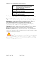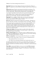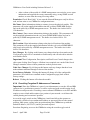
1
Canopy Cluster Management Module micro (CMMmicro) User Guide CMMmicro-UG-en Issue 2 Includes Software Release 2.1 April 2004 CMMmicro User Guide including Software Release 2.1 NOTICES Important Note on Modifications Intentional or unintentional changes or modifications to the equipment must not be made unless under the express consent of the party responsible for compliance. Any such modifications could void the user’s authority to operate the equipment and will void the manufacturer’s warranty. U.S. Federal Communication Commision (FCC) Notification This equipment complies with the limits for a Class B digital device, pursuant to Part 15 of the U.S. FCC Rules and with RSS-210 of Industry Canada. These limits are designed to provide reasonable protection against harmful interference in a residential installation. Operation is subject to the following two conditions: (1) This device may not cause harmful interference, and (2) This device must accept any interference received, including interference that may cause undesired operation. This equipment generates, uses, and can radiate radio-frequency energy and, if not installed and used in accordance with these instructions, may cause harmful interference to radio communications. If this equipment does cause harmful interference to radio or television reception, which can be determined by turning the equipment on and off, the user is encouraged to correct the interference by one or more of the following measures: Increase the separation between the affected equipment and the unit; Connect the affected equipment to a power outlet on a different circuit from that which the receiver is connected to; Consult the dealer and/or experienced radio/TV technician for help. Software License Terms and Conditions ONLY OPEN THE PACKAGE, OR USE THE SOFTWARE AND RELATED PRODUCT IF YOU ACCEPT THE TERMS OF THIS LICENSE. BY BREAKING THE SEAL ON THIS DISK KIT / CDROM, OR IF YOU USE THE SOFTWARE OR RELATED PRODUCT, YOU ACCEPT THE TERMS OF THIS LICENSE AGREEMENT. IF YOU DO NOT AGREE TO THESE TERMS, DO NOT USE THE SOFTWARE OR RELATED PRODUCT; INSTEAD, RETURN THE SOFTWARE TO PLACE OF PURCHASE FOR A FULL REFUND. THE FOLLOWING AGREEMENT IS A LEGAL AGREEMENT BETWEEN YOU (EITHER AN INDIVIDUAL OR ENTITY), AND MOTOROLA, INC. (FOR ITSELF AND ITS LICENSORS). THE RIGHT TO USE THIS PRODUCT IS LICENSED ONLY ON THE CONDITION THAT YOU AGREE TO THE FOLLOWING TERMS. Now, therefore, in consideration of the promises and mutual obligations contained herein, and for other good and valuable consideration, the receipt and sufficiency of which are hereby mutually acknowledged, you and Motorola agree as follows: Grant of License. Subject to the following terms and conditions, Motorola, Inc., grants to you a personal, revocable, non-assignable, non-transferable, non-exclusive and limited license to use on a single piece of equipment only one copy of the software contained on this disk (which may have been pre-loaded on the equipment)(Software). You may make two copies of the Software, but only for backup, archival, or disaster recovery purposes. On any copy you make of the Software, you must reproduce and include the copyright and other proprietary rights notice contained on the copy we have furnished you of the Software. Ownership. Motorola (or its supplier) retains all title, ownership and intellectual property rights to the Software and any copies, including translations, compilations, derivative works (including images) partial copies and portions of updated works. The Software is Motorola’s (or its supplier's) confidential proprietary information. This Software License Agreement does not convey to you any interest in or to the Software, but only a limited right of use. You agree not to disclose it or make it available to anyone without Motorola’s written authorization. You will exercise no less than reasonable care to protect the Software from unauthorized disclosure. You agree not to disassemble, decompile or reverse engineer, or create derivative works of the Software, except and only to the extent that such activity is expressly permitted by applicable law. Termination. This License is effective until terminated. This License will terminate immediately without notice from Motorola or judicial resolution if you fail to comply with any provision of this License. Upon such termination you must destroy the Software, all accompanying written materials and all copies thereof, and the sections entitled Limited Warranty, Limitation of Remedies and Damages, and General will survive any termination. Limited Warranty. Motorola warrants for a period of ninety (90) days from Motorola’s or its customer’s shipment of the Software to you that (i) the disk(s) on which the Software is recorded will be free from defects in materials and workmanship under normal use and (ii) the Software, under normal use, will perform substantially in accordance with Motorola’s published specifications for that release level of the Software. The written materials are provided "AS IS" and without warranty of any kind. Motorola's entire liability and your sole and exclusive remedy for any breach of the foregoing limited warranty will be, at Motorola's option, replacement of the disk(s), provision of downloadable patch or replacement code, or refund of the unused portion of your bargained for contractual benefit up to the amount paid for this software License. THIS LIMITED WARRANTY IS THE ONLY WARRANTY PROVIDED BY MOTOROLA, AND MOTOROLA AND ITS LICENSORS EXPRESSLY DISCLAIM ALL OTHER WARRANTIES, EITHER EXPRESS OF IMPLIED, INCLUDING BUT NOT LIMITED TO IMPLIED WARRANTIES OF MERCHANTABILITY AND FITNESS FOR A PARTICULAR PURPOSE AND NONINFRINGEMENT. MOTOROLA DOES NOT WARRANT THAT THE OPERATION OF THE SOFTWARE WILL BE UNINTERRUPTED OR ERROR-FREE, OR THAT DEFECTS IN THE SOFTWARE WILL BE CORRECTED. NO ORAL OR WRITTEN REPRESENTATIONS MADE BY MOTOROLA OR AN AGENT THEREOF SHALL CREATE A WARRANTY OR IN ANY WAY INCREASE THE SCOPE OF THIS WARRANTY. MOTOROLA DOES NOT WARRANT ANY SOFTWARE THAT HAS BEEN OPERATED IN EXCESS OF SPECIFICATIONS, DAMAGED, MISUSED, NEGLECTED, OR IMPROPERLY INSTALLED. BECAUSE SOME JURISDICTIONS DO NOT ALLOW THE EXCLUSION OR LIMITATION OF IMPLIED WARRANTIES, THE ABOVE LIMITATIONS MAY NOT APPLY TO YOU. Issue 2 April 2004 Page 2 of 40 CMMmicro User Guide including Software Release 2.1 Limitation of Remedies and Damages. Regardless of whether any remedy set forth herein fails of its essential purpose, IN NO EVENT SHALL MOTOROLA OR ANY OF THE LICENSORS, DIRECTORS, OFFICERS, EMPLOYEES OR AFFILIATES OF THE FOREGOING BE LIABLE TO YOU FOR ANY CONSEQUENTIAL, INCIDENTAL, INDIRECT, SPECIAL OR SIMILAR DAMAGES WHATSOEVER (including, without limitation, damages for loss of business profits, business interruption, loss of business information and the like), whether foreseeable or unforeseeable, arising out of the use or inability to use the Software or accompanying written materials, regardless of the basis of the claim and even if Motorola or a Motorola representative has been advised of the possibility of such damage. Motorola's liability to you for direct damages for any cause whatsoever, regardless of the basis of the form of the action, will be limited to the price paid for the Software that caused the damages. THIS LIMITATION WILL NOT APPLY IN CASE OF PERSONAL INJURY ONLY WHERE AND TO THE EXTENT THAT APPLICABLE LAW REQUIRES SUCH LIABILITY. BECAUSE SOME JURISDICTIONS DO NOT ALLOW THE EXCLUSION OR LIMITATION OF LIABILITY FOR CONSEQUENTIAL OR INCIDENTAL DAMAGES, THE ABOVE LIMITATION MAY NOT APPLY TO YOU. Maintenance and Support. Motorola shall not be responsible for maintenance or support of the software. By accepting the license granted under this agreement, you agree that Motorola will be under no obligation to provide any support, maintenance or service in connection with the Software or any application developed by you. Any maintenance and support of the Related Product will be provided under the terms of the agreement for the Related Product. Transfer. In the case of software designed to operate on Motorola equipment, you may not transfer the Software to another party except: (1) if you are an end-user, when you are transferring the Software together with the Motorola equipment on which it operates; or 2) if you are a Motorola licensed distributor, when you are transferring the Software either together with such Motorola equipment or are transferring the Software as a licensed duly paid for upgrade, update, patch, new release, enhancement or replacement of a prior version of the Software. If you are a Motorola licensed distributor, when you are transferring the Software as permitted herein, you agree to transfer the Software with a license agreement having terms and conditions no less restrictive than those contained herein. You may transfer all other Software, not otherwise having an agreed restriction on transfer, to another party. However, all such transfers of Software are strictly subject to the conditions precedent that the other party agrees to accept the terms and conditions of this License, and you destroy any copy of the Software you do not transfer to that party. You may not sublicense or otherwise transfer, rent or lease the Software without our written consent. You may not transfer the Software in violation of any laws, regulations, export controls or economic sanctions imposed by the U.S. Government. Right to Audit. Motorola shall have the right to audit annually, upon reasonable advance notice and during normal business hours, your records and accounts to determine compliance with the terms of this Agreement. Export Controls. You specifically acknowledge that the software may be subject to United States and other country export control laws. You shall comply strictly with all requirements of all applicable export control laws and regulations with respect to all such software and materials. U.S. Government Users. If you are a U.S. Government user, then the Software is provided with "RESTRICTED RIGHTS" as set forth in subparagraphs (c)(1) and (2) of the Commercial Computer Software-Restricted Rights clause at FAR 52 227-19 or subparagraph (c)(1)(ii) of the Rights in Technical Data and Computer Software clause at DFARS 252.227-7013, as applicable. Disputes. You and Motorola hereby agree that any dispute, controversy or claim, except for any dispute, controversy or claim involving intellectual property, prior to initiation of any formal legal process, will be submitted for non-binding mediation, prior to initiation of any formal legal process. Cost of mediation will be shared equally. Nothing in this Section will prevent either party from resorting to judicial proceedings, if (i) good faith efforts to resolve the dispute under these procedures have been unsuccessful, (ii) the dispute, claim or controversy involves intellectual property, or (iii) interim relief from a court is necessary to prevent serious and irreparable injury to that party or to others. General. Illinois law governs this license. The terms of this license are supplemental to any written agreement executed by both parties regarding this subject and the Software Motorola is to license you under it, and supersedes all previous oral or written communications between us regarding the subject except for such executed agreement. It may not be modified or waived except in writing and signed by an officer or other authorized representative of each party. If any provision is held invalid, all other provisions shall remain valid, unless such invalidity would frustrate the purpose of our agreement. The failure of either party to enforce any rights granted hereunder or to take action against the other party in the event of any breach hereunder shall not be deemed a waiver by that party as to subsequent enforcement of rights or subsequent action in the event of future breaches. Hardware Warranty in U.S. Motorola U.S. offers a warranty covering a period of 90 days from the date of purchase by the customer. If a product is found defective during the warranty period, Motorola will repair or replace the product with the same or a similar model, which may be a reconditioned unit, without charge for parts or labor. IN NO EVENT SHALL MOTOROLA BE LIABLE TO YOU OR ANY OTHER PARTY FOR ANY DIRECT, INDIRECT, GENERAL, SPECIAL, INCIDENTAL, CONSEQUENTIAL, EXEMPLARY OR OTHER DAMAGE ARISING OUT OF THE USE OR INABILITY TO USE THE PRODUCT (INCLUDING, WITHOUT LIMITATION, DAMAGES FOR LOSS OF BUSINESS PROFITS, BUSINESS INTERRUPTION, LOSS OF BUSINESS INFORMATION OR ANY OTHER PECUNIARY LOSS, OR FROM ANY BREACH OF WARRANTY, EVEN IF MOTOROLA HAS BEEN ADVISED OF THE POSSIBILITY OF SUCH DAMAGES. (Some states do not allow the exclusion or limitation of incidental or consequential damages, so the above exclusion or limitation may not apply to you.) IN NO CASE SHALL MOTOROLA’S LIABILITY EXCEED THE AMOUNT YOU PAID FOR THE PRODUCT. Trademarks, Product Names, and Service Names Issue 2 April 2004 Page 3 of 40 CMMmicro User Guide including Software Release 2.1 MOTOROLA, the stylized M Logo and all other trademarks indicated as such herein are trademarks of Motorola, Inc. ® Reg. U.S. Pat & Tm. Office. Canopy is a trademark of Motorola, Inc. All other product or service names are the property of their respective owners. © 2004 Motorola, Inc. All rights reserved. http://www.motorola.com/canopy Issue 2 April 2004 Page 4 of 40 CMMmicro User Guide including Software Release 2.1 Table of Contents 1 2 Introduction _______________________________________________________ 7 1.1 Welcome __________________________________________________________ 7 1.2 Finding the Information You Need _____________________________________ 7 1.3 Document Change History ____________________________________________ 7 1.4 Feedback on Documentation __________________________________________ 7 1.5 Technical Support___________________________________________________ 7 Product Description _________________________________________________ 9 2.1 2.1.1 2.1.2 2.1.3 2.1.4 2.1.5 2.1.6 2.1.7 2.1.8 2.1.9 2.2 2.2.1 2.2.2 3 4 Services and Features ________________________________________________ 9 Network Interconnection ____________________________________________________ 9 Power Distribution _________________________________________________________ 9 Sync Distribution __________________________________________________________ 9 Reduced Cables (Compared with CMM2)______________________________________ 10 NTP (Network Time Protocol) Server _________________________________________ 10 Browser Interface to Managed Switch_________________________________________ 10 SNMP Interface to Managed Switch __________________________________________ 10 Lightning Protection_______________________________________________________ 11 Weatherized Enclosure_____________________________________________________ 11 Hardware and Software _____________________________________________ 11 CMMmicro Hardware _____________________________________________________ 11 CMMmicro Software ______________________________________________________ 15 Planning and Background Information ________________________________ 16 3.1 Connectivity ______________________________________________________ 16 3.2 Electrical Requirements _____________________________________________ 17 3.3 Cabling __________________________________________________________ 17 3.4 GPS _____________________________________________________________ 18 3.5 Lightning and Grounding ___________________________________________ 18 3.6 Networking _______________________________________________________ 19 3.7 Simple Network Management Protocol (SNMP) _________________________ 19 Installation and Operation Procedures_________________________________ 20 4.1 4.1.1 4.1.2 4.1.3 Prepare Cables ____________________________________________________ 20 Tools for Fabricating Cables ________________________________________________ 20 GPS Antenna Coax Cable __________________________________________________ 20 Ethernet Cables __________________________________________________________ 20 4.2 Unpack CMMmicro ________________________________________________ 22 4.3 Configure and Test _________________________________________________ 22 4.3.1 4.3.2 4.3.3 4.3.4 4.3.5 Procedure: Configure CMMmicro ____________________________________________ Status Page ______________________________________________________________ Configuration Page________________________________________________________ Overriding Forgotten IP Addresses or Passwords ________________________________ Event Log _______________________________________________________________ Issue 2 April 2004 Page 5 of 40 22 23 25 29 30 CMMmicro User Guide including Software Release 2.1 4.3.6 4.3.7 4.4 4.4.1 4.4.2 4.4.3 4.4.4 4.4.5 4.5 5 6 GPS Status ______________________________________________________________ 31 Port MIB (Ethernet Stats)___________________________________________________ 32 Install ____________________________________________________________ 33 Power Supply Install ______________________________________________________ AP and BH Mounting Procedure _____________________________________________ CMMmicro Mounting Procedure_____________________________________________ GPS Antenna Mounting Procedure ___________________________________________ Cable Install _____________________________________________________________ 33 34 34 34 35 Verify ____________________________________________________________ 36 Software Installation Procedures _____________________________________ 37 5.1 Software Components and Version Information _________________________ 37 5.2 CMMmicro Upgrade _______________________________________________ 37 5.3 TFTP and Telnet User name and Password _____________________________ 38 Specifications _____________________________________________________ 40 6.1 CMMmicro Physical________________________________________________ 40 6.2 Provided DC Power Converter _______________________________________ 40 6.3 CMMmicro Power _________________________________________________ 40 6.4 Cable Specifications ________________________________________________ 40 Table of Figures Figure 1: Cluster Management Module micro ...................................................................................... 12 Figure 2: CMMmicro Circuit Board ..................................................................................................... 13 Figure 3: CMMmicro Door Label.......................................................................................................... 14 Figure 4: CMMmicro Connectivity ....................................................................................................... 16 Figure 5: Straight-through Ethernet Cable Pin-Out Information........................................................ 21 Figure 6: Crossover Ethernet Cable Pin-Out Information................................................................... 22 Figure 7: CMMmicro Status Page ......................................................................................................... 24 Figure 8:CMMmicro Configuration Page ............................................................................................. 26 Figure 9: CMMmicro GPS Status Page................................................................................................. 31 Figure 10: Port MIB Page ...................................................................................................................... 32 Figure 11: Detail of GPS antenna mounting ......................................................................................... 35 Table of Tables Table 1: MAC addresses (ESNs) compatible with CMMmicro Table 2: DC Cable Wire Size versus Cable Length Table 3: Cable Ordering Information Table 4: Files in Downloaded Zip File Table 5: TFTP and Telnet Passwords Issue 2 April 2004 Page 6 of 40 9 17 18 37 39 CMMmicro User Guide including Software Release 2.1 1 Introduction 1.1 Welcome This User Guide supports planning, installation, and operation of a Cluster Management Module micro (CMMmicro). The following abbreviations are used throughout these notes: BH: Backhaul, either Timing Master or Timing Slave module BHM: Backhaul – Timing Master module BHS: Backhaul – Timing Slave module AP: Access Point module SM: Subcriber Module 1.2 Finding the Information You Need If you are viewing this on Adobe Reader: • Take advantage of the page numbers Adobe Reader shows at the bottom of the screen and in the “thumbnails”. They are the same as the page numbers in the Table of Contents. • Take advantage of the Find command (Ctrl F) to find a word or phrase you are looking for. For information on other elements of a Canopy network and how to install and operate them, please refer to http://www.motorola.com/canopy for the latest versions of User Guides and supporting information. 1.3 Document Change History Issue 2 - Supports CMMmicro Software Release 2.1 o NTP (Network Time Protocol) Server o Changes to user interface o Upgrade procedures Issue 1 - Initial issue 1.4 Feedback on Documentation We welcome your feedback on Canopy documentation, including feedback on structure, content, accuracy, completeness, or other comments you have. Please send your feedback to [email protected]. 1.5 Technical Support If issues are encountered during installation of the CMMmicro, the Canopy support team is here to help. Following is the escalation path for resolving issues: 1. Check this document, especially the Troubleshooting section. Issue 2 April 2004 Page 7 of 40 CMMmicro User Guide including Software Release 2.1 2. Escalate to your Canopy supplier. 3. Escalate to Canopy Technical Support or other designated Tier 3 technical support: Canopy Technical Support Hours of Operation: 7am-11pm EST, Mon - Sun 1-888-605-2552 or +1-217-824-9742 email: [email protected] Before you call or send e-mail, please have the following information: • Information on your network including IP addresses and MAC addresses. • Software release running on modules having issues. Issue 2 April 2004 Page 8 of 40 CMMmicro User Guide including Software Release 2.1 2 Product Description The following sections describe the CMMmicro, first in terms of the services and features it offers and then in terms of the hardware and software it consists of. 2.1 Services and Features A CMMmicro provides the following services and features: 2.1.1 Network Interconnection A CMMmicro contains an 8-port managed switch which supports Power over Ethernet (PoE) on each port and connects up to 8 APs, BHMs, BHSs, or Ethernet feeds. A CMMmicro auto-negotiates to match inputs that are either 100 BaseT or 10 BaseT, and either full duplex or half duplex. These parameters can also be set by the operator if so desired. 2.1.2 Power Distribution A CMMmicro distributes power to up to 8 APs, BHMs, or BHSs using Power over Ethernet (PoE). Ports can be powered or not powered, using a browser interface to the managed switch. Input to a CMMmicro is nominal 24 V DC, and output to the modules is also nominal 24 V DC. The CMMmicro comes with a separate 115/230 V AC to 24 V DC power converter. 2.1.3 Sync Distribution A CMMmicro distributes synchronization to Access Point modules (APs) and Backhaul Timing Master modules (BHMs). It receives timing information from Global Positioning System (GPS) satellites through an antenna, and distributes the synchronization signal to up to 8 modules (APs or BHMs). The 1 pulse-per-second timing received from the GPS is embedded in the 24 V power that is sent to each module. Important! Most Canopy APs and BHs are compatible with the CMMmicro, but some early APs and BHs manufactured before October, 2002, do not support sync on the power leads of the Ethernet port and therefore cannot be used with the CMMmicro. The following table shows AP and BH compatibility with CMMmicro. Table 1: MAC addresses (ESNs) compatible with CMMmicro MAC Address (ESN) Not Compatible with CMMmicro Compatible with CMMmicro 5.2 Modules ≤ 0a003ef00f79 ≥ 0a003ef00f7a 5.7 Modules ≤ 0a003e0021c8 ≥ 0a003e0021c9 Issue 2 April 2004 Page 9 of 40 CMMmicro User Guide including Software Release 2.1 Important! APs and BHs must be running Canopy Release 4.0 or greater to allow them to use the sync signal embedded in the power-over-Ethernet. Synchronization is the key to operation of a Canopy network. An isolated AP or AP cluster 5 miles (8 km) from any other Canopy equipment, or an isolated, standalone backhaul link, may run on sync generated by the AP or BHM. Any larger network requires external GPS synchronization like that provided by the CMMmicro or CMM2. If one AP or BH is not synchronized, then it may transmit during a receive cycle of the other modules and cause the receiver to be desensed. 2.1.4 Reduced Cables (Compared with CMM2) A CMMmicro provides Ethernet, power, and synch to a Canopy AP or BH over one cable terminating in an RJ-45 connector. (A CMM2 requires two cables per modules one provides Ethernet and power terminating in an RJ-45 connector, and the other provides synch over a serial interface terminating in an RJ-11 connector.) Important! This feature - halving the number of cables compared with a CMM2 - gives a significant cost reduction. The savings are dependent on site layout, cable costs, and installation costs. Halving the number of cable and connections also reduces possible trouble points or failure points. Important! The second CMM2 cable per module is a serial interface carrying GPS status and time & date, as well as synch. Without this cable, the GPS status information is available at the CMMmicro, instead of at each connected BHM or AP as with the CMM2. 2.1.5 NTP (Network Time Protocol) Server With CMMmicro software Release 2.1, the CMMmicro serves as an NTP server. A coordinated feature in Canopy Release 4.2 allows the BHMs and APs to be set with the IP address of an NTP server – the IP address of the CMMmicro. With these two features, BHMs and APs connected to a CMMmicro can again receive network time like BHMs and APs connected to a CMM2, albeit using a different method. 2.1.6 Browser Interface to Managed Switch A CMMmicro has Status, Configuration, GPS Status and other pages accessible through any browser, using the CMMmicro’s IP address. The CMMmicro can be configured and monitored through these pages, and the power to each of the 8 ports turned on or off. GPS status including antenna connection status is now available at the CMM, which can help in troubleshooting synch issues. 2.1.7 SNMP Interface to Managed Switch A CMMmicro can be managed with a Network Manager using Simple Network Management Protocol (SNMP). Most functionality provided by the CMMmicro’s web browser interface is supported by the Canopy Enterprise MIB. The necessary Management Information Bases (MIBs) are included in the MIB files in the Canopy 4.2 Software Release. Issue 2 April 2004 Page 10 of 40 CMMmicro User Guide including Software Release 2.1 2.1.8 Lightning Protection The CMMmicro electrical design allows it to “ride-out” electrical surges generated by near-field lightning. This affords a level of protection to the CMMmicro, but still requires proper lightning protection on the tower or other CMMmicro location. Important! The ground bonding point on the CMMmicro is the ground connection on the terminal block. This bonding point must be tied to solid ground following local or national electrical standards. Important! Grounding of the CMMmicro should be one part of an overall lightning protection plan including grounding of the tower or location the APs or BHs are mounted on. 2.1.9 Weatherized Enclosure A CMMmicro comes in a lockable weatherized enclosure. The CMMmicro can be mounted on a tower, on a rooftop, on the outside of a tower electronics hut, inside a tower electronics hut, or inside a building wiring closet. A CMMmicro in its weatherized enclosure is smaller and lighter than the CMM2 in its weatherized enclosure. Important! The CMMmicro is not designed to contain the 24 V DC power converter in the same weatherized enclosure, unlike the CMM2. The power converter can be located in a hut or wiring closet, or in its own weatherized enclosure. In many applications this gives additional flexibility in placement of the CMMmicro. For example, the power supply can be in a hut and the CMMmicro half-way up a tower, with 24 V (not 115/230 V AC) between them. 2.2 Hardware and Software A CMMmicro consists of the following hardware and software: 2.2.1 CMMmicro Hardware The following picture shows the CMMmicro. Callouts are listed below the picture. Issue 2 April 2004 Page 11 of 40 CMMmicro User Guide including Software Release 2.1 Figure 1: Cluster Management Module micro 1. Weatherized enclosure 2. Thumb-screw/slot-screwdriver door fasteners 3. Punch-out for padlock 4. Ethernet switch and power module 5. Female BNC connector 6. Water-tight strain relief connectors • 4-hole silicone bushing inside each connector (for up to 4 Ethernet cables) • additional 1-hole silicone bushing provided for use with thicker power cable 7. Flange for attachment (stainless steel so it grounds to tower or building) using U bolts (provided) or other hardware such as screws or lag bolts or attachment straps (not provided). 8. Ground strap to ground door to enclosure 9. 100 W 115/230 V AC to 24 V DC power converter, with 10 ft (3 m) of DC power cable (not shown) Issue 2 April 2004 Page 12 of 40 CMMmicro User Guide including Software Release 2.1 10. 6 ft (1.8 m) AC power cord for 24 V power converter (not shown) The following picture shows the CMMmicro circuit board. Callouts are listed below the picture. Figure 2: CMMmicro Circuit Board 1. 24 V DC power connection on terminal block (+V) 2. 24 V DC ground connection on terminal block (-V) 3. Ground bonding point for CMMmicro. Ground connection on terminal block, for grounding to Protective Earth (PE) 4. Female BNC connector for connecting to coax cable from GPS antenna Important! The CMMmicro coax cable uses a male N (screw-on) connector at the antenna end, and a BNC (easy quarter twist) male connector at the CMM end. The CMM2 coax cable uses a male N connector at each end. If replacing a CMM2 with a CMMmicro, use an N to BNC adapter, or change the cable. 5. Status display of 8 green LEDs. The left LEDs show the number of satellites visible to the CMMmicro (1, 2, ≥ 4, and ≥ 8), and the right LEDs show status: • RDY (Ready) – Flashing LED indicates CMMmicro software has booted and is operational. LED continues to flash during normal operation. Issue 2 April 2004 Page 13 of 40 CMMmicro User Guide including Software Release 2.1 • SYNC – Constant LED indicates CMMmicro is receiving signal from the GPS antenna and is able to derive sync. • DFLT (default) – Constant LED indicates CMMmicro has booted with Override switch in down/override position, and therefore with default IP address and no password. • PWR (power) – Constant LED indicates CMMmicro has power. 6. 8-port Ethernet connection block with 2 LEDs per port indicating port status. 7. Constant red LED to the right of each port indicates the port is powered with 24 V DC (controlled by the CMMmicro Configuration page). 8. Constant green LED to the left of each port indicates the port is detecting Ethernet connectivity. 9. Override toggle switch, for overriding a lost or unknown IP address or password. Down is normal position, while rebooting in the up position brings the CMMmicro up with the default IP address and no password required. 10. Timing pulse jack – not used The following diagram is the label included inside the door of a CMMmicro. It gives additional insight into the layout of the CMMmicro. Figure 3: CMMmicro Door Label Issue 2 April 2004 Page 14 of 40 CMMmicro User Guide including Software Release 2.1 For additional hardware details, please refer to the Specifications section. 2.2.2 CMMmicro Software The CMMmicro contains both a Programmable Logic Device (PLD) and software. Minimum levels of each are shown in the following table: Programmable Logic Device 5 (PLD) Version Software Version Canopy CMM 2.0.8 Issue 2 April 2004 Page 15 of 40 CMMmicro User Guide including Software Release 2.1 3 Planning and Background Information 3.1 Connectivity The following diagram shows CMMmicro connectivity. Figure 4: CMMmicro Connectivity Issue 2 April 2004 Page 16 of 40 CMMmicro User Guide including Software Release 2.1 3.2 Electrical Requirements Power input to the CMMmicro is nominal 24 V DC. Included with the CMMmicro is a 24 V DC power converter that uses an input of nominal 115 V 60 Hz or 230 V 50 Hz current. The power converter plugs into an AC receptacle using a standard IEC power cord (commonly used for computers, stereo equipment, and other electronic equipment). Different cords are available to provide region- or country-specific AC plugs. The CMMmicro requires an input voltage between 21.5 and 26.5 V DC. At 24 V, the maximum draw is 3.36 A with all 8 ports connected to APs and BHs. The following table shows the resulting wire size needed versus cable length. Table 2: DC Cable Wire Size versus Cable Length Cable length from CMMmicro to 24 V Power Converter Wire size 270 ft (~80 m) 12 AWG (4 mm2) 450 ft (~140 m) 10 AWG (6 mm2) 675 ft (~205 m) 8 AWG (10 mm2) 950 ft (~290 m) 6 AWG (16 mm2) Ensure the site design conforms to the National Electrical Code (NEC) or appropriate country and local codes. If uncertain of code requirements, obtain the services of a licensed electrician. 3.3 Cabling Important! Shielded cables are strongly recommended for all Canopy infrastructure cabling (between APs, BHs, and CMMs) due to the RF environment around typical installations. Important! The shield should be terminated on both ends of the cable. Either straight or cross-over cables can be used with the CMMmicro as each port autosenses the correct Ethernet termination. The cabling design should include best practices associated with cabling, including: • Include a “service loop” at both ends of the cable. The service loop provides an additional foot or two (0.6 m) of cable for thermal expansion and contraction and re-termination to the connector if needed. • Use di-electric grease on all connectors to reduce the potential for corrosion. • For vertical runs, provide cable support and strain relief per local or national practice. Issue 2 April 2004 Page 17 of 40 CMMmicro User Guide including Software Release 2.1 The Ethernet limit of a maximum 328 ft (100 m) between managed elements applies. The CMMmicro must be within 328 cable ft (100 cable meters) of the furthest AP, BH, or any router or managed element it is connected to. Ethernet and GPS/coax cables can be ordered from Best-Tronics Manufacturing, Inc. at http://www.best-tronics.com/motorola.htm. Ordering information is shown in Table 3: Cable Ordering Information. Table 3: Cable Ordering Information Cable Type Cable Description Best-Tronics part number Ethernet Cables RJ-45 to RJ-45 straight shielded Ethernet cable using outdoor STP cat 5E (-40 to 150 °C and UV) BT-0562S-XXX (where XXX is length in feet) GPS/coax cable BNC to N GPS antenna cable BT-0716-XXX (where XXX is using outdoor LMR-195 length in feet) cable Information to use when specifying or fabricating cables is included in Section 4.1, Prepare Cables, on page 20. 3.4 GPS The GPS antenna must be located so it has a clear view of the sky (20 degrees off the horizon). The antenna needs to be within 100 cable ft (30.5 cable meters) of the CMMmicro, using LMR-195 coaxial cable). The GPS antenna does not need to be particularly high at the site. When placing the antenna, consider its exposure to lightning. Since Canopy uses the sync from GPS but not altitude, latitude, or longitude, it can be placed anywhere vertical or horizontal within the maximum cable distance – it just needs a clear view of the sky. 3.5 Lightning and Grounding The ground or Protective Earth (PE) terminal on the internal terminal block is the ground bonding point in the CMMmicro. The enclosure, the ground or Protective Earth (PE) terminal on the internal terminal block, and the -V terminal on the internal terminal block are all on the same ground circuit. Connect the ground or Protective Earth (PE) terminal on the internal terminal block to the site ground window or grounding plate, using a gage of wire as specified in applicable local or national electrical codes. The terminal block is sized for 8 AWG (10 mm2) solid, 10 AWG (6 mm2) solid or stranded, or 12 AWG (4 mm2) solid or stranded wire. Issue 2 April 2004 Page 18 of 40 CMMmicro User Guide including Software Release 2.1 For best protection, ensure the CMMmicro is well-grounded (completely to ground) through the tower or supporting structure using the stainless steel flanges or a ground strap. Also ensure the location is properly grounded for lightning protection according to all applicable national and local codes. If a wired Ethernet feed is used, run the feed through a Canopy Surge Suppressor at the far end, near ground. Mount all equipment (AP, CMM, or GPS antenna) at least 2 feet (~0.6 m) below the highest point at the site for lightning strike mitigation. It is highly recommended that the site have a lightning protection system installed. 3.6 Networking Assign the CMMmicro an IP address consistent with your network’s IP addressing plan. In most cases, you will want the CMM only accessible within your network, so assign it an address from the ranges which are not routed over the internet: • • • • 10.0.0.0 – 10.255.255.255 172.16.0.0 – 172.31.255.255 192.168.0.0 – 192.168.255.255 169.254.0.0 – 169.254.255.255 You can also assign subnet mask and network gateway for the CMMmicro. The factory default networking information is: • • • • 3.7 Unique MAC address IP address of 169.254.1.1 Subnet mask of 255.255.0.0 Network gateway of 169.254.0.0 Simple Network Management Protocol (SNMP) Like the other elements in a Canopy network, a CMMmicro can be managed using an SNMP Network Manager. The Canopy Enterprise MIB for Release 4.1, consisting of 5 MIB definition files, includes MIB objects needed to monitor and control a CMMmicro. Issue 2 April 2004 Page 19 of 40 CMMmicro User Guide including Software Release 2.1 4 Installation and Operation Procedures Installation of a CMMmicro consists of the following steps: • Prepare Cables • Unpack CMMmicro • Configure and Test • Install • Verify During each step, you will want to also perform similar actions on other Canopy equipment (APs and BHs) being installed at the same location. 4.1 Prepare Cables If you have purchased cables, do a quality check on them at this step. If you are fabricating cables, the following sections give information needed. Note that the leading cause of technical support issues on the CMM is due to cabling issues. Quality materials, training in cable fabrication, and care in construction prevent future problems. 4.1.1 Tools for Fabricating Cables The following tools may be needed for fabricating cables: • • • • • • • • N-male connector crimping tool RJ-45 crimping tool electrician scissors wire cutters wire stripper soldering iron solder cable testing device. 4.1.2 GPS Antenna Coax Cable The following materials are required for GPS antenna coax cable: • Up to 100 feet (30.5 meters) of LMR-195 coaxial cable • Temperature range of -40°F to +131°F (-40°C to +55°C) • Must be rated for UV light protection • 1 Times Microwave N-male connector (Times Microwave part number TC200-NM) or equivalent connector. • 1 Times Microwave BNC-male connector (Times Microwave part number TC-200-BM) or equivalent connector. 4.1.3 Ethernet Cables Issue 2 April 2004 Page 20 of 40 CMMmicro User Guide including Software Release 2.1 Important! Shielded cables are strongly recommended for all Canopy infrastructure cabling (between APs, BHs, and CMMs) due to the RF environment around typical installations. Important! The shield should be terminated on both ends of the cable. The following materials are required for the Ethernet cables • RJ-45 Connectors • Up to 328 feet (100 meters) of Cat 5E cable. • Temperature range of -40°F to +131°F (-40°C to +55°C) • Must be rated for UV light protection The following figures show connector pin-out and wire color information for straightthough and crossover Ethernet cables. Either straight-through or crossover cables can be used, as the CMMmicro ports auto-sense the Ethernet termination and can handle either. In both cases, pins 7 and 8 carry power to the Canopy modules. The straight-through cable uses the EIA/TIA-568B wire color-code standard. Figure 5: Straight-through Ethernet Cable Pin-Out Information Issue 2 April 2004 Page 21 of 40 CMMmicro User Guide including Software Release 2.1 Figure 6: Crossover Ethernet Cable Pin-Out Information 4.2 Unpack CMMmicro Upon receipt, carefully inspect all shipping boxes for signs of damage. If there is damage, immediately notify the transportation company. Unpack equipment, making sure that all ordered components have arrived. Save the packing materials - they can be used for transportation of the equipment to and from installation sites. 4.3 Configure and Test The best practice is to connect all the modules (BHs, APs, GPS antenna, and CMMmicro) with the intended cables in a bench or depot or lab setting and configure and verify the modules, before beginning the physical installation. Circumstances or local practice may require a different approach – modify the following procedures appropriately. 4.3.1 Procedure: Configure CMMmicro 1. Start with the 24 V DC power converter UNCONNECTED to AC mains. (Don’t plug it into an AC receptacle yet.) Issue 2 April 2004 Page 22 of 40 CMMmicro User Guide including Software Release 2.1 2. Connect the CMMmicro to the 24 V power converter using the 10-foot (3 m) cord attached to the power converter. The lead with black insulation with a white stripe is 24 V DC and connects to +V on the CMMmicro terminal block. The lead with black insulation and no white stripe is Return and connects to -V on the CMMmicro terminal block. If the site design is such that the cable distance from the CMMmicro to the 24 V power converter is more than 10 feet (3 m), install additional DC cable per local electrical code, using connector box and conduit per code. 3. Connect the the AC power cord to the DC power converter and to an AC receptacle. 4. Wait for the CMMmicro to boot and become ready. Completion of booting takes under a minute and is indicated by a flashing green RDY LED. The LED will continue to flash during normal operation. 5. Observe which, if any, Ethernet ports are powered, as indicated by a red LED to the right of the Ethernet port. Figure 2: CMMmicro Circuit Board and Figure 3: CMMmicro Door Label show the position of this +24 V OUT LED indicator. Connect a browser-equipped computer to any unpowered port (one without the red LED lit) on the 8-port Ethernet block of the CMMmicro using either a straight-through or crossover Ethernet cable (the CMMmicro auto-senses the cable type). Caution! Do not connect devices other than Canopy APs and BHs to a powered port. Powered ports are indicated by a red LED to the right of the port. A powered port has 24 V DC on pins 7 and 8 and 24 V return on pins 4 and 5, and could damage equipment like computers and routers. 6. Configure your computer to use DHCP, with proxies turned off (or no proxies set, depending on your operating system) in your network settings. 7. Connect to the CMMmicro using your browser and the CMMmicro’s default IP address of 169.254.1.1 8. Your browser should now display the CMM Status page. 9. Proceed to configure the IP address and turn on power to selected ports using the Configuration Page described in Section 4.3.3. 10. Set APs and BHs that will connect to the CMMmicro to Sync to Received Signal (Power Port) on their Configuration page. Configure other AP and BH parameters using their user manuals. Important! Each AP or BH that connects to a CMMmicro must have the Sync Input parameter on the module’s Configuration page set to Sync to Received Signal (Power Port). 4.3.2 Status Page Issue 2 April 2004 Page 23 of 40 CMMmicro User Guide including Software Release 2.1 The status page shows status of the system. Figure 7: CMMmicro Status Page The following parameters are displayed: Link: A red indicator means the port is active and has detected Ethernet traffic. A greyed-out indicator means the port is not active and no traffic is detected. 100BaseT: A red indicator means the port has auto-negotiated to a 100-BaseT connection. A greyed-out indicator means the port has auto-negotiated to a 10-BaseT connection. (The convention is similar to that seen on many routers and network interface cards.) If the far end (an AP, a BH, a router) has been set to auto-negotiate, the CMMmicro will link at 100-BaseT. Full Duplex: A red indicator means the port has auto-negotiated to a Full Duplex connection. A greyed-out indicator means the port has auto-negotiated to a Half Duplex connection. (The convention is similar to that seen on many routers and network interface cards.) Powered: A red indicator means the port is powered with 24 V DC for providing power to an AP or BH. A greyed-out indicator means the port is not powered. Port power is turned on and off using the Configuration page. A CMMmicro comes from the factory with no Ethernet ports powered. Caution! Do not connect devices other than Canopy modules to a powered port. A powered port has 24 V DC on pins 7 and 8, and could potentially damage other networking equipment including computers. Issue 2 April 2004 Page 24 of 40 CMMmicro User Guide including Software Release 2.1 Device Type: Displays the MAC address of the module. PLD Version (Programmable Logic Device): Displays the version of the PLD that is currently loaded into the module. Please make note of this information when obtaining technical support. Software Version: Displays the version of the software that is currently loaded into the module. Please make note of this information when obtaining technical support. System Time: Displays the current time. If the CMMmicro is connected to a GPS antenna then the time will be Greenwich Mean Time (GMT). Satellites Visible: Displays number of satellites visible to the GPS antenna. Latitude: Displayed when connected to a working GPS antenna. Height: Displayed when connected to a working GPS antenna. Uptime: Time since last boot of the CMM. Satellites Tracked: Displays number of satellites the GPS in the CMM is tracking. Longitude: Displayed when connected to a working GPS antenna. Tracking Mode: Displayed when connected to a working GPS antenna. Sync Pulse Status: Indicates status of sync pulse. Site Name: Displays administrative information entered by the operator on the Configuration page. Site Contact: Displays administrative information entered by the operator on the Configuration page. 4.3.3 Configuration Page The Configuration page shows the current value of configurable parameters and allows the user to change those values. Issue 2 April 2004 Page 25 of 40 CMMmicro User Guide including Software Release 2.1 Figure 8:CMMmicro Configuration Page GPS Timing Pulse: Select Master. Slave is for future use. Important! If the GPS Timing Pulse is set to Slave, the CMMmicro will not sync off the GPS unit and therefore will not work. Lan1 IP: Enter the IP address that will be associated with the Ethernet connection on this module. The default address is 169.254.1.1. If the IP address is forgotten, the operator can override the IP address using the Override Switch. See steps at end of section for details. LAN1 Subnet Mask: Enter the appropriate subnet mask for the module to “talk” on the network. The default value for this parameter is 255.255.0.0. Default Gateway: Enter the appropriate gateway for the module to “talk” on the network. The default for this parameter is 169.254.0.0. Port Configuration: Allows the operator to force a port to a given speed and duplex state, per the following table. Issue 2 April 2004 Page 26 of 40 CMMmicro User Guide including Software Release 2.1 Auto Allows the port to attempt to auto-negotiate speed and duplex state. Recommended, default, configuration. 100FDX 100 Mbps, Full Duplex 100HDX 100 Mbps, Half Duplex 10FDX 10 Mbps, Full Duplex 10 HDX 10 Mbps, Half Duplex No reboot is required, so you can make Port Configuration changes without dropping communication to APs and BHs connected to the CMMmicro. Important! Port Configuration changes take effect upon clicking Save Changes, without a Reboot. Undo Saved Changes will not return the values to the previous state. Description: The operator can enter a name or description of the port, such as an abbreviation and partial IP address of the module connected to that port. No reboot is required, so you can make Description changes without dropping communication to APs and BHs connected to the CMMmicro. Important! Description changes take effect upon clicking Save Changes, without a Reboot. Undo Saved Changes will not return the values to the previous state. Port Power Control: Controls 24 V DC power on each port. Turn power on to ports connected to Canopy APs or BHs. Ensure power is left off on ports connected to routers, computers, or other network equipment. Caution! Do not turn on power to a port until you have confirmed what is connected to it. Powered ports should only be connected to Canopy APs and BHs. A powered port has 24 V DC on pins 7 and 8, and could potentially damage networking equipment, including computers and routers. Issue 2 April 2004 Page 27 of 40 CMMmicro User Guide including Software Release 2.1 Important! Port Power Control changes take effect upon clicking Save Changes. A Reboot is not required, nor can the Undo Saved Changes return the values to the previous state. Display-Only Access: Enter the same password in both fields for verification. The display-only password, when used with a Full Access password, will allow only view activities to the module. When the display-only password is set and not the fullaccess password, the display-only password will be tied to telnet and TFTP sessions to the module. If the full-access password is also set then it has precedence on the telnet and TFTP sessions. If the password is forgotten, the operator will need physical access to the module. See steps at end of section for details. Important! If you set only the “Display-Only Access” password, that password gives full access (read and write) to make configuration changes on the modules interface pages module for TFTP and telnet, as well as. Full Access: Enter the same password in both fields for verification. The full-access password, when used, will allow view and change activities to the module. When the full-access password is set, the password will also be tied to telnet and TFTP sessions to the module. When prompted for the password via the web-based interface, no username is required – the field can be left blank. However when prompted for the password via a telnet or TFTP session, the user name that must be used is “root”. If the password is forgotten, the operator will need physical access to the module. See steps at end of section for details. Webpage Auto Update: Enter time period (in seconds) desired to have the web browser refresh the web-based interface. The default setting is 0, which will cause the web-based interface to never refresh. SNMP Community String: Enter a string that will allow a SNMP management server accessibility to the SNMP information. There must not be any spaces in the community string. The default for this parameter is “Canopy”. SNMP Accessing Subnet: enter the network that will be allowed to access SNMP information from the canopy module. There are two pieces of information needed: • The network in the form of xxx.xxx.xxx.xxx • The CIDR (Classless Interdomain Routing) prefix length in the form of /xx An example would be 198.32.0.0/16 where /16 is a subnet mask of 255.255.0.0. If you need more background on this topic, do an Internet search on Classless Interdomain Routing will provide more information on this topic. The default is to allow all networks access. Trap Address: enter in an IP address (xxx.xxx.xxx.xxx) of an SNMP management server where trap information can be sent. A trap is a way for the module to tell the monitoring system that something has happened. The following is a scenario where a trap would be sent: Issue 2 April 2004 Page 28 of 40 CMMmicro User Guide including Software Release 2.1 • After a reboot of the module if a SNMP management server tried to access agent information and supplied the wrong community string, wrong SNMP version number, or came from the wrong accessing subnet. Permission: Check “Read Only” if you want the Network Manager to only be able to read, and not write or set, CMMmicro configuration items. Site Name: Enter information relating to a name given to the physical module. This parameter will set the supplied information into the sysName SNMP MIB-II object and can be polled by a SNMP management server. The buffer size for this field is 128 characters. Site Contact: Enter contact information relating to the module. This parameter will set the supplied information into the sysContact SNMP MIB-II object and can be polled by a SNMP management server. The buffer size for this field is 128 characters. Site Location: Enter information relating to the physical location of the module. This parameter will set the supplied information into the sysLocation SNMP MIB-II object and can be polled by a SNMP management server. The buffer size for this field is 128 characters. Save Changes: By clicking on this button, any changes that have been made on the Configuration page will be committed to flash memory and will take effect after the next module reboot. Important! Port Configuration, Description, and Port Power Control changes take effect upon clicking Save Changes. A Reboot is not required, nor can the Undo Saved Changes return the values of these parameters to their previous state. Undo Save Changes: By clicking on this button, undo any changes that have been made and not committed through a reboot of the module. Set to Factory Defaults: Clicking this button will change all of the configurable parameters (all of which are contained on the Configuration page) back to their factory settings. Reboot: Clicking this button will reboot the module. 4.3.4 Overriding Forgotten IP Addresses or Passwords Important! Since the CMMmicro is part of your infrastructure, as are the APs and BHs connected to it, good business practice is to have a plan and good record keeping for all IP addresses and passwords. Overriding a tower-mounted CMMmicro or its APs and BHs requires a tower climb and downtime for a portion of your network –avoid that with careful planning and execution if possible. An override toggle switch on the CMMmicro circuit board allows the operator to temporarily override a lost or unknown IP address or password. Down is the normal position, while power cycling in the up position brings the CMMmicro up with the default IP address (169.254.1.1) and no password required. Procedure: Regaining access to the CMMmicro using the override toggle switch Issue 2 April 2004 Page 29 of 40 CMMmicro User Guide including Software Release 2.1 1. Gain physical access to the inside of the CMMmicro enclosure. 2. Gain direct Ethernet connectivity to the CMMmicro, not through one of its APs or BHs. Important! When in override mode, a CMMmicro provides no power on its ports. Therefore, you cannot gain browser access to the CMMmicro through one of its APs or BHs when it is in override mode. 3. Flip the toggle switch up (toward you). 4. Power cycle the CMMmicro. Result: The module reboots with the default IP address of 169.254.1.1, password fields blank, and all other configuration values as previously set. Important! When in override mode, a CMMmicro provides no power on its ports. Any APs or BHs connected to the CMMmicro will not work while the CMM is in override mode. 5. Set passwords as desired, or enter a blank space to set no password. 6. Change configuration values if desired. 7. Click on Save Changes. 8. Flip the toggle switch down (away from you). 9. Click on Reboot. 4.3.5 Event Log This page may contain information that can be useful under the guidance of Canopy technical support. For this reason, the operator should not clear the contents of this page before contacting technical support. Issue 2 April 2004 Page 30 of 40 CMMmicro User Guide including Software Release 2.1 4.3.6 GPS Status Figure 9: CMMmicro GPS Status Page Issue 2 April 2004 Page 31 of 40 CMMmicro User Guide including Software Release 2.1 The GPS Status page shows GPS information. It includes the GPS information shown on the regular Status page, plus additional detail. Antenna Connection: “OK” indicates the GPS interface board is detecting incoming signal on the coax from the GPS antenna. “No Antenna” indicates the GPS interface board is not detecting incoming signal. GPS Receiver Information: Displays information about the GPS interface board. 4.3.7 Port MIB (Ethernet Stats) Figure 10: Port MIB Page The Port MIB (Ethernet Stats) page displays Ethernet statistics and traffic information for the ports on the managed switch. Click on a port number to display the port’s statistics. Ports 1 through 8 are the regular ports, connected to APs, BHs, or other network elements. Port 9 is the connection between the managed switch and the CMMmicro processor. Interface page updates, SNMP activity, FTP, and telnet create traffic on port 9. These Ethernet statistics can also be retrieved from the CMMmicro with a Network Manager using SNMP. This information can be useful during advanced troubleshooting to see the activity on one port, and compare activity between ports on the CMMmicro. Issue 2 April 2004 Page 32 of 40 CMMmicro User Guide including Software Release 2.1 4.4 Install Install the CMMmicro following standard local or national electrical codes and standard local or national tower climbing procedures. Perform installation of the CMMmicro when outside temperatures are above –20°C (4°F). The strain relief connector and its bushings and inserts are rated for the full –40°C to +55°C range of the CMMmicro. However they are only compliant and rated for dynamic operations (loosening, tightening, inserting) down to –20°C. The following tools may be needed during installation: • 3/8” nut driver • 12” adjustable wrench • 7/16” wrench for installation of GPS mounting bracket • 14mm wrench for installation of Cluster Management Module pole-mounting brackets • Needle-nose pliers 4.4.1 Power Supply Install Perform the following procedure to install the provided power supply: 1. Install the CMMmicro power converter in a weatherized space, either in a hut, wiring closet, or weatherized enclosure. Warning! Although the output of the power converter is 24 V, its 100 W power rating means it is classified as a Class 2 electric device. This means the operator must disconnect (unplug) AC power to the DC converter, before working on power in the CMMmicro. 2. Connect the 6 foot (2 m) AC power cord to the power converter and to an AC receptacle. 3. Unplug the AC power cord from the receptacle. 4. If the CMMmicro will be mounted in the hut or wiring closet with the power converter, connect the 10 foot (3 m) DC power cord to the CMMmicro. Go through the strain relief connector, and connect to the terminal block in the CMMmicro. Black goes to V- and black/white goes to V+. 5. The 10 foot (3 m) power cord on the DC converter is rated for outdoor use. If the distance to the CMMmicro exceeds 10 cable feet (3 cable meters) allowing for slack, then use a terminal block, connector or splice to add the additional cable needed. The terminal block, connector, or splice must be in the hut or wiring closet, or in a weatherized enclosure, or otherwise protected. Issue 2 April 2004 Page 33 of 40 CMMmicro User Guide including Software Release 2.1 6. For outside runs, the DC cable should meet the wire size from table Table 2: DC Cable Wire Size versus Cable Length on page 17, and be UV-resistant (or shielded from UV, for example in conduit), direct-burial grade cable meeting 75°C wet, 95°C dry, UL1277 or equivalent. 4.4.2 AP and BH Mounting Procedure Perform the following procedure to mount the AP and BH modules: 1. Remove the base covers from all Canopy AP or BH modules to be installed. 2. Mount the modules. 3. The modules can be mounted in a variety of locations, choose the best location for your particular application. Modules do not have to be mounted directly next to each other, they can be distributed throughout a given site. Mounting can be done by using stainless steel hose clamps or another equivalent fastener. 4.4.3 CMMmicro Mounting Procedure Perform the following procedure to mount the CMMmicro: 1. Confirm the location for the CMMmicro - Allow access for service – confirm door can be fully opened. - Confirm that APs or BHs are within 328 ft (100 m), but no closer than 10 ft (3 m). 2. Mount the module box using its flanges. Hardware is included to support different mounting options: - To a pole with an outside diameter of 1.25 to 3.00 inches (approximately 3 to 8 cm). (toothed V brackets, included). - Directly to a wall (screws or bolts not included) - Around irregular shaped objects (via adjustable stainless steel bands, not included) 4.4.4 GPS Antenna Mounting Procedure Perform the following procedure to mount the GPS antenna: 1. Select a mounting position • Unobstructed view of the sky, 20º above the horizon. • Not the highest item at the site. (This is important for lightning protection.) • Not further than 100 feet (30.5 meters) of cable from the CMM2. • Does not need to be on the same physical mast as the APs and BHs. • Does not need to be very high, just have a good view of the sky – mounting on an electronics hut may be a good option. Issue 2 April 2004 Page 34 of 40 CMMmicro User Guide including Software Release 2.1 2. Select a pole that has an outside diameter of 1.25 to 1.5 inches (3 to 4 cm) to which the flange of the GPS antenna can be mounted. 3. Place the U-bolts (provided) around the pole as shown in Figure 11: Detail of GPS antenna mounting. Slide the GPS antenna flange onto U-bolts. 4. Slide the ring washers (provided) and then the lock washers (provided) onto the U-bolts. 5. Use the nuts (provided) to fasten the flange to the U-bolts. Figure 11: Detail of GPS antenna mounting 4.4.5 Cable Install • Route the Ethernet cables from the APs and BHs through the strain relief connectors to the Ethernet switch in the CMMmicro. Remove the inserts in the silicone bushings in the strain relief connectors as needed. Each silicone bushing has 4 holes for up to 4 Ethernet cables per connector. The bushings are pre-sliced so the Ethernet cables can easily be inserted in them. • If the site has a wired network feed route the cable into the CMMmicro through a strain relief connector and connect it to an unpowered port on the switch. Mount a Canopy surge suppressor at a low point of the network feed, and connect the surge suppressor to solid ground. • Record MAC and IP addresses of the CMM and all connected equipment on the door label, as well as in equipment records, per company practice. • Connect the GPS coax cable to the female N-connector on the GPS antenna and to the female BNC connector in the CMMmicro, routing it through a strain relief connector. • Connect the DC power cable between the DC converter and the CMMmicro. The CMMmicro comes with silicone bushings in the strain relief connectors that have four 6 mm holes, and an additional loose bushing that has one 9 mm hole, for the thicker DC power cable. Replace one of the 4-hole bushings with the 1-hole bushing and run the DC power cable through it. Issue 2 April 2004 Page 35 of 40 CMMmicro User Guide including Software Release 2.1 • 4.5 Plug the DC converter into an AC receptacle. Verify Verification steps depend on your network design. A typical verification might consist of the following. Procedure: Verify Installation 1. For each AP installed, use a notebook computer connected to an SM set to a compatible configuration (frequency, color code, etc.) to verify link functionality. 2. For each BH installed, use a notebook computer connected to another BH (BHM or BHS as appropriate) set to a compatible configuration to verify link functionality. 3. If a network data feed is present and operational (either wired, or wireless through a Backhaul), use SM or BHS to verify network functionality. Issue 2 April 2004 Page 36 of 40 CMMmicro User Guide including Software Release 2.1 5 Software Installation Procedures 5.1 Software Components and Version Information The downloaded zip file for CMMmicro Release 2.1 contains the following files: Table 4: Files in Downloaded Zip File Category File Name Function Documentation file CMMmicroUserGuideIss2.pdf CMMmicro User Guide including Software Release 2.1 (this document) Application software, 1 file boot.bin CMMmicro Release 2.1 software 5.2 CMMmicro Upgrade Before you being upgrading a CMMmicro, confirm the following parameters on the module’s Status page: PLD Version 5 Software Version 2.0.8 The following shows the command line prompts, inputs, and responses while updating a CMMmicro. The IP address of 169.254.1.1 is the default address of a CMMmicro. Your IP address will be different if you have previously configured the CMMmicro with an IP address, and you should use that address in place of 169.254.1.1. Step 1: Use TFTP to transfer the boot.bin file to the CMMmicro Get a command line prompt on your computer and cd (change directory) to the directory where you have stored the download file. Then enter the tftp command: > tftp –i 169.254.1.1 put boot.bin > If asked for user and password, root is the user and see Section 5.3, TFTP and Telnet User name and Password, for the password. Step 2: Telnet to the module < telnet 169.254.1.1 If asked for user and password, root is the user and see Section 5.3, TFTP and Telnet User name and Password, for the password. Issue 2 April 2004 Page 37 of 40 CMMmicro User Guide including Software Release 2.1 Note! Depending on your telnet client, your computer’s operating system, and the version of CMMmicro software, you may see regular characters, double characters, or no characters when you type text in a CMMmicro telnet session. Ignore the double or no character responses and proceed. Note! Depending on your telnet client, your computer’s operating system, and the version of CMMmicro software, the user name and password may not register the first time. In this case, enter the user name and password a second time and they will register. Trying 169.254.1.1... Connected to 169.254.1.1. Escape character is '^]'. Step 3: Issue the burnfile command Telnet+> burnfile Burn Boot from file: boot.bin Validating Boot File... File Checksum OK Updating Alt Boot… Burn Alt... File Burn OK Lock Alt... OK Validating Alt Boot... Erasing Boot... Copying Alt Boot to Boot... File Burn OK Locking Alt Boot... Step 4: Reset (reboot) the CMMmicro to have it come up on the new software: Telnet+> reset End State When you are done upgrading a CMMmicro to Release 2.1, it should show the following on its Status page: PLD Version 5 Software Version Canopy CMM 2.1 Important! If you don’t see these version numbers, check your work and re-perform the necessary steps to get to this end state. 5.3 TFTP and Telnet User name and Password TFTP or telnet access to a module may require a user name and password, depending on how you have previously set passwords. Issue 2 April 2004 Page 38 of 40 CMMmicro User Guide including Software Release 2.1 The user name is “root”. The password is either the “Display-Only Access” password or the “Full Access” password you set previously on the CMM’s Configuration page. The following table shows which password to use for TFTP and telnet. Table 5: TFTP and Telnet Passwords On the module’s Configuration page, which passwords are set? “Display-Only Access” Password? No password Set No password Set “Full Access” Password? Then use this password for TFTP and Telnet: No password No Password Set Set No password required “Display-Only Access” password “Full-Access” password “Full-Access” password Note, if you have set only the “Display-Only Access” password, then that password gives full access (read and write) to the module for TFTP and telnet, as well as configuration changes on the modules interface pages. Issue 2 April 2004 Page 39 of 40 CMMmicro User Guide including Software Release 2.1 6 Specifications 6.1 CMMmicro Physical Enclosure Size CMMmicro Weight (without DC power supply) Approx 13 1/4 x 10 3/4 x 3 1/4 in (Approx 34 x 26 x 8 cm) Approx 8 lb (Approx 3.5 kg) Max length from Cluster Management Module to any radio 328 cable feet (100 meters) Max length from Cluster Management Module to GPS antenna 100 cable feet (30.5 meters) Operating Temperature -40°F to +131°F (-40°C to +55°C) 6.2 Provided DC Power Converter Input Voltage 100 – 240 V~ Input Frequency 50 – 60 Hz Approx 7 1/4 x 2 1/4 x 4 1/4 in Size 6.3 (Approx 18 x 6 x 11 cm) CMMmicro Power Input Voltage 21.5 – 26.5 V DC Current 3.36 A @ 24 V DC (3.75 – 3.0 A over voltage range) 6.4 Cable Specifications Ethernet and GPS coax cables Issue 2 April 2004 • Temperature range of -40°F to +131°F (-40°C to +55°C) • Must be rated for UV light protection • Strongly recommended to use shielded Ethernet cabling Cables can be ordered from Best-Tronics Manufacturing, Inc. at http://www.best-tronics.com/motorola.htm. Page 40 of 40