1
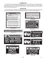
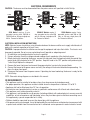
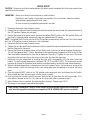
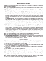
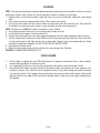
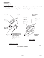
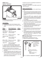
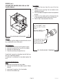
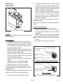
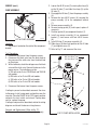
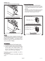
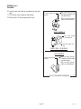
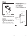
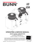
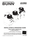
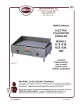
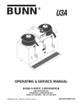
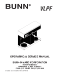
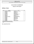
SRU
SRUA
OPERATING & SERVICE MANUAL
BUNN-O-MATIC CORPORATION
POST OFFICE BOX 3227
SPRINGFIELD, ILLINOIS 62708-3227
PHONE: (217) 529-6601 FAX: (217) 529-6644
To ensure you have the latest revision of the Operating Manual, or to view the Illustrated Parts
Catalog, Programming Manual, or Service Manual, please visit the Bunn-O-Matic website, at
www.bunn.com. This is absolutely FREE, and the quickest way to obtain the latest catalog and
manual updates. For Technical Service, contact Bunn-O-Matic Corporation at 1-800-286-6070.
10067.0000J 10/08 ©1981 Bunn-O-Matic Corporation
BUNN-O-MATIC COMMERCIAL PRODUCT WARRANTY
Bunn-O-Matic Corp. (“BUNN”) warrants equipment manufactured by it as follows:
1) All equipment other than as specified below: 2 years parts and 1 year labor.
2) Electronic circuit and/or control boards: parts and labor for 3 years.
3) Compressors on refrigeration equipment: 5 years parts and 1 year labor.
4) Grinding burrs on coffee grinding equipment to grind coffee to meet original factory screen sieve analysis:
parts and labor for 3 years or 30,000 pounds of coffee, whichever comes first.
These warranty periods run from the date of installation BUNN warrants that the equipment manufactured by
it will be commercially free of defects in material and workmanship existing at the time of manufacture and
appearing within the applicable warranty period. This warranty does not apply to any equipment, component or
part that was not manufactured by BUNN or that, in BUNN’s judgment, has been affected by misuse, neglect,
alteration, improper installation or operation, improper maintenance or repair, damage or casualty. This warranty is
conditioned on the Buyer 1) giving BUNN prompt notice of any claim to be made under this warranty by telephone
at (217) 529-6601 or by writing to Post Office Box 3227, Springfield, Illinois 62708-3227; 2) if requested by
BUNN, shipping the defective equipment prepaid to an authorized BUNN service location; and 3) receiving prior
authorization from BUNN that the defective equipment is under warranty.
THE FOREGOING WARRANTY IS EXCLUSIVE AND IS IN LIEU OF ANY OTHER WARRANTY, WRITTEN OR
ORAL, EXPRESS OR IMPLIED, INCLUDING, BUT NOT LIMITED TO, ANY IMPLIED WARRANTY OF EITHER
MERCHANTABILITY OR FITNESS FOR A PARTICULAR PURPOSE. The agents, dealers or employees of BUNN
are not authorized to make modifications to this warranty or to make additional warranties that are binding on
BUNN. Accordingly, statements by such individuals, whether oral or written, do not constitute warranties and
should not be relied upon.
If BUNN determines in its sole discretion that the equipment does not conform to the warranty, BUNN, at its
exclusive option while the equipment is under warranty, shall either 1) provide at no charge replacement parts
and/or labor (during the applicable parts and labor warranty periods specified above) to repair the defective
components, provided that this repair is done by a BUNN Authorized Service Representative; or 2) shall replace
the equipment or refund the purchase price for the equipment.
THE BUYER’S REMEDY AGAINST BUNN FOR THE BREACH OF ANY OBLIGATION ARISING OUT OF THE SALE OF
THIS EQUIPMENT, WHETHER DERIVED FROM WARRANTY OR OTHERWISE, SHALL BE LIMITED, AT BUNN’S
SOLE OPTION AS SPECIFIED HEREIN, TO REPAIR, REPLACEMENT OR REFUND.
In no event shall BUNN be liable for any other damage or loss, including, but not limited to, lost profits, lost sales,
loss of use of equipment, claims of Buyer’s customers, cost of capital, cost of down time, cost of substitute
equipment, facilities or services, or any other special, incidental or consequential damages.
BrewWISE, BrewLOGIC, BrewWIZARD, BUNN Gourmet Ice, BUNN Pour-O-Matic, BUNN, Bunn-OMatic, Bunn-O-Matic,
BUNNlink, BUNNserve, BUNN Espress, DBC, Dr. Brew, Dual, EasyClear, EasyGard, Easy Pour, FlavorGard, Gourmet Ice,
Gourmet Juice, High Intensity, IMIX, Infusion Series, Quality Beverage Equipment Worldwide, The Mark of Quality in Beverage Equipment Worldwide, My Café, PowerLogic, Safety-Fresh, Scale-Pro, Single, Smart Funnel, Smart Hopper, SmartWAVE, Soft Heat, SplashGard, System III, ThermoFresh, 392, AutoPOD, AXIOM, Beverage Profit Calculator, Beverage
Bar Creator, BrewMETER, BUNNSERVE, BUNNsource, Coffee At Its Best, Cool Froth, Digital Brewer Control, Intellisteam,
Nothing Brews Like a BUNN, Pouring Profits, Pulse Wave, Signature Series, Silver Series, Smart Heat, Tea At Its Best, The
Horizontal Red Line, Titan, Ultra, are either trademarks or registered trademarks of Bunn-O-Matic Corporation.
Page 2
10067 100908
INTRODUCTION
This brewer will brew a three gallon batch of coffee into the reservoir, which has its own dispensing faucet.
The brewer also has a hot water faucet for allied beverage use. It is only for indoor use on a sturdy counter
where ambient temperature is in the range of 10-30°C (50-85°F). Brewer to be installed at a location where it
can be overseen by trained personnel.
USER NOTICES
Carefully read and follow all notices on the brewer and in this manual. They were written for your protection.
All notices on the brewer are to be kept in good condition. Replace any unreadable or damaged labels.
WARNING
This equipment must be installed to comply
with the International Plumbing Code of the
International Code Council and the Food
Code Manual of the Food and Drug Administration (FDA). For models installed outside
the U.S.A., comply with the applicable
Plumbing /Sanitation Code.
Fill water tank before turning - on thermostat or connecting appliance
to power source.
Use only on a properly protected
circuit capable of the rated load.
Electrically ground the chassis.
Follow national/local electrical codes.
Do not use near combustibles.
#00656.0000
FAILURE TO COMPLY RISKS EQUIPMENT
DAMAGE, FIRE, OR SHOCK HAZARD
READ THE ENTIRE OPERATING MANUAL
BEFORE BUYING OR USING THIS PRODUCT
THIS APPLIANCE IS HEATED WHENEVER
CONNECTED TO A POWER SOURCE
00831.0000F 3/98 ©1998 BUNN-O-MATIC CORPORATION
#00831.0000
#37881.0000
ATTENTION: TURN OFF WHEN UNATTENDED
WARNING
#00878.0000
REMOVE FUNNEL
SLOWLY
WARNING
Very Hot Water
Use With Care!
#03408.0000
WARNING
H
O
T
LIQUID
#12593.0000
#03409.0000
CAUTION
HOT
SURFACES
#12555.0000
#29299.0000
Page 3
10067 011608
ELECTRICAL REQUIREMENTS
CAUTION - The brewer must be disconnected from the power source until specified in Initial Set-Up.
L2 RED
WHITE
NEUTRAL
BLACK
120V A.C.
208 OR
240V A.C.
RED
BLACK
L1
230V A.C.
L2
RED
L1
L2
208 OR
240V A.C.
120V A.C.
GREEN
GREEN
GREEN
GREEN
L1 BLACK
P1842
P1841
SRU Model requires 3-wire,
grounded service rated 120/208 or
120/240 volts ac, 30 amp, single phase,
60 Hz. Proceed as follows:
SRUA-CE Models require 2wire, grounded service rated 230
volts ac, 30 amp, single phase, 60
Hz. Proceed as follows:
P1842
SRUA Models require 2-wire,
grounded service rated 208 or 240
volts ac, 30 amp, single phase, 60
Hz. Proceed as follows:
ELECTRICAL INSTALLATION INSTRUCTIONS
NOTE: Electrical source should have a circuit breaker between the brewer and the main supply which breaks all
poles with a contact separation of at least 3 mm.
CAUTION – Improper electrical installation can damage the equipment and injure the installer. The chassis must
be properly grounded. Do not assume a plumbing line will provide an adequate ground.
1. An electrician must provide electrical service as specified.
2. Using a voltmeter, check the voltage and color coding of each conductor at the electrical source.
3. Before electrically connecting the brewer, remove the side panel from the hood and rotate the control thermostat knob fully clockwise to the "OFF" position. Keep this knob in the "OFF" position until performing the
"Initial Setup" Replace the side panel.
4. Remove the lower front panel and connect the proper electrical service to the terminal block.
5. Connect the brewer to the power source and verify the voltage at the terminal block before proceeding. Replace the lower front panel.
6. Disconnect the brewer from the power source. If plumbing has been hooked up, the brewer is ready for the
Initial Setup.
NOTE: Schematic wiring diagrams are included in this manual.
CE REQUIREMENTS
• This appliance must be installed in locations where it can be overseen by trained personnel.
• For proper operation, this appliance must be installed where the temperature is between 5°C to 35°C.
• Appliance shall not be tilted more than 10° for safe operation.
• An electrician must provide electrical service as specified in conformance with all local and national codes.
• This appliance must not be cleaned by water jet.
• This appliance is not intended for use by persons (including children) with reduced physical, sensory or mental
capabilities, or lack of experience and knowledge, unless they have been given instructions concerning use of
this appliance by a person responsible for its safety.
• Children should be supervised to ensure they do not play with the appliance.
• If the power cord is ever damaged, it must be replaced by the manufacturer or authorized service personnel with
a special cord available from the manufacturer or its authorized service personnel in order to avoid a hazard.
Page 4
10067 102808
PLUMBING REQUIREMENTS
These brewers must be connected to a cold water system with operating pressure between 20 and 90 psi
(138 and 621 kPa) from a 1/2" or larger supply line. A shut-off valve should be installed in the line before the
brewer. Install a regulator in the line when pressure is greater than 90 psi (621 kPa) to reduce it to 50 psi (345
kPa). The water inlet fitting is 3/8" flare.
NOTE - Bunn-O-Matic recommends 3/8" copper tubing for installations from the 1/2" water supply line. BunnO-Matic does not recommend the use of a saddle valve to install the brewer. The size and shape of the hole made
in the supply line by this type of device may restrict water flow.
Plumbing Hook-up
1. Make certain the 3/8" female flare fitting on the short tube from the outlet of strainer (supplied) is securely
attached to the male fitting at the bottom rear of the brewer.
2. Flush the water line and securely attach it to the 3/8" male flare fitting on the inlet of the strainer.
3. Turn on the water supply.
4. Inspect the connection for leaks.
This equipment must be installed to comply with the International Plumbing Code of the International
Code Council and the Food Code Manual of the Food and Drug Administration (FDA). For models
installed outside the U.S.A., you must comply with the applicable Plumbing/Sanitation Code for
your area.
Page 5
10067 011608
INITIAL SETUP
CAUTION - The brewer must be disconnected from the power source throughout the initial setup, except when
specified in the instructions.
IMPORTANT: Brewer must be level and installed on a sturdy structure.
Electrician's and Plumber's Instructions are provided. These instructions should be carefully followed before proceeding with initial setup.
Be sure all electrical and plumbing connections are tight.
1. Disconnect the brewer from the power source.
2. Remove the left side panel from the hood and rotate the control thermostat knob fully counterclockwise to
the "OFF" position. Replace the side panel.
3. Connect the brewer to the power source and place the lighted ON/OFF switch in the "ON" position. Water will
flow into the tank and should automatically stop after approximately 15 minutes.
NOTE - The lighted ON/OFF switch must be in the "ON" position to automatically refill the tank. The switch should
be in the "OFF" position whenever the brewer is left unattended.
4. Disconnect the brewer from the power source.
5. Remove the left side panel from the hood and rotate the control thermostat knob clockwise to the 5 o'clock
position. Replace the side panel.
6. Connect the brewer to the power source and wait for the water in the tank to heat to the proper temperature.
This will take approximately 1-2 hours, depending on the incoming water temperature. Some water will flow
from the overflow tube during this time due to expansion. Draw off a 1/2 gallon of water every 15 minutes
during the initial heat-up to lessen the chance of hot water flow from this expansion.
7. Determine the water temperature by checking the water with a thermometer at the hot water faucet (red
handle). The best brewing temperature is between 195˚ (91˚C) and 200˚F (93˚C). The temperature may be
increased by turning the thermostat knob clockwise and decreased by turning the knob counterclockwise.
8. When the desired temperature is attained, place the funnel support, funnel, and funnel cover on top of the
coffee reservoir. Center the discharge of the water swing spout over the opening in the top of the funnel
cover.
9. Place the lighted ON/OFF switch in the "ON" position and momentarily press and release the start switch.
Water should flow from the swing spout into the funnel assembly.
10.Drain and measure the water from the reservoir when the flow of water from this initial cycle stops. If it is
three gallons, proceed to step 12. If it is more or less than three gallons, proceed to step 11.
11.Adjust the brew timer as required. See Adjusting Brew Volumes. Repeat steps 9 & 10.
12. The brewer is now properly adjusted to brew coffee.
Bunn-O-Matic recommends a bead of silicon sealant be placed around the base on the countertop
after the initial operation instructions are completed. B.O.M. #M2509.1001 sealant is available.
Page 6
10067 011608
ADJUSTING BREW VOLUMES
CAUTION - Disconnect the power source from the brewer prior to the removal of any panel for the replacement
or adjustment of any component.
NOTE: Prior to setting or modifying batch sizes, check that the brewer is connected to water supply, the tank is
properly filled, and a funnel and server are in place.
1. Modifying batch sizes. To modify a batch volume, first check that the SET/LOCK switch is in the “SET” position on the circuit board.
To increase a batch size. Press and hold the START or BREW switch until you see three breaks in the water
stream from the swing arm. Release the switch (Failure to release the switch within two seconds after the
third break in the stream causes the volume setting to be aborted and previous volume setting will remain
in memory) and press it again one or more times. Each time the switch is pressed, two seconds are added
to the brew time period. Allow the brew cycle to finish in order to verify that the desired volume has been
achieved.
To decrease a batch size. Press and release the START or BREW switch once for every two-second interval
to be removed from the total brew time period; then immediately press and hold down the START or BREW
switch until you see three breaks in the water stream from the swing arm. Release the switch. (Failure to
release the switch within two seconds after the third break in the stream causes the volume setting to be
aborted and previous volume setting will remain in memory). Allow the brew cycle to finish in order to verify
that the desired volume has been achieved.
2. Setting batch sizes. To set a batch volume, first check that the SET/LOCK switch is in the “SET” position on
the circuit board. Press and hold the START or BREW switch until you see three breaks in the water stream
from the swing arm, and then release the switch. (Failure to release the switch within two seconds after the
third break in the stream causes the volume setting to be aborted and previous volume setting will remain in
memory). View the level of the liquid being dispensed. When the desired level is reached, turn the ON/OFF
switch to “OFF” (lower). The brewer remembers this volume and will continue to brew batches of this size
until the volume setting procedure is repeated.
NOTE: When brewing coffee, batch volumes will decrease due to absorption by the coffee grounds.
NOTE: HALF-BATCH AND FULL BATCH SETTINGS MUST EACH BE SET SEPARATELY
3. Setting programming disable feature. If it becomes necessary to prevent anyone from changing brew times
once programmed, you can set the SET/LOCK switch to the “LOCK” position. This will prevent any programming until switch is once again placed in the “SET” position.
COFFEE BREWING
1. Brewing cycles may be started whenever water temperature is correct. This condition is indicated by the dial
thermometer on front of the brewer. Whenever the pointer is in the green, brewer is ready for brewing.
2. Insert Bunn filter in funnel and add desired amount of coffee.
3. Level the bed of coffee and place funnel into the funnel support. Place funnel cover over the funnel and be
sure the water swing spout is over the center of the funnel cover.
4. Turn "ON/OFF" switch to the "ON" position.(This switch must be in the "ON" position to start and complete a
brewing cycle.)
5. Push and release "START" switch to start the brew cycle.
6. Water swing spout should not be moved as long as water is flowing into the funnel cover. When water stops
flowing, it may then be moved for access to brewing funnel.
7. Remove funnel cover. Funnel should not be removed from urn until drip out of coffee has been completed.
8. To empty funnel, invert it over a waste container to dispose of filter and grounds. An additional flange is
provided on the funnel to help make this step easier.
NOTE: Hot water may be drawn from the hot water faucet during a brew cycle. However, if a large amount of
hot water is drawn off (over 1 gallon) operator should wait to do so between brewing cycles.
Page 7
10067 080200
CLEANING
NOTE: Tank and tank components should be delimed regularly based on local water conditions. Excessive mineral
build up on stainless steel surfaces can initiate corrosion reactions resulting in serious leaks,
1. Remove funnel, funnel lid and support. Under hot water, rinse away all coffee oils. Wipe with a clean damp
cloth.
2. Drain coffee reservoir by opening coffee faucet. When empty, close faucet.
3. Cycle two or three inches of water into the coffee reservoir and scrub entire reservoir area. (Pour a bucket
of cracked ice in coffee reservoir to obtain a more desirable cleaning water temperature.)
NOTE: The brewer must NOT be rinsed or cleaned by a water jet device.
4. Drain coffee reservoir and rinse. Use clean damp cloth to wipe reservoir.
5. Install coffee funnel support, funnel and funnel lid.
6. Remove the sight gauge cap, insert sight gauge cleaning brush into the sight gauge glass tube and clean.
7. To clean coffee faucet, remove the faucet handle from the faucet and faucet clean out cap. Clean faucet with
a faucet cleaning brush and wipe all parts with a damp cloth. Replace faucet seat cup periodically if badly
stained or to stop faucet dripping. DO NOT CLEAN THE HOT WATER FAUCET.
8 Reassemble the coffee faucet.
9. Wipe the entire outside surface of the machine with a clean damp cloth. Wipe dry.
CAUTION - CLEANING SURFACES ARE HOT!!
FILTER HOLDER
1.
2.
3.
A filter holder is supplied with each SRU coffee brewer. Its purpose is to keep the filters in their originally
formed shape to properly fit the brewer funnel.
It is suggested that only one cluster of filters be placed in the holder at one time for best results.
Not using the filter holder may permit the filters to gradually widen out towards a flat shape, especially so if
humidity is present. Once a filter has lost its upright side walls, it may tend to collapse inward when placed
in the brewing funnel. If this happens the hot water spray may cause one side to fall inwards, letting coffee
grounds flow over the edge of filter and into the brewed coffee. Proper use of the holder should prevent
this problem.
Page 8
10067 081506
TROUBLESHOOTING
A troubleshooting guide is provided to suggest probable causes and remedies for the most likely problems
encountered. If the problem remains after exhausting the troubleshooting steps, contact the Bunn-O-Matic
Technical Service Department.
• Inspection, testing, and repair of electrical equipment should be performed only by qualified service personnel.
• All electronic components have 120 volt ac and low voltage dc potential on their terminals. Shorting of
terminals or the application of external voltages may result in board failure.
• Intermittent operation of electronic circuit boards is unlikely. Board failure will normally be permanent. If
an intermittent condition is encountered, the cause will likely be a switch contact or a loose connection at a
terminal or crimp.
• Solenoid removal requires interrupting the water supply to the valve. Damage may result if solenoids are
energized for more than ten minutes without a supply of water.
• The use of two wrenches is recommended whenever plumbing fittings are tightened or loosened. This will
help to avoid twists and kinks in the tubing.
• Make certain that all plumbing connections are sealed and electrical connections tight and isolated.
• This brewer is heated at all times. Keep away from combustibles.
WARNING –
•
•
•
•
Exercise extreme caution when servicing electrical equipment.
Unplug the brewer when servicing, except when electrical tests are specified.
Follow recommended service procedures
Replace all protective shields or safety notices
PROBLEM
PROBABLE CAUSE
REMEDY
Brew cycle will not start
1. No water
Water lines and valves to the brewer
must be open.
2. No power or incorrect voltage to
the brewer
(A1) Check the terminal block for
120 volts ac across the red and white
terminals and the black and white
terminal on three wire 102/208 volt
or 120/240 volt models.
(A2) Check the terminal block for 208
volts ac, 230 volts ac or 240 volts
ac on "A Series" brewers across the
red and black terminals on two wire
single phase 208 volt, 230 volt and
240 volt models.
(A3) Check the terminal block for 208
volts ac and 240 volts ac across
the black and blue terminals, the
blue and red and the black and red
terminals on three wire three phase
208 volt and 240 volt models.
(B) Check circuit breakers or
fuses.
Page 9
10067 040100
TROUBLESHOOTING (cont.)
PROBLEM
Brew cycle will not start (cont)
PROBABLE CAUSE
3. Water level below pump housing.
(Water level in the hot water gauge
glass should be approximately half
full).
REMEDY
Be sure water shut-off valve is open
and that the in-line filters or strainers
are not blocking water flow. (Do not
confuse water shut-off valve with the
manual fill and drain valve underneath
the brewer).
4. ON/OFF Switch
Refer to Service - ON/OFF Switch for
testing. See page 22
5. Start Switch
Refer to Service - Start Switches for
testing procedures. See page 28
6. Timer
Refer to Service - Timer for testing
procedures. See page 31 or 33
7. Pump
Refer to Service - Pump for testing
procedures. See page 24
8. Solenoid Valve
Refer to Service - Solenoid Valve for
testing procedures. See page 26
9. Strainer
(A) Direction of flow arrow must be
pointing towards brewer.
(B) Remove the strainer and check for
obstructions. Clear or replace.
Tank not filling
1. ON/OFF Switch (This switch must
be in the "ON" position for the refill
circuit to operate.
Refer to Service - ON/OFF Switch for
testing procedures. See page 23
2. No water
Be sure water shut-off is open and that
in-line filters or strainers are not blocking water flow. (Do not confuse water
shut-off valve with the manual fill and
drain valve underneath brewer).
3. Solenoid Valve
Refer to Service - Solenoid Valve for
testing procedures. See page 26
4. Probe
Refer to Service - Probe for testing
procedures. See page 21
5. Liquid Level Board
Refer to Service - Liquid Level Board
for testing procedures. See page 21
Page 10
10067 080200
TROUBLESHOOTING (cont.)
PROBLEM
Water running out of the overflow
Water is not hot
PROBABLE CAUSE
1. Brewer not level
REMEDY
Brewer must be level and installed
on a sturdy structure.
2. Solenoid Valve
Refer to Service - Solenoid Valve for
testing procedures. See page 26
3. Liquid Level Board
Refer to Service -Liquid Level Board
for testing procedures. See page
21
4. Probe
Refer to Service - Probe for testing
procedures. See page 21
1. Limit Thermostat
CAUTION - Do not eliminate or
bypass limit thermostat. Use only
Bunn-O-Matic replacement part
#29329.1000.
Refer to Service - Limit Thermostat
for testing procedures. See page
20
2. Control Thermostat
Refer to Service - Control Thermostat for testing procedures. See
page 18
3. Tank Heater(s)
Refer to Service - Tank Heater for
testing procedures. See page 29
4. Contactor
Refer to Service - Contactor for testing procedures. See page 16
Page 11
10067 080200
TROUBLESHOOTING (cont.)
PROBLEM
Circuit breaker keeps tripping
Water keeps running from swing
spout
Inconsistent coffee yield
Funnel overflows
PROBABLE CAUSE
1. Circuit Breaker
REMEDY
Refer to Service - Circuit Breaker for
testing procedures. See page 15
2. ON/OFF Switch
Refer to Service - ON/OFF Switch for
testing procedures. See page 23
3. Brew Circuit
Refer to Service - Pump Assembly for
testing procedures. See page 24
4. Refill Circuit
Refer to Service - Liquid Level
Board for testing procedures. See
page 21
1. Timer
Refer to Service - Timer for testing
procedures. See page 31 or 33
2. Start Switch
Refer to Service - Start Switch for
testing procedures. See page 29
1. Timer
Refer to Service - Timer for testing
procedures. See page 31 or 33
2. Solenoid Valve
Refer to Service - Solenoid Valve for
testing procedures. See page 26
3. Lime build-up in swing spout and
pump tubing.
Remove swing spout and insert
deliming rod down into pump tubing
as far as possible.
1. Filters
Use Bunn® filters made for the SRU
brewer.
2. Hole in bottom of funnel
obstructed.
Remove obstruction.
3. Pump - Flow Rate
Check pump flow rate with a watch.
Pump flow rate should be approximately 24 ounces in 15 seconds. Be
sure pump assembly is free of any
obstructions.
Page 12
10067 080200
TROUBLESHOOTING (cont.)
PROBLEM
PROBABLE CAUSE
REMEDY
Funnel overflows (cont.)
4. Soft Water
When using a water softener, a
coarse grind of coffee may be preferred. If required, a bypass system
is available as an optional feature.
Coffee reservoir overflows
1. Coffee reservoir not completely
empty before a brew cycle was
started.
Be sure coffee reservoir is empty
before brew cycle is started.
2. Timer
Refer to Service -Timer for testing
procedures. See page 31 or 33
3. Pump - Flow Rate
Check pump flow rate with a watch.
Pump flow rate should be approximately 24 ounces in 15 seconds. Be
sure pump assembly is free of any
obstructions.
1. Solenoid Valve
The nut on the solenoid must be tight
or it will vibrate during operation.
2. Plumbing lines
Plumbing lines should not be resting
on the counter top.
3. Water supply
(A) The brewer must be connected
to a cold water line.
Brewer is making unusal noises
(B) Water pressure to the brewer
must not exceed 90 psi (621 kPa).
Install a regulator if necessary to
lower the pressure to approximately
50 psi (345 kPa).
4. Tank Heater(s)
Page 13
Remove and clean lime off the tank
heater. See page 29
10067 080200
SERVICE
This section provides procedures for testing and
replacing various major components used in this
brewer should service become necessary. Refer to
Troubleshooting for assistance in determining the
cause of any problem.
WARNING - Inspection, testing, and repair of electrical equipment should be performed only by qualified
service personnel. The brewer should be unplugged
when servicing, except when electrical tests are required and the test procedure specifically states to
plug in the brewer.
COMPONENT ACCESS
WARNING - Disconnect the brewer from the power
source before the removal of any panel or the replacement of any component.
Contents
Circuit Breaker ......................................................15
Contactor...............................................................16
Control Thermostat................................................18
Fuse and Fuse Holder . ..........................................19
Limit Thermostat....................................................20
Liquid Level Board and Level Probe . ................... 21
ON/OFF Switch.......................................................23
Pump.....................................................................24
Selector Switch (Half Batch)..................................25
Solenoid . ..............................................................26
Start Switch (Brew)................................................27
Tank Heater............................................................29
Thermal Cut-off . .................................................. 30
Timer (Early Models).............................................31
Digital Brew Timer (Late Models)...........................33
Master ON/OFF Switch (Late Models)....................35
Wiring Diagrams....................................... 36 thru 38
The control thermostat, limit thermostat, pump,
solenoid valve, liquid level probe and tank heater are
accessible by removal of the swing spout, front cupola
cover, rear cupola cover and the cupola.
Disconnect the swing spout nut from the swing
spout base fitting. Remove swing spout.
Remove the four #8-32 screws, two on each side,
securing the side covers to the cupola.
Slip cupola off of the component bracket.
The on/off switch, selector switch, start switch,
timer, contactor and liquid level control board are accessible by removal of the front lower panel.
Remove the four #8-32 screws securing the front
access panel to the base.
FIG. 1 COMPONENT ACCESS
P2053.25
The circuit breaker, fuse and fuse holder are accessible by removal of the rear utility cover.
Remove the six #8-32 screws securing the rear
utility cover to the housing.
Page 14
10067 080200
SERVICE (cont.)
CIRCUIT BREAKER (120/208V and 120/240V Three
Wire Models)
FIG. 2 CIRCUIT BREAKER
If continuity is not present as described, press the reset
button and repeat step 5, if continuity is not present
as described, replace the circuit breaker.
Removal and Replacement:
1. Remove wires from the circuit breaker.
2. Remove the nut securing the circuit breaker to the
component bracket.
3. Remove circuit breaker and discard.
4. Install new circuit breaker on component bracket
and secure with nut.
5. Refer to Fig. 3 and reconnect the wires.
P2115.30
Location:
The circuit breaker is located on the rear of the
urn, behind the rear utility cover.
Test Procedures:
1. Disconnect the brewer from the power source.
2. Disconnect the black wire from the main harness
from the circuit breaker and the white wire on the
pump assembly. With a voltmeter, check the voltage
across the black wire and the white wire. Connect
the brewer to the power source. The indication
must be 120 volts for 120/208 and 120/240 volt,
3-wire with ground, single phase.
3. Disconnect the brewer from the power source.
BLK from Main
Harness
BLK from ON/
OFF Switch
FIG. 3 CIRCUIT BREAKER TERMINALS
P1723
If voltage is present as described, reconnect the white
wire to the pump assembly and proceed to #4. If voltage is not present as described, refer to the Wiring
Diagrams and check the brewer wiring harness.
4. With the black wire removed, remove the other
black wire from the circuit breaker.
5. Check for continuity across the terminals on the
circuit breaker.
Page 15
10067 040100
SERVICE (cont.)
CONTACTOR
5. Disconnect the brewer from the power source.
If voltage is present as described, proceed to #6.
If voltage is not present as described refer to the Wiring
Diagrams and check the brewer wiring harness.
6. Check for continuity between the black leads on
the contactor coil or the left and right terminals
on the contactor coil on 230 volt models.
If continuity is present as described, reconnect the
wires and proceed to #7.
If continuity is not present as described, replace the
contactor.
FIG. 4 CONTACTOR
P2208.40
Location:
The contactor is located inside the front lower access panel, left of center on the component bracket.
Test Procedures:
1. Disconnect the brewer from the power source.
2A.120/208V and 120/240V THREE WIRE MODELS
Disconnect the black wire from the contactor coil
to the limit thermostat and black wire from the
white wire on the main harness.
2B.208V or 240V TWO WIRE MODELS, 208V and
240V THREE WIRE MODELS
Disconnect the black wire from the contactor coil
to the limit thermostat and black wire from the red
wire on the main harness.
2C.230V MODELS
Disconnect the red wire from contactor coil to the
limit thermostat and the black wire from the main
harness.
3. Connect the brewer to the power source.
4. Check the voltage across the limit wire and the
wire from the the main harness.The indication
must be:
a) 120 volts for 120/208 and 120/240 volt, 3-wire
with ground, single phase;
b) 230 volts for 230 volt, 2-wire with ground, single
phase;
c) 208 volts for 208 volt, 2-wire with ground, single
phase;
d) 240 volts for 240 volt, 2-wire with ground, single
phase.
7. On all brewers check the voltage across the upper
left terminal and the upper right terminal on the
contactor with a voltmeter. Connect the brewer to
the power source. The indication must be:
a) 120 volts for 120/208 and 120/240 volt, 3-wire
with ground, single phase;
b) 230 volts for 230 volt, 2-wire with ground, single
phase;
c) 208 volts for 208 volt, 2-wire with ground, single
phase;
d) 240 volts for 240 volt, 2-wire with ground, single
phase.
8. Disconnect the brewer from the power source.
If voltage is present as described, proceed to #9.
If voltage is not present as described, refer to the wiring
diagrams and check the brewer wiring harness.
9. Check for continuity across the terminals on the
left side of the contactor by manually closing the
contacts. Continuity must not be present when the
contact is released.
10.Check for continuity across the terminals on the
right side of the contactor by manually closing the
contacts. Continuity must not be present when the
contact is released.
If continuity is present as described, the contactor is
operating properly.
If continuity is not present as described, replace the
contactor.
Page 16
10067 040100
SERVICE (cont.)
CONTACTOR (cont.)
Removal and Replacement:
1. Disconnect all the wires from the contactor.
2. Remove the two #8-32 screws securing the
contactor to the contactor mounting bracket.
BLK to Terminal
Block (L1)
3. Install new contactor and secure with two #8-32
screws.
4. Refer to Fig. 5 and reconnect the wires.
RED to Terminal
Block(L2)
BLK to Terminal
Block (L1)
BLK to Terminal
Block (L2)
BLK to Tank
Heater (L1)
BLK Thermal
Fuse to Tank
Heater
RED Thermal
Fuse to Tank
Heater
RED to Tank
Heater (L2)
BLK to Limit
Thermostat
WHI from Main Harness
(120/208V and 120/240V
Three Wire Models)
RED from Main Harness
(208V, 240V Two Wire
Models)
RED to Terminal
Block (L2)
RED to Limit
Thermostat
230V - CE Models
120/208V, 120/240V, 208V,
240V MODELS
FIG.5 CONTACTOR TERMINALS
Page 17
P1725.50
10067 040100
If continuity is present as described, the control thermostat is operating properly.
If continuity is not present as described, replace the
control thermostat.
SERVICE (cont.)
CONTROL THERMOSTAT
FIG. 6 CONTROL THERMOSTAT
P2113.40
Location:
The control thermostat is mounted on the left front
of the top component bracket.
Test Procedures:
1. Disconnect the brewer from the power source.
2. Locate the thermostat and the voltage check
points.
Model
120/208V &
120/240V - 3wire w/ground
single phase
Check Voltage Across
Voltage
Black wire on therostat 120V
from main
harness to white wire
in terminal block.
230V - 2-wire Red wire on thermow/ground single stat from main
harness to black wire
phase
in terminal block.
230V
Removal and Replacement:
1. Disconnect the wires from the control thermostat.
2. Remove the thermostat capillary bulb by firmly pulling up on the capillary at the component bracket. This
will disengage the grommet from the component
bracket.
3. Remove the #8-32 screw securing the control
thermostat and mounting bracket to the component
bracket. Remove control thermostat and bracket as
an assembly.
4. Remove knob from control thermostat.
5. Remove the two #6-32 screws securing the control
thermostat to the thermostat mounting bracket.
Remove and discard thermostat.
6. Install new control thermostat on thermostat mounting bracket and secure with two #6-32 screw.
7. Install knob on thermostat.
8. Install thermostat and mounting bracket on the
component bracket and secure with one #8-32
screw.
9. Carefully bend the capillary tube so that the tube and
bulb inside the brewer are in the vertical position.
The tube should extend an additional 5.5", above
the bulb into the brewer.
NOTE: The capillary tube must be clear of any electrical
termination and not kinked.
10.Refer to Fig. 7 and reconnect the wires.
11.Adjust the control thermostat as required.
208V or
208V or 240V - Black wire on thermo240V
2-wire w/ground stat from main
harness to red wire in
single phase
the terminal block.
4. Disconnect the brewer from the power source.
If voltage is present as described, proceed to #5.
If voltage is not present as described, refer to the wiring
diagrams and check the brewer wiring harness.
5. Disconnect the black or red wires from the control
thermostat.
6. Check for continuity across the terminals on the
control thermostat with the control thermostat in
the "ON" position (fully clockwise), continuity must
not be present when the thermostat is in the "OFF"
position (fully counterclockwise).
Page 18
BLK from Main Harness (All Models Except 230V CE Models
RED from Main
Harness (230V CE
Models)
BLK to Limit Thermostat
(All Models Except 230V CE
Models
RED to Limit Thermostat
(230V CE Models)
P1730
FIG. 7 CONTROL THERMOSTAT TERMINALS
10067 040100
SERVICE (cont.)
FUSE AND FUSE HOLDER (208V, 240V and 230V
Two Wire Models)
Fuse Holder:
1. Disconnect the wires from the rear of the fuse
holder.
2. Remove the nut securing the fuse holder to the
component bracket.
3. Push fuse holder through the hole in the component
bracket.
4. Install new fuse holder and fuse through the hole
in the component bracket and secure with nut.
5. Refer to Fig. 9 and reconnect the wires.
BLK from ON/OFF Switch
(208V and 240V Two Wire
Models)
RED from ON/OFF Switch
(230V Two Wire Models)
P2122.30
FIG.8 FUSE AND FUSE HOLDER
Location:
The fuse and fuse holder are located on the rear of
the urn behind the rear utility cover.
Test Procedures:
1. Disconnect the brewer from the power source.
2. Remove the cap and fuse from the fuse holder.
3. Remove fuse from the cap.
4. Check for continuity through the fuse.
BLK from Main Harness (208V
and 240V Two Wire Models)
RED from Main Harness
(230V Two Wire Models)
FIG. 9 FUSE HOLDER TERMINALS
P2112
If continuity is present as described, reinstall the fuse,
the fuse is operating properly.
If continuity is not present as described replace the
fuse.
Removal and Replacement:
Fuse:
1. Remove the cap from the fuse holder.
2. Remove fuse from the fuse holder, inspect, if blown
discard.
3. Install new 5 amp fuse in the fuse holder.
4. Reinstall fuse holder cap.
Page 19
10067 040100
SERVICE (cont.)
LIMIT THERMOSTAT
BLK to Contactor
coil (All Models
Except 230V CE
Models)
Red to Contactor Coil (230V CE
Models)
BLK to Control
Thermostat(All
Models Except
230V CE Models)
RED to Control
Thermostat (230V
CE Models)
P1984
FIG. 10 LIMIT THERMOSTAT
FIG. 11 LIMIT THERMOSTAT TERMINALS
P1732
Location:
The limit thermostat is located on the center rear
of the component bracket behind the tank heater.
Test Procedures:
1. Disconnect the brewer from the power source.
2. Disconnect the black wires or the red wires from
the limit thermostat.
3. Check for continuity across the limit thermostat
terminals with an ohmmeter.
If continuity is present as described, the limit thermostat
is operating properly.
If continuity is not present as described, replace the
limit thermostat.
Removal and Replacement:
1. Remove the wires from the limit thermostat terminals.
2. Carefully slide the limit thermostat out from under the
retaining clip and remove the limit thermostat.
3. Carefully slide the new limit thermostat into the
retaining clip.
4. Refer to Fig. 11 and reconnect the wires.
Page 20
10067 040100
SERVICE (cont.)
LIQUID LEVEL BOARD AND LEVEL PROBE
FIG.12 LIQUID LEVEL BOARD AND
LEVEL PROBE
Location:
5. Reconnect the blue wire to T1 on the liquid level
board.
6. Carefully connect a piece of insulated jumper wire
to T4. Keep the other end of this wire away from
any metal surface of the brewer.
7. Touching the free end of the jumper to the brewer's
frame simulates a "FULL" condition, preventing
jumper from touching the brewer's frame simulates
"NEED WATER" condition. Connect the brewer to
the power source, simulate the conditions in the
chart below while measuring the voltage between
T1 and T3 0n the liquid level board. Repeat these
several times. Keep in mind there is an approximate
five second delay for output to stabilize.
P2208.40
Model
The liquid level board is located behind the lower
front access panel, to the right of center on the component bracket. The level probe is located on the right
front of the upper component bracket.
Test Procedures:
1. Disconnect the brewer from the power source.
2. Disconnect the blue wire (T1) and the pink wire
(T4).
3. Check the voltage across terminals (T2) and (T3)
with the ON/OFF switch in the "ON" position. The
indication must be:
a) 120 volts for 120/208 and 120/240 volt, 3-wire
with ground, single phase;
b) 230 volts for 230 volt, 2-wire with ground, single
phase;
c) 208 volts for 208 volt, 2-wire with ground, single
phase;
d) 240 volts for 240 volt, 2-wire with ground, single
phase.
Voltage Jumper
Not Touching
Frame
Voltage Jumper
Touching
Frame
120/208V &
120/240V - 3wire w/ground
single phase
120V
0
230V - 2-wire
w/ground single
phase
230V
0
208V or 240V 2-wire w/ground
single phase
208V or
240V
0
0
4. Disconnect the brewer from the power source.
If voltage is present as described, proceed to #5.
If voltage is not present as described, refer to wiring
diagrams and check the brewer wiring harness.
Page 21
10067 040100
SERVICE (cont.)
LIQUID LEVEL BOARD AND LEVEL PROBE (cont.)
8. Disconnect the brewer from the power source and
remove the jumper wire from T4.
If voltage is present as described, liquid level board is
operating properly, proceed to #9.
If voltage is not present as described, replace the liquid
level board.
9. Reconnect the pink wire to T4.
10.Remove the two #8-32 screws securing the level
probe to the component bracket.
11.Gently pull the probe out of the component bracket
and inspect for corrosion. Replace if necessary.
12 Place the probe so that neither end is in contact
with any metal surface of the brewer.
13.Connect the brewer to the power source. Check
the voltage across T1 and T3, refer to chart below.
Keep in mind there is an approximate delay of five
seconds for output to stabilize.
Voltage Voltage Model
Jumper
Jumper
Touching
Not Touching
Frame
Frame
120/208V &
120/240V - 3wire w/ground
single phase
120V
230V - 2-wire
w/ground
single phase
230V
208V or 240V - 208V or
2-wire w/ground 240V
single phase
14.Disconnect the brewer from the power source.
If voltage is present as described, reinstall the level
probe, the liquid level board and level probe are operating properly.
If voltage is not present as described, check the pink wire
on the level probe from liquid level board terminal.
Removal and Replacement:
1. Remove all wires from the liquid level board.
2. Remove the #10-32 screw and flat washer securing
the protective shield to the component bracket.
3. Remove the #10-32 screw and internal tooth
lockwasher securing the liquid level board to the
component bracket.
4. Remove liquid level board and discard.
5. Install new liquid level board on component bracket
and secure with a #10-32 screw and internal tooth
lockwasher.
6. Install protective shield and secure with #10-32
screw and flat washer.
7. Refer to Fig. 13 and reconnect the wires.
T1 BLU to Solenoid Valve
0
T2 BLK to ON/OFF Switch (All models
except 230V-CE models- RED on CE
Models)
T3 WHI to Main Harness
(120/208V and120/240V
models)
T3 RED to Main Harness
(208V, 240V single phase and
three phase models)
T3 BLK to Main Harness
(230V two wire models)
0
0
0
T4 PIN to Level Probe
P1733
FIG.13 LIQUID LEVEL BOARD TERMINALS
Page 22
10067 040100
SERVICE (cont.)
ON/OFF SWITCH
6. a) 120/208V, 120/240V, 208V and 240V Models
- Check for continuity across the terminals on the
rear of the switch with the switch in the "ON" (upper)
position. Continuity must not be present when the
switch is in the "OFF" (lower) position.
b) 230V - CE Models - Check for continuity across
the center terminal (2) and the lower terminal (1)
when the switch is in the "ON" (upper) position.
Continuity must not present when the switch is in
"OFF" (lower) position.
If continuity is present as described, the switch is
operating properly.
If continuity is not present as described, replace the
switch.
P2053.25
FIG.14 ON/OFF SWITCH
Location:
The ON/OFF switch is located on the left side of the
lower front panel.
Test Procedures:
1. Disconnect the brewer from the power source.
2. a)120/208V, 120/240V, 208V and 240V Models
Remove the black wire on the ON/OFF switch from
the fuse holder or circuit breaker and the red wire
on the switch indicator light.
b) 230V - CE Models - Remove the red wire on the
ON/OFF switch from the fuse holder and the black
wire on the switch indicator light.
3. Connect the brewer to the power source. With a
voltmeter, check the voltage across the removed
wire. The indication must be:
a) 120 volts ac for 120/208 volt and 120/240 volt
models.
b) 208 volts ac for 2-wire 208 volt models.
c) 240 volts ac for 2-wire 240 volt models.
d) 230 volts ac for 2-wire 230 volt models.
4. Disconnect the brewer from the power source.
If voltage is present as described, reconnect the wires
and proceed to #5
If voltage is not present as described, refer to the wiring
diagrams and check the brewer wiring harness.
Removal and Replacement:
1. Remove the wires from the switch terminals.
2. Compress the clips on the back side of the switch
mounting bracket and gently push them through
the opening.
3. Push the new switch into the opening and spread
the clips to hold switch in the mounting bracket.
NOTE: ON 230V - CE models terminal (3) must be on
the top.
4. Refer to Fig. 15 and reconnect the wires.
BLK to On/Off Switch
BLK to Liquid Level Board L2
BLK to On/Off Switch BLK
to Start Switch
BLK to Circuit Breaker
or Fuse
Step #6
WHI or RED to Indicator
Light
120/208V, 120/240V, 208V and 240V MODELS
BLK from Indicator Light
RED to Fuse
Step #6
RED to Start Switch, Brew Timer
& Liquid Level Board
230V - CE Models
FIG. 15 ON/OFF SWITCH TERMINALS
5. Disconnect the wires on the ON/OFF switch.
Page 23
P2120.50
10067 040100
SERVICE (cont.)
PUMP ASSEMBLY
FIG.16 PUMP ASSEMBLY
P2113.40
Location:
The pump is located on the right of the component
bracket.
2. Loosen the #8-32 screw (2) securing the clamp (3)
on the fill tube (1) and slide the clamp (3) up the
fill tube (1).
3. Disengage the fill tube (1) from the pump assembly
(4).
4. Remove the four #8-32 screws (6) securing the
pump assembly (4) to the component bracket
(7).
5. Remove pump assembly (4).
6. Remove pump gasket (5) and inspect, replace if
necessary.
7. Position gasket (5) on component bracket (7).
8. Install new pump assembly (4) on component
bracket (7) and secure with four #8-32 screws
(6).
9. Install fill tube (1) on pump assembly (4).
10.Slide clamp (3) down into position on the fill tube
(1) and tighten screw (2).
11.Refer to Fig. 17 and reconnect the wires.
Test Procedures:
1. Disconnect the brewer from the power source.
2. Disconnect the black wire from the black lead on
the pump and the white wire from the black lead
on the pump.
3. With a voltmeter, check the voltage across the black
wire and the white wire. Connect the brewer to the
power source. The indication must be:
a) 120 volts ac for 3-wire 120/208 volt and 120/240
volt models.
b) 208 volts ac for 2-wire 208 volt models.
c) 240 volts ac for 2-wire 240 volt models.
d) 230 volts ac for 2-wire 230 volt models.
4. Disconnect the brewer from the power source.
WHI from Brew Timer
BLK from Brew Timer
1
2
3
6
4
5
7
If voltage is present as described, reconnect the wires
to the pump. Install swing spout and position over the
reservoir. Place the ON/OFF in the "ON" (upper) position
and push the start switch and release. If pump does
not run, replace the pump.
If voltage is not present as described, refer to the wiring
diagrams and check the brewer wiring harness.
Removal and Replacement (Refer to Fig. 17):
1. Disconnect the wires from the pump assembly.
FIG.17 PUMP INSTALLATION
Page 24
P1737
10067 040100
SERVICE (cont.)
SELECTOR SWITCH (HALF BATCH OPTION)
Removal and Replacement:
1. Remove the wires from the switch terminals.
2. Compress the clips on the back side of the switch
mounting panel and gently push them through the
opening.
3. Push the new switch into the opening and spread
the clips to hold switch in the mounting panel.
4. Refer to Fig. 19 and reconnect the wires.
P2053.25
GRY to Brew Timer
ALL MODELS EXCEPT 230V CE MODELS
PNK to Brew Timer
ALL MODELS EXCEPT 230V - CE MODELS
GRY to Brew Timer
PNK to Brew Timer
P2117.25
230V CE MODELS
FIG. 18 SELECTOR SWITCH (HALF BATCH)
Location:
230V - CE MODELS
FIG.19 SELECTOR SWITCH TERMINALS
P2118.60
The selector switch is located in the center of the
front access panel at the base of the urn on all models
except the 230V CE Models. The selector switch is
located to the right of the front panel, above the start
switch on the 230V CE Models.
Test Procedures:
1. Disconnect the brewer from the power source.
2. Disconnect the wires from the switch terminals.
3. Check for continuity across the switch terminals
with the switch in the "CLOSED" (bottom - half)
position. Continuity must not be present when the
switch is in the "OPEN" (top - full) position.
If continuity is present as described, the switch is
operating properly.
If continuity is not present as described, replace the
switch.
Page 25
10067 040100
SERVICE (cont.)
3. Disconnect the brewer from the power source.
SOLENOID
If voltage is present as described, proceed to #4.
If voltage is not present as described, refer to the brewer
wiring diagrams and check the wiring harness.
4. Disconnect the blue wire and the white wire, the
blue wire and the red wire or blue wire and black
wire from the solenoid terminals.
5. Check for continuity across the solenoid valve coil
terminals.
FIG. 20 SOLENOID
If continuity is present as described, reconnect the
wires to the solenoid.
If continuity is not present as described, replace the
solenoid valve.
P2113.40
Location:
The solenoid is mounted on the upper left rear of
the component bracket.
Test Procedures:
1. Disconnect the brewer from the power source.
2. A) For 120/208 volt and 120/240 volt 3-wire, single
phase models, disconnect the black wire from the
liquid level board #2 and the white wire on the
solenoid. Check the voltage across the black and
the white wire with a voltmeter. Connect the brewer
to the power source. The indication must be:
a) 208 volts ac for 3-wire 120/208 volt models.
b) 240 volts ac for 3-wire 120/240 volt models.
B) For 208 volt, 240 volt 2-wire single phase models, disconnect the black wire from the liquid level
board #2 and the red wire from the solenoid. With
a voltmeter check the voltage across the black and
red wires. Connect the brewer to the power source.
The indication must be:
a) 208 volts ac for 208 volt, 2-wire single phase
models.
b) 240 volts ac for 240 volt, 2-wire single phase
models.
C) For 230 volt - CE 2-wire single phase models,
disconnect the red wire from the liquid level board
#2 and the black wire from the solenoid. Check
the voltage across the red wire and the black wire
with a voltmeter. Connect the brewer to the power
source. The indication must be 230 volts ac.
6. Check the solenoid valve for coil action. Connect
the dispenser to the power source. Listen carefully
in the vicinity of the solenoid valve for a "clicking"
sound as the coil magnet attracts.
If the sound is heard as described and water will not
pass through the solenoid valve, there may be a blockage in the water line before the solenoid valve or, the
solenoid valve may require inspection for wear, and
removal of waterborne particles.
If the sound is not heard as described, replace the
solenoid valve.
Removal and Replacement:
1. Remove the wires from the solenoid valve.
2. Turn off the water supply to the dispenser.
3. Disconnect the water inlet line from the connector
on the solenoid valve.
4. Remove the #10-32 screws and the flat washers
securing the solenoid to the component bracket.
5. Remove solenoid, connectors, air chamber and
tank inlet tube as an assembly.
6. Remove the tank inlet tube grommet and discard.
7. Install new tank inlet tube grommet.
8. Install new solenoid assembly.
9. Install and secure solenoid assembly to the component bracket with a two #10-32 screws and flat
washers.
Page 26
10067 040100
SERVICE (cont.)
SOLENOID
10.Install water inlet tube to connector on the solenoid.
11.Turn on the water supply to the brewer.
12.Refer to Fig. 21 and reconnect the wires.
BLU from Liquid Level
Board #1
WHI from Main Harness
(120/208V, 120/240V, 380V
and 440V Models)
RED from Main Harness
(208V and 240V Models)
EARLY MODELS
BLU from Liquid
Level Board #1
BLK from Main Harness
EARLY 230V - CE MODELS
LATE MODELS
BLU from Liquid Level
Board #1
WHI from Main Harness
(120/208V, 120/240V, 380V
and 440V Models)
RED from Main Harness
(208V and 240V Models)
FIG. 21 SOLENOID TERMINALS
Page 27
P1741
10067 081506
SERVICE (cont.)
START SWITCH (BREW)
Test Procedures:
1. Disconnect the brewer from the power source.
2. Remove the wires from the start switch terminals.
3. Check for continuity across the switch terminals
when the switch is held in the lower position.
Continuity must not be present when the switch
is in the upper position.
If continuity is present as described, reconnect the
wires the switch is operating properly.
If continuity is not present as described, replace the
switch.
P2053.25
ALL MODELS EXCEPT 230V - CE MODELS
Removal and Replacement:
1. Remove the wires from the switch terminals.
2. Compress the clips on the back side of the switch
mounting panel and gently push them through the
opening.
3. Push the new switch into the opening and spread
the clips to hold switch in the mounting panel.
4. Refer to Fig. 23 and reconnect the wires.
BLU to Brew Timer
BLK from ON/OFF Switch
230V - CE MODELS
FIG. 22 START SWITCH (BREW)
ALL MODELS EXCEPT 230V - CE MODELS
Location:
The brew start switch is located on the lower right
side of the front access panel at the base of the urn
on all models except 230 volt CE. On 230 volt CE
models, the start switch is located on the lower right of
the front access panel, beneath the selector switch.
BLU to Brew Timer
RED from ON/OFF
Switch
230V - CE MODELS
P2119.65
FIG.23 BREW START SWITCH TERMINALS
Page 28
10067 040100
SERVICE (cont.)
TANK HEATERS
Removal and Replacement:
1. Remove the wires or thermal fuses from the tank
heater.
2. Remove the four #8-32 screws securing the tank
heater to the component bracket.
3. Remove tank heater and gasket.
4. Position new tank heater and gasket on the component bracket and secure with four #8-32 screws.
5. Refer to Fig. 25 and reconnect the wires.
RED to Contactor T2
(120/208V, 120/240 Three
Wire Single Phase, 208V
and 240V Two Wire, Single
Phase)
FIG. 24 TANK HEATER
P2113.40
RED (Thermal Fuse) to T2
(230V-CE Models)
Location:
The tank heater is located on the front center of the
upper component bracket.
Test Procedures:
1. Disconnect the brewer from the power source.
2. Disconnect the wires from the tank heater.
3. Check for continuity across the tank heater terminals.
BLK to Contactor T1 (All
Models Except 230V-CE
Models)
BLK (Thermal Fuse) to T1
(230V-CE Models)
If continuity is present as described, proceed to #4.
If continuity is not present as described, replace the
tank heater.
P1746
FIG. 25 TANK HEATER TERMINALS
Page 29
10067 040100
SERVICE (cont.)
THERMAL FUSES (230V-CE MODELS ONLY)
FIG. 26 THERMAL FUSES
P2121.40
Location:
The thermal fuses are mounted on the tank heater
terminals.
Test Procedures:
1. Disconnect the brewer from the power source.
2. Disconnect the thermal fuse from the tank heater
terminal and the contactor lead.
3. Check for continuity across the terminals on the
ends of the thermal fuse.
If continuity is present as described, the thermal fuse
is operating properly.
If continuity is not present as described, replace the
thermal fuse.
Removal and Replacement:
1. Disconnect the thermal fuse from the tank heater
terminal and the contactor lead and discard.
2. Connect the new thermal fuse to the tank heater
terminal and the contactor terminal.
Page 30
10067 040100
SERVICE (cont.)
4. Disconnect the brewer from the power source.
TIMER (Early Models)
If voltage is present as described, proceed to #5.
If voltage is not present as described, refer to the wiring
diagrams and check the brewer wiring harness.
5. With a voltmeter check the voltage across the sockets
P1 (BLU) and P2 (see chart in #3) of the female
connector on the main harness when the "ON/OFF"
switch is in the "ON" (upper) position and the start
switch pressed. Connect the brewer to the power
source. The indication must be:
a) 120 volts ac for 3-wire 120/208 volt and 120/240
volt models.
b) 208 volts ac for 2-wire 208 volt models.
c) 240 volts ac for 2-wire 240 volt models.
d) 230 volts ac for 2-wire 230 volt CE models.
6. Disconnect the brewer from the power source.
7. Reconnect the three pin connector from the main
wiring harness to the connector on the timer.
EARLY MODELS
FIG. 27 TIMER
P2114.40
Location:
The timer is located behind the front access panel
on the right side of the component bracket.
Test Procedures:
1. Disconnect the brewer from the power source.
2. Disconnect the polarized, three pin connector from
the brewer main harness and rotate the brew timer
dial fully counterclockwise.
3. With a voltmeter check the voltage across sockets
P2 and P3 (white and black wire or red wire) of the
female connector on the main wiring harness when
the "ON/OFF" switch is in the "ON" (upper) position.
See chart below for P2 and P3 wires:
MODEL
SRU-CE
SRUA
SRU
P2
BLK
RED
WHI
P3
RED
BLK
BLK
Connect the brewer to the power source. The indication must be:
a) 120 volts ac for 3-wire 120/208 volt and 120/240
volt models.
b) 208 volts ac for 2-wire 208 volt models.
c) 240 volts ac for 2-wire 240 volt models.
d) 230 volts ac for 2- wire 230 volt CE models.
If voltage is present as described, proceed to #8.
If voltage is not present as described, refer to the wiring
diagrams and check the brewer wiring harness.
8. Disconnect the black and white wires to the
pump.
9. With a voltmeter check the voltage across the black
and white wires when the "ON/OFF" switch is in the
"ON" (upper) position and the start switch pressed to
the start position and released. Connect the brewer
to the power source. The indication must be:
a) 120 volts ac for 3-wire 120/208 volt and 120/240
volt models.
b) 208 volts ac for 2-wire 208 volt models.
c) 240 volts ac for 2-wire 240 volt models.
d) 230 volts ac for 2-wire 230 volt CE models.
If is present as described, the brew timer is operating
properly. Reset the timer dial as required, to obtain the
desired brew volume.
If voltage is not present as described, replace the
timer.
Page 31
10067 080200
SERVICE (cont.)
TIMER (Early Models)(cont.)
Removal and Replacement:
1. Separate all connectors between the brewer wiring
harness and the timer.
2. Disconnect the timer leads from the pump leads.
3. Remove the two #8-32 screws securing the brew
timer to the component bracket and remove
timer.
4. Install new timer circuit board as described in Late
Model Timer section on the following pages.
5. Refer to Fig. 30 to reconnect the wires.
6. Install the Timer Setting Decal, provided with the
timer replacement kit, on the back of the front access panel.
7. Adjust the timer as required. Refer to Late Model
Timer section on the following pages.
Three Pin Connector from
Half/Full Batch Switch
To Three Pin Female
Connector on Main
Harness
BLK to Pump Lead
WHI to Pump Lead
FIG. 28 TIMER TERMINALS
Page 32
P1751
10067 080200
SERVICE (cont.)
DIGITAL BREW TIMER (Late Models)
6. With a voltmeter, check the voltage across terminals
TL1 and TL4 when the "ON/OFF" switch is in the "ON"
position. Connect the brewer to the power source.
The indication must be 0 volts.
If voltage is as described, proceed to #7.
If voltage is not as described, disconnect the brewer
from the power source and replace the timer.
LATE MODELS
FIG. 29 DIGITAL BREW TIMER
P2208.40
Location:
The timer is located inside the front of the trunk on
the top of the component bracket.
Test Procedure.
NOTE: Do not remove or install wires while timer board
is installed. Pressure applied to one side may cause
damage to the board.
1. Disconnect the brewer from the power source and
remove the front access panel.
2. Remove the two #8-32 screws securing circuit
board to the mounting bracket.
3. Remove circuit board and spacers (as required).
4. With a voltmeter, check the voltage across terminals
TL1 and TL2 when the "ON/OFF" switch is in the "ON"
position. Connect the brewer to the power source.
The indication must be:
a) 120 volts ac for 3-wire 120/208 volt and 120/240
volt models.
b) 208 volts ac for 2-wire 208 volt models.
c) 240 volts ac for 2-wire 240 volt models.
d) 230 volts ac for 2- wire 230 volt CE models.
5. Disconnect the brewer from the power source.
If voltage is present as described, proceed to #6.
If voltage is not present as described, refer to the Wiring
Diagrams and check the brewer wiring harness.
7. With a voltmeter, check the voltage across terminals
TL1 and TL4 when the "ON/OFF" switch is in the "ON"
position. Connect the brewer to the power source
and press the "START" switch. The indication must
be as follows:
a) 120 volts ac for 3-wire 120/208 volt and 120/240
volt models.
b) 208 volts ac for 2-wire 208 volt models.
c) 240 volts ac for 2-wire 240 volt models.
d) 230 volts ac for 2- wire 230 volt CE models.
If voltage is present as described, the brew timer is
operating properly. Reset the timer as required, to
obtain the desired brew volume.
If voltage is not present as described, disconnect the
brewer from the power source and replace the timer.
Removal and Replacement:
1. Remove the two #8-32 screws securing circuit
board to the mounting bracket.
2. Remove circuit board and spacers (as required).
3. Remove all wires from the timer.
4. Attach all wires to the replacement timer board prior
to installation to the component mounting bracket.
Refer to FIG. 30 when reconnecting the wires.
5. Install new circuit board with spacers (as required)
to the component mounting bracket.
6. Adjust the timer as described below.
Timer Setting:
NOTE: Prior to setting or modifying volumes, check
that the brewer is connected to water supply, the tank is
properly filled, and a funnel and server are in place.
NOTE: All volume settings must be done with the
sprayhead installed.
Page 33
10067 080200
SERVICE (cont.)
DIGITAL BREW TIMER (Late Models)
1. Modifying brew volumes. To modify a brew volume, first check that the SET/LOCK switch is in the
“SET” position on the circuit board.
To increase a brew volume, place the ON/OFF
switch in the “ON” position, press and hold the START
switch until you see three breaks in the water stream
from the swing arm. Release the switch and press it
again one or more times. (Failure to release the switch
within two seconds after the third break in the water
stream causes the volume setting to be aborted and
previous volume setting will remain in memory.) Each
time the switch is pressed, two seconds are added to
the brew time period. Allow the brew cycle to finish
in order to verify that the desired volume has been
achieved.
NOTE: The brewer remembers this volume and will
continue to brew batches of this size until the volume
setting procedure is repeated.
NOTE: When brewing coffee, volume will decrease due
to absorption by the coffee grounds.
NOTE: Half-Batch and full batch settings must each be
set separately.
3. Setting programming disable feature. If it becomes necessary to prevent anyone from changing
brew time once programmed, you can set the SET/
LOCK switch to the “LOCK” position. This will prevent
any further programming until switch is once again put
into the “SET” position.
To decrease a brew volume, place the ON/OFF
switch in the “ON” position, press and release the
START switch once for every two-second interval to
be removed from the total brew time period; then
immediately press and hold down the START switch
until you see three breaks in the water stream from the
swing arm. Release the switch. (Failure to release the
switch within two seconds after the third break in the
water stream causes the volume setting to be aborted
and previous volume setting will remain in memory).
Allow the brew cycle to finish in order to verify that the
desired volume has been achieved.
2. Setting brew volumes. To set a brew volume, first
check that the SET/LOCK switch is in the “SET” position
on the circuit board. Place the ON/OFF switch in the
“ON” position, press and hold the START switch until
you see three breaks in the water stream from the swing
arm and then release the switch. (Failure to release the
switch within two seconds after the third break in the
water stream causes the volume setting to be aborted
and previous volume setting will remain in memory.)
View the level of the liquid being dispensed. When
the desired level is reached, turn the ON/OFF switch
to “OFF”.
Page 34
BLU/BLK wire from TL5 to P1
WHI/GRN wire from TL4 to (BLK) Pump
WHI/BLU wire from TL3 to (BLK) Pump
WHI wire from TL2 to P2
BLK wire from TL1 to P3
J2 - Three Pin connector from Half/Full Batch
Switch
P2037
FIG. 30 DIGITAL TIMER TERMINALS
10067 080200
SERVICE (cont.)
MASTER ON/OFF SWITCH (Late Models)
Removal and Replacement:
1. Remove all wires from the switch terminals.
2. Remove the two screws from the outside of the
base and gently push the switch through the
opening.
3. Locate the new switch into the opening and secure with screws removed in step 2.
4. Refer to FIG. 32 when reconnecting the wires.
ALL MODELS EXCEPT 230V - CE MODELS
Incoming Power Supply
L1 - BLK
P2053.25
FIG. 31 MASTER ON/OFF SWITCH
Location:
The Master ON/OFF switch is located in the base, at
the left rear, FIG. 31.
Test Procedure:
1. Disconnect the brewer from the power source
and remove the wires from all terminals of the
Master ON/OFF switch.
2. Check for continuity across the two terminals on
the switch at L1 BLK and BLK to Main Harness
when it is held in the lower position, Fig. 32.
Check for continuity across the two terminals on
the switch at L2 RED and RED to Main Harness
when it is held in the lower position.
Continuity must not be present across these
terminals in the upper position.
L2 - RED
Main Wiring harness
BLK
RED
P3955
FIG. 32 MASTER ON/OFF SWITCH WIRING
If continuity is present as described, reconnect the
wires, the switch is operating properly.
If continuity is not present as described, replace the
switch.
Page 35
10067 011608
N
WHI
L2
RED
BLK
L1
MAIN ON/OFF SWITCH
(Late Models only)
120/208 VOLTS AC
120/240 VOLTS AC
3 WIRE + GND
10490.0000E 01/07 © 1990 BUNN-O-MATIC CORPORATION
NOT A PURCHASED SCHEMATIC
FOR REFERENCE ONLY
Page 36
10067 011608
Page 37
10067 080200
/BLK
WHI/BLU
T5 T3
T1
T4 WHI/GRN
T2
G 8
Page 38
10067 080200