1
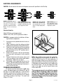
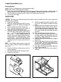
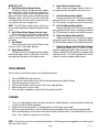
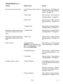
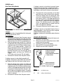
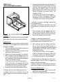
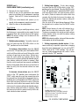
BUNN
®
OT & RT
!
ION NT
UT D DECA
CA DISCAR
IF:
D
Y
KE D
AC HEY EMPTE
. CRRADTCDR EN AM IC
TR
. SCILE WH H FL
HIGELEC
. BOATED
ON D
. HEED POSE
. US EX TS
. OREMEN
EL
RY
JU ON
TS
S IN
EN
ATI
NT
RISK CORPOR
CO
LY -MATIC
EL T
NN E HO COMP
N-O
FU AR
5 BUN
TO
198
RE
ILU
FA
PN:
ER
G
NIN
R
WA
ER
RM
WA
DRY
AT
HE
TER AY
H
AN AW
HIG
DEC ES
IL
IBL
KS
T BO UST
RISUID
NO MB
LY
DO P CO
MP T LIQRD
CO
KEE
ZA
TO RE/HOHA
E
RE ILU
FIR
ILU FA
FA S AND
AS
GL RNS
BU
!
658
ION NT
UT D DECA
CA DISCAR
ER
!
IF:
D
Y
KE D
AC HEY EMPTE
. CRRADTCDR EN AM IC
FL
. SCILE WH H ECTR
HIGEL
. BOATED
ON D
. HEED POSE
. US EX TS
. OREMEN
EL
RY
JU ON
TS
S IN
EN
ATI
NT
RISK CORPOR
CO
LY -MATIC
EL T
NN E HO COMP
N-O
FU AR
5 BUN
TO
198
RE
ILU
FA
PN:
658
OPERATING & SERVICE MANUAL
BUNN-O-MATIC CORPORATION
POST OFFICE BOX 3227
SPRINGFIELD, ILLINOIS 62708-3227
PHONE: (217) 529-6601 FAX: (217) 529-6644
10021.0000G
7/00 © 1989 BUNN-O-MATIC CORPORATION
CONTENTS
Introduction ............................................................... 2
User Notices .............................................................. 3
Electrical Requirements ............................................. 4
Plumbing Requirements ............................................ 4
Initial Set-Up .............................................................. 5
Adjusting Brew Volumes ............................................ 6
Operating Controls..................................................... 6
Coffee Brewing .......................................................... 7
Cleaning ..................................................................... 7
Troubleshooting ......................................................... 8
Service....................................................................... 12
Wiring Diagrams ........................................................ 26
INTRODUCTION
This equipment will brew a half-gallon batch of coffee into an awaiting decanter at the press of a button. The
OT has two and the RT has five warmers to keep the beverage at the right temperature, on the RT one of which is
capable of heating water to boiling. The brewer is only for indoor use on a sturdy counter or shelf.
WARRANTY
Bunn-O-Matic Corp. (“Bunn”) warrants the equipment manufactured by it to be commercially free from defects
in material and workmanship existing at the time of manufacture and appearing within one year from the date of
installation. In addition:
1.) Bunn warrants electronic circuit and/or control boards to be commercially free from defects in material and
workmanship for two years from the date of installation.
2.) Bunn warrants the compressor on refrigeration equipment to be commercially free from defects in material
and workmanship for two years from the date of installation.
3.) Bunn warrants that the grinding burrs on coffee grinding equipment will grind coffee to meet original factory
screen sieve analysis for three years from date of installation or for 30,000 pounds of coffee, whichever comes first.
This warranty does not apply to any equipment, component or part that was not manufactured by Bunn or that,
in Bunn’s judgement, has been affected by misuse, neglect, alteration, improper installation or operation, improper
maintenance or repair, damage or casualty.
THE FOREGOING WARRANTY IS EXCLUSIVE AND IS IN LIEU OF ANY OTHER WARRANTY, WRITTEN OR
ORAL, EXPRESS OR IMPLIED, INCLUDING, BUT NOT LIMITED TO, ANY IMPLIED WARRANTY OF EITHER
MERCHANTABILITY OR FITNESS FOR A PARTICULAR PURPOSE. The agents, dealers or employees of Bunn are
not authorized to make modifications to this warranty or to make additional warranties that are binding on Bunn.
Accordingly, statements by such individuals, whether oral or written, do not constitute warranties and should not
be relied upon.
The Buyer shall give Bunn prompt notice of any claim to be made under this warranty by telephone at (217)
529-6601 or by writing to Post Office Box 3227, Springfield, Illinois, 62708-3227. If requested by Bunn, the Buyer
shall ship the defective equipment prepaid to an authorized Bunn service location. If Bunn determines, in its sole
discretion, that the equipment does not conform to the warranty, Bunn shall repair the equipment with no charge
for parts during the warranty period and no charge for labor by a Bunn Authorized Service Representative during
the warranty period. If Bunn determines that repair is not feasible, Bunn shall, at its sole option, replace the
equipment or refund the purchase price for the equipment.
THE BUYER’S REMEDY AGAINST BUNN FOR THE BREACH OF ANY OBLIGATION ARISING OUT OF THE SALE
OF THIS EQUIPMENT, WHETHER DERIVED FROM WARRANTY OR OTHERWISE, SHALL BE LIMITED, AS
SPECIFIED HEREIN, TO REPAIR OR, AT BUNN’S SOLE OPTION, REPLACEMENT OR REFUND.
In no event shall Bunn be liable for any other damage or loss, including, but not limited to, lost profits, lost sales,
loss of use of equipment, claims of Buyer’s customers, cost of capital, cost of down time, cost of substitute
equipment, facilities or services, or any other special, incidental or consequential damages.
Page 2
10021 071700
USER NOTICES
Carefully read and follow all notices on the equipment and in this manual. They were written for your protection.
All notices on the equipment should be kept in good condition. Replace any unreadable or damaged labels.
00658.0000
00831.0000
! WARNING
HIGH HEAT WARMER
DO NOT BOIL DECANTER DRY
KEEP COMBUSTIBLES AWAY
FAILURE TO COMPLY RISKS
GLASS FAILURE/HOT LIQUID
BURNS AND FIRE HAZARD
00656.0000
00688.0000
Page 3
10021 101598
ELECTRICAL REQUIREMENTS
CAUTION - Do not connect the brewer to the power source until specified in Initial Set-Up.
L2 RED
WHITE
NEUTRAL
L1 BLACK
120V.A.C.
WHITE
L2 RED
120V.A.C.
208 or 240V.A.C.
NEUTRAL
L1 BLACK
RED
200 OR 240V.A.C.
NEUTRAL
L1 BLACK
100V.A.C.
120V.A.C.
L1 BLACK
MODELS OT15 & 20 require 2wire, grounded service rated
120 volts ac, 15 or 20 amp respectively, single phase, 60 Hz.
Model 15 has an attached
cordset.
MODELS OTA, RTA & RT35B
require 2-wire, grounded service rated 240 volts ac or 200
volts ac, 20 amp single phase,
50 Hz.
MODELS OT35 & RT35 require
3-wire, grounded service rated
120/208 or 120/240 volts ac, 20
amp, single phase, 60 Hz.
MODEL RT25B requires 2wire, grounded service
rated 100 volts ac, 20 amp
single phase, 50 Hz.
Electrical Hook-Up
Model OT15 has an attached cordset.
Models OT20, OT35, & RT35, proceed as follows:
CAUTION – Improper electrical installation will damage electronic components.
1.
3.
4.
N
N
U
B
HI
2.
An electrician must provide electrical service as
specified.
Using a voltmeter, check the voltage and color
coding of each conductor at the electrical source.
Remove the front panel beneath the sprayhead
and rotate the control thermostat knob fully
counterclockwise to the "OFF" position and replace the panel.
Remove the rear panel, feed the cord through
the strain relief, and connect it to the terminal
block.
Connect the brewer to the power source and
verify the voltage at the terminal block before
proceeding. Replace the rear panel.
If plumbing is to be hooked-up later be sure the
brewer is disconnected from the power source.
If Plumbing has been hooked-up, the brewer is
ready for Initial Set-Up.
OFF
P1709
PLUMBING REQUIREMENTS
NOTE - Bunn-O-Matic recommends 1/4" copper tubing for installations of less than 25 feet and 3/8" for
more than 25 feet from the 1/2" water supply line. A
tight coil of copper tubing in the water line will facilitate moving the brewer to clean the counter top. BunnO-Matic does not recommend the use of a saddle valve
to install the brewer. The size and shape of the hole
made in the supply line by this type of device may
restrict water flow.
This brewer must be connected to a cold water
system with operating pressure between 20 and 90
psi from a 1/2" or larger supply line. A shut-off valve
should be installed in the line before the brewer. Install a regulator in the line when pressure is greater
than 90 psi to reduce it to 50 psi. The water inlet
fitting is 1/4" flare.
This equipment must be installed to comply
with the Basic Plumbing Code of the Building Officials and Code Administrators International, Inc. (BOCA) and the Food Service
Sanitation Manual of the Food and Drug Administration (FDA).
5.
6.
Page 4
10021 101598
PLUMBING REQUIREMENTS (Cont.)
Plumbing Hook-Up
Model OT15 has an attached water strainer, proceed to step 2.
Models OT20, OT35, & RT35, proceed as follows:
1. Remove the rear panel and bottom pan. Run the long piece of tubing from the strainer (supplied) under the
brewer and attach it to the water inlet fitting on the solenoid. Reinstall the bottom pan and rear panel.
2. Flush the water line and securely attach it to the 1/4" flare fitting on the strainer.
3. Turn on the water supply.
INITIAL SETUP
CAUTION - The brewer must be disconnected from the power source throughout the initial set-up, except when
specified in the instructions.
9. Rotate the control thermostat knob fully clock1. Remove the front panel.
wise to the "ON" position and replace the front
2. Rotate the control thermostat knob fully counpanel.
terclockwise to the "OFF" position and replace the
10. Connect the brewer to the power source and wait
panel.
approximately twenty minutes for the water in
3. Insert an empty funnel into the funnel rails.
the tank to heat to the proper temperature. Some
4. Place a decanter containing a small amount of
water will drip from the funnel during this time;
water on the warmer beneath the funnel.
this is due to expansion and should not occur
5. Connect the brewer to the power source, place
thereafter.
the On/Off brew station warmer switch the up11. Place an empty decanter under the funnel.
per
position, and momentarily press the
12. Place the On/Off brew station warmer switch in
start switch.
Water will begin flowing into
the upper position and momentarily press the
the tank. When water stops flowing into the tank,
start switch. Empty the decanter after water has
initiate a second and a third brew cycle. During
stopped flowing from the funnel.
this third brew cycle the tank will fill to its ca13. Allow the water in the tank to reheat to the proper
pacity and the excess will flow from the
temperature.
sprayhead, out of the funnel, and into the de14. Place an empty decanter on the warmer and press
canter.
the start switch. Check the water volume in the
decanter after water has stopped flowing from
NOTE - The On/Off brew station warmer switch must
the funnel. It should be 64 ounces.
be in the upper position to initiate and complete a
15. If not, adjust the Timer as described in Adjusting
brew cycle.
Brew Volumes (Page 6).
16. Repeat steps 13-15 until 64 oz. water volume is
6. Place the On/Off brew station warmer switch in
achieved.
the lower position.
7. Disconnect the brewer from the power source.
8. Remove the front panel.
J1
J2
IF:
D
CKEHED
TY
. CRAATC
DRY EMP
ME
. SCR
LED WHENFLA IC
. BOITED HIGH CTR
ELE
. HEAD ON D
OSE
. USEEXP
Y
TS UR
. OR MEN INJ
N
ATIO
ELE KS
POR
SET
LOCK
5
TL
4
TL
3
TL
2
TL
ON NTER
UTI DECA
CA DISCARD
SET
!
K
LOC
1
TL
TS
EN
NT
RIS IC COR
CO
LY
EL T
MAT
NN E HO COMP
N-OFU AR
BUN
TO
1985
RE
ILU
FA
PN:
658
P1687
P1690
Page 5
10021 071700
ADJUSTING BREW VOLUMES
CAUTION - Disconnect the power source from the brewer prior to the removal of any panel for the replacement
or adjustment of any component.
NOTE: Prior to setting or modifying batch sizes, check that the brewer is connected to water supply, the tank is
properly filled, and a funnel and server are in place.
1. Modifying batch sizes. To modify a batch volume, first check that the SET/LOCK switch is in the “SET”
position on the circuit board.
To increase a batch size. Press and hold the START or BREW switch until three clicks are heard. Release the
switch (Failure to release the switch within two seconds after the third click causes the volume setting to be
aborted and previous volume setting will remain in memory) and press it again one or more times. Each time
the switch is pressed, two seconds are added to the brew time period. Allow the brew cycle to finish in order
to verify that the desired volume has been achieved.
To decrease a batch size. Press and release the START or BREW switch once for every two-second interval
to be removed from the total brew time period; then immediately press and hold down the START or BREW
switch until three clicks are heard. Release the switch. (Failure to release the switch within two seconds after
the third click causes the volume setting to be aborted and previous volume setting will remain in memory).
Allow the brew cycle to finish in order to verify that the desired volume has been achieved.
2. Setting batch sizes. To set a batch volume, first check that the SET/LOCK switch is in the “SET” position on
the circuit board. Press and hold the START or BREW switch until three distinct clicks are heard, and then
release the switch. (Failure to release the switch within two seconds after the third click causes the volume
setting to be aborted and previous volume setting will remain in memory). View the level of the liquid being
dispensed. When the desired level is reached, turn the ON/OFF switch to “OFF” (lower). The brewer remembers this volume and will continue to brew batches of this size until the volume setting procedure is repeated.
NOTE: When brewing coffee, batch volumes will decrease due to absorption by the coffee grounds.
3. Setting programming disable feature. If it becomes necessary to prevent anyone from changing brew times
once programmed, you can set the SET/LOCK switch to the “LOCK” position. This will prevent any programming to be done until switch is once again placed in the “SET” position.
OPERATING CONTROLS
MODEL OT
MODEL RT
D
E
!
!
ON NTER
UTI DECA
CA DISCARD
IF:
D
CKEHED
TY
. CRAATC
DRY EMP
ME
. SCR
LED WHENFLA IC
. BOITED HIGH CTR
ELE
. HEAD ON D
IF:
D
CKEHED
TY
. CRAATC
DRY EMP
ME
. SCR
LED WHENFLA IC
H
BOITED
HIG CTR
PN:
.
ELE
. HEAD ON D
R
WA
NIN
G
MER
T WAR
DRY
ER
HEA
Y
H
ANT
HIG
DEC ES AWA
KS
BOIL TIBL
RIS
BUS
NOT
ID
PLY
DO
P COM COM T LIQU
KEE
TO
/HO ARD
URE URE HAZ
FAIL FAIL FIRE
SS
GLA NS AND
BUR
!
OSE
. USEEXP
Y
TS
TS . OR MEN INJUR N
EN
ATIO
ELE KS
NT
RIS IC CORPOR
CO
LY
EL T
MAT
NN E HO COMP
N-OFU AR
BUN
TO
1985
RE
ILU
FA
ON NTER
UTI DECA
CA DISCARD
658
OSE
. USEEXP
Y
TS
TS . OR MEN INJUR N
EN
ATIO
ELE KS
NT
RIS IC CORPOR
CO
LY
EL T
MAT
NN E HO COMP
N-OFU AR
BUN
TO
1985
RE
ILU
FA
PN:
658
A
B
C
P1687
F
G
A
B
C
H
I
P1688
Page 6
10021 071700
MODELS OT & RT
A. On/Off Brew Station Warmer Switch
Placing the switch in the upper position supplies
power to the brew station warmer and enables brewing. Placing the switch in the lower position cuts
power to the brew station warmer and stops brewing.
Stopping a brew cycle after it has been started will
not stop the flow of water into the funnel until the
tank syphons down to its proper level.
E.
NOTE - The On/Off brew station warmer switch must
be in the upper position to initiate and complete a brew
cycle.
B. On/Off Brew Station Warmer Indicator Lamp
Glows whenever the On/Off brew station warmer
switch is in the upper position showing that the
warmer is on and that the automatic brew cycle can
be started.
C. Start Switch
Starts a brew cycle when the On/Off brew station
warmer switch is in the upper position.
G. Left Front Warmer Rotary Switch
Rotating the knob to the "ON" position supplies
power to the left front warmer. Rotating the knob to
the "OFF" position cuts power to the left front warmer.
D. Upper Warmer Switch
Placing the switch in the upper position supplies
power to the upper warmer. Placing the switch in the
lower position cuts power to the upper warmer.
Upper Warmer Indicator Lamp
Glows whenever the upper warmer switch is in
the upper position showing that the warmer is on.
F.
Left Rear Warmer Rotary Switch
Rotating the knob to the "ON" position supplies
power to the left rear warmer. Rotating the knob to
the "OFF" position cuts power to the left rear warmer.
H. Right Front Warmer Rotary Switch
Rotating the knob to the "ON" position supplies
power to the right front warmer. Rotating the knob to
the "OFF" position cuts power to the right front warmer.
I.
Right Rear Warmer Three Heat Rotary Switch
Rotating the knob to the "LO", "MED", or "HIGH"
positions supply power to the right rear warmer. Rotating the knob to the "OFF" position cuts power to the
right rear warmer. The “HIGH” position of this switch
makes the warmer capable of boiling water.
COFFEE BREWING
Start each brew cycle with an empty, clean, half-gallon decanter.
1.
2.
3.
4.
5.
6.
Insert a BUNN® filter into the funnel.
Pour the fresh coffee into the filter and level the bed of grounds by gently shaking.
Slide the funnel into the funnel rails.
Place the On/Off brew station warmer switch in the upper position.
Momentarily press the start switch.
When brewing is completed, simply discard the grounds and filter.
CLEANING
1.
2.
3.
The use of a damp cloth rinsed in any mild, non-abrasive, liquid detergent is recommended for cleaning all
surfaces on Bunn-O-Matic equipment.
Check and clean the sprayhead. The sprayhead holes must always remain open.
With the sprayhead removed, insert the deliming spring (provided) all the way into the sprayhead tube.
When inserted properly, no more than two inches of spring should be visible. Saw back and forth five or six
times. Then, repeat this step for the air vent tube.
NOTE - In hard water areas, this may need to be done daily. It will help prevent liming problems in the brewer and
takes less than a minute.
Page 7
10021 071700
TROUBLESHOOTING
A troubleshooting guide is provided to suggest probable causes and remedies for the most likely problems
encountered. If the problem remains after exhausting the troubleshooting steps, contact the Bunn-O-Matic
Technical Service Department.
•
Inspection, testing, and repair of electrical equipment should be performed only by qualified service personnel.
•
All electric components have 120 volt ac voltage on their terminals. Shorting of terminals or the application
of external voltages may result in equipment failure.
•
Intermittent operation of electronic equipment is unlikely. Component failure will normally be permanent. If
an intermittent condition is encountered, the cause will likely be a switch contact or a loose connection at a
terminal or crimp.
•
Solenoid removal requires interrupting the water supply to the valve. Damage may result if solenoids are
energized for more than ten minutes without a supply of water.
•
The use of two wrenches is recommended whenever plumbing fittings are tightened or loosened. This will
help to avoid twists and kinks in the tubing.
•
Make certain that all plumbing connections are sealed and electrical connections tight and isolated.
•
This brewer is heated at all times unless disconnected from the power source. Keep away from combustibles.
WARNING
•
Exercise extreme caution when servicing electrical equipment.
•
Disconnect the brewer from the power source when servicing, except when electrical tests are specified.
•
Follow recommended service procedures
•
Replace all protective shields or safety notices
Problem
Probable Cause
Remedy
Equipment will not operate.
1. No power or incorrect voltage
(A) Connect the brewer to the power
source.
(B) Check the terminal block for the
proper voltages.
(C) Check circuit breaker/fuse.
Brew cycle will not start.
1. No water
Check plumbing and shut-off valves.
2. Water Strainer
(A) Direction of flow arrow must be
pointing towards brewer.
(B) Remove the strainer and check
for obstructions. Clear or replace.
3. Flow Control
(A) Direction of flow arrow must be
pointing away from the solenoid.
(B) Remove the control and check
for obstructions. Clear or replace.
Page 8
10021 101598
TROUBLESHOOTING (cont.)
Remedy
Problem
Probable Cause
Brew cycle will not start. (cont.)
4. On/Off Brew Station Warmer Refer to Service - On/Off Brew Station Warmer Switch for testing proSwitch
cedures. See page 19.
5. Start Switch
Refer to Service - Start Switch for
testing procedures. See page 25.
6. Brew Timer
Refer to Service - Brew Timer for
testing procedures. See page 13 or
14.
7. Solenoid Valve
Refer to Service - Solenoid Valve for
testing procedures. See page 24.
Water flows into tank continuously 1. Solenoid Valve
(On/Off brew station warmer switch
"OFF").
Refer to Service - Solenoid Valve for
testing procedures. See page 24.
Water flows into tank continuously 1. Brew Timer
(On/Off brew station warmer switch
"ON").
Refer to Service - Brew Timer for
testing procedures. See page 13 or
14.
Water is not hot.
Decanter warmer is not hot.
Refer to Service - Limit Thermostat
1. Limit Thermostat
CAUTION: Do not eliminate or by- for testing procedures. See page 23.
pass limit thermostat. Use only
B.O.M. part #29329.1000
2. Control Thermostat
Refer to Service - Control Thermostat for testing procedures. See
page 16.
3. Tank Heater
Refer to Service - Tank Heater for
testing procedures. See page 26.
1. Warmer Switches
(A) The Warmer Switch(es) must be
in the "ON" position for the warmer
to operate.
(B) Refer to Service - Warmer
Switch(es) for testing procedures.
See pages 19,20, & 21.
2. Decanter Warmers
Page 9
Refer to Service - Warmers for testing procedures. See pages 17 & 18.
10021 071700
TROUBLESHOOTING (cont.)
Problem
Probable Cause
Spitting or unusual steaming from 1. Control Thermostat
sprayhead.
2. Lime build-up
CAUTION: Tank and tank components should be delimed regularly
depending on local water conditions.
Excessive mineral build-up on stainless steel surfaces can initiate corrosive reactions resulting in serious
leaks.
Inconsistent beverage level in de- 1. Flow control
canter.
Remedy
Refer to Service - Control Thermostat for testing procedures. See
page 16.
Inspect the tank assembly for excessive lime deposits. Delime as required.
(A) Direction of flow arrow must be
pointing away from the solenoid.
(B) Remove the control and check
for obstructions. Clear or replace.
2. Improper water pressure
Check the operating water pressure
to the brewer. It must be between
20 and 90 psi (138 and 620 kPa).
3. Syphon system
Water should flow freely from the
sprayhead for approximately twenty
seconds after the brew solenoid has
shut-off and then stop flowing
abruptly. The brewer must be level
from front-to-back to syphon properly.
Consistently high or low beverage 1. Brew Timer adjustment
level in decanter.
Adjust the brew timer as required to
achieve the recommended 64 oz for
each brew cycle.
Dripping from sprayhead.
1. Syphon system
Water should flow freely from the
sprayhead for approximately twenty
seconds after the brew solenoid has
shut-off and then stop flowing
abruptly. The brewer must be level
from front-to-back to syphon properly.
2. Solenoid Valve
Refer to Service - Solenoid Valve for
testing procedures. See page 24.
Page 10
10021 071700
TROUBLESHOOTING (cont.)
Problem
Probable Cause
Remedy
Beverage overflows decanter.
1. Beverage left in decanter
The brew cycle should be started
only with an empty decanter under
the funnel.
Weak beverage.
1. Type of paper filters
BUNN® paper filters should be used
for proper extraction.
2. Coffee
A sufficient quantity of fine or drip
grind coffee should be used for
proper extraction.
3. Sprayhead
B.O.M. sprayhead #01082.0000
should be used to properly wet the
bed of ground coffee in the funnel.
4. Funnel loading
The BUNN® paper filter should be
centered in the funnel and the bed
of coffee leveled by gentle shaking.
5. Water temperature
Place a funnel over an empty decanter on the warmer beneath the
sprayhead. Place the On/Off brew
station warmer switch in the upper
position, press the start switch, and
check the water temperature immediately below the sprayhead with an
accurate thermometer. The reading
should not be less than 195° F. Adjust the control thermostat slightly
clockwise to increase the water temperature.
1. Solenoid Valve
The nut on top of the solenoid valve
must be tight or it will vibrate during operation.
2. Plumbing lines
Plumbing lines should not rest on
the counter top.
3. Water supply
(A) The brewer must be connected
to a cold water line.
Brewer is making unusual noises.
Page 11
(B) Water pressure to the brewer
must not be higher than 90 psi (620
kPa). Install a regulator if necessary
to lower the working pressure to approximately 50 psi (345 kPa).
10021 071700
SERVICE
This section provides procedures for testing and replacing various major components used in this brewer
should service become necessary. Refer to Troubleshooting for assistance in determining the cause of any
problem.
Component Access
WARNING - Disconnect the brewer from the power
source before the removal of any panel or the replacement of any component.
The brew timer, and control thermostat are located behind the front panel, FIG. 1 located beneath
the brew funnel, attached with four #8-32 slotted-head
screws.
The base warmer(s), switch(es), indicator lamp,
start switch, tank "keep warm" heater, terminal block,
and solenoid valve, are located in the base. Access is
gained by removing the rear panel, FIG. 1 attached
with two #8-32 slotted-head screws
The limit thermostat, and tank heater are located
on the tank lid. Access is gained by removing the top
lid, FIG. 1 attached with three #8-32 slotted head
screws. On the model OT, the upper warmer, switch,
and associated indicator lamp are located on this removable top lid.
WARNING - Inspection, testing, and repair of electrical equipment should be performed only by qualified
service personnel. The brewer should be disconnected
from the power source when servicing, except when
electrical tests are required and the test procedure
specifically states to connect the brewer to the power
source.
Contents
Brew Timer (Early Models) ................................... 13
Digital Timer (Late Models) .................................. 14
Control Thermostat ............................................... 16
Warmer(s)
OT: Brew Station & Upper ............................................. 17
RT: Left Rear, Left Front, Brew Station, & Right Front ... 17
RT: Right Rear Three Heat ............................................. 18
Warmer Switch(es)
OT: On/Off Brew Station & Upper .................................. 19
RT: On/Off Brew Station ................................................ 19
RT: Left Rear, Left Front, & Right Front Rotary.............. 20
RT: Right Rear Three Heat Rotary ................................. 21
Indicator Lamp(s) ................................................. 22
Limit Thermostat .................................................. 23
Solenoid Valve ...................................................... 24
Start Switch .......................................................... 25
Tank Heater ........................................................... 26
Thermal Cut-off ................................................... 27
Wiring Schematics............................................... 28
!
!
ON NTER
UTI DECA
CA DISCARD
IF:
D
CKEHED
TY
. CRAATC
DRY EMP
ME
. SCR
LED WHENFLA IC
. BOITED HIGH CTR
ELE
. HEAD ON D
OSE
. USEEXP
Y
TS
TS . OR MEN INJUR N
EN
ATIO
ELE KS
NT
RIS IC CORPOR
CO
LY
EL T
MAT
NN E HO COMP
N-OFU AR
BUN
TO
1985
RE
ILU
FA
ON NTER
UTI DECA
CA CARD
R
WA
NIN
G
MER
T WAR
DRY
ER
HEA
Y
H
ANT
HIG
DEC ES AWA
KS
BOIL TIBL
RIS
BUS
NOT
ID
PLY
DO
P COM COM T LIQU
KEE
TO
/HO ARD
URE URE HAZ
FAIL FAIL FIRE
SS
GLA NS AND
BUR
!
DIS
IF:
D
CKEHED
TY
. CRAATC
DRY EMP
ME
. SCR
LED WHENFLA IC
. BOITED HIGH CTR
ELE
. HEAD ON D
PN:
658
OSE
. USEEXP
Y
TS
TS . OR MEN INJUR N
EN
ATIO
ELE KS
NT
RIS IC CORPOR
CO
LY
EL T
MAT
NN E HO COMP
N-OFU AR
BUN
TO
1985
RE
ILU
FA
PN:
P1687
658
FIG. 1 ACCESS PANELS
Page 12
P1688
10021 071700
SERVICE (cont.)
If voltage is present as described, reconnect the polarized, three-pin connectors, and proceed to #6.
If voltage is not present as described, refer to the Wiring Diagrams and check the brewer wiring harness.
Brew Timer (Early Models)
7.
2
1
3
.5
4
5
MINUTES
BUNN-O-MATIC
P/N 2235-120 VAC
6.
8.
P1690
FIG. 2 BREW TIMER
Location:
The brew timer is located behind the front panel
to the right of the tank, FIG. 2.
Test Procedure:
1. Disconnect the brewer from the power source
and separate the polarized, three-pin connectors
between the timer and brewer wiring harness and
rotate the brew timer dial fully counterclockwise.
2. Check the voltage across sockets 2 & 3 (white or
red and black wires) of the female connector with
a voltmeter when the On/Off brew station warmer
switch is in the upper position. Connect the
brewer to the power source. The indication must:
a) 120 volts ac for two wire 120 volt models.
b) 200 or 240 volts ac for two wire 200 volt or
240 volt models and three wire 120/240 volt
models.
c) 100 volts ac for two wire 100 volt models.
3. Disconnect the brewer from the power source.
Disconnect the in-line connectors on the black
and white wires from the timer to the solenoid.
Check the voltage across the black and white
wires with a voltmeter when the On/Off brew station warmer switch is in the upper position and
the start switch is pressed to the lower position
and released. Connect the brewer to the power
source. The indication must be as described in
step 2, for approximately 20 seconds and then
return to its previous indication.
Disconnect the brewer from the power source.
If voltage is present as described, the brew timer is
operating properly. Reset the timer dial as required,
to obtain the desired brew volume.
If voltage is not present as described, replace the brew
timer.
Removal and Replacement:
1. Separate all connectors between the brewer wiring harness and the timer.
2. Remove the two 8-32 slotted-head screws holding the timer to the bracket.
3. Install the new timer to the bracket.
4. Refer to FIG.3 when reconnecting the wires.
5. Readjust the timer dial as required.
3
4
2
5
1
ES
UT ATIC
MIN -M VAC
-O 0
NN -12
BU 235
2
P/N
.5
P1 BLU to Start Switch
P2 WHI (see below)
P3 BLK to ON/OFF Brew Station
Warmer Switch
If voltage is present as described, proceed to #4.
If voltage is not present as described, refer to the Wiring Diagrams and check the brewer wiring harness.
4.
5.
Check the voltage across sockets 1 & 2 (blue and
white or red wires) of the female connector with
a voltmeter when the On/Off brew station warmer
switch is in the upper position and the start switch
is pressed to the lower position and held. Connect the brewer to the power source. The indication must be as described in step 2, until the start
switch is released.
Disconnect the brewer from the power source.
WHI to Solenoid Coil
BLK to Solenoid Coil
FIG. 3 BREW TIMER WIRING
MODEL
OT
WHI
to Indicator Lamp
RT
to Brew Station Warmer
Page 13
WHI
P1691
10021 071700
SERVICE (cont.)
DIGITAL BREW TIMER (Late Models)
J1
6. Disconnect the white/blue wire from terminal TL3
and the blue/black wire from terminal TL5. With a
voltmeter, check for continuity across the two
wires when the "ON/OFF" switch is in the "ON"
position (upper) and the START switch is pressed.
Connect the brewer to the power source. The
indication must be:
a) 120 volts ac for two wire 120 volt models.
b) 200 or 240 volts ac for two wire 200 or 240
volt models and three wire 120/240 volt models.
c) 100 volts ac for two wire 100 volt models.
J2
SET
SET
LOCK
5
TL
4
TL
3
TL
2
TL
K
LOC
1
TL
If continuity is present as described, reconnect the
wires and proceed to #7.
If continuity is not present as described, refer to the
Wiring Diagrams and check the brewer wiring harness.
P2201
FIG. 4 DIGITAL BREW TIMER
Location:
The timers are located inside the front of the trunk
on the upper right side of the component brackets.
Test Procedure.
NOTE: Do not remove or install wires while timer board
is installed. Pressure applied to one side may cause
damage to the board.
1. Disconnect the brewer from the power source and
remove the front access panel.
2. Remove the one #8-32 screw securing circuit
board to the mounting bracket.
3. Remove circuit board and spacers (as required).
4. With a voltmeter, check the voltage across terminals TL1 and TL2 when the "ON/OFF" switch is in
the "ON" position. Connect the brewer to the power
source. The indication must be:
a) 120 volts ac for two wire 120 volt models.
b) 200 or 240 volts ac for two wire 200 or 240
volt models and three wire 120/240 volt models.
c) 100 volts ac for two wire 100 volt models.
5. Disconnect the brewer from the power source.
If voltage is present as described, proceed to #6.
If voltage is not present as described, refer to the
Wiring Diagrams and check the brewer wiring harness.
7. With a voltmeter, check the voltage across terminals TL1 and TL4 when the "ON/OFF" switch is in
the "ON" position. Connect the brewer to the power
source. The indication must be 0 volts.
If voltage is as described, proceed to #8.
If voltage is not as described, disconnect the brewer
from the power source and replace the timer.
8. With a voltmeter, check the voltage across terminals TL1 and TL4 when the "ON/OFF" switch is in
the "ON" position. Connect the brewer to the power
source and press the "START" switch. The indication must be as follows:
a) 120 volts ac for two wire 120 volt models.
b) 200 or 240 volts ac for two wire 200 or 240
volt models and three wire 120/240 volt models.
c) 100 volts ac for two wire 100 volt models.
If voltage is present as described, the brew timer is
operating properly. Reset the timer as required, to
obtain the desired brew volume.
If voltage is not present as described, disconnect the
brewer from the power source and replace the timer.
Removal and Replacement:
1. Remove the one #8-32 screw securing circuit
board to the mounting bracket.
2. Remove circuit board and spacers (as required).
Page 14
10021 071700
SERVICE (cont.)
DIGITAL BREW TIMER (Late Models)(cont.)
3. Remove all wires from the timer.
4. Attach all wires to the replacement timer board
prior to installation to the component mounting
bracket. Refer to FIG. 5 when reconnecting the
wires.
5. Install new circuit board with spacers (as required) to the component mounting bracket.
6. Adjust the timer as described below.
Timer Setting:
NOTE: Prior to setting or modifying volumes, check
that the brewer is connected to water supply, the tank
is properly filled, and a funnel and server are in place.
NOTE: All volume settings must be done with the
sprayhead installed.
1. Modifying brew volumes. To modify a brew volume, first check that the SET/LOCK switch is in the
“SET” position on the circuit board.
To increase a brew volume, place the ON/OFF
switch in the “ON” position, press and hold the START
switch until three clicks are heard. Release the switch
and press it again one or more times. (Failure to release the switch within two seconds after the third
click causes the volume setting to be aborted and previous volume setting will remain in memory.) Each
time the switch is pressed, two seconds are added to
the brew time period. Allow the brew cycle to finish in
order to verify that the desired volume has been
achieved.
2. Setting brew volumes. To set a brew volume,
first check that the SET/LOCK switch is in the “SET”
position on the circuit board. Place the ON/OFF switch
in the “ON” position, press and hold the START switch
until three distinct clicks are heard and then release
the switch. (Failure to release the switch within two
seconds after the third click causes the volume setting to be aborted and previous volume setting will
remain in memory.)
View the level of the liquid being dispensed. When
the desired level is reached, turn the ON/OFF switch
to “OFF”.
NOTE: Several ounces of water will continue to syphon from the tank after turning the switch “OFF”.
The brewer remembers this volume and will continue
to brew batches of this size until the volume setting
procedure is repeated.
NOTE: When brewing coffee, volume will decrease due
to absorption by the coffee grounds.
3. Setting programming disable feature. If it becomes necessary to prevent anyone from changing
brew time once programmed, you can set the SET/
LOCK switch to the “LOCK” position. This will prevent any further programming until switch is once
again put into the “SET” position.
To decrease a brew volume, place the ON/OFF
switch in the “ON” position, press and release the
START switch once for every two-second interval to
be removed from the total brew time period; then immediately press and hold down the START switch until
three clicks are heard. Release the switch. (Failure to
release the switch within two seconds after the third
click causes the volume setting to be aborted and previous volume setting will remain in memory). Allow
the brew cycle to finish in order to verify that the desired volume has been achieved.
BLU/BLK wire from TL5 to P1
WHI/GRN wire from TL4 to (WHI) Solenoid
WHI/BLU wire from TL3 to (BLK) Solenoid
WHI wire from TL2 to P2
BLK wire from TL1 to P3
P2037
FIG. 5 DIGITAL TIMER WIRING
Page 15
10021 071700
SERVICE (cont.)
Control Thermostat
5.
The indication must be as described in step 2.
Voltage must not be indicated across these terminals when the thermostat is turned "OFF" (fully
counterclockwise).
Disconnect the brewer from the power source.
If voltage is present as described, the control thermostat is operating properly.
If voltage is not present as described, replace the control thermostat.
U
N
N
HI
B
Removal and Replacement:
1. Remove both wires from the control thermostat
terminals.
2. Remove the top lid from the brewer to gain access to the thermostat bulb.
3. Remove the thermostat bulb by firmly pullingup on the capillary tube at the tank lid. This will
disengage the grommet from the tank lid.
4. Remove the two #8-32 screws holding the control thermostat to the bracket.
5. Fasten the new control thermostat to the brewer
housing.
6. Route the capillary tube up though the brewer
trunk.
OFF
P1689
FIG. 6 CONTROL THERMOSTAT
Location:
The control thermostat is located behind the front
panel, FIG. 6 to the left of the tank.
To test the control thermostat, access will also
be needed to the tank heater located in the top of the
brewer.
Test Procedure:
1. Disconnect the brewer from the power source.
2. Check the voltage across the blue wire on the
control thermostat and the white or red wire on
the tank heater with a voltmeter. Connect the
brewer to the power source. The indication must
be:
a) 120 volts ac for two wire 120 volt models.
b) 200 or 240 volts ac for two wire 200 volt or
240 volt models and three wire 120/240 volt
models.
c) 100 volts ac for two wire 100 volt models.
3. Disconnect the brewer from the power source.
NOTE - Make sure that the capillary tube is away from
any electrical termination and is not kinked.
7.
Slide the grommet to the red mark on the capillary tube.
8. Insert the bulb through the hole in the tank lid
and press the grommet firmly and evenly so that
the groove in the grommet fits into the tank lid.
9. Carefully bend the capillary tube so that the tube
and bulb inside the tank are in a vertical position.
10. Refer to FIG. 7 when reconnecting the wires.
11. Readjust the control thermostat dial as required.
BLU to Limit Thermostat
BLK to Tank Heater
If voltage is present as described, proceed to #4.
If voltage is not present as described, refer to the Wiring Diagrams and check the brewer wiring harness.
4.
Check the voltage across the black wire terminal
of the control thermostat and the white or red
wire on the tank heater with a voltmeter when
the control thermostat is turned "ON" (fully clockwise). Connect the brewer to the power source.
Page 16
P1098
FIG. 7 THERMOSTAT WIRING
10021 071700
SERVICE (cont.)
5.
Warmer(s)
OT: Brew Station & Upper
RT: Left Rear, Left Front, Brew Station, & Right Front
If continuity is present as described, proceed to #6.
If continuity is not present as described, refer to the
Wiring Diagrams and check the brewer wiring harness.
6.
!
ION ANT
UT D DEC
CA DISCAR
Check for continuity across the two terminals on
the warmer.
If continuity is present as described, the warmer is
operating properly.
If continuity is not present as described, replace the
warmer.
ER
IF:
D
CKE
. CRAATCHED
TY
. SCRED DRY N EMP
ME
WHE FLA IC
. BOIL
TED HIGH CTR
. HEA ON ELE
D
D
URY
TS . USEEXPOSEINJ
ION
TEN
TS
ORAT
. ORRISKS
MEN
CORP
CON
TIC
ELE
PLY
NEL HOT
-O-MA
COM BUNN
FUNARE
1985
E TO
LUR
FAI
PN:
Check for continuity from the wire terminal of
the white or red wire to the splice or indicator
lamp using the chart below.
658
FIG. 8 WARMERS
!
ION ANT
UT D DEC
CA DISCAR
IF:
D
CKE
. CRAATCHED
TY
. SCRED DRY N EMP
ME
WHE FLA IC
. BOIL
TED HIGH CTR
. HEA ON ELE
D
D
URY
TS . USEEXPOSE
INJ
ION
TEN
TS
ORAT
. ORRISKS
MEN
CORP
CON
TIC
ELE
PLY
NEL HOT
-O-MA
COM BUNN
FUNARE
1985
E TO
LUR
FAI
PN:
Removal and Replacement:
1. Remove the #4-40 slotted-head screws holding
the warmer to the brewer
2. Lift the warmer assembly from the brewer.
3. Disconnect both wires from the warmer.
4. Refer to FIG. 10 when reconnecting the wires.
5. Place the new warmer into the brewer and securely attach it using the #4-40 screws.
P1687
ER
WHI or RED (see below)
NING
WAR
MER
T WAR
DRY
HEA
NTER
HIGH
AWAY
DECA
S
BOIL
IBLES
RISK
NOT
BUST PLY
ID
DO
COM
LIQU
COM
KEEP TO
/HOT ARD
URE URE
HAZ
FAIL FAIL
FIRE
SS
AND
NS
BUR
!
GLA
658
BLK to Warmer Switch
FIG. 9 WARMERS
P1692
P1688
FIG. 10 WARMER WIRING
Location:
OT: One of the warmers is beneath the brew funnel
and the other is on the top lid, FIG. 8.
RT: These warmers include the one beneath the
brew funnel, the ones on the right and left of the brew
station, and the one above and to the left of the brew
station as viewed from the front, FIG. 9.
Test Procedure:
1. Once the switch has been tested and switch failure has been eliminated, proceed as follows.
2. Disconnect the brewer from the power source
and remove the #4-40 screws attaching the
warmer being tested.
3. Lift the warmer assembly from the brewer and
invert the warmer making the wire terminals accessible for testing.
4. Check for continuity from the switch to the black
wire at the warmer element.
MODEL
OT Upper
WHI OR RED
to Indicator Lamp
OT Brew Station
WHI OR RED
to Indicator Lamp
to Terminal Block
RT Left Rear
WHI OR RED
to Terminal Block
to Brew Station Warmer
RT Left Front
WHI OR RED
to Indicator Lamp
RT Brew Station
WHI OR RED
to Timer P2
to Left Rear Warmer
RT Right Front
WHI OR RED
to Right Rear Warmer Switch
If continuity is present as described, proceed to #5.
Page 17
10021 071700
SERVICE (cont.)
If continuity is present as described, proceed to #5.
If continuity is not present as described, refer to the
Wiring Diagrams and check the brewer wiring harness.
Warmer
RT: Right Rear Three Heat
5.
!
ION ANT
UT D DEC
CA DISCAR
IF:
D
CKE
. CRAATCHED
TY
. SCRED DRY N EMP
ME
WHE FLA IC
. BOIL
TED HIGH CTR
. HEA ON ELE
D
D
URY
TS . USEEXPOSE
INJ
ION
TEN
TS
ORAT
. ORRISKS
MEN
CORP
CON
TIC
ELE
PLY
NEL HOT
-O-MA
COM BUNN
FUNARE
1985
E TO
LUR
FAI
PN:
If continuity is present as described, the warmer is
operating properly.
If continuity is not present as described, replace the
warmer.
ER
NING
WAR
MER
T WAR
DRY
HEA
NTER
HIGH
AWAY
DECA
S
BOIL
IBLES
RISK
NOT
BUST PLY
ID
DO
COM
LIQU
COM
KEEP TO
/HOT ARD
URE URE
HAZ
FAIL FAIL
FIRE
SS
AND
NS
BUR
!
Check for continuity across the two outside terminals on the warmer. Then across one of the
outside terminals and the center terminal. Finally, across the other outside terminal, and the
center terminal.
GLA
658
Removal and Replacement:
1. Remove the #4-40 slotted-head screws holding
the warmer to the brewer
2. Lift the warmer assembly from the brewer.
3. Disconnect the wires from the warmer.
4. Refer to FIG. 12 when reconnecting the wires.
5. Place the new warmer into the brewer and securely attach it using the #4-40 screws.
P1688
FIG. 11 THREE HEAT WARMER
Location:
The three heat warmer is above and to the right of the
brew station as viewed from the front, FIG. 11.
Test Procedure:
1. Once the switch has been tested and switch failure has been eliminated, proceed as follows.
2. Disconnect the brewer from the power source
and remove the #4-40 screws attaching the
warmer being tested.
3. Lift the warmer assembly from the brewer and
invert the warmer making the wire terminals accessible for testing.
4. Check for continuity of the red wire, the white
wire, then the brown wire from the switch to the
warmer element.
Page 18
RED to Right Rear Warmer
Switch 3
WHI to Right Rear Warmer
Switch 1
BRN to Right Rear Warmer
Switch 2
P1693
FIG. 12 THREE HEAT WARMER WIRING
10021 071700
If voltage is present as described, proceed to #4.
If voltage is not present as described, refer to the Wiring Diagrams and check the brewer wiring harness.
SERVICE (cont.)
Warmer Switch(es)
OT: On/Off Brew Station & Upper
RT: On/Off Brew Station
!
ION ANT
UT D DEC
CA DISCAR
4.
5.
ER
IF:
D
CKE
. CRAATCHED
TY
. SCRED DRY N EMP
ME
WHE FLA IC
. BOIL
TED HIGH CTR
. HEA ON ELE
Check the voltage across the other switch terminal and the terminal on the indicator lamp with
white or red wires with a voltmeter when the
switch is in the upper position. Connect the
brewer to the power source. The indication must
be as described in step 2. Voltage must not be
present across these terminals in the lower position.
Disconnect the brewer from the power source.
D
D
URY
TS . USEEXPOSE
INJ
ION
TEN
TS
ORAT
. ORRISKS
MEN
CORP
CON
TIC
ELE
PLY
NEL HOT
-O-MA
COM BUNN
FUNARE
1985
E TO
LUR
FAI
PN:
658
If voltage is present as described the switch is operating properly.
If voltage is not present as described, replace the
switch.
Removal and Replacement:
1. Compress the clips inside the housing and gently push the switch through the opening.
2. Remove the wires from the switch terminals.
3. Refer to FIG. 15 when reconnecting the wires.
4. Push the new switch firmly into the opening.
P1687
FIG. 13 WARMER SWITCHES
BLK (A) (see below)
ION ANT
UT D DEC
CA DISCAR
ER
!
IF:
D
CKE
. CRAATCHED
TY
. SCRED DRY N EMP
ME
WHE FLA IC
. BOIL
TED HIGH CTR
. HEAD ON D ELE
URY
TS . USEEXPOSE
INJ
ION
TEN
TS
ORAT
. ORRISKS
MEN
CORP
CON
TIC
ELE
PLY
NEL HOT
-O-MA
COM BUNN
FUNARE
1985
E TO
LUR
FAI
PN:
!
WAR
NI
NG
MER
T WAR
DRY
HEA
NTER
HIGH
DECA
AWAY
S
RISK
NOT
BUST PLY
ID
DO
COM
LIQU
COM
KEEP TO
/HOT ARD
URE URE
HAZ
FAIL FAIL
FIRE
SS
AND
GLA
NS
BUR
BOIL
IBLES
658
BLK (B) (see below)
P1697
FIG. 15 WARMER SWITCH WIRING
P1688
FIG. 14 WARMER SWITCHES
Location:
These switches are located beneath and to the
left of their associated warmers as viewed from the
front, FIG.s 13 and 14.
Test Procedure:
1. Locate the switch terminal with black wires that
do not go to the nearby indicator lamp.
2. Check the voltage across this terminal and the
terminal on the indicator lamp with white or red
wires with a voltmeter. Connect the brewer to
the power source. The indication must be:
a) 120 volts ac for two wire 120 volt models.
b) 200 or 240 volts ac for two wire 200 volt or
240 volt models and three wire 120/240 volt
models.
c) 100 volts ac for two wire 100 volt models.
3. Disconnect the brewer from the power source.
MODEL
OT Upper
BLK A
BLK B
OT On/Off Brew Station
BLK A
BLK B
RT On/Off Brew Station
BLK A
Page 19
BLK B
to Warmer
to Indicator Lamp
to Harness P3
to Indicator Lamp
to Brew Station Warmer
to Timer P3
to Terminal Block
to Indicator Lamp
to Timer P3
to Brew Station Warmer
to Left Front Warmer Switch
to Right Front Warmer Switch
10021 071700
SERVICE (cont.)
3.
Warmer Switch(es)
RT: Left Rear, Left Front, & Right Front
4.
ION ANT
UT D DEC
CA DISCAR
If voltage is present as described, the switch is operating properly.
If voltage is not present as described, replace the
switch.
ER
!
IF:
D
CKE
. CRAATCHED
TY
. SCRED DRY N EMP
ME
WHE FLA IC
. BOIL
TED HIGH CTR
. HEA ON ELE
D
D
URY
TS . USEEXPOSE
INJ
ION
TEN
TS
ORAT
. ORRISKS
MEN
CORP
CON
TIC
ELE
PLY
NEL HOT
-O-MA
COM BUNN
FUNARE
1985
E TO
LUR
FAI
PN:
WAR
NI
NG
MER
T WAR
DRY
HEA
NTER
HIGH
AWAY
DECA
S
BOIL
IBLES
RISK
NOT
BUST PLY
ID
DO
COM
LIQU
COM
KEEP TO
/HOT ARD
URE URE
HAZ
FAIL FAIL
FIRE
SS
AND
GLA
NS
BUR
!
Check the voltage across terminal 1 and the white
or red wire on the terminal block with a voltmeter when the switch is in the "ON" position. Connect the brewer to the power source. The indication must be as described in step 1. Voltage must
not be present across these terminals in the "OFF"
positions.
Disconnect the brewer from the power source.
658
Removal and Replacement:
1. Remove the knob from the switch.
2. Loosen the 5/8" nut on the switch shaft and push
the switch through the opening.
3. Remove the wires from the switch terminals.
4. Refer to FIG. 17 when reconnecting the wires.
5. Securely mount the new switch onto the housing and reinstall the knob.
P1688
FIG. 16 WARMER SWITCHES
Location:
These warmer switches are the two at the left
and the left most one on the right of the base as viewed
from the front, FIG. 16. Their knobs are marked Off/
On/Off/On.
To test these switches, access will also be needed
to the terminal block located in the rear of the brewer.
Test Procedure:
1. Check the voltage across terminal L1 and the
white or red wire on the terminal block with a
voltmeter. Connect the brewer to the power
source. The indication must be:
a) 120 volts ac for two wire 120 volt models.
b) 200 or 240 volts ac for two wire 200 volt or
240 volt models and three wire 120/240 volt
models.
c) 100 volts ac for two wire 100 volt models.
2. Disconnect the brewer from the power source.
If voltage is present as described, proceed to #3.
If voltage is not present as described, refer to the Wiring Diagrams and check the brewer wiring harness.
L1
BLK (L1) (see below)
BLK (1) (see below)
1
P1695
FIG. 17 WARMER SWITCH WIRING
MODEL
RT Left Rear
BLK L1 to Warmer
BLK 1 to Left Front Warmer Switch
RT Left Front
BLK L1 to Warmer
BLK 1 to Left Rear Warmer Switch
to Brew Station Warmer Switch
RT Right Front
BLK L1 to Warmer
BLK 1 to Terminal Block
to Brew Station Warmer Switch
Page 20
10021 071700
SERVICE (cont.)
5.
Check the voltage across terminals L1 and 2 with
a voltmeter when the switch is in the "High" position. Connect the brewer to the power source.
The indication must be as described in step 1.
Voltage must not be present across these terminals in the "Off", "Low", or "Med" positions.
6. Disconnect the brewer from the power source.
7. Check the voltage across terminals N and 1 with
a voltmeter when the switch is in the "Med" or
"High" positions. Connect the brewer to the power
source. The indication must be as described in
step 1. Voltage must not be present across these
terminals in the "Off" or "Low" positions.
8. Disconnect the brewer from the power source.
9. Check the voltage across terminals N and 2 with
a voltmeter when the switch is in the "Low" position. Connect the brewer to the power source.
The indication must be as described in step 1.
Voltage must not be present across these terminals in the "Off", "Med", or "High" positions.
10. Disconnect the brewer from the power source.
Warmer Switch(es)
RT: Right Rear Three Heat Rotary
!
ON NTER
UTI DECA
CA DISCARD
IF:
D
CKEHED
TY
. CRAATC
DRY EMP
ME
. SCR
LED WHENFLA IC
. BOITED HIGH CTR
ELE
. HEAD ON D
OSE
. USEEXP
Y
TS
TS . OR MEN INJUR N
EN
ATIO
ELE KS
NT
RIS IC CORPOR
CO
LY
EL T
MAT
NN E HO COMP
N-OFU AR
BUN
TO
1985
RE
ILU
FA
PN:
R
WA
NIN
G
MER
T WAR
DRY
ER
HEA
Y
H
ANT
HIG
DEC ES AWA
KS
BOIL TIBL
RIS
BUS
NOT
ID
PLY
DO
P COM COM T LIQU
KEE
TO
/HO ARD
URE URE HAZ
FAIL FAIL FIRE
SS
GLA NS AND
BUR
!
658
If voltage is present as described, the switch is operating properly.
If voltage is not present as described, replace the
switch.
P1688
FIG. 18 THREE HEAT WARMER SWITCH
Location:
This switch is the farthest on the right of the base as
viewed from the front, FIG. 18. Its knob is marked
Off/Low/Med/High.
Test Procedure:
1. Check the voltage across terminals L1 and N with
a voltmeter. Connect the brewer to the power
source. The indication must be:
a) 120 volts ac for two wire 120 volt models.
b) 200 or 240 volts ac for two wire 200 volt or
240 volt models and three wire 120/240 volt
models.
c) 100 volts ac for two wire 100 volt models.
2. Disconnect the brewer from the power source.
Removal and Replacement:
1. Remove the knob from the switch.
2. Loosen the 5/8" nut on the switch shaft and push
the switch through the opening.
3. Remove the wires from the switch terminals.
4. Refer to FIG. 19 when reconnecting the wires.
5. Securely mount the new switch onto the housing and reinstall the knob.
NOTE: Switch must be installed right side up.
WHI or RED to Terminal Block
WHI or RED to Right Front
Warmer
WHI or RED to Indicator Lamp
N
L1
If voltage is present as described, proceed to #3.
If voltage is not present as described, refer to the Wiring Diagrams and check the brewer wiring harness.
3.
4.
Check the voltage across terminals L1 and 3 with
a voltmeter when the switch is in the "Low", "Med",
or "High" positions. Connect the brewer to the
power source. The indication must be as described in step 1. Voltage must not be present
across these terminals in the "Off" position.
Disconnect the brewer from the power source.
1 2
RED or BLACK to Terminal
Block
3
RED to Right Rear Warmer
BRN to Right Rear Warmer
WHI to Right Rear Warmer
P1696
FIG. 19 THREE HEAT WARMER SWITCH WIRING
Page 21
10021 071700
c) 100 volts ac for two wire 100 volt models.
SERVICE (cont.)
4.
Indicator Lamp(s)
Disconnect the brewer from the power source.
If voltage is present, the indicator lamp is operating
properly.
If voltage is not present, replace the indicator lamp.
!
ION ANT
UT D DEC
CA DISCAR
Removal and Replacement:
1. Compress the clips inside the housing and gently push the indicator lamp through the opening.
2. Remove the wires from the indicator lamp terminals.
3. Refer to FIG. 22 when reconnecting the wires.
4. Push the new indicator lamp firmly into the
opening.
ER
IF:
D
CKE
. CRAATCHED
TY
. SCRED DRY N EMP
ME
WHE FLA IC
. BOIL
TED HIGH CTR
. HEA ON ELE
D
D
URY
TS . USEEXPOSE
INJ
ION
TEN
TS
ORAT
. ORRISKS
MEN
CORP
CON
TIC
ELE
PLY
NEL HOT
-O-MA
COM BUNN
FUNARE
1985
E TO
LUR
FAI
PN:
658
P1687
FIG. 20 INDICATOR LAMP - MODEL OT
WHI or RED
(see below)
BLK (see below)
!
ION ANT
UT D DEC
CA DISCAR
IF:
D
CKE
. CRAATCHED
TY
. SCRED DRY N EMP
ME
WHE FLA IC
. BOIL
TED HIGH CTR
. HEAD ON D ELE
URY
TS . USEEXPOSE
INJ
ION
TEN
TS
ORAT
. ORRISKS
MEN
CORP
CON
TIC
ELE
PLY
NEL HOT
-O-MA
COM BUNN
FUNARE
1985
E TO
LUR
FAI
PN:
ER
NING
WAR
MER
T WAR
DRY
HEA
NTER
!
HIGH
DECA
BOIL
DO
NOT
AWAY
S
IBLES
RISK
BUST PLY
ID
COM
LIQU
COM
KEEP TO
/HOT ARD
URE URE
HAZ
FAIL FAIL
FIRE
SS
AND
NS
BUR
GLA
658
P1694
FIG. 22 INDICATOR LAMP WIRING
P1688
FIG. 21 INDICATOR LAMP - MODEL RT
Location:
The indicator lamps are located beneath their associated warmers, FIG.s 20 and 21.
MODEL
OT Upper
Test Procedure:
1. Check continuity of the black wire from the switch
to the indicator lamp.
2. Check continuity of the white or red wire from
the indicator lamp to the terminal block.
OT Lower
If continuity is present, proceed to #3.
If continuity is not present, refer to Wiring Diagrams
and check brewer wiring harness.
RT
BLK
WHI or RED
to Warmer Switch
to Warmer
to Harness P2
BLK
to Start Switch
to On/Off Brew Station Warmer
Switch
to Timer P2
to Brew Station Warmer
WHI or RED
BLK
WHI or RED
3.
Check for voltage across the indicator lamp terminals. Connect the brewer to the power source.
The indication must be:
a) 120 volts ac for two wire 120 volt models.
b) 200 or 240 volts ac for two wire 200 volt or
240 volt models and three wire 120/240 volt
models.
Page 22
to Start Switch
to On/Off Brew Station Warmer
Switch
to Right Rear Warmer Switch
to Left Front Warmer
10021 071700
SERVICE (cont.)
4.
Limit Thermostat
Check for continuity across the limit thermostat
terminals.
If continuity is present as described, the limit thermostat is operating properly.
If continuity is not present as described, replace the
limit thermostat.
Removal and Replacement:
1. Remove both wires from the limit thermostat terminals.
2. Carefully slide the limit thermostat out from under the retaining clip.
3. Carefully slide the new limit thermostat into the
retaining clip.
4. Refer to FIG. 24 when reconnecting the wires.
P1698
FIG. 23 LIMIT THERMOSTAT
Location:
The limit thermostat is located on the tank lid between
the tank heater terminals, FIG. 23.
Test Procedure:
1. Disconnect the brewer from the power source.
2. Check voltage across the black wire from the limit
thermostat and the white or red wire on the tank
heater terminal. Connect the brewer to the power
source. The indication must be:
a) 120 volts ac for two wire 120 volt models.
b) 200 or 240 volts ac for two wire 200 volt or
240 volt models and three wire 120/240 volt
models.
c) 100 volts ac for two wire 100 volt models.
3. Disconnect the brewer from the power source.
BLK to Terminal Block
BLU to BLU Lead from
Control Thermostat
P1984
FIG. 24 LIMIT THERMOSTAT WIRING
If voltage is present as described, proceed to #4.
If voltage is not present as described, refer to the Wiring Diagrams and check the brewer wiring harness.
Page 23
10021 071700
4.
SERVICE (cont.)
Solenoid Valve
5.
Check the solenoid valve for coil action. Connect the brewer to the power source, place the
On/Off brew station warmer switch in the upper
position, press and release the start switch. Listen carefully in the vicinity of the solenoid valve
for a "clicking" sound as the coil magnet attracts
and after the approximate setting on the brew
timer dial, repels the plunger.
Disconnect the brewer from the power source.
If the sound is heard as described and water will not
pass through the solenoid valve, there may be a blockage in the water line before or after the solenoid valve
or, the solenoid valve may require inspection for wear,
and removal of waterborne particles.
If the sound is not heard as described, replace the
solenoid valve.
P1699
FIG. 25 SOLENOID VALVE
Location:
The solenoid valve is located below and to the left of
the tank as viewed from the rear, FIG. 25.
Test Procedure:
1. Check the voltage across the white and black
wires with a voltmeter when the On/Off brew station warmer switch is in the upper position and
the start switch is pressed to the lower position
and released. Connect the brewer to the power
source. The indication must be:
a) 120 volts ac for two wire 120 volt models and
three wire 120/240 volt models,
b) 200 or 240 volts ac for two wire 200 volt or
240 volt models,
c) 100 volts ac for two wire 100 volt models,
for the approximate setting on the brew timer dial
and then return to zero.
2. Disconnect the brewer from the power source.
Removal and Replacement:
1. Remove all wires from the solenoid valve coil.
2. Turn off the water supply to the brewer.
3. Remove the bottom pan attached with one or
more 8-32 slotted-head screw(s) beneath the
front of the brewer.
4. Raise the brewer approximately six inches from
the counter top and support the feet on something sturdy.
5. Disconnect the water lines to and from the solenoid valve.
6. Remove the two 10-32 screws holding the solenoid valve to the bracket.
7. Lift-out the solenoid valve.
8. Securely install the new solenoid valve to the
bracket. Check the direction of flow arrow on
the valve. It must be pointing toward the flow
control.
9. Securely fasten the water lines to and from the
solenoid valve.
10. Refer to FIG. 26 when reconnecting the wires.
If voltage is present as described, proceed to #3.
If voltage is not present as described, refer to the Wiring Diagrams and check the brewer wiring harness.
3.
Check for continuity across the solenoid valve
coil terminals.
BLK to Brew Timer
WHI to Brew Timer
If continuity is present as described, reconnect the
white and black wires and proceed to #4.
If continuity is not present as described, replace the
solenoid valve.
P1588
FIG. 26 SOLENOID VALVE WIRING
Page 24
10021 071700
SERVICE (cont.)
If continuity is present as described, reconnect the
wires, the switch is operating properly.
If continuity is not present as described, replace the
switch.
Start Switch
!
ION ANT
UT D DEC
CA DISCAR
Removal and Replacement:
1. Remove all wires from the switch terminals.
2. Compress the clips inside the housing and gently push the switch through the opening.
3. Push the new switch into the opening and spread
the clips to hold the switch captive in the housing.
4. Refer to FIG. 29 when reconnecting the wires.
ER
IF:
D
CKE
. CRAATCHED
TY
. SCRED DRY N EMP
ME
WHE FLA IC
. BOIL
TED HIGH CTR
. HEA ON ELE
D
D
URY
TS . USEEXPOSE
INJ
ION
TEN
TS
ORAT
. ORRISKS
MEN
CORP
CON
TIC
ELE
PLY
NEL HOT
-O-MA
COM BUNN
FUNARE
1985
E TO
LUR
FAI
PN:
658
P1687
FIG. 27 START SWITCH - MODEL OT
ION ANT
UT D DEC
CA DISCAR
ER
!
IF:
D
CKE
. CRAATCHED
TY
. SCRED DRY N EMP
ME
WHE FLA IC
. BOIL
TED HIGH CTR
. HEA ON ELE
D
D
URY
TS . USEEXPOSE
INJ
ION
TEN
TS
ORAT
. ORRISKS
MEN
CORP
CON
TIC
ELE
PLY
NEL HOT
-O-MA
COM BUNN
FUNARE
1985
E TO
LUR
FAI
PN:
WAR
NI
NG
MER
T WAR
DRY
HEA
NTER
HIGH
AWAY
DECA
S
BOIL
IBLES
RISK
NOT
BUST PLY
ID
DO
COM
LIQU
COM
KEEP TO
/HOT ARD
URE URE
HAZ
FAIL FAIL
FIRE
SS
AND
GLA
NS
BUR
!
658
BLU to Timer P1
BLK to Indicator
Lamp
P1697
P1688
FIG. 29 START SWITCH WIRING
FIG. 28 START SWITCH - MODEL RT
Location:
The start switch is located in the base, below and to
the right of the brew station, FIG.s 27 & 28.
Test Procedure:
1. Disconnect the brewer from the power source
and remove the wires from both terminals of the
start switch.
2. Check for continuity across the two terminals on
the switch when it is held in the lower position.
Continuity must not be present across these terminals in the upper position.
Page 25
10021 071700
SERVICE (cont.)
Tank Heater
FIG. 30 TANK HEATER
P1698
Location:
The tank heater is located on the tank lid, FIG. 30.
Test Procedure:
1. Check the voltage across the black and white or
red wires on the tank heater with a voltmeter when
the control thermostat is turned "ON" (fully clockwise). Connect the brewer to the power source.
The indication must be:
a) 120 volts ac for two wire 120 volt models.
b) 200 or 240 volts ac for two wire 200 volt or
240 volt models and three wire 120/240 volt
models.
c) 100 volts ac for two wire 100 volt models.
2. Disconnect the brewer from the power source.
Removal and Replacement:
1. Remove the wires to the tank heater and limit
thermostat terminals.
2. Gently pull the thermostat tube with grommet out
of the tank lid.
3. Remove the sprayhead and sprayhead nut from
the panel on the bottom of the hood.
4. Disconnect the air vent tube from the fitting above
the sprayhead panel.
5. On units with faucet, disconnect the inlet and
outlet tubes from the faucet coil fittings.
6. Loosen the eight 8-32 nuts on the tank lid and
remove the tank lid.
7. Remove the two nuts from the tank heater fittings.
8. Remove the tank heater.
9. Install the new tank heater with new sealing washers on the underside of the tank lid.
10. Securely tighten the nuts to be certain of a watertight seal.
11. Reinstall the tank lid and tighten the eight nuts.
12. Reconnect the air vent tube to the fitting above
the sprayhead panel.
13. Reconnect the inlet and outlet tubes to the faucet coil fittings on units with faucet.
14. Reinstall the sprayhead tube nut and sprayhead.
15. Reinstall the thermostat into the tank lid.
16. Refer to FIG. 31 when reconnecting the wires.
WHI (Models OT15 & 20) to Terminal Block
RED (Models OT35 & RT35) to Terminal Block
BLK to Control Thermostat
If voltage is present as described, proceed to #3.
If voltage is not present as described, refer to the Wiring Diagrams and check the brewer wiring harness.
3.
Check for continuity across the terminals of the
tank heater.
If continuity is present as described, reconnect the
wires, the tank heater is operating properly.
If continuity is not present as described, replace the
tank heater.
NOTE - If the tank heater remains unable to heat, remove and inspect the heater for cracks in the sheath.
P1700
FIG. 31 TANK HEATER WIRING
Page 26
10021 071700
SERVICE (cont.)
Thermal Cut-off
Location:
The thermal cut-off is located on the tank heater, FIG.
32.
Test Procedures:
1. Disconnect the brewer from the power source.
2. Disconnect the thermal cut-off from the tank
heater terminal and the wiring harness.
3. Check for continuity across the thermal cut-off
terminals using an ohmmeter.
If continuity is present, the thermal cut-off is operating
properly. If continuity is not present as described,
replace the thermal cut-off.
Removal and Replacement:
1. Disconnect the thermal cut-off from the tank
heater terminal and the wiring harness.
2. Remove thermal cut-off and discard.
3. Connect new thermal cut-off to the tank heater
terminal and the wiring harness.
4. Refer to FIG. 32 when reconnecting wires.
FIG. 32 THERMAL CUT-OFF
P1698
Page 27
10021 071700
SCHEMATIC WIRING DIAGRAM OT
L1
N
GREEN
BLK
LIMIT
THERMOSTAT
L2
(FAUCET OPTION ONLY)
THERMAL CUT-OFF
SW. &
THERMOSTAT
BLU
BLK
BLK
TANK HEATER
WHI (OT15 & 20)
RED (OT35)
WHI
WHI
"KEEP WARM" HEATER
BLK
BLK
P3
WHI
BLK
WHI
P2
WHI
UPPER WARMER
BLK
WHI
BLK
BLK
WHI
BREW STATION WARMER
BLU
BLK
BLK
P3
P1BLU/BLK
WHI/BLU
BLK
P1, P2, & P3 ARE PINS OF A
POLARIZED THREE-PIN
CONNECTOR.
120 VOLTS AC 2 WIRE
120/240 VOLTS AC 3 WIRE
SINGLE PHASE
60 HZ
SOL
WHI/GRN
T1 T5 T3
T4
BREW
TIMER T2
WHI
P2
WHI
10278.0000E 7/00© 1988 BUNN-O-MATIC CORPORATION
Page 28
10021 071700
SCHEMATIC WIRING DIAGRAM OT
L1
L2
GREEN
SW. &
THERMOSTAT
LIMIT
THERMOSTAT
BLK
N
3500W
BLK
BLU
50W
WHI
RED
TANK HEATER
WHI
"KEEP WARM" HEATER
BLK
BLK
P3
WHI
130W
BLK
P2
UPPER WARMER
BLK
BLK
WHI
WHI
130W
BLK
WHI
WHI
BREW STATION WARMER
BLU
BLK
BLK
P3
P1 BLU/BLK
WHI/BLU
BLK
T1 T5 T3
BREW
TIMER
SELECTOR
CONTROL
BOARD
1/3 2/3
F
PNK
TAN
BLK
WHI/GRN
T4
T2
GRY
PNK
TAN
GRY
GRN YEL RED
SOL
WHI
P2
WHI
P1, P2, & P3
ARE PINS OF A
POLARIZED
THREE-PIN
CONNECTOR.
GRINDER
INTERFACE
CONNECTORS
PNK
TAN
GRY
WHI
120/240 VOLTS AC
3 WIRE
10280.0000D 7/00 © 1988 BUNN-O-MATIC CORPORATION
SINGLE PHASE
Page 29
10021 071700
SCHEMATIC WIRING DIAGRAM OTA
L1
L2
GRN/YEL
BLK
LIMIT
THERMOSTAT
SW. &
THERMOSTAT
BLU
RED/BLK
BLK
TANK HEATER
BLK
BLK
P3 BLK
RED/BLK
BLK
RED/BLK
P2
RED/BLK
UPPER WARMER
BLK
RED/BLK
RED/BLK
BLK
BLK
BREW STATION WARMER
BLK
BLK
240 VOLTS AC
2 WIRE
SINGLE PHASE
50-60 HZ
BLU P1 BLU/BLK
WHI/BLU
P3 BLK
SOL
P1, P2, & P3 ARE
PINS OF A
POLARIZED
WHI/GRN
THREE-PIN
CONNECTOR
T1 T5 T3
T4
BREW
TIMER T2
WHI
P2
RED/BLK
10282.0000B 7/00 © 1988 BUNN-O-MATIC CORPORATION
Page 30
10021 071700
SCHEMATIC WIRING DIAGRAM OT25B
READY INDICATOR
BLK
BLU
L1
SW. & THERMOSTAT
LIMIT
THERMOSTAT
BLK
BLK
BLU
BLK
BLK
K1
P3 BLK
RED
K1
RED
RED
TANK HEATER
N.O
K1
N.O
RED
BLK
BLK
N
GRN/YEL
BLK
RED
P2
RED
UPPER WARMER
RED
BLK
BLK
BLK
RED
BREW STATION WARMER
BLK
BLK
100 VOLTS AC
2 WIRE
SINGLE PHASE
50-60 HZ
10635.0000B
BLU P1 BLU/BLK
P3
WHI/BLU
BLK
SOL
P1, P2, & P3 ARE
PINS OF A
POLARIZED
WHI/GRN
THREE-PIN
CONNECTOR.
T1 T5 T3
T4
BREW
TIMER T2
WHI
P2
RED
7/00 © 1991 Bunn-O-Matic Corporation
Page 31
10021 071700
SCHEMATIC WIRING DIAGRAM OT35B
READY INDICATOR
BLU
BLK
L1
LIMIT
THERMOSTAT
BLK
L2
GRN/YEL
SW. & THERMOSTAT
BLK
BLU
RED
TANK HEATER
BLK
BLK
P3 BLK
RED
RED
BLK
P2
RED
UPPER WARMER
BLK
BLK
RED
BLK
RED
BREW STATION WARMER
200 VOLTS AC
2 WIRE
SINGLE PHASE
50-60 HZ
BLU P1 BLU/BLK
BLK
BLK
P3
WHI/BLU
BLK
SOL
WHI/GRN
P1, P2, & P3 ARE
PINS OF A
POLARIZED
THREE-PIN
CONNECTOR.
T1 T5 T3
10637.0000B
7/00 © 1991 Bunn-O-Matic Corporation
T4
BREW
TIMER T2
Page 32
WHI P2
RED
10021 071700
SCHEMATIC WIRING DIAGRAM RT
L1
N
GREEN
BLK
(FAUCET OPTION ONLY)
THERMAL CUT-OFF
SW. &
THERMOSTAT
LIMIT
THERMOSTAT
L2
BLU
BLK
BLK
RED
TANK HEATER
WHI
WHI
"KEEP WARM" HEATER
BLK
BLK
WHI
BLK
WHI
WARMER
BLU
BLK
BLU/BLK
WHI/BLU
P3
BLK
P1
BLK
P1, P2, & P3 ARE PINS OF A
POLARIZED THREE-PIN
CONNECTOR.
SOL
WHI/GRN
T1 T5 T3
T4
BREW
TIMER T2
WHI
P2
WHI
OPTIONAL FLASHING INDICATOR SYSTEM
GRY
WHI/RED
4
INDICATOR 3
TIMER 2
1
L.E.D.
PIN
BLK
WHI
OFF
BLK
BLK
L1
1
ON
ON
OFF
OFF
L1
1
ON
ON
OFF
BLK
OFF
L1
1
ON
ON
BLK
LEFT REAR WARMER
WHI
BLK
LEFT FRONT WARMER
WHI
BLK
RIGHT FRONT WARMER
WHI
OFF
RIGHT REAR WARMER
BRN
WHI
1
2
3
RED
MED
LOW
120/240 VOLTS AC
3 WIRE
SINGLE PHASE
60 HZ
10277.0000D
HIGH
OFF
L
N
WHI
RED
7/00 © 1988 BUNN-O-MATIC CORPORATION
Page 33
10021 071700
SCHEMATIC WIRING DIAGRAM RTA
L1
L2
GRN/YEL
SW. &
THERMOSTAT
LIMIT
THERMOSTAT
BLK
BLU
BLK
RED
TANK HEATER
RED
BLK
RED
BLK
BLK
WARMER
BLU
BLK
BLU/BLK
WHI/BLU
P3
BLK
P1
SOL
BLK
T1 T5 T3
P1, P2, & P3 ARE
PINS OF A
POLARIZED
WHI/GRN
THREE-PIN
CONNECTOR.
T4
BREW
TIMER T2
WHI
P2
RED
OFF
BLK
BLK
L1
1
ON
ON
OFF
RED
BLK
LEFT REAR WARMER
OFF
L1
1
ON
ON
OFF
BLK
RED
BLK
OFF
LEFT FRONT WARMER
1
L1
RED
BLK
RIGHT FRONT WARMER
ON
ON
OFF
RIGHT REAR WARMER
BRN
WHI
3
2
1
RED
MED
LOW
HIGH
OFF
BLK
L
240 VOLTS AC
2 WIRE
SINGLE PHASE
50-60 HZ
N
10283.0000C 7/00 © 1988 BUNN-O-MATIC CORPORATION
Page 34
10021 071700
SCHEMATIC WIRING DIAGRAM RT25B
READY INDICATOR
BLK
BLU
L1
LIMIT
THERMOSTAT
BLK
N
GRN/YEL
SW. & THERMOSTAT
BLU
BLK
BLK
BLK
K1
RED
K1
RED
TANK HEATER
N.O
RED
K1
N.O
BLK
BLK
RED
BLK
RED
WARMER
BLU
BLK
BLU/BLK
WHI/BLU
P3
BLK
P1
BLK
T1 T5 T3
SOL
P1, P2, & P3 ARE
PINS OF A
POLARIZED
WHI/GRN
THREE-PIN
CONNECTOR.
T4
BREW
TIMER T2
WHI
P2
RED
OFF
BLK
BLK
L1
1
ON
ON
OFF
BLK
OFF
RED
LEFT REAR WARMER
1
L1
ON
ON
OFF
BLK
BLK
RED
LEFT FRONT WARMER
OFF
L1
1
ON
ON
BLK
RED
RIGHT FRONT WARMER
OFF
RIGHT REAR WARMER
BRN
WHI
RED
1
2
3
MED
LOW
HIGH
OFF
N
L
BLK
100 VOLTS AC
2 WIRE
SINGLE PHASE
50-60 HZ
RED
10634.0000D 7/00 © 1991 Bunn-O-Matic Corporation
Page 35
10021 071700
SCHEMATIC WIRING DIAGRAM RT35B
READY INDICATOR
BLK
BLU
L1
LIMIT
THERMOSTAT
BLK
L2
GRN/YEL
SW. & THERMOSTAT
BLU
BLK
RED
TANK HEATER
BLK
BLK
RED
BLK
RED
WARMER
BLU
BLK
BLU/BLK
WHI/BLU
P3
BLK
P1
BLK
T1 T5 T3
SOL
P1, P2, & P3 ARE
PINS OF A
POLARIZED
WHI/GRN
THREE-PIN
CONNECTOR.
T4
BREW
TIMER T2
WHI
P2
RED
OFF
BLK
1
L1
ON
BLK
ON
OFF
BLK
RED
LEFT REAR WARMER
OFF
L1
1
ON
ON
OFF
BLK
BLK
RED
LEFT FRONT WARMER
OFF
L1
1
ON
ON
BLK
RED
RIGHT FRONT WARMER
OFF
RIGHT REAR WARMER
BRN
WHI
RED
2
1
3
MED
LOW
HIGH
OFF
L
N
BLK
RED
200 VOLTS AC
2 WIRE
SINGLE PHASE
10636.0000D 7/00 © 1991 Bunn-O-Matic Corporation
50-60 HZ
Page 36
10021 071700