1
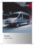
Sprinter
É90658411979ËÍ
9065841197
Order no. 6462 7499 13 Part no. 906 584 11 97 Edition D MY 2013 MB
Sprinter Operator's Manual
Operator's Manual
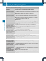
Symbols
Vehicle distributor
G WARNING
Warning notes make you aware dangers
which could pose a threat to your health or
life, or to the health and life of others.
H Environmental note
Environmental notes provide you with
information on environmentally aware actions
or disposal.
! Notes on material damage alert you to
dangers that could lead to damage to your
vehicle.
i These symbols indicate useful
instructions or further information that
could be helpful to you.
This symbol designates an
instruction you must follow.
Several consecutive symbols
X
indicate an instruction with several
steps.
(Y page) This symbol tells you where you
can find further information on a
topic.
This symbol indicates a warning or
YY
an instruction that is continued on
the next page.
Display This text indicates a message on
the display and the rear view
camera monitor.
X
In the USA:
Mercedes-Benz USA, LLC
One Mercedes Drive
Montvale, NJ 07645-0350
www.mbusa.com
www.mbsprinterusa.com
Customer Assistance Center:
1-877-762-8267
In Canada:
Mercedes-Benz Canada, Inc.
98 Vanderhoof Avenue
Toronto, ON M4G 4C9
www.mercedes-benz.ca
Customer Relations Department:
1-800-387-0100
Mercedes-Benz USA, LLC and MercedesBenz Canada Inc. are Daimler companies.
Canada only:
"Authorized Sprinter Dealer" is defined as an
authorized Mercedes-Benz Sprinter Dealer.
Publication details
Internet
Further information on Mercedes-Benz
vehicles can be obtained on the Internet at
www.mercedes-benz.com
www.mbusa.com (USA only)
www.mercedes-benz.ca (Canada only)
Editorial office
You are welcome to forward any queries or
suggestions you may have regarding this
Operator's Manual to the technical
documentation team at the address on the
inside of the front cover.
© Mercedes-Benz USA, LLC
© Mercedes-Benz Canada, Inc.
Mercedes-Benz USA, LLC and MercedesBenz Canada Inc. are Daimler companies.
Not to be reprinted, translated, or otherwise
reproduced, in whole or in part, without
written permission.
Registered trademarks
ESP® is a registered trademark of Daimler AG.
As at 25.05.2012
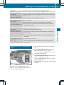
Welcome to the world of Mercedes-Benz
Before you first drive off, read this Operator's
Manual carefully and familiarize yourself with
your vehicle. Please adhere to the information
and warning notes in this Operator's Manual
for your own safety and to ensure a longer
operating duration of the vehicle. Failure to
observe the instructions may lead to damage
to the vehicle or personal injury.
Vehicle damage caused by a failure to
observe the instructions is not covered by the
New Vehicle Limited Warranty.
These Operating Instructions provides
information on the most important functions
of your vehicle.
Your vehicle's equipment or product
designation may vary, depending on the
following:
Rmodel
Rorder
Rcountry
specification
Ravailability
Individual warning and indicator lamps may
not be functional.
We reserve the right to make modifications in
the following areas:
Rdesign
Requipment
Rtechnology
Therefore, the descriptions provided may
occasionally differ from your own vehicle.
The following are integral components of the
vehicle:
ROperator's
Manual
Booklet
Rservice and warranty information
Requipment-dependent operating
instructions
Keep these documents in the vehicle at all
times. Should you sell the vehicle, always
pass the documents on to the new owner.
We wish you pleasant motoring at all times.
RMaintenance
9065841197 É90658411979ËÍ
Contents
Index ....................................................... 4
At a glance ........................................... 31
Introduction ......................................... 22
Safety ................................................... 41
Opening and closing ........................... 63
Seats, steering wheel and mirrors .... 79
Lights and windshield wipers ............ 89
Climate control ................................. 107
Driving and parking .......................... 131
On-board computer and displays .... 175
Stowing and features ....................... 221
Transporting loads ............................ 231
Maintenance and care ...................... 239
Breakdown assistance ..................... 263
Wheels and tires ............................... 273
Technical data ................................... 313
3
4
Index
1, 2, 3 ...
12 V socket ........................................ 228
A
ABS (Anti-lock Braking System)
Display message ............................ 197
Function/notes ................................ 56
Important safety notes .................... 56
Indicator lamp ................................ 210
Accessories and conversions
see Add-on equipment
Activating/deactivating cooling
with air dehumidification ................. 113
Activating/deactivating the roof
ventilator ........................................... 129
Additional indicators
Changing bulbs (roof) .................... 101
Additives
Diesel ............................................ 318
Engine oil ....................................... 322
Flow improver ................................ 318
Add-on equipment ............................... 27
Adjusting
Air vents ........................................ 117
Adjusting the headlamp range ........... 93
ADR (working speed governor) ........ 167
Air bags
Front air bag (driver, front
passenger) ....................................... 45
Important safety notes .................... 44
Safety guidelines ............................. 43
Thoraxbag ........................................ 45
Window curtain air bag .................... 46
Air-conditioning system
Refrigerant ..................................... 326
see Climate control
Air filter
Indicator lamp ................................ 218
Air pressure
see Tire pressure
Air-recirculation mode
Important safety notes .................. 116
Switching on/off ........................... 116
Air vents ............................................. 117
Adjusting for the passenger
compartment ................................. 117
Adjusting on the roof ..................... 118
Important safety notes .................. 117
Setting the center air vents ........... 117
Setting the side air vents ............... 117
see Climate control
Anti-lock Braking System
see ABS (Anti-lock Braking System)
Anti-theft system
Interior motion sensor ..................... 61
Armrests .............................................. 84
Ashtray ............................................... 227
ASR (acceleration skid control)
Activating/deactivating ................... 58
Display message ............................ 198
Function/notes ................................ 58
Important safety notes .................... 58
Indicator lamp ................................ 210
ATA (Anti-Theft Alarm system)
Activating/deactivating ................... 60
Switching off the alarm .................... 60
Attachments
see Add-on equipment
Authorized workshop
see Qualified specialist workshop
Automatic climate control
see Climate control
Automatic headlamp mode ................ 91
Automatic locking ............................... 69
Automatic transmission
Accelerator pedal position ............. 140
Changing gear ............................... 139
Changing gear yourself .................. 139
Driving tips .................................... 140
Emergency running mode .............. 141
Important safety notes .................. 138
Kickdown ....................................... 140
Maneuvering .................................. 140
Overview ........................................ 138
Problem (malfunction) ................... 141
Releasing the parking lock
manually ........................................ 141
Selector lever ................................ 138
Selector lever positions ................. 139
Shift ranges ................................... 140
Starting the engine ........................ 134
Touchshift ...................................... 139
Trailer towing ................................. 140
Transmission oil change ................ 323
Index
Automatic transmission
emergency mode ...............................
Auxiliary heating
Activating/deactivating heater
booster mode ................................
Conditions for switching on ...........
Important safety notes ..................
Operating with the button (control
panel) ............................................
Operation with the remote control .
Operation with the timer ................
Problem (malfunction) ...................
Selecting a switch-on time .............
Setting the switch-on time .............
see Auxiliary heating
Axle load, permissible (trailer
towing) ...............................................
141
125
119
118
119
121
122
128
119
120
329
B
Backup lamps
Changing bulbs ........................ 99, 101
Backup lamps (Chassis Cab)
Changing bulbs .............................. 100
BAS (Brake Assist System)
Display message ............................ 198
Function/notes ................................ 56
Indicator lamp ................................ 210
Basic settings
see Settings
Battery
Isolating switch .............................. 132
Replacing (SmartKey) ................ 66, 67
Battery (SmartKey)
Checking .......................................... 66
Important safety notes .................... 66
Replacing ................................... 66, 67
Battery (vehicle)
Care ............................................... 255
Charge indicator lamp ................... 214
Charging ........................................ 254
Disconnecting and connecting
(driver's footwell) ........................... 251
Disconnecting and connecting
(engine compartment) ................... 253
Display message ............................ 208
Important safety notes .................. 250
Installing/removing (driver's
footwell) ......................................... 252
Installing/removing (engine
compartment) ................................ 254
Jump starting ................................. 267
Location ......................................... 250
Removing/installing the floor
covering (driver's footwell) ............ 251
Belt
see Seat belts
Bio-diesel ........................................... 317
Bleeding the fuel system .................. 137
Bodies
Body/equipment mounting
directives for trucks ......................... 28
Bottle holder ...................................... 227
see Cup holder
Brake
EBD .................................................. 57
Brake Assist System
see BAS (Brake Assist System)
Brake fluid
Checking the level ......................... 245
Display message ............................ 199
Notes ..................................... 245, 324
Warning lamp ................................. 211
Brake force distribution,
electronic
see EBD (electronic brake force
distribution)
Brake lamps
Changing bulbs ........................ 99, 101
Brake lamps (Chassis Cab)
Changing bulbs .............................. 100
Brake linings
Display message ............................ 199
Indicator lamp ................................ 214
Brakes
ABS .................................................. 56
Applying the parking brake ............ 146
BAS .................................................. 56
Brake fluid (notes) ................. 245, 324
Checking brake fluid level .............. 245
Display messages .......................... 199
Driving tips .................................... 150
Important safety notes .................. 150
Maintenance .................................. 210
Parking brake (notes) ..................... 151
5
6
Index
Brake system
Malfunction .................................... 198
Warning lamp ................................. 210
Breakdown
Fire extinguisher ............................ 266
First-aid kit .................................... 266
Jump-starting ................................. 267
Reflective safety jacket .................. 265
Vehicle tool kit ............................... 264
Warning lamp ................................. 265
Warning triangle ............................ 265
see Flat tire
see Towing away
see Tow-starting
Bulb
see Changing bulbs
Bulb failure indicator .......................... 90
C
Care
Car wash ........................................ 256
Display ........................................... 260
Exterior lights ................................ 258
Notes ............................................. 255
Paint .............................................. 257
Plastic trim .................................... 260
Power washer ................................ 257
Rear view camera .......................... 259
Roof lining ...................................... 261
Seat belt ........................................ 261
Seat cover ..................................... 261
Selector lever ................................ 260
Sensors ......................................... 259
Sliding door ................................... 259
Steering wheel ............................... 260
Step (electrical) ............................. 260
Trim pieces .................................... 260
Washing by hand ........................... 256
Washing the engine ....................... 257
Wheels ........................................... 258
Windows ........................................ 257
Wiper blades .................................. 258
Cargo compartment
Activating/deactivating
ventilation ...................................... 129
Cargo compartment floor ................... 28
Cargo tie-down points and tie
downs
Important safety notes .................. 234
Cargo tie-down rings
Installing ........................................ 236
Permissible tensile load ................. 327
Car wash (care) ................................. 256
CD player/CD changer ...................... 183
Cell phone
see Mobile phone
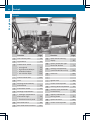
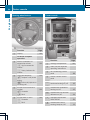
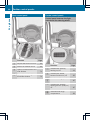
Center console overview .................... 36
Central locking
Automatic locking ............................ 69
Important safety notes .................... 69
Locking/unlocking (buttons) ........... 69
Locking/unlocking (SmartKey) ........ 64
Locking/unlocking manually ............ 69
Central locking system
see Central locking
Changing bulbs
Additional indicators (roof) ............ 101
Additional turn signals ................... 101
Backup lamp (Chassis Cab) ........... 100
Backup lamps .......................... 99, 101
Bi-Xenon bulbs ................................. 96
Brake lamps ............................. 99, 101
Brake lamps (Chassis Cab) ............ 100
Cornering lamps .............................. 98
Courtesy lights ............................... 101
Display message ............................ 201
Fog lamps ........................................ 98
Front interior light .......................... 102
High-beam headlamps ..................... 98
Important safety notes .................... 96
Interior light ................................... 102
Interior lighting .............................. 102
License plate lamp ................ 100, 101
License plate lamp (Chassis Cab) . . 100
Low-beam headlamps ...................... 98
Overview of lamp types (front
bulbs) ............................................... 97
Overview of lamp types (rear
bulbs, Cargo Van/Passenger Van) ... 99
Overview of lamp types (rear
bulbs, Chassis Cab) ....................... 100
Parking lamps .................................. 98
Perimeter lamp .............................. 101
Rear fog lamp .......................... 99, 101
Index
Rear fog lamp (Chassis Cab) .......... 100
Rear interior light ........................... 102
Standing lamps (front) ..................... 98
Standing lamps (rear, Chassis
Cab) ............................................... 100
Standing lamps (rear) .............. 99, 101
Tail lamps ................................ 99, 101
Tail lamps (Chassis Cab) ................ 100
Turn signals (front) ........................... 98
Turn signals (rear, Chassis Cab) ..... 100
Turn signals (rear) .................... 99, 101
Warning and indicator lamps ......... 219
see Replacing bulbs
Child-proof locks
Important safety notes .................... 54
Rear door ......................................... 55
Sliding door ..................................... 55
Children
In the vehicle ................................... 50
Restraint systems ............................ 50
Special seat belt retractor ............... 54
Child seat
LATCH-type (ISOFIX) child seat
anchors ............................................ 52
Top Tether ....................................... 53
Chock ................................................. 147
Cigarette lighter ................................ 227
Cleaning
Mirror turn signal ........................... 259
Trailer tow hitch ............................. 260
Climate control
Air-conditioning system ................. 110
Auxiliary heating ............................ 118
Checking/cleaning the air filter
(rear-compartment air
conditioning) .................................. 248
Cooling with air dehumidification . . 113
Defrosting the windows ................. 114
Heating .......................................... 109
Important safety notes .................. 108
Operating the cargo compartment
air vents ......................................... 129
Overview of systems ...................... 108
Problems with the windshield
heating .......................................... 115
Problem with the rear window
defroster ........................................ 116
Rear-compartment air
conditioning ................................... 112
Rear-compartment heating ............ 111
Reheat function (air
dehumidification) ........................... 114
Setting the air distribution ............. 113
Setting the airflow ......................... 114
Setting the air vents ...................... 117
Setting the temperature ................ 113
Switching air-recirculation mode
on/off ............................................ 116
Switching on/off ........................... 112
Switching the rear window
defroster on/off ............................ 116
Switching windshield heating on/
off .................................................. 115
Cockpit
Overview .......................................... 32
see Instrument cluster
COMAND display
Cleaning ......................................... 260
Combination switch ............................ 92
Communications equipment
Operation ....................................... 229
Type approval/frequency .............. 314
Consumption statistics (on-board
computer) .......................................... 190
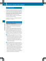
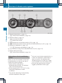
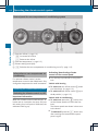
Control panel
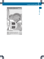
Above the windshield ....................... 37
Center console ................................ 36
Climate control ................................ 36
Driver's door .................................... 38
Left and right side of the steering
wheel ............................................... 38
Conversions/equipment .................... 27
Conversions and accessories
see Add-on equipment
Coolant (engine)
Adding ........................................... 245
Checking the level ......................... 244
Displaying the temperature (onboard computer) ............................ 182
Display message ............................ 205
Filling capacity ............................... 326
Important safety notes .................. 244
Cooling
see Climate control
7
8
Index
Cornering lamps
Changing bulbs ................................ 98
Cornering light function
Function/notes ................................ 93
Courtesy lights
Changing bulbs .............................. 101
Cruise control
Activating ....................................... 156
Activation conditions ..................... 156
Cruise control lever ....................... 155
Deactivating ................................... 157
Display message ............................ 207
Driving system ............................... 155
Function/notes ............................. 155
Important safety notes .................. 155
Problem (malfunction) ................... 157
Resuming the stored speed ........... 156
Setting a speed .............................. 156
Storing and maintaining current
speed ............................................. 156
Cup holders ........................................ 226
Customer Assistance Center (CAC) ... 28
Customer Relations Department ....... 28
D
Dashboard
see Cockpit
Data
see Technical data
Daytime running lamp mode
Setting (vehicles without steeringwheel buttons) ............................... 179
Setting (vehicles with steering
wheel buttons) ............................... 187
Switching on/off (switch) ................ 91
see Daytime running lamps
Declarations of conformity ................. 25
DEF (Diesel Exhaust Fluid )
Refilling .......................................... 143
Defrosting the windshield ................ 114
Delayed switch-off ............................ 188
Diagnostics connection ...................... 25
Diesel .................................................. 317
Diesel engine
Preglow indicator lamp .................. 217
Diesel Exhaust Fluid (DEF)
Display messages (vehicles
without steering wheel buttons) .... 195
Display messages (vehicles with
steering wheel buttons) ................. 204
Exhaust gas aftertreatment ............. 27
Indicator lamp ................................ 213
Information on consumption .......... 321
Level indicator ............................... 178
Notes ............................................. 320
Ranges ............................................. 27
Storage .......................................... 320
Tank content .................................. 321
Diesel particle filter
Short-distance driving .................... 149
Digital speedometer
Setting the unit (vehicles with
steering wheel buttons) ................. 185
Digital speedometer and odometer
Operating safety .............................. 25
Display
Display messages .......................... 192
Outside temperature (vehicles
with steering wheel buttons) ......... 182
Outside temperature display
(vehicles without steering wheel
buttons) ......................................... 178
Standard display (vehicles
without steering wheel buttons) .... 178
Standard display (vehicles with
steering wheel buttons) ................. 182
see Warning and indicator lamps
Display messages
Calling up the message memory .... 193
Driving systems ............................. 207
Engine ............................................ 204
Important safety notes .................. 192
Lights ............................................. 201
Safety systems .............................. 197
SmartKey ....................................... 209
Tires ............................................... 207
Vehicle ........................................... 208
Distance recorder ............................. 182
see Trip odometer
Door lock
see Central locking
Index
Doors
Central locking/unlocking
(SmartKey) ....................................... 64
Control panel ................................... 38
Display message ............................ 209
Indicator lamp ................................ 219
Drinking and driving ......................... 148
Drinks holder
see Bottle holder
see Cup holder
Driver's/co-driver's door
Unlocking ......................................... 70
Driver's seat
see Seats
Driving abroad ................................... 149
Driving off-road
see Off-road driving
Driving on flooded roads .................. 151
Driving safety systems
ABS (Anti-lock Braking System) ....... 56
ASR (Acceleration Skid Control) ...... 58
BAS (Brake Assist System) .............. 56
EBD (electronic brake force
distribution) ..................................... 57
ESP® (Electronic Stability
Program) .......................................... 57
Important safety information ........... 56
Overview .......................................... 56
Driving systems
Cruise control ................................ 155
Display message ............................ 207
PARKTRONIC ................................. 157
Rear view camera .......................... 161
Driving tips
Automatic transmission ................. 140
Brakes ........................................... 150
Break-in period .............................. 132
Downhill gradient ........................... 150
Drinking and driving ....................... 148
Driving abroad ............................... 149
Driving in winter ............................. 152
Driving on flooded roads ................ 151
Driving on wet roads ...................... 151
Exhaust check ............................... 148
Fuel ................................................ 148
General .......................................... 147
Hydroplaning ................................. 151
Icy road surfaces ...........................
Important safety notes ..................
Limited braking efficiency on
salted roads ...................................
Off-road driving ..............................
Overrun cut-off ..............................
Snow chains ..................................
Speed limitation .............................
Towing a trailer ..............................
Transport by rail .............................
Wet road surface ...........................
152
132
151
153
148
277
149
168
150
150
E
EBD (electronic brake force
distribution)
Display message ............................ 200
Function/notes ................................ 57
Indicator lamps .............................. 210
Electrical closing assist ...................... 72
Electrical fuses
see Fuses
Electrical step
Cleaning ......................................... 260
Display message ............................ 208
Emergency release .......................... 72
Function ........................................... 72
Important safety notes .................... 72
Indicator lamp ................................ 219
Manual retraction ............................ 72
Obstacle detection ........................... 72
Electrical system
Battery main switch ....................... 132
Electronic Stability Program
see ESP® (Electronic Stability Program)
Emergency exit .................................... 59
Emergency exit window ..................... 59
Emergency Tensioning Devices
Function ........................................... 50
Safety guidelines ............................. 43
Emissions control
Service and warranty information .... 23
Engine
ADR (working speed governor) ...... 167
Changing the power output ............. 25
Check Engine warning lamp ........... 216
Cleaning instructions ..................... 257
Engine number ............................... 316
9
10
Index
Engine speed setting (working
mode) ............................................ 168
Irregular running ............................ 137
Jump-starting ................................. 267
Operating safety .............................. 25
Starting .......................................... 134
Starting problems .......................... 137
Switching off .................................. 146
Tow-starting (vehicle) ..................... 271
Engine, jump-starting ....................... 267
Engine electronics
Notes ............................................. 314
Problem (malfunction) ................... 137
Engine oil
Adding ........................................... 244
Additives ........................................ 322
Checking the oil level (on-board
computer) ...................................... 242
Checking the oil level using the
dipstick .......................................... 243
Display message ............................ 206
Filling capacity ............................... 323
Information about oil
consumption .................................. 323
Mixing ............................................ 322
Notes about oil grades ................... 321
Oil change ...................................... 322
Oil level (note) ............................... 242
Viscosity ........................................ 321
Warning lamp ................................. 214
Engine speed setting (working
mode) ................................................. 167
Equipment/conversions ..................... 27
ESP® (Electronic Stability
Program)
Display message ............................ 200
Function/notes ................................ 57
Indicator lamp ................................ 213
Warning lamp ................................. 210
Exhaust check ................................... 148
Exhaust gas aftertreatment ............... 27
DEF level indicator ......................... 178
DEF reducing agent ................. 27, 320
Diesel Exhaust Fluid (DEF) ............. 320
Display messages (vehicles
without steering wheel buttons) .... 195
Display messages (vehicles with
steering wheel buttons) ................. 204
Indicator lamp ................................ 213
Malfunction .................................... 204
Refilling DEF .................................. 143
Exterior lighting
Daytime running lamp mode
(vehicles without steering wheel
buttons) ......................................... 179
Daytime running lamp mode
(vehicles with steering wheel
buttons) ......................................... 187
see Lights
Exterior mirrors
Adjusting ......................................... 86
Important safety notes .................... 86
Eyeglasses compartment ................. 223
F
FAME fuel
Bio-diesel ....................................... 317
Fire extinguisher ............................... 266
First-aid kit ......................................... 266
Flat tire
Changing a wheel/mounting the
spare wheel ................................... 303
General notes ................................ 295
Preparing the vehicle ..................... 295
Using tire sealant ........................... 295
Fog lamps
Switching on/off .............................. 91
Folding seat ......................................... 82
Folding table ...................................... 225
Frequencies
Mobile phone ................................. 314
Two-way radio ................................ 314
Front fog lamps
Changing the bulbs .......................... 98
Switching on/off .............................. 91
Front interior light
Changing bulbs .............................. 102
Front windshield
see Windshield
Fuel
Additives (diesel) ........................... 318
Bio-diesel (FAME fuel) .................... 317
Consumption information .............. 319
Consumption statistics .................. 190
Index
Diesel at very low outside
temperatures .................................
Display message ............................
Driving tips ....................................
Flow improver ................................
Fuel gauge .....................................
Important safety notes ..................
Problem (malfunction) ...................
Quality (diesel) ...............................
Refueling ........................................
Showing the range (on-board
computer with steering wheel
buttons) .........................................
Showing the range (vehicles with
steering wheel buttons) .................
Tank content/reserve fuel .............
Fuel filter with water separator
draining .........................................
Indicator lamp ................................
Fuel gauge .........................................
Fuel tank
Problem (malfunction) ...................
Fuel tank content
Reserve, display message ..............
Fuses ..................................................
318
205
148
318
177
317
143
317
142
190
190
317
247
218
177
143
205
271
G
Gasoline
Reserve fuel warning lamp ............. 216
General driving tips
Driving short distances .................. 149
Genuine .............................................. 314
Glove box ........................................... 222
GTW (Gross Trailer Weight)
(definition) ......................................... 293
Guarantee ............................................ 23
H
Hazard warning lamps ........................ 93
Headlamps
Adding fluid to cleaning system ..... 246
Cleaning system (function) .............. 94
Fogging up ....................................... 94
see Automatic headlamp mode
Headliner (cleaning instructions) .... 261
Head restraints
Adjusting ......................................... 84
Heating
see Climate control
High-beam headlamps
Changing bulbs ................................ 98
Switching on/off .............................. 92
Hood
Closing ........................................... 241
Display message ............................ 209
Indicator lamp ................................ 219
Opening ......................................... 240
Hydroplaning ..................................... 151
I
Immobilizer .......................................... 60
Indicator lamp
see Warning and indicator lamps
Indicators
see Turn signals
Insect protection on the radiator ...... 28
Installing/removing the ball
coupling ............................................. 170
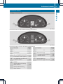
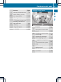
Instrument cluster
Fuel gage ....................................... 177
Important safety notes .................. 176
Instrument cluster lighting ............. 177
Outside temperature display .......... 177
Overview .......................................... 33
Speedometer ................................. 177
Tachometer ................................... 177
Warning and indicator lamps ........... 34
Instrument cluster lighting .............. 177
Instrument lighting
see Instrument cluster lighting
Interior lighting ................................... 94
Changing the bulbs ........................ 102
Front ................................................ 94
Motion detectors ............................. 96
Notes on replacing bulbs ............... 102
Switching the rear compartment
lighting on centrally ......................... 95
Interior motion sensor
Arming ............................................. 61
Deactivating ..................................... 61
Function ........................................... 61
Switching off .................................... 61
11
12
Index
J
Jack
Jacking points ................................
Preparation ....................................
Storage location ............................
Using .............................................
Jump-starting .....................................
304
304
264
304
267
K
Key
Position in the ignition lock ............ 133
see SmartKey
Kickdown ........................................... 140
L
Lamps
see Warning and indicator lamps
Language
Display (vehicles with steering
wheel buttons) ............................... 185
Lashing points and tie downs
Permissible tensile load ................. 327
LATCH-type (ISOFIX) child seat
anchors ................................................ 52
License plate lamp
Changing bulbs ...................... 100, 101
License plate lamp (Chassis Cab)
Changing bulbs .............................. 100
Lighting
see Lights
Lights
Activating/deactivating daytime
running lamp mode (vehicles with
steering wheel buttons) ................... 91
Activating/deactivating surround
lighting (vehicles with steering
wheel buttons) ............................... 187
Automatic headlamp mode .............. 91
Bulb failure indicator ........................ 90
Cornering light function ................... 93
Driving abroad ............................... 149
Fog lamps ........................................ 91
Hazard warning lamps ..................... 93
Headlamp range .............................. 93
High beam flasher ............................ 92
High-beam headlamps ..................... 92
Important safety notes .................... 90
Light switch ..................................... 90
Low-beam headlamps ...................... 90
Parking lamps .................................. 90
Rear fog lamp .................................. 91
Setting the exterior lighting
delayed switch-off (vehicles with
steering wheel buttons) ................. 188
Switching the daytime running
lamp mode on/off (switch) .............. 91
Turn signals ..................................... 92
see Changing a bulb
see Interior lighting
Light sensor ......................................... 91
Limited Warranty ................................ 29
Load distribution ............................... 234
Loading guidelines
Important safety notes .................. 232
Loading rails
Installing cargo tie-down rings ....... 236
Maximum tensile strength ............. 327
Loads
Securing ........................................ 234
Transporting .................................. 232
Load securing aids
Carrier systems ............................. 236
Locator lighting
Setting (vehicles with steering
wheel buttons) ............................... 187
Locking
see Central locking
Locking and unlocking manually ....... 69
Locking centrally
see Central locking
Low-beam headlamps
Changing bulbs ................................ 98
Daytime running lamp mode
(vehicles without steering wheel
buttons) ......................................... 179
Daytime running lamp mode
(vehicles with steering wheel
buttons) ......................................... 187
Display message ............................ 201
Driving abroad ............................... 149
Switching on/off .............................. 90
Lumbar support ................................... 80
Index
M
M+S tires ............................................ 276
Maintenance ...................................... 248
Malfunctions
Message memory (on-board
computer) ...................................... 193
Maximum speed
Speed limitation ............................. 149
Menu (vehicles with steering
wheel buttons)
Audio ............................................. 182
Operation ....................................... 181
Settings ......................................... 183
Telephone ...................................... 190
Message
see Display message
Message memory (on-board
computer) .......................................... 193
Mirrors
Exterior mirrors ................................ 86
Rear-view mirror .............................. 86
Mobile phone
Important safety notes .................. 228
Pre-installation ............................... 229
Type approval/frequency .............. 314
Mounting wheels
Lowering the vehicle ...................... 307
Mounting a new wheel ................... 306
Preparing the vehicle ..................... 303
Raising the vehicle ......................... 304
Removing and mounting the spare
wheel ............................................. 309
Removing a wheel .......................... 306
Securing the vehicle against
rolling away ................................... 303
N
Notes on breaking-in a new
vehicle ................................................ 132
O
Occupant safety
Air bags ........................................... 44
Children in the vehicle ..................... 50
Important safety notes .................... 42
Seat belts ........................................ 47
Odometer
Display (vehicles without steering
wheel buttons) ............................... 178
Display (vehicles with steering
wheel buttons) ............................... 182
see Trip odometer
Off-road driving
Checklist after driving off-road ...... 154
Important safety notes .................. 153
Rules for driving off-road ............... 153
Oil
see Engine oil
On-board computer
Display message ............................ 192
On-board computer (vehicles
without steering wheel buttons)
Display message ............................ 192
General notes ................................ 178
Setting the clock ............................ 179
Standard display ............................ 178
On-board computer (vehicles with
steering wheel buttons)
Audio menu ................................... 182
Display message ............................ 180
Menu overview .............................. 181
Operating ....................................... 180
Operation menu ............................. 181
Settings menu ............................... 183
Standard display ............................ 182
Telephone menu ............................ 190
Trip computer menu ...................... 189
Operating safety
Attachments, bodies, equipment
and conversions ............................... 27
Correct use ...................................... 26
Declaration of conformity ................ 25
Diagnostics connection ................... 25
Digital speedometer and
odometer ......................................... 25
Important safety note ...................... 24
Limited Warranty ............................. 29
Modifying engine output .................. 25
Qualified specialist workshop .......... 26
Radiator cover ................................. 28
Vehicle registration .......................... 23
Warning note sticker ........................ 26
13
14
Index
Operating system
see On-board computer
Operator's Manual
General notes .................................. 23
Vehicle equipment ........................... 23
Outline lamp
Changing bulbs .............................. 101
Outside temperature display ........... 177
Overhead control panel ...................... 37
Overrevving range ............................. 177
Overrun cutoff ................................... 148
P
Paint code number ............................ 315
Paintwork (cleaning instructions) . . . 257
Paper holder ...................................... 225
Parking ............................................... 145
Important safety notes .................. 145
Parking brake ................................ 146
Rear view camera .......................... 161
Wheel chock .................................. 147
see PARKTRONIC
Parking aid
see PARKTRONIC
see Rear view camera
Parking brake
Display message ............................ 201
Notes/function .............................. 146
Parking lamps
Changing bulbs ................................ 98
PARKTRONIC
Deactivating/activating ................. 159
Driving system ............................... 157
Function/notes ............................. 157
Important safety notes .................. 157
Problem (malfunction) ................... 161
Range of the sensors ..................... 157
Roll-back warning .......................... 159
Trailer towing ................................. 160
Warning display ............................. 159
Partition sliding door
Important safety notes .................... 75
Opening/closing .............................. 75
Passenger compartment airconditioning system
see Climate control
Passenger compartment heating
see Climate control
Perimeter lamp
Changing bulbs .............................. 101
Plastic trim (cleaning instructions) . 260
Power supply
Battery isolating switch ................. 132
Switching off .................................. 133
Switching on .................................. 133
Power take-off
Engine speed setting ..................... 167
Power washers .................................. 257
Power windows
see Side windows
Preparing for a journey
Checks in the vehicle ..................... 134
Visual check of the vehicle
exterior .......................................... 134
Product information ............................ 22
Protection of the environment
General notes .................................. 22
Pulling away ...................................... 135
Q
Qualified specialist workshop ........... 26
R
Radiator cover ..................................... 28
Radio
Changing stations (vehicles with
steering wheel buttons) ................. 182
Setting station selection (vehicles
with steering wheel buttons) ......... 188
see separate operating instructions
Radio-based vehicle components
Declaration of conformity ................ 25
Rain and light sensor
Setting the sensitivity (vehicles
with steering wheel buttons) ......... 189
Windshield wiper ........................... 103
Range (vehicles with steering
wheel buttons) .................................. 190
Rear bench seat
Installing/removing (Passenger
Van) ................................................. 83
Stowage compartment (crewcab) . . 224
Index
Rear compartment
Activating/deactivating climate
control ........................................... 112
Setting the air vents ...................... 118
Rear-compartment airconditioning system
see Climate control
Rear-compartment heating
see Climate control
Rear door
Child-proof locks .............................. 55
Important safety notes .................... 73
Opening/closing .............................. 73
Rear fog lamp
Changing bulbs ........................ 99, 101
Switching on/off .............................. 91
Rear fog lamp (Chassis Cab)
Changing bulbs .............................. 100
Rear interior light
Changing bulbs .............................. 102
Rear lamps
see Lights
Rear rack
Notes ............................................. 236
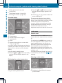
Rear view camera .............................. 161
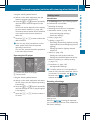
Aspect ratio menu ......................... 165
Brightness submenu ...................... 164
Cleaning instructions ..................... 259
Color submenu .............................. 165
Contrast submenu ......................... 165
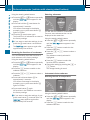
Default settings menu .................... 166
Display menu ................................. 164
Illumination submenu .................... 164
Important safety notes .................. 161
Main menu ..................................... 163
Menu language menu .................... 166
Monitor menu ................................ 163
Problem (malfunction) ................... 167
Standard menu .............................. 165
Switching off the monitor while
driving ............................................ 162
Switching on .................................. 161
Switching the monitor on/off ........ 162
Tint (color balance) submenu ......... 165
Rear-view mirror
Anti-glare mode ............................... 86
Rear window defroster
Problem (malfunction) ................... 116
Switching on/off ........................... 116
Rear window wiper ........................... 104
Refilling
DEF filler neck ............................... 144
Important safety notes (Diesel
Exhaust Fluid – DEF) ...................... 143
Refilling procedure (Diesel
Exhaust Fluid – DEF) ...................... 144
Refrigerant ......................................... 326
Refueling
Fuel filler flap ................................. 142
Fuel gauge ..................................... 177
Important safety notes (fuel) ......... 142
Refueling procedure (fuel) ............. 142
see Fuel
Releasing the parking lock
manually (automatic
transmission) ..................................... 141
Remote control
Changing the operating duration
(auxiliary heating) .......................... 122
Replacing the battery (auxiliary
heating ) ........................................ 126
Switching on/off (auxiliary
heating) ......................................... 121
Synchronizing (auxiliary heating) . . . 122
Replacing the battery (auxiliary
heating remote control) .................... 126
Reporting safety defects .................... 29
Reserve (fuel tank)
see Fuel
Restraint system
see SRS (Supplemental Restraint
System)
Reverse warning feature .................. 136
Roof carrier
Maximum payload .......................... 327
Notes ............................................. 236
Roof load (roof carrier) ..................... 327
15
16
Index
S
Safety
Children in the vehicle ..................... 50
Child restraint systems .................... 50
Safety systems
see Driving safety systems
Seat belts
Adjusting the height ......................... 48
Belt force limiters ............................ 50
Belt warning/warning lamp ............. 49
Cleaning ......................................... 261
Correct usage .................................. 47
Display message ............................ 201
Emergency Tensioning Devices ........ 50
Fastening ......................................... 48
Important safety guidelines ............. 47
Safety guidelines ............................. 43
Warning lamp ................................. 219
Seat heating ......................................... 85
Seats
Adjusting lumbar support ................ 80
Adjusting the co-driver's seat .......... 80
Adjusting the head restraint ............ 84
Armrest ............................................ 84
Cleaning the cover ......................... 261
Folding seat ..................................... 82
Important safety notes .................... 80
Rear bench seat ............................... 83
Seat heating .................................... 85
Setting the driver's seat ................... 80
Swivel seat ....................................... 81
Twin co-driver's seat ........................ 82
Securing loads
Important safety notes .................. 234
Selector lever
Cleaning ......................................... 260
Sensors (cleaning instructions) ....... 259
Service Center
see Qualified specialist workshop
Service interval display
Calling up the service due date ...... 249
Exceeding a service due date ........ 249
Notes ............................................. 249
Service due date (automatic
display) .......................................... 249
Service products
Bio-diesel (FAME fuel) .................... 317
Brake fluid ............................. 245, 324
Coolant (engine) ............................ 324
Diesel ............................................ 317
Diesel Exhaust Fluid (DEF) ............. 320
Engine oil ....................................... 321
Fuel ................................................ 317
Important safety notes .................. 316
Power steering fluid ....................... 323
Refrigerant ..................................... 326
Transmission oil ............................. 323
Washer fluid ................................... 326
Settings
Resetting all (vehicles with
steering wheel buttons) ................. 183
Resetting submenus (vehicles
with steering wheel buttons) ......... 184
Setting the air distribution ............... 113
Setting the airflow ............................ 114
Setting the clock
Vehicles without steering wheel
buttons .......................................... 179
Vehicles with steering wheel
buttons .......................................... 186
Short journeys (diesel particle
filter) ................................................... 149
Side windows
Cleaning ......................................... 257
Hinged side windows ....................... 76
Important safety information ........... 76
Opening/closing .............................. 76
Overview .......................................... 76
Problem (malfunction) ..................... 77
Resetting ......................................... 77
Sliding door
Child-proof locks .............................. 55
Cleaning ......................................... 259
Closing assist ................................... 72
Important safety notes .................... 70
Opening/closing .............................. 70
SmartKey
Changing the battery ................. 66, 67
Changing the locking system
settings .......................................... 189
Checking the battery ....................... 66
Display message ............................ 209
Door central locking/unlocking ....... 64
Index
Important safety notes .................... 64
Loss ................................................. 68
Problem (malfunction) ..................... 68
SmartKey positions (ignition lock) . . 133
Snow chains ...................................... 277
Sockets .............................................. 228
Spare wheel
General notes ................................ 309
Important safety notes .................. 308
Removing/mounting ...................... 309
Specialist workshop ............................ 26
Special seat belt retractor .................. 54
Speed, controlling
see Cruise control
Speedometer
Digital (vehicles without steering
wheel buttons) ............................... 178
Digital (vehicles with steering
wheel buttons) ............................... 186
Selecting display unit (vehicles
with steering- wheel buttons) ........ 185
see Instrument cluster
Sprinter Dealer
see Qualified specialist workshop
SRS (Supplemental Restraint
System)
Display message ............................ 201
Introduction ..................................... 42
Warning lamp ................................. 214
Warning lamp (function) ................... 42
Standing lamps
Changing bulbs (front) ..................... 98
Changing bulbs (rear) .............. 99, 101
Standing lamps (Chassis Cab)
Changing bulbs (rear) .................... 100
Starting (engine) ................................ 134
Start-off assist
Display message ............................ 198
Steering wheel
Adjusting ......................................... 85
Button overview ............................... 36
Cleaning ......................................... 260
Step
see Electrical step
Sticker
Warning notes .................................. 26
Stowage spaces
see Stowage spaces and stowage
compartments
Stowage spaces and stowage
compartments
Eyeglasses compartment ............... 223
Glove box ....................................... 222
Important safety notes .................. 222
Paper holder .................................. 225
Stowage compartment above the
windshield ..................................... 224
Stowage compartment in the
center console ............................... 223
Stowage compartment in the
dashboard ...................................... 223
Stowage space above the
headliner ........................................ 224
Stowage space under the rear
bench seat ..................................... 224
Stowage space under the twin codriver's seat ................................... 224
Summer tires ..................................... 276
Supplemental Restraint System
see SRS (Supplemental Restraint
System)
Switching off the alarm (ATA) ............ 60
Switching the heater booster
function on/off .................................. 125
Switching the surround lighting
on/off (on-board computer) ............. 187
Switch unit
see Control panel
Swivel seat ........................................... 81
T
Tachometer ........................................ 177
Tail lamps
Changing bulbs ........................ 99, 101
see Lights
Tail lamps (Chassis Cab)
Changing bulbs .............................. 100
Tank
see Fuel tank
17
18
Index
Tank content
Fuel gauge ..................................... 177
Range (vehicles with steering
wheel buttons) ............................... 190
Reserve fuel warning lamp ............. 216
Technical data
Capacities ...................................... 316
Cargo tie-down points .................... 327
Cargo tie-down rings ...................... 327
Loading rails .................................. 327
Roof carrier .................................... 327
Tires/wheels ................................. 285
Trailer tow hitch ............................. 328
Vehicle data ................................... 326
Telephone .......................................... 228
Telephone (on-board computer)
Accepting an incoming call ............ 191
Display messages .......................... 209
Numbers from the phone book ...... 191
Operating ....................................... 190
Redialing ........................................ 192
Rejecting or ending a call .............. 191
Temperature
Outside temperature ...................... 177
Setting (climate control) ................ 113
Setting the unit (vehicles with
steering wheel buttons) ................. 184
Theft deterrent systems
ATA (Anti-Theft Alarm system) ......... 60
Immobilizer ...................................... 60
Theft-deterrent systems
Tow-away alarm ............................... 60
Thoraxbag ............................................ 45
Tightening torques for wheel nuts/
wheel bolts ........................................ 307
Time
Setting the time (vehicles without
steering wheel buttons) ................. 179
Setting the time (vehicles with
steering wheel buttons) ................. 186
Timer
Activating ....................................... 123
Important safety notes .................. 122
Overview ........................................ 123
Setting the heating level (auxiliary
heating) ......................................... 125
Setting the preselection time
(auxiliary heating) .......................... 124
Setting weekday, time and
operating duration (auxiliary
heating) ......................................... 123
Switching immediate heating
mode on/off (auxiliary heating) ..... 124
Tire pressure
Calling up (on-board computer) ..... 281
Checking manually ........................ 280
Display messages (vehicles
without steering wheel buttons) .... 194
Display messages (vehicles with
steering wheel buttons) ................. 207
Maximum ....................................... 280
Notes ............................................. 279
Not reached (tire sealant) .............. 301
Reached (tire sealant) .................... 301
Recommended ............................... 278
Setting the unit (vehicles with
steering wheel buttons) ................. 186
Tire label ................................ 278, 279
Tire pressure loss warning system . 282
Tire pressure monitor
Display message ............................ 207
Indicator lamp ................................ 218
Tire pressure monitoring system
Checking the tire pressure
electronically ................................. 282
Function/notes ............................. 281
Restarting ...................................... 283
Warning lamp ................................. 282
Tire pressure table ............................ 285
Tires
Aspect ratio (definition) ................. 294
Average weight of the vehicle
occupants (definition) .................... 293
Bar (definition) ............................... 292
Changing a wheel .......................... 302
Characteristics .............................. 292
Checking ........................................ 275
Definition of terms ......................... 292
Direction of rotation ...................... 303
Distribution of the vehicle
occupants (definition) .................... 295
DOT, Tire Identification Number
(TIN) ............................................... 292
DOT (Department of
Transportation) (definition) ............ 293
Index
GAWR (Gross Axle Weight Rating)
(definition) .....................................
GTW (Gross Trailer Weight)
(definition) .....................................
GVW (Gross Vehicle Weight)
(definition) .....................................
GVWR (Gross Vehicle Weight
Rating) (definition) .........................
Important safety notes ..................
Increased vehicle weight due to
optional equipment (definition) ......
Kilopascal (kPa) (definition) ...........
Labeling (overview) ........................
Load bearing index (definition) ......
Load index .....................................
Load index (definition) ...................
M+S tires .......................................
Maximum loaded vehicle weight
(definition) .....................................
Maximum load on a tire
(definition) .....................................
Maximum permissible tire
pressure (definition) .......................
Maximum tire load .........................
Maximum tire load (definition) .......
Optional equipment weight
(definition) .....................................
PSI (pounds per square inch)
(definition) .....................................
Replacing .......................................
Service life .....................................
Sidewall (definition) .......................
Speed rating (definition) ................
Storing ...........................................
Structure and characteristics
(definition) .....................................
Summer tires .................................
TIN (Tire Identification Number)
(definition) .....................................
Tire bead (definition) ......................
Tire pressure (definition) ................
Tire pressures (recommended) ......
Tire size (data) ...............................
Tire size designation, load-bearing
capacity, speed rating ....................
Tire tread .......................................
Tire tread (definition) .....................
Total load limit (definition) .............
293
293
293
293
274
293
293
289
294
291
294
276
293
294
294
291
294
294
294
302
276
294
293
303
292
276
294
294
294
293
285
290
275
294
295
Traction (definition) ....................... 295
TWR (permissible trailer drawbar
noseweight) (definition) ................. 295
Uniform Tire Quality Grading
Standards (definition) .................... 293
Unladen weight (definition) ............ 294
valve, Snap-In ................................ 280
Wear indicator (definition) ............. 295
Wheel rim (definition) .................... 293
Tire sealant
Storage location ............................ 265
Using ............................................. 295
Top Tether ............................................ 53
Touchshift (automatic
transmission) ..................................... 139
Tow-away alarm
Arming/deactivating ........................ 61
Deactivating ..................................... 61
Operation ......................................... 60
Towing
If the vehicle is stuck ..................... 270
Important safety guidelines ........... 268
Installing/removing the towing
eye ................................................. 269
In the event of malfunctions .......... 269
With a raised front or rear axle ...... 269
Towing a trailer
Axle load, permissible .................... 329
Cleaning the trailer tow hitch ......... 260
Coupling up a trailer ...................... 171
Decoupling a trailer ....................... 172
Driving tips .................................... 168
Important safety notes .................. 168
Installing and removing the ball
coupling ......................................... 170
Notes on retrofitting ...................... 328
Power supply ................................. 174
Trailer loads ................................... 329
Towing away
With both axles on the ground ....... 270
Tow-starting
Emergency engine starting ............ 271
Important safety notes .................. 268
Trailer
Brake force booster malfunction . . . 211
Trailer coupling
see Towing a trailer
see Trailer tow hitch
19
20
Index
Trailer loads and drawbar
noseweights ...................................... 173
Trailer towing
PARKTRONIC ................................. 160
Permissible trailer loads and
drawbar noseweights ............ 169, 173
Transmission
see Automatic transmission
Transmission oil ................................ 323
Transport
Loading guidelines ......................... 232
Vehicle ........................................... 271
Transportation
Rail ................................................ 150
Transport by rail ................................ 150
Transporting
Load distribution ............................ 234
Securing a load .............................. 234
Trim pieces (cleaning instructions) . 260
Trip computer (on-board
computer) .......................................... 189
Trip meter
see Trip odometer
Trip odometer
Display (vehicles without steering
wheel buttons) ............................... 178
Display (vehicles with steering
wheel buttons) ............................... 182
Resetting ....................................... 177
see Trip computer (on-board computer)
Turn signals
Changing bulbs (front) ..................... 98
Changing bulbs (rear) .............. 99, 101
Switching on/off .............................. 92
Turn signals (Chassis Cab)
Changing bulbs (rear) .................... 100
Twin co-driver's seat
Folding table .................................. 225
Stowage compartment .................. 224
Two-way radios
Type approval/frequency .............. 314
TWR (Tongue Weight Rating)
(definition) ......................................... 295
U
Unlocking
From inside the vehicle (central
unlocking button) ............................. 69
V
Vehicle
Correct use ...................................... 26
Data acquisition ............................... 29
Display message ............................ 208
Electronics ..................................... 314
Equipment ....................................... 23
Individual settings (vehicles with
steering wheel buttons) ................. 183
Limited Warranty ............................. 29
Loading .......................................... 286
Locking (SmartKey) .......................... 64
Lowering ........................................ 307
Maintenance .................................... 23
Operating safety .............................. 24
Parking for a long period ................ 147
Pulling away ................................... 135
Raising ........................................... 304
Registration ..................................... 23
Reporting problems ......................... 28
Securing from rolling away ............ 145
Towing away .................................. 268
Transporting .................................. 271
Unlocking (SmartKey) ...................... 64
Vehicle battery
see Battery (vehicle)
Vehicle bodies
General notes .................................. 27
Vehicle data ....................................... 326
Vehicle identification number .......... 315
Vehicle identification plate .............. 315
Vehicle tool kit .................................. 264
Voltage supply
Fuses ............................................. 271
W
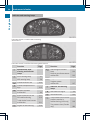
Warning and indicator lamps
Brakes ...........................................
Check Engine .................................
Coolant ..........................................
Diesel Exhaust Fluid (DEF) .............
211
216
215
213
Index
Electrical step ................................ 219
ESP® .............................................. 210
ESP® function ................................ 213
Overview .......................................... 34
Seat belt ........................................ 219
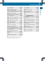
Warning- and indicator lamps
ABS ................................................ 210
Air filter .......................................... 218
ASR ................................................ 210
BAS ................................................ 210
Battery charge ............................... 214
Brake wear .................................... 214
Bulbs .............................................. 219
Doors ............................................. 219
Engine oil level ............................... 214
Preglow .......................................... 217
Reserve fuel ................................... 216
Tire pressure monitor .................... 218
Water separator ............................. 218
Windshield washer fluid ................. 219
Warning lamp .................................... 265
Warning triangle ................................ 265
Washer fluid
Adding ........................................... 246
Capacities ...................................... 326
Display message ............................ 209
Indicator lamp ................................ 219
Notes ............................................. 326
Wiping with .................................... 103
Wheels
Changing a wheel .......................... 302
Checking ........................................ 275
Cleaning ......................................... 258
Important safety notes .................. 274
Interchanging/changing ................ 302
Mounting a wheel .......................... 303
Removing and mounting the spare
wheel ............................................. 309
Storing ........................................... 303
Tightening torque ........................... 307
Window curtain air bag ....................... 46
Windows
see Side windows
Windshield heating
Problem (malfunction) ................... 115
Switching on/off ........................... 115
Windshield washer fluid
Adding ........................................... 246
Indicator lamp ................................ 219
Windshield wipers
Problem (malfunction) ................... 105
Rain and light sensor ..................... 103
Rear window wiper ........................ 104
Replacing the wiper blades .... 103, 104
Setting the sensitivity (vehicles
with steering wheel buttons and
rain/light sensor) ........................... 189
Switching on/off ........................... 103
Wiping with windshield washer
fluid ............................................... 103
Winter diesel ..................................... 318
Winter driving
Slippery road surfaces ................... 152
Snow chains .................................. 277
Winter operation
General notes ................................ 276
Radiator cover ................................. 28
Winter tires
M+S tires ....................................... 276
Setting a limit speed ...................... 149
Wiper blades
Cleaning ......................................... 258
Replacing ....................................... 104
Workshop
see Qualified specialist workshop
21
22
Introduction
Protection of the environment
General notes
H Environmental note
Daimler's declared policy is one of
comprehensive environmental protection.
The objectives are for the natural resources
that form the basis of our existence on this
planet to be used sparingly and in a manner
that takes the requirements of both nature
and humanity into account.
You too can help to protect the environment
by operating your vehicle in an
environmentally responsible manner.
Fuel consumption and the rate of engine,
transmission, brake and tire wear are affected
by these factors:
Roperating
conditions of your vehicle
personal driving style
You can influence both factors. You should
bear the following in mind:
Operating conditions:
Ryour
Ravoid
short trips as these increase fuel
consumption.
Ralways make sure that the tire pressures
are correct.
Rdo not carry any unnecessary weight.
Rremove roof racks once you no longer need
them.
Ra regularly serviced vehicle will contribute
to environmental protection. You should
therefore adhere to the service intervals.
Ralways have service work carried out at a
qualified specialist workshop.
Personal driving style:
Rdo not depress the accelerator pedal when
starting the engine.
Rdo not warm up the engine when the vehicle
is stationary.
Rdrive carefully and maintain a safe distance
from the vehicle in front.
frequent, sudden acceleration and
braking.
Ravoid
Rchange gear in good time and use each gear
only up to Ô of its maximum engine speed.
Rswitch
off the engine in stationary traffic.
an eye on the vehicle's fuel
consumption.
Rkeep
Environmental issues and
recommendations
When prompted by this Operator's Manual to
dispose of materials, please try to regenerate
and recycle these materials. Observe all
relevant environmental guidelines and
regulations when disposing of materials. This
helps to protect the environment.
Product information
We recommend original Sprinter parts and
conversion parts and accessories that have
been approved expressly for the type of
vehicle concerned.
We test genuine Sprinter parts, as well as
conversion parts and accessories that have
been specifically approved for the type of
vehicle, for:
Rreliability
Rsafety
Rsuitability
Despite ongoing market research, we are
unable to assess other parts. We therefore
accept no responsibility for the use of such
parts in a Sprinter, even if they have been
independently or officially approved.
Genuine Sprinter parts, as well as specifically
approved conversion parts and accessories,
can be obtained at an authorized Sprinter
Dealer. Here you will receive advice about
permissible technical modifications, and the
parts will be professionally installed.
Introduction
Operator's Manual
Service and vehicle operation
General notes
Maintenance and literature
Before you first drive off, read this Operator's
Manual carefully and familiarize yourself with
your vehicle.
Please adhere to the information and warning
notes in this Operator's Manual for your own
safety and to ensure a longer operating
duration of the vehicle. Failure to observe the
instructions may lead to damage to the
vehicle or personal injury.
Damage to the vehicle, caused by not
adhering to the instructions, is not covered by
the New Vehicle Limited Warranty .
Vehicle equipment
The Operator's Manual describes all models
and standard and optional equipment of your
vehicle that were available at the time of
going to print. Country-specific variations are
possible. Note that your vehicle may not be
equipped with all of the described functions.
This also applies to systems and functions
relevant to safety. The equipment in your
vehicle may therefore differ from that shown
in the descriptions and illustrations. The
original purchase contract documentation for
your vehicle contains a list of all of the
systems in your vehicle.
If you have questions about equipment and
operation, consult any authorized Sprinter
Dealer.
The Operator's Manual, the Maintenance
Booklet and the equipment-dependent
operating instructions are important
documents and should be kept in the vehicle.
The Service and Warranty Information
Booklet contains detailed information on the
types of warranty that your Sprinter is
covered by, including:
RNew
Vehicle Limited Warranty
Engine Limited Warranty
RAnti-Perforation Warranty
RLimited Warranty for Restraint Systems
(only vehicles that have been sold and
registered in the state of Kansas)
RLegally required Emission Performance
Warranty
Replacement parts and accessories are
subject to the Replacement Part and
Accessory Warranty of the dealer mentioned
on the inside cover. You can obtain these
from any authorized Sprinter dealer.
RDiesel
Maintenance
The Maintenance Booklet and the Service and
Warranty Information Booklet describe all
necessary maintenance work that should be
carried out at regular intervals.
When you take the vehicle to an authorized
Sprinter dealer, always be sure to bring the
Maintenance/Service/Warranty Information
Booklet. Your customer service advisor
enters each maintenance service into the
Maintenance Booklet for you.
Registering your vehicle
We may ask our authorized Sprinter Dealers
to carry out technical inspections on certain
vehicles to improve their quality or safety.
We can only inform you about vehicle checks
if we have your registration data.
Z
23
24
Introduction
Your registration data is not stored if:
Ryou
did not purchase your vehicle at an
authorized Sprinter Dealer.
Ryour vehicle has never been inspected at
an authorized Sprinter Dealer.
It is advisable to register your vehicle with an
authorized Sprinter Dealer. Please inform us
as soon as possible about any change of
address or vehicle ownership.
Operating safety
Important safety notes
G WARNING
Exhaust fumes, some of its constituents, and
certain vehicle components contain or emit
chemicals known to the State of California to
cause cancer and birth defects or other
heritable genetic damage.
In addition, certain fluids contained in
vehicles, and certain products that are used
as components, contain chemicals known to
the State of California to cause cancer and
birth defects or other heritable genetic
damage.
Air bags and pyrotechnic Emergency
Tensioning Devices (ETDs) and remote
control batteries contain perchlorate
material, which may require special handling
and regard for the environment. Check with
your local government's disposal guidelines.
In California, see www.dtsc.ca.gov/
HazardousWaste/Perchlorate/ index.cfm.
G WARNING
If you do not have the prescribed service/
maintenance work or any required repairs
carried out, this can result in malfunctions or
system failures. There is a risk of an accident.
Always have the prescribed service/
maintenance work as well as any required
repairs carried out at a qualified specialist
workshop.
G WARNING
Modifications to electronic components, their
software as well as wiring can impair their
function and/or the function of other
networked components. In particular,
systems relevant to safety could also be
affected. As a result, these may no longer
function as intended and/or jeopardize the
operating safety of the vehicle. There is an
increased risk of an accident and injury.
Never tamper with the wiring as well as
electronic components or their software. You
should have all work to electrical and
electronic equipment carried out at a qualified
specialist workshop.
G WARNING
Flammable materials, e.g. leaves, grass or
branches, may ignite if they come into contact
with hot parts of the exhaust system for
extended periods. There is a risk of fire.
When driving off-road or on unpaved surfaces,
check the underside of the vehicle at regular
intervals. In particular, remove any trapped
parts of plants or other flammable material. If
there is any damage, inform a qualified
specialist workshop.
The general operating permit for your vehicle
could be rendered invalid If you carry out
modifications to electronic components,
their software as well as wiring.
Driving off-road or on construction sites
increases the possibility of vehicle damage
which may in turn lead to the failure of certain
assemblies and systems.
There is a risk of damage to the vehicle if:
Rthe vehicle makes contact with the ground,
e.g. on a high curb or a loose road surface
drive too quickly over an obstacle, e.g.
a curb or a pothole
Ra heavy object hits the underbody or
chassis component
In these or similar situations, the vehicle
body, the underbody, chassis components,
wheels or tires could be damaged even if this
Ryou
Introduction
is not visible from the outside. Components
that have been damaged in this way can
unexpectedly fail or no longer be able to
assimilate the loads occurring in the event of
an accident. If the underbody paneling is
damaged, flammable material, such as
leaves, grass or twigs, could collect between
the underbody and underbody paneling.
These materials could ignite if they remain in
contact with hot components of the exhaust
system for an extended period. Have the
vehicle checked and repaired immediately at
a qualified specialist workshop. If you
become aware when continuing the journey
that driving safety has been effected, stop as
soon as possible in accordance with the
traffic conditions. In such cases, consult a
qualified specialist workshop. Adapt your
driving style to the off-road driving conditions.
Drive carefully. Have any vehicle damage
rectified at a qualified specialist workshop as
soon as possible.
Declaration of conformity
Radio-based vehicle components
USA: "The wireless devices of this vehicle
comply with Part 15 of the FCC Rules.
Operation is subject to the following two
conditions: 1) These devices may not cause
harmful interference, and 2. These devices
must accept any interference received,
including interference that may cause
undesired operation. Changes or
modifications not expressly approved by the
party responsible for compliance could void
the user’s authority to operate the
equipment."
Canada: "The wireless devices of this vehicle
comply with Industry Canada license-exempt
RSS standard(s). Operation is subject to the
following two conditions: 1) These devices
may not cause harmful interference, and 2)
These devices must accept any interference
received, including interference that may
cause undesired operation of the device".
Digital speedometer and odometer
Do not modify the vehicle's electronically
stored odometer by tampering with the
electronics.
If you sell your vehicle, inform the buyer about
any changes to the total distance reading, for
example after replacing the speedometer.
Failure to do so may constitute a punishable
offense under national legislation.
Changing the engine power output
! Increases in engine power can:
Rchange
the emission values
malfunctions
Rcause consequential damage
The operating reliability of the engine is not
guaranteed in all cases.
Rcause
Any tampering with the engine management
system in order to increase the engine power
output will lead to the loss of the New Vehicle
Limited Warranty and other warranty
entitlements.
If you sell the vehicle, inform the purchaser
about the changes to the engine power
output of the vehicle. If you do not inform the
buyer, this may constitute a punishable
offense under national legislation.
Diagnostics connections
All diagnostics connections are only intended
for the connection of diagnostic equipment at
a qualified specialist workshop.
G WARNING
If you connect equipment to the diagnostics
connection in the vehicle, it may affect the
operation of the vehicle systems. As a result,
the operating safety of the vehicle could be
affected. There is a risk of an accident.
Do not connect any equipment to a
diagnostics connection in the vehicle.
Z
25
26
Introduction
G WARNING
Objects in the driver's footwell can restrict the
pedal travel or obstruct a depressed pedal.
The operating and road safety of the vehicle
is jeopardized. There is a risk of an accident.
Make sure that all objects in the vehicle are
stowed correctly, and that they cannot enter
the driver's footwell. Install the floormats
securely and as specified in order to ensure
sufficient clearance for the pedals. Do not use
loose floormats.
! If the engine is switched off and a device
which is connected to the on-board
diagnostics connection is being used, the
battery may discharge.
Connecting equipment to the diagnostics
connections can lead to emissions
monitoring information being reset. The
possible outcome may be that the vehicle no
longer fulfills the emissions laws and
regulations. This may be a criminal offense or
breach of road traffic regulations in certain
countries.
For this reason, we recommend an authorized
Sprinter Dealer.
Proper use
G WARNING
Gases and fluids from substances that
constitute a health hazard or react
aggressively can escape even from securely
closed containers. When transporting such
substances in the vehicle interior, your ability
to concentrate or your health could be
affected during the journey. Malfunctions,
short circuits or electrical component system
failures may also result. There is a risk of an
accident and fire.
Do not store or transport any substances in
the vehicle interior which are hazardous to
health or react aggressively.
Do not store or transport any substances in
the vehicle interior which are hazardous to
health or react aggressively.
These include:
Rsolvents
Qualified specialist workshops
An authorized Sprinter Dealer is a qualified
specialist workshop. A qualified specialist
workshop has the necessary specialist
knowledge, tools and qualifications to
correctly carry out the work required on the
vehicle. This is especially the case for work
relevant to safety.
Observe the information in the Maintenance
Booklet.
The following work should always be carried
out at qualified specialist workshop:
Rwork
relevant to safety
Rservice and maintenance work
Rrepair work
Rmodifications as well as installations and
alterations
Rwork on electronic components
Rfuel
Roils
and greases
agents
Racids
There are various warning stickers affixed to
your vehicle. If you remove warning stickers,
others may fail to recognize the dangers.
Leave the warning stickers in their original
position.
Observe the following information when
operating your vehicle:
Rcleaning
Rthe safety information in these instructions
Rthe
“Technical data“ section in this
Operator's Manual
Rtraffic rules and regulations
Rmotor vehicle laws and safety standards
Introduction
Exhaust gas aftertreatment
The exhaust gas aftertreatment requires a
reducing agent known as Diesel Exhaust Fluid
(DEF) in order to function correctly. Filling up
the DEF tank is usually part of the service
scope. DEF consumption depends on
operational and driving conditions and it is
not necessary to wait until the next scheduled
service to replenish the fluid. Fluid should be
added regularly to the DEF supply reservoir
during vehicle operation or, at the latest, after
receiving the first warning message via the
on-board computer.
To conform to emission regulations, you must
operate the vehicle with DEF and refill the
supply regularly. The engine management
recognizes attempts to operate the vehicle
without DEF, with thinned DEF or with
another reducing agent. After previous
warning messages, the engine management
then prevents a further engine start.
If the DEF level drops below 1.5 US gal
(5.5 l), the first warning message is issued
and a warning tone sounds. After the
message appears for the first time, and under
normal driving conditions, the remaining DEF
supply will last for approximately 1,000 mi
(1,600 km).
After that, the 0.8 US gal (3.0 l) reserve mark
is reached. Once the reserve range has been
reached, you will receive the next warning
message and you will hear a series of warning
tones. After the first message, the DEF
reserve will last for approximately 1,200 mi
(1,900 km). However, you will only be able to
start the engine another 16 times.
You should immediately add 2.0 US gal
(7.6 l) of DEF (Y page 144) or have the DEF
supply reservoir filled at a qualified specialist
workshop.
When the number of remaining engine starts
is 0, the engine management prevents the
engine being started.
If the ; check engine indicator lamp lights
up, the exhaust gas aftertreatment is faulty or
an emission-related malfunction has
occurred (Y page 204). You will then only be
able to drive a maximum 50 mi (80 km) before
the engine management restricts the number
of starts remaining.
If the exhaust gas aftertreatment is faulty,
have it checked and repaired at a qualified
specialist workshop.
Further information on DEF can be found in
the "Refueling" (Y page 143) and "Service
products and capacities" (Y page 320)
sections.
Attachments, bodies, equipment and
conversions
General notes
! For safety reasons, have add-on
equipment manufactured and installed
according to the Sprinter body/equipment
mounting directives in force. These body/
equipment mounting directives ensure that
the chassis and the body form one unit and
that maximum operating and road safety is
achieved.
We recommend for safety reasons that:
Ryou
carry out no other modifications to
the vehicle.
Ryou obtain the agreement of the
distributor named on the inside of the
front cover for any deviations from the
approved body/equipment mounting
directives.
Approval from certified inspection
agencies or official approvals cannot rule
out risks to your safety.
We recommend that you use genuine
Mercedes-Benz parts as well as conversion
parts and accessories that have been
specifically approved by Mercedes-Benz for
the type of vehicle.
These parts have been specially tested to
establish their safety, reliability and
suitability.
Z
27
28
Introduction
Further information can be obtained at any
authorized Sprinter Dealer.
Notes on the radiator
Even seemingly small changes to the vehicle,
such as attaching a radiator trim for winter
driving, is not permitted. Do not cover up the
radiator. Do not use thermal mats, insect
protection covers or anything similar.
Otherwise, the values of the diagnostic
system may be affected. Some of these
values are legally prescribed and must always
be correct.
Information on the cargo compartment
floor
! The wooden or plastic cargo area floor
fitted at the factory is an integral
component of the vehicle structure. The
vehicle body could be damaged if you have
the load area floor removed. This then
affects the securing of loads and the
maximum loading capacity of the lashing
points is no longer guaranteed.
Therefore, do not have the load area floor
removed.
Sprinter body/equipment mounting
directives
G WARNING
The function of systems or components can
be affected by conversions or modifications
to the vehicle. They might not function
properly any more and/or jeopardize the
operational safety of the vehicle. There is an
increased risk of an accident and injury.
Conversions or modifications should always
be carried out at qualified specialist
workshop.
If you intend to make modifications to your
vehicle, we strongly recommend that you
contact the distributor named on the inside
of the front cover. There you will receive all
the necessary information and a charge may
be levied.
You alone accept the responsibility if body
manufacturers or dealers make modifications
that affect the final certification of the engine,
the vehicle or the equipment. This also
applies to the identification and
documentation of modifications to the
affected vehicle components.
You are responsible for certification and
confirmation that:
Rall the applicable standards and regulations
that are affected by the vehicle
modification are met
Rthe modified vehicle fulfills the vehicle
safety standards and emissions laws and
regulations
Rthe modifications or installation of
accessories does not affect the safety of
the vehicle.
We are not responsible for the final
certification, product liability or warranty
claims which result from the modifications.
This applies to:
Rthe
modified components, assemblies or
systems
Rany resulting noncompliance with any of
the emissions laws and regulations or the
motor vehicle safety standards
Rany consequences arising from the
changes that make the vehicle less safe or
even render it defective
We do not assume responsibility as the finalstage manufacturer or for the consequential
product liability.
Problems with your vehicle
If you should experience a problem with your
vehicle, particularly one that you believe may
affect its safe operation, we urge you to
contact an authorized Sprinter Dealer
immediately to have the problem diagnosed
and rectified.
Introduction
If the problem cannot be rectified to your
satisfaction there:
Rplease
discuss the problem with a
management representative from the
authorized Sprinter Dealer.
Rif necessary, contact the distributor named
on the inside of the front cover.
Reporting safety defects
USA only:
The following text is reproduced as required
of all manufacturers according to Title 49,
Code of U.S. Federal Regulations, Part 575
pursuant to the National Traffic and Motor
Vehicle Safety Act of 1966.
If you believe that your vehicle has a defect
which could cause a crash or could cause
injury or death, you should immediately
inform the National Highway Traffic Safety
Administration (NHTSA) in addition to
notifying the vehicle distributor named on the
inside of the front cover.
If NHTSA receives similar complaints, it may
open an investigation, and if it finds that a
safety defect exists in a group of vehicles, it
may order a recall and remedy campaign.
However, NHTSA cannot become involved in
individual problems between you, your
dealer, or the vehicle distributor.
To contact NHTSA, you may either call the
Vehicle Safety Hotline toll-free at
1-888-327-4236(TTY: 1-800-424-9153);
or go to http://www.safercar.gov;
or write to:
Administrator, NHTSA, 400 Seventh Street
SW, Washington, DC 20590.
You can find more information on vehicle
safety at:
http://www.safercar.gov
Canada only:
If you believe that your vehicle has a safety
defect, you should contact immediately the
Customer Service Department of the vehicle
distributor named on the inside of the front
cover.
Limited Warranty
! Follow the instructions in this Operator's
Manual about the proper operation of your
vehicle as well as about possible vehicle
damage. Damage to your vehicle that
arises from culpable contravention of these
instructions is not covered by the Limited
Warranty of the distributor named on the
inside of the front cover.
Data stored in the vehicle
Information about electronic data
acquisition in the vehicle
(Including notice pursuant to California Code
§ 9951)
Please note that your vehicle is equipped with
devices that can record vehicle systems data.
This information helps, for example, to test
vehicle systems after an accident and to
continually improve vehicle safety. We can
access this data and submit it:
Rfor
safety research or vehicle diagnosis
purposes
Rwith the consent of the vehicle owner or
lessee
Ron the instruction of prosecuting
authorities or other governmental agencies
Rfor use in arbitration of disputes that
involve the manufacturer, its affiliates or its
sales and service organizations
Ras otherwise required or permitted by law.
Data for multimedia devices
Depending on the equipment level, your
vehicle may feature communications and/or
entertainment systems (e.g. telephone
systems). The data necessary for the
Z
29
30
Introduction
operation of the multimedia devices can be
stored and edited on the devices themselves.
Further information on operation (e.g. on
deleting data) can be found in the separate
operating instructions.
Cockpit .................................................
Instrument cluster ..............................
Steering wheel buttons ......................
Center console ....................................
Overhead control panel ......................
Door control panel ..............................
Further control panels ........................
32
33
36
36
37
38
38
At a glance
31
32
Cockpit
At a glance
Cockpit
Function
Page
:
Door control panel
38
;
Light switch
90
=
Combination switch
• turn signals
• high-beam headlamps
• windshield wipers
• rear window wiper
92
92
103
104
?
Cruise control lever
155
A
Horn
B
Steering wheel without/
with buttons
36
C
Instrument cluster
33
D
Stowage compartment
E
• Stowage compartment
with interior light
• Overhead control panel
F
Rear-view mirror
G
Rear view camera monitor
Function
Page
H
PARKTRONIC warning
display
I
Opens/closes the righthand side window
76
J
Stowage compartment
(jack and vehicle tool kit)
264
K
Glove box
222
L
Center console
M
Ignition lock
N
Further control panels
38
O
Steering wheel adjustment
85
P
Selector lever (automatic
transmission)
138
Q
94
37
Applies/releases the
parking brake
151
R
Opens the hood
240
86
S
Further control panels
161
157
36
133
38
Instrument cluster
33
Instrument cluster
At a glance
Displays and controls
Instrument cluster on vehicles without steering wheel buttons
Instrument cluster in vehicles with steering-wheel buttons
Function
Page
Function
Page
:
Speedometer
177
B
Reset button 9
;
Tachometer
177
C
=
f, g Brightens/dims the
instrument cluster lighting
Menu button 4
• changes standard display
• selects menus
178
179
Service button Ë
Checks the engine oil level
242
?
A
Fuel gage with fuel filler flap
location indicator
Display
Vehicles without steering
wheel buttons
Vehicles with steering
wheel buttons
177
D
177
178
33
34
Instrument cluster
At a glance
Indicator and warning lamps
Instrument cluster on vehicles without steering
wheel buttons
Instrument cluster in vehicles with steering-wheel buttons
Function
:
Page
Speedometer with
warning and indicator
lamps
d ESP® warning lamp
ASR warning lamp
57
58
% Coolant level too low
215
? Coolant temperature too
high
215
+ Restraint systems
malfunction
42
b Brake fluid level too low
EBD malfunctioning
Trailer brake force booster
malfunction
211
210
4 Engine oil level warning
214
211
Function
; Check engine indicator
lamp
Exhaust gas aftertreatment
malfunction
% Preglow
Preglow system
malfunction
;
Page
216
213
134
217
Indicator and warning
lamps
G Left-hand turn signal
92
! ABS malfunction
210
h Tire pressure loss or the tire
pressure monitor is
malfunctioning (USA only)
Tire pressure loss (Canada
only)
218
282
Function
¦ Fluid level too low in
windshield washer/
headlamp cleaning system
Page
219
Function
Page
: Water in the fuel
218
# Battery charging
malfunction
214
b Bulb defective
219
1 Door or hood open
Electrically operated step
malfunction
219
# Brake pads/linings worn
214
K High-beam headlamps on
92
J Right-hand turn signal
c Parking brake applied
92
L Low-beam headlamps on
90
58
210
K Working speed governor
(ADR) on
167
57
K High-beam headlamps on
92
: ASR malfunction
BAS malfunction
h
ESP®
malfunction
å DEF supply low or
contaminated/thinned
Exhaust gas aftertreatment
malfunction
219
Tachometer with
warning and indicator
lamps
151
178
| Reserve fuel
Fuel filler cap open
216
216
213
h ESP® malfunction
210
7 Fasten seat belts
219
È Dirt accumulation in air
filter
218
6 Reserve fuel
Fuel filler cap open
177
216
i Corresponding messages may also be
shown in the display (Y page 192).
=
35
At a glance
Instrument cluster
36
Center console
Center console
At a glance
Steering wheel buttons
Function
:
Display
Page
180
On-board computer
operation
;
=
?
A
Selects a submenu or
adjusts the volume
W Up/increases the
volume
X Down/reduces the
volume
Using the telephone
6 Accepts a call/starts
dialing
~ Ends a call/rejects an
incoming call
Scrolls from one menu to
another
V Forwards
U Back
Scrolls within a menu
& Forwards
* Back
Function
180
190
180
180
:
Stowage compartment
;
Radio; see the separate
operating instructions
=
Air-conditioning control
panel
?
Center console control
panel
Page
223
108
c Switches the left/righthand seat heating on/off
85
z Switches the windshield
heating on/off
115
| Switches the rear window
defroster on/off
116
f Activates/deactivates
PARKTRONIC
159
£ Switches the hazard
warning lamps on/off
93
Overhead control panel
Page
à Activates/deactivates ASR
58
à Central locking, interior/
Ä rear compartment
69
A
• Stowage compartment or
• CD changer, see separate
operating instructions or
B
Cup holder with:
• ashtray
• cigarette lighter
226
227
227
C
12 V socket
228
Overhead control panel
At a glance
Function
37
Function
Page
:
Microphone for the mobile
phone
228
;
Switches the reading lamp
on/off, right
94
=
Switches the automatic
interior lighting on/off
94
?
• Eyeglasses compartment
or
• Anti-Theft Alarm system
(ATA)
223
60
A
Switches the interior
lighting on/off
94
B
Switches the reading lamp
on/off, left
94
38
Further control panels
Door control panel
Further control panels
At a glance
Control panel between the light
switch and the steering wheel
Function
Page
:
Adjusts the exterior mirrors
86
;
Selects an exterior mirror
86
=
Opens/closes the left-hand
side window
76
?
Opens/closes the righthand side window
76
Function
Page
y Switches the auxiliary
heating on/off
119
± Switches the heater
booster function on/off
125
E Sets the working speed
F
167
E Switches the working
speed governor (ADR) on/
off
167
´ Ventilates the cargo
· compartment
129
Further control panels
39
At a glance
Control panel between the steering
wheel and the ignition lock
Function
l Switches the central rear
k compartment lighting on/
off
Page
94
40
Useful information ..............................
Occupant safety ..................................
Child restraint systems ......................
Child-proof locks .................................
Driving safety systems .......................
Emergency exit ...................................
Theft deterrent locking system .........
42
42
50
54
56
59
60
Safety
41
42
Occupant safety
Safety
Useful information
This Operator's Manual describes all models
as well as standard and optional equipment
of your vehicle that were available at the time
of going to print. Country-specific variations
are possible. Note that your vehicle may not
be equipped with all of the described
functions. This also applies to systems and
functions relevant to safety.
Read the information on qualified specialist
workshops (Y page 26).
Occupant safety
Important safety notes
G WARNING
Modifications to the restraint systems could
result in them not functioning properly any
more. The restraint systems could then no
longer protect vehicle occupants as they are
designed to do and could fail in the event of
an accident or activate unexpectedly, for
example. There is an increased risk of injury.
Never modify parts of the restraint systems.
Do not attempt to modify the wiring as well as
electronic components or their software.
If it is necessary to modify an air bag system
to accommodate a person with disabilities,
contact an authorized Mercedes-Benz center.
USA only: for further information contact our
Customer Assistance Center at
1-800-FOR-MERCedes (1800-367-6372).
In this section you will learn the most
important facts about the restraint system
components of the vehicle.
The restraint system consists of:
RSeat
belts
restraint systems
RLATCH-type (ISOFIX) child seat securing
system
SRS (Supplemental Restraint System) and
the air bag system offer additional protection
potential.
RChild
Although the systems are independent, their
protective functions work in conjunction with
one another.
i For information on infants and children
traveling with you in the vehicle as well as
restraint systems for infants and children,
see the "Children in the vehicle" section
(Y page 50).
SRS (Supplemental Restraint System)
Introduction
SRS consists of:
R+
warning lamp
bags
RAir bag control unit with crash sensors
RETDs for the driver's and co-driver's seat
RSeat belt force limiters
RSeat belt force limiters for the driver's and
co-driver seats
SRS reduces the risk of occupants hitting
parts of the vehicle interior in the event of an
accident. In addition, it can reduce the forces
the occupants are subjected to during an
accident.
RAir
SRS warning lamp
G WARNING
If SRS is malfunctioning, child restraint
system components may be triggered
unintentionally or might not be triggered at all
in the event of an accident with a high rate of
vehicle deceleration. There is an increased
risk of injury, possibly even fatal.
Have SRS checked and repaired immediately
at a qualified specialist workshop.
SRS functions are checked regularly when
you switch on the ignition and when the
engine is running. This allows malfunctions to
be detected in good time.
Occupant safety
Rdoes
not light up when you switch on the
ignition, or
Rdoes not go out within a few seconds of
switching on the ignition, or
Rlights up again
Safety guidelines for seat belts,
Emergency Tensioning Devices (ETDs)
and air bags
G WARNING
RDamaged seat belts or seat belts that have
been subjected to stress in an accident
must be replaced and their anchoring
points must also be checked. Only use seat
belts which have been installed or supplied
by a qualified specialist workshop.
RAir bags and pyrotechnic Emergency
Tensioning Devices (ETDs) contain
perchlorate material, which may require
special handling and regard for the
environment. Check with your local
government's disposal guidelines.
California residents, see
www.dtsc.ca.gov/HazardousWaste/
Perchlorate/index.cfm.
RAir bags and ETDs are designed to function
on a one-time-only basis. An air bag or ETD
that has deployed must be replaced.
RDo not pass seat belts over sharp edges.
They could tear.
RDo not make any modification that could
change the effectiveness of the seat belts.
RDo not bleach or dye seat belts as this may
severely weaken them. In a crash they may
not be able to provide adequate protection.
RNo modifications of any kind may be made
to any components or wiring of the SRS.
RDo not change or remove any component
or part of the SRS.
RDo
not install additional paneling, seat
covers, badges etc. over the steering wheel
hub, co-driver's front air bag cover,
outboard sides of the seat backrests, door
trim panels, or door frame trims.
RDo not install additional electrical/
electronic equipment on or near SRS
components and wiring.
RKeep the area between air bags and
occupants free of objects (e.g. packages,
purses, umbrellas etc.).
RDo not hang items such as coat hangers
from the coat hooks or handles over the
door. These items may be thrown around in
the vehicle and cause head and other
injuries when the window curtain air bag is
deployed.
RAir bag system components will be hot after
an air bag has inflated. Do not touch them.
RNever place your feet on the instrument
panel or on the seat. Always keep both feet
on the floor in front of the seat.
RImproper repair work creates a risk of
rendering the SRS inoperative or causing
unintended air bag deployment. Work on
the SRS must therefore only be performed
by qualified technicians. Please contact a
qualified specialist workshop.
RFor your protection and the protection of
others, when scrapping the air bag unit or
ETD, our safety instructions must be
followed. These instructions are available
from any authorized Sprinter Dealer.
RGiven the considerable deployment speed,
required inflation volume, and the material
of the air bags, there is the possibility of
abrasions or other, potentially more serious
injuries resulting from air bag deployment.
If you sell your vehicle, we strongly
recommend that you inform the subsequent
owner that the vehicle is equipped with SRS.
Also refer them to the applicable section in
the Operator's Manual.
Z
Safety
When you switch on the ignition, the +
warning lamp in the instrument cluster lights
up for approximately 4 seconds.
A malfunction has occurred if the +
warning lamp:
43
44
Occupant safety
Air bags
Important safety notes
Safety
G WARNING
To reduce the risk of injury when the front air
bags inflate, it is very important for the driver
and co-driver to always be in a properly seated
position and to wear their respective seat
belt.
For maximum protection in the event of a
collision always be in normal seated position
with your back against the seat backrest.
Fasten your seat belt and make sure it is
properly positioned on your body.
Since the air bag inflates with considerable
speed and force, a proper seating position
and correct positioning of the hands on the
steering wheel will help to keep you at a safe
distance from the air bag. Occupants who are
not wearing their seat belt, are not seated
properly or are too close to the air bag can be
seriously injured or killed by an air bag as it
inflates with great force instantaneously:
RSit with the seat belt properly fastened in a
position that is as upright as possible with
your back against the seat backrest.
RMove the driver's seat as far back as
possible, still permitting proper operation
of vehicle controls. The distance from the
center of the driver's chest to the center of
the air bag cover on the steering wheel
must be at least 10 inches (25 cm) or more.
You should be able to accomplish this by
adjusting the seat and steering wheel. If
you have any difficulties, please contact a
qualified specialist workshop.
RDo not lean your head or chest close to the
steering wheel or instrument panel.
RKeep hands on the outside of the steering
wheel rim. Placing hands and arms inside
the rim can increase the risk and potential
severity of hand/arm injury when the driver
front air bag inflates.
RMove the co-driver's seat as far as possible
away from the instrument panel when the
seat is occupied.
ROccupants, especially children, should
never place their bodies or lean their heads
in the area of the door where the side
impact air bag inflates. This could result in
serious injuries or death should the side
impact air bag be deployed. Always sit as
upright as possible, wear the seat belt
properly and use an appropriately sized
infant restraint, toddler restraint, or
booster seat recommended for the size and
weight of the child.
RChildren twelve years old and under must
never travel on the co-driver's seat. They
will otherwise be struck by the co-driver's
front air bag when it inflates in a crash. This
could result in serious or fatal injury.
Failure to follow these instructions can result
in severe injuries to you or other occupants.
If you sell your vehicle, it is important that you
make the buyer aware of this safety
information. Be sure to give the buyer this
Operator's Manual.
G WARNING
The air bag parts are hot after the airbag has
been deployed. There is a risk of injury.
Do not touch the air bag parts. Have the
deployed air bags replaced at a qualified
specialist workshop as soon as possible.
i If the vehicle is still in running condition,
have it towed to a qualified specialist
workshop.
G WARNING
If you modify the air bag covers or affix objects
such as stickers to them, the air bags may not
function correctly. There is an increased risk
of injury.
Never modify the air bag covers or affix
objects to them.
Occupant safety
The air bag installation locations are
identified by the label SRS/AIRBAG or
AIRBAG.
air bags (Y page 45)
page 45)
RWindow curtain air bags (Y page 46)
The air bags are deployed if the air bag control
unit detects the need for deployment. Only in
the event of such a situation will they provide
their supplemental protection.
If the driver and co-driver do not wear their
seat belts, it is not possible for the air bags to
provide their supplemental protection.
In the event of other types of impacts and
impacts below air bag deployment
thresholds, the air bags will not deploy. The
driver and passengers will then be protected
to the extent possible by a properly fastened
seat belt. A properly fastened seat belt is also
needed to provide the best possible
protection in a rollover.
Air bags provide additional protection, but are
not a substitute for the seat belts. All vehicle
occupants must fasten their seat belts
regardless of whether your vehicle is
equipped with air bags or not.
If an air bag is deployed, you will hear a bang
and a small amount of powder is released
briefly. Only in rare cases will the bang affect
your hearing. The powder emitted is not
generally hazardous to health. The +
warning lamp lights up. If it is safe to do so:
45
Front air bags
RFront
Exit the vehicle immediately.
If you are unable to leave the vehicle:
X Open a window.
You will be able to breathe in fresh air and
avoid respiratory problems.
X
It is important for your safety and that of any
passengers to have deployed air bags
replaced and to have any malfunctioning air
bags repaired. This will help to make sure the
air bags continue to perform their protective
function for the vehicle occupants in the
event of a crash.
Safety
RThoraxbags (Y
Driver's air bag : inflates in front of the
steering wheel; co-driver's front air bag ;
inflates in front of and above the glove box
and center console.
The front air bags increase the degree of
protection afforded to the driver and co-driver
against head and chest injuries.
They are deployed:
Rin
certain frontal collision situations
the system determines that air bag
deployment can offer additional protection
to that provided by the seat belt
Rif the respective seat belt is fastened
Rindependently of other air bags in the
vehicle
If the vehicle rolls over, the front air bags are
generally not deployed. The front air bags are
deployed if it is detected that the vehicle is
decelerating rapidly in the longitudinal
direction.
In collision situations with low predicted
impact severity the front air bags are not
deployed. You will then be protected by the
seat belt, provided that it is fastened.
Rif
Thoraxbags
G WARNING
Only use seat covers which have been tested
and approved for your vehicle type by the
distributor named on the inside of the front
cover. The use of seat covers or other seat
coverings may cause a malfunction when the
Z
46
Occupant safety
thoraxbag is deployed. Please contact a
qualified specialist workshop for availability.
Safety
G WARNING
The pressure sensors for controlling the
thoraxbags are located in the doors. Do not
modify any components of the doors or door
trim panels including, for example, the
addition of door speakers.
Improperly performed repairs on the doors,
modifications to the doors or attached parts
can result in the failure or unintentional
deployment of the thoraxbag. Work on the
doors must therefore only be performed by
qualified technicians. Please contact a
qualified specialist workshop.
Thoraxbags : are only installed for individual
seats in the outer seat cushions of the driver's
and co-driver's seats.
When activated, thoraxbags : increase
protection for the chest area of the occupants
facing the impact. However, they do not
protect the:
Rhead
Rneck
Rarms
Thoraxbags : are deployed:
Ron
the side on which the impact occurs
the start of an accident with a high rate
of lateral vehicle deceleration or
acceleration, e.g. in a side impact
Rwhether or not the seat belt is fastened
Rat
Rindependently
of the front air bags
of the Emergency
Tensioning Devices
In a side collision with deceleration below the
vehicle's pre-set deceleration values or
acceleration values, thoraxbags : are not
deployed. You will then be protected by the
seat belt, provided that it is fastened.
Rindependently
Window curtain air bags
Window curtain air bags : enhance
protection for the head (but not the chest or
arms) of the vehicle occupants on the side of
the vehicle on which the impact occurs.
The window curtain air bags are installed in
the side of the roof frame above the front
doors.
Window curtain air bags : are deployed:
Ron
the side on which the impact occurs
the start of an accident with a high rate
of lateral vehicle deceleration or
acceleration, e.g. in a side impact
Rwhether or not the seat belt is fastened
Rregardless of whether the co-driver's seat
is occupied
Rindependently of the front air bags
Rindependently of the Emergency
Tensioning Devices
Window curtain air bags will not deploy in
impacts which do not exceed the system's
preset deployment thresholds for lateral
acceleration/deceleration. You will then be
protected by the seat belt, provided that it is
fastened.
Rat
Occupant safety
Important safety notes
G WARNING
The seat belt does not offer the intended level
of protection if the backrest is not in the
upright position. When braking or in the event
of an accident, you could slide underneath the
seat belt and sustain abdomen or neck
injuries, for example. This poses an increased
risk of injury or even fatal injury.
Adjust the seat properly before beginning
your journey. Always make sure that the seat
is in the upright position.
Use only seat belts approved for your vehicle
by the dealer mentioned on the inside cover
page.
G WARNING
Always fasten your seat belt before driving off.
Always make sure all of your passengers are
properly restrained. You and your passengers
should always wear seat belts.
Failure to wear and properly fasten and
position your seat belt greatly increases your
risk of injuries and their likely severity in an
accident.
If you are ever in an accident, your injuries can
be considerably more severe without your
seat belt properly buckled. Without your seat
belt buckled, you are much more likely to hit
the interior of the vehicle or be ejected from
it. You can be seriously injured or killed.
In the same crash, the possibility of injury or
death is lessened if you are properly wearing
your seat belt. The air bags can only protect
as intended if the occupants are properly
wearing their seat belts.
G WARNING
Never let more people ride in the vehicle than
there are seat belts available. Make sure
everyone riding in the vehicle is correctly
restrained with a separate seat belt. Never
use a seat belt for more than one person at a
time.
G WARNING
Damaged seat belts or seat belts that have
been subjected to stress in an accident must
be replaced. Their anchoring points must also
be checked.
Only use seat belts which have been approved
by the distributor named on the inside of the
front cover.
Do not make any modifications to the seat
belts. This can lead to unintended activation
of the ETDs or to their failure to activate when
necessary.
Do not bleach or dye seat belts as this may
severely weaken them. In a crash they may
not be able to provide adequate protection.
Have all work carried out only by qualified
technicians. Please contact a qualified
specialist workshop.
The use of seat belts and infant and child
restraint systems is required by law in:
Rall
50 states
U.S. territories
Rthe District of Columbia
Rall Canadian provinces
Even where this is not required by law, all
vehicle occupants should correctly fasten
their seat belts before starting the journey.
Rthe
i For information on infants and children
traveling with you in the vehicle as well as
restraint systems for infants and children,
see the "Children in the vehicle" section
(Y page 50).
Proper use of the seat belts
G WARNING
CORRECT USE OF SEAT BELTS
RSeat
belts only work properly if they are
fastened correctly. Never wear seat belts in
any other way than as described in this
Z
Safety
Seat belts
47
Safety
48
Occupant safety
section, as that could result in serious
injuries in the event of an accident.
RAll occupants should wear their seat belt at
all times, because seat belts help reduce
the likelihood of and potential severity of
injuries in accidents, even if the vehicle
rolls over. The integrated restraint system
is equipped with SRS (driver's air bag, frontpassenger air bag, thorax side impact air
bags, window curtain air bags for side
windows), Emergency Tensioning Devices
and seat belt force limiters.
The system is designed to enhance the
protection offered to occupants who are
properly secured during certain frontal
impacts (front air bags and Emergency
Tensioning Devices) and side impacts
(thorax side impact air bags, window
curtain air bags and Emergency Tensioning
Device) that exceed preset deployment
thresholds, as well as in certain situations
where the vehicle rolls over (window
curtain air bags and Emergency Tensioning
Device).
RNever route the shoulder section of the
seat belt under your arm, across your neck
or anywhere other than across your
shoulder. In the event of a frontal impact,
your body would be moved too far forward.
This would increase the risk of head and
neck injuries. The seat belt would then
apply excessive force to the ribs or
abdomen, which could cause severe
internal injuries to organs such as the liver
or spleen.
Adjust the seat belt so that the upper part
of the belt is as close as possible to the
center of the shoulder. It should not touch
the neck. Never route the belt under the
shoulder. The height of the belt outlet can
be altered to ensure correct usage.
RThe lap belt should be routed as low as
possible across the hips, not across the
abdomen. If the lap belt is routed across the
abdomen, it could cause serious injuries in
the event of an impact.
RNever
route the seat belt over rigid or
fragile objects in or on your clothing, such
as eyeglasses, pens, keys etc., as this could
cause injuries.
RAlways ensure that the seat belt is routed
correctly. This is particularly important if
you are wearing loose clothing.
RNever use a seat belt for more than one
person at a time. Never route a seat belt
around more than one person or additional
objects.
RNever wear seat belts if they are twisted.
Otherwise, in the event of an impact, the
full width of the seat belt is unavailable to
distribute the force of the impact. The
twisted seat belt routed across your body
could cause injuries.
RPregnant women should also always use a
three-point seat belt. The lap belt must
always pass across your lap as low down as
possible, i.e. across your hips; not across
your abdomen.
RThe backrest should be set as close to
vertical as possible.
RCheck the seat belt during the journey in
order to make sure that it is correctly
positioned.
RNever place your feet on the instrument
panel or on the seat. Always keep both feet
on the floor in front of the seat.
RWhen using a seat belt to secure an infant
restraint system, child restraint system or
a child on a booster seat, always follow the
child restraint system manufacturer's
instructions.
Fastening/unfastening the seat belts
G WARNING
According to accident statistics, children are
safer when properly restrained on the rear
seats than on the front-passenger seat. Thus,
we strongly recommend that children be
placed in the rear seat whenever possible.
Regardless of seating position, children 12
years old and under must be seated and
Occupant safety
! Make sure that the seat belt retracts fully.
The seat belt or belt buckle may otherwise
become trapped in the door or the seat
adjustment mechanism. This could
damage the door, door trim panels and the
seat belt. Damaged seat belts can no
longer fulfill their protective function and
must be replaced at a qualified specialist
workshop.
Engage belt tongue = in seat belt buckle
A.
X The upper part of the seat belt must be
routed across the middle of your shoulder.
Adjust the seat belt to the appropriate
height as necessary.
X If necessary, pull upwards on the shoulder
section of the seat belt to tighten the belt
across your body.
X To raise the seat belt: slide belt sash
guide ; upwards.
Belt sash guide ; engages in various
positions.
X To lower the seat belt: press and hold
release button :.
X Adjust belt sash guide ; to the
appropriate height.
X Let go of release button : and make sure
that belt sash guide ; has engaged.
X To release the seat belt: press release
button ? on seat belt buckle A.
X Guide seat belt to belt sash guide ;.
X
All seat belts in the vehicle, except the
driver's seat belt, are equipped with a special
seat belt retractor. This helps to secure the
child restraint system properly in the vehicle.
For further information on "Special seat belt
retractors", see (Y page 54).
Belt warning for drivers and co-drivers
To fasten the seat belt: adjust the seat
and move the backrest to an almost vertical
position (Y page 80).
X Pull the seat belt smoothly through belt
sash guide ;.
X Without twisting it, guide the shoulder
section of the seat belt across the middle
of your shoulder and the lap section across
your hips.
X
Regardless of whether the driver's and codriver's seat belts have already been
fastened, the 7 seat belt warning lamp
lights up for six seconds each time the engine
is started. It then goes out if the driver and
the co-driver have fastened their seat belts.
If the driver's seat belt is not fastened when
the engine is started, an additional warning
tone will sound. This warning tone switches
off after approximately six seconds or once
the driver's seat belt is fastened.
Z
Safety
properly secured in an appropriately sized
child restraint system or booster seat
recommended for the size and weight of the
child. For additional information, see the
"Children in the vehicle" section.
A child's risk of serious or fatal injuries is
significantly increased if the child restraints
are not properly secured in the vehicle and/
or the child is not properly secured in the child
restraint.
49
Child restraint systems
50
Emergency Tensioning Devices, seat
belt force limiters
Safety
G WARNING
Pyrotechnic ETDs that were activated must be
replaced.
For your safety, when disposing of the
pyrotechnic ETDs always follow our safety
instructions. These instructions are available
from any authorized Sprinter Dealer.
! If the front-passenger seat is not
occupied, do not engage the seat belt
tongue in the buckle on the frontpassenger seat. Otherwise, the Emergency
Tensioning Device could be triggered in the
event of an accident.
X
In order to ensure that the pyrotechnic
Emergency Tensioning Devices have not
been triggered, always have the seat belts
checked after an accident.
If the Emergency Tensioning Devices have
been triggered, they must be replaced.
If the vehicle is equipped with a driver's air
bag, the seat belts on the driver's and codriver's seats have Emergency Tensioning
Devices and seat belt force limiters.
ETDs tighten the seat belts in an accident,
pulling them close against the seat
occupant's body.
ETDs do not correct incorrect seat positions
or incorrectly fastened seat belts.
ETDs do not pull vehicle occupants back
towards the backrest.
When activated, the seat belt force limiters
reduce the force exerted by the seat belt on
the driver or co-driver.
The seat belt force limiters are synchronized
with the front air bags, which absorb part of
the deceleration force, resulting in the force
exerted on the occupant being distributed
over a greater area.
The ETDs can only be triggered if the ignition
is switched on and the restraint systems are
operational, see "+ warning lamp"
(Y page 42).
The Emergency Tensioning Devices are
triggered depending on the type and severity
of an accident:
Rin
the event of a head-on or rear-end
collision if the vehicle decelerates or
accelerates rapidly in a longitudinal
direction during the initial stages of the
impact
Rin the event of a side impact if the vehicle
decelerates or accelerates rapidly in a
lateral direction and the vehicle is equipped
with thorax side impact air bags and/or
window curtain air bags
If the ETDs are triggered, you will hear a bang
and powder may also be released. Only in rare
cases will the bang affect your hearing. The
powder emitted is not generally hazardous to
health. The + warning lamp lights up.
Child restraint systems
Important safety notes
G WARNING
If the child restraint system is not installed
correctly to a suitable seat, the child may not
be secured in the event of an accident or
sudden braking and may be seriously or even
fatally injured. Therefore, when installing a
child restraint system, you must observe the
manufacturer's installation instructions as
well as the notes on using the child restraint
system.
Child restraint systems should preferably be
installed to the rear seats. Children are
generally better protected there.
Never place objects, e.g. cushions, under the
child restraint system. The entire base of the
child restraint system must always rest on the
seat cushion.
A child restraint system must not be used
without the genuine cover designed for it.
Only replace damaged covers with genuine
covers.
On the rear seats, use only child restraint
systems that have been recommended for
use in the Sprinter.
G WARNING
Accident statistics show that children
secured in the rear seats are safer than
children secured in the co-driver's seat. For
this reason, we strongly advise that you
always secure children in the rear seats.
Regardless of the seat position, children
under 12 years must be secured correctly in
a suitable infant or child restraint system or
booster seat suitable for the size and weight
of the child.
Never place anything between the seat
cushion and child seat (e.g. pillow). The
bottom of the child seat must make full
contact with the vehicle seat cushion. An
incorrectly mounted child seat could cause
injuries to the child in the event of an
accident, instead of protecting the child.
The infant or child restraint must be properly
secured with the vehicle's seat belt, the seat
belt and Top Tether strap, or lower anchors
and Top Tether strap, fully in accordance with
the child seat manufacturer's instructions.
Always observe the manufacturer's
instructions when installing special child
restraint systems.
Occupants, in particular children, must sit as
upright as possible, fasten the seat belt
correctly and use a suitable infant restraint
system, child restraint system or booster seat
suitable for the size and weight of the child.
Children can be seriously or even fatally
injured by an air bag deploying. Observe the
following important information if it is
absolutely necessary to carry a child on the
co-driver's seat:
RThe
co-driver's front air bag is not
deactivated.
RNever secure your child in a rearwardfacing child restraint system on the codriver's seat. A child in a rearward-facing
child restraint system on the co-driver's
seat can be seriously injured or even killed
if the co-driver's front air bag deploys. Only
install a rearward-facing child restraint
system on a suitable rear seat.
RWhere permitted by state law, if you secure
your child in a forward-facing child restraint
system on the co-driver's seat, move the
co-driver's seat as far back to the rear as
possible. You must then use an
appropriately sized child restraint system
recommended for the age, size and weight
of the child and secure it with the vehicle
seat belt in accordance with the child seat
manufacturer's instructions.
G WARNING
Infants and small children should never share
a seat belt with another occupant. In the event
of an accident, they could be crushed
between the occupant and seat belt.
A child's risk of serious or fatal injuries is
significantly increased if the child restraints
are not properly secured in the vehicle and/
or the child is not properly secured in the child
restraint.
Children that are too large for a child restraint
must travel in seats using normal seat belts.
Position the shoulder belt across the chest
and shoulder, not the face or neck. A booster
seat may be necessary to achieve proper seat
belt positioning for children over 41 lbs
(18 kg) until they reach a height where a lap/
shoulder belt fits properly without a booster
seat.
When the child restraint is not in use, remove
it from the vehicle or secure it with the seat
belt to prevent the child restraint from
becoming a projectile in the event of an
accident.
G WARNING
When extending or retracting, parts of the
body could become trapped within the sweep
of the roller sunblind. There is a risk of injury.
When extending or retracting, make sure that
no one has any parts of the body within the
Z
51
Safety
Child restraint systems
52
Child restraint systems
Safety
sweep of the roller sunblind. If someone
becomes trapped, briefly press the button
again. The opening or closing procedure will
be stopped.
G WARNING
If the child restraint system is installed
incorrectly or is not secured, it can come
loose in the event of an accident, heavy
braking or a sudden change in direction. The
child restraint system could be thrown about,
striking vehicle occupants. There is an
increased risk of injury, possibly even fatal.
Always install child restraint systems
properly, even if they are not being used.
Make sure that you observe the child restraint
system manufacturer's installation
instructions.
Further information on secure stowage of
loads can be found under "Loading
guidelines".
If an infant or child is traveling in the vehicle:
Rsecure
the child with a child or infant seat
restraint system appropriate to the age and
weight of the child
Rmake sure that the infant or child is
properly secured at all times while the
vehicle is in motion.
We recommend that you always properly
secure all infants and children in an infant or
child restraint system for the journey.
The use of seat belts and infant and child
restraint systems is required by law in:
Rall
50 states
U.S. territories
Rthe District of Columbia
Rall Canadian provinces
Infants and children must always be seated in
an appropriate infant or child restraint system
recommended for the size and weight of the
child. This must be properly secured in
accordance with the manufacturer's
installation instructions for the infant or child
seat restraint system.
Rthe
All infant or child restraint systems must meet
the following standards:
RU.S.
Federal Motor Vehicle Safety
Standards 213 and 225
RCanadian Motor Vehicle Safety Standards
213 and 210.2
A statement by the child restraint
manufacturer of compliance with these
standards can be found on the instruction
label on the child restraint system. You will
also find the statement in the instruction
manual provided with the child restraint
system.
When using any infant restraint, child
restraint or booster seat, make sure to
carefully read and follow all manufacturer's
instructions for installation and use.
Observe the warning labels in the vehicle
interior or on the infant or child restraint.
LATCH-type (ISOFIX) child seat
securing system
G WARNING
Children that are too large for a child restraint
must travel in seats using normal seat belts.
Position shoulder belt across the chest and
shoulder, not face or neck.
A booster seat may be necessary to achieve
proper seat belt positioning for children over
41 lb (18 kg) until they reach a height where
a lap/shoulder belt fits properly without a
booster.
Install the child restraint system in
accordance with the manufacturer's
instructions.
Attach the child restraint system to both
securing rings.
An incorrectly installed child restraint system
could come loose during an accident and
seriously or even fatally injure the child.
Child restraint systems or child seat securing
rings that are malfunctioning or damaged as
the result of a collision must be replaced.
Child restraint systems
These include, for example:
53
Top Tether
Tether belt
RSeat belts
RLATCH-type (ISOFIX) child seat securing
system
Safety
RTop
! When installing the child restraint system,
make sure that the seat belt for the middle
seat does not get trapped.
Top Tether anchorage points
: Securing rings
X
Install the LATCH-type (ISOFIX) child
restraint system. Comply with the
manufacturer's instructions when
installing the LATCH-type (ISOFIX) child
restraint system.
ISOFIX is a standardized securing system for
special child restraint systems on the rear
seats. Securing rings : for the LATCH-type
(ISOFIX) child restraint systems are located
between the seat cushion and the seat
backrest:
Ron
the outer left and right-hand sides on a
narrow rear bench seat with three seats
Ron the outer left side on a rear bench seat
with two seats
Secure child restraint systems without a
LATCH-type (ISOFIX) child seat securing
system using the seat belts in the vehicle.
When installing child restraint systems, you
must observe the manufacturer's installation
instructions.
Top Tether belt
Top Tether provides an additional connection
between the LATCH-type (ISOFIX) child
restraint system and the rear seat. This helps
reduce the risk of injury even further.
The Top Tether anchorage points ; are
located on the rear side at the bases of the
rear bench seats.
X Slide head restraint : upwards.
X Install the LATCH-type (ISOFIX) child
restraint system with Top Tether. Comply
with the manufacturer's installation
instructions when doing so.
X Route the Top Tether belt ? under head
restraint : between the two head restraint
bars.
X Hook Top Tether hook = into Top Tether
anchorage ;.
Z
54
Child-proof locks
Make sure that:
Safety
Rthe
Top Tether hook = is hooked into
Top Tether anchorage ;, as shown
Rthe Top Tether belt ? is not twisted
X Tighten Top Tether belt ?. Comply with the
manufacturer's installation instructions
when doing so.
X If necessary, push the head restraint back
down slightly. Make sure that you do not
interfere with the correct routing of Top
Tether belt ?.
Special seat belt retractor
G WARNING
If the seat belt is released while driving, the
child restraint system will no longer be
secured properly. The special seat belt
retractor is disabled and the inertia real draws
in a portion of the seat belt. The seat belt
cannot be immediately refastened. There is
an increased risk of injury, possibly even fatal.
Stop the vehicle immediately, paying
attention to road and traffic conditions.
Reactivate the special seat belt retractor and
secure the child restraint system properly.
All seat belts in the vehicle, except the
driver's seat belt, are equipped with a special
seat belt retractor. When activated, the
special seat belt retractor ensures that the
seat belt cannot slacken once the child seat
is secured.
X To activate the special seat belt
retractor: install the child restraint
system. Observe the child-seat
manufacturer's installation instructions
when doing so.
X Pull the seat belt smoothly from the inertia
reel.
X Engage the belt tongue in the seat belt
buckle.
Extend the seat belt fully and then allow the
inertia reel to retract the belt.
A ratcheting noise can be heard when the
belt is retracting; this indicates activation
of the special seat belt retractor.
X Press the child restraint system down
firmly into the seat to avoid any play.
X To disable the special seat belt
retractor: press the seat belt buckle
release button and allow the belt to retract
fully.
The seat belt can be used in the normal
manner again.
X
Child-proof locks
Important safety notes
G WARNING
If the child restraint system is subjected to
direct sunlight, parts may get very hot.
Children may burn themselves on these parts,
particularly on the metal parts of the child
restraint system. There is a risk of injury.
If you leave the vehicle, taking the child with
you, always ensure that the child restraint
system is not exposed to direct sunlight.
Protect it with a blanket, for example. If the
child restraint system has been exposed to
direct sunlight, let it cool down before
securing the child in it. Never leave children
unattended in the vehicle.
You can activate the child-proof lock for the
sliding door (Y page 55) and for the rear
door (Y page 55).
Child-proof locks
55
Child-proof locks for the sliding door/
rear door
G WARNING
Safety
If children are traveling in the vehicle, they
could:
Ropen doors, thus endangering other people
or road users
Rexit the vehicle and be caught by oncoming
traffic
Roperate
vehicle equipment and become
trapped
There is a risk of an accident and injury.
Always activate the child-proof locks and
override feature if children are traveling in the
vehicle. When leaving the vehicle, always take
the key with you and lock the vehicle. Never
leave children unattended in the vehicle.
Child-proof lock for the sliding door
The child-proof locks are in the sliding door
and rear door.
Child-proof lock for the rear door
: Latch
2 Door secured
3 Door released
You can use the child-proof locks in the doors
to secure the sliding door and the rear door
individually.
A door with an activated child-proof lock
cannot be opened from the inside. It can only
be opened from the outside if the vehicle is
unlocked.
X To activate/deactivate: slide latch : in
the corresponding direction.
X Then, make sure that the child-proof locks
are working properly.
Z
56
Driving safety systems
Driving safety systems
Safety
Driving safety systems overview
In this section, you will find information about
the following driving safety systems:
RABS
(Anti-lock Braking System)
(Brake Assist System)
RASR (Acceleration Skid Control)
RESP® (Electronic Stability Program)
REBD (Electronic Brake Force Distribution)
RBAS
Important safety notes
If you fail to adapt your driving style or if you
are inattentive, the driving safety systems can
neither reduce the risk of accident nor
override the laws of physics. Driving safety
systems are merely aids designed to assist
driving. You are responsible for the distance
to the vehicle in front, for vehicle speed and
for braking in good time. Always adapt your
driving style to the prevailing road and
weather conditions and maintain a sufficient,
safe distance from other road users. Drive
carefully.
The driving safety systems described can only
attain their maximum effectiveness when
there is optimum contact between the tires
and the road can. Therefore pay special
attention to the information on tires, the
recommended minimum tire tread, etc., in
the "Wheels and tires" section (Y page 274).
In wintry driving conditions, always use winter
tires (M+S tires) and if necessary, snow
chains. Only in this way will the driving safety
systems described in this section work as
effectively as possible.
ABS (Anti-lock Braking System)
G WARNING
If ABS is faulty, the wheels could lock when
braking. The steerability and braking
characteristics may be severely impaired.
Additionally, further driving safety systems
are deactivated. There is an increased danger
of skidding and accidents.
Drive on carefully. Have ABS checked
immediately at a qualified specialist
workshop.
If ABS is malfunctioning, other systems will
also fail, including driving safety systems.
Observe the information relating to the !
(Y page 210) warning lamp.
ABS regulates brake pressure in such a way
that the wheels do not lock when you brake.
This allows you to continue steering the
vehicle when braking.
ABS acts from a speed of about 5 mph
(8 km/h) upwards, regardless of road surface
conditions. ABS works on slippery surfaces,
even when you only brake gently.
The yellow ! warning lamp in the
instrument cluster lights up when the ignition
is switched on. The lamp goes out when the
engine starts running.
Braking
If ABS intervenes: continue to depress the
brake pedal with force until the braking
situation is over.
X To make a full brake application:
depress the brake pedal with full force.
X
If ABS intervenes when braking, you will feel
a pulsating in the brake pedal.
The pulsating brake pedal can be an
indication of hazardous road conditions and
functions as a reminder to take extra care
while driving.
Important safety notes
Note the section on 'Important safety notes'
(Y page 56).
BAS (Brake Assist System)
Note the section on 'Important safety notes'
(Y page 56).
G WARNING
G WARNING
If BAS is malfunctioning, the braking distance
in an emergency braking situation is
increased. There is a risk of an accident.
In an emergency braking situation, depress
the brake pedal with full force. ABS prevents
the wheels from locking.
If ESP® is malfunctioning it will not provide
any vehicle stabilization. There is an increased
risk of skidding or of an accident.
Exercise caution when continuing to drive.
Have ESP® checked at a qualified specialist
workshop.
Vehicles without steering wheel buttons: if
the BAS driving safety system is
malfunctioning, the : warning lamp lights
up while the engine is running (Y page 210).
BAS operates in emergency braking
situations. If you depress the brake quickly,
BAS automatically increases the brake
pressure, thereby reducing the stopping
distance.
The brakes will function as usual once you
release the brake pedal. BAS is deactivated.
EBD (electronic brake force
distribution)
Note the section on 'Important safety notes'
(Y page 56).
G WARNING
If EBD has malfunctioned, the rear wheels can
still lock, e.g. under full braking. This
increases the risk of skidding and an accident.
You should therefore adapt your driving style
to the different handling characteristics. Have
the brake system checked at a qualified
specialist workshop.
EBD monitors and controls the brake
pressure to the rear wheels. This enables EBD
to improve handling during braking.
Observe the information on warning and
indicator lamps (Y page 210).
ESP® (Electronic Stability Program)
Note the section on 'Important safety notes'
(Y page 56).
! Only operate the vehicle briefly
(maximum of 10 seconds) on a brake
dynamometer. The key must be turned to
position 1 in the ignition lock during this
time. You could otherwise damage the
drive train or the brake system.
! Do not run the vehicle on a roller
dynamometer (e.g. for performance tests).
If you must operate the vehicle on a roller
dynamometer, please consult a qualified
specialist workshop in advance. You could
otherwise damage the drive train or the
brake system.
If you activate or deactivate ESP® in a vehicle
with engageable all-wheel drive, ESP® will be
deactivated for the duration of the
activation/deactivation process.
If ESP® is malfunctioning, the h indicator
lamp lights up while the engine is running and
the engine power may be reduced
(Y page 210).
ESP® monitors driving stability and detects a
tendency of the vehicle to understeer or
oversteer (skidding) in good time. If ESP®
detects that the vehicle is deviating from the
direction desired by the driver, one or more
wheels are braked to stabilize the vehicle. The
engine output is also modified to keep the
vehicle on the desired course within physical
limits. ESP® greatly assists you when driving
on wet or slippery road surfaces. ESP® also
stabilizes the vehicle when braking.
The d warning lamp in the instrument
cluster flashes when ESP® is intervening.
Z
57
Safety
Driving safety systems
Driving safety systems
58
If ESP® intervenes:
Do not deactivate ASR under any
circumstances.
X When driving off, apply as little throttle as
possible.
X Adapt your speed and driving style to the
prevailing road conditions.
Safety
X
i Only use wheels with the recommended
tire sizes. Only then will ESP® function
properly.
ASR (acceleration skid control)
General notes
Important safety notes
Note the section on 'Important safety notes'
(Y page 56).
ASR can neither reduce the risk of an accident
nor suspend the laws of physics if the driver
does not pay attention when pulling away or
accelerating. ASR is only an aid. Always adapt
your driving style to suit the prevailing road
and weather conditions.
Vehicles without steering wheel buttons: if
ASR is malfunctioning, the : indicator
lamp lights up while the engine is running and
the engine power may be reduced
(Y page 210).
ASR significantly improves traction, i.e. the
transmission of power from the tires to the
road surface, and thus increases the vehicle's
driving stability. If the driving wheels start to
spin, ASR brakes individual drive wheels and
limits the engine torque. ASR thus
significantly assists you when pulling away
and accelerating, especially on wet or
slippery roads.
If traction on the road surface is not sufficient,
even ASR will not allow you to pull away
without difficulty. The type of tires and total
weight of the vehicle as well as the gradient
of the road also play a crucial role.
If ASR intervenes, the d warning lamp in
the instrument cluster flashes.
Activating/deactivating ASR
G WARNING
If deactivated, ASR will not attempt to
stabilize the vehicle during pulling away and
acceleration. There is an increased risk of
skidding and of an accident.
Only deactivate ASR in the situations
described in the following.
! If you deactivate ASR, ESP® will still
intervene to stabilize the vehicle. Frequent
braking automatically triggered by ESP®
can damage the brake system.
For this reason, deactivate ASR only briefly
and when absolutely necessary.
When ESP® is intervening and the d
warning lamp in the instrument cluster is
flashing, leave ASR on. In this case, only
depress the accelerator pedal as far as
required when pulling away.
X Press the à button.
If ASR is deactivated, the d warning
lamp in the instrument cluster lights up.
ASR is automatically activated when the
engine is started.
It may be best to deactivate ASR briefly in the
following situations:
Rwhen
using snow chains
deep snow
Ron sand or gravel
Rin
Emergency exit
59
If you deactivate ASR:
torque is not limited and the drive
wheels are able to spin. The spinning
wheels will then achieve a cutting effect for
better traction.
Rtraction control remains active through
brake intervention. If a drive wheel attains
its tire traction limit because one side of the
road is slippery, for example, that wheel is
braked. The traction is then increased in
this situation.
Ractive brake intervention by ESP® to
increase driving stability remains active.
The d warning lamp in the instrument
cluster flashes when ESP® is intervening.
Emergency exit
Emergency exit window
G WARNING
The emergency exit window cannot be locked
in place. You risk injury if you exit the vehicle
through the emergency exit window.
RMake sure that nobody becomes trapped,
both when closing and when opening the
emergency exit window.
RThe opened emergency exit window must
be held in place by another person.
Pay attention to traffic conditions.
G WARNING
If the emergency exit window is unlocked
while driving, it could open and slam shut and
consequently fall down. There is a risk of an
accident and injury.
Before starting off, make sure that the
emergency exit window is locked and the
locking pins are undamaged.
! Make sure there is sufficient clearance
when opening the emergency exit window.
Hold the open window in position. You
could otherwise damage the emergency
exit window.
Safety
Rengine
The emergency exit window is intended for
use in an emergency only and must not be
opened unless the vehicle is stationary. The
emergency exit window is the first window
behind the driver's seat on the driver's side.
It is marked by the "Emergency Exit" label.
X To open: position both handles :
vertically. This will break locking pins ;.
The window is unlocked.
X Swing the window outward by the handles
and hold it in this position. Make sure there
is sufficient clearance when doing so.
X To close: close the window.
X Position both handles : horizontally.
Make sure that the locks = are inside in
front of the window frame.
The window is locked.
X Replace locking pins ; at the latest before
starting on a new journey.
You can obtain information on this at any
qualified specialist workshop.
In an emergency, or after an accident, the
vehicle occupants can exit the vehicle
through the emergency exit window.
Observe the following notes to make sure that
the emergency exit window can be used
safely in the event of an emergency:
RBefore
beginning a journey, inform the
vehicle occupants of the emergency exit
window and explain how to use it. Make
Z
Theft deterrent locking system
Safety
60
sure to explicitly point out the risks
described here.
ROnly vehicle occupants who know how to
use the emergency exit window are
permitted to sit next to it.
RAccess to the emergency exit window must
remain unobstructed. Do not place any
large or heavy objects on or in front of the
seats next to the emergency exit window.
RThe window handles must not be used as
hooks, e.g. to hang up light objects, bags
or items of clothing.
RWhen exiting the vehicle through the
emergency exit window, pay attention to
the vehicle height and the local conditions.
Particularly children and smaller adults
may require assistance when exiting the
vehicle.
Theft deterrent locking system
Immobilizer
To activate: remove the key from the
ignition lock.
X To deactivate: turn the key to position 2
in the ignition lock.
X
The immobilizer prevents your vehicle from
being started without the correct key.
Always take the key with you and lock the
vehicle when leaving the vehicle. If you leave
the key in the vehicle, anyone can start the
engine.
i The immobilizer is always deactivated
when you start the engine.
In the event that the engine cannot be
started when the starter battery is fully
charged, the immobilizer may be faulty.
Contact an authorized Sprinter dealer or
call 1-877-762-8267 (in USA) or
1-800-387-0100 (in Canada).
ATA (Anti-Theft Alarm system)
To arm: close all doors.
Lock the vehicle with the key.
The indicator lamp in the central locking
button (Y page 69) flashes.
X To deactivate: unlock the vehicle with the
key.
The indicator lamp in the central locking
button (Y page 69) goes out.
i Cargo Van and Crew Van only:
Unless you open a door or the tailgate
within 40 seconds after unlocking the
vehicle:
X
X
Rthe
vehicle will be locked again
Rthe anti-theft alarm system will be armed
again
If the alarm system is armed, a visual and
audible alarm is triggered by the following:
RUnlocking
the vehicle from inside
a door
ROpening the hood
ROpening
i The alarm is not switched off, even if you
immediately close the open door that has
triggered it, for example.
To stop the alarm: press the % button
on the remote control.
Or
X Insert the key into the ignition lock.
The alarm stops.
X
Tow-away alarm
Operation
A visual and audible alarm is triggered if the
inclination of the vehicle changes when the
tow-away alarm is armed. This can be the
case if the vehicle is raised on one side, for
example.
Theft deterrent locking system
The tow-away alarm is automatically armed
approximately 20 seconds after you lock the
vehicle.
The tow-away alarm is automatically
deactivated when you unlock the vehicle.
if someone reaches into the vehicle interior,
for example.
i If the interior motion sensor is armed and
the auxiliary heating system (Y page 118)
switches on, a false alarm may occur as a
result of interior temperature monitoring.
In this case, either deactivate the interior
motion sensor or switch off the auxiliary
heating.
Deactivating
Arming
Close the side windows.
Make sure that nothing (such as mascots
or coat hangers) are hanging on the rearview mirror or on the grab handles on the
headliner.
This will prevent false alarms.
X Lock the vehicle.
The interior motion sensor is armed after
approximately 40 seconds.
X
X
Remove the key from the ignition lock.
Press button :.
When the button is released, the indicator
lamp on button ; lights up for about
5 seconds.
X Lock the vehicle.
The tow-away alarm is deactivated.
X
X
The tow-away alarm remains deactivated
until you lock the vehicle again.
Deactivate the tow-away alarm when locking
your vehicle and:
Switching off
X
Unlock vehicle.
The interior motion sensor automatically
switches off.
Deactivating
Rloading and/or transporting the vehicle, on
a ferry or car transporter, for example
on a moving surface, as split-level
garage
This will prevent false alarms.
Rparking
Interior motion sensor
Operation
If the armed interior motion sensor detects
motion in the vehicle interior, a visual and
acoustic alarm is triggered. This can happen
Z
Safety
Arming/deactivating
61
Theft deterrent locking system
62
Remove the key from the ignition lock.
X Press button :.
When the button is released, indicator lamp
on button ; lights up for about
5 seconds.
X Lock the vehicle.
The interior motion sensor is deactivated.
Safety
X
The interior motion sensor remains
deactivated until you lock the vehicle again.
Deactivate the interior motion sensor when
locking your vehicle:
Rwith
people or animals remaining inside
the side windows remaining open
Rwhen transporting it on a ferry or car
transporter, for example
This will prevent false alarms.
Rwith
Useful information ..............................
Key .......................................................
Central locking ....................................
Driver's door and co-driver's door .....
Sliding door .........................................
Electrical step .....................................
Rear doors ...........................................
Partition sliding door ..........................
Side windows ......................................
64
64
69
70
70
72
73
75
76
Opening and closing
63
64
Key
Opening and closing
Useful information
This Operator's Manual describes all models
as well as standard and optional equipment
of your vehicle that were available at the time
of going to print. Country-specific variations
are possible. Note that your vehicle may not
be equipped with all of the described
functions. This also applies to systems and
functions relevant to safety.
Read the information on qualified specialist
workshops (Y page 26).
Key
Important safety notes
G WARNING
Activate the child-proof door locks if children
are traveling in the vehicle. The children could
otherwise open the doors while the vehicle is
in motion, injuring themselves and others.
G WARNING
Do not leave children unsupervised in the
vehicle, even if they are secured in a child
restraint system. Children could otherwise
injure themselves on parts of the vehicle.
They could be severely or even fatally injured
by prolonged exposure to intense heat or
cold.
If children open a door, they could:
Rinjure
other people
out of the vehicle and thereby injure
themselves or be injured by a passing
vehicle
Rseverely injure themselves by falling down,
in particular due to the vehicle height
Always take the key with you when leaving the
vehicle, even if you are only leaving for a short
time.
Rget
G WARNING
If you attach heavy or large objects to the
SmartKey, the SmartKey could be
unintentionally turned in the ignition lock. This
could cause the engine to be switched off.
There is a risk of an accident.
Do not attach any heavy or large objects to
the SmartKey. Remove any bulky keyrings
before inserting the SmartKey into the
ignition lock.
Do not keep the key with remote control:
Rwith
electronic devices, e.g. a mobile
phone or another key with remote control
Rwith metallic objects, e.g. coins or metal
foil
Rin metallic objects, e.g. metal cases
This can affect the key's functionality.
Key functions of the remote control
General notes
The vehicle is equipped with either 2 or
4 remote controls with a folding key, or 4
mechanical keys. In this Operator's Manual,
both the mechanical keys and the keys with
remote control are referred to as keys. The
remote control key has a range of up to
32 ft (10 m). Use the remote control of the
key only when in immediate proximity of the
vehicle. This prevents theft.
Remote controls that are not included in the
scope of delivery for the vehicle must be
programmed before use. Further information
can be obtained at any authorized Sprinter
Dealer.
The key's remote control locks/unlocks the
driver's door and/or the following centrally if
the factory settings have not been changed:
Rthe
driver's and the co-driver's door
sliding doors
Rthe rear doors
Rthe
i If the driver's or co-driver's door is not
closed, the corresponding door is not
locked. If a sliding door or a rear door is not
closed properly, none of the rear doors are
locked.
Key
Unlocking/locking the vehicle with the
remote control
If you do not open a Cargo Van or
Passenger Van within approximately
40 seconds of unlocking:
Rthe
vehicle is locked again.
theft deterrent locking system is
armed again.
X To lock centrally: press the & button.
The indicator lamps flash three times when
the theft deterrent locking system has been
armed and all doors have been closed.
X Check the locking knobs on all the doors.
The locking knobs must all be in the
lowered position.
Rthe
Unlocking/locking the vehicle with the
mechanical key or the folding key
Remote control with an integrated folding key
: 5 To unlock the sliding doors and the
rear door
; % To unlock the driver's door only or
unlock the vehicle centrally
= & To lock the vehicle centrally
? Key release button
A Battery check lamp
The anti-theft alarm system (ATA) is triggered
if you unlock and open the driver's door or the
rear door with the mechanical key or the
folding key.
The alarm can be disabled in the following two
ways:
Press the % or & button on the
remote control.
Or
X Insert the key into the ignition lock.
X
To unlock the driver's door: press the
% button.
The turn signals flash once. The theft
deterrent locking system is deactivated.
X To unlock the sliding doors and the rear
door: press the 5 button.
The turn signals flash once.
X To unlock centrally: unlock the driver's
door.
X Press the % button again within
2 seconds.
The turn signals flash once.
i If the surround lighting has been switched
on using the on-board computer
(Y page 187), it goes on when the vehicle
is unlocked.
X
Z
Opening and closing
If there is a key is in the ignition lock, the
remote control is inoperative. When locking
or unlocking the vehicle with the remote
control, always pay attention to the indicator
lamp signaling. Also check the locking knobs
of the doors.
65
Key
66
Remote control battery
Opening and closing
Important safety notes
Driver's door
G WARNING
Batteries contain toxic and corrosive
substances. If batteries are swallowed, it can
result in severe health problems. There is a
risk of fatal injury.
Keep batteries out of the reach of children. If
a battery is swallowed, seek medical attention
immediately.
H Environmental note
Batteries contain dangerous
substances. It is against the
law to dispose of them with
the household rubbish. They
must be collected separately
and recycled to protect the
environment.
Dispose of batteries in an
environmentally friendly
manner. Take discharged
batteries to a qualified
specialist workshop or a
special collection point for
used batteries.
Rear door
1 Locked
2 Unlocked
To unlock the driver's or rear door: press
the key release button on the remote
control.
The key folds out.
X Insert the key fully into the door lock and
turn it to position 2.
The door is unlocked.
X To lock the vehicle: lock all doors except
the driver's door and, if necessary the rear
door, from inside. To do this, press down
the door locking buttons.
X Press the key release button on the remote
control.
The key folds out.
X Insert the key fully into the driver's door
lock and turn it to position 1.
The driver's door is locked.
X
The key batteries contain perchlorate
material, which may require special handling
and regard for the environment. Check with
your local government’s disposal guidelines.
California residents, see www.dtsc.ca.gov/
HazardousWaste/Perchlorate/
index.cfm.
We recommend that you have batteries
changed at a qualified specialist workshop.
Checking the batteries
X
Press the % or & button for longer
than two seconds.
If battery indicator lamp (Y page 64) lights
up briefly, the batteries in the remote
control still have sufficient charge.
Key
Otherwise, change the batteries
immediately.
i If the remote control is checked within the
signal reception range of the vehicle,
pressing the & or % button:
Align battery compartment cover : and
push it on until it audibly engages.
X Check the function of all the remote control
buttons on the vehicle.
X
or
Runlock
the vehicle
Opening and closing
Rlock
Changing batteries
You need a CR 2025 2 3 V cell battery, which
can be obtained from any qualified specialist
workshop.
When changing the batteries, do not press
any of the buttons on the remote control.
Press release button ;.
The key folds out.
X Remove battery compartment cover : in
the direction of the arrow.
X
X
X
67
Remove the batteries from the battery tray.
Insert the new batteries into the battery
tray with the positive pole facing upwards.
Use a lint-free cloth to do so.
Z
68
Key
Problems with the key/remote control
Opening and closing
Problem
Possible causes/consequences and M Solutions
It is no longer possible The doors are not closed properly.
to lock the vehicle
X Close the doors properly and lock the vehicle again.
using the remote
control.
The central locking system has malfunctioned.
The turn signals do not X Lock the vehicle using the folding key (Y page 64).
flash when the vehicle X Have the central locking system checked as soon as possible
is locked.
at a qualified specialist workshop.
It is no longer possible
to lock or unlock the
vehicle using the
remote control.
The key battery is weak or discharged.
X Point the remote control at the driver's door handle from very
close range and press the % or & button.
If this does not work:
X Replace the key battery (Y page 66).
Or
X Lock the vehicle using the folding key (Y page 64).
The remote control is faulty.
X Lock the vehicle using the folding key (Y page 64).
X Have the key checked at a qualified specialist workshop.
The key cannot be
turned in the ignition
lock.
The steering lock has jammed mechanically.
X Remove the key and insert it again into the ignition lock. Turn
the steering wheel from side to side while doing so.
The engine cannot be
started using the key.
The on-board voltage is too low.
X Switch off all non-essential consumers, such as interior lighting,
and try to start the engine again.
If this does not work:
X Check the starter battery and charge it if necessary
(Y page 254).
Or
X Jump-start the vehicle (Y page 267).
Or
X Consult a qualified specialist workshop.
You have lost a key.
Have the key deactivated at a qualified specialist workshop.
Report the loss immediately to the vehicle insurers.
X If necessary, have the mechanical locks replaced.
X
X
Central locking
Central locking
69
Locking and unlocking manually
Important safety notes
Activate the child-proof door locks if children
are traveling in the vehicle. The children could
otherwise open the doors while the vehicle is
in motion, injuring themselves and others.
G WARNING
Do not leave children unsupervised in the
vehicle, even if they are secured in a child
restraint system. Children could otherwise
injure themselves on parts of the vehicle.
They could be severely or even fatally injured
by prolonged exposure to intense heat or
cold.
If children open a door, they could:
Rinjure
other people
out of the vehicle and thereby injure
themselves or be injured by a passing
vehicle
Rseverely injure themselves by falling down,
in particular due to the vehicle height
Always take the key with you when leaving the
vehicle, even if you are only leaving for a short
time.
Rget
You can open a locked front door from the
inside at any time. You can only open a locked
sliding door or rear door from the inside if the
child-proof locks have not been activated.
Central locking buttons
Use the central locking buttons to centrally
lock/unlock either the entire vehicle or just
the sliding doors and rear doors from the
inside.
X To lock/unlock the entire vehicle: press
the upper à central locking button
when the doors are closed.
When the entire vehicle is locked, the
indicator lamp in the à central locking
button lights up.
i If the key is in position 0 or is no longer in
the ignition lock, the indicator lamp in the
à central locking button remains lit
for5 seconds.
X
To lock/unlock the sliding doors and
rear doors: press the lower section of the
Ä central locking button when the
doors are closed.
When the sliding doors and rear doors are
locked, the indicator lamp in the upper
à central locking button lights up.
Automatic locking
General notes
The vehicle locks automatically as standard
once a speed of 9 mph (15 km/h) has been
reached. Depending on the vehicle's
equipment, the doors may be locked
automatically once the ignition is switched
on. Information on the functions of the
Z
Opening and closing
G WARNING
Sliding door
Opening and closing
70
automatic locking mechanism of your vehicle
can be obtained from any authorized Sprinter
Dealer.
If the automatic locking when driving function
is activated, there is a risk of being locked out
when the vehicle is pushed or towed.
For this reason, deactivate the automatic
locking when driving function:
pushing the vehicle
towing the vehicle
Rif you are only leaving the vehicle for a brief
period
If activated, automatic locking is deactivated
when the vehicle is unlocked or locked using
the central locking button.
Automatic locking is reactivated after the
ignition is switched off or a door is opened
with the vehicle stationary.
Driver's door and co-driver's door
! Only open the doors when road and traffic
conditions permit. Make sure that there is
sufficient clearance when opening the
doors. Otherwise, you could damage your
vehicle or other vehicles.
Rbefore
Rbefore
Activating automatic locking when
driving
Turn the key to position 1 or 2 in the ignition
lock when the doors are closed.
X For the entire vehicle: press the upper
à central locking button until the
indicator lamp in the button flashes four
times.
X For the sliding doors and rear doors
only: press the Ä lower central locking
button until the indicator lamp in the
à upper button flashes four times.
X
Deactivating automatic locking when
driving
Turn the key to position 1 or 2 in the ignition
lock when the doors are closed.
X For the entire vehicle: press the Ã
upper central locking button until the
indicator lamp in the button flashes twice.
X For the sliding doors and rear doors
only: press the Ä lower central locking
button until the indicator lamp in the
à upper button flashes twice.
X
You can open the driver's or co-driver's door
from the inside at any time, even if it is locked.
X Pull door handle :.
Locking knob ; pops up.
The door opens.
Sliding door
Important safety notes
G WARNING
If the open sliding door is not engaged, it could
move on its own if the vehicle is on a slope.
This could trap you or other persons. There is
a risk of injury.
Always make sure that the open sliding door
is engaged.
! Only open the doors when road and traffic
conditions permit. Make sure that there is
sufficient clearance when opening the
doors. Otherwise, you could damage your
vehicle or other vehicles.
The sliding door of your vehicle can be
equipped with an electrical access step.
Observe the notes on the electrical step when
Sliding door
opening and closing the sliding door
(Y page 72).
71
Opening/closing from the inside
Interior door handle on the sliding door
The sliding door is equipped with an active
retainer, which engages the door at the end
stop when opened.
i You can also lock the sliding door in place
around halfway when opening/closing. The
door does not have to be opened fully when
getting into or out of the vehicle. The
intermediate detent does not fully engage
the sliding door.
To open: pull door handle :.
The sliding door opens.
X Push back the sliding door using door
handle : until it engages.
X Check the sliding door detent.
X To close: slide the sliding door firmly
forwards by handle : until it closes.
X
The sliding door is equipped with an active
retainer, which engages the door at the end
stop when opened.
You can only open a sliding door from the
inside if the child-proof locks have not been
activated.
i You can also lock the sliding door in place
around halfway when opening/closing. The
door does not have to be opened fully when
getting into or out of the vehicle. The
intermediate detent does not fully engage
the sliding door.
To unlock: pull locking knob = upwards.
Only this sliding door unlocks. The other
doors remain locked.
X To open: press button :.
X Slide the sliding door by handle ; back to
the stop.
X Check the sliding door detent.
The sliding door must be engaged.
X To close: slide the sliding door firmly
forwards by handle ; until it engages.
X To lock: press locking knob = down.
Only the sliding door is locked. All other
doors that were previously unlocked
remain unlocked.
X
Z
Opening and closing
Opening/closing from the outside
72
Electrical step
Electrical closing assist
If your vehicle is equipped with electrical
closing assist, you will require less force to
close the sliding door.
Opening and closing
Electrical step
Important safety notes
If you do not use the grab handle and the step,
you could injure yourself when getting in and
out of the vehicle.
In order to reduce risks:
Rdraw
the passengers' attention to the
electrical step. Wait until the electrical step
is fully extended.
Rdo not jump out of the vehicle.
Ronly use the grab handle and step. Only
they are designed for such a load.
Rkeep grab handles, access steps and entry
sills free from dirt, e.g. mud, clay, snow and
ice.
Operation and obstacle detection
Electrical step
The sliding door of your vehicle can be
equipped with an electrical access step.
X When getting in and out of the vehicle, use
the grab handles and electrical step :.
Electrical step : automatically extends
when the sliding door is opened and retracts
when it is closed.
Electrical step : is equipped with an
obstruction detection device on the front
side. If the step comes into contact with an
obstacle while it is extending, it stops.
After you have removed the obstacle, you
must first close the sliding door and open it
once again so that the step can extend
completely.
i If the electrical step obstructs loading,
you can prevent the step from extending
when opening the sliding door via obstacle
detection. The electrical step can then
remain retracted and a forklift or other
lifting equipment can be moved nearer to
the cargo compartment.
Vehicles without steering-wheel buttons: if
the 1 indicator lamp in the instrument
cluster lights up and a warning tone sounds,
electrical step : is malfunctioning
(Y page 219).
Vehicles with steering-wheel buttons: if the
Electrical Step message is shown in the
display and a warning tone sounds, electrical
step : is malfunctioning (Y page 208).
If electrical step : is malfunctioning, the
step may only partially extend/retract or may
not extend/retract at all. If a malfunction
does occur, you will have to retract and lock
electrical step : manually before continuing
the journey (Y page 72).
Before passengers get out of the vehicle, let
them know that electrical step : might not
be extended.
Emergency release
! Driving with the step extended may result
in it being damaged.
If the electrical step does not retract
automatically, you will have to push it in and
lock it into place manually before
continuing your journey.
Rear doors
X
73
Insert R-clips ; into the step as far as they
will go through the holes on both sides of
the housing.
The step is secured in its housing.
Important safety notes
G WARNING
Pull R-clips ; on both rods : on the
underside of the step out of their respective
pins.
X Remove washers = and detach both
rods :.
X
If you open a rear door, you could:
Rendanger
other people or road users
caught by oncoming traffic
This is particularly the case if you open the
rear door more than 90°. There is a risk of an
accident and injury.
Only open the rear doors when traffic
conditions permit. Always make sure that the
rear doors are properly locked.
Rbe
G WARNING
Fold rods : into the housing in the step.
X Push the step into its housing.
X
If you open the rear doors to 90° (detent
position), the rear lamps are no longer visible.
The vehicle is no longer sufficiently visible
from the rear and will only be recognized as
an obstacle at a late stage by other road
users. This could lead to an accident.
Therefore, in such a situation, ensure that the
vehicle is visible from the rear according to
the respective national regulations, e.g. with
a warning triangle.
! Make sure that there is sufficient
clearance when opening the rear doors.
You could otherwise damage the vehicle
and objects in close range of the rear doors.
i When securing the step for the first time,
You can lock the rear doors at an angle of 90°,
180° and 270°. Always make sure that the
open rear door is correctly engaged in the
detent.
you must pierce a film with the R-clips.
Z
Opening and closing
Rear doors
Rear doors
74
Opening/closing from the outside
Opening and closing
Opening the right-hand rear door
Pull handle :.
X Swing the rear door to the side until it
engages.
X
Opening the left-hand rear door
Make sure that the right-hand rear door is
open and engaged.
X Pull release handle : in the direction of
the arrow.
X Swing the rear door to the side until it
engages.
Opening the rear doors to an angle of
180° or 270°
Door retainer (example: right rear door)
Open the rear door to about 45°.
Pull and hold door retainer : in the
direction of the arrow.
X Open the rear door more than 90°, so that
the door retainer cannot engage.
X Release the door retainer and open the
door to an angle of 180° or 270°.
X
X
X
Magnetic door retainer
With the rear door opened to an angle of
270°, push it against magnetic door
retainer ; on the side wall.
When the magnet on the rear door is in
contact with magnetic door retainer ;, the
rear door is held in this position.
i Vehicles with 270° pivoting rear doors:
If door retainer : malfunctions while
loading, you can swivel it 180° against the
spring force and onto the door and engage
it. The door retainer remains in this position
X
Partition sliding door
Closing the rear doors from the outside
Pull the rear door away from magnetic door
retainer.
X Close the left-hand rear door firmly from
the outside.
X Close the right-hand rear door firmly from
the outside.
Pull the rear door firmly by the door handle
to close it.
X To lock: slide latch ; to the right.
The white section is no longer visible.
Only the rear door is locked. All other doors
that were previously unlocked remain
unlocked.
X
X
Opening/closing from the inside
Partition sliding door
Important safety notes
G WARNING
If the open partition sliding door is not
engaged, it could move automatically while
the vehicle is in motion. This could trap you or
other persons. There is a risk of an accident
and injury.
Close the partition sliding door before every
journey and make sure that it is engaged.
Opening/closing the partition sliding
door from the cab
Release the lever on the inside of the right rear
door.
A white section on latch ; indicates that the
rear door is unlocked.
i You can only open the locked rear doors
from the inside if the child-proof locks have
not been activated.
To unlock: slide latch ; to the left.
You will see a white marking.
Only the rear door unlocks. All other doors
that were previously locked remain locked.
X To open: pull opening lever : and open
the unlocked rear door.
X To close: make sure that the left-hand rear
door is closed.
X
To open: turn the key counter-clockwise
=.
The sliding door is unlocked.
X Slide the sliding door to the stop in the
direction of arrow ;.
X To close: slide the sliding door in the
direction of arrow : until it engages.
The sliding door can be locked using the
key.
X
Z
Opening and closing
and will not swivel back to its original
position.
Before closing the door, release door
retainer : from the detent and return it to
its original position.
75
Side windows
76
Opening and closing
Opening/closing the partition sliding
door from the cargo compartment
G WARNING
If children operate the side windows they
could become trapped, particularly if they are
left unsupervised. There is a risk of injury.
Activate the override feature for the rear side
windows. When leaving the vehicle, always
take the SmartKey with you and lock the
vehicle. Never leave children unsupervised in
the vehicle.
G WARNING
To unlock: press the catch in the direction
of arrow =.
The sliding door is unlocked.
X Slide the sliding door to the stop in the
direction of arrow :.
X To close: slide the sliding door in the
direction of arrow ; until it engages.
X
Do not leave children unsupervised in the
vehicle, even if they are secured in a child
restraint system. Children could otherwise
injure themselves on parts of the vehicle.
They could be severely or even fatally injured
by prolonged exposure to intense heat or
cold.
If children open a door, they could:
Rinjure
other people
out of the vehicle and thereby injure
themselves or be injured by a passing
vehicle
Rseverely injure themselves by falling down,
in particular due to the vehicle height
Always take the key with you when leaving the
vehicle, even if you are only leaving for a short
time.
Rget
Side windows
Important safety notes
G WARNING
While opening the side windows, body parts
could become trapped between the side
window and the door frame as the side
window moves. There is a risk of injury.
Make sure that nobody touches the side
window during the opening procedure. If
somebody becomes trapped, release the
switch or pull the switch to close the side
window again.
Opening/closing the side window
G WARNING
While opening the side windows, body parts
in the closing area could become trapped.
There is a risk of injury.
Make sure that no body parts are in close
proximity during the closing procedure. If
somebody becomes trapped, release the
switch or press the switch to open the side
window again.
Control panel (example, driver's door)
: Power window, left
; Power window, right
Side windows
77
Turn the key to position 2 in the ignition
lock.
X Press or pull button : or ; until the
corresponding side window has reached
the desired position.
X
Opening and closing
If you press the switch beyond the pressure
point and then release it, the window opens
automatically. To stop the movement, press
or pull the switch again.
Resetting the side windows
You must reset the side windows if there has
been a malfunction or an interruption in the
voltage supply.
Turn the key to position 2 in the ignition
lock.
X Pull the two power window switches and
hold for approximately one second after
closing the side window.
X
Problems with the side windows
If you cannot completely open or close a side
window:
If there are no objects or leaves in the window
guide that prevent the sliding sunroof from
closing, there has been a malfunction or the
on-board voltage has been interrupted.
X
Reset the side window (Y page 77).
Z
78
79
80
80
85
86
Seats, steering wheel and mirrors
Useful information ..............................
Seats ....................................................
Steering wheel ....................................
Mirrors .................................................
80
Seats
Seats, steering wheel and mirrors
Useful information
This Operator's Manual describes all models
as well as standard and optional equipment
of your vehicle that were available at the time
of going to print. Country-specific variations
are possible. Note that your vehicle may not
be equipped with all of the described
functions. This also applies to systems and
functions relevant to safety.
Read the information on qualified specialist
workshops (Y page 26).
Seats
Important safety notes
Observe also the safety notes in the sections
on "Air bags" (Y page 44) and "Children in the
vehicle" (Y page 50).
Do not change over the head restraints for the
front and rear seats. Otherwise, it will not be
possible to correctly adjust the height and
angle of the head restraints.
Use the head restraint pad to adjust the head
restraint so that it is as close as possible to
the back of your head.
Before the journey, make sure the head
restraints have been correctly set for each of
the vehicle's passengers (Y page 84).
Driver's and co-driver's seat
G WARNING
If the driver's seat is not engaged, it could
move unexpectedly while the vehicle is in
motion. This could cause you to lose control
of the vehicle. There is a risk of an accident.
Always make sure that the driver's seat is
engaged before starting the engine.
G WARNING
When you adjust a seat, you or other vehicle
occupants could become trapped, e.g. on the
seat guide rail. There is a risk of injury.
Make sure when adjusting a seat that no one
has any body parts in the sweep of the seat.
G WARNING
If head restraints are not installed and
adjusted correctly, they cannot provide
protection as intended. There is an increased
risk of injury in the head and neck area, e.g.
in the event of an accident or when braking.
Always drive with the head restraints
installed. Before driving off, make sure for
every vehicle occupant that the center of the
head restraint supports the back of the head
at about eye level.
: Seat fore-and-aft adjustment
; Lumbar support adjustment
= Seat backrest adjustment
? Seat height adjustment
A Seat cushion angle adjustment
B Seat suspension adjustment
C Seat suspension lock
i Depending on the seat model, some
adjustments may not be available.
You can find information on rotating the
front seats under "Swiveling front seats"
(Y page 81).
Seats
To adjust the lumbar support: turn
handwheel ; upwards.
This increases the support provided to the
lumbar region.
X Turn handwheel ; downwards.
This reduces the support provided to the
lumbar region.
X
The seat suspension must be adapted to your
body weight. Adjust the seat suspension only
while the seat is unoccupied.
To adjust the seat suspension: take your
weight off the seat.
X Using handwheel B, set your body weight
(40 to 120 kg) for optimum seat
suspension.
The seat suspension will become more rigid
the higher you set the weight. It will then
not move as far.
X
If the seat moves up and down frequently and
to a great extent, you can lock the seat in the
lower movement range.
To engage the seat suspension lock:
turn lever C downwards.
When it next moves, the seat will lock in
position.
i The seat suspension lock will only engage
if your body weight equals or exceeds the
weight selected for the seat suspension.
X
X
To release the seat suspension lock:
turn lever C upwards.
The seat can now move up and down again.
Swiveling front seats
G WARNING
You could lose control of your vehicle if you
do the following while driving:
Radjust
the driver's seat, head restraint,
steering wheel or mirrors
Rfasten the seat belt
There is a risk of an accident.
Adjust the driver's seat, head restraint,
steering wheel and mirror and fasten your
seat belt before starting the engine.
G WARNING
If the driver's and co-driver's seats are not
engaged facing the direction of travel while
driving, the restraint systems may not be able
Z
Seats, steering wheel and mirrors
To adjust the seat fore-and-aft
position: pull lever : up.
X Slide the seat forwards or back until you
can depress the pedals.
X Release lever :.
X Slide the seat forwards or back until you
hear it engage.
X To adjust the backrest: turn handwheel
= towards the front.
The seat backrest moves to a vertical
position.
X Turn handwheel = towards the rear.
The seat backrest tilts towards the rear.
X To adjust the seat height: press or pull
lever ? repeatedly until you have reached
the desired seat height.
X To adjust the seat angle: turn handwheel
A towards the front.
The front of the seat cushion is lowered.
X Turn handwheel A towards the rear.
The front of the seat cushion is raised.
i The lumbar support allows you to use the
backrest to increase the support provided
to the lumbar spine.
When the lumbar support is correctly
adjusted, it reduces strain on your back
while driving.
X
81
82
Seats
to provide the intended protection. There is
an increased risk of injury, possibly even fatal.
Engage the driver's and co-driver's seats so
they are facing the direction of travel before
starting the engine.
Seats, steering wheel and mirrors
! When rotating the seats, make sure that
Release lever :.
X Turn the seat about 50° towards the
outside or inside to the desired position.
X
Twin co-driver's seat
there is sufficient space to do so.
Move the seat forward or back first. This
will help to avoid contact with other parts
of the interior.
Push the handbrake lever down to the stop.
The parking brake or handbrake lever could
otherwise be damaged.
To fold a seat cushion forwards: lift the
seat cushion out of front anchorage :.
X Pull the seat cushion forwards slightly and
out of rear anchorage ;.
X Fold the rear edge of the seat cushion up.
i You can stow various articles in the space
under the twin co-driver's seat.
X To fold the seat cushion back: fold down
the seat cushion by the rear edge.
X Slide the seat cushion under the seat
backrest into rear anchorage ;.
X Push down on the seat cushion at the front
until it engages in front anchorage :.
X
Seat release (example: co-driver's seat)
The driver's seat and co-driver's seat can be
rotated by 50° and 180°.
The seats engage when facing in the direction
of travel as well as when facing in the opposite
direction and also engage at an angle of 50°
to the door.
X Make sure that the parking brake has been
engaged and that the handbrake lever has
been pushed down to the stop
(Y page 146).
X Adjust the steering wheel to provide the
necessary space to rotate and adjust the
driver's seat (Y page 85).
X Before rotating, push the co-driver's seat
forwards (Y page 80).
X 2 To rotate the seat: push lever : on the
rear of the seat towards the center of the
vehicle and rotate the seat slightly inwards.
The rotation device is released.
Folding seat
G WARNING
If the key is inserted in the partition sliding
door, it may come into contact with the
person on the folding seat. There is a risk of
injury.
Always remove the key from the partition
sliding door before a person sits on the folding
seat.
Folding seat (example with partition sliding door)
Remove key : from the partition sliding
door.
X Pull grip ; of the catch in the direction of
the arrow and fold seat cushion = up or
down.
X Release grip ; of seat cushion = in the
corresponding end position.
X Move the seat cushion = until it engages.
Grip ; of the catch must lie completely on
the seat frame.
X
Locking mechanism lever on the feet of the bench
seat
To remove the rear bench seat: swing all
levers : of the bench seat completely
upwards.
The bench seat moves back into the seat
mounting recesses on the vehicle floor.
X Lift the bench seat upwards out of the seat
mounting recesses.
X
Rear bench seat (Passenger Vans)
G WARNING
If the rear bench seat is not installed as
described or an unsuitable rear bench seat is
installed, the seat belts may not provide
protection as intended. There is an increased
risk of injury.
Install the rear bench seat as described. Only
use rear bench seats that are approved for
your vehicle by the distributor named on the
inside cover page.
! For safety reasons, the four-seat rear
bench must only be removed or installed at
a qualified specialist workshop.
Keep the seat bench mounting recesses in
the vehicle floor free from dirt and foreign
objects.
i Do not exceed the maximum permissible
number of seats for models registered as
passenger vehicles.
To install the rear bench seat: observe
the prescribed installation position of the
bench seat.
Install the two-seat bench seat only on the
driver's side.
X Check mounting shells ; on the vehicle
floor.
Mounting shells ; must be free from dirt
and foreign objects.
X Position the bench seat in the direction of
travel in corresponding mounting
shells ;.
X
Z
83
Seats, steering wheel and mirrors
Seats
Seats
84
Slide the bench seat forwards until you
hear the locking mechanisms engage.
X Check levers : on the anchorages of the
bench seat.
All levers : must be flush to the vehicle
floor.
X
Seats, steering wheel and mirrors
Head restraints
G WARNING
If head restraints are not installed and
adjusted correctly, they cannot provide
protection as intended. There is an increased
risk of injury in the head and neck area, e.g.
in the event of an accident or when braking.
Always drive with the head restraints
installed. Before driving off, make sure for
every vehicle occupant that the center of the
head restraint supports the back of the head
at about eye level.
To raise: pull the head restraint up to the
desired position.
X To lower: press release button : and slide
the head restraint down to the desired
position.
X To adjust the angle: hold the head
restraint by the lower edge and tilt it to the
desired position.
X
To remove: pull the head restraint up to
the stop.
X Press release button : and pull out the
head restraint.
X To insert: insert the head restraint so that
the rod with the detents is on the left when
viewed in the direction of travel.
X Push the head restraint down until it
engages.
X
Armrests
Do not change over the head restraints for the
front and rear seats. Otherwise, it will not be
possible to correctly adjust the height and
angle of the head restraints.
Adjust the head restraint so that it is as close
as possible to the back of your head.
To set the armrest angle: fold the armrest
upwards ; by more than 45°.
The armrest is released.
X Fold armrest = forwards to the stop.
X Slowly fold the armrest upwards to the
desired position.
X To fold the armrest up: if necessary, fold
the armrest upwards : by more than
90°.
X
Head restraint (example: luxury head restraint on
the co-driver's seat)
: Release button
; Head restraint height
= Head restraint angle (luxury head
restraints only)
Steering wheel
G WARNING
Repeatedly switching on the seat heating can
cause the seat cushion and backrest pads to
become very hot. The health of persons with
limited temperature sensitivity or a limited
ability to react to excessively high
temperatures may be affected or they may
even suffer burn-like injuries. There is a risk
of injury.
Therefore, do not switch the seat heating on
repeatedly.
! When you leave your seat, do not place
anything on the seat and switch off the seat
heating. Do not switch the seat heating on
when the seat is not occupied, e.g. when
driving without a co-driver. The seat
heating may otherwise overheat, causing
damage to the seat.
Make sure that the key is in position 1 or
2 in the ignition lock.
X To switch on: press the c button
repeatedly until the desired heating level
has been set.
X To switch off: press the c button
repeatedly until all indicator lamps go out.
X
If the indicator lamps of the current heating
level in the c button flash, the seat
heating has switched off automatically. In this
case, too many electrical consumers are
switched on or the battery charge is not
sufficient. The seat heating will automatically
switch back to the current heating level when
enough on-board voltage is available again.
Steering wheel
G WARNING
You could lose control of your vehicle if you
do the following while driving:
Radjust
the driver's seat, head restraint,
steering wheel or mirrors
Rfasten the seat belt
There is a risk of an accident.
Adjust the driver's seat, head restraint,
steering wheel and mirror and fasten your
seat belt before starting the engine.
The three red indicator lamps in the c
button show the activated heating level 1 to
3.
The system automatically switches down
from level 3 to level 2 after approximately
five minutes.
The system automatically switches down
from level 2 to level 1 after approximately
ten minutes.
At level 1, the seat heating remains in
continuous operation.
G WARNING
If the steering wheel is unlocked while the
vehicle is in motion, it could change position
unexpectedly. This could cause you to lose
control of the vehicle. There is a risk of an
accident.
Before starting off, make sure the steering
wheel is locked. Never unlock the steering
wheel while the vehicle is in motion.
G WARNING
Children could injure themselves if they
adjust the steering wheel. There is a risk of
injury.
Z
Seats, steering wheel and mirrors
Seat heating
85
Mirrors
86
When leaving the vehicle, always take the
SmartKey with you and lock the vehicle. Never
leave children unsupervised in the vehicle.
Mirrors
Rear-view mirror
Seats, steering wheel and mirrors
The steering wheel can still be adjusted if the
key has been removed.
X
Anti-glare mode: push anti-glare lever :
in the direction of the arrow.
Exterior mirrors
Important safety notes
: Steering column fore-and-aft adjustment
; Steering column height
= Lever
To set the steering wheel: swing lever
= down until it engages.
The steering wheel is unlocked.
X Move the steering wheel to the desired
position.
X Pull lever = up to the stop.
The steering wheel is locked again.
X
G WARNING
The additional mirrors in the exterior mirrors
reduce the size of the image. Objects visible
in the mirrors are closer than they appear. You
could misjudge the distance from road users
driving behind you when changing lanes, for
instance. There is a risk of an accident.
You should therefore always determine the
actual distance from road users driving
behind you, e.g.:
Rby
looking over your shoulder
Rby looking in the main mirror in the exterior
mirror.
Adjusting manually
X
Before starting off, manually adjust the
exterior mirrors in such a way that you can
get a good overview of road and traffic
conditions.
Mirrors
87
Seats, steering wheel and mirrors
Adjusting electrically
Button and switch for mirror adjustment
Before pulling away, turn the key to position
2 in the ignition lock.
X Press the switch to position : for the lefthand exterior mirror or to position ; for
the right-hand exterior mirror.
X Press button = at the top, bottom, right or
left.
Adjust the exterior mirrors in such a way
that you can get a good overview of road
and traffic conditions.
X
i The exterior mirrors are automatically
heated at low outside temperatures.
Z
88
89
Lights and windshield wipers
Useful information .............................. 90
Exterior lighting .................................. 90
Interior lighting ................................... 94
Changing bulbs ................................... 96
Windshield wipers ............................ 103
90
Exterior lighting
Useful information
Lights and windshield wipers
This Operator's Manual describes all models
as well as standard and optional equipment
of your vehicle that were available at the time
of going to print. Country-specific variations
are possible. Note that your vehicle may not
be equipped with all of the described
functions. This also applies to systems and
functions relevant to safety.
Read the information on qualified specialist
workshops (Y page 26).
Exterior lighting
Important safety notes
For reasons of safety, we recommend that
you drive with the lights switched on even
during the daytime. There may be differences
in operation due to legal requirements and
voluntary recommendations in some
countries.
Lamp failure indicator
The bulb failure indicator is only an aid. You
are responsible for the proper functioning of
the vehicle lighting. Insufficient or nonfunctioning vehicle lighting puts the operating
safety of the vehicle at risk.
For this reason, check the condition and
function of your vehicle's lighting system and,
if necessary, that of the trailer before each
journey.
The bulb failure indicator monitors all of the
exterior lighting lamps, except the perimeter
lamp and the trailer lighting. If a bulb fails,
either the b(Y page 34) indicator lamp
lights up, or you will see a corresponding
message in the display (Y page 201).
i Depending on the equipment, the bulb
failure indicator can fail for all lamps with
the exception of the turn signal lamps.
Light switch
Operation
1Ã Automatic headlamp mode
2$ Lights off/daytime running lamp
mode
3T Parking lamps, license plate and
instrument lighting
4L Low-beam/high-beam headlamps
5N Fog lamps
6R Rear fog lamp
If you hear a warning tone when you leave the
vehicle, the lights may still be switched on.
Turn the light switch to $ or Ã.
Or
X If the rear fog lamp is switched on: press
the light switch in to the stop.
X
The turn signals, high-beam headlamps and
the high-beam flasher are operated using the
combination switch (Y page 92).
Low-beam headlamps
To switch on: turn the key to position 2 in
the ignition lock or start the engine.
X Turn the light switch to position L.
The L indicator lamp in the instrument
cluster lights up.
X To switch off: turn the light switch to
$.
X
Daytime running lamp mode
You can activate/deactivate daytime running
lamp mode using the on-board computer.
This is not possible in countries where
daytime running lamp mode is a legal
requirement.
Daytime running lamp mode must be
activated using the on-board computer:
RVehicles
with steering wheel
buttons(Y page 187)
RVehicles without steering wheel buttons
(Y page 179)
X To switch on: turn the light switch to the
$ position.
The low-beam headlamps, parking lamps
and license plate lamp are switched on
when the engine is running. The L
indicator lamp in the instrument cluster
lights up.
i USA only:
If you turn the light switch to the T or
L position, the parking lamps or lowbeam headlamps are switched on. If you
turn the light switch to the à position,
daytime running lamp mode stays switched
on.
i Canada only:
If you turn the light switch to the L
position, the low-beam headlamps are
switched on. If you turn the light switch to
the T or à position, daytime running
lamp mode stays switched on.
Automatic headlamp mode
G WARNING
If the light switch is set to c and it is foggy,
snowing or there is poor visibility, the lowbeam headlamps will not come on
automatically. There is a risk of an accident.
In such situations, turn the light switch to
L.
Automatic headlamp mode is only a driving
aid. You are responsible for the vehicle
lighting at all times.
If it is dark or foggy, turn the light switch
quickly from à to L. You could
otherwise briefly interrupt operation of the
headlamps.
Depending on ambient light, the rain and light
sensor automatically switches on the parking
lamps, low-beam headlamps and the license
plate lamp. This excludes weather-related
impairments to visibility, such as snow, fog or
spray.
X To switch on automatic headlamp
mode: turn the light switch to Ã.
Key in position 1 in the ignition lock: the
parking lamps are switched on or off
automatically depending on the ambient
light.
When the engine is running: depending on
the ambient light, the parking lamps and
the low-beam headlamps are switched on
or off automatically.
When the low-beam headlamps are
switched on, the L indicator lamp in the
instrument cluster lights up.
Fog lamp/rear fog lamp
G WARNING
If you suspect that driving conditions will be
foggy, turn the light switch to L before you
start your journey. Your vehicle may
otherwise not be visible and you could
endanger yourself and others.
G WARNING
In low ambient lighting or foggy conditions,
only switch from position à to L with
the vehicle at a standstill in a safe location.
Switching from à to L will briefly
switch off the headlamps. Doing so while
driving in low ambient lighting conditions may
result in an accident.
Z
91
Lights and windshield wipers
Exterior lighting
Exterior lighting
92
Turn the ignition key to position 2 in the
ignition lock or start the engine.
X Turn the light switch to L or T.
i If your vehicle is only equipped with one
rear fog lamp, you must turn the light
switch to L.
X
i When the light switch is set to Ã, you
cannot switch on the front or rear fog
lamps.
To switch on the front fog lamps: pull the
light switch out to the first locking point.
The green N indicator lamp on the light
switch lights up.
X To switch on the rear fog lamp: pull the
light switch out to the second locking point.
The yellow R indicator lamp on the light
switch lights up.
X To switch off the front fog lamps/rear
fog lamp: push in the light switch to the
stop.
The R and N indicator lamp on the
light switch go out.
Lights and windshield wipers
X
Combination switch
Turn signal lamps
To indicate: press the combination switch
in desired direction : or ; until it
engages.
The combination switch automatically
returns to its original position after large
steering movements.
X To indicate briefly: press the combination
switch briefly in desired direction :
or ;.
The corresponding turn signal flashes three
times.
X
High-beam headlamps and high-beam
flasher
: High-beam headlamps
; High-beam flasher
To switch on the high-beam
headlamps: switch on the low-beam
headlamps (Y page 90).
X Press combination switch : forwards.
The K indicator lamp in the instrument
cluster lights up.
i In the à position, the high-beam
headlamps are only switched on when it is
dark and the engine is running.
X
X
: To indicate a right turn
; To indicate a left turn
To switch off the high-beam
headlamps: move the combination switch
back to its normal position.
The K indicator lamp in the instrument
cluster goes out.
Exterior lighting
Headlamp range adjustment
The cornering light function switches on
automatically, if:
Ryou
are traveling at a speed of less than
25 mph (40 km/h) and you switch on the
turn signals or turn the steering wheel.
Ryou are driving at speeds between
25mph (40 km/h) and43 mph (70 km/h)
and turn the steering wheel
The cornering lamp may remain lit for a short
time, but is automatically switched off after
no more than 3 minutes.
Hazard warning lamps
G WARNING
The rear exterior light will be covered if you:
Ropen
The headlamp range control is used to adapt
the downward angle of the headlamp beams
in accordance with the load on your vehicle.
The cone of light from the headlamps changes
if seats are occupied or if the cargo
compartment is being loaded or unloaded.
This can impair visibility and cause glare to
oncoming traffic.
You can only adjust the headlamp range while
the engine is running.
X Turn headlamp range control : to the
corresponding position. The road ahead
should be lit up for 40 m to 100 m and the
low-beam headlamps should not cause
glare to oncoming traffic.
Select position g if the vehicle is unladen.
the rear doors by 90°
the rear dropside.
The vehicle will then be difficult for other road
users to see or will not be seen by them at all,
particularly if it is dark or visibility is poor.
There is a risk of an accident.
You should therefore ensure in this and
similar situations that the vehicle is visible
from the rear in accordance with the relevant
national regulations, by using the warning
triangle, for instance.
Ropen
Cornering light function (vehicles
with Bi-Xenon headlamps)
The cornering lamps improve the illumination
of the road over a wide angle in the direction
you are turning, enabling better visibility in
tight bends, for example.
Hazard warning lamp switch
X
To switch on/off: press the £ hazard
warning lamp switch.
If you have indicated a turn while the hazard
warning lamps are switched on, only the turn
Z
Lights and windshield wipers
To operate the high-beam flasher: turn
the key to position 1 or 2 in the ignition
lock.
X Pull the combination switch briefly in
direction of arrow ;.
X
93
Interior lighting
94
signal lamps on the side of the vehicle
selected will light up.
The hazard warning lamps switch on
automatically if:
Ran
air bag is deployed.
brake sharply and bring the vehicle to
a halt from a speed of more than 45 mph
(70 km/h).
If the hazard warning lamps have been
switched on automatically, press the £
hazard warning lamp switch to switch them
off.
Interior lighting
Switching the dashboard lighting on/
off
Overview
Lights and windshield wipers
Ryou
i The hazard warning lamps work even
when the ignition is switched off.
Headlamp cleaning system
The headlamps are cleaned automatically
with a high-pressure water jet if the "Wipe
with washer fluid" function is activated
(Y page 103) while the low-beam headlamps
are on and the engine is running.
Information on checking the washer fluid
level can be found in the "Maintenance and
care" (Y page 246) section.
Standard interior light
1 Interior light switched on
2 Interior light switched off
3 Automatic control system switched on
Headlamps fogged up on the inside
The headlamps may fog up on the inside if
there is high atmospheric humidity.
Switch on the low-beam headlamps and
drive off.
The level of moisture diminishes,
depending on the length of the journey and
the weather conditions (humidity and
temperature).
If the level of moisture does not diminish:
X
X
Have the headlamps checked at a qualified
specialist workshop.
Interior lights in the overhead control panel
: To switch the left-hand reading lamp on/
off
; To switch the right-hand reading lamp on/
off
= Right-hand reading lamp
? Interior light
A To switch the automatic control system
on/off
B To switch the interior light on/off
C Left-hand reading lamp
If you switch on the interior light or reading
lamp on the overhead control panel manually,
Interior lighting
Automatic control
The interior light comes on if you:
Runlock
the vehicle
the driver's or the co-driver's door
Rremove the key from the ignition lock
The interior light switches off again
automatically.
If a door is left open, the interior lighting
switches off after approximately 20 minutes.
Ropen
If you move the rear compartment lighting
switch to center position ;, the automatic
control system is switched on. When you
open a door or unlock the vehicle, the rear
compartment lighting then goes on
automatically. Once the doors close, it
switches off automatically after 20 minutes.
If automatic control is switched on, the rear
compartment lighting goes on automatically
when you unlock the vehicle.
Switching the rear/cargo
compartment lamp on/off
Lights and windshield wipers
it switches off automatically after
20 minutes.
Switching the rear compartment
lighting on/off centrally (Passenger
Van)
Interior light with switch (example: Cargo Van)
Rear compartment lighting switch
: To switch on the rear compartment
lighting
; Automatic control
= To switch off the rear compartment
lighting
You can switch the rear compartment lighting
on/off centrally on Passenger Vans that are
equipped with convenience control.
There may also be a switch on the rear
compartment lights that allows you to switch
them on/off separately. If you switch off rear
compartment lighting =, the rear
compartment light is switched off, regardless
of the position of its own switch.
95
Interior light with switch (example: Passenger Van
with rear-compartment air conditioning)
1 To switch on the interior lighting
2 To switch off the interior lighting
3 Automatic control
For Cargo Vans and Passenger Vans without
convenience control, the switch for the
interior lighting is on the rear interior light in
the cargo compartment/vehicle interior.
Z
96
Changing bulbs
If you move the switch to automatic control,
the rear/cargo compartment lamps go on
when you open a door or unlock the vehicle.
It switches off automatically after
20 minutes, or when you close the doors.
Motion detector
Lights and windshield wipers
G WARNING
The motion detector sends the invisible
infrared radiation emitted by LEDs (light
emitting diodes).
These LEDs are classified as class 1M lasers
and can damage the retina if you:
Rlook
directly into the unfiltered laser beam
of the motion detector for an extended
period
Rlook directly into the laser beam of the
motion detector using optical instruments,
e.g. eyeglasses or a magnifying glass.
There is a risk of injury.
Never look directly into the motion detector.
The cargo compartment lighting is also
switched on by the motion detector in the
cargo compartment of Cargo Vans equipped
with this feature.
If the motion detector detects a movement in
the cargo compartment when the vehicle is
stationary, the cargo compartment lighting
switches on for approximately two minutes.
The cargo compartment lighting can be
switched on by the motion detector within
four seconds if:
Rthe
rear interior light switch (Y page 95) is
set to automatic control.
Rthe vehicle is stationary, the parking brake
is applied and the brake pedal is not being
depressed
Or
Rthe
selector lever is in position P on
vehicles with automatic transmission and
the brake pedal is not being depressed and
Rthe vehicle has not been locked from the
outside using the key
The motion detector switches off
automatically if no change is detected in the
vehicle for several hours, e.g. if a door is
opened, if the ignition key is turned, etc. This
prevents the battery from becoming
discharged.
Changing bulbs
Important safety notes
G DANGER
Xenon bulbs carry a high voltage. You can get
an electric shock if you remove the cover of
the Xenon bulb and touch the electrical
contacts. There is a risk of fatal injury.
Never touch the parts or the electrical
contacts of the Xenon bulb. Always have work
on the Xenon bulbs carried out at a qualified
specialist workshop.
G WARNING
Bulbs, lamps and connectors can get very hot
when operating. If you change a bulb, you
could burn yourself on these components.
There is a risk of injury.
Allow these components to cool down before
changing a bulb.
! Make sure the bulbs are always securely
installed.
If your vehicle is equipped with Bi-Xenon
bulbs, you can recognize this by the following:
the cone of light from the Xenon bulbs moves
from the top to the bottom and back again
when you start the engine. For this to be
observed, the low-beam headlamps must be
switched on before starting the engine.
The bulbs and lamps are an essential
component of vehicle safety. You must
therefore make sure that these function
Changing bulbs
Front bulbs
Overview of bulb types
Lights
Bulb type
:
Additional turn signal
lamps in the exterior
mirrors
PY 16 W
;
Turn signal lamps
PY 21 W
=
Halogen headlamps:
low-beam headlamps
H7 55 W
Bi-Xenon headlamps:
low-beam/high-beam
headlamps
D1S–35 W
Halogen headlamps:
high-beam headlamps
H7 55 W
Cornering lamps
H7 55 W
A
Fog lamps
H11 55 W
B
Parking lamps/
standing lamps
WY 5 W
?
Z
Lights and windshield wipers
correctly at all times. Have the headlamp
setting checked regularly.
RAlways switch off the vehicle's lighting
system before changing a bulb.
This will prevent a short circuit.
RDo not touch the glass tube of new bulbs
with your bare hands. Always use a clean,
lint-free cloth or only touch the base of the
bulb when installing.
Even minor contamination can burn into
the glass surface and reduce the service life
of the bulbs.
RDo not use a bulb that has been dropped or
that has scratches on its glass tube.
The bulb could may explode.
ROnly use bulbs in closed lamps which have
been designed for this purpose.
ROnly use spare bulbs of the same type and
with the prescribed voltage
RProtect the bulbs from moisture when in
use.
If the new bulb still does not light up, consult
a qualified specialist workshop.
RHave the LEDs and bulbs of the following
lamps changed at a qualified specialist
workshop:
- the additional turn signals in the exterior
mirrors
- the high-mounted brake lamp
- the Bi-Xenon bulbs
- front fog lamps
If you require assistance changing bulbs,
consult a qualified specialist workshop.
97
Changing bulbs
98
Low-beam headlamps and high-beam
headlamps/cornering lamp
Fold housing cover ; against the
headlamp casing.
X Push catches : up until you feel them
engage.
X Close the hood.
X
Lights and windshield wipers
Turn signal lamps
Switch off the lighting system.
Open the hood (Y page 240).
X Press catches : down.
X Lift housing cover ; in the direction of the
arrow and remove it.
X
X
Switch off the lighting system.
Open the hood (Y page 240).
X Turn bulb holder : counter-clockwise and
remove it.
X Turn the bulb counter-clockwise, applying
slight pressure, and remove it from bulb
holder :.
X Press the new bulb into bulb holder : and
screw it in clockwise.
X Insert bulb holder : into the lamp and turn
it clockwise to tighten.
X Close the hood.
X
X
= Connector for low-beam headlamps
? Connector for high-beam headlamps
(halogen headlamps)/cornering lamps
(Bi-Xenon headlamps)
Remove corresponding connector =
or ? from the bulb.
X Detach the locking spring and remove the
bulb.
X Insert the new bulb in such a way that its
base fits into the recess of the bulb holder.
X Attach the locking spring and plug the
connector onto the bulb.
X Insert housing cover ; into the lower
mounting points.
X
Parking lamps and standing lamps
Changing bulbs
Switch off the lighting system.
X Open the hood (Y page 240).
X Turn housing cover : counter-clockwise
and remove it.
X Pull out the bulb holder with the bulb.
X Pull the bulb out of the bulb holder.
X Press a new bulb into the bulb holder.
X Insert the bulb holder into the lamp.
X Position housing cover : and turn it
clockwise as far as it will go.
X Close the hood.
X
Lights
Bulb type
?
Tail lamps/standing
lamps
R5W
A
License plate lamp
W5W
B
Rear fog lamps (driver's P 21 W
side)
C
Backup lamps
P 21 W
Lights and windshield wipers
Tail lamps
Rear bulbs (Cargo Van/Passenger
Van)
Overview of bulb types
Switch off the lighting system.
Open the rear door.
X Undo screws : and remove the rear lamp
lens in the direction of the arrow.
X Pull the connector off the bulb holder.
X
X
Lights
Bulb type
:
High-mounted brake
lamp
LED
;
Brake lamps
P 21 W
=
Turn signal lamps
PY 21 W
99
Z
Changing bulbs
100
Lights and windshield wipers
License plate lamp
Switch off the lighting system.
Insert a screwdriver or similar implement
into recess ; and carefully pry off lamp
lens :.
X Pull the bulb out of the bulb holder.
X Insert a new bulb.
X Align lamp lens : and clip it in so that it
engages.
X
X
; Retaining lugs
= Brake lamps
? Standing lamp/tail lamp
A Backup lamps
B Turn signal lamps
C Rear fog lamp
Release retaining lugs ; and take the bulb
holder out of the tail lamp.
X Applying light pressure to the bulb, turn it
counter-clockwise and remove it from the
bulb holder.
X Press the new bulb into the bulb holder and
screw it in clockwise.
X Press the connector into the bulb holder.
X Insert the lamp lens.
To do this, clip the bulb holder into the three
holes provided at the side and tighten
screws :.
X
Rear bulbs (Cab Chassis)
Overview of bulb types
Chassis (example: Chassis Cab)
Lights
Bulb type
:
Perimeter lamp/
standing lamp
R5W
;
Tail lamps
R5W
=
Brake lamps
P 21 W
?
Turn signal lamps
PY 21 W
Changing bulbs
Lights
Bulb type
A
Backup lamps
P 21 W
B
Rear fog lamps (driver's P 21 W
side)
C
License plate lamp
101
Additional lamps
Additional turn signal lamp on the roof
Perimeter lamp (Cab Chassis)
R5W
: Screws
; Lamp lens
= Perimeter lamp/standing lamp
? Turn signal lamps
A Brake lamps
B Tail lamps
C Rear fog lamp
D License plate lamp
E Backup lamps
Switch off the lighting system.
Undo screws : and remove lamp lens ;.
X Applying light pressure to the bulb, turn it
counter-clockwise and remove it from the
bulb holder.
X Press the new bulb into the bulb holder and
screw it in clockwise.
X Position lamp lens ; and tighten
screws :.
X
Type of lamp: W 5 W
X Switch off the lighting system.
X Undo screws : and remove the lamp unit.
X Turn bulb holder ; and remove it.
X Remove the bulb from bulb holder ;.
X Press the new bulb into bulb holder ;.
X Screw bulb holder ; into the lamp unit.
X Carefully position the lamp housing and
tighten screws :.
X
Courtesy lights
Type of lamp: W 5 W
Z
Lights and windshield wipers
Tail lamps
Changing bulbs
102
Press in the latching spring of courtesy
light : with a suitable implement, e.g. a
screwdriver.
X Pry off courtesy light :.
X Disconnect cable connector =.
X Unscrew bulb holder ;.
X Remove the bulb from bulb holder ;.
X Press the new bulb into bulb holder ;.
X Screw bulb holder ; into courtesy
light :.
X Connect cable connector =.
The connector locking spring must engage.
X Align courtesy light : on the side and
engage.
Lights and windshield wipers
X
Press in the latching spring of interior
light : with a suitable implement, e.g. a
screwdriver.
X Pry off interior light :.
X Remove bulb ; from the bulb holder.
X Insert new bulb ;.
X Align interior light : on the right-hand side
and engage.
X
Rear interior light
Interior lighting
General notes
! Have the bulbs in the overhead control
panel replaced at a qualified specialist
workshop. You could otherwise damage
the overhead control panel.
Interior light with switch
Front interior light
Interior light without switch
Type of lamp: K 18 W
X Switch off the interior lighting.
X Press interior light : to the left against
spring catches = with a suitable object,
e.g. a screwdriver, and pry it off.
Type of lamp: K 15 W
X Switch off the interior lighting.
X Press in the catch spring of lamp
housing : with a suitable object, e.g. with
a screwdriver, and pry off lamp
housing :.
X For interior lights without a switch, fold
back protective cover =.
X Press the contact spring of the bulb holder
outwards and remove bulb ;.
Windshield wipers
Cargo compartment lamp
Windshield wipers
Switching the windshield wiper on/
off
! Do not operate the windshield wipers
when the windshield is dry, as this could
damage the wiper blades. Moreover, dust
that has collected on the windshield can
scratch the glass if wiping takes place when
the windshield is dry.
If it is necessary to switch on the windshield
wipers in dry weather conditions, always
use washer fluid when operating the
windshield wipers.
! If the windshield wipers leave smears on
the windshield after the vehicle has been
washed in an automatic car wash, wax or
other residues may be the reason for this.
Clean the windshield using washer fluid
after washing the vehicle in an automatic
car wash.
! Vehicles with rain/light sensor:
Type of lamp: W 10 W
X Switch off the interior lighting.
X Undo screws : and remove the lamp lens.
X Press bulb ; into the bulb holder and
unscrew it counter-clockwise.
X Press new bulb ; into the bulb holder and
screw it in clockwise.
X Position the lamp lens and tighten
screws :.
Switch the wipers off in dry weather.
Otherwise, dirt or optical effects may cause
undesired windshield wiper sweeps. This
could then damage the windshield wiper
blades or scratch the windshield.
The windshield will no longer be wiped
properly if the wiper blades are worn. Replace
the wiper blades twice a year (Y page 103),
ideally in spring and fall.
i Vehicles with LED cargo
compartment lamp: if an LED is defective,
consult a qualified specialist workshop.
Combination switch
Z
Lights and windshield wipers
Insert new bulb ;.
X For interior lights without a switch, fold
back protective cover =.
X Align lamp housing : on the left-hand side
and engage.
i Vehicles with LED lighting: if an LED is
faulty, consult a qualified specialist
workshop.
X
103
Windshield wipers
104
Turn the key to position 1 or 2 in the
ignition lock.
X Turn the combination switch in the
direction of arrow : to the appropriate
setting depending on the intensity of the
rain.
X Single wipe: push the combination switch
briefly up to the pressure point in the
direction of arrow ;.
X To wipe with washer fluid: press the
combination switch beyond the pressure
point in the direction of arrow ;.
Lights and windshield wipers
X
You can adjust the sensitivity of the rain and
light sensor using the on-board computer
(Y page 189).
Information on checking the washer fluid
level can be found in the "Maintenance and
care" (Y page 246) section.
Switching the rear window wiper on/
off
i Wipe the windshield using washer fluid
even if it is raining. By doing so, you will
prevent smears on the windshield.
The detent positions of the combination
switch correspond to the following wiper
speeds:
0
I
II
III
Windshield wipers off
Intermittent wipe
Normal wipe
Rapid wipe
i Canada only:
If the windshield wipers are switched on
and you stop the vehicle, the windshield
wiper speed is reduced. For example, if you
have selected level II and stop the vehicle,
wiping continues with intermittent wipe
while the vehicle is stationary. If
intermittent wipe is selected, the intervals
become longer.
Vehicles with a rain and light sensor:
you can use level I as the universal setting.
The rain and light sensor sets the
appropriate wiping frequency
automatically, according to the intensity of
the rain. When you stop the vehicle, levels
III and II are switched down to level I
automatically.
The windshield wiper will return to the
original level when you drive faster than
5 mph (8 km/h) again.
Combination switch
: è Rear window wiper switch
2 ô To wipe with washer fluid
3 I To switch on intermittent wiping
4 0 To switch off intermittent wiping
5 ô To wipe with washer fluid
Turn the key to position 1 or 2 in the ignition
lock.
X Turn switch : to the corresponding
position
X
The rear window wiper switches on
automatically if you engage reverse gear and
the windshield wipers are on.
Replacing the wiper blades
G WARNING
If the windshield wipers begin to move while
you are changing the wiper blades, you could
be trapped by the wiper arm. There is a risk
of injury.
Always switch off the windshield wipers and
ignition before changing the wiper blades.
Windshield wipers
arm has been folded away from the
windshield.
Never fold a windshield wiper arm without
a wiper blade back onto the windshield/
rear window.
Hold the windshield wiper arm firmly when
you change the wiper blade. If you release
the windshield wiper arm without a wiper
blade and it falls onto the windshield, the
windshield may be damaged by the force of
the impact.
We recommend that you have the wiper
blades replaced at a qualified specialist
workshop.
! Only hold the wiper blade by the wiper
arm. You could otherwise damage the
wiper rubber.
The windshield will no longer be wiped
properly if the wiper blades are worn. Replace
the wiper blades twice a year, ideally in spring
and fall.
Slide new wiper blade : into the retainer
on wiper arm =.
X Press new wiper blade : onto wiper arm
= until you hear retaining clips ; engage.
X Fold wiper arm = back onto the windshield
again.
X
Problems with the windshield wipers
The windshield wipers are jammed
The windshield wiper drive has been
deactivated.
Stop the vehicle as soon as possible, paying
attention to road and traffic conditions.
X For safety reasons, you should remove the
key from the ignition lock.
X Remove the cause of the obstruction, e.g.
leaves or snow.
X Switch on the windshield wipers again.
X
The windshield wipers are not working
at all
There is a malfunction in the windshield wiper
drive.
Select another wiper speed on the
combination switch.
X Have the windshield wipers checked at a
qualified specialist workshop.
X
Front windshield wiper arm with wiper blade
Fold wiper arm = away from the
windshield.
X Set wiper blade : at right angles to the
wiper arm.
X Press both retaining clips ; together in
the direction of the arrow and swing wiper
blade : away from wiper arm =.
X Pull wiper blade : up and out of the
retainer on wiper arm =.
X
Z
Lights and windshield wipers
! Never open the hood if a windshield wiper
105
106
107
108
108
112
117
118
129
Climate control
Useful information ............................
Overview of climate control systems ...................................................
Operating the climate control system .....................................................
Adjusting the air vents .....................
Operating the auxiliary heating
system ...............................................
Operating the cargo compartment
air vents .............................................
108
Overview of climate control systems
Useful information
This Operator's Manual describes all models
as well as standard and optional equipment
of your vehicle that were available at the time
of going to print. Country-specific variations
are possible. Note that your vehicle may not
be equipped with all of the described
functions. This also applies to systems and
functions relevant to safety.
Read the information on qualified specialist
workshops (Y page 26).
Climate control
Overview of climate control systems
Important safety notes
Observe the recommended settings on the
following pages. Otherwise, the windows
could fog up.
Climate control regulates the temperature
and the humidity in the vehicle interior and
filters undesirable substances from the air.
Climate control is only operational when the
engine is running. The system only functions
optimally when the side windows are closed.
i Ventilate the vehicle for a brief period
during warm weather. In order to cool the
vehicle more rapidly, switch climate control
to air-recirculation mode briefly. This will
speed up the cooling process and the
desired vehicle interior temperature will be
reached more quickly.
i The integrated filter can filter out most
particles of dust and completely filters out
pollen. A clogged filter reduces the airflow
into the vehicle interior. For this reason,
you should always observe the interval for
replacing the filter, which is specified in the
Maintenance Booklet. As it depends on
environmental conditions, e.g. heavy air
pollution, the interval may be shorter than
stated in the Maintenance Booklet.
Overview of climate control systems
109
: Sets the temperature (Y page 113)
z Defrosts the windshield (Y page 114)
; K Sets the airflow (Y page 114)
z Defrosts the windshield (Y page 114)
= e Switches air-recirculation mode on/off (Y page 116)
? Sets the air distribution (Y page 113)
sz Defrosts the windshield (Y page 114)
Information on heating
Below, you can find a number of notes and
recommendations to help you use the heating
optimally.
RSet the temperature control to the middle
level. Only change the temperature in small
increments.
ROnly use the defrosting function briefly,
until the windshield is clear again.
ROnly use air-recirculation mode briefly, e.g.
if there are unpleasant outside odors or
when in a tunnel. The windows could
otherwise fog up as no fresh air is drawn
into the vehicle in air-recirculation mode.
Climate control
Heating control panel
110
Overview of climate control systems
Climate control
Control panel for the air-conditioning system
: Sets the temperature (Y page 113)
z Defrosts the windshield (Y page 114)
; Sets the airflow (Y page 114)
=
?
A
B
C
K Increases the airflow
I Reduces the airflow
e Switches air-recirculation mode on/off (Y page 116)
x Switches the reheat function (window air dehumidification) on/off (Y page 114)
Sets the air distribution (Y page 113)
sz Defrosts the windshield (Y page 114)
¿ Switches cooling with air dehumidification on/off (Y page 113)
Blower setting bar display
z Defrosts the windshield (Y page 114)
Information on the air-conditioning
system
Below, you can find a number of notes and
recommendations to help you use the airconditioning system optimally.
RSwitch on the cooling with air
dehumidification function. The indicator
lamp in the switch lights up.
RSet the temperature to 72 ‡ (22 †). Only
change the temperature in small
increments.
ROnly use the "defrosting" function briefly,
until the windshield is clear again.
ROnly use air-recirculation mode briefly, e.g.
if there are unpleasant outside odors or
when in a tunnel. The windows could
otherwise fog up as no fresh air is drawn
into the vehicle in air-recirculation mode.
ROnly use the reheat function until the
fogged up windows are clear again.
Overview of climate control systems
111
: i Switches the rear-compartment heating on/off (Y page 112)
; K Sets the airflow (Y page 114)
= Sets the temperature (Y page 113)
Information on rear-compartment
heating
For optimum climate control, set the
temperature control to the middle level. Only
change the temperature in small increments.
Climate control
Rear-compartment heating control panel
112
Operating the climate control system
Climate control
Control panel for rear-compartment air-conditioning system
: Sets the airflow (Y page 114)
K Increases the airflow
I Reduces the airflow
; Sets the temperature (Y page 113)
= Blower setting bar display
? i Switches the rear-compartment air conditioning on/off (Y page 112)
Information on rear-compartment air
conditioning
For optimum climate control, set the
temperature control to the middle level. Only
change the temperature in small increments.
Activating/deactivating climate
control via the control panel
X
Turn the key to position 2 in the ignition
lock.
Vehicle with heating
To switch on: set airflow control ; down
to at least level 1(Y page 110).
X To switch off: set airflow control ; up to
the 0 position (Y page 110).
X
Operating the climate control system
Switching the climate control on/off
Important information
Vehicle with air conditioning
When the climate control is switched off, air
intake and air circulation also stop. Only use
this setting for a brief period. Otherwise, the
windows could fog up.
To switch on: press the K button and
set the blower speed to at least the first
level.
The blower speeds are shown in bars next
to the button.
X To switch off: press the I button and,
after reaching the lowest blower speed,
press it again.
X
Operating the climate control system
X
Turn the key to position 2 in the ignition
lock.
Vehicle with rear-compartment heating/
rear-compartment air conditioning
X
To switch on/off: press the i switch.
If the indicator lamp in the button lights up,
the rear-compartment heating/rearcompartment air conditioning is switched
on.
Switching the cooling with air
dehumidification function on/off
Important information
If you switch off the "Cooling with air
dehumidification" function, the air inside the
vehicle will not be cooled (in warm weather)
or dehumidified. The windows could fog up
more quickly.
The cooling with air dehumidification function
is only available when the engine is running.
The air inside the vehicle is cooled and
dehumidified according to the temperature
selected.
Condensation may appear on the underside
of the vehicle when in cooling mode. This is
normal and not a sign that there is a
malfunction.
Setting the temperature
Increasing/reducing temperature in
the front compartment via the control
panel
Only change the temperature in small
increments. Start at the center position, or at
22 †.
X Switch on climate control (Y page 112).
X
Turn temperature control : clockwise to
increase or counterclockwise to reduce the
temperature (Y page 110).
Increasing/reducing temperature in
the rear compartment via the control
panel
Only change the temperature in small
increments.
X Switch on climate control (Y page 112).
X Turn rear-compartment temperature
control =(Y page 111) or rearcompartment air-conditioning system ;
(Y page 112) clockwise to increase or
counterclockwise to reduce the
temperature.
i Vehicles with additional air conditioning
and heating in the rear compartment: if you
set the temperature control to the center
position, only one of the two climate
control systems works in the rear
compartment and in air-recirculation mode
(Y page 116).
Switching on/off
Vehicle with air conditioning
X
Press the ¿ button.
If the indicator lamp in the button lights up,
cooling with air dehumidification is
switched on.
Setting the air distribution
Air distribution settings
The air distribution symbols have the
following meanings:
m
Directs air through the center
and side air vents
sz Directs air to the windshield and
the air vents
Climate control
Activating/deactivating rearcompartment climate control via the
control panel
113
Operating the climate control system
114
q
r
Directs air to the windshield, the
air vents and into the footwell
Directs air to the air vents and
into the footwell
Adjusting
X
X
Switch on climate control (Y page 112).
Set air-distribution control ? for the
heating (Y page 109) or air-conditioning
system A(Y page 110) to the
corresponding symbol.
Vehicle with heating
Set temperature control : and airflow
control ; to z (Y page 109).
X Set air-distribution control ? to
sz(Y page 109).
X Close the center air vents (Y page 117) and
the air outlets for the headroom and the
rear compartment (Y page 117).
X Direct the side air vents towards the side
windows and open the defroster vents for
the side windows (Y page 117).
X
Climate control
Vehicle with air conditioning
Setting the airflow
Switch on climate control (Y page 112).
Vehicle with heating/rearcompartment heating: set airflow
control ; of the heating (Y page 109) or
of the rear-compartment heating
(Y page 111) to the desired level.
X Vehicle with air conditioning/rearcompartment air conditioning: press the
I button to reduce or the K button
to increase the airflow.
The blower speeds are shown in bars next
to the buttons.
X
X
Defrosting the windows
You can use the "defrosting" function to
defrost the windshield or to demist the inside
of the windshield and the side windows.
Only use the following settings until the
windows are clear again.
X Vehicle with window heating: switch on
the front (Y page 115) and/or rear window
defroster (Y page 116) .
X Switch on climate control (Y page 112).
Set temperature control : to
z (Y page 110).
X Press the K button until the maximum
blower output is reached.
All bars in the display next to the button
light up.
X Set air-distribution control A to
sz(Y page 110).
X Close the center air vents (Y page 117) and
the air outlets for the headroom and the
rear compartment (Y page 117).
X Direct the side air vents towards the side
windows and open the defroster vents for
the side windows (Y page 117).
X
Defrosting the windows
Windows fogged up on the inside
You should only select this setting until the
windows are clear again.
X Vehicle with window heating: switch on
the front (Y page 115) and/or rear window
defroster (Y page 116) .
X Switch on climate control (Y page 112).
X Switch off air-recirculation mode
(Y page 116).
Operating the climate control system
Vehicle with heating
Set temperature control : to a higher
temperature (Y page 109).
X Set airflow control ; to a higher blower
setting. It should be set at least to level two
(Y page 109).
X Set air-distribution control ? to
sz(Y page 109).
i If the windows still fog up, set the control
as described for defrosting (Y page 114).
Vehicle with air conditioning
X
Activate cooling with air dehumidification
(Y page 113).
X Press the ¨ button (Y page 110).
The reheat function is switched on. The
indicator lamp in the switch lights up.
To switch off the reheat function, press the
¨ button again. The indicator lamp in
the button goes out.
115
Windshield defroster
Windshield heater
X
You should only select this setting until the
windshield is clear again.
X Switch on the windshield wipers
(Y page 103).
X Switch on climate control (Y page 112).
X Adjust air distribution to the footwell
(Y page 113).
X Close the air vents (Y page 117).
The windshield heater consumes a lot of
power. You should therefore switch it off as
soon as the windshield is clear. The
windshield heating otherwise switches off
automatically after 5 minutes.
X Start the engine.
X To switch on/off: press the z switch.
The indicator lamp in the z button
comes on when the windshield heating is
switched on.
If the indicator lamp in the z windshield
heating button flashes, the on-board voltage
is too low. The windshield heating has
switched off prematurely or cannot be
activated.
X Switch off any consumers that are not
required, e.g. reading lamps or interior
lighting.
If enough on-board voltage is available again
within 30 seconds, the windshield heating
automatically switches on again. It otherwise
remains switched off.
Climate control
Windows fogged up on the outside
Windshield heater switch
116
Operating the climate control system
Rear window defroster
switch on air-recirculation mode for a short
time.
You can deactivate the intake of fresh air if
unpleasant odors enter the vehicle from
outside. The air inside the vehicle will only be
circulated.
Heating/air-conditioning system
Climate control
Rear window defroster switch
The rear window defroster consumes a lot of
power. You should therefore switch it off as
soon as the window is clear. The rear window
defroster otherwise switches off
automatically after 12 minutes.
X Start the engine.
X To switch on/off: press the | switch.
The indicator lamp in the | button
comes on when the rear window defroster
is switched on.
If the indicator lamp in the | rear window
defroster button flashes, the on-board
voltage is too low. The rear window defroster
has switched off prematurely or cannot be
activated.
X Switch off any consumers that are not
required, e.g. reading lamps or interior
lighting.
If enough on-board voltage is available again
within 30 seconds, the rear window defroster
automatically switches on again. It otherwise
remains switched off.
Switching air-recirculation mode on/
off
Important safety notes
When you switch on air-recirculation mode,
the windows could fog up more quickly, in
particular at low outside temperatures. Only
Air-recirculation mode switches off
automatically after about 10to 30 minutes,
depending on the outside temperature.
X Switch on climate control (Y page 112).
X To switch on/off: press the e switch.
If the indicator lamp in the e button
lights up, air-recirculation mode is
activated.
Rear-compartment heating/rearcompartment air conditioning
On vehicles with a rear-compartment heating
and air-conditioning system, you can
activate/deactivate air-recirculation mode
for the rear-compartment climate control.
X Switch on climate control (Y page 112).
X To activate: set the temperature control of
rear-compartment heating
=(Y page 111) or rear-compartment air
conditioning system ;(Y page 112) to the
center position.
Only one of the two climate control
systems in the rear compartment is
activated and is in air-recirculation mode.
X To deactivate: turn the temperature
control of rear-compartment heating
=(Y page 111) or rear-compartment airconditioning system ; (Y page 112)
clockwise or counterclockwise. Only
change the temperature in small
increments.
Adjusting the air vents
Important safety notes
G WARNING
Very hot or very cold air can flow from the air
vents. This could result in burns or frostbite in
the immediate vicinity of the air vents. There
is a risk of injury.
Make sure that all vehicle occupants always
maintain a sufficient distance to the air
outlets. If necessary, redirect the airflow to
another area of the vehicle interior.
To open: turn thumbwheel = to the right
or thumbwheel ? to the left.
X To close: turn thumbwheel = to the left or
thumbwheel ? to the right.
X
Setting the side air vents
The center and side air vents are adjustable.
On vehicles with a rear-compartment airconditioning system, you can also adjust the
air vents in the roof duct.
i For virtually draft-free ventilation, adjust
the sliders of the center air vents to the
center position.
In order to ensure the direct flow of fresh air
through the air vents into the vehicle interior,
please observe the following notes:
Rkeep
the air inlet grille on the hood free of
blockages, such as ice, snow or leaves.
Rnever cover the vents or the ventilation
grilles in the vehicle interior.
Setting the center air vents
: Center air vent, left
; Center air vent, right
= Thumbwheel for center air vent, right
? Thumbwheel for center air vent, left
Side air vent (example: right-hand side of the
vehicle)
To open: turn thumbwheel = of side air
vents : upward.
X To close: turn thumbwheel = of side air
vents : downward.
X
i If the ® symbol can be seen on
thumbwheel =, defroster vent ; is open.
Adjusting air vents for the passenger
compartment
Air vents (example: right-hand side of the vehicle)
You can use the air vents to ventilate the
vehicle interior on the left and right, in the rear
and the headroom.
Z
Climate control
Adjusting the air vents
117
Operating the auxiliary heating system
118
To open: for the left-hand side of the
vehicle, turn thumbwheel : or for the
right-hand side of the vehicle,
thumbwheel ; of the air vents clockwise.
X To close: for the left-hand side of the
vehicle, turn thumbwheel : or for the
right-hand side of the vehicle,
thumbwheel ; of the air vents counterclockwise.
X
Adjusting the air vents in the roof duct
Climate control
! Always leave at least one air vent open.
If the rear-compartment air conditioning is
switched on and all the air vents are closed,
the air-conditioning system may be
damaged.
such as carbon monoxide (CO) may enter the
vehicle. This is the case, for example in
enclosed spaces or if the vehicle gets stuck
in snow. There is a risk of fatal injury.
Switch the auxiliary heating off in enclosed
spaces without extraction systems, e.g. in
garages. If the vehicle is stuck in snow and
you have to leave the auxiliary heating
running, keep the exhaust pipe and the area
around the vehicle free of snow. To ensure an
adequate supply of fresh air, open a window
on the side of the vehicle that is not facing
into the wind.
G WARNING
When the auxiliary heating is switched on,
parts of the vehicle can become very hot, e.g.
the exhaust system. If flammable materials
such as leaves, grass or twigs remain in
contact with hot parts of the exhaust system
for a prolonged period, they could ignite.
There is a risk of fire.
When the auxiliary heating is switched on,
make sure that no flammable material can
come into contact with hot vehicle
components.
! Switch on the auxiliary heating system at
On vehicles with rear-compartment air
conditioning, adjustable air vents are
integrated into the roof duct.
X To adjust the airflow: open or close the
air flap in air vents : as needed.
X To adjust the air distribution: turn air
vent : to the desired position.
Operating the auxiliary heating
system
Important safety notes
G DANGER
If the exhaust pipe is blocked or adequate
ventilation is not possible, poisonous gases
least once a month for approximately
10 minutes. The auxiliary heating could
otherwise be damaged.
! Make sure that the flow of hot air is not
blocked. The auxiliary heating will
otherwise overheat and switch off.
Your vehicle may be equipped with either an
auxiliary hot-water heater or an auxiliary
warm-air heater. Adjustment and operation of
the:
Rhot-water
auxiliary heater is done via the
on-board computer and with the auxiliary
heating button in the control panel
(Y page 119) or with the remote control
(Y page 121).
Rauxiliary warm-air heater is done via the
timer above the overhead control panel
(Y page 122).
Operating the auxiliary heating system
i If the interior motion sensor (Y page 61)
is armed and the auxiliary heating is
switched on, it is possible that the interior
temperature monitoring may cause a false
alarm. In this case, either deactivate the
interior motion sensor or switch off the
auxiliary heating.
Before switching on
Check the fuel level and top up if necessary.
The auxiliary heating is operated directly
using the vehicle's fuel. The tank must be
at least a quarter full to ensure that the
auxiliary heating functions.
X Switch on climate control (Y page 112).
X Set the temperature control to the desired
temperature (Y page 113).
X Set the air distribution as required
(Y page 113).
X Open the center (Y page 117) and side air
vents (Y page 117) and set them to the
middle position.
X
i The auxiliary heating automatically
switches to heater booster mode after the
engine is started.
Operating with the button (control
panel)
i Switch the heater booster function on or
off with the ¢ button (Y page 125).
To activate the auxiliary heating
system: press the upper section of the
y switch for longer than two seconds.
The red indicator lamp in the button lights
up. The auxiliary heating heats or ventilates
the interior to the temperature that you
have set. The blower switches to the first
level.
X To switch off auxiliary heating: press the
upper section of the y button.
Or
X Turn the key in the ignition lock to
position 0.
The red indicator lamp in the button goes
out. The auxiliary heating operates for
another two minutes and then switches off
automatically.
X
Selecting a switch-on time
Important information
You can use the on-board computer to define
up to three switch-on times, one of which can
be selected.
The yellow indicator lamp in the y button
goes out after 30 minutes, if you:
Rhave
selected the switch-on time and
the key to position 0 in the ignition
lock.
Rturn
Z
Climate control
The auxiliary heating works independently of
the engine and supplements the climate
control system in the vehicle. The auxiliary
heating heats the air in the vehicle interior to
the temperature set.
If your vehicle is equipped with a hot-water
auxiliary heater, the auxiliary heating also
keeps the coolant warm. This way, the load
on the engine is minimized and fuel is saved.
The heater booster function of the auxiliary
heating supports the climate control system
when the engine is running and the outside
temperature is low.
You can use the auxiliary heating at an
outside temperature of up to 39 ‡ (4 †). At
an outside temperature above 39 ‡ (4 †) the
auxiliary heating system and the heater
booster function switch off automatically.
119
Operating the auxiliary heating system
120
On-board computer without steering
wheel buttons
Turn the key to position 2 in the ignition
lock.
X Press the y button.
The y symbol flashes in the display.
Or
X Press the 4 menu button on the
instrument cluster repeatedly until the
y symbol flashes in the display.
X Use the f or g buttons on the instrument
cluster to select the switch-on time 1 to 3.
The switch-on time selected is displayed.
X Wait 10 seconds for the standard display to
appear.
The switch-on time is selected. The yellow
indicator lamp in the y button lights up.
If you do not preselect a switch-on time,
and --:-- is shown in the display, this
means that the automatic switch-on mode
is switched off. The yellow indicator lamp
in the y button goes out.
Climate control
X
On-board computer with steering wheel
buttons
Use the W or X button on the
steering wheel to select the desired switchon time.
Use the Timer off setting to deactivate
automatic switch-on.
X Press the V button on the steering
wheel.
The switch-on time is selected. The yellow
indicator lamp in the y button lights up.
X
Setting the switch-on time
X
Use the same method to select a switch-on
time as described in the "Preselecting a
switch-on time" section.
On-board computer without steering
wheel buttons
Press the 9 reset button on the
instrument cluster.
The hour display flashes.
X Use the f and g buttons on the
instrument cluster to set the hours.
X Press reset button 9.
The minute display flashes.
X Use the f and g buttons to set the
minutes.
The switch-on time is set and selected.
X
On-board computer with steering wheel
buttons
Press the & button on the steering
wheel.
The display shows the Hours menu.
X Use the W and X buttons on the
steering wheel to set the hours.
X Press the & button.
The display shows the Minutes menu.
X Use the W and X buttons to set the
minutes.
X Press the V button.
The switch-on time is set and selected.
X
Turn the key to position 2 in the ignition
lock.
X Press the y button.
The Aux. heat submenu is shown in the
display.
If no switch-on time has been selected, the
selected switch-on time is highlighted or
Timer off is highlighted.
i You can also access the Aux. heat.
submenu via the Settings(Y page 183)
menu.
X
Operating the auxiliary heating system
Important information
You can switch the auxiliary heating on/off
and set the operating duration using the
remote control. You can use up to 4 remote
control units on the vehicle. These must be
synchronized for the receiver in your vehicle
(Y page 122).
The remote control has a maximum range of
approximately 600 meters. This range is
reduced by:
Rsources
of interference
objects between the remote control
and the vehicle
Rthe remote control being in an unfavorable
position in relation to the vehicle
Rtransmitting from an enclosed space
Signaling
Meaning
Flashes red
Auxiliary heating switched
off
Lights up
green
Auxiliary heating switched
on
Flashes green Change operating duration
active
Flashes
Remote control in
alternately
synchronizing mode
red and green
Rsolid
i When the remote control battery is weak,
Overview of the remote control
You can find further information on the lamp
status in the "Problems with the auxiliary
heating" section (Y page 128).
indicator lamp : flashes red rapidly.
Replace the remote control battery
(Y page 126).
Switching the remote control on/off
The remote control switches to standby mode
after 10 seconds. Indicator lamp : goes out.
To switch on: press and hold the Ü
button until indicator lamp : lights up red.
If a connection between the remote control
and the receiver in the vehicle has been
established and indicator lamp ::
Rflashes red, the auxiliary heating is
switched off.
Rlights up green, the auxiliary heating is
switched on.
X To switch off: press and hold the Ü
button until indicator lamp : goes out.
X
: Indicator lamp
; To confirm settings
= To switch the remote control on/off, set
the operating duration or end or cancel
settings
Indicator lamp : lights up in various ways to
show different operating modes:
Signaling
Lights up red
Meaning
Remote control switched
on
Data transfer
Switching the auxiliary heating on/off
X
X
Switch on the remote control.
To switch on: when indicator lamp :
flashes red, press the b button.
During data transmission, indicator
lamp : lights up red.
Z
Climate control
Operation with the remote control
121
Operating the auxiliary heating system
122
When indicator lamp : lights up green, the
auxiliary heating is switched on.
X To switch off: when indicator lamp :
lights up green, press the b button.
During data transmission, indicator
lamp : lights up red.
When indicator lamp : flashes red, the
auxiliary heating is switched off.
Changing the operating duration
Switch on the remote control.
When indicator lamp : flashes red, press
Ü and b simultaneously.
Indicator lamp : flashes green.
X Press the Ü button repeatedly until the
desired operating duration is shown.
R20 minutes
Indicator lamp : flashes green twice.
R30 minutes
Indicator lamp : flashes green three
times.
R40 minutes
Indicator lamp : flashes green four
times.
R60 minutes
Indicator lamp : flashes green six
times.
X Press the b button.
During data transmission, indicator
lamp : lights up red.
If indicator lamp : emits two long, green
flashes, the selected operating duration is
stored.
i If no adjustment is made, indicator
lamp : flashes six times and the remote
control goes into standby mode.
X
Climate control
X
Synchronizing the remote control
Press the y auxiliary heating button in
the control panel (Y page 119) for longer
than 10 seconds.
When you press and hold the y button,
the red indicator lamp lights up in the
button.
When the red indicator lamp in the y
button flashes, the receiver in the vehicle
is ready for synchronizing.
X Press and hold the Ü remote control
button until indicator lamp : lights up red.
If there is an active connection between the
remote control and the receiver, indicator
lamp : flashes alternately red and green.
The remote control is in synchronizing
mode.
i If you press the Ü button again on the
remote control after starting
synchronization, you will only synchronize
this remote control unit with the receiver.
Any other remote control units that were
synchronized will be cleared. Indicator
lamp : flashes alternately red and green
(very slowly).
X
X
Press the b button on the remote
control.
During data transmission, indicator
lamp : lights up red.
When remote control indicator lamp :
emits two long green flashes, the selected
operating time is synchronized. The
indicator lamp in the y auxiliary heating
button goes out.
Operation with the timer
Important safety notes
This is only for vehicles with a hot-water
auxiliary heater.
G DANGER
If a switch-on time has been selected, the
auxiliary heating switches on automatically.
RIf
the ventilation is insufficient, poisonous
exhaust gases can collect, in particular
carbon monoxide. This is the case in
enclosed spaces, for example. There is a
risk of fatal injuries.
RIf highly flammable substances or
flammable materials are nearby, there is a
risk of a risk of fire and explosion.
Always deactivate the preselected switch-on
times if you stop the vehicle in such or similar
situations.
Use the timer to:
Ractivate/deactivate
=
?
A
immediate heating
mode
Rset up to three switch-on times
Rset the operating duration from 10to
120 minutes or to continuous operation
Rset the heating level (preselected
temperature) to a range between 10 and 30
Timer overview
B
C
D
Ñ Sets the day, time and the operating
duration (Y page 123)
ß Sets the heating level
(Y page 125)
Display panel for: time, heating level
and operating duration
à Continuous operation mode active
ß Heating level set
Selects options in program column : or
menu bar ; (forwards)
Increases values
Confirms a selection or setting
Status bar
y Heating mode activated
Activates the timer
Cancels or ends settings in a menu
Selects options in program column : or
menu bar ; (backwards)
Reduces values
Activating the timer
The timer switches to standby mode after
10 seconds. The display goes off.
X Press and hold the Ü button until the
menu bar appears in the display and the
time is shown.
Setting the day, time and operating
duration
Timer above the overhead control panel
: Program column
G Sets preselection memory 1 – 3
(Y page 124)
Sets weekday (Mon. – Sun.)
(Y page 123)
; Menu bar
y Activates/deactivates immediate
heating mode (Y page 124)
B Sets the program times
(Y page 124)
You must reset the day, time, and default
value for the operating duration:
Rduring
initial operation
a voltage supply interruption (e.g. if
the battery has been disconnected)
Rafter a malfunction.
You can find further information on
malfunctions in the "Problems with the
auxiliary heating" section (Y page 128).
Rafter
Z
123
Climate control
Operating the auxiliary heating system
Operating the auxiliary heating system
124
Press the Û or â button until the
Ñ symbol in menu bar ; flashes.
X Press the b button.
In program column :, the day selected
flashes.
X Press the Û or â button to set the
desired day.
X Press the b button.
The day selected is stored. The hour setting
of the clock flashes.
X In the same way, set the hour and
subsequently the minutes, then confirm by
pressing the b button.
The time is stored. Program column :
disappears and the operating duration
flashes.
i The operating duration set is the default
setting for immediate heating mode. You
can set the operating duration from 10 to
120 minutes or activate continuous
operation.
Climate control
X
Using the Û or â button, set the
minute value or select the à symbol for
continuous operation.
X Press the b button.
The operating duration is stored. The time
is shown.
X
Activating/deactivating immediate
heating mode
To switch on: press the Û or â
button until the y symbol in the menu
bar flashes.
X Press the b button.
The operation duration flashes in the
display.
i You can preset the default value that is
shown (Y page 123).
X
X
Using the Û or â button, set the
minute value (10 – 120) or select the
à symbol for continuous operation.
Press the b button.
Immediate heating mode is activated. The
time and the y symbol appear.
X To switch off: press the Û or â
button until the y symbol flashes in the
menu bar, and then press the b button.
Immediate heating mode is deactivated.
The y symbol disappears.
The auxiliary heating operates for another
two minutes and then switches off
automatically.
i If you switch off the ignition while
immediate heating mode (operating
duration 10– 120 minutes) is active,
immediate heating mode is also switched
off. The auxiliary heating operates for
another two minutes and then switches off
automatically.
If you have set continuous operation as the
operating duration and you switch off the
ignition, the auxiliary heating switches off
automatically after about 15 minutes. If, in
the remaining time, the ignition is switched
on again, continuous operation of the
auxiliary heating continues.
X
Setting the preselection time
G WARNING
The auxiliary heating must not be operated if
there are highly flammable substances
nearby or in enclosed spaces without an
extraction system. Make sure that the
auxiliary heating is not switched on
automatically by the timer in such places. If
this possibility exists, deactivate the
respective programmed time.
You can set three preselection times using
the timer.
Observe that when setting the preselection
time, this does not correspond to the switchon time but to the switch-off or departure
time. The auxiliary heating system starts up
automatically and runs for the operating
duration set prior to departure.
Operating the auxiliary heating system
Deactivating the preselection time
X
Carry out the steps as described in the
"Setting the preselection time" section.
If the y symbol in the status bar is shown:
Press the Û or â button until the
off message in the display panel is shown.
X Press the b button.
The preselection time is deactivated. The
time is shown.
X
Setting the heating level
You can set the heating level to a range
between 10 and 30.
The heating level corresponds to a
preselection temperature for the vehicle
interior. This is a guide value and may,
depending on the outside temperature, differ
from the actual vehicle interior temperature.
X Press the Û or â button until the
ß symbol in the menu bar flashes.
X Press the b button.
The heating level display flashes.
X Using the Û and â buttons, set the
desired heating level to a range between 10
and 30.
X Press the b button.
The heating level is set and the y
symbol appears.
Switching the heater booster function
on/off
Vehicles with auxiliary heating
Z
Climate control
Example: For a planned departure time of
7:00 a.m., you should also set the
preselection time to 7:00 a.m. If the operating
duration is preset to 40 minutes, for example,
the auxiliary heating starts up at 6:20 a.m.
If an identical time (time and day) is set in the
preselection memory, only the last time set is
saved.
After a malfunction or if the battery has been
disconnected, you must set the preselection
times again. You can find further information
on malfunctions in the "Problems with the
auxiliary heating" section (Y page 128).
X Press the Û or â button until the
B symbol in the menu bar flashes.
X Press the b button.
In the program column, the G
preselection memory numbers appear. The
selected preselection memory flashes.
X Press the Û or â button to select the
desired preselection memory.
X Press the b button.
The preselection memory is selected. The
days are shown.
X Set the day and time as described in the
"Setting the day, time and operating
duration" section (Y page 123).
The preselection time is stored. The
program column disappears. In the display
panel, the on message and the y
symbol appear.
X Press the b button.
The operating duration flashes.
X Press the Û or â button to set the
minute value (10 – 120).
X Press the b button.
The operating duration for the preselection
time is saved. The time and number of the
selected preselection memory are shown.
i The preselection memory that will be
activated next is underlined. Additionally,
the day that is set appears.
125
Operating the auxiliary heating system
126
Climate control
H Environmental note
At an outside temperature of up to
39 ‡(4 †) the fuel-fired heater booster
system heats the vehicle interior as quickly
as possible when the engine is running.
The auxiliary heating automatically switches
to heater booster mode after the engine is
started.
At an outside temperature above 39 ‡(4 †)
the auxiliary heating system and the heater
booster function switch off automatically.
If you switch off the engine without switching
off the heater booster function, the system
will be switched on the next time the engine
is started (memory function).
Batteries contain dangerous
substances. It is against the
law to dispose of them with
the household rubbish. They
must be collected separately
and recycled to protect the
environment.
Dispose of batteries in an
environmentally friendly
manner. Take discharged
batteries to a qualified
specialist workshop or a
special collection point for
used batteries.
If the indicator lamp on the remote control
flashes red rapidly, the remote control battery
is discharged. You should replace the remote
control battery.
You need a battery of the type CR2430, which
can be obtained at any qualified specialist
workshop.
i Switch the auxiliary heating on or off with
the y button (Y page 119).
X
To switch on/off: press the ¢ switch.
If the indicator lamp in the button lights up,
the heater booster function is switched on.
After switching off, the auxiliary heating
operates for about another three minutes and
then switches off automatically.
Remove battery cover ; using a suitable
implement, e.g. a coin, by turning it
counter-clockwise.
X Check the seal on battery cover ; for
damage and, if necessary, replace.
X Remove old batteries =.
X Insert new, clean battery = into the
battery tray with the positive pole facing
upwards. Use a lint-free cloth to do so.
X
Replacing the remote control battery
G WARNING
Batteries contain toxic and corrosive
substances. If batteries are swallowed, it can
result in severe health problems. There is a
risk of fatal injury.
Keep batteries out of the reach of children. If
a battery is swallowed, seek medical attention
immediately.
Operating the auxiliary heating system
127
Position battery cover ; so that mark :
on the raised area points between two
recesses ?.
X Turn battery cover ; using a suitable
implement, e.g. a coin, clockwise to the
stop.
X Check all the functions of the remote
control (Y page 121).
Climate control
X
Z
128
Operating the auxiliary heating system
Problems with the auxiliary heating
Problem
Possible causes/consequences and M Solutions
The indicator lamp on
the remote control
flashes red rapidly.
The remote control battery is discharged. Data transmission is not
possible.
X Replace the remote control battery (Y page 126).
Climate control
The indicator lamp on There is no connection between the remote control and the
the remote control
receiver in the vehicle.
flashes red and green in X Change your position in relation to the vehicle, e.g. hold the
rapid succession.
remote control higher or to the side.
X Move closer.
If you cannot establish a connection and the auxiliary heating is
switched on, it can then only be deactivated using the y button
(Y page 119).
The indicator lamp on Several remote controls are being used at the same time.
the remote control
X Switch on the remote control again after a short while
flashes red and green in
(Y page 121).
rapid succession.
The indicator lamp on The remote control is not synchronized.
the remote control
X Synchronize the remote control (Y page 122).
flashes red and green in
rapid succession.
The indicator lamp on
the remote control
slowly flashes red and
green alternately.
The remote control is being synchronized.
X Wait until the remote control synchronization process is
complete (Y page 122).
The remote control for The remote control battery is discharged.
the auxiliary heating
X Replace the remote control battery (Y page 126).
cannot be switched on.
The auxiliary heating
does not switch on.
The outside temperature is above 39 ‡ (4 †). The auxiliary heating
switches off automatically.
The auxiliary heating
The fuel tank is less than Õ full. The auxiliary heating switches off
switches off
automatically.
automatically and/or
X Refuel at the nearest gas station.
cannot be switched on.
X Then, start the auxiliary heating several times until the fuel lines
are full.
Operating the cargo compartment air vents
Problem
129
Possible causes/consequences and M Solutions
The auxiliary heating
The low-voltage protection system integrated in the control unit
switches off
switches off the auxiliary heating because the on-board voltage is
automatically and/or
less than 10 V.
cannot be switched on. X Have the alternator and battery checked.
The auxiliary heating
The fuse is blown.
switches off
X Replace the fuse; see the "Fuse allocation" supplement.
automatically and/or
X Have the cause of the blown fuse determined at a qualified
cannot be switched on.
specialist workshop.
X
Climate control
The auxiliary heating
A malfunction has occurred.
switches off
X Switch the ignition on and off twice.
automatically and/or
cannot be switched on. If the auxiliary heating still cannot be switched on, the heating
device is faulty.
Have the auxiliary heating checked at a qualified specialist
workshop.
The auxiliary heating is The coolant level is too low.
overheated.
X Check the coolant level and add more coolant if necessary
(Y page 244).
Operating the cargo compartment air
vents
Turn the key to position 2 in the ignition
lock.
X To activate and extract air: press the
upper section of the ´ switch.
The roof ventilator removes used air from
the cargo compartment.
X To activate and ventilate: press the lower
section of the · switch.
The roof ventilator feeds fresh air into the
cargo compartment.
X To switch off: set the switch to the middle
position.
X
If your vehicle is equipped with a roof
ventilator, you can ventilate and extract air
from the cargo compartment.
Z
130
Useful information ............................
Breaking-in notes ..............................
Driving ...............................................
Automatic transmission ...................
Refueling ............................................
Parking ...............................................
Driving tips ........................................
Driving systems ................................
Working mode ...................................
Towing a trailer .................................
132
132
132
138
142
145
147
155
167
168
Driving and parking
131
132
Driving
Driving and parking
Useful information
This Operator's Manual describes all models
as well as standard and optional equipment
of your vehicle that were available at the time
of going to print. Country-specific variations
are possible. Note that your vehicle may not
be equipped with all of the described
functions. This also applies to systems and
functions relevant to safety.
Read the information on qualified specialist
workshops (Y page 26).
Breaking-in notes
The first 1,000 miles (1,500 km)
New or replaced brake pads and brake disks
only reach their optimum braking effect after
100 miles (a few hundred kilometers). Until
then, compensate for this by applying greater
force to the brake pedal.
For the service life and economy of your
vehicle it is crucial that you break in the
engine with due care.
RTherefore, protect the engine for the first
1,000 miles (1,500 km) by driving at
varying vehicle and engine speeds.
RAvoid overstraining the vehicle and high
engine speeds during this period, e.g.
driving at full throttle. Do not exceed Ø of
the maximum speed for each gear.
RDo not change down a gear manually in
order to brake.
RTry to avoid depressing the accelerator
pedal beyond the point of resistance
(kickdown).
RThe shift ranges 3, 2 or 1 should only be
engaged when driving slowly, e.g. when
driving in mountainous terrain.
After 1,000 miles (1,500 km), you can
increase the engine speed gradually and
accelerate the vehicle up to full speed.
i You should also observe these notes on
breaking-in if the engine or parts of the
drive train on your vehicle have been
replaced.
Driving
Important safety notes
G WARNING
If you switch off the ignition while driving,
safety-relevant functions are only available
with limitations, or not at all. This could affect,
for example, the power steering and the brake
boosting effect. You will require considerably
more effort to steer and brake. There is a risk
of an accident.
Do not switch off the ignition while driving.
G WARNING
If the parking brake has not been fully
released when driving, the parking brake can:
Roverheat
and cause a fire
its hold function.
There is a risk of fire and an accident. Release
the parking brake fully before driving off.
Rlose
Battery isolating switch
Important safety notes
! Make sure that the key is in position 0 in
the ignition lock and wait at least
20 seconds before disconnecting or
connecting the battery isolating switch.
You could otherwise damage electrical
system components.
You can use the battery isolating switch to
disconnect the power supply to all your
vehicle's consumers. This will prevent
uncontrolled battery discharge caused by offload current consumption.
If your vehicle is equipped with an auxiliary
battery in the engine compartment, you will
need to disconnect both batteries. Only then
is the electrical system fully disconnected
from the power supply.
Driving
i Only switch the vehicle to de-energized
using the battery main switch if:
133
Switching on the power supply
vehicle is stationary for a lengthy
period
Rit is absolutely necessary
After the power supply has been activated,
you will need to reset the side windows
(Y page 77).
Switching off the power supply
! When you clamp the connector under the
accelerator pedal, make sure that the
connector does not become damaged or
dirty. It may otherwise not be possible to
restore the electrical connection when the
parts are reassembled.
X
X
Insert the key into the ignition lock.
Press connector : onto earth pin ; until
you feel it engage and the lock inhibitor is
released.
Connector : must be in full contact with
earth pin ;.
All consumers are reconnected to the DC
power supply.
Key positions
Battery isolating switch in the driver's footwell, on
the right-hand side next to the accelerator pedal
Remove the key from the ignition lock and
wait for about 20 seconds.
X Press and hold button ; and unplug
connector : from the earth pin.
X Clamp connector : under the accelerator
pedal so that it cannot make contact with
the earth pin.
All starter battery consumers are
disconnected from the power supply.
X
g To insert/remove the key, to lock the
steering wheel
1 To unlock the steering wheel, power
supply for some consumers (e.g. the
radio)
2 To switch on the ignition, power supply for
all consumers, preglow and drive position
3 To start the engine
On vehicles with a battery main switch, you
must first switch on the power supply
(Y page 132).
Z
Driving and parking
Rthe
Driving
134
i To unlock the steering, move the steering
Driving and parking
wheel slightly while turning the key to
position 1.
Preparing for a journey
Visual check of the vehicle exterior
In particular, check the following
components on the vehicle, and on the
trailer as necessary:
Rlicense plates, vehicle lighting, turn
signals, brake lamps and wiper blades for
dirt and damage
Rtires and wheels for firm seating, correct
tire pressure and general condition
Rtrailer tow hitch for play and security
i The trailer coupling is one of the most
important vehicle parts with regard to road
safety. The separate instructions issued by
the manufacturer pertaining to operation,
care and maintenance should be observed.
X
X
Rectify any noticeable defects before
commencing the journey.
Checks in the vehicle
Emergency equipment/first-aid kit
X Check the equipment to make sure that it
is accessible, complete and ready for use.
The first aid and breakdown assistance
equipment is in the front door stowage
compartments and behind the driver's seat.
Vehicle lighting
X Turn the key to position 2 in the ignition
lock.
X Check the lighting system with the aid of a
second person.
X Replace defective bulbs (Y page 96).
Before driving off
G WARNING
Objects in the driver's footwell may restrict
the clearance around the pedals or block a
depressed pedal. This jeopardizes the
operating and road safety of the vehicle.
There is a risk of an accident.
Stow all objects securely in the vehicle so that
they do not get into the driver's footwell.
When using floormats or carpets, make sure
that they are properly secured so that they do
not slip or obstruct the pedals. Only use nonslip floormats.
G WARNING
Unsuitable footwear can hinder correct usage
of the pedals, e.g.:
Rshoes
with thick soles
with high heels
Rslippers
There is a risk of an accident.
Wear suitable footwear to ensure correct
usage of the pedals.
Rshoes
Secure the load as per the loading
guidelines (Y page 232).
X Make sure that the floormats and carpets
are properly secured so that they cannot
slip and obstruct the pedals.
X Close all doors.
X
Starting the engine
G WARNING
Combustion engines emit poisonous exhaust
gases such as carbon monoxide. Inhaling
these exhaust gases leads to poisoning. There
is a risk of fatal injury. Therefore never leave
the engine running in enclosed spaces
without sufficient ventilation.
! Do not depress the accelerator pedal
when starting the engine.
X
Before starting the engine, make sure that:
Driving
the doors are closed.
the vehicle occupants are wearing
their seat belts correctly.
Rthe parking brake is applied.
i If you depress the brake pedal before
starting the engine, the pedal travel is short
and pedal resistance is high.
If you depress the brake pedal again after
starting the engine, pedal travel and
resistance will be back to normal again.
i You can start the engine without preglow
when the engine is warm.
The preglow system is malfunctioning if the
% preglow indicator lamp lights up for
approximately 1 minute:
Rall
Rafter
the ignition is switched on
the engine is running
At extremely low outside temperatures you
may then no longer be able to start the
engine. Have the malfunction rectified at a
qualified specialist workshop.
Rwhile
i Depending on the equipment installed,
Gearshift pattern
j Park position with parking lock
the vehicle either automatically locks
centrally after switching on the ignition or
after pulling away. The locking knobs in the
doors drop down.
You can open the doors from the inside at
any time.
Automatic door locking can be deactivated
(Y page 69).
k Reverse gear
Driving off
i Neutral
G WARNING
h Drive
Move the selector lever to position P.
The display in the instrument cluster shows
P:
Ron vehicles with steering wheel buttons
(Y page 182)
Ron vehicles without steering wheel
buttons (Y page 178)
i You can also start the engine in neutral
N.
X
Turn the key to position 2 in the ignition
lock.
The % preglow indicator lamp in the
instrument cluster lights up briefly.
X Once the % preglow indicator lamp goes
out, turn the key to position 3 in the ignition
lock and release it as soon as the engine is
running.
X
If the engine speed is above the idling speed
and you engage transmission position D or
R, the vehicle could pull away suddenly. There
is a risk of an accident.
When engaging transmission position D or R,
always firmly depress the brake pedal and do
not simultaneously accelerate.
! Only shift into reverse gear R when the
vehicle is stationary. Otherwise, you could
damage the transmission.
Depress the brake pedal and keep it
depressed.
The selector lever lock is released.
X Move the selector lever to position D or R.
On vehicles with a reverse warning feature,
when reverse gear is engaged a warning
tone sounds to alert other road users
(Y page 136).
X
Z
Driving and parking
Rall
135
Driving
136
Release the parking brake (Y page 146).
The c indicator lamp in the instrument
cluster goes out.
X Release the brake pedal.
X Carefully depress the accelerator pedal.
Driving and parking
X
i After pulling away or switching on the
ignition, the vehicle automatically locks
centrally. The locking knobs in the doors
drop down.
You can open the doors from the inside at
any time.
You can also deactivate the automatic
locking feature (Y page 69).
Reverse warning device
G WARNING
Other road users may ignore or fail to hear the
warning tone of the reverse warning feature.
There is a risk of injury if you fail to ensure
that the area in which you are maneuvering is
clear.
Make sure that there are no persons or
objects in the area in which you are
maneuvering. It may be necessary to enlist
the help of a second person when
maneuvering.
The reverse warning feature is a system
designed to assist you in ensuring the safety
of other road users.
A warning signal sounds to alert other road
users when reverse gear is engaged. The
volume of the warning tone can be reduced
for night-time driving.
X To reduce the volume of the warning
tone: engage reverse gear twice in quick
succession.
The warning tone is now quieter.
i The warning tone sounds at a normal
volume by default. The volume of the
warning tone has to be reduced each time
you engage reverse gear if necessary.
Driving
137
Problem
Possible causes/consequences and M Solutions
The engine does not
start.
The starter motor can
be heard.
There is air in the fuel system.
X Turn the key back to position 0 in the ignition lock before
attempting to start the engine again.
X Start the engine again.
Please bear in mind that lengthy and frequent starting attempts
will drain the battery.
If the engine does not start after several attempts:
X
The engine does not
start.
The starter motor can
be heard. The reserve
fuel warning lamp is lit
and the fuel gage is at
0.
Consult a qualified specialist workshop.
The fuel tank has been run dry.
X Refuel the vehicle.
If you drive until the fuel tank is completely empty, air may get into
the fuel system. If the engine does not start after refueling, bleed
the fuel system as follows:
X Turn the key to position 2 in the ignition for approximately
10 seconds.
X Start the engine continuously for a maximum of 60 seconds.
If the engine does not start:
Wait approximately 2 minutes.
Start the engine continuously for a maximum of 60 seconds
again.
X If the engine still fails start, do not continue trying to start it.
X Consult a qualified specialist workshop.
X
X
1
The engine does not
start.
The starter motor
cannot be heard. The
yellow ; engine
diagnostic lamp and
the yellow å DEF
indicator lamp1 light
up.
The exhaust gas aftertreatment is faulty, an emission-relevant
malfunction has occurred or the DEF reserve has been used up.
The engine management prevents the engine from starting.
This malfunction or defect can damage the exhaust gas
aftertreatment.
X Observe the messages in the display:
Ron vehicles without steering-wheel buttons (Y page 195)
Ron vehicles with steering-wheel buttons (Y page 204) and
(Y page 204).
The engine does not
start.
The starter motor
cannot be heard.
The battery isolating switch is switched off.
X Switch on the power supply (Y page 132).
Only vehicles without steering-wheel buttons.
Z
Driving and parking
Problems with the engine
Driving and parking
138
Automatic transmission
Problem
Possible causes/consequences and M Solutions
The engine does not
start.
The starter motor
cannot be heard.
The on-board voltage is too low. The battery is too weak or
discharged.
X Jump-start the vehicle (Y page 267).
If the engine cannot be jump-started, the starter motor is faulty.
X
The engine does not
start.
The starter motor
cannot be heard.
Consult a qualified specialist workshop.
The battery is discharged or faulty.
X Check the battery for damage.
X Charge the battery (Y page 254).
Automatic transmission
Selector lever
Important safety notes
G WARNING
If the engine speed is above the idling speed
and you engage transmission position D or
R, the vehicle could pull away suddenly. There
is a risk of an accident.
When engaging transmission position D or R,
always firmly depress the brake pedal and do
not simultaneously accelerate.
! Vehicles with automatic transmission
may roll only briefly in the neutral position
N. Prolonged rolling of the wheels, e.g.
when being towed, will result in
transmission damage.
j Park position with parking lock
k Reverse gear
i Neutral
h Drive
The display in the instrument cluster shows
the present selector lever position or the
current shift range:
Ron
vehicles with steering wheel buttons
(Y page 182)
Ron vehicles without steering wheel buttons
(Y page 178)
Automatic transmission
B
C
A
7
Park position
This prevents the vehicle from
rolling away when stopped. Only
move the selector lever to P if the
vehicle is stationary.
You can only remove the key when
the selector lever is in this position.
The selector lever is locked in
position P if the key is removed.
The parking lock should not be
used as a brake when parking.
Always apply the parking brake as
well once you have parked the
vehicle.
Reverse gear
Only move the selector lever to R
when the vehicle is stationary.
Neutral
No power is transmitted from the
engine to the drive wheels.
Releasing the brakes will allow you
to move the vehicle freely, e.g. by
pushing or towing.
Do not move the selector lever to
N while driving. The automatic
transmission could otherwise be
damaged.
If ASR is deactivated or ESP® has
malfunctioned: only move the
selector lever to N if the vehicle is
in danger of skidding, e.g. on icy
roads.
Drive
The automatic transmission
changes gear itself. All forward
gears are available.
You can influence the gearshifts
and shift gears yourself or limit the
shift range.
Changing gear
The 5-speed automatic transmission adapts
to your individual driving style by
continuously adjusting its shift points. These
shift point adjustments take into account the
current operating and driving conditions. If
the operating or driving conditions change,
the automatic transmission reacts by
adjusting the gearshift program.
When the selector lever is in position D, the
automatic transmission selects the individual
gears automatically. This depends on:
Rany
restriction in the shift range
(Y page 140)
Rthe position of the accelerator pedal
Rthe road speed
Touchshift
When the selector lever is in position D, you
can perform gearshifts yourself.
X To shift down: press the selector lever to
the left towards D–.
The automatic transmission shifts to the
next gear down, depending on the gear
currently engaged. The shift range is also
restricted.
i The automatic transmission does not shift
down if you press the selector lever
towards D– while traveling at too high a
speed. This protects the engine from
overrevving.
X
To shift up: briefly press the selector lever
to the right towards D+.
The automatic transmission shifts to the
next gear up, depending on the current
gearshift program. This also extends the
shift range.
Z
Driving and parking
Selector lever positions
139
Automatic transmission
140
To derestrict the shift range: press and
hold the selector lever towards D+ until D
appears in the display again.
The automatic transmission shifts from the
current shift range directly to D.
X To select the optimum shift range: press
and hold the selector lever to the left
towards D–.
The automatic transmission will shift to a
range which allows easy acceleration and
deceleration. To do this, the automatic
transmission will shift down one or more
gears.
Driving and parking
X
Shift ranges
When the selector lever is in position D you
can restrict or derestrict the shift range for
the automatic transmission.
X To extend/restrict the shift range: press
the selector lever briefly to the right
towards D+ or left towards D–.
The display shows the selected shift range.
The automatic transmission shifts only as
far as the relevant gear.
i If the maximum engine speed for the
restricted shift range is reached and you
depress the accelerator pedal, the
automatic transmission will not shift up.
Driving tips
Accelerator pedal position
Your style of driving influences how the
automatic transmission shifts gear:
Rlittle
Rlots
Kickdown
Use kickdown for maximum acceleration:
Depress the accelerator pedal beyond the
pressure point.
The automatic transmission shifts to the
next gear down, depending on the engine
speed.
X Ease off on the accelerator pedal once the
desired speed is reached.
The automatic transmission shifts up again.
X
Maneuvering
Maneuvering in a tight space:
Control the vehicle's speed by braking
carefully.
X Depress the accelerator pedal slightly and
evenly.
X
i You can shift back and forth between
drive position D and reverse gear R at low
speeds without applying the brakes. This
can help you, for example when rapidly
maneuvering the vehicle or rocking it out of
snow or slush.
Driving situations
5
Use the braking effect of the engine
on steep downhill gradients and for
driving:
Ron
steep mountain roads
mountainous terrain
Rin arduous conditions
Rin
4
Use the braking effect of the engine
on extremely steep downhill
gradients and long downhill
stretches.
throttle: early upshifts
of throttle: later upshifts
Towing a trailer
Drive at moderate engine speeds on steep
uphill gradients.
X Depending on the uphill or downhill
gradient, shift down to a shift range
adapted to the driving situation
(Y page 140), even if cruise control is
activated.
X
Automatic transmission
141
Problem
Possible causes/consequences and M Solutions
The transmission
malfunctions when
shifting gear.
The transmission is losing oil.
X Have the transmission checked immediately at a qualified
specialist workshop.
The acceleration
characteristics have
deteriorated
noticeably.
The transmission does
not shift.
The transmission is in emergency mode.
It is only possible to shift into second gear or reverse gear R.
X Stop the vehicle.
X Depress the brake pedal.
X Move the selector lever to position P.
X Switch off the engine.
X Wait at least 10 seconds before restarting the engine.
X Depress the brake pedal.
X Move the selector lever to position D or R.
In position D, the transmission shifts into second gear; in
position R, the transmission shifts into reverse gear.
X Have the transmission checked immediately at a qualified
specialist workshop.
Driving and parking
Problems with the transmission
Releasing the parking lock manually
Slide implement ; as far as it will go into
the opening.
X Push the implement in and simultaneously
move the selector lever out of position P.
The selector lever lock is released. You can
now move the selector lever freely again
until it is returned to position P.
X Remove implement ;.
X Re-install cover :.
X
X
X
Apply the parking brake.
Remove cover :.
In the event of a malfunction, it is possible to
manually release the selector lever from the
Z
142
Refueling
Driving and parking
lock in parking position P, e.g. to have the
vehicle towed away.
Refueling
Important safety notes
G WARNING
Fuel is highly flammable. Improper handing of
fuel creates a risk of fire and explosion.
Avoid fire, open flames, smoking and creating
sparks under all circumstances. Switch off the
engine and, if applicable, the auxiliary heating
before refueling.
G WARNING
Fuel is poisonous and hazardous to health.
There is a risk of injury.
You must make sure that fuel does not come
into contact with your skin, eyes or clothing
and that it is not swallowed. Do not inhale fuel
vapors. Keep fuel away from children.
If you or others come into contact with fuel,
observe the following:
RWash
away fuel from skin immediately
using soap and water.
RIf fuel comes into contact with your eyes,
immediately rinse them thoroughly with
clean water. Seek medical assistance
without delay.
RIf fuel is swallowed, seek medical
assistance without delay. Do not induce
vomiting.
RImmediately change out of clothing which
has come into contact with fuel.
G WARNING
If you mix diesel fuel with gasoline, the flash
point is lower than that of pure diesel fuel.
When the engine is running, exhaust system
components could overheat without being
noticed. There is a risk of fire.
Never refuel with gasoline. Never mix gasoline
with diesel fuel.
H Environmental note
If fuels are handled improperly, they pose a
danger to persons and the environment. Do
not allow fuels to run into the sewage system,
the surface waters, the ground water or into
the ground.
! Do not use gasoline to refuel vehicles with
a diesel engine. Even small amounts of
gasoline will cause damage to the fuel
system and engine.
! Do not switch on the ignition if you
accidentally refuel with the wrong fuel.
Otherwise, the fuel will enter the fuel lines.
Notify a qualified specialist workshop and
have the fuel tank and fuel lines drained
completely.
! Overfilling the fuel tank could damage the
fuel system.
! Take care not to spill any fuel on painted
surfaces. You could otherwise damage the
paintwork.
! Filter the fuel before transferring it to the
vehicle if you are refueling the vehicle from
barrels or containers.
This will prevent malfunctions in the fuel
system due to contaminated fuel.
Further information on fuel and on fuel grades
can be found in the "Technical data" section
(Y page 317).
Refueling procedure
The fuel filler flap is beside the front left-hand
door when viewed in the direction of travel. It
is only possible to open the fuel filler flap
when the front door is open.
X Remove the key from the ignition lock.
X Switch off the auxiliary heating system
(Y page 118).
X Open the front left-hand door first, and then
the fuel filler flap.
X Close all vehicle doors to prevent fuel
vapors from entering the vehicle.
X Turn fuel filler cap ; counter-clockwise,
remove it and let it hang from strap :.
X Completely insert the filler neck of the fuel
pump nozzle into the tank and refuel.
X Only fill the tank until the pump nozzle
switches off. Fuel may otherwise leak out.
X Replace tank filler cap ; and turn
clockwise.
You will hear a click when the fuel filler cap
is closed fully.
X Open the front left-hand door first, and then
close the filler flap.
Problems with the fuel and fuel tank
or thin it with tap water. The exhaust gas
aftertreatment may otherwise be
damaged.
Observe the MB Specifications for Service
Products, Sheet 352.0.
Damage that results from the use of
additives or tap water leads to the loss of
the New Vehicle Limited Warranty.
! If DEF comes into contact with a painted
or aluminum surface, wash the surface off
immediately with plenty of water.
! DEF is not a diesel additive and must not
be mixed with fuel in the tank. Even small
amounts of DEF can cause engine damage.
Damage that results from the blending of
DEF will not be covered by the New Vehicle
Limited Warranty.
The exhaust gas aftertreatment requires a
reducing agent, Diesel Exhaust Fluid (DEF), in
order to function correctly.
When opening the DEF tank filler cap at high
outside temperatures, ammonia vapors may
escape.
Ammonia vapors have a pungent smell and
primarily cause irritation of the:
Rskin
If your vehicle is losing fuel, the fuel lines or
the fuel tank are defective.
Rmucous
Turn the key to position 0 in the ignition
lock immediately and remove it.
X Do not restart the engine under any
circumstances.
X Consult a qualified specialist workshop.
You may experience a burning sensation in
your eyes, nose and throat, as well as
coughing and watering of the eyes.
Do not inhale ammonia vapors. Avoid contact
with DEF.
Do not allow DEF to come into direct contact
with your skin; it is hazardous to your health.
Rinse any affected areas off with plenty of
clean water. Consult a doctor if necessary.
X
Diesel Exhaust Fluid (DEF)
Important safety notes
H Environmental note
Dispose of DEF in an environmentally
responsible manner.
! Only use DEF in accordance with
membranes
Reyes
i If the DEF reserve has fallen below the
reserve range, add at least 2.0 US gal
(7.6 l) of DEF at the latest after receiving
the second warning message
(Y page 178).
ISO 22241. Never mix DEF with additives
Z
143
Driving and parking
Refueling
Refueling
144
Driving and parking
i If you switch off the engine at a low
outside temperature and add DEF, restart
the engine after refueling. If you leave the
vehicle parked without restarting the
engine and the DEF freezes in the DEF tank,
the on-board computer will only be able to
register the new fill level after a defrosting
period of up to 60 minutes. During this
time, you may not be able to start the
engine.
You will hear a click when cap : is fully
closed.
DEF filler neck on the right-hand vehicle
side
You will find further information on DEF in the
"Service products" section (Y page 317).
Refueling procedure
DEF filler neck in the engine compartment
Remove the key from the ignition lock.
Switch off the auxiliary heating system
(Y page 125).
X Open the hood.
X Close all vehicle doors so that no ammonia
vapors can enter the vehicle.
i Do not inhale any ammonia vapor which
may escape when you unscrew cap :.
Ammonia vapors have a pungent odor.
However, they are neither toxic nor
hazardous to health in this concentration.
The DEF reservoir on the right-hand side of the
vehicle (example: Chassis Cab)
X
X
Turn cap : counter-clockwise and remove
it.
X Only fill up the DEF tank until the DEF level
is visible in the filler neck.
X Replace DEF filler neck cap : on the filler
neck and turn clockwise.
X
Fuel filler cap
Remove the key from the ignition lock.
X Switch off the auxiliary heating system
(Y page 125).
X Remove tool A for unlocking tank filler
cap ; from the footwell on the co-driver's
side (Y page 264).
X Close all vehicle doors so that no ammonia
vapors can enter the vehicle.
X Pull cover ? up, turn 90° and release.
X Insert tool A into hole = of tank filler
cap ;.
X
i Do not inhale any ammonia vapor that
may escape when you unscrew tank filler
cap ;. Ammonia vapors have a pungent
odor. However, they are neither toxic nor
hazardous to health in this concentration.
Parking
Parking
G WARNING
If you leave children unsupervised in the
vehicle, they could set it in motion by, for
example:
Rreleasing
the parking brake
the automatic transmission out of
the parking position P
Rstarting the engine.
They could also operate the vehicle's
equipment. There is a risk of an accident and
injury.
When leaving the vehicle, always take the
SmartKey with you and lock the vehicle. Never
leave children unsupervised in the vehicle.
Rshifting
! A moving vehicle can lead to damage to
the vehicle or damage to the drive train.
! When the vehicle is parked, always
remove the key to prevent the battery from
becoming discharged.
On vehicles with a battery isolating switch,
switch off the power supply if the vehicle is
to be out of use for a longer period of time.
Important safety notes
G WARNING
Flammable materials, e.g. leaves, grass or
twigs, may ignite if they come into contact
with hot parts of the exhaust system or
exhaust gases for extended periods. There is
a risk of fire.
Park the vehicle so that no flammable
materials come into contact with hot parts of
the vehicle. In particular, do not park on dry
areas of grass or harvested grainfields.
G WARNING
If you switch off the ignition while driving,
safety-relevant functions are only available
with limitations, or not at all. This could affect,
for example, the power steering and the brake
boosting effect. You will require considerably
more effort to steer and brake. There is a risk
of an accident.
Do not switch off the ignition while driving.
Always park your vehicle safely and according
to legal requirements and secure it against
rolling away.
To ensure that the vehicle is properly secured
against rolling away unintentionally:
Rthe
parking brake must be firmly applied
Rthe selector lever must be in position P and
the key must be removed from the ignition
lock
R
Ron
steep uphill or downhill gradients, the
front wheels must be turned towards the
curb
Ron steep uphill or downhill gradients, the
empty vehicle must be secured at the front
axle, e.g. with a wheel chock or similar
object
Ron steep uphill or downhill gradients, the
laden vehicle must also be secured at the
rear axle, e.g. with a wheel chock or similar
object
Z
Driving and parking
Turn tank filler cap ; counter-clockwise,
remove it and let it hang from strap :.
Make sure that tool A remains in tank filler
cap ; while doing so.
X Only fill up the DEF tank until the DEF level
is visible for the first time in the filler neck.
X Replace tank filler cap ; and turn
clockwise.
X Pull tool A out of tank filler cap ; and
stow with the vehicle tool kit in the footwell
on the co-driver's side.
X Pull cover ? up over hole = of tank filler
cap ;, turn and release.
X Turn tank filler cap ;.
If tank filler cap ; turns freely, the DEF
tank is closed.
X
145
146
Parking
Use the wheel chock (Y page 147) to do so.
Driving and parking
Parking brake
G WARNING
If you leave children unsupervised in the
vehicle, they could set it in motion by, for
example:
Rreleasing
the parking brake
the automatic transmission out of
the parking position P
Rstarting the engine.
They could also operate the vehicle's
equipment. There is a risk of an accident and
injury.
When leaving the vehicle, always take the
SmartKey with you and lock the vehicle. Never
leave children unsupervised in the vehicle.
Rshifting
G WARNING
If you must brake the vehicle with the parking
brake, the braking distance is considerably
longer and the wheels could lock. There is an
increased danger of skidding and accidents.
Only use the parking brake to brake the
vehicle when the service brake is faulty. Do
not apply the parking brake too firmly. If the
wheels lock, release the parking brake until
the wheels begin turning again.
To apply the parking brake: pull brake
lever : up as far as the last possible
detent.
The c warning lamp in the instrument
cluster lights up if the engine is running.
i On vehicles with a folding brake lever, you
can then press lever : down to the stop.
X
To release the parking brake: on vehicles
with a folding brake lever, first pull brake
lever : up to the stop.
X Raise brake lever : slightly and press
release knob ;.
X Guide brake lever : down to the stop.
The c indicator lamp in the instrument
cluster goes out.
X
Exceptionally, if the service brake fails, the
parking brake can be used to brake the
vehicle in an emergency.
X
Emergency braking: press and hold
release button ; and carefully apply brake
lever :.
Switching off the engine
G WARNING
The automatic transmission switches to
neutral position N when you switch off the
engine. The vehicle may roll away. There is a
risk of an accident.
After switching off the engine, always switch
to parking position P. Prevent the parked
vehicle from rolling away by applying the
parking brake.
! If the coolant temperature is very high,
The brake lamps are not illuminated when you
brake the vehicle using the parking brake.
As a rule, you may only apply the parking
brake when the vehicle is stationary.
e.g. after driving on hilly roads, leave the
engine running at idle speed for about
two minutes before turning it off.
This allows the coolant temperature to
return to normal.
X
X
Stop the vehicle.
Shift the automatic transmission to
position P.
Driving tips
Wheel chock
Use the wheel chock or a similar object to
prevent the vehicle from rolling away, e.g.
when parking or changing a wheel.
To remove the wheel chock on Chassis
Cabs: pull the locking springs down and
remove the wheel chock.
i When stowing the wheel chock, make
sure that it is secured in the retainer with
the locking springs.
X
Parking the vehicle for a long period
If you leave the vehicle parked for longer than
4 weeks, the battery may be damaged by
exhaustive discharging.
Disconnect the battery (Y page 251) or
switch off the battery main switch
(Y page 132).
Or
X Connect the battery to a trickle charger.
You can obtain information about trickle
chargers from a qualified specialist
workshop.
X
Wheel chock in the load/passenger compartment
To remove the wheel chock on Cargo
Vans/Passenger Vans: pull restraining
cable : down a little and remove it from
retainer ;.
X Remove the chock.
i When stowing the wheel chock, make
sure that restraining cable : is holding it
securely in retainer ;.
X
If you leave the vehicle parked for longer than
6 weeks, the vehicle may suffer damage as a
result of lack of use.
X
Visit a qualified specialist workshop and
seek advice.
Driving tips
General notes
Important safety notes
G WARNING
Wheel chock to the rear of the chassis on the left
side of the vehicle
The driver's attention to the road must always
be his/her primary focus when driving. For
your safety and the safety of others, we
recommend that you pull over to a safe
location and stop before placing or taking a
telephone call. If you choose to use the
telephone while driving, please use the handsfree device and only use the telephone when
road, weather and traffic conditions permit.
Some jurisdictions prohibit the driver from
using a mobile phone while driving a vehicle.
Z
Driving and parking
Apply the parking brake.
X Turn the key to position 0 in the ignition
lock and remove it.
The immobilizer is activated.
X Secure the vehicle to prevent it from rolling
away (Y page 145).
X
147
Driving tips
148
Driving and parking
Bear in mind that at a speed of just 30 mph
(approximately 50 km/h), your vehicle covers
a distance of 44 feet (approximately 14 m)
every second.
G WARNING
If you switch off the ignition while driving,
safety-relevant functions are only available
with limitations, or not at all. This could affect,
for example, the power steering and the brake
boosting effect. You will require considerably
more effort to steer and brake. There is a risk
of an accident.
Do not switch off the ignition while driving.
! Always observe the ground clearance of
the vehicle and avoid obstacles. On
vehicles with a step, ground clearance is
further restricted. Obstacles can damage
the vehicle.
If you must drive over obstacles, drive
especially slowly and carefully. If
necessary, have another person direct you.
Drive sensibly – save fuel
In order to save fuel, observe the following
tips:
The tires should always be inflated to the
recommended tire pressure.
X Remove unnecessary loads.
X Remove roof carriers when they are not
needed.
X Warm up the engine at low engine speeds.
X Avoid frequent acceleration or braking.
X Have all maintenance work carried out as
indicated by the service intervals in the
Maintenance Booklet or by the service
interval display.
X
Fuel consumption also increases when
driving in cold weather, in stop-start traffic
and in mountainous terrain.
Overrun cutoff
If you are in overrun mode and take your foot
off the accelerator pedal, the fuel supply is
cut off when the engine speed is out of the
idle speed control range.
Drinking and driving
G WARNING
Drinking and driving and/or taking drugs and
driving are very dangerous combinations.
Even a small amount of alcohol or drugs can
affect your reflexes, perceptions and
judgment.
The possibility of a serious or even fatal
accident are greatly increased when you drink
or take drugs and drive.
Do not drink or take drugs and drive or allow
anyone to drive who has been drinking or
taking drugs.
Emission control
G WARNING
Combustion engines emit poisonous exhaust
gases such as carbon monoxide. Inhaling
these exhaust gases leads to poisoning. There
is a risk of fatal injury. Therefore never leave
the engine running in enclosed spaces
without sufficient ventilation.
Certain engine systems are designed to keep
the level of poisonous substances in exhaust
fumes within legal limits.
These systems only work optimally if they are
maintained exactly in accordance with the
manufacturer's specifications. Any work on
the engine should therefore be carried out by
qualified and authorized technicians at a
Sprinter dealer.
The engine settings must not be changed
under any circumstances. In addition, all
specific maintenance work must be carried
out at regular intervals and in accordance
with the service requirements of the dealer
listed here on the inside title page. Details can
be found in the Maintenance Booklet.
Short journey
! If the vehicle is predominantly used for
short-distance driving, this could lead to a
malfunction in the automatic cleaning
function for the diesel particle filter. As a
result, fuel may accumulate in the engine
oil and cause engine failure.
Therefore, if you mainly drive short
distances, you should drive on a highway or
on rural roads for 20 minutes every
310 miles (500 km). This ensures sufficient
regeneration of the diesel particle filter.
Therefore, if you mainly drive short distances,
drive on a freeway or an inter-urban road for
20 minutes every 300 miles (500 km). This
facilitates the diesel particle filter's burn-off
process.
You can permanently limit the maximum
speed of your vehicle to 75 mph (120 km/h).
We recommend that you use an authorized
Sprinter Dealer for the programming of the
maximum speed.
Before overtaking, take into consideration
that the engine speed limiter prevents the
speed increasing beyond the programmed
maximum speed.
Driving abroad
Service
An extensive network of authorized Sprinter
Dealers is also at your disposal when you are
traveling abroad. Nevertheless, please bear
in mind that service facilities or replacement
parts may not always be immediately
available. You can obtain a list of workshops
at any authorized Sprinter Dealer.
Fuel
Speed limiter
G WARNING
Exceeding the stated tire load-bearing
capacity and the approved maximum speed
could lead to tire damage or the tire bursting.
There is a risk of accident.
Therefore, only use tire types and sizes
approved for your vehicle model. Observe the
tire load rating and speed rating required for
your vehicle.
As the driver, you must find out about the
maximum speed of the vehicle and the
resulting permissible maximum speed of the
tires (tire and tire pressure). In particular, also
observe the tire approval regulations for each
country.
You must not exceed the speed limit for the
tires listed in the tire pressure tables. You can
find information on tire pressures in the
"Wheels and tires" section (Y page 278).
In some countries, only fuels with a higher
sulfur content are available.
Unsuitable fuel can cause engine damage.
You will find information on fuels in the
"Service products and capacities" section
(Y page 317).
Low-beam headlamps
If you are traveling in countries where
vehicles are driven on the opposite side of the
road to that in which the vehicle is registered,
you will need to:
Rhave
the halogen headlamps partially
masked
Rhave the Bi-Xenon headlamps set to
symmetrical low beam
This prevents glare to oncoming traffic and no
longer illuminates the edge of the road to the
same height and distance.
Have the headlamps masked or adjusted at a
qualified specialist workshop before you
Z
149
Driving and parking
Driving tips
Driving and parking
150
Driving tips
cross the border, but as close to it as
possible.
When you return from your journey, and as
close to the border as possible, you will need
to:
Rremove
the adhesive surfaces from your
halogen headlamps and clean the glass of
the headlamps if necessary
Rhave the Bi-Xenon headlamps reset to
asymmetrical low beam at a qualified
specialist workshop
Transport by rail
Transporting your vehicle by rail may be
subject to certain restrictions or require
special measures to be taken in some
countries due to varying tunnel heights and
loading standards.
You can obtain further information from any
authorized Sprinter dealer.
Braking
Important safety notes
G WARNING
If you shift down on a slippery road surface in
an attempt to increase the engine's braking
effect, the drive wheels could lose their grip.
There is an increased danger of skidding and
accidents.
Do not shift down for additional engine
braking on a slippery road surface.
Downhill gradients
! Depressing the brake pedal constantly
results in excessive and premature wear to
the brake pads.
On long and steep downhill gradients, you
should change down to shift range 2 or 1
in good time. This should be observed in
particular when driving with a laden vehicle
and when towing a trailer.
i You must also change the shift range in
good time when cruise control is switched
on.
You thereby make use of the braking effect of
the engine and do not have to brake as often
to maintain the speed. This relieves the load
on the service brake and prevents the brakes
from overheating and wearing too quickly.
Heavy and light loads
G WARNING
If you rest your foot on the brake pedal while
driving, the braking system can overheat. This
increases the stopping distance and can even
cause the braking system to fail. There is a
risk of an accident.
Never use the brake pedal as a footrest. Never
depress the brake pedal and the accelerator
pedal at the same time.
! Depressing the brake pedal constantly
results in excessive and premature wear to
the brake pads.
If the brakes have been subjected to a heavy
load, do not stop the vehicle immediately.
Drive on for a short while. The brakes are
cooled down more quickly in the airflow.
Wet road surfaces
If you have been driving for a long time in
heavy rain without braking, there may be a
delayed response when you first apply the
brakes. This may also occur after driving
through a car wash or deep water.
You must depress the brake pedal more
firmly. Maintain a longer distance to the
vehicle in front.
While paying attention to the traffic
conditions, you should brake the vehicle
firmly after driving on a wet road surface or
through a car wash. This heats the brake
discs, so that they dry more quickly, which
protects them against corrosion.
Driving tips
When driving on salted roads, salt may start
to build up on the brake disks and brake pads.
This can increase braking distances
considerably.
Maintain a greater distance to the vehicle in
front.
To remove any build up of salt that may have
formed:
X
Apply the brakes at the start of the journey,
occasionally during journey and at the end
of the journey. Make sure that you do not
endanger other road users when doing so.
Parking brake
G WARNING
If you must brake the vehicle with the parking
brake, the braking distance is considerably
longer and the wheels could lock. There is an
increased danger of skidding and accidents.
Only use the parking brake to brake the
vehicle when the service brake is faulty. Do
not apply the parking brake too firmly. If the
wheels lock, release the parking brake until
the wheels begin turning again.
When driving on wet roads or dirt-covered
surfaces, road salt and/or dirt may get into
the parking brake. This causes corrosion and
a reduction of braking force.
In order to prevent this, drive with the parking
brake lightly applied from time to time. When
doing so, drive for a distance of approximately
110 yds (100 m) at a maximum speed of
12 mph (20 km/h).
The brake lamps are not illuminated when you
brake the vehicle using the parking brake.
Driving in wet conditions
Hydroplaning
G WARNING
There is a danger of hydroplaning occurring,
even if you are driving slowly and your tires
have sufficient tread depth, depending on the
depth of water on the road. There is a risk of
an accident.
For this reason, avoid tire ruts and brake
carefully.
Therefore, in heavy rain or other conditions in
which hydroplaning can occur, drive as
follows:
Rreduce
your speed
tire ruts
Rapply the brakes with care
Ravoid
Driving on flooded roads
! Do not drive through flooded areas.
Check the depth of any water before driving
through it. Drive slowly through standing
water. Otherwise, water may enter the
vehicle interior or the engine compartment.
This can damage the electronic
components in the engine or the automatic
transmission. Water can also be drawn in
by the engine's air suction nozzles and this
can cause engine damage.
If you have to drive on stretches of road on
which water has collected, please bear in
mind that:
Rthe water level of standing water should not
be above the lower edge of the front
bumper
Rdo not drive faster than walking speed
Z
Driving and parking
Limited braking performance on salttreated roads
151
152
Driving tips
Driving in winter
General notes
Driving and parking
G WARNING
If you shift down on a slippery road surface in
an attempt to increase the engine's braking
effect, the drive wheels could lose their grip.
There is an increased danger of skidding and
accidents.
Do not shift down for additional engine
braking on a slippery road surface.
G DANGER
If the exhaust pipe is blocked or adequate
ventilation is not possible, poisonous gases
such as carbon monoxide (CO) may enter the
vehicle. This is the case, e.g. if the vehicle
becomes trapped in snow. There is a risk of
fatal injury.
If you leave the engine or the auxiliary heating
running, make sure the exhaust pipe and area
around the vehicle are clear of snow. To
ensure an adequate supply of fresh air, open
a window on the side of the vehicle that is not
facing into the wind.
Have your vehicle winterproofed at a qualified
specialist workshop in good time at the onset
of winter.
i Do not cover the radiator, e.g. with a
winter cover. The measurements of the onboard diagnostic system may otherwise
return inaccurate values. Some of these
values are legally prescribed and must
therefore always be exact.
Observe the notes in the "Winter operation"
section (Y page 276).
Driving with summer tires
Observe the notes in the "Winter operation"
section (Y page 276).
Slippery road surfaces
G WARNING
If you shift down on a slippery road surface in
an attempt to increase the engine's braking
effect, the drive wheels could lose their grip.
There is an increased danger of skidding and
accidents.
Do not shift down for additional engine
braking on a slippery road surface.
G WARNING
The outside temperature indicator is not
designed to serve as an ice-warning device
and is therefore unsuitable for that purpose.
Indicated temperatures just above the
freezing point do not guarantee that the road
surface is free of ice. The road may still be icy,
especially in wooded areas or on bridges.
! Vehicles with automatic transmission
may roll only briefly in the neutral position
N. Prolonged rolling of the wheels, e.g.
when being towed, will result in
transmission damage.
If the vehicle threatens to skid or cannot be
stopped when moving at low speed:
Shift the transmission to neutral position
N.
X Try to maintain control of the vehicle using
corrective steering.
X
Drive particularly carefully on slippery roads.
Avoid sudden acceleration, steering and
braking maneuvers. Do not use cruise
control.
You can find further information on winter
tires and snow chains in the "Wheels and
tires" section (Y page 276).
Driving tips
Important safety notes
G WARNING
If you drive on a steep incline at an angle or
turn when driving on an incline, the vehicle
could slip sideways, tip and rollover. There is
a risk of an accident.
Always drive on a steep incline in the line of
fall (straight up or down) and do not turn the
vehicle.
G WARNING
When driving off-road, your body is subject to
forces from all directions, due to the uneven
surface. You could be thrown from your seat,
for instance. There is a risk of injury.
Always wear a seat belt, even when driving offroad.
G WARNING
If you drive over obstacles or in ruts, the
steering wheel may jerk out of your grip,
causing injury to your hands.
Always hold the steering wheel firmly with
both hands. When driving over obstacles, you
must expect steering forces to increase
briefly and suddenly.
G WARNING
Flammable materials, e.g. leaves, grass or
branches, may ignite if they come into contact
with hot parts of the exhaust system for
extended periods. There is a risk of fire.
When driving off-road or on unpaved surfaces,
check the underside of the vehicle at regular
intervals. In particular, remove any trapped
parts of plants or other flammable material. If
there is any damage, inform a qualified
specialist workshop.
! When driving off-road or on unpaved
surfaces, check the underside of the
vehicle and the wheels and tires at regular
intervals. In particular, remove any trapped
foreign objects, e.g. stones and branches.
Such foreign objects may:
Rdamage
the chassis, the fuel tank or the
brake system
Rcause imbalances and thus vibrations
Rbe flung out when you continue driving
If there is any damage, inform a qualified
specialist workshop.
When driving off-road and on construction
sites, sand, mud and water mixed with oil, for
example, may get into the brakes. This may
lead to a reduction in braking performance or
total brake failure, also as a result of
increased wear. The braking characteristics
will vary depending on the material that has
got into the system. Clean the brakes after
driving off-road. If you then notice reduced
braking performance or hear scraping noises,
have the brake system checked at a qualified
specialist workshop. Adjust your driving style
to the changed braking characteristics.
Driving off-road or on construction sites
increases the possibility of vehicle damage
which may in turn lead to the failure of certain
assemblies and systems. Adapt your driving
style to the off-road driving conditions. Drive
carefully. Have any vehicle damage rectified
at a qualified specialist workshop as soon as
possible.
When driving on rough terrain, do not shift the
transmission into the neutral position. You
could lose control when attempting to brake
the vehicle with the service brake. If your
vehicle cannot manage an uphill slope, drive
back down the slope in reverse gear.
When loading your vehicle for driving off-road
or on a construction site, keep the vehicle's
center of gravity as low as possible.
Rules for driving off-road
! Always bear the vehicle's ground
clearance in mind and avoid obstacles, e.g.
deep ruts.
Z
Driving and parking
Driving off-road
153
154
Driving tips
Obstacles may damage the following parts
of the vehicle:
Rthe
chassis
drive train
Rthe fuel and supply tanks
For this reason, you should always drive
slowly when driving off-road. If you have to
drive over obstacles, have the co-driver
direct you.
Driving and parking
Rthe
i We recommend that you additionally
carry a shovel and a recovery rope with
shackle in the vehicle.
REnsure
that loads and items of luggage are
securely stowed or lashed down
(Y page 232).
RBefore driving off-road, stop the vehicle and
shift to a low gear.
RIf the surface demands it, temporarily
deactivate ASR when pulling away
(Y page 58).
ROnly drive off-road with the engine running
and a gear engaged.
RDrive slowly and smoothly. Walking pace is
necessary in many situations.
RAvoid spinning the drive wheels.
RMake sure that the wheels always remain
in contact with the ground.
RDrive with extreme care over unknown
terrain where you can only see for a short
distance. As a precaution, get out of the
vehicle to take a look at the route to be
taken in advance.
RCheck the water depth before fording.
RWatch out for obstacles (e.g. rocks, holes,
tree stumps and ruts).
RAvoid edges where the surface could
crumble or break away.
Checklist after driving off-road
! If you detect damage to the vehicle after
driving off-road, have the vehicle checked
immediately at a qualified specialist
workshop.
Off-road driving places a higher demand on
your vehicle than normal road operation.
Check your vehicle after driving on rough
terrain. By doing so you will notice any
damage in good time and reduce the risk of
an accident for yourself and other road users.
Clean your vehicle thoroughly before driving
on public roads.
Observe the following points after driving offroad, on construction sites and before driving
on public roads:
Activate ASR (Y page 58).
X Clean the headlamps and tail lamps and
check them for damage.
X Clean the front and rear license plates.
X Clean the windshield, windows and exterior
mirrors.
X Clean the steps, door sills and grab
handles.
This increases safety of footing.
X Clean the wheels/tires, wheel housings
and the underbody of the vehicle with a
water jet.
This increases road grip, especially on wet
road surfaces.
X Check the wheels/tires and wheel
housings for trapped foreign objects and
remove them.
Trapped foreign objects can damage the
wheels/tires and may be flung out from the
vehicle when you continue driving.
X Check the underbody for trapped branches
or other parts of plants and remove them.
Trapped branches or other parts of plants
increase the risk of fire and can cause
damage to fuel lines, brake hoses and the
rubber bellows of axle joints and drive
shafts.
X Clean the brake disks, brake pads and axle
joints, particularly after operation in sand,
mud, grit/gravel, water or similarly dirty
conditions.
X Check the entire floor assembly, the tires,
wheels, bodywork structure, brakes,
X
steering, chassis and exhaust system for
any damage.
X Check the service brake for operating
safety, e.g. carry out a brake test.
X If you notice strong vibrations after driving
off-road, check the wheels and drive train
for foreign objects again. Remove any
foreign objects which can lead to
imbalances and thus cause vibrations.
Driving systems
Cruise control
Important safety notes
Observe the notes on braking in the "Driving
tips" section (Y page 150).
If you fail to adapt your driving style or if you
are inattentive, cruise control can neither
reduce the risk of an accident nor override the
laws of physics. Cruise control cannot take
road, weather and traffic conditions into
account. Cruise control is only an aid. You are
responsible for the distance to the vehicle in
front, for vehicle speed and for braking in
good time.
Do not use cruise control:
traffic conditions that are unsuitable for
driving at a constant speed, e.g. in heavy
traffic, on winding roads or off-road
Ron slippery roads. Braking or accelerating
may cause the drive wheels to lose traction
and the vehicle could then skid.
Rwhen there is poor visibility, e.g. due to fog,
heavy rain or snow
If there is a change of drivers, make sure that
you inform the new driver about the set cruise
speed.
steady speed for a prolonged period. You can
set any speed from 20 mph upwards in
increments of 1 mph.
Use cruise control if road and traffic
conditions make it appropriate to maintain a
steady speed for a prolonged period. You can
set any speed from 20 mph upwards in
increments of 1 mph.
i If you have set km/h as the unit for the
digital speedometer (Y page 185), you can
set any speed from 30 km/h upwards in
increments of 1 km/h.
i Cruise control should not be activated
when driving off-road or on construction
sites.
Cruise control may not be able to maintain
the stored speed on uphill or downhill
gradients. If the gradient evens out and the
vehicle's speed does not fall below 20 mph
(30 km/h), the stored speed is resumed.
Cruise control lever
Rin
General notes
Cruise control maintains the speed of the
vehicle for you.
Use cruise control if road and traffic
conditions make it appropriate to maintain a
: To activate and store the current speed or
a higher speed
; To activate at the last stored speed
= To activate and store the current speed or
a lower speed
? To deactivate cruise control
The cruise control lever is the uppermost
lever on the left of the steering column.
Z
155
Driving and parking
Driving systems
Driving systems
156
LIM indicator lamp B shows you which
function you have selected:
Driving and parking
RLIM
indicator lamp off: cruise control is
selected.
RLIM indicator lamp lit: variable
SPEEDTRONIC is selected.
Activation conditions
To activate cruise control, all of the following
activation conditions must be fulfilled:
Rthe
parking brake must be released. The
c indicator lamp in the instrument
cluster is off
Ryou are driving faster than 20 mph
(30 km/h)
Rthe brake pedal is depressed
i Other drive and brake systems not
described in this Operator's Manual, such
as a retarder, may affect cruise control. You
can find information on this in the separate
operating instructions provided by the
body manufacturer.
Storing and maintaining the current
speed
Accelerate the vehicle to the desired speed
above 20 mph (30 km/h).
X Briefly push the cruise control lever up :
or down =.
X Release the accelerator pedal.
Cruise control is activated. The current
speed is stored.
X
Resuming the stored speed
G WARNING
If you call up the stored speed and it differs
from the current speed, the vehicle
accelerates or decelerates. If you do not know
the stored speed, the vehicle could accelerate
or brake unexpectedly. There is a risk of an
accident.
Pay attention to the road and traffic
conditions before calling up the stored speed.
If you do not know the stored speed, store the
desired speed again.
Briefly pull the cruise control lever towards
you ;.
X Release the accelerator pedal.
Cruise control is activated and resumes the
vehicle's speed to the last speed stored.
i When you pull the cruise control level
towards you for the first time after starting
the engine, cruise control adopts the
current speed.
X
Setting the speed
It may be a moment before the vehicle starts
to accelerate or brake to the set speed. Take
this delay into account when setting the
speed.
X Briefly push the cruise control lever
upwards : to increase the speed or
downwards = to reduce the speed.
The last speed stored is increased/
reduced in increments of 1 mph (1 km/h).
Or
X Press and hold the cruise control lever
up : or down = until the desired speed
has been reached.
X Release the cruise control lever.
The current speed is stored.
i Cruise control is not deactivated if you
depress the accelerator pedal. If you
accelerate briefly to overtake, for example,
cruise control resumes the vehicle’s speed
to the last speed stored after you have
finished overtaking.
Deactivating cruise control
There are various ways to deactivate cruise
control:
Briefly press the cruise control lever
forwards ?.
Or
X Apply the brakes.
X
The last speed set remains stored. The last
speed stored is deleted when you switch off
the engine.
Cruise control is deactivated automatically
when:
Ryou
apply the brakes
apply the parking brake and the c
indicator lamp in the instrument cluster
lights up
Ryou are driving slower than 20 mph
(30 km/h)
Ryou shift the automatic transmission to
neutral position N while the vehicle is in
motion
RESP® or ASR intervenes
Rthere is a malfunction in the ESP®, ASR or
ABS system
Ryou
Problems with cruise control
On vehicles with steering wheel buttons, the
speed cannot be set when cruise control is
activated.
The display is showing a message of high
priority and cannot therefore show a change
in speed.
Proceed as instructed by the message in
the display.
X Deactivate cruise control
X
PARKTRONIC
maneuvering, parking and pulling away. When
maneuvering, parking and pulling away, make
sure that there are no persons, animals or
objects in the maneuvering area.
PARKTRONIC does not account for obstacles
that are:
Rbeneath
its detection range, e.g. persons,
animals or objects
Rabove its detection range, e.g. overhanging
loads, overhangs or truck loading ramps
PARKTRONIC is an electronic parking aid with
ultrasonic sensors. It indicates the distance
between your vehicle and an object visually
and audibly.
Your vehicle features two separate sound
emitters with different frequencies for the
warning tones. The warning ranges in front of
and behind the vehicle are indicated by
different warning tones.
PARKTRONIC is activated automatically when
you:
Rturn the key to position 2 in the ignition lock
Rrelease
the parking brake and
the selector lever to D, N or R.
PARKTRONIC is deactivated at speeds above
11 mph (18 km/h). PARKTRONIC is
reactivated at speeds below 10 mph
(16 km/h).
PARKTRONIC monitors the area around your
vehicle with sensors in the front and rear
bumpers.
Rmove
Range of the sensors
! Pay particular attention to obstacles
above or below the sensors when parking,
such as flower pots or trailer towbars.
PARKTRONIC does not recognize such
objects when they are in the immediate
vicinity of the vehicle. You could damage
the vehicle or objects.
Important safety notes
PARKTRONIC is only an aid. It cannot replace
your own awareness of the immediate
surroundings. You are responsible for safe
Z
157
Driving and parking
Driving systems
158
Driving systems
PARKTRONIC can suffer interference from:
Driving and parking
Rultrasonic
sources such as a truck's
compressed-air brakes, an automatic car
wash or a pneumatic drill
Rattachments to the vehicle, e.g. rear
mounted racks
Rnumber plates (vehicle license plates)
that are not affixed flat against the
bumper
Rdirty or icy sensors
Rear sensors
Center
Approximately 71 in
(180 cm)
Corners
Approximately 39 in
(100 cm)
Minimum distance
Center
Approximately 12 in
(30 cm)
Front corner
sensors
Approximately 10 in
(25 cm)
Rear corner sensors Approximately 12 in
(30 cm)
If an obstacle is within this range, all
segments of the warning displays light up and
you hear a warning tone. If the distance
between the vehicle and the obstacle falls
below the minimum range, it is possible that
the distance may no longer be displayed.
The sensors must be free of dirt, ice or slush.
Otherwise, they cannot function correctly.
Clean the sensors regularly, taking care not
to scratch or damage them (Y page 259).
Front sensors
Center
Approximately 39 in
(100 cm)
Corners
Approximately 26 in
(65 cm)
Warning displays
Warning display, front area
Selector lever
position
Monitoring
D
Front area
R or N
Front and rear area
P
No areas activated
One or more segments light up as the vehicle
approaches an obstacle, depending on the
vehicle's distance from the obstacle.
From the:
Rsixth
segment, an intermittent warning
tone sounds for approximately
two seconds.
Rseventh segment, a continuous warning
tone sounds. This indicates that you have
now reached the minimum distance.
Roll-back warning
Warning display for the left-hand rear area in the
left-hand exterior mirror
: Warning segments for the left front area
; Warning segments for the right front area
= Operational readiness symbol for the
front area
? Warning display segments
A Operational readiness symbol for the rear
area
The warning displays show the distance
between the sensor and the obstacle.
The warning display is divided into five yellow
and two red segments for each side of the
vehicle. PARKTRONIC is operational if yellow
indicator segments = and A are lit.
There is a malfunction if only the red
segments of the warning display light up
(Y page 161).
The position of the gear lever determines
whether the front and/or rear area is
monitored.
PARKTRONIC automatically monitors the
area behind the vehicle if the vehicle begins
to roll backwards without reverse gear
engaged, e.g. after stopping on an uphill
gradient.
If PARKTRONIC recognizes an obstacle at a
distance of at most 31 in (80 cm), all the
segments in the warning displays light up. A
continuous warning tone also sounds as the
vehicle approaches the obstacle and for a
further 2 seconds after the vehicle has come
to a halt.
Deactivating/activating PARKTRONIC
Z
159
Driving and parking
Driving systems
Driving systems
160
Driving and parking
X
Press the f button.
If PARKTRONIC is deactivated, the
indicator lamp in the switch lights up.
Towing a trailer
PARKTRONIC detects a coupled trailer if your
vehicle is equipped with the corresponding
electrical installations for trailer towing.
PARKTRONIC is deactivated for the rear area
when you establish an electrical connection
between your vehicle and a trailer. If you use
an adapter for the socket, remove it from the
socket after detaching the trailer. Otherwise,
PARKTRONIC remains deactivated for the
rear area.
Remove a detachable trailer coupling if it is
no longer required. PARKTRONIC measures
the minimum detection range to an obstacle
from the bumper, not the ball coupling.
Driving systems
161
Problems with PARKTRONIC
Possible causes/consequences and M Solutions
Only the red segments PARKTRONIC has malfunctioned and has switched itself off.
in the PARKTRONIC
X If problems persist, have PARKTRONIC checked at a qualified
warning displays are lit.
specialist workshop.
A warning tone also
sounds for
approximately
2 seconds.
PARKTRONIC is
deactivated after
approximately
20 seconds.
The indicator lamp of
the f button lights
up and the red
segments in the
PARKTRONIC warning
display go out.
The PARKTRONIC
The PARKTRONIC sensors are dirty or iced up.
warning displays
X Clean the PARKTRONIC sensors (Y page 259).
implausible distances. X
Turn the key to position 2 again in the ignition lock.
For example, all the
segments may be lit
The license plate or other parts attached near the sensors may
even though there is no not be secured correctly.
obstacle present.
X Check the license plate and attachment parts near the sensors
for correct seating.
An external radio or ultrasonic source may be causing
interference.
X Check PARKTRONIC functions in a different location.
Rear view camera
Important safety notes
! Objects that are not at ground level
appear further away than they actually are,
for example:
Rthe bumper of the vehicle parked behind
Rthe
drawbar of a trailer
Rthe ball coupling of a trailer tow hitch
Rthe
tail-end of a truck
posts
Only use the camera guide lines for
orientation. Do not get any closer to
objects than the lowest horizontal guide
line. You may otherwise damage your
vehicle and/or the object.
Rslanted
The rear view camera is only an aid. It cannot
replace your own awareness of the
immediate surroundings. You are responsible
Z
Driving and parking
Problem
Driving and parking
162
Driving systems
for safe maneuvering and parking. When
maneuvering and parking, make sure that
there are no persons, animals or objects in
the maneuvering area.
The rear view camera is a visual parking aid.
It shows you the area behind the vehicle on a
separate monitor on the center console.
The camera is in the middle of the roof above
the high-mounted brake lamp (Y page 259).
The rear view camera may show obstacles in
perspectival distortion, incorrectly or not at
all. The rear view camera cannot display all
objects located very near and/or under the
rear bumper. It does not warn you of a
collision, persons or objects.
The area behind the vehicle is displayed in a
mirrored fashion, as in the rear-view mirror or
the exterior mirrors. The guide lines displayed
assist you in backing up.
The function of the rear view camera may be
partially or completely impaired in the
following circumstances:
is raining very heavily or snowing, or it is
foggy.
Rthe parking space is located in a very dark
place.
Rthe camera is exposed to very strong white
light. White stripes may appear on the
display.
Rthe surrounding area is illuminated with
fluorescent light. The display may flicker.
Rif the temperature changes very quickly, for
example if you drive into a heated garage
in the winter.
Rambient temperatures are very high.
Rthe camera lens is dirty or obstructed.
Rthe rear of the vehicle is damaged. In this
case, have the position and setting
checked at a specialist workshop.
The rear view camera is switched on when
you engage reverse gear R.
You can find information on cleaning the
camera in the "Maintenance and care"
section (Y page 259).
Monitor
Monitor in the stowage space on the center
console
Rit
Monitor buttons
: : Down button
; 9 Up button
= t Menu/confirm button
? u Monitor on/off switch
A Speaker cover
To activate: engage reverse gear R.
The rear view camera is activated. The
monitor switches on.
If you engage reverse gear R while using
auxiliary equipment, the monitor switches
to the rear view camera.
Or
X Press the u button.
The monitor shows AUX. The input for
auxiliary equipment (AUX) on the monitor
is activated.
i If you have switched the monitor off using
the u button, you must press the
X
u button after engaging reverse gear
R. Only then is the monitor switched on.
X To adjust the volume: press the : or
9 button.
The volume of the integrated loudspeaker
is adjusted in increments.
X Press the t button.
Or
X Do not press any buttons for approximately
7 seconds.
The volume adjustment is complete.
i The volume of the optional infrared
headphones is adjusted on the
headphones themselves.
X To switch off: move the selector lever to
position P, N or D.
The rear view camera is deactivated after
approximately 15 seconds. The monitor
then switches off or back to the auxiliary
device input (AUX).
Or
X Press the u button.
The monitor shows the following message
for approximately 7 seconds and then
switches off.
If the speed falls below 5 mph (8 km/h), the
monitor switches on again.
Menu system
Main menu – menu selection
Main menu
Press the t button.
The menu selection for the main menu
(menu level 1) is displayed.
X Press the : or 9 button until the
desired menu is highlighted.
X Press the t button.
The highlighted menu is selected.
You can select the following menus:
X
If you drive faster than 6 mph (10 km/h), the
monitor switches off automatically for safety
reasons.
The monitor shows the following message for
approximately 7 seconds and then switches
off.
RDisplay (Y
page 164)
format (Y page 165)
RStandard (Y page 165)
RMenu language (Y page 166)
RFactory setting (Y page 166)
RBack S
RPicture
Z
163
Driving and parking
Driving systems
Driving systems
164
Skipping back a menu
RColor (Y
page 165)
(color balance) (Y page 165)
RBack S
Driving and parking
RTint
Lighting submenu
You can adjust the background illumination
of the monitor in the Screen illum.
submenu.
Press the : or 9 button until the
S symbol is highlighted.
X Press the t button.
The higher-level menu is displayed.
X
Display menu
Overview
Press the t button.
The main menu (menu level 1) is shown
(Y page 163).
X Press the : or 9 button until the
Display menu is highlighted.
X Press the t button.
The Display menu is selected. The
submenus (menu level 2) are shown.
X
You can customize the monitor display in the
Display menu.
You can select the following submenus:
RLighting (Y
page 164)
page 164)
RContrast (Y page 165)
RBrightness (Y
From the main menu, select the Display
menu (Y page 164).
The submenus (menu level 2) are shown.
X Press the : or 9 button until the
Screen illum. submenu is highlighted.
X Press the t button.
The illumination settings are shown.
X Adjust the background illumination in
increments with the : or 9 button.
X Press the t button.
The Display menu is shown.
i If you do not press a button for seven
seconds, the menu is automatically closed.
X
Brightness submenu
You can adjust the brightness of the monitor
in the Brightness submenu.
X From the main menu, select the Display
menu (Y page 164).
The submenus (menu level 2) are shown.
X Press the : or 9 button until the
Brightness submenu is highlighted.
X Press the t button.
The brightness settings are shown.
X Adjust the brightness in increments with
the : or 9 button.
X Press the t button.
The Display menu is shown.
Driving systems
Color submenu
You can adjust the color setting of the
monitor in the Color submenu.
X From the main menu, select the Display
menu (Y page 164).
The submenus (menu level 2) are shown.
X Press the : or 9 button until the
Color submenu is highlighted.
X Press the t button.
The color settings are shown.
X Adjust the color in increments with
the : or 9 button.
X Press the t button.
The Display menu is shown.
Tint submenu (NTSC color balance)
In the NTSC standard, you can adjust the
color balance of the monitor in the Tint
submenu.
X From the main menu, select the Display
menu (Y page 164).
The submenus (menu level 2) are shown.
X Press the : or 9 button until the
Tint submenu is highlighted.
X Press the t button.
The color balance setting is displayed.
Adjust the color balance in increments with
the : or 9 button.
X Press the t button.
The Display menu is shown.
X
Picture format menu
You can set the picture format of the monitor
in the Aspect ratio menu.
The 16:9 format fills the entire monitor
screen. The rear view camera generates a
16:9 format. For normal video signals, select
4:3 format.
Press the t button.
The main menu (menu level 1) is shown
(Y page 163).
X Press the : or 9 button until the
Aspect ratio menu is highlighted.
X Press the t button.
The Aspect ratio menu (menu level 2) is
shown. The current aspect ratio is marked
with the M symbol.
X Press the : or 9 button until the
desired aspect ratio is highlighted.
X Press the t button.
Your selected format is activated.
i If you select S and press the t
button, the monitor goes back to the main
menu (menu level 1).
X
Standard menu
You can set the video standard for the
monitor in the Norm menu.
Z
Driving and parking
Contrast submenu
You can adjust the picture contrast of the
monitor in the Contrast submenu.
X From the main menu, select the Display
menu (Y page 164).
The submenus (menu level 2) are shown.
X Press the : or 9 button until the
Contrast submenu is highlighted.
X Press the t button.
The contrast settings are shown.
X Adjust the contrast in increments with
the : or 9 button.
X Press the t button.
The Display menu is shown.
165
Driving systems
166
Driving and parking
The video signal from the rear view camera
corresponds to the NTSC standard. Normal
video signals generally use the PAL standard.
Press the : or 9 button until the
desired language is highlighted.
X Press the t button.
The selected language is activated.
i If you select S and press the t
button, the monitor goes back to the main
menu (menu level 1).
X
Factory setting menu
Press the t button.
The main menu (menu level 1) is shown
(Y page 163).
X Press the : or 9 button until the
Norm menu is highlighted.
X Press the t button.
The Menu language menu (menu level 2)
is shown. The standard currently selected
is marked with the M symbol.
X Press the : or 9 button until the
desired standard is highlighted.
X Press the t button.
The selected standard is activated.
i If you select S and press the t
button, the monitor goes back to the main
menu (menu level 1).
X
Menu language menu
You can set the language for the monitor
menus in the Menu language menu.
X Press the t button.
The main menu (menu level 1) is shown
(Y page 163).
X Press the : or 9 button until the
Menu language menu is highlighted.
X Press the t button.
The Menu language menu (menu level 2)
is shown. The current language is marked
with the M symbol.
You can reset the monitor to the factory
settings in the Default settings menu.
X Press the t button.
The main menu (menu level 1) is shown
(Y page 163).
X Press the : or 9 button until the
Default settings menu is highlighted.
X Press the t button.
The monitor displays the following
message:
Press the : or 9 button until the
desired setting is highlighted.
RYes: all settings are overwritten with the
default settings.
RS: return to the main menu without
accepting the default settings.
X Press the t button.
The monitor returns to the main menu
(menu level 1). Depending on your
selection, the current adjustment values
are retained or replaced by the default
settings.
X
Working mode
167
Problem
Possible causes/consequences and M Solutions
After reverse gear is
selected, white lines
appear on the monitor
or the picture flickers.
The rear view camera is exposed to very bright white light or
fluorescent light.
X Check whether the rear view camera works at another location.
The rear view camera is
functioning incorrectly
or not at all.
RThe
surrounding area is very dark.
outside temperature has changed rapidly or is very high.
RThe camera lens is dirty or obstructed.
X Check the rear view camera and clean the camera lens if
necessary (Y page 259).
RThe
Working mode
Activating/deactivating ADR
ADR (working speed governor)
General notes
When activated, ADR automatically increases
the engine speed to a preset speed or a speed
you have set.
i After a cold start, the idling speed of the
engine is increased automatically. If the
preset working speed is lower than the
increased idling speed, the working speed
is only reached once the engine has
completed the warm-up phase.
It is only possible to activate ADR with the
vehicle stationary and the parking brake
applied.
The selector lever of the automatic
transmission must be in position P.
To activate: press the upper section of the
E switch while the engine is running.
The indicator lamp in the switch comes on.
The K indicator lamp in the instrument
cluster lights up or the display shows the
following message: Operating speed
governor active.
X To deactivate: press lower section of the
E switch while the engine is running.
The indicator lamp in the switch goes out.
X
ADR is automatically deactivated if:
Ryou
release the parking brake.
brake pedal is depressed.
Rthe vehicle moves.
Rthe control unit detects a malfunction.
Rthe
Z
Driving and parking
Problems with the rear view camera
Towing a trailer
168
Setting the working speed
Therefore note the following:
ROnly install a ball coupling that is approved
for your vehicle.
Driving and parking
RBefore the journey, make sure that the ball
Activate ADR.
To increase: press the E button.
X To decrease: press the F button.
X
X
Towing a trailer
Notes on trailer towing
Important safety notes
G WARNING
If you install a ball coupling other than the one
delivered with the vehicle, the trailer tow hitch
and the rear axle may be overloaded. This
applies especially if the ball coupling in
question is longer or angled differently. This
could seriously impair the driving
characteristics and the trailer can come
loose. There is a risk of an accident.
Only install the ball coupling delivered with
the vehicle or a ball coupling that is designed
to meet your trailer towing requirements. Do
not modify the ball coupling or the trailer tow
hitch.
G WARNING
If you use a ball coupling that is not approved
for your vehicle, it may cause excessive strain
on the trailer tow hitch. This can cause
damage to the vehicle and the trailer may
come loose during the journey. The handling
may be impaired and the rear axle may be
overloaded. This may lead to an accident
involving serious or even fatal injury.
coupling is correctly installed and secured.
To do this, observe the operating
instructions of the ball coupling
manufacturer.
RDo not make any modifications to the ball
coupling or the trailer tow hitch.
You must observe the operating instructions
of the trailer tow hitch or ball coupling
manufacturer.
G WARNING
If the ball coupling is not correctly installed
and secured, it could come loose while driving
and endanger other road users. There is a risk
of an accident and injury.
Install and secure the ball coupling as
described in the ball coupling manufacturer's
installation instructions. Make sure that the
ball coupling is correctly installed and
secured before every journey.
G WARNING
When the vehicle/trailer combination begins
to lurch, you could lose control of it. The
vehicle/trailer combination could even
rollover. There is a risk of an accident.
On no account should you attempt to
straighten up the vehicle/trailer combination
by increasing the speed. Reduce vehicle
speed and do not countersteer. Apply the
brake as necessary.
G WARNING
If you rest your foot on the brake pedal while
driving, the braking system can overheat. This
increases the stopping distance and can even
cause the braking system to fail. There is a
risk of an accident.
Never use the brake pedal as a footrest. Never
depress the brake pedal and the accelerator
pedal at the same time.
Towing a trailer
results in excessive and premature wear to
the brake pads.
Always observe the operating instructions
provided by the manufacturers of the trailer
coupling and the ball coupling.
Couple and decouple the trailer carefully.
When backing up the towing vehicle, make
sure nobody is standing between the vehicle
and the trailer.
A trailer which is incorrectly coupled to the
towing vehicle could break away. A correctly
coupled trailer must be positioned
horizontally behind the towing vehicle.
Ensure that the following weights are not
exceeded:
Rthe
permissible noseweight
permissible trailer load
Rthe permissible rear axle load of the towing
vehicle
Rthe permissible gross weight of both the
towing vehicle and the trailer
Rthe permissible gross combination weight
The applicable permissible values that may
not be exceeded can be found:
Rthe
Rin
your vehicle documents
the type plates for the trailer tow hitch
Ron the type plates for the trailer
Ron the vehicle identification plate
(Y page 315).
Where the values differ, the lowest is valid.
You will find values approved by the
manufacturer on the identification plates and
those for the towing vehicle in the
"Permissible trailer loads and trailer drawbar
noseweights" section (Y page 169).
Your vehicle behaves differently with a trailer
than without one.
The vehicle/trailer combination:
Ron
Ris
heavier
restricted in its acceleration and
gradient-climbing capability
Rhas an increased braking distance
Ris
more susceptible to strong crosswinds
more sensitive steering
Rhas a larger turning circle
This may impair the handling characteristics.
When towing a trailer, always adjust your
speed to suit the road and weather
conditions. Drive carefully. Maintain a safe
distance.
If you require explanations for the information
in this Operator's Manual, contract an
authorized Sprinter Dealer.
Rrequires
General notes
RObserve
the legally prescribed maximum
speed for vehicle/trailer combinations in
the relevant country, state or Canadian
province. Before setting off, check the
vehicle documents of the your trailer to find
out the permissible maximum speed.
This reduces the risk of accidents.
RInstall only an approved trailer coupling on
your vehicle. Only use a ball coupling that
is approved for your vehicle and Sprinter
trailer tow hitch. More information on the
availability, mounting and installation of the
trailer electrics is available at any qualified
specialist workshop.
RThe turn signals on the trailer are only
guaranteed to function when incandescent
bulbs are used. You can obtain more
information about installing the trailer
electrics at any qualified specialist
workshop.
RThe trailer coupling is one of the most
important vehicle parts with regard to road
safety. The notes on operation, care and
maintenance issued by the manufacturer
should be observed.
RThe bumpers of your vehicle are not
suitable for installing detachable trailer
couplings.
Ris
Z
Driving and parking
! Depressing the brake pedal constantly
169
170
Towing a trailer
Driving and parking
RDo
not install rented trailer couplings or
other detachable trailer couplings to the
bumpers.
RMinimize the risk of damage to the ball
coupling. If you do not require the ball
coupling, remove it from the ball coupling
recess.
Weight information can be found in the
“Permissible trailer and drawbar
noseweights” section (Y page 169).
Note that, when towing a trailer,
PARKTRONIC is only available with limitations
or not at all (Y page 160).
i The height of the ball neck changes
according to the load on the vehicle. If this
is case, use a trailer with a heightadjustable trailer drawbar.
Driving tips
The maximum permissible speed for vehicle/
trailer combination depends on the type of
trailer. Before setting off, check the vehicle
documents of the your trailer to find out the
permissible maximum speed. Observe the
legally prescribed maximum speed for
vehicle/trailer combinations in the relevant
country, state or Canadian province.
When towing a trailer, your vehicle's handling
characteristics will be different in comparison
to when driving without a trailer and it will
consume more fuel.
On long, steep downhill slopes you must
select shift range 3, 2 or 1 in good time.
i This also applies if you have activated
cruise control.
This enables you to utilize the engine's
braking effect and you do not need to brake
so heavily to keep the correct speed. which
protects the brake system and prevents the
brakes from overheating and wearing too
quickly. If you need to brake additionally, to
not depress the brake pedal constantly, but
periodically.
Driving tips
If the trailer begins to swing from side to side:
Do not accelerate.
X Do not counter-steer.
X Brake if necessary.
i You can reduce the risk of the trailer
swinging and rocking by retrofitting antiroll bars or trailer stability programs. More
information is available from your
authorized Sprinter Dealer.
RMaintain a greater distance than you would
when driving without towing a trailer.
RAvoid sudden braking. Apply the brakes
gently at first to allow the trailer brake to
overrun. Then, increase the brake force
quickly.
RThe figures for the gradient climbing
capabilities from a standstill refer to sea
level. When driving in mountainous areas,
note that the power output of the engine,
and with it its gradient climbing capability,
decrease with increasing altitude.
X
Attaching and removing the ball
coupling
G WARNING
If the ball coupling is not correctly installed
and secured, it could come loose while driving
and endanger other road users. There is a risk
of an accident and injury.
Install and secure the ball coupling as
described in the ball coupling manufacturer's
installation instructions. Make sure that the
ball coupling is correctly installed and
secured before every journey.
G WARNING
If the ball coupling is not installed and secured
correctly the trailer may come loose. There is
a risk of an accident.
Install and secure the ball coupling as
described in the ball coupling installation
instructions. Make sure that the ball coupling
Towing a trailer
If your vehicle is equipped with a Sprinter
trailer tow hitch, you need a ball coupling that
is approved for the trailer tow hitch.
When mounting and removing the approved
ball coupling, observe the relevant
information in the operating instructions of
the ball coupling manufacturer.
If you cannot mount the ball coupling
correctly, remove it. In this case, the ball
coupling may not be used for towing a trailer.
Notes on the permissible dimensions and
weights can also be found on the
identification plate of the trailer tow hitch.
You can obtain advice from a qualified
specialist workshop.
Coupling up a trailer
! Do not connect the trailer's brake system
(if featured) to the hydraulic brake system
of the towing vehicle, as the latter is
equipped with an anti-lock brake system.
Doing so will result in a loss of function of
the brake systems of both the vehicle and
the trailer.
Trailer coupled ready for use
Make sure the selector lever of the
automatic transmission is in position P.
X Apply the parking brake of the vehicle.
X Close all doors.
X
Position the trailer horizontally behind your
vehicle.
i The height of the ball neck changes
according to the load on the vehicle. In this
case, use a trailer with a height-adjustable
trailer drawbar.
X
Couple the trailer.
Establish all electrical and other
connections to the trailer.
X Remove the objects that are preventing the
trailer from rolling, e.g. wheel chocks.
X Release the trailer parking brake.
X
X
i The subharness of the vehicle has a cable
connection to the brake lamp indicator
lamp.
Observe the maximum permissible trailer
dimensions (width and length).
Most federal states and all Canadian
provinces require by law:
Rsafety
chains between the towing vehicle
and the trailer. The chains should be crosswound under the trailer drawbar. They must
be fastened to the vehicle's trailer
coupling, not to the bumper or the axle.
Leave enough slack in the chains. This
allows you to drive round tight corners.
Ra separate brake system for certain types
of trailer.
Ra safety switch for braked trailers. Find out
the specific requirements according to the
applicable laws.
If the trailer detaches from the towing
vehicle, the safety switch applies the
trailer's brakes.
Towing a trailer
There are numerous legal requirements
concerning the towing of a trailer, e.g. speed
restrictions. Make sure your vehicle/trailer
combination complies with local laws. This
not only means where you live, but also
anywhere you are driving to. Information is
Z
Driving and parking
is installed and secured correctly before every
journey.
171
172
Towing a trailer
available from the police and local
authorities.
Observe the following when towing a trailer:
Driving and parking
RPractice
driving around bends, stopping
and backing up at a place where there is no
traffic. This enables you to gain experience
and get used to the new handling
characteristics.
RBefore driving, check:
- that the trailer tow hitch and ball
coupling are secure
- that the safety switch for a braked trailer
is functioning properly
- that the safety chains are secure and not
damaged
- that the electrical connections are
secure
- that the lights are working
- that the wheels are in good order and the
tire pressure is correct
RAdjust the exterior mirrors to provide an
unobstructed view of the rear section of the
trailer.
RIf the trailer has electronically controlled
brakes, pull the vehicle/trailer
combination away carefully. Brake
manually using the brake controller and
check that the brakes are working.
RSecure the load on the trailer according to
the applicable specifications and current
standards on securing loads
(Y page 234).
RWhen driving with a trailer, check at regular
intervals that the load is secured and that
the brakes and lights are working.
RBear in mind that the handling will be less
stable when towing a trailer than when
driving without one. Avoid sudden steering
movements.
RThe vehicle/trailer combination is heavier,
accelerates more slowly and has a
decreased gradient climbing capability and
a longer braking distance.
It is more susceptible to crosswinds and
requires cautious steering.
RIf
possible, do not brake suddenly, but
rather moderately at first so that the trailer
can activate its brakes. Then increase the
force on the brake pedal.
RIf the automatic transmission repeatedly
shifts between gears when driving on
inclines, restrict the shift range. Select shift
range 4, 3, 2 or 1.
Driving in a low gear and at a low speed
reduces the risk of damaging the engine.
RWhen driving on a downhill gradient, shift
to a low gear and take advantage of the
engine's braking effect.
Avoid continuous brake application as this
may overheat the vehicle brakes and, if
installed, the trailer brakes.
RIf the coolant temperature increases
dramatically while the air-conditioning
system is switched on, switch off the airconditioning system.
Coolant heat can also be dissipated by
switching the airflow and the temperature
of the heater/air conditioning to the
maximum level. Open the windows if
necessary.
RWhen overtaking, pay particular attention
to the extended length of your vehicle/
trailer combination.
Due to the length of your vehicle/trailer
combination you need an additional
distance before you can return to your
original lane.
Uncoupling a trailer
G WARNING
If you uncouple a trailer with the overrun
brake engaged, you could trap your hand
between the vehicle and the trailer drawbar.
There is a risk of injury.
Do not uncouple a trailer if the overrun brake
is engaged.
! Do not disconnect a trailer with an
engaged overrun brake. Otherwise, your
vehicle could be damaged by the
rebounding of the overrun brake.
Make sure the selector lever of the
automatic transmission is in position P.
X Apply the parking brake of the vehicle.
X Close all doors.
X Apply the parking brake of the trailer.
X In addition, secure the trailer against rolling
away with a wheel chock or similar object.
X Remove the trailer cable and safety chains
and decouple the trailer.
X
Permissible trailer loads and trailer
drawbar noseweights
Weight information
! On vehicles with a permissible gross
vehicle weight of 11030 lbs (5003 kg), the
permissible gross combination weight is
less than the total of the permissible gross
vehicle weight and the permissible trailer
load. Exceeding the permissible gross
combination weight can lead to damage to
the drivetrain, to the transmission or to the
trailer tow hitch.
If the vehicle or the trailer is fully laden, the
relevant value for the permissible gross
vehicle weight or the permissible trailer
load is therefore lower. In this case, the
trailer or the vehicle may only be partially
loaded.
The gross trailer weight (GTW) is calculated
by adding the weight of the trailer to the
weight of the load and equipment.
The maximum gross vehicle weight is vehiclespecific and equipment-dependent:
5,000 lbs (2,268 kg) or 7,500 lbs (3,402 kg).
The maximum permissible trailer drawbar
noseweight on the ball coupling is 500 lbs
(227 kg) or 750 lbs (340 kg). The actual
noseweight may not exceed the value given
on the identification plates of the trailer tow
hitch or the trailer. If the values vary, the
lowest value always applies.
The gross combination weight rating (GCWR)
is calculated by adding the gross weight of the
trailer to the gross vehicle weight including a
driver's weight of approximately 150 lbs
(68 kg). The permissible Gross Combination
Weight Rating is vehicle-specific and depends
on the equipment level.
When driving with a trailer, you should not
exceed the permitted Gross Combination
Weight Rating (GCWR).
The permissible values, which must not be
exceeded, can be found in your vehicle
documents and on the trailer tow hitch type
plates for the trailer and the vehicle
(Y page 315). The basic values approved by
the manufacturer can also be found in the
"Technical data" section (Y page 328). If the
values vary, the lowest value always applies.
Loading a trailer
! Utilize the maximum permissible
noseweight as fully as possible. Do not
allow the weight to fall below the minimum
permissible noseweight, otherwise the
trailer may come loose.
RYou must distribute the load on the vehicle
and trailer so that the permitted maximum
values for the gross vehicle weight (GVWR),
gross trailer weight (GTW) and gross
combined weight (GCWR) as well as
permitted gross axle loads (GAWR) and
noseweight (TWR) of your vehicle are not
exceeded.
RAdd the drawbar noseweight on the ball
coupling (TWR) to the rear axle load. This
will prevent you from exceeding the
permissible gross axle weight (GAWR).
RAdd the drawbar noseweight on the ball
coupling (TWR) to the vehicle payload. This
will prevent you from exceeding the
permissible gross vehicle weight (GVWR).
Z
173
Driving and parking
Towing a trailer
174
Towing a trailer
Checking the vehicle and trailer weight
Driving and parking
RMake sure the weights of the towing vehicle
and the trailer comply with the maximum
permissible values. Have the vehicle/
trailer combination weighed on a calibrated
weighbridge. The vehicle/trailer
combination consists of the towing vehicle
including the driver, passengers and load,
as well as the loaded trailer.
RCheck the maximum permissible gross axle
weight rating of the front and rear axles
(GAWR), the gross trailer weight (GTW), the
gross combination weight rating (GCWR)
and the noseweight of the trailer drawbar
(TWR).
Trailer power supply
! Incorrect wiring of the connector plug
could, under certain circumstances, cause
malfunctions in the vehicle's other
electronic systems. We therefore
recommend having the connector plug
wired at a qualified specialist workshop.
! You can connect accessories with a
maximum power consumption of 240 W to
the permanent power supply.
You must not charge a trailer battery using
the power supply.
Your vehicle may be equipped with various
electrical installations for trailer towing.
Depending on your trailer, you may need an
adapter to connect the electrical system of
the trailer with that of the vehicle.
The trailer socket of your vehicle is equipped
at the factory with a permanent power supply.
The permanent power supply is on the trailer
socket pin assignment 4.
Note that the permanent power supply of the
trailer is not switched off when the on-board
voltage is low. This can completely discharge
the starter battery of your vehicle.
The turn signals on the trailer are only
guaranteed to function when incandescent
bulbs are used.
Further information on the electrical
equipment currently installed on your vehicle
and on installing trailer electrics can be
obtained at any qualified specialist workshop.
Useful information ............................
Important safety notes ....................
Instrument cluster ............................
On-board computer (vehicles without steering wheel buttons) ............
On-board computer (vehicles with
steering wheel buttons) ...................
Display messages .............................
Indicator and warning lamps in the
instrument cluster ............................
176
176
176
178
180
192
209
On-board computer and displays
175
On-board computer and displays
176
Instrument cluster
Useful information
This Operator's Manual describes all models
as well as standard and optional equipment
of your vehicle that were available at the time
of going to print. Country-specific variations
are possible. Note that your vehicle may not
be equipped with all of the described
functions. This also applies to systems and
functions relevant to safety.
Read the information on qualified specialist
workshops (Y page 26).
Important safety notes
Drive on carefully. Have the vehicle checked
at a qualified specialist workshop
immediately.
If uncertainties regarding the operating safety
of the vehicle arise when continuing the
journey, stop the vehicle, paying attention to
road and traffic conditions.
You must observe the legal requirements for
the country in which you are currently driving
when operating COMAND.
Instrument cluster
Overview
G WARNING
If you are driving and reach through the
steering wheel to operate the adjustment
knob, you could lose control of the vehicle.
There is a risk of an accident and injury.
Only operate the adjustment knobs when the
vehicle is stationary. Do not reach through the
steering wheel when driving.
G WARNING
If you operate information systems and
communication equipment integrated in the
vehicle while driving, you will be distracted
from traffic conditions. You could also lose
control of the vehicle. There is a risk of an
accident.
Only operate the equipment when the traffic
situation permits. If you are not sure that this
is possible, park the vehicle paying attention
to traffic conditions and operate the
equipment when the vehicle is stationary.
G WARNING
If the instrument cluster has failed or
malfunctioned, you may not recognize
function restrictions in systems relevant to
safety. The operating safety of your vehicle
may be impaired. There is a risk of an
accident.
: Instrument cluster on vehicles without
steering wheel buttons
; Instrument cluster in vehicles with
steering-wheel buttons
= f/g adjustment button, 4 menu
button, 9 reset button, Ë service button
(engine oil level check)
You will find a full overview of the instrument
cluster in the "At a glance" section
(Y page 33).
The display in the instrument cluster is
activated when you:
Ropen
the driver's door
Rturn the key to position 2 in the ignition lock
Rpress
the 9 reset button
Rswitch on the lights
The display switches off automatically after
approximately 30 seconds if:
Rthe
vehicle lighting is not switched on.
Rthe key is in position 0 in the ignition lock.
Instrument lighting
When the lights are switched on, you can
adjust the brightness of the instrument
cluster lighting using the f and g buttons.
Changes in the outside temperature are
displayed after a short delay.
Speedometer
The speed can also be shown in the display.
You can find information on the digital
speedometer for vehicles without steering
wheel buttons under (Y page 178) and for
vehicles with steering wheel buttons under
(Y page 182).
i In some countries, a warning sounds
when the vehicle reaches the maximum
speed limit, e.g. at 75 mph ( 120 km/h).
To brighten: press the f button.
X To dim: press the g button.
X
i Vehicles with automatic headlamp mode:
the instrument lighting also adapts to
automatic headlamp mode.
Tachometer
! Do not drive in the overrevving range, as
this could damage the engine.
H Environmental note
Avoid driving at high engine speeds. This
unnecessarily increases the fuel consumption
of your vehicle and harms the environment as
a result of increased emissions.
Trip odometer
To reset: make sure that the display is
showing the trip odometer if you have a
vehicle with steering wheel buttons
(Y page 182).
X Press and hold the 9 reset button until the
trip odometer is reset to 0.0.
X
Fuel gage
The red band in the tachometer indicates the
engine's overrevving range.
To protect the engine, the fuel supply is
interrupted when the red band is reached.
Outside temperature
You should pay special attention to road
conditions when temperatures are around
the freezing point.
On vehicles without steering wheel buttons
(Y page 178) and on vehicles with steering
wheel buttons (Y page 182), the outside
temperature display is in the display.
: Fuel gage on vehicles without steering
wheel buttons
; Fuel gage on vehicles with steering wheel
buttons
Z
177
On-board computer and displays
Instrument cluster
On-board computer and displays
178
On-board computer (vehicles without steering wheel buttons)
= Fuel filler flap location indicator t: the
fuel filler flap is on the left-hand side. Fuel
filler flap location indicator u: the fuel
filler flap is on the right-hand side
? Reserve fuel warning lamp (Y page 216)
DEF gauge
Vehicles without steering wheel
buttons
If the supply of DEF is less than 1.5 US gal
(5.5 l), the å indicator lamp lights up and
the ¯dEF Chk display message appears.
If the supply of DEF falls below the reserve
range of 0.8 US gal (3.0 l), the å indicator
lamp lights up and the ¯StArtS RExx
display message appears. In the display, xx
corresponds to the number of possible
remaining engine starts (16 to 0).
Further information on DEF consumption can
be found in the "Service products and filling
capacity" section (Y page 320).
Vehicles with steering wheel buttons
If the supply of DEF is less than 1.5 US gal
(5.5 l), the Check Diesel Exhaust Fluid
See Operator's Manual message is shown
in the display.
If the supply of DEF falls below the reserve
range of 0.8 US gal (3.0 l), the åxx
starts remaining message is displayed. In
the display, xx corresponds to the number of
possible remaining engine starts (16 to 0).
Further information on DEF consumption can
be found in the "Service products and filling
capacity" section (Y page 320).
On-board computer (vehicles without
steering wheel buttons)
Operating the on-board computer
General notes
The on-board computer is activated as soon
as you turn the key to position 1 in the ignition
lock.
The on-board computer shows vehicle
information and settings in the display.
You can control the display and the settings
in the on-board computer using the
adjustment buttons on the instrument
cluster.
Standard display
: Odometer
; Trip odometer
= Clock
? Outside temperature or digital
speedometer
A Fuel gage (Y page 177)
B Selector lever position or current shift
range with automatic transmission
(Y page 138)
To call up the standard display: turn the
key to position 2 in the ignition lock.
X Press the 4 menu button for longer than
one second.
The information shown in the display
changes from the outside temperature to
the digital speedometer.
X
Menus in the on-board computer
Overview
If you wish to exit a menu and go to the
standard display:
Press the 4 menu button for longer than
one second.
Or
X Do not press any button for 10 seconds.
The display accepts the changed settings.
X
Using the f, g, 4 or 9 adjustment
buttons, you can select the following
functions:
RCalling
up the service due date
(Y page 249)
RChecking the oil level (Y page 242)
RPreselecting/setting the auxiliary heating
switch-on time (Y page 119)
RTire pressure monitor (Y page 281)
RSetting the time (Y page 179)
RSetting daytime running lamp mode
(Y page 179)
Setting the time
Turn the key to position 2 in the ignition
lock.
X Press the 4 menu button repeatedly until
the hours figure flashes.
X Press the f or g button to set the hour.
X Press the 9 reset button.
The minute display flashes.
X Press the f or g button to set the minute.
X
Turn the key to position 2 in the ignition
lock.
X Press the 4 menu button repeatedly until
the L indicator lamp flashes and the
on or OFF message appears in the display.
X Press the f or g button to activate or
deactivate daytime running lamp mode.
X
If you have activated daytime running lamp
mode and the light switch is set to $, the
following light up automatically when the
engine is running:
RParking
lamps
headlamps
RTail lamps
RLicense plate lamp
RLow-beam
i USA only:
If you turn the light switch to T or
L, the corresponding light switches on.
If you turn the light switch to Ã, daytime
running lamp mode stays switched on.
Canada only:
If you turn the light switch to L, the lowbeam headlamps switch on. If you turn the
light switch to T or Ã, daytime
running lamp mode stays switched on.
i If you keep the f or g button pressed,
the value will change continuously.
Setting daytime running lamp mode
For safety reasons, it is only possible to
change this setting when the vehicle is
stationary. The factory setting is On in
countries in which daytime running lamp
mode is mandatory.
Z
179
On-board computer and displays
On-board computer (vehicles without steering wheel buttons)
On-board computer (vehicles with steering wheel buttons)
On-board computer and displays
180
On-board computer (vehicles with
steering wheel buttons)
?
Scrolls from one menu to another
V Forwards
U Back
A
Scrolls within a menu
& Forwards
* Back
Operating the on-board computer
Overview
Controls
You can think of the order of the menus and
of the functions within a menu as a circle:
Press the V or U button repeatedly.
The menus are displayed one after the
other.
X Press the * or & button repeatedly.
The functions in the menu/submenu are
displayed one after the other.
X
X
To activate the on-board computer: turn
the key to position 1 in the ignition lock.
The on-board computer is activated as soon
as you turn the key to position 1 in the ignition
lock.
The on-board computer shows vehicle
information and settings in the display.
You can control the display and the settings
in the on-board computer with the buttons on
the steering wheel.
Steering wheel buttons
:
Display
On-board computer operation
;
W and X
RSelects submenus
RChanges values
RAdjusts the volume
=
Using the telephone
6 Accepts a call
~ Ends a call
Several functions are combined thematically
in the menus.
The display changes when you press one of
the buttons on the steering wheel. You can
use a function to call up information or to
change the settings for the vehicle.
For example, the AUDIO menu has functions
for controlling the radio or CD player.
Unlike in other menus, you will find submenus
in the Settings menu. For information on
how to use these submenus, see the
"Settings menu" section (Y page 183) .
The number of menus depends on your
vehicle's equipment.
i Operation of the audio equipment using
the steering wheel buttons and making
settings using the AUDIO menu only
function with Sprinter audio equipment. If
you are using audio equipment from
another manufacturer, the described
functions may be restricted or not available
at all.
On-board computer (vehicles with steering wheel buttons)
On-board computer and displays
Menu Overview
Diagrams
This is what the displays look like when you scroll through the menus.
Generic terms
On Sound 5/Audio 20, the on-board
computer always shows the AUDIO and TEL
(telephone) menus in English. This is the case
even if a different language is selected for the
display.
Operation
: Operation menu (Y page 181)
RStandard display
RCalling up the service due date
(Y page 249)
RTire pressure monitor
(Y page 281)
RChecking the engine oil level
(Y page 242)
; Audio menu (Y page 182)
= Message memory menu
(Y page 193)
? Settings menu (Y page 183)
181
Operation
A Trip computer menu (Y page 189)
B Telephone menu (Y page 190)
i The generic terms in the tabular overview
should make orientation easier for you.
However, they are not always shown on the
display.
Operation menu
Overview
You can select the following functions in the
Operation menu by pressing the & or
* buttons on the steering wheel:
RDisplaying the trip odometer and odometer
(standard display) (Y page 182)
RDisplaying the coolant temperature
(Y page 182)
Z
On-board computer and displays
182
On-board computer (vehicles with steering wheel buttons)
Press the V or U button repeatedly
until the standard display appears in the
display.
X Press the & or * button to select the
coolant temperature.
RCalling
up the service due date
(Y page 249)
RTire pressure monitor (Y page 281)
RChecking the oil level (Y page 242)
X
Standard display
The temperature displayed may climb to
250 ‡ (120 †) when the vehicle is being
driven in normal conditions, and if the coolant
contains the correct concentration of
corrosion inhibitor and antifreeze. At high
outside temperatures and when driving in
mountainous terrain, the coolant
temperature may rise to the end of the scale.
Audio menu
: Odometer
; Trip odometer
= Outside temperature or digital
speedometer
? Clock
A Selector lever position or current shift
range (Y page 138)
In the basic setting, the odometer and the trip
odometer are shown in the upper part of the
display. This is referred to as the standard
display.
Using the steering wheel buttons
X Press the V or U button repeatedly
until the standard display appears in the
display.
General notes
Use the functions in the Audio menu to
operate the audio equipment when switched
on.
The settings in the AUDIO menu, as well as
the audio equipment control system via the
steering wheel buttons, only function as
described if Sprinter audio equipment has
been installed. If you are using audio
equipment from another manufacturer, the
described functions may be restricted or not
available at all.
If no audio equipment (Sound 5 or Sound 20)
is switched on, you will see the AUDIO off
message.
Selecting a radio station
Displaying the coolant temperature
: Reception frequency
Using the steering wheel buttons
; Waveband or waveband with memory
preset number
Using the steering wheel buttons
Switch on the audio equipment (see the
separate operating instructions).
X Press the V or U button repeatedly
until the station selected appears in the
display.
The kind of search depends on the setting
for radio station selection (Y page 188).
The nearest stored station will be selected
or the station search starts (except on
Audio 20).
X Press the & or * button to select the
desired station.
X
i You can only store new stations on the
audio system itself. See the separate
operating instructions.
You can also operate the audio equipment
in the same way as usual.
Operating the CD player
Settings menu
Introduction
In the Settings menu, the following options
and submenus are available:
RResetting
all settings
the functions of a submenu
RInstrument cluster (Y page 184)
- Units and language settings
- Status bar settings
RClock(Y page 186)
RLighting (Y page 187)
- Activating/deactivating daytime running
lamp mode and surround lighting (locator
lighting)
- Setting the exterior lighting delayed
switch-off
RVehicle (Y page 188)
- Setting the radio station selection
- Setting the windshield wiper sensitivity
RStationary heating or auxiliary heating
(Y page 119)
RConvenience (Y page 189)
- Key-dependent settings
RResetting
i For safety reasons, it is not possible to
: Current CD (with CD changer)
; Current track
Using the steering wheel buttons
Switch on the audio equipment and select
the CD player (see the separate operating
instructions).
X Press the V or U button repeatedly
until the settings for the CD played appear
in the display.
X Press the & or * button to select a
CD track.
X
reset all of the functions while the vehicle
is in motion. For example, the Lighting
function in the Hdlmp. mode submenu
remains unchanged.
Resetting all settings
Settings menu
When the Settings message is displayed,
you can reset all functions of the submenu to
the factory settings.
Z
183
On-board computer and displays
On-board computer (vehicles with steering wheel buttons)
On-board computer (vehicles with steering wheel buttons)
On-board computer and displays
184
Using the steering wheel buttons
Selecting submenus
Press the V or U button repeatedly
until the Settings menu appears in the
display.
X Press and hold the 9 reset button for
approximately 3 seconds.
You will see a message in the display
prompting you to press reset button 9
again to confirm.
X Press the 9 reset button again.
The functions in all submenus are reset to
the factory settings.
You will see the collection of submenus.
There are more submenus than can be
displayed at the same time.
Using the steering wheel buttons
X
i If you want to retain the settings, do not
press the 9 reset button a second time.
The Settings menu appears again after
approximately five seconds.
Resetting the functions of a submenu
You can individually reset the functions of
each submenu to the factory settings.
Using the steering wheel buttons
Press the V or U button repeatedly
until the Settings menu appears in the
display.
X Press the & button to switch to the
submenu selection.
X Press the W or X button to select a
submenu.
X Press and hold reset button 9 for
approximately 3 seconds.
You will see a message in the display
prompting you to press reset button 9
again to confirm.
X Press reset button 9 again.
All functions in the submenu are reset to
the factory settings.
X
i If you want to retain the settings, do not
press reset button 9 a second time. The
Settings menu appears again after
approximately five seconds.
Press the V or U button repeatedly
until the Settings menu appears in the
display.
X Press the & button to switch to the
submenu selection.
X Press the W or X button to select a
submenu.
The submenu currently selected is
highlighted.
X Press the & button to select the
function within a submenu.
X Change the setting by pressing the W or
X button.
The changed setting is saved.
X
Instrument cluster submenu
Selecting the unit for temperature
Using the steering wheel buttons
Press the V or U button repeatedly
until the Settings menu appears in the
display.
X Press the & button to switch to the
submenu selection.
X
Press the W or X button to select the
Inst. cluster submenu.
X Press the & button to select the
Temperat. function.
The selection marker is on the current
setting.
X Press the W or X button to select the
unit for all messages in the display: °C
(degrees Celsius) or °F (degrees
Fahrenheit).
X
Selecting the unit for the digital
speedometer
Using the steering wheel buttons
Press the V or U button repeatedly
until the Settings menu appears in the
display.
X Press the & button to switch to the
submenu selection.
X Press the W or X button to select the
Inst. cluster submenu.
X Press the & button to select the Trip
function.
The selection marker is on the current
setting.
X Press the W or X button to select the
unit for all messages in the display: km
(kilometers) or miles.
X
Selecting the language
Using the steering wheel buttons
Press the V or U button repeatedly
until the Settings menu appears in the
display.
X Press the & button to switch to the
submenu selection.
X Press the W or X button to select the
Inst. cluster submenu.
X Press the & button to select the Dig.
speedo. function.
The selection marker is on the current
setting.
X Press the W or X button to select the
unit for the digital speedometer: km/h or
mph.
X
Selecting the unit for distance
The selected range of languages shown is just
an example. The range of languages available
is specific to each country.
Using the steering wheel buttons
Press the V or U button repeatedly
until the Settings menu appears in the
display.
X Press the & button to switch to the
submenu selection.
X Press the W or X button to select the
Inst. cluster submenu.
X Press the & button to select the
Language function.
The selection marker is on the current
setting.
X Press the W or X button to set the
language for all messages.
X
Z
185
On-board computer and displays
On-board computer (vehicles with steering wheel buttons)
On-board computer (vehicles with steering wheel buttons)
On-board computer and displays
186
Selecting the display for the status bar
Press the & button to select the Tire
pres. function.
The selection marker is on the current
setting.
X Press the W or X button to select the
unit for the tire pressure in the display:
bar or psi.
Using the steering wheel buttons
Clock submenu
Press the V or U button repeatedly
until the Settings menu appears in the
display.
X Press the & button to switch to the
submenu selection.
X Press the W or X button to select the
Inst. cluster submenu.
X Press the & button to select the
Select disp. function.
The selection marker is on the current
setting.
X Press the W or X button to select
whether to display the outside temperature
or the speed (digital speedometer).
The selected display is then shown
permanently in the lower part of the
display.
X
Selecting the unit for the tire pressure
X
Setting the time
Using the steering wheel buttons
Press the V or U button repeatedly
until the Settings menu appears in the
display.
X Press the & button to switch to the
submenu selection.
X Press the W or X button to select the
Clock submenu.
X Press the & button to select the Set
clock Hours or Minutes function.
X Press the W or X button to set the
values.
X
Selecting the time format
Using the steering wheel buttons
Press the V or U button repeatedly
until the Settings menu appears in the
display.
X Press the & button to switch to the
submenu selection.
X Press the W or X button to select the
Inst. cluster submenu.
X
Using the steering wheel buttons
Press the V or U button repeatedly
until the Settings menu appears in the
display.
X Press the & button to switch to the
submenu selection.
X Press the W or X button to select the
Clock submenu.
X Press the & button to select the
12/24 h function.
The selection marker is on the current
setting.
X Press the W or X button to select the
12 h or 24 h clock format.
X
Lighting submenu
Setting daytime running lamp mode
Press the & button to select the
Hdlmp. mode function.
The selection marker is on the current
setting.
X Press the W or X button to select the
Manual or Constant (daytime running
lamp mode) setting.
X
If you have activated daytime running lamp
mode and the light switch is set to $, the
following light up automatically when the
engine is running:
Rthe
parking lamps
low-beam headlamps
Rthe tail lamps
Rthe license plate lamps
Rthe
i USA only:
If you turn the light switch to T or
L, the corresponding light switches on.
If the light switch is turned to Ã,
daytime running lamp mode remains
activated.
Canada only:
If you turn the light switch to L, the lowbeam headlamps switch on. Daytime
running lamp mode remains activated if the
light switch is turned to T or Ã.
For safety reasons, it is only possible to
change this setting when the vehicle is
stationary. The factory setting is Constant in
countries in which daytime running lamp
mode is mandatory.
Using the steering wheel buttons
i For safety reasons, it is not possible to
Press the V or U button repeatedly
until the Settings menu appears in the
display.
X Press the & button to switch to the
submenu selection.
X Press the W or X button to select the
Lighting submenu.
Switching surround lighting (locator
lighting) on/off
X
reset the Hdlmp. mode function to the
factory setting while the vehicle is in
motion. You will see the following message
in the display: Setting only possible
at standstill.
Z
187
On-board computer and displays
On-board computer (vehicles with steering wheel buttons)
On-board computer (vehicles with steering wheel buttons)
On-board computer and displays
188
Using the steering wheel buttons
Using the steering wheel buttons
X
Press the V or U button repeatedly
until the Settings menu appears in the
display.
X Press the & button to switch to the
submenu selection.
X Press the W or X button to select the
Lighting submenu.
X Press the & button to select the Loc.
lighting function.
The selection marker is on the current
setting.
X Press the W or X button to switch
the surround lighting (locator lighting) On or
Off.
Press the V or U button repeatedly
until the Settings menu appears in the
display.
X Press the & button to switch to the
submenu selection.
X Press the W or X button to select the
Lighting submenu.
X Press the & button to select the
Headlamps function.
The selection marker is on the current
setting.
X Press the W or X button to select
whether and for how long you wish the
exterior lighting to remain on.
If you switch the surround lighting to On, the
following lamps light up in the dark after you
have unlocked the vehicle using the key:
Rthe parking lamps
Rthe tail lamps
Rthe license plate lamps
Rthe fog lamps
The surround lighting automatically switches
off after 40 seconds or when you:
If you have set the delayed switch-off and
switch off the engine, the following remain lit:
Ropen
the driver's door
the key into the ignition lock
Rlock the vehicle using the key
Rinsert
Setting the exterior lighting delayed
switch-off
X
Rthe
parking lamps
tail lamps
Rthe license plate lamps
Rthe fog lamps
Rthe
i You can reactivate this function by
opening a door within 10 minutes.
The exterior lighting is switched off after
60 seconds if you do not open a door or if
you do not close an opened door after the
engine has been switched off.
Vehicle submenu
Setting the radio station selection
In the Headlamps submenu, you can set
whether and for how long you wish the
exterior lighting to remain on after closing the
doors.
With the Search function, you can set how
the radio changes the station when you
operate it with the steering wheel buttons
(not with Audio 20).
The Frequency setting starts the station
search. The Memory setting selects the next
stored station.
Using the steering wheel buttons
Press the V or U button repeatedly
until the Settings menu appears in the
display.
X Press the & button to switch to the
submenu selection.
X Press W or X to select the Vehicle
submenu.
X Press the & button to select the
Search function.
The selection marker is on the current
setting.
X Press the W or X button to select the
station search mode.
X
Setting the windshield wiper sensitivity
The levels are graded as follows:
RLevel
1: high sensitivity – wiping begins
even in light rain
RLevel 2: moderate sensitivity
RLevel 3: low sensitivity – wiping only
begins in heavy rain
Convenience submenu
The Key function allows you to define whether
settings for some submenus are stored with
a key dependence.
This function pertains to the Inst.
cluster (instrument cluster) menu, the
Lighting menu and the Vehicle menu.
Using the steering wheel buttons
Press the V or U button repeatedly
until the Settings menu appears in the
display.
X Press the & button to switch to the
submenu selection.
X Press the W or X button to select the
Convenience submenu.
X Press the & button to select the Key
function.
The selection marker is on the current
setting.
X Press the W or X button to activate
or deactivate key dependency.
X
You can use the Wipe sensor function to set
the sensitivity of the rain/light sensor.
Using the steering wheel buttons
Press the V or U button repeatedly
until the Settings menu appears in the
display.
X Press the & button to switch to the
submenu selection.
X Press W or X to select the Vehicle
submenu.
X Press the & button to select the Wipe
sensor function.
The selection marker is on the current
setting.
X Press the W or X button to set the
sensitivity of the rain/light sensor.
X
Trip computer menu
General notes
You can call up or reset statistical data for the
vehicle in the Trip computer menu.
Z
189
On-board computer and displays
On-board computer (vehicles with steering wheel buttons)
On-board computer (vehicles with steering wheel buttons)
On-board computer and displays
190
i When you call up the trip computer again,
it displays the last function called up.
The units of the statistical information
displayed are set permanently for each
specific country, and are therefore
independent of the units selected in the
Settings menu.
Trip computer "After start" or "After
reset"
Example: "After start" trip computer
: Distance
i If you turn the key to position 0 in the
ignition lock or remove it, all the values are
reset after approximately four hours.
The values will not be reset if you turn the
key back to position 1 or 2 during this time.
Calling up the range
Using the steering wheel buttons
Press the V or U button to select
After start.
X Select Range using the & or *
button.
The approximate distance which can be
covered with the tank's current contents
and your current style of driving is shown.
X
i If there is only a small amount of fuel left
in the fuel tank, the 7Please refuel
message is shown instead of the range.
; Time
= Average speed
? Average fuel consumption
Using the steering wheel buttons
Press the V or U button to select
After start.
Or
X Press the & or * button to select
After reset.
X
The values in the After start submenu
refer to the start of the journey. The values in
the After reset submenu are calculated
from the last time the trip computer was
reset.
The After start trip computer function is
automatically reset if:
Rthe ignition has been switched off for more
than four hours.
R999 hours have been exceeded.
R9,999 miles have been exceeded.
The After reset trip computer is
automatically reset if the value exceeds
9,999 hours or 99,999 miles.
Resetting the trip computer
Using the steering wheel buttons
Press the V or U button to select
After start.
X Press the & or * button to select the
function you would like to reset.
X Press and hold the 9 reset button until the
values are reset to "0".
X
Telephone menu
Introduction
G WARNING
If you operate information systems and
communication equipment integrated in the
vehicle while driving, you will be distracted
from traffic conditions. You could also lose
control of the vehicle. There is a risk of an
accident.
Only operate the equipment when the traffic
situation permits. If you are not sure that this
is possible, park the vehicle paying attention
to traffic conditions and operate the
equipment when the vehicle is stationary.
You must observe the legal requirements for
the country in which you are currently driving
when operating a mobile phone in the vehicle.
If it is permitted to operate a mobile phone
while the vehicle is in motion, only operate it
when road and traffic conditions permit.
If you have connected a mobile phone to the
Sprinter hands-free system, you can operate
it using the functions in the TEL menu.
X Switch on the mobile phone (see the
separate operating instructions).
X Switch on the audio equipment (see the
separate operating instructions).
X Establish a Bluetooth® connection
between the mobile phone and the audio
equipment (see the separate operating
instructions).
X Press the V or U button on the
steering wheel to select the TEL menu.
X When TEL PIN appears in the display, enter
the PIN using the mobile phone or audio
equipment.
The mobile phone searches for a network.
The display remains blank during this time.
You will see the mobile phone operational
readiness display once the mobile phone
has found a network.
i You can obtain further information about
suitable mobile phones and connecting
mobile phones via Bluetooth® at any
qualified specialist workshop.
i If the mobile phone operational readiness
symbol goes out, your vehicle is outside of
the transmission and reception range.
Accepting a call
X
Press the 6 button on the steering
wheel to accept an incoming call.
The display shows the call duration.
Rejecting or ending a call
X
Press the ~ button on the steering
wheel to reject or end a call.
The caller then hears the engaged tone.
The display shows the mobile phone
operational readiness symbol again.
Dialing a number from the phone book
You can use the mobile phone to enter new
telephone numbers into the phone book (see
the separate operating instructions). If your
mobile phone is able to receive calls, you can
search for and dial a number from the phone
book.
Using the steering wheel buttons
Use the V or U buttons to select the
TEL menu.
The display shows the mobile phone
operational readiness symbol.
X Press the & or * buttons to switch
to the phone book.
The on-board computer reads the phone
book stored on the SIM card or in the
mobile phone. This may take more than a
minute. The Processing (Audio 20)
message appears in the display.
When the message is no longer displayed,
reading has ended.
X Press the & or * button to select the
desired name.
Or
X To start rapid scrolling: press and hold
the & or * button longer than
1 second.
Rapid scrolling stops when you release the
button or reach the end of the list.
X
Using the steering wheel buttons
X
To start dialing: press the 6 button.
The on-board computer dials the
corresponding phone number. The
Dialing (Audio 20) message appears in
the display.
Z
191
On-board computer and displays
On-board computer (vehicles with steering wheel buttons)
Display messages
On-board computer and displays
192
When a connection is established, the
name of the other person and/or the call
duration appear in the display.
X To exit the telephone book: press the
~ button.
temperature. Driving characteristics may be
impaired. Adjust your driving style and vehicle
speed accordingly.
Contact a qualified specialist workshop
immediately.
Redialing
G WARNING
If service work is not carried out correctly, the
operating safety of your vehicle may be
affected. This could cause you to lose control
of your vehicle and cause an accident.
Moreover, the safety systems may no longer
be able to protect you or others as they are
designed to do.
Always have service work carried out at a
qualified specialist workshop.
The on-board computer saves the last names
or numbers dialed in the redial memory.
Using the steering wheel buttons
Use the V or U buttons to select the
TEL menu.
The display shows the mobile phone
operational readiness symbol.
X Press the 6 button.
The display shows the most recently dialed
numbers or names in the redial memory.
X Press the & or * button to select the
desired name or number.
X To start dialing: press the 6 button.
The on-board computer dials the
corresponding phone number. The
Dialing (Audio 20) message appears in
the display.
When a connection is established, the
name of the other person and/or the call
duration appear in the display.
Or
X To exit the redial memory: press the
~ button.
X
Display messages
Notes on display messages
Important safety notes
G WARNING
No information will be displayed if either the
instrument cluster or the display is
inoperative.
As a result, you will not be able to see warning
and indicator lamps or information about the
driving conditions, such as speed or outside
i If you turn the key to position 2 in the
ignition, a display check is performed. All
warning/indicator lamps (except the turn
signal indicator lamps) and the display are
activated. Before starting the journey,
check that the warning and indicator lamps
are operating correctly.
Vehicles without steering wheel
buttons
Warnings, malfunctions or additional
information may also be shown in the display.
The following tables show all the display
messages. A warning tone sounds with
certain display messages.
Vehicles with steering wheel buttons
The on-board computer shows warnings,
malfunctions or additional information in the
display. A warning tone sounds with certain
display messages. Display messages of a high
priority are shown in red.
Please respond in accordance with the
display messages and follow the additional
notes in this Operator's Manual.
You can hide low-priority display messages by
pressing the V, U, & or *
Display messages
On-board computer and displays
button on the steering wheel or the 9 reset
button.
You cannot hide display messages of the
highest priority. These messages will
continue to be shown in the display until their
cause has been eliminated.
The on-board computer stores certain display
messages in the message memory
(Y page 193).
The following shows all the messages that
could appear in the display, arranged
alphabetically.
193
Message memory
The on-board computer only records and
shows malfunctions and warnings from
certain systems. Therefore, make sure that
your vehicle is safe to use. You could cause
an accident by driving an unsafe vehicle.
The on-board computer stores certain display
messages. In the Message memory menu,
you can call up stored display messages.
Using the steering wheel buttons
Press the V or U button repeatedly
until the number of stored display
messages, e.g. 2 messages, appears in the
display.
If no malfunctions have occurred, the No
messages message appears.
X Scroll through the stored display messages
with the & or * button.
X To exit the message memory menu:
press the V or U button.
X
When you switch off the ignition, all display
messages are deleted from the message
memory.
Z
On-board computer and displays
194
Display messages
Display messages on vehicles without steering wheel buttons
Display messages
Possible causes/consequences and M Solutions
...
LIM km/h
The speed display flashes.
The vehicle has exceeded the speed set for variable SPEEDTRONIC
or the programmed maximum speed for permanent
SPEEDTRONIC, e.g. on a steep downhill gradient (overrun mode).
X Apply the brakes yourself as required.
NO TPMS
The NO message is displayed for 30 seconds. The TPMS message
is also displayed after 30 seconds.
The tire pressure monitor has malfunctioned.
X Have the tire pressure monitor and the wheels checked at a
qualified specialist workshop.
NO TPMS
The NO message is displayed for 30 seconds. The TPMS message
is also displayed after 30 seconds.
The tire pressure monitor is not receiving signals from one or more
wheels because:
Ra wheel has been replaced with the spare wheel without wheel
electronics.
Rthe maximum temperature on one of the wheel electronics units
has been exceeded.
Rthe wheel electronics are malfunctioning.
X Have wheels with suitable wheel electronics units installed at a
qualified specialist workshop.
— — TPMS
The —— message is displayed for 30 seconds. The TPMS message
is also displayed after 30 seconds.
The pressure is insufficient in one or more tires, or the pressures
of the individual tires differ significantly.
X Check the tire pressure at the next opportunity and correct it if
necessary (Y page 281).
Display messages
Possible causes/consequences and M Solutions
¯
In addition, the yellow ; engine diagnosis indicator lamp and
the yellow å DEF indicator lamp light up and a warning tone
sounds.
The DEF reducing agent is contaminated, diluted or is not
compliant with ISO 22241.
After the first message and under normal operating conditions,
you can drive on for up to approximately 50 miles (80 km). Then
a warning tone sequence sounds and the engine can only be
started another 16 times.
X Have the DEF tank cleaned and refilled at a qualified specialist
workshop as soon as possible.
dEF Chk
¯
dEF Chk
¯
StArtS RExx
In addition, the yellow å DEF indicator lamp lights up and a
warning tone sounds.
The DEF supply has dropped below 1.5 US gal (5.5 l).
After the message appears for the first time, and under normal
driving conditions, the remaining DEF supply will last for
approximately 1000 miles (1600 km).
After that, the 0.8 US gal (3.0 l) reserve mark is reached. A warning
tone sequence sounds and the engine can then only be started
another 16 times.
X add DEF supply (Y page 143).
After topping up, the system check takes approximately
20 seconds. The å DEF indicator lamp then goes out.
In addition, the yellow ; engine diagnosis indicator lamp and
the yellow å DEF indicator lamp light up and a warning tone
sounds. A warning tone sequence sounds.
After the message appears for the first time, the engine can only
be started another 16 times.
The number of remaining engine starts xx (16 to 0) is shown in the
message every time the engine is started. Once the number 0 is
shown, the engine can no longer be started.
The DEF reducing agent is contaminated, diluted or is not
compliant with ISO 22241.
X Have the DEF tank cleaned and refilled at a qualified specialist
workshop as soon as possible.
Z
195
On-board computer and displays
Display messages
196
Display messages
On-board computer and displays
Display messages
Possible causes/consequences and M Solutions
The exhaust gas aftertreatment is malfunctioning or an emission
relevant malfunction has occurred. This malfunction or defect can
damage the exhaust gas aftertreatment.
X Visit a qualified specialist workshop immediately.
¯
StArtS RExx
In addition, the yellow å DEF indicator lamp lights up and a
warning tone sequence sounds.
The DEF supply has dropped below the 0.8 US gal (3.0 l) reserve
mark.
After the message appears for the first time, the remaining DEF
supply will last for approximately 1000 miles (1600 km). The
engine can then only be started another twenty times.
The number of remaining engine starts xx (16 to 0) is shown in the
message every time the engine is started. Once the number 0 is
shown, the yellow ; engine diagnosis indicator lamp lights up
and the engine can no longer be started.
X Add at least 2.0 US gal (7.6l) of DEF (Y page 143).
After topping up, the system check takes approximately
20 seconds. The å DEF indicator lamp then goes out.
Display messages on vehicles with steering wheel buttons
Safety systems
Display messages
Possible causes/consequences and M Solutions
ABS
Visit workshop
ABS has been deactivated due to a malfunction. ESP®, ASR and
BAS, as well as cruise control, have also been deactivated as a
result.
G WARNING
The brake system continues to function normally, but without the
functions listed above. The wheels could therefore lock if you
brake hard, for example.
This causes steerability and braking to be greatly impaired. The
braking distance can increase in emergency braking situations.
The driven wheels can spin when accelerating.
If ESP® is not operational, ESP® will not stabilize the vehicle.
There is an increased risk of skidding and accidents.
X Drive on with care.
X Visit a qualified specialist workshop immediately.
ABS
Unavailable
ABS is temporarily unavailable. ESP®, ASR and BAS, as well as
cruise control, are also unavailable as a result.
G WARNING
The brake system continues to function normally, but without the
functions listed above. The wheels could therefore lock if you
brake hard, for example.
This causes steerability and braking to be greatly impaired. The
braking distance can increase in emergency braking situations.
The driven wheels can spin when accelerating.
If ESP® is not operational, ESP® will not stabilize the vehicle.
There is an increased risk of skidding and accidents.
X Drive a short distance at a speed above 13 mph(20 km/h).
If the display message disappears, the functions mentioned
above are available again.
If the display message continues to be displayed:
X
X
Drive on with care.
Visit a qualified specialist workshop immediately.
Z
197
On-board computer and displays
Display messages
198
Display messages
On-board computer and displays
Display messages
Possible causes/consequences and M Solutions
ABS
Unavailable
ABS has been deactivated due to undervoltage. ESP®, ASR and
BAS, as well as cruise control, are also unavailable as a result.
The battery may not be being charged.
G WARNING
The brake system continues to function normally, but without the
functions listed above. The wheels could therefore lock if you
brake hard, for example.
This causes steerability and braking to be greatly impaired.
The braking distance can increase in emergency braking
situations.
The driven wheels can spin when accelerating.
If ESP® is not operational, ESP® will not stabilize the vehicle.
There is an increased risk of skidding and accidents.
X Drive on with care.
X Visit a qualified specialist workshop immediately.
:
Visit workshop
ASR has been deactivated due to a malfunction.
The engine power output may be reduced.
G WARNING
The driven wheels can spin when accelerating.
There is an increased risk of skidding and accidents.
X Drive on with care.
X Visit a qualified specialist workshop immediately.
:
Visit workshop
BAS has been deactivated due to a malfunction.
G WARNING
The brake system continues to function normally, but without
electronic support.
The braking distance can increase in emergency braking
situations.
There is a risk of an accident.
X Drive on with care.
X Visit a qualified specialist workshop immediately.
Display messages
Possible causes/consequences and M Solutions
:
ASR and BAS have been deactivated due to undervoltage.
The battery may not be being charged.
Unavailable
G WARNING
The brake system continues to function normally, but without the
functions listed above. The wheels could therefore lock if you
brake hard, for example.
The braking distance can increase in emergency braking
situations. The driven wheels can spin when accelerating.
There is an increased risk of skidding and accidents.
X Drive on with care.
X Visit a qualified specialist workshop immediately.
#
Brake wear Visit
workshop
b
Brake fluid Visit
workshop
The brake pads/linings have reached their wear limit.
X Have the brake pads/linings replaced as soon as possible at a
qualified specialist workshop.
There is insufficient brake fluid in the fluid reservoir.
G WARNING
Braking performance can be impaired.
There is a risk of an accident.
X Stop the vehicle as soon as possible, paying attention to road
and traffic conditions.
X Check the brake fluid level in the brake fluid reservoir
(Y page 245).
If the brake fluid is below the MIN mark:
Do not continue driving under any circumstances.
Do not add brake fluid. This does not solve the problem.
X Consult a qualified specialist workshop.
X
X
If the brake fluid is above the MIN mark:
X
X
Drive on with care.
Visit a qualified specialist workshop immediately.
Z
199
On-board computer and displays
Display messages
200
Display messages
On-board computer and displays
Display messages
Possible causes/consequences and M Solutions
b
EBD has been deactivated due to undervoltage.
The battery may not be being charged.
Brake force
distribution
G WARNING
The rear wheels could lock when you apply the brakes. The braking
distance can increase in emergency braking situations.
There is an increased risk of skidding and accidents.
X Stop the vehicle as soon as possible, paying attention to road
and traffic conditions.
X Do not drive on.
X Consult a qualified specialist workshop.
b
Brake force
distribution Visit
workshop
ESP
Visit workshop
EBD has been deactivated due to a malfunction.
G WARNING
The rear wheels could lock when you apply the brakes. The braking
distance can increase in emergency braking situations.
There is an increased risk of skidding and accidents.
X Stop the vehicle as soon as possible, paying attention to road
and traffic conditions.
X Do not drive on.
X Consult a qualified specialist workshop.
ESP® has been deactivated due to a malfunction. As a result,
cruise control has also been deactivated.
Engine power output may be reduced.
G WARNING
If ESP® is not operational, ESP® will not stabilize the vehicle.
There is an increased risk of skidding and accidents.
X Drive on with care.
X Visit a qualified specialist workshop immediately.
ESP
Unavailable
ESP® has been deactivated due to undervoltage. As a result, cruise
control has also been deactivated.
The battery may not be being charged.
G WARNING
If ESP® is not operational, ESP® will not stabilize the vehicle.
There is an increased risk of skidding and accidents.
X Drive on with care.
X Consult a qualified specialized workshop as soon as possible.
Display messages
Possible causes/consequences and M Solutions
c
Additionally, a warning tone sounds.
You are driving with the parking brake applied.
X Release the parking brake (Y page 146).
Parking brake
Release brake
7
Seatbelt sys.
Visit workshop
SRS
Restraint system
Visit workshop
The belt system has malfunctioned.
G WARNING
In the event of an accident or a rapid deceleration, the seat belts
either cannot protect you as intended.
There is a risk of injury.
X Consult a qualified specialized workshop as soon as possible.
The restraint systems have malfunctioned.
G WARNING
If SRS is malfunctioning, individual systems could be triggered
inadvertently or might not be triggered at all in the event of an
accident.
There is an increased risk of injury and accidents.
X Drive on with care.
X Visit a qualified specialist workshop immediately.
Lights
Display messages
Possible causes/consequences and M Solutions
b
The left-hand low beam is faulty2.
X Halogen headlamps: replace the bulb as soon as possible
(Y page 98).
X Bi-Xenon headlamps: consult a qualified specialist workshop
as soon as possible.
Low beam left
b
Low beam right
b
Cornering lt. left
2
The right-hand low-beam is faulty2.
X Halogen headlamps: replace the bulb as soon as possible
(Y page 98).
X Bi-Xenon headlamps: consult a qualified specialist workshop
as soon as possible.
The left-hand cornering light is faulty2.
X Replace the bulb as soon as possible (Y page 98).
Depending on the equipment, the bulb-failure indicator may not be featured for any lamps other than the
turn signals.
Z
201
On-board computer and displays
Display messages
202
Display messages
On-board computer and displays
Display messages
Possible causes/consequences and M Solutions
b
The right-hand cornering light is faulty2.
X Replace the bulb as soon as possible (Y page 98).
Cornering lt. right
b
Lights on
automatical.
Remove key
b
Turn signal left
b
Turn signal right
b
Brake lamp left
b
Brake lamp right
b
Third brake lamp
b
High beam left
b
High-beam right
b
License plate lamp
b
Switch off lights
2
The automatic headlamp feature is active: the light switch is in the
à position and you have forgotten to remove the key.
X
Remove the key from the ignition lock.
The left-hand turn signal is faulty.
X Change the bulb as soon as possible in the front (Y page 98) or
rear (Y page 99) indicator lamp.
The right-hand turn signal is faulty.
X Change the bulb as soon as possible in the front (Y page 98) or
rear (Y page 99) indicator lamp.
The left-hand brake lamp is faulty.2
X Replace the bulb as soon as possible (Y page 99).
The right brake lamp is faulty.2
X Replace the bulb as soon as possible (Y page 99).
The high-mounted brake lamp is faulty.2 This display message will
only appear if all LEDs have failed.
X Consult a qualified specialized workshop as soon as possible.
The left-hand high-beam is faulty.2
X Replace the bulb as soon as possible (Y page 98).
The right-hand high-beam is faulty.2
X Replace the bulb as soon as possible (Y page 98).
A license plate lamp is faulty.2
X Replace the bulb as soon as possible (Y page 100).
You have forgotten to switch off the lights when leaving the
vehicle.
X Turn the light switch to $.
Depending on the equipment, the bulb-failure indicator may not be featured for any lamps other than the
turn signals.
Display messages
Possible causes/consequences and M Solutions
b
The left-hand front fog lamp is faulty.2
X Replace the bulb as soon as possible (Y page 98).
Foglamp front left
b
Foglamp front right
b
Rear foglamp
b
Parking lamp front
left
b
Parking lamp front
right
b
Reverse lamp
b
Tail lamp left
b
Tail lamp right
b
Perim. lamps
2
203
On-board computer and displays
Display messages
The right-hand front fog lamp is faulty.2
X Replace the bulb as soon as possible (Y page 98).
The rear fog lamp is faulty.2
X Replace the bulb as soon as possible (Y page 99).
The front left parking lamp/standing lamp is faulty.2
X Replace the bulb as soon as possible (Y page 98).
The front right parking lamp/standing lamp is faulty2.
X Replace the bulb as soon as possible (Y page 98).
One of the backup lamps is faulty.2
X Replace the bulb as soon as possible (Y page 99).
The left-hand tail lamp is faulty.2
X Replace the bulb as soon as possible (Y page 99).
The right-hand tail lamp is faulty.2
X Replace the bulb as soon as possible (Y page 99).
A perimeter lamp is faulty.2
X Replace the bulb as soon as possible (Y page 101).
Depending on the equipment, the bulb-failure indicator may not be featured for any lamps other than the
turn signals.
Z
On-board computer and displays
204
Display messages
Engine
Display messages
Possible causes/consequences and M Solutions
Check Diesel
Exhaust Fluid See
Operator's Manual
The Diesel Exhaust Fluid (DEF) supply has dropped below
1.5 US gal (5.5 l).
After the message appears for the first time, and under normal
driving conditions, the remaining DEF supply will last for
approximately 1000 miles (1600 km).
After that, the 0.8 US gal (3.0 l) reserve mark is reached. A warning
tone sequence sounds and the engine can then only be started
another 16 times.
X add DEF supply (Y page 143).
After topping up, the system check takes approximately
20 seconds. The display message then disappears.
Check Diesel
Exhaust Fluid See
Operator's Manual
If the yellow ; engine diagnosis indicator lamp lights up as
well, the DEF reducing agent is contaminated, diluted or not
compliant with ISO 22241.
After the first message and under normal operating conditions,
you can drive on for up to approximately 50 miles (80 km). Then
a warning tone sequence sounds and the engine can only be
started another 16 times.
Have the DEF tank cleaned and refilled at a qualified specialist
workshop as soon as possible.
å
The Diesel Exhaust Fluid (DEF) supply has dropped below the
0.8 US gal (3.0 l) reserve mark.
xx starts remaining After the message appears for the first time, the remaining DEF
supply will last for approximately 1000 miles (1600 km). The
engine can then only be started another twenty times.
The number of remaining engine starts xx (16 to 0) is shown in the
message every time the engine is started. Once the number 0 is
shown, the yellow ; engine diagnosis indicator lamp lights up
and the engine can no longer be started.
X Add at least 2.0 US gal (7.6l) of DEF (Y page 143).
After topping up, the system check takes approximately
20 seconds. The display message then disappears.
å
In addition, the yellow ; engine diagnosis indicator lamp lights
up.
xx starts remaining
After the message appears for the first time, the engine can only
be started another 16 times.
The number of remaining engine starts xx (16 to 0) is shown in the
message every time the engine is started. Once the number 0 is
shown, the engine can no longer be started.
Display messages
Possible causes/consequences and M Solutions
The DEF reducing agent is contaminated, diluted or is not
compliant with ISO 22241.
X Have the DEF tank cleaned and refilled at a qualified specialist
workshop immediately.
The exhaust gas aftertreatment is malfunctioning or an emission
relevant malfunction has occurred. This malfunction or defect can
damage the exhaust gas aftertreatment.
X Visit a qualified specialist workshop immediately.
?
Coolant Stop, turn
engine off
?
Coolant Stop, turn
engine off
The coolant temperature is too high.
X Stop the vehicle as soon as possible, paying attention to road
and traffic conditions.
X Consult a qualified specialist workshop.
The coolant temperature is too high.
If the vehicle is stopped after being subjected to extreme loads,
the coolant warning lamp may come on when the ignition is
switched on or the engine is restarted. Such loads can be, for
example, driving in mountainous terrain or driving with a trailer.
X Run the engine for approximately 1 minute at idling speed.
X Consult a qualified specialist workshop if the display message
continues to be shown.
*
The coolant level is too low.
Never run the engine if the coolant level is too low. The engine
Check coolant level could overheat and be damaged.
X Stop the vehicle as soon as possible, paying attention to road
and traffic conditions.
X Switch off the engine and let it cool down.
X Add coolant and be sure to observe the warning notes
(Y page 324).
X If you need to add coolant frequently, have the engine cooling
system checked at a qualified specialist workshop.
7
Reserve fuel Drive
to a filling stat.
:
Water in fuel
Visit workshop
The fuel level has fallen into the reserve range.
X Refuel at the nearest gas station (Y page 142).
The water that has collected in the water separator has reached
the maximum level.
X Drain the water separator (Y page 247).
Z
205
On-board computer and displays
Display messages
206
Display messages
On-board computer and displays
Display messages
Possible causes/consequences and M Solutions
4
The oil level is too low.
X Check the oil level the next time you refuel (Y page 242), and
add oil.
Engine oil Add 1.0
quart(Canada: 1.0
liter)
4
Engine oil level
Not when eng.
running
4
Engine oil level
Reduce oil level
4
Engine oil level
Stop, turn engine
off
4
Oil sensor Visit
workshop
You want to check the oil level even though the engine is running.
X Switch off the engine.
X Check the oil level (Y page 242).
You have added too much engine oil. There is a risk of damaging
the engine or catalytic converter.
X Check the oil level.
X If the oil level is too high: have the engine oil extracted at the
next qualified specialist workshop.
X If the oil level is correct: have the malfunction rectified at the
next qualified specialist workshop.
There is not enough or no oil in the engine. There is a danger of
engine damage.
X Stop the vehicle as soon as possible, paying attention to road
and traffic conditions.
X Check the oil level with the oil dipstick (Y page 243).
X If the engine oil level is correct: have the malfunction rectified
immediately at a qualified specialist workshop.
X If the engine oil level is too low: have the vehicle towed to a
qualified specialist workshop.
There is a malfunction in the engine oil level display.
X Have the vehicle checked immediately at a qualified specialist
workshop.
Driving systems
Display messages
Possible causes/consequences and M Solutions
Limit
... km/h
The speed display flashes.
The vehicle has exceeded the speed set for variable
SPEEDTRONIC, e.g. on a steep downhill gradient (overrun mode).
X Apply the brakes yourself as required.
Cruise control
Visit workshop
Cruise control has been deactivated due to a malfunction.
X Have cruise control checked at a qualified specialist workshop.
Tires
Display messages
Possible causes/consequences and M Solutions
Tire pres. Adjust
pres.
The pressure is insufficient in one or more tires, or the pressures
of the individual tires differ significantly.
X Check the tire pressure at the next opportunity and correct it if
necessary (Y page 281).
Tire pres.
monitor
inoperative
The tire pressure monitor has malfunctioned.
X Have the tire pressure monitor and the wheels checked at a
qualified specialist workshop.
Tire pres.
monitor currently
unavailable
The tire pressure monitor function is temporarily unavailable due
to radio interference or undervoltage.
X Once the causes have been remedied, the tire pressure monitor
is automatically activated.
Tire pres.monitor
inoperative No
wheel sensors
The tire pressure monitor is not receiving signals from one or more
wheels because:
O
Ra
wheel has been replaced with the spare wheel without wheel
electronics.
Rthe maximum temperature on one of the wheel electronics units
has been exceeded.
Rthe wheel electronics are malfunctioning.
X Have the tire pressure monitor and the wheels checked at a
qualified specialist workshop.
Z
207
On-board computer and displays
Display messages
208
Display messages
On-board computer and displays
Display messages
Possible causes/consequences and M Solutions
Check tire(s)
The pressure of one or more tires has dropped significantly. If the
tire pressure monitor has detected the affected wheel, the wheel
position is also displayed.
X Stop the vehicle as soon as possible, paying attention to road
and traffic conditions.
X Check the tires.
X Repair or change the wheel if necessary (Y page 302).
X Check the tire pressure and correct it if necessary
(Y page 281).
The display message disappears automatically after driving for
a few minutes with the corrected tire pressure.
O
Warning Tire defect One or more tires is losing air rapidly. If the tire pressure monitor
has detected the affected wheel, the wheel position is also
displayed.
X Stop the vehicle without making any sudden steering or braking
maneuvers, paying attention to the traffic conditions as you do
so.
X Repair or change the wheel (Y page 302).
O
Vehicle
Display messages
Possible causes/consequences and M Solutions
#
The battery is not being charged. Possible causes are a defective
alternator or a torn poly-V-belt.
X Stop the vehicle as soon as possible, paying attention to road
and traffic conditions.
X Check the poly-V-belt.
X If the poly-V-belt is torn: do not continue driving. Consult a
qualified specialist workshop.
X If the poly-V-belt is not damaged: have the vehicle checked as
soon as possible by a qualified specialist workshop.
Battery/
Alternator Visit
workshop
÷
Electrical Step
The electrical step has retracted or extended only partially or not
at all.
X Make sure there is sufficient free space for the electrical step.
X Open or close the sliding door again.
X If the electrical step still does not extend or retract fully, push
the step in manually (Y page 72). Before stepping out, remind
the passengers that the step is missing.
Display messages
Possible causes/consequences and M Solutions
1
You are already driving at walking pace, even though the hood is
not closed.
X Close the hood.
Hood open
9
Please enter PIN:
1
Doors open
¦
Check wash. fluid
level
You have not yet entered your PIN in the mobile phone.
X Enter the PIN for the SIM card.
You are already driving at walking pace, even though not all the
doors are closed.
X Close the doors.
The washer fluid level is too low.
X Add washer fluid (Y page 246).
Key
Display messages
Possible causes/consequences and M Solutions
+
The key is no longer working.
X Visit a qualified specialist workshop.
Replace key Visit
workshop
Indicator and warning lamps in the instrument cluster
G WARNING
If maintenance work is carried out incorrectly, the operating safety of your vehicle may be
affected. This could cause you to lose control of your vehicle and cause an accident. Moreover,
the safety systems may no longer be able to protect you or others as they are designed to do.
Always have service work carried out at a qualified specialist workshop.
Z
209
On-board computer and displays
Indicator and warning lamps in the instrument cluster
210
Indicator and warning lamps in the instrument cluster
On-board computer and displays
Problem
Possible causes/consequences and M Solutions
d The yellow ASR/ G WARNING
ESP® warning
ESP® or ASR is intervening because at least one of the wheels has
lamp flashes
reached its tire grip limit.
while the vehicle
Cruise control is deactivated for the duration of the intervention.
is in motion.
X Adapt your driving style to suit the road and traffic conditions.
Do not use too much throttle.
X Drive slowly.
d The yellow ASR/ ASR is deactivated.
ESP® warning
G WARNING
lamp is lit while
The
driven wheels can spin when accelerating.
the engine is
running.
There is an increased risk of skidding and accidents.
X Activate ASR again. Exceptions (Y page 58).
h!:b
EBD is malfunctioning or deactivated due to undervoltage or
The yellow
ABS malfunction.
and ASR/BAS indicator The battery may not be being charged.
lamps and the red
G WARNING
brake system indicator
The rear wheels could lock sooner than expected when you apply
lamp are lit while the
the brakes. The braking distance can increase in emergency
engine is running.
braking situations.
There is an increased risk of skidding and accidents.
X Vehicles with steering wheel buttons: also observe the
messages in the display (Y page 192).
X Stop the vehicle as soon as possible, paying attention to road
and traffic conditions.
X Do not drive on.
X Consult a qualified specialist workshop.
ESP®,
Problem
Possible causes/consequences and M Solutions
b The red brake
There is insufficient brake fluid in the expansion tank.
system indicator
G WARNING
lamp is lit while
Braking performance can be impaired.
the engine is
running.
There is a risk of an accident.
X Vehicles with steering wheel buttons: also observe the
messages in the display (Y page 192).
X Stop the vehicle as soon as possible, paying attention to road
and traffic conditions.
X Check the brake fluid level in the expansion tank
(Y page 245).
X If the brake fluid is below the MIN mark: do not drive on!
X Do not add brake fluid. This does not solve the problem.
X Consult a qualified specialist workshop.
b When towing a
trailer: the red
brake system
indicator lamp is
lit while the
engine is
running.
Additionally, a
warning tone
sounds.
G WARNING
The brake force booster in the trailer is faulty.
The driving and braking characteristics of your vehicle could
change. There is a risk of the trailer overbraking and of you losing
control over the truck/trailer combination.
There is a risk of an accident.
X Vehicles with steering wheel buttons: also observe the
messages in the display (Y page 192).
X Stop the vehicle as soon as possible, paying attention to road
and traffic conditions.
X Do not drive on.
X Consult a qualified specialist workshop.
: The yellow ASR/ ASR has been deactivated due to a malfunction.
BAS indicator
The engine power output may be reduced.
lamp is lit while
G WARNING
the engine is
running.
The driven wheels can spin when accelerating.
There is an increased risk of skidding and accidents.
X Drive on with care.
X Consult a qualified specialist workshop as soon as possible.
Z
211
On-board computer and displays
Indicator and warning lamps in the instrument cluster
212
Indicator and warning lamps in the instrument cluster
On-board computer and displays
Problem
Possible causes/consequences and M Solutions
: The yellow ASR/ BAS has been deactivated due to a malfunction.
BAS indicator
G WARNING
lamp is lit while
The brake system continues to function normally, but without
the engine is
electronic support.
running.
The braking distance can increase in emergency braking
situations.
There is a risk of an accident.
X Drive on with care.
X Visit a qualified specialist workshop immediately.
: The yellow ASR/ ASR and BAS have been deactivated due to undervoltage.
BAS indicator
The battery may not be being charged.
lamp is lit while
G WARNING
the engine is
running.
The brake system is still available with the normal braking effect.
The driven wheels can spin when accelerating.
The braking distance can increase in emergency braking
situations.
There is an increased risk of skidding and accidents.
X Drive on with care.
X Visit a qualified specialist workshop immediately.
Problem
Possible causes/consequences and M Solutions
! The yellow ABS
indicator lamp is
lit while the
engine is
running.
ABS is deactivated due to a malfunction or is temporarily
unavailable. ESP®, ASR and BAS, as well as cruise control, are also
unavailable as a result.
Self-diagnosis may not be complete, or the battery may not be
charging.
G WARNING
The brake system continues to function normally, but without the
functions listed above. The wheels could therefore lock, e.g. if the
brakes are applied with maximum force.
This causes steerability and braking to be greatly impaired.
The braking distance can increase in emergency braking
situations.
The driven wheels can spin when accelerating.
If ESP® is not operational, ESP® will not stabilize the vehicle.
There is an increased risk of skidding and accidents.
X Drive a short distance at a speed above 13 mph (20 km/h).
The functions mentioned above are available again when the
indicator lamp goes out.
If the indicator lamp does not go out:
X
X
Drive on with care.
Visit a qualified specialist workshop immediately.
å The yellow DEF The exhaust gas aftertreatment is malfunctioning or the current
indicator lamp is Diesel Exhaust Fluid (DEF) supply is limiting the vehicle range.
lit while the
X Observe the messages in the display.
engine is
running.
h The yellow ESP®
indicator lamp is
lit while the
engine is
running.
ESP® is deactivated due to undervoltage or a malfunction. As a
result, cruise control has also been deactivated.
Engine power output may be reduced.
The battery may not be being charged.
G WARNING
If ESP® is not operational, ESP® will not stabilize the vehicle.
There is an increased risk of skidding and accidents.
X Vehicles with steering wheel buttons: also observe the
messages in the display (Y page 192).
X Drive on with care.
X Visit a qualified specialist workshop immediately.
Z
213
On-board computer and displays
Indicator and warning lamps in the instrument cluster
214
Indicator and warning lamps in the instrument cluster
On-board computer and displays
Problem
Possible causes/consequences and M Solutions
+ The red +
warning lamp
does not go out
approximately
4 seconds after
the ignition is
switched on, or
it lights up again.
The restraint systems have malfunctioned.
G WARNING
If SRS is malfunctioning, individual systems could be triggered
inadvertently or might not be triggered at all in the event of an
accident.
There is an increased risk of injury and accidents.
X Drive on with care.
X Visit a qualified specialist workshop immediately.
# The red battery The battery is not being charged. Possible causes are a defective
indicator lamp is alternator or a torn poly-V-belt.
lit while the
X Stop the vehicle as soon as possible, paying attention to road
engine is
and traffic conditions.
running.
X Check the poly-V-belt.
X If the poly-V-belt is torn: do not continue driving. Consult the
nearest qualified specialist workshop.
X If the poly-V-belt is not damaged: have the vehicle checked as
soon as possible by a qualified specialist workshop.
# The red battery The battery is faulty.
indicator lamp is X Stop the vehicle as soon as possible, paying attention to road
lit while the
and traffic conditions.
engine is
X Do not continue driving under any circumstances.
running.
X Consult a qualified specialist workshop.
# The yellow brake The brake pads/linings have reached their wear limit.
pad wear
WARNING
indicator lamp is G
Braking performance can be impaired.
lit after the
engine is started There is a risk of an accident.
or while the
X Have the brake pads/linings replaced as soon as possible at a
vehicle is in
qualified specialist workshop.
motion.
4 The yellow
The oil level has dropped to the minimum level.
engine oil level X Check the engine for oil loss.
warning lamp is X
If oil loss is detected: consult a qualified specialist workshop
lit after the
immediately.
engine is started
X If no oil loss is detected: check the oil level and add engine oil
or while the
(Y page 243).
vehicle is in
motion.
Problem
Possible causes/consequences and M Solutions
4 The yellow
engine oil level
warning lamp
flashes and the
warning buzzer
sounds after the
engine is started
or while the
vehicle is in
motion.
On vehicles with a diesel engine, the oil level display additionally
appears in the display, e.g. – 2.0 qts (Canada: – 2.0 ltr).
There is not enough or no oil in the engine.
There is a danger of engine damage.
X Stop the vehicle as soon as possible, paying attention to road
and traffic conditions.
X Check the oil level with the oil dipstick (Y page 243).
X If the engine oil level is correct: have the malfunction rectified
immediately at a qualified specialist workshop.
X If the engine oil level is too low: have the vehicle towed to a
qualified specialist workshop.
4 The yellow
The engine oil level is above the maximum level.
engine oil level There is a risk of damaging the engine or catalytic converter.
warning lamp
X Check the oil level.
lights up and the
warning buzzer X If the oil level is too high: have the engine oil extracted as soon
as possible at a qualified specialist workshop.
sounds after the
engine is started X If the oil level is correct: have the malfunction rectified as soon
as possible at a qualified specialist workshop.
or while the
vehicle is in
motion.
4 On vehicles with There is a malfunction in the engine oil level display.
a diesel engine, X Have the vehicle checked immediately at a qualified specialist
the yellow
workshop.
engine oil level
warning lamp
lights up
repeatedly
during the
journey.
% The yellow
coolant level
warning lamp
lights up while
the engine is
running.
The coolant level is too low.
Never run the engine if the coolant level is too low. The engine
could overheat and be damaged.
X Stop the vehicle as soon as possible, paying attention to road
and traffic conditions.
X Switch off the engine and let it cool down.
X Add coolant and be sure to observe the warning notes
(Y page 244).
X If you need to add coolant frequently, have the engine cooling
system checked at a qualified specialist workshop.
Z
215
On-board computer and displays
Indicator and warning lamps in the instrument cluster
216
Indicator and warning lamps in the instrument cluster
On-board computer and displays
Problem
Possible causes/consequences and M Solutions
? The red coolant
warning lamp is
lit while the
engine is
running.
The coolant temperature is too high.
X Stop the vehicle as soon as possible, paying attention to road
and traffic conditions.
X Consult a qualified specialist workshop.
? The red coolant
warning lamp is
lit while the
engine is
running.
The coolant temperature is too high.
If the vehicle is stopped after being subjected to extreme loads,
the coolant warning lamp may come on when the ignition is
switched on or the engine is restarted. Such loads can be, for
example, driving in mountainous terrain or driving with a trailer.
X Run the engine for approximately 1 minute at idling speed.
X Consult a qualified specialist workshop if the display message
continues to be shown.
7 The yellow
The fuel filler cap is not closed.
| reserve fuel
X Close the fuel filler cap.
warning lamp is
You will hear a click when the fuel filler cap is closed fully.
on. At the same X
If the malfunction continues to be displayed, have it rectified
time 0 appears
immediately at a qualified specialist workshop.
in the fuel tank
content display
while the engine
is running,
although there is
fuel in the fuel
tank
; The yellow
You have used up all fuel in the tank.
engine
The engine is running in emergency mode.
diagnostic
X Refuel at the nearest gas station (Y page 142).
indicator lamp is
X Bleed the fuel system (Y page 137).
lit up or flashes
while the engine X Start the engine three to four times in succession after refueling.
Emergency running mode will be canceled. The vehicle does not
is running.
need to be checked.
Problem
Possible causes/consequences and M Solutions
; The yellow
engine
diagnostic
indicator lamp is
lit up or flashes
while the engine
is running.
The injection control is malfunctioning.
The engine is running in emergency mode.
Engine power output may be reduced.
X Have the vehicle checked at a qualified specialist workshop as
soon as possible.
; The yellow
check engine
indicator lamp is
lit while the
engine is
running.
The exhaust gas aftertreatment is malfunctioning or an emission
relevant malfunction has occurred. This malfunction or defect can
damage the exhaust gas aftertreatment.
After the first message and under normal operating conditions,
you can drive on for up to approximately 500 mi (800 km). Then
a warning tone sequence sounds and the engine can only be
started another 16 times.
X Observe the messages in the display.
X Have the exhaust gas aftertreatment checked immediately at a
qualified specialist workshop.
In some states it is legally prescribed that after the check engine
indicator lamp lights up you must contact a qualified specialist
workshop immediately. Observe the legal requirements.
In some states it is legally prescribed that after the check engine
indicator lamp lights up you must contact a qualified specialist
workshop immediately. Observe the legal requirements.
% If you turn the
At extremely low temperatures, the engine may not start.
key to
There is a malfunction in the preglow system.
position 2 in the X
Have any malfunction rectified at a qualified specialist
ignition lock, the
workshop.
yellow preglow
indicator lamp
remains lit for
approximately
one minute. Or
the yellow
preglow
indicator lamp
lights up for
approximately
one minute while
the engine is
running.
Z
217
On-board computer and displays
Indicator and warning lamps in the instrument cluster
218
Indicator and warning lamps in the instrument cluster
On-board computer and displays
Problem
Possible causes/consequences and M Solutions
È The yellow air
filter indicator
lamp is lit while
the engine is
running.
The service limit for the air filter has been reached. The air filter
is dirty.
X Have the air filter element replaced as soon as possible at a
qualified specialist workshop.
h The yellow tire
G WARNING
pressure
The tire pressure monitor indicates a rapid or severe loss of
monitor warning
pressure in at least one tire.
lamp comes on.
X Stop the vehicle without making any extreme steering
maneuvers or braking suddenly. Pay attention to the traffic
conditions while doing so.
X Check the tires and correct the tire pressure. If a tire continues
to lose pressure, it must be replaced. Replace damaged tires
immediately.
The warning light will go out after the flat tire has been rectified
and you have been driving for a few minutes.
X Vehicles with steering wheel buttons: also observe the
messages in the display (Y page 192).
h US vehicles
The tire pressure monitor has malfunctioned.
only:
X Have the tire pressure monitor and the wheels checked at a
The yellow tire
qualified specialist workshop.
pressure
monitor warning
lamp flashes for
60 seconds and
then remains lit.
: The yellow water The water that has collected in the water separator of the fuel filter
separator
has reached the maximum level.
indicator lamp is X Drain the water separator (Y page 247).
lit when the
ignition is
switched on.
Indicator and warning lamps in the instrument cluster
Possible causes/consequences and M Solutions
On-board computer and displays
Problem
¦ The yellow
The water level is too low.
washer fluid
X Add washer fluid (Y page 246).
level indicator
lamp for the
windshield
washer/
headlamp
cleaning system
is lit after the
engine is started
or while the
vehicle is in
motion.
7 If you turn the
key in the
ignition lock to
position 2, the
red seat belt
warning lamp
lights up for
approximately
6 seconds.
219
The warning lamp is to remind you to fasten your seat belt.
X Fasten seat belt (Y page 48).
b When the key is One of the exterior lighting bulbs is faulty, with the exception of
the perimeter lamps and the trailer lighting.
turned to
position 2 in the
i Depending on the equipment, the bulb failure indicator can fail
ignition lock, the
for all lamps with the exception of the turn signal lamps.
yellow bulb
X
Replace the faulty bulb as soon as possible (Y page 96).
warning lamp
lights up.
1 The yellow "door The vehicle is moving without all doors or the hood being closed.
open" indicator X Close the doors or hood.
lamp is lit while
driving.
1 The yellow "door The electrical step has retracted or extended only partially or not
open" indicator at all.
lamp is lit.
X Make sure there is sufficient free space for the electrical step.
X Open or close the sliding door again.
X If the electrical step still does not extend or retract fully, push
the step in manually (Y page 72). Before stepping out, remind
the passengers that the step is missing.
Z
220
221
222
222
225
226
227
227
227
228
228
229
Stowing and features
Useful information ............................
Stowage spaces and stowage compartments ..........................................
Folding table in the twin co-driver's
seat ....................................................
Cup holder .........................................
Bottle holder .....................................
Ashtray ..............................................
Cigarette lighter ................................
12 V socket .......................................
Mobile phone .....................................
Additional communications equipment ...................................................
222
Stowage spaces and stowage compartments
Stowing and features
Useful information
This Operator's Manual describes all models
as well as standard and optional equipment
of your vehicle that were available at the time
of going to print. Country-specific variations
are possible. Note that your vehicle may not
be equipped with all of the described
functions. This also applies to systems and
functions relevant to safety.
Read the information on qualified specialist
workshops (Y page 26).
Stowage spaces and stowage
compartments
Important safety notes
G WARNING
If you do not correctly store objects in the
vehicle interior, they can slip or be flung
around, thus striking vehicle occupants.
There is a risk of injury, especially when
braking or abruptly changing directions.
RAlways store objects so that they cannot be
flung around in these or in similar
situations.
RAlways make sure that objects do not
protrude from stowage compartments,
parcel nets or stowage nets.
RClose lockable stowage compartments
while driving.
RStow and secure objects that are heavy,
hard, pointy, sharp-edged, fragile or too
large in the trunk.
In addition, observe the information in the
"Loading guidelines" section (Y page 232).
Glove box
Glove box (example: glove box with a lockable lid)
1 Locked
2 Unlocked
= Glove box handle
You can lock and unlock the glove box using
the mechanical or folding key.
X To open: unlock the glove box lid if
necessary.
X Pull glove box handle = in the direction of
the arrow.
? Card holder
A Pen holder
X
To close: fold the glove box up and press
it until it engages.
Stowage spaces and stowage compartments
223
Stowage space (example: co-driver's side)
To open: briefly press cover :.
The eyeglasses compartment folds out.
X To close: press the eyeglasses
compartment into the overhead control
panel until it engages.
X
Stowage compartment in the center
console
Dashboard stowage compartment
G WARNING
Objects protruding from the stowage
compartment above the co-driver front air bag
could obstruct or even prevent deployment of
the co-driver front air bag. The co-driver front
air bag may then fail to provide the intended
protection. There is an increased risk of
injury.
Do not place any protruding objects in the
stowage compartment above the co-driver
front air bag.
! The right and left storage spaces may be
loaded with a maximum of 11 lb (5 kg) each.
Stowage compartment on the dashboard above
the center console (example with lid)
The stowage compartments on and in the
center console can be used to store small,
light objects.
X To open: pull release handle ;.
Lid : swings up.
X To close: close lid : and engage it.
The lid of the stowage compartment must
remain closed while the vehicle is in motion
to ensure that stowed objects are
contained safely.
The stowage compartments on and in the
center console can be used to store small,
light objects.
Z
Stowing and features
Eyeglasses compartment in the
overhead control panel
224
Stowage spaces and stowage compartments
Stowage space above the headliner
! The entire stowage space may be loaded
Stowage compartment under the twin
co-driver's seat
Stowing and features
with a maximum of 66 lb (30 kg).
Do not place high, bulky loads in the
stowage space. You could otherwise
damage the headliner in the event of sharp
braking.
Twin co-driver's seat (example: Cargo Van)
On vehicles with a partition, stowage
space : can only be loaded from the cargo
compartment.
Stowage space above the windshield
! The right and left stowage spaces may be
loaded with a maximum of 5.5 lb (2.5 kg)
each.
You can stow various articles in the stowage
compartment under the twin co-driver's seat.
X To fold a seat cushion forwards: lift the
seat cushion out of front anchorage :.
X Pull the seat cushion forwards slightly and
out of rear anchorage ;.
X Fold the rear edge of the seat cushion up.
X To fold the seat cushion back: fold down
the seat cushion by the rear edge.
X Slide the seat cushion under the seat
backrest into rear anchorage ;.
X Push down on the seat cushion at the front
until it engages in front anchorage :.
Stowage compartment under the rear
bench seat
G WARNING
Always secure the folded-up seat cushion
with the retainer loop. The seat cushion could
otherwise drop down unexpectedly and
thereby cause injury to yourself or others.
Stowage compartment (example: driver's side)
: Stowage compartment
G WARNING
When folding down the seat cushion, make
sure that nobody can become trapped.
! The retainer loop is neither a grab handle
for people to use nor a securing point for
loads. It may tear if used incorrectly.
Folding table in the twin co-driver's seat
225
Attach retainer loop ; to hook =
underneath folded-up seat cushion :.
X To fold down the seat cushion: hold seat
cushion : and detach retainer loop ;
from hook =.
X Fold down seat cushion :.
The seat cushion engages automatically.
Stowing and features
X
Paper holder
For vehicles with a crewcab, you can use the
stowage compartment under the rear bench
seat to safely store tools and other small
items.
X To fold up the rear bench seat: lift seat
cushion : out of the front anchorage and
fold it upwards in the direction of the arrow.
X
To open: press the top of paper
holder :.
Folding table in the twin co-driver's
seat
G WARNING
Retainer loops ; are secured to the outer
head restraints.
If objects, luggage or loads are not secured or
not secured sufficiently, they could slip, tip
over or be flung around and thereby hit vehicle
occupants. There is a risk of injury,
particularly in the event of sudden braking or
a sudden change in direction.
Always store objects so that they cannot be
flung around. Secure objects, luggage or
loads against slipping or tipping before the
journey.
Z
Cup holder
226
Stowing and features
Cup holders in the dashboard
To fold down the folding table: pull
folding table : forward by the tab.
X Fold folding table : down in the direction
of the arrow and onto the seat cushion.
i The folding table is equipped with a pen
holder and cup holder.
X
Cup holder in dashboard stowage compartment
(example: right-hand side of vehicle)
: Cup holder
i If your vehicle is equipped with a twin codriver's seat, you will find further cup
holders in the folding table.
Cup holder
Important safety notes
Cup holders in the center console
G WARNING
The cup holder cannot hold a container secure
whilst traveling. If you use a cup holder whilst
traveling, the container may be flung around
and liquid may be spilled. The vehicle
occupants may come into contact with the
liquid and if it is hot, they may be scalded. You
may be distracted from the traffic conditions
and you could lose control of the vehicle.
There is a risk of an accident and injury.
Only use the cup holder when the vehicle is
stationary. Only use the cup holder for
containers of the right size. Always close the
container, particularly if the liquid is hot.
! Do not use the cup holder recesses as
ashtrays. This could damage the cup
holders.
Cup holders in the center console
To open: pull out ashtray
compartment : by the recess.
Clamping arm ; of the cup holder opens
out fully.
i Vehicles with the non-smoking package
have an additional cup holder instead of the
ashtray.
X
Place the beverage container into the cup
holder and push clamping arm ; against
the container.
X To close: push ashtray compartment :
into the center console until it engages.
X
Cigarette lighter
Bottle holders in the front doors (example: codriver's door)
Ashtrays in the passenger
compartment
Ashtrays on the left and right in the side trim panels
To open: fold out the ashtray.
To remove the insert: press retaining
clip : down and remove the ashtray from
the trim.
X To replace the insert: insert the ashtray
down into the trim and close it.
X
Ashtray
Ashtray in the center console
X
Cigarette lighter
G WARNING
Ashtray in the ashtray compartment
Pull ashtray compartment : out by
recess ;.
X To open: fold cover = upwards.
X To remove the insert: hold the ashtray by
the recesses on the left and right and pull
the insert out to empty it.
X To replace the insert: press it down into
the holder as shown.
Make sure that the insert is inserted
correctly. Otherwise you will not be able to
close ashtray compartment :.
X
You can burn yourself if you touch the hot
heating element or the socket of the cigarette
lighter.
In addition, flammable materials can ignite if:
Rthe
hot cigarette lighter falls
child holds the hot cigarette lighter to
objects, for example
There is a risk of fire and injury.
Always hold the cigarette lighter by the knob.
Always make sure that the cigarette lighter is
out of reach of children. Never leave children
unsupervised in the vehicle.
Ra
Z
Stowing and features
Bottle holder
227
Mobile phone
228
Stowing and features
Rin
To use the cigarette lighter: turn the key
to position 1 in the ignition lock.
X Press in cigarette lighter :.
The cigarette lighter will pop out
automatically when the heating element is
red-hot.
X Pull the cigarette lighter out of the socket
by its handle.
X
the respective corner trim next to the
rear doors in the passenger compartment
(12 V, 15 A)
Rin the cargo compartment next to the left
rear door (12 V, 15 A)
You can use the 12 V sockets (15 A) for
accessories with a maximum power
consumption of 180 W. You can connect
accessories with a maximum power
consumption of 300 W to the 12 V socket
(25 A) on the lower section of the center
console.
i The sockets are supplied with power even
when the key is removed from the ignition
lock. If accessories, e.g. a coolbox, remain
connected while the engine is not running,
the battery will discharge.
Mobile phone
12 V socket
! Only use the 12 V socket (25 A) on the
center console for connecting the tire
inflation compressor (Premium tire
sealant). You may otherwise damage the
electrical systems of the vehicle.
Socket on the lower section of the center console
: 12 V socket (25 A)
The 12 V sockets for accessories are:
Rat
the bottom of the center console (12 V,
25 A)
Ron the inside of the driver's seat frame
(12 V, 15 A)
Important safety notes
G WARNING
If you operate information systems and
communication equipment integrated in the
vehicle while driving, you will be distracted
from traffic conditions. You could also lose
control of the vehicle. There is a risk of an
accident.
Only operate the equipment when the traffic
situation permits. If you are not sure that this
is possible, park the vehicle paying attention
to traffic conditions and operate the
equipment when the vehicle is stationary.
You must observe the legal requirements for
the country in which you are currently driving
when operating mobile phones.
Bear in mind that at a speed of just 30 mph
(approximately 50 km/h), your vehicle is
covering a distance of 44 feet (approximately
14 m) every second.
You and others can suffer health-related
damage through electromagnetic radiation.
By using an exterior antenna, a possible
health risk caused by electromagnetic fields,
Additional communications equipment
Additional communications
equipment
G WARNING
The mobile phone pre-installation includes a
hands-free system integrated into the
vehicle. The microphone for the hands-free
system is installed in the overhead control
panel or in the overhead stowage
compartment together with the front interior
light.
In order to use the hands-free system, you will
need a special bracket. The Sprinter
accessories include brackets for various
mobile phone models.
Always pay attention to road and traffic
conditions.
Only operate electronic equipment when road
and traffic conditions permit. Bear in mind
that at a speed of only 30 mph (approximately
50 km/h), your vehicle covers about 44 ft
(approximately 14 m) every second.
A navigation system does not supply
information on the load-bearing capacity of
bridges or the overhead clearance of
underpasses.
The driver remains responsible for the safety
of the vehicle at all times.
Observe legal requirements.
Telephones, two-way radios and fax machines
without an exterior antenna could interfere
with the vehicle electronics and thus
compromise the operational safety of the
vehicle. There is an increased risk of accident.
Do not use this equipment while the vehicle
is in motion.
i Mobile phone brackets which are
G WARNING
Mobile phone pre-installation
available from various manufacturers on
the open market are not compatible with
the Sprinter telephone system. You can
recognize suitable holders for your mobile
phone by the imprinted star and the B6
spare part number on the back of the
bracket.
Detailed instructions for use can be found in
the operating instructions for the mobile
phone bracket and in the separate operating
instructions for the mobile phone preinstallation.
You and others may damage your health due
to excessive electromagnetic radiation. By
using an external antenna, the possible health
risks of electromagnetic fields, which are
under discussion among the scientific
community, should be largely prevented.
Therefore, only have the exterior antenna
installed at a qualified specialist workshop.
You will find information on retrofitting
electrical or electronic equipment in the
“Vehicle electronics” section (Y page 314).
i The mobile phone battery is charged
depending on the condition of charge and
the position of the key in the ignition lock.
The mobile phone display indicates the
charging process.
Z
Stowing and features
as discussed in scientific circles, is taken into
account. Only have the exterior antenna
installed by a qualified specialist workshop.
We recommend the use of an approved
exterior antenna for operating the mobile
phone. Only in this way can optimal mobile
phone reception quality in the vehicle be
ensured and mutual interference between the
vehicle electronics and mobile phones
minimized.
Observe the legal requirements for each
individual country.
229
230
231
232
232
234
234
236
Transporting loads
Useful information ............................
Loading guidelines ............................
Load distribution ..............................
Securing loads ..................................
Carrier systems ................................
232
Loading guidelines
Useful information
Transporting loads
This Operator's Manual describes all models
as well as standard and optional equipment
of your vehicle that were available at the time
of going to print. Country-specific variations
are possible. Note that your vehicle may not
be equipped with all of the described
functions. This also applies to systems and
functions relevant to safety.
Read the information on qualified specialist
workshops (Y page 26).
Loading guidelines
Important safety notes
G WARNING
As a result of improperly placed or unevenly
distributed loads, the center of gravity of the
load being transported may be too high or too
far back. This can significantly impair handling
as well as steering and braking
characteristics. There is a risk of an accident.
Always make sure that the center of gravity of
the load is:
Rbetween
the axles
and
Ras low as possible, near the rear axle.
G WARNING
When objects are unsecured or inadequately
secured, they can slip, turn over or be thrown
about, striking vehicle occupants. This also
applies to:
Rluggage
or loads
Ra rear bench seat which has been removed
and is being transported in the vehicle in an
exceptional case.
There is a risk of injury, particularly in the
event of braking maneuvers or abrupt
changes in direction.
Always stow objects in such a way that they
cannot be tossed about. Before traveling,
secure objects, luggage or loads to prevent
them slipping or tipping over. If you remove a
rear bench seat, it is advisable to store it
outside the vehicle.
G WARNING
When the permissible wheel loads, axle loads
and/or the maximum permissible gross
vehicle weight are exceeded, driving safety is
compromised. The handling as well as
steering and braking characteristics may be
significantly impaired. Overloaded tires may
overheat, causing them to burst. There is a
risk of an accident.
When transporting a load, always observe the
permissible wheel loads, axle loads and the
maximum permissible gross vehicle weight
for the vehicle (including occupants).
G WARNING
When you load the roof, the center of gravity
of the vehicle rises and the driving
characteristics change. If you exceed the
maximum roof load, the driving
characteristics, as well as steering and
braking, will be greatly impaired. There is a
risk of an accident.
Never exceed the maximum roof load and
adjust your driving style.
! If you are using a roof carrier, observe the
maximum roof load and maximum roof
carrier load.
You will find information about the maximum
roof load in the "Technical data" section
(Y page 327) and information about roof
carriers in the "Carrier systems" section
(Y page 236).
RDo not stack luggage or loads higher than
the backrests.
RObjects to be transported should
preferably be stowed in the cargo
compartment.
Loading guidelines
cargo tie-down rings and a parcel net, if
present.
RUse cargo tie-down rings and fasteners
which are suitable for the weight and size
of the load.
Always observe the operating instructions of
the respective manufacturer when using
suitable load securing aids or tie downs. In
particular, the information on the end of
service life.
Load securing aids and tie downs may not be
used, for example, if:
Ridentification marks are missing or illegible
Rthere
are yarn breakages, damage to
bearing seams or other signs of tearing
Rthere are signs of shearing, deformation,
pinching or other damage
Rthere is damage to clamping or connecting
elements
Load securing aids and tie downs in this
condition are ready for discard and must be
replaced. If you use load securing aids or tie
downs which are worn out, the load may not
be sufficiently secured and could cause
damage to property.
After an accident, the following must be
checked at a specialist workshop:
Ra
damaged cargo compartment floor
damaged loading area
Rthe cargo tie-down rings
Rthe tie downs
Otherwise, the load may not be correctly
secured the next time anything is stowed.
Even if you follow all loading guidelines, the
load increases the risk of injury in the event
of an accident. Observe the tips in the
"Securing a load" (Y page 234) and "Load
distribution" (Y page 234) sections.
Ra
Before loading
! The anti-slip mats cannot be used for
securing goods and must be replaced when
they show signs of:
RPermanent
RCrack
deformation and crushing
formation
RCuts
Tire pressure: check the tire pressure and
correct if necessary (Y page 278).
X Cargo compartment floor: clean the
cargo compartment floor.
The cargo compartment floor must be free
from oil and dust, dry and swept clean to
prevent the load from slipping.
X Place non-slip mats (anti-slip mats) on the
cargo compartment floor if necessary.
X
During loading
! On passenger van versions with
maximum seating layout, the permissible
rear axle load would be exceeded if the full
payload were to be loaded in the cargo
compartment.
Observe the gross axle weight rating and
permissible gross vehicle weight for your
vehicle.
Take into account that your vehicle's curb
weight is increased if accessories or
optional equipment are installed. The
maximum payload is thus reduced.
X Observe the notes on load distribution
(Y page 234).
The overall center of gravity of the load
should always be as low as possible,
centered and between the axles near the
rear axle.
X Secure the load (Y page 234).
Always observe the relevant countryspecific legal requirements, laws and
regulations.
X
Z
Transporting loads
RWhen transporting luggage, always use the
233
Securing loads
234
Checks after loading
Transporting loads
G WARNING
Combustion engines emit poisonous exhaust
gases, such as carbon monoxide. If the sliding
door or rear door is open when the engine is
running, exhaust gases can enter the vehicle
interior, especially during the journey. There
is a risk of poisoning.
Always switch off the engine before opening
the sliding door or rear door. Never drive the
vehicle when the sliding door or rear door is
open.
Securing loads: check that the load is
secure before every journey and at regular
intervals during a long journey, and correct
if necessary.
X Doors: close the sliding doors and rear
doors.
X Tire pressure: adjust the tire pressures
according to the vehicle load
(Y page 278).
X Driving style: adapt your driving style
according to the vehicle load.
the rear bench seat. Stow the load flush
with the rear bench seat.
X Always additionally secure the load with
suitable load-securing aids or tie downs.
Observe the following notes:
RDo
not stack loads higher than the upper
edge of the backrests.
RTransport loads behind seats that are not
occupied.
RIf the rear bench seat is not occupied, insert
the seat belts crosswise into the buckle of
the opposite seat belt.
X
Load distribution
General notes
! Excessive loads on individual points of the
cargo floor or on the load surface impair
vehicle handling characteristics and could
cause damage to the floor covering.
The overall center of gravity of the load should
always be as low as possible, centered and
between the axles near the rear axle.
On Cargo Vans/Passenger Vans:
Always transport loads in the cargo
compartment.
X Always place the load against the backrests
of the rear bench seat.
X Move large and heavy loads as far towards
the front of the vehicle as possible against
X
Securing loads
Important safety notes
G WARNING
If you attach the tie-down incorrectly when
securing the load, the following may occur in
the event of abrupt changes in direction,
braking maneuvers or an accident:
Rthe
cargo tie-down rings may become
detached or the tie-down may tear if the
permissible load is exceeded
Rthe load may not be restrained.
This may cause the load to slip, tip over or be
tossed about, striking vehicle occupants.
There is a risk of an accident and injury.
Always tension the tie-downs in the proper
manner and only between the described
cargo tie-down rings. Always use tie-downs
designed specifically for the loads.
G WARNING
You may not transport anyone in the cargo
compartment or on the load surface. Never
let more people ride in the vehicle than there
are seat belts available. Make sure everyone
riding in the vehicle is correctly restrained
with a separate seat belt. Never use a seat
belt for more than one person at a time.
! Observe the information on the maximum
loading capacity of the individual cargo tiedown points.
If you use several cargo tie-down points to
secure a load, you must always take the
maximum loading capacity of the weakest
cargo tie-down point into account.
If you brake hard, for example, the forces
acting could be up to several times the
weight force of the load. Always use
multiple cargo tie-down points in order to
distribute the force absorption. Load the
anchorages evenly.
Spread the load evenly between the cargo tiedown points or tie-down rings.
Please also refer to the notes about qualified
specialist workshops (Y page 26).
Always observe the operating instructions or
the notes of the lashing strap manufacturer
for the operation of the lashing strap.
Information about the maximum loading
capacity of the cargo tie-down points can be
found in the "Technical data" section
(Y page 327).
As the driver, you are responsible for ensuring
that:
applicable requirements and
guidelines relating to load-securing
practices must be met.
If this is not the case, this may constitute a
punishable offense, depending on local
legislation and any ensuing consequences.
You should therefore observe the
respective legal requirements for the
relevant country.
Make sure that the load is secure before every
journey and at regular intervals during a long
journey. Correct an incorrectly or
inadequately secured load if necessary.
You can obtain information about securing
the load correctly from the manufacturer of
the load securing aids or tie down for securing
the load.
X Fill spaces between the load and the cargo
compartment walls or wheel housings
(form-locking). Use rigid load securing aids,
such as wedges, wooden fixings or
padding.
X Attach secured and stabilized loads in all
directions. Use the cargo tie-down points
or cargo tie-down rings and the loading rails
in the cargo compartment or on the loading
area.
Only use tie downs, such as lashing rods or
lashing nets and lashing straps, that have
been tested in accordance with current
standards (e.g. DIN EN).
Always use the cargo tie-down rings closest
to the load to secure it and pad sharp edges
for protection.
Loads, and heavy loads in particular, should
preferably be secured using the cargo tiedown rings.
i Tie downs tested in accordance with
current standards (e.g. DIN EN) are
available at any qualified specialist
workshop.
RThe
Cargo tie-down points (example: Passenger Van)
: Cargo tie-down rings
Z
235
Transporting loads
Securing loads
236
Carrier systems
Transporting loads
over or be tossed about, striking vehicle
occupants. There is a risk of injury.
Before using the cargo tie-down rings, always
make sure they are properly installed and
cannot be moved.
Cargo tie-down points (example: Cargo Van)
: Cargo tie-down rings
; Load rails
Secure loose loads with a tested lashing net
or a tarpaulin.
X Always fasten the lashing net or tarpaulin
to all available cargo tie-down points. Make
sure that the retaining hooks are secured
against accidental opening.
If your vehicle is equipped with loading
rails ; in the floor, you can place lashing rods
directly in front of and behind the load. The
lashing rods directly absorb the potential
shifting forces.
Securing loads on the cargo compartment
floor by lashing them down is only
recommended for lightweight loads. Place
non-slip mats (anti-slip mats) under the load
to increase load security.
Installing/removing cargo tie down
rings for the load rails
G WARNING
If the cargo tie-down ring is not properly
installed, it may slip or become detached in
the event of abrupt changes in direction,
braking maneuvers or an accident. This may
cause objects, luggage or the load to slip, tip
To install: slide the cargo tie-down ring
through a recess in the loading rail close to
the load until locking mechanism :
engages in the recess.
i When you pull locking mechanism : up
and out of the recess, the cargo tie-down
ring is able to move within the loading rail.
Make sure that locking mechanism : is
always engaged in a recess.
X
Check the cargo tie-down ring for firm
seating.
X To remove: pull locking mechanism : up
and pull the cargo tie-down ring towards
the locking mechanism and out of the
loading rail through a recess.
X
Carrier systems
G WARNING
When you load the roof, the center of gravity
of the vehicle rises and the driving
characteristics change. If you exceed the
maximum roof load, the driving
characteristics, as well as steering and
braking, will be greatly impaired. There is a
risk of an accident.
Never exceed the maximum roof load and
adjust your driving style.
Carrier systems
237
You can find information about the maximum
roof load in the "Technical data" section
(Y page 327).
! Make sure that:
screws for the roof carrier are
tightened in the sliding blocks to a torque
of 6.0 – 7.4 lb-ft (8 – 10 Nm)
Rthe bolts, when tightened, do not touch
the rails.
Rthe slot nuts are not located in the area
of the plastic caps.
Rthe slot nuts have the right cross-section.
Rthe mounting rails in the interior are free
of dirt.
Rthe screws are retightened evenly after
approximately 300 miles (500 km).
We recommend that you only use roof
racks tested and approved by Sprinter.
These help avoid vehicle damage.
Transporting loads
Rthe
! If you want to retrofit securing rails, have
it done at a qualified specialist workshop.
You could otherwise damage the vehicle.
: Securing rails
It is possible to install a roof carrier if your
vehicle is equipped with securing rails on the
roof. Special mounting elements (grooved
plates) are available as accessories.
These mounting elements are available at any
authorized Sprinter Dealer.
Z
238
239
240
240
248
248
250
255
Maintenance and care
Useful information ............................
Engine compartment ........................
Vehicle interior .................................
Maintenance ......................................
Battery ...............................................
Care ....................................................
240
Engine compartment
Useful information
Maintenance and care
This Operator's Manual describes all models
as well as standard and optional equipment
of your vehicle that were available at the time
of going to print. Country-specific variations
are possible. Note that your vehicle may not
be equipped with all of the described
functions. This also applies to systems and
functions relevant to safety.
Read the information on qualified specialist
workshops (Y page 26).
Engine compartment
Hood
Opening the hood
G WARNING
If the hood is unlatched, it may open up when
the vehicle is in motion and block your view.
There is a risk of an accident.
Never unlatch the hood while driving.
G WARNING
Opening the hood when the engine is
overheated or when there is a fire in the
engine compartment could expose you to hot
gases or other service products. There is a
risk of injury.
Let an overheated engine cool down before
opening the hood. If there is a fire in the
engine compartment, keep the hood closed
and contact the fire department.
G WARNING
The engine compartment contains moving
components. Certain components, such as
the radiator fan, may continue to run or start
again suddenly when the ignition is off. There
is a risk of injury.
If you need to do any work inside the engine
compartment,
Rswitch
off the ignition
reach into the area where there is a
risk of danger from moving components,
such as the fan rotation area
Rkeep clothing away from moving parts
Rnever
G WARNING
The fuel injection system operates with a high
voltage. If you touch the live components, you
could receive an electric shock. There is a risk
of injury.
Never touch components of the fuel injection
system when the ignition is switched on.
The live components of the fuel injection
system are, for example, the injectors.
! Make sure that the windshield wipers are
not folded away from the windshield. You
could otherwise damage the windshield
wipers or the hood.
G WARNING
Certain components in the engine
compartment, such as the engine, radiator
and parts of the exhaust system, can become
very hot. Working in the engine compartment
poses a risk of injury.
Where possible, let the engine cool down and
touch only the components described in the
following.
Hood release lever in the driver's footwell
Stop your vehicle as far away from traffic
as possible on level ground.
X Switch off the engine.
X
Engine compartment
Secure the vehicle to prevent it from rolling
away.
X Pull release handle : on the hood.
The hood is released.
X
241
If the hood is not locked and you are already
driving at walking pace:
Rthe
yellow 1 indicator lamp in the
instrument cluster goes on for vehicles
without steering-wheel buttons.
Rthe 1 Hood open display appears for
vehicles with steering-wheel buttons.
! When you press the support strut back,
make sure that you do not press it against
the detent position and cause it to bend.
! Do not use your hands to push the hood
Lift the hood slightly.
Press support strut = towards the back.
X Lower the hood and allow it to fall with
momentum from a height of approximately
1 ft (30 cm).
The hood locks audibly.
X Check that the hood is correctly locked.
If the hood can be raised slightly, it is not
properly engaged.
i If the hood is not correctly engaged, open
the hood again. Let the hood fall with a little
more momentum.
X
X
Reach into the gap and push grip ; on the
hood catch upwards.
X
Swing the hood upwards until support strut
= engages and the hood is supported.
X
Overview of the engine compartment
Closing the hood
G WARNING
If the hood is unlatched, it could tip forward
during rapid deceleration of the vehicle and
hit persons or objects within its path. There is
a risk of an accident and injury.
Therefore, always make sure that the hood is
closed and locked completely before driving
off.
: Coolant expansion tank cap
(Y page 244)
; Diesel Exhaust Fluid (DEF) filler neck
cap3(Y page 143)
= Engine oil filler neck cap (Y page 242)
3
Only on Cargo Vans/Passenger Vans.
Z
Maintenance and care
down. You could damage it otherwise.
Engine compartment
242
? Brake fluid expansion tank cap
(Y page 245)
A Washer fluid reservoir cap (Y page 246)
Regularly check the fluid level and the
assembly for leaks. If you detect fluid loss,
e.g. oil flecks on the vehicle parking space,
consult a qualified specialist workshop
immediately.
Engine oil
Maintenance and care
General notes
! Engine oil gets dirty in the course of
operation and its quality and volume are
gradually diminished. Regularly check the
oil level, and top up or have it replaced as
needed.
Observe the information on engine oils and oil
consumption in the "Technical data" section
(Y page 321).
You can check the oil level in the engine:
Ron
the display of the on-board computer
Rwith the oil dipstick
Checking the oil level shown in the
display
If at extremely low temperatures no engine oil
level is displayed after 5 minutes, repeat the
engine oil level check after another
5 minutes.
If an oil level reading is still not displayed,
check the engine oil level with the dipstick.
Have the oil level display checked at a
qualified specialist workshop.
Only check the oil level when the engine is at
normal operating temperature.
Park the vehicle on a level surface.
X Switch off the engine.
X Wait for five minutes.
X Turn the key to position 2 in the ignition
lock.
The display is activated.
X
Vehicles without steering wheel
buttons: press the 4 menu button on the
instrument cluster (Y page 33) repeatedly
until the display shows the 1 symbol.
The --:-- display message appears in the
display while the engine oil level
measurement is running.
X Vehicles with steering wheel buttons:
press the Ë service button on the
instrument cluster (Y page 33).
The 4Engine oil level Measuring
in progress display message appears in
the display while the engine oil level
measurement is in progress.
X
Display message for vehicles without
steering-wheel buttons: the display may
show the following messages after the engine
oil level measurement.
1
Action
OK
X
– 1.0 qts
X
Do not add oil.
– 2.0 qts
Add the amount of oil
shown (Y page 244).
X Check the engine oil level
again after a few minutes.
HI
The oil level is too high.
– 1.5 qts
X
Have excess oil removed.
Measurement units in the display:
USA only
Canada only
Display message for vehicles with
steering-wheel buttons: the display may
show the following messages after the engine
oil level measurement.
Rqts
Rltr
1
Action
Engine
oil level
OK
X
Do not add oil.
Engine compartment
Engine
oil Add
1.0quart
Engine
oil Add
1.5quart
Add the amount of oil
shown (Y page 244).
X Check the engine oil level
again after a few minutes.
X
243
Checking the oil level using the oil
dipstick
Engine
oil level
Reduce
oil level
The oil level is too high.
X
Have excess oil removed.
Eng. oil
lev. Turn
ignition
on for
level
X
Turn the key to
position 2 in the ignition
lock.
Observe
wait.
period
X
Engine
oil level
Not when
eng.
running
Repeat the engine oil
measurement after about
5 minutes if the engine is
at normal operating
temperature.
X Repeat the engine oil
measurement after about
30 minutes if the engine
is not at normal operating
temperature.
X
Switch off the engine and
wait for approximately
5 minutes if the engine is
at normal operating
temperature. Then,
perform the engine oil
measurement.
Measurement units in the display:
Rqts
USA only
Rltr Canada only
For vehicles with a red oil dipstick, only check
the oil level when the engine is at normal
operating temperature:
Stop your vehicle as far away from traffic
as possible on level ground.
X Secure the vehicle to prevent it from rolling
away.
X Switch off the engine.
X Wait for five minutes.
X
For vehicles with a yellow oil dipstick, only
check the oil level when the engine is cold.
Stop your vehicle as far away from traffic
as possible on level ground.
X Secure the vehicle to prevent it from rolling
away.
X
Open the hood (Y page 240).
Pull out oil dipstick :.
X Wipe oil dipstick : using a lint-free cloth.
X
X
Z
Maintenance and care
Engine
oil Add
2.0quart
Engine compartment
244
Insert oil dipstick : back into the guide
tube as far as it will go and remove it again.
If the level is between minimum mark =
and maximum mark ;, the oil level is
correct.
X If the oil level has dropped to or below
minimum mark =, open cap ? and add
engine oil (Y page 244).
The difference in quantity between
marks ; and = is approximately
2 US quarts (2 l).
X Close the hood.
Maintenance and care
X
OM651 4-cylinder diesel engine:
At outside temperatures between 32 ‡
(–0 †) and 86 ‡ (30 †) you can measure the
oil level when cold.
Measuring the engine oil when the engine is
cold is less precise than measuring when the
engine is at normal operating temperature.
When the appropriate warning is shown in the
display
X Adding engine oil (Y page 244)
Or
X Have engine oil siphoned off.
Adding engine oil
G WARNING
If engine oil comes into contact with hot
components in the engine compartment, it
may ignite. There is a risk of fire and injury.
Make sure that engine oil is not spilled next
to the filler neck. Let the engine cool down
and thoroughly clean the engine oil off the
components before starting the engine.
! The alternator is located below the engine
oil filler neck. If engine oil spills onto the
alternator, there is a danger of alternator
damage. Be very careful when adding
engine oil.
H Environmental note
When adding oil, take care not to spill any. If
oil enters the soil or waterways, it is harmful
to the environment.
! Do not add too much oil. adding too much
engine oil can result in damage to the
engine or to the catalytic converter. Have
excess engine oil siphoned off.
! Do not use any additives in the engine oil.
This could damage the engine.
Open the hood (Y page 240).
Unscrew and remove cap ?.
X Add engine oil.
X Place cap : on the filler neck and tighten.
When doing so, make sure that the cap
engages correctly.
X Check the oil level with the oil dipstick
(Y page 243) or on the display
(Y page 242).
X Close the hood.
X
X
Coolant
G WARNING
The engine cooling system is pressurized,
particularly when the engine is warm. When
opening the cap, you could be scalded by hot
coolant spraying out. There is a risk of injury.
Let the engine cool down before opening the
cap. Wear eye and hand protection when
opening the cap. Open the cap slowly half a
turn to allow pressure to escape.
Only check the coolant level and/or fill the
coolant if the vehicle is on a level surface and
the engine has cooled down. The coolant
temperature must be below 122 ‡ (50 †).
! Check the engine cooling and heating
system regularly for leaks.
If a large quantity of coolant is lost, have
the cause traced and rectified at a qualified
specialist workshop.
Engine compartment
G WARNING
Coolant contains glycol and is therefore toxic.
Do not swallow the coolant. See a doctor
immediately if you swallow coolant.
Make sure that coolant does not come into
contact with skin, eyes or clothing. In case of
contact with eyes, rinse immediately with
plenty of clean water. Clean affected areas of
skin and clothing with soap and water
immediately. Change any affected clothing
immediately.
245
Slowly turn cap : half a turn counterclockwise to allow excess pressure to
escape.
X Turn cap : further and remove it.
X Check the coolant level.
If the coolant reaches the maximum mark
on coolant expansion tank ;, there is
enough coolant in coolant expansion
tank ;.
X
Adding coolant
If the coolant drops under the minimum
mark on coolant expansion tank ;, add
coolant to the maximum mark.
Observe the information on coolant
mixture ratio and water quality in the
"Technical data" section (Y page 324). To
prevent damage to the engine cooling
system, use only approved corrosion
inhibitor/antifreeze that comply with the
Mercedes-Benz Specifications for Service
Products.
X Replace cap : and turn it clockwise to
tighten.
X Start the engine.
X After approximately 5 minutes, switch off
the engine and allow it to cool down.
X Check the coolant level again and add
coolant if necessary.
X Close the hood.
If antifreeze comes into contact with hot
components in the engine compartment, it
may ignite. There is a risk of fire and injury.
Let the engine cool down before you add
antifreeze. Make sure that antifreeze is not
spilled next to the filler neck. Thoroughly
clean the antifreeze from components before
starting the engine.
! Take care not to spill any coolant on
painted surfaces. You could otherwise
damage the paintwork.
Brake fluid
G WARNING
Example: cap and coolant expansion tank
Checking the coolant level
Stop your vehicle as far away from traffic
as possible on level ground.
X Switch off the engine.
X Secure the vehicle to prevent it from rolling
away.
X Open the hood (Y page 240).
X
Brake fluid is hazardous to health. Do not
swallow brake fluid. See a doctor immediately
if you swallow brake fluid.
Make sure that brake fluid does not come into
contact with skin, clothing or eyes. Rinse
affected areas with plenty of clean water and
consult a doctor if necessary.
Always wear gloves and eye protection when
topping up brake fluid.
Z
Maintenance and care
X
G WARNING
246
Engine compartment
Store brake fluid only in the original closed
container and keep it out of the reach of
children. Comply with safety regulations
when handling brake fluid.
! Brake fluid corrodes paint, plastic and
rubber. If paint, plastic or rubber has come
into contact with brake fluid, rinse with
water immediately.
Maintenance and care
G WARNING
The brake fluid constantly absorbs moisture
from the air. This lowers the boiling point of
the brake fluid. If the boiling point of the brake
fluid is too low, vapor pockets may form in the
brake system when the brakes are applied
hard. This would impair braking efficiency.
There is a risk of an accident.
You should have the brake fluid renewed at
the specified intervals.
! If the brake fluid level in the brake fluid
reservoir has fallen to the MIN mark or
below, check the brake system
immediately for leaks. Also check the
thickness of the brake linings. Visit a
qualified specialist workshop immediately.
Do not add brake fluid. This does not
correct the malfunction.
Have the brake fluid renewed every two
years.
Observe the information on brake fluid in the
"Technical data" section (Y page 245).
Checking the brake fluid level
Stop your vehicle as far away from traffic
as possible on level ground.
X Switch off the engine.
X Secure the vehicle to prevent it from rolling
away.
X Open the hood (Y page 240).
X Check the brake fluid level.
The brake fluid level is correct if the level is
between the MIN mark and MAX mark on
brake fluid reservoir :.
X Close the hood.
X
Washer fluid
G WARNING
Windshield washer concentrate is highly
flammable. If it comes into contact with hot
engine components or the exhaust system it
could ignite. There is a risk of fire and injury.
Make sure that no windshield washer
concentrate is spilled next to the filler neck.
! Only use washer fluid that is suitable for
plastic lamp lenses, e.g. MB SummerFit or
MB WinterFit. Unsuitable washer fluid
could damage the plastic lenses of the
headlamps.
Example: washer fluid reservoir
Check the brake fluid level regularly, e.g.
weekly or when refueling.
Add windshield washer concentrate to the
washer fluid all year round. Observe the
information on washer fluid in the "Technical
data" section (Y page 326).
Engine compartment
Mix the washer fluid to the appropriate
mixing ratio in a container beforehand.
X Open the hood (Y page 240).
X Pull cap : on the washer fluid reservoir
upwards at the tab.
X Add the premixed washer fluid.
X Press cap : onto the filler neck until it
engages audibly.
X Close the hood.
X
Fuel system
Draining the fuel filter
G WARNING
Fuel is highly flammable. Improper handing of
fuel creates a risk of fire and explosion.
Avoid fire, open flames, smoking and creating
sparks under all circumstances. Switch off the
ignition and auxiliary heating before carrying
out work to the fuel system. Always wear
protective gloves.
H Environmental note
Dispose of the water-fuel mixture in an
environmentally responsible manner.
! When the : indicator lamp lights up,
drain the fuel filter with water separator
immediately. Otherwise, the engine may be
damaged.
If the : indicator lamp in the instrument
cluster goes on, drain the fuel filter with water
separator = immediately.
i We recommend that you have this
maintenance work carried out at a qualified
specialist workshop.
Park the vehicle safely and secure it from
rolling away.
X Switch off the auxiliary heating system .
X Switch off the engine.
X Open the hood (Y page 240).
X Place a suitable receptacle under drain
hose :.
X Turn the key to position 2 in the ignition
lock.
X Open drain plug ; immediately until the
water/fuel mixture flows out of drain
hose :.
X Screw in drain plug ; as soon as
approximately 0.2 US qt (0.2 l) of the
water/fuel mixture have been collected.
i The electrical fuel pump halts the flow of
the water/fuel mixture after 30 seconds.
X
After draining, turn the key back to
position 0 in the ignition lock.
X Dispose of the collected water/fuel
mixture in an environmentally responsible
manner, e.g. at a qualified specialist
workshop.
X Check drain plug ;. The drain plug must
be closed.
When the engine is running and drain
hose ; is open, fuel is lost through drain
hose :.
X Close the hood.
X
If the : indicator lamp does not go out
after draining:
X
X
Drain the fuel filter again.
If the : indicator lamp does not go out
after draining for the second time, have the
cause checked immediately at a qualified
specialist workshop.
Z
Maintenance and care
Adding washer fluid
247
Maintenance
248
Vehicle interior
Air filter for the rear-compartment air
conditioning
! Regularly check the air filters for visible
Maintenance and care
dirt. Clean or replace a dirty filter mat. The
dirt may otherwise lead to damage to the
air-conditioning system.
You must observe the legal requirements
when disposing of service products, e.g.
engine oil. This also includes all components,
e.g. filters, which have come into contact with
service products. Any qualified specialist
workshop can provide information about this.
Dispose of empty containers, cleaning cloths
and care products in an environmentally
responsible manner. Comply with the
instructions for use of the care products.
Do not run the engine for longer than
necessary when the vehicle is stationary.
Before having maintenance and repairs
performed, it is essential to read the materials
related to the maintenance and repairs:
Rthe
Filter magazine, located on the roof in the rear
compartment
An increased amount of sand or dust may
collect in the air filter of the rearcompartment air conditioning when you drive
on dusty or sandy roads.
X To remove the filter mat: carefully pry
cover : out of recesses ; and remove.
X Remove the filter mat from cover :.
X To clean the filter mat: wash the dirty
filter mat with clear water.
X Leave the filter mat to dry.
i The filter mat must not be cleaned or dried
in a machine.
To install the filter mat: insert the filter
mat in cover :.
X Replace and engage cover :.
X
Maintenance
General notes
H Environmental note
Observe measures to protect the
environment when working on the vehicle.
applicable sections of the technical
documentation, e.g. the Operator's Manual
and workshop information.
Rregulations such as industrial safety
regulations and accident prevention
regulations.
While working under the vehicle, you must
secure the vehicle on jackstands with
sufficient load capacity.
Never use the jack as a substitute. the
vehicle's jack is intended only to raise the
vehicle for a short time when changing a
wheel. It is not suited for performing
maintenance work under the vehicle.
Please also refer to the notes about qualified
specialist workshops (Y page 26).
The scope and regularity of the inspection
and maintenance work primarily depend on
the often diverse operating conditions.
Specialist knowledge beyond the scope of
this Operator's Manual is required when
carrying out testing and maintenance work.
This work should only be carried out by
trained staff.
The vehicle's Maintenance Booklet describes
the extent and frequency of the maintenance
work and contains additional information on
the New Vehicle Limited Warranty and on the
service products.
Maintenance
in accordance with the provisions and
recommendations in the Maintenance
Booklet.
Not doing so could void the warranty claim
and lead to refusal of goodwill gestures
after the manufacturer has submitted a
damage report.
i Observe the information on Sprinter
original parts in the "Technical data"
section (Y page 314).
Service interval display
General notes
A service that is due is displayed in the service
interval display about 1 month in advance. A
message is then displayed while the vehicle
is in motion or when the ignition is switched
on.
i The service interval display does not
provide information about the oil level. The
service interval display should therefore
not be confused with the 5 engine oil
level display.
The service due date is displayed in days or
miles (kilometers), depending on the total
distance driven.
The symbols or letters on the service display
show the type of service that is due.
¯ or A for a minor service
° or B for a major service
Vehicles without steering wheel buttons:
the following messages may be displayed.
R¯
for service A
for Service B
Additionally, you will see the remaining
distance in miles (mi) or kilometers (km) or the
remaining time in days (d).
R°
Service due date has been exceeded
Vehicles with steering wheel buttons: if
you have missed the service due date, one of
the following messages appears in the display
and warning tone also sounds.
R¯
R¯
(km)
Vehicles without steering wheel buttons:
if you have missed the service due date, the
¯ or ° symbol for the service flashes
for 10 seconds after the ignition is switched
on. A minus sign also appears in front of the
service due date.
Calling up the service due date
X
R¯
Service A due in ... days
R¯ Service A due in ... mi (km)
R¯ Service A Carry out now
Turn the key to position 2 in the ignition
lock.
The display is activated.
Vehicles without steering wheel buttons
X
Service due date display
Vehicles with steering wheel buttons: the
following messages may be displayed.
Service A overdue by ... days
Service A overdue by ... mi
Press the 4 menu button on the
instrument cluster repeatedly until the
¯ or ° symbol for the service
appears in the display.
Additionally, you will see the remaining
distance in miles (mi) or kilometers (km) or
the remaining time in days (d).
Vehicles with steering wheel buttons
Press the V or U button on the
steering wheel until the standard display
(Y page 182) appears in the display.
X Press the & or * button on the
steering wheel repeatedly until the service
X
Z
Maintenance and care
i Maintenance services must be carried out
249
250
Battery
message appears in the display, for
example:
R¯ Service A due in ... days
R¯ Service A due in ... mi (km)
and recycled to protect the
environment.
Dispose of batteries in an
environmentally friendly
manner. Take discharged
batteries to a qualified
specialist workshop or a
special collection point for
used batteries.
Battery
Maintenance and care
Important safety notes
Risk of explosion. Explosive
oxyhydrogen is produced when
batteries are being charged. Only
charge batteries in well-ventilated
areas.
Risk of explosion. Avoid creating
sparks. Avoid open flames and do
not smoke in the vicinity of the
battery.
Battery acid is caustic. Wear acidproof protective gloves. If skin or
clothes are splashed with acid,
neutralize the splashes
immediately with soapy water or
an acid neutralizer, and then clean
the affected areas with water.
Wear eye protection. When mixing
water and acid, the liquid can
splash into your eyes. Rinse acid
splashes to the eyes immediately
with clean water and contact a
doctor immediately.
Keep children at a safe distance.
Children are not able to assess the
dangers posed by batteries and
acid.
When handling batteries, observe
the safety precautions and special
protective measures contained in
this Operator's Manual.
H Environmental note
Batteries contain dangerous
substances. It is against the
law to dispose of them with
the household rubbish. They
must be collected separately
Observe the following notes:
RHave
the condition of charge checked for
the batteries more frequently if you use the
vehicle mainly for short trips or if you leave
it parked for an extended period.
In order for the batteries to achieve their
maximum possible service life, they must
always be sufficiently charged.
RWhen replacing a battery, only use
batteries that are recommended for use in
Sprinter vehicles.
RHave the battery removed at a qualified
specialist workshop.
RIf you intend to leave your vehicle parked
for a long period:
- consult a qualified specialist workshop
or
- switch off the electrical system using the
battery main switch (Y page 132).
i When you park the vehicle, remove the
key if you do not require any electrical
consumers. The vehicle will then use very
little energy, thus conserving battery
power.
Installation locations
Your vehicle may be equipped with two
batteries, depending on the equipment
version:
Ra
starter battery in the battery case in the
driver's footwell
Radditional battery in the engine
compartment
Battery
G WARNING
Objects in the driver's footwell can restrict the
pedal travel or obstruct a depressed pedal.
The operating and road safety of the vehicle
is jeopardized. There is a risk of an accident.
Make sure that all objects in the vehicle are
stowed correctly, and that they cannot enter
the driver's footwell. Install the floormats
securely and as specified in order to ensure
sufficient clearance for the pedals. Do not use
loose floormats.
Switch off all electrical consumers.
To remove: remove screws = and take off
trim ;.
X Remove floor covering :.
X To install: place floor covering : in the
driver's footwell.
X
X
Slide floor covering : underneath the
carrier of the accelerator pedal and align it
at the base of the driver's seat and at the
door sill.
Make sure that the floor covering does not
obstruct the accelerator pedal.
X Put trim ; in place and screw screws =
back in.
X
Disconnecting/connecting the
starter battery
Important safety notes
G WARNING
During the charging process, a battery
produces hydrogen gas. If a short circuit
occurs or sparks are created, the hydrogen
gas can ignite. There is a risk of an explosion.
RMake sure that the positive terminal of a
connected battery does not come into
contact with vehicle parts.
RNever place metal objects or tools on a
battery.
RIt is important that you observe the
described order of the battery terminals
when connecting and disconnecting a
battery.
RWhen jump-starting, make sure that the
battery poles with identical polarity are
connected.
RIt is particularly important to observe the
described order when connecting and
disconnecting the jumper cables.
RNever connect or disconnect the battery
terminals while the engine is running.
Disconnecting the starter battery
! Switch off the engine and remove the key
from the ignition lock before you loosen or
disconnect the terminal clamps. You may
otherwise destroy electronic components
such as the alternator.
Always disconnect the starter battery in the
battery case in the driver's footwell first.
! Always disconnect the battery in
the order described below. Never swap the
terminal clamps. You may otherwise
damage the vehicle electronics.
Z
Maintenance and care
Installing/removing the floor
covering (starter battery)
251
Battery
252
Reconnecting the starter battery
! Always connect the battery in the order
described below. Never swap the terminal
clamps. You may otherwise damage the
vehicle electronics.
Fold the positive terminal clamp with the
pre-fuse box down to the terminal.
X Connect the positive terminal clamp.
X Attach the cover to the positive terminal.
X Connect the negative terminal clamp.
X Position battery cover : so that
screws ; are positioned over the large
recesses.
X Slide battery cover : in the direction of
travel into the smaller recesses.
X Tighten screws ;.
X Install the floor covering in the driver's
footwell (Y page 251).
X
Battery cover in the driver's footwell
Switch off all electrical consumers.
Switch off the engine and remove the key
from the ignition lock.
X Remove the floor covering in the driver's
footwell (Y page 251).
X Loosen screws ; and slide battery
cover : in the direction of the arrow.
The screws must protrude beyond the
larger recesses.
X Remove battery cover : upwards.
Maintenance and care
X
X
Carry out the following work after connecting
the battery:
X
Reset the side windows (Y page 77).
Removing/installing the starter
battery
Removing the starter battery
Starter battery in the driver's footwell
First loosen and remove the negative
terminal clamp so that it is no longer in
contact with the terminal.
X Remove the cover from the positive
terminal.
X Loosen the positive terminal clamp and fold
it up to the side together with the pre-fuse
box.
X
X
X
Disconnect the battery (Y page 251).
Pull breather hose with connector
bracket ; from connection : on the
degassing cover.
Battery
253
Disconnecting/connecting the
auxiliary battery
Important safety notes
X
Loosen the bolts holding retainer =, which
prevents the battery from moving around.
Pull retainer = upwards.
Slide the battery from its anchorage in the
direction of travel.
X Fold the bar of the battery upwards and
remove the battery from the battery case.
X
X
Installing the starter battery
Insert the battery into the battery case.
Fold down the bar of the battery.
X Slide the battery into its anchorage in the
opposite direction to the direction of travel.
X Insert retainer =.
X Tighten the bolts on retainer = which
holds the battery in place.
X Attach breather hose with connector
bracket ; to connection : of the
ventilation cover.
X Connect the battery (Y page 251).
X
X
During the charging process, a battery
produces hydrogen gas. If a short circuit
occurs or sparks are created, the hydrogen
gas can ignite. There is a risk of an explosion.
RMake sure that the positive terminal of a
connected battery does not come into
contact with vehicle parts.
RNever place metal objects or tools on a
battery.
RIt is important that you observe the
described order of the battery terminals
when connecting and disconnecting a
battery.
RWhen jump-starting, make sure that the
battery poles with identical polarity are
connected.
RIt is particularly important to observe the
described order when connecting and
disconnecting the jumper cables.
RNever connect or disconnect the battery
terminals while the engine is running.
Disconnecting the additional battery
! Switch off the engine and remove the key
from the ignition lock before you loosen or
disconnect the terminal clamps. You may
otherwise destroy electronic components
such as the alternator.
Always disconnect the starter battery in the
battery case in the driver's footwell first.
! Always disconnect the battery in
the order described below. Never swap the
terminal clamps. You may otherwise
damage the vehicle electronics.
Z
Maintenance and care
G WARNING
Battery
254
Removing/installing the auxiliary
battery
Removing the additional battery
Disconnect the battery (Y page 253).
X Loosen the bolts holding the retainer that
prevents the battery from moving around.
X Remove the battery holder and take out the
battery.
X
Additional battery in the engine compartment
Switch off all electrical consumers.
X Switch off the engine and remove the key
from the ignition lock.
X Open the hood (Y page 240).
X First loosen and remove the negative
terminal clamp so that it is no longer in
contact with the terminal.
X Remove the cover from the positive
terminal.
X Loosen and remove the positive terminal
clamp.
Maintenance and care
X
Connecting the additional battery
! Always connect the battery in the order
described below. Never swap the terminal
clamps. You may otherwise damage the
vehicle electronics.
Connect the positive terminal clamp.
Attach the cover to the positive terminal.
X Connect the negative terminal clamp.
X Close the hood.
Installing the additional battery
Insert the battery into the battery case.
Insert the battery holder.
X Tighten the bolts holding the retainer that
prevents the battery from moving around.
X Connect the battery (Y page 253).
X
X
Charging
G WARNING
During charging and jump-starting, explosive
gases can escape from the battery. There is a
risk of an explosion.
Particularly avoid fire, open flames, creating
sparks and smoking. Ensure there is sufficient
ventilation while charging and jump-starting.
Do not lean over a battery.
X
G WARNING
X
Battery acid is caustic. There is a risk of injury.
Avoid contact with the skin, eyes or clothing.
Do not inhale any battery gases. Do not lean
over the battery. Keep children away from
batteries. Wash battery acid immediately with
water and seek medical attention.
Carry out the following work after connecting
the battery:
X
Reset the side windows (Y page 77).
! Only charge the installed battery with a
battery charger that has been tested and
approved by the distributor named on the
inside of the front cover. This device allows
the battery to be charged when it is
installed in the vehicle. The vehicle's
electronics may otherwise be damaged.
Care
Recharge the removed battery. Observe
the notes in the operating instructions for
your battery charger.
X Install the battery. Observe the notes on
reconnecting the battery.
X
255
The breathers in the caps and the cell
ventilation tubes must be open. Otherwise,
gas cannot escape.
X Only clean the battery casing with a
commercially available cleaning product.
i If batteries are not being used, you should
Care
! Dirty battery clamps and battery surfaces
cause leak currents which lead to the
batteries discharging.
! Do not use cleaning agents containing
fuel. Cleaning agents containing fuel
corrode the battery housing.
! If dirt gets into the battery cell, battery
self-discharge will increase and the battery
may be damaged.
The following points on battery care must be
observed:
Regularly check the battery terminals and
the fastening of the negative cable to the
chassis to ensure that they are firmly
seated.
X Always keep the battery terminals and
battery surfaces clean and dry.
X Lightly grease the undersides of the battery
terminals with acid-resistant grease.
X Only clean the batteries when the caps are
screwed on.
Otherwise, dirt could get into the battery
cells.
X Unscrew the caps and clean blocked
breathers with a suitable tool such as a
piece of wire.
If you do not unscrew the caps for cleaning,
there is a risk of short circuit.
X
Care
Notes on care
G WARNING
If you use openings in the bodywork or
detachable parts as steps, you could:
Rslip
and/or fall
the vehicle and cause yourself to
Rdamage
fall.
There is a risk of injury.
Always use secure climbing aids, e.g. a
suitable ladder.
! For cleaning your vehicle, do not use any
of the following:
Rdry,
rough or hard cloths
cleaning agents
Rsolvents
Rcleaning agents containing solvents
Do not scrub.
Do not touch the surfaces or protective
films with hard objects, e.g. a ring or ice
scraper. You could otherwise scratch or
damage the surfaces and protective film.
Rabrasive
! Do not park the vehicle for an extended
period straight after cleaning it, particularly
after having cleaned the wheels with wheel
cleaner. Wheel cleaners could cause
increased corrosion of the brake discs and
brake pads/linings. For this reason, you
should drive for a few minutes after
cleaning. Braking heats the brake discs and
the brake pads/linings, thus drying them.
The vehicle can then be parked.
Z
Maintenance and care
charge them once a month.
It is also possible to charge the starter
battery using the jump-starting connection
point in the engine compartment
(Y page 267).
256
Care
H Environmental note
Only clean your vehicle at specially designed
wash bays. Dispose of empty containers and
used cleaning products in an environmentally
responsible manner.
H Environmental note
Maintenance and care
Dispose of empty packaging and cleaning
cloths in an environmentally responsible
manner.
Regular care of your vehicle is a condition for
retaining the quality in the long term.
Use care products and cleaning agents
recommended and approved for Sprinter
vehicles.
Washing the vehicle and cleaning the
paintwork
Automatic car wash
! Make sure that:
Rthe
side windows and the roof are
completely closed
Rthe climate control blower is switched off
Rthe windshield wiper switch is at position
0
The vehicle could otherwise be damaged.
You can wash the vehicle in an automatic car
wash from the very start.
Wash off excess dirt before cleaning the
vehicle in an automatic car wash.
After putting the vehicle through an
automatic car wash, wipe off wax from:
Rthe
rear view camera lens (Y page 259)
windshield
Rthe windshield wiper blades
This will prevent smears and reduce wiping
noises caused by residue on the
windshield.
Rthe
G WARNING
Washing by hand
Braking efficiency is reduced after washing
the vehicle. There is a risk of an accident.
After the vehicle has been washed, brake
carefully while paying attention to the traffic
conditions until full braking power is restored.
In some countries, washing by hand is only
allowed at specially equipped washing bays.
Observe the legal requirements for each
individual country.
X Do not use hot water and do not wash the
vehicle in direct sunlight.
X Use a soft car sponge.
X Use a mild cleaning agent, e.g. a car
shampoo approved for use with Sprinter
vehicles.
X Thoroughly hose down the vehicle with a
gentle jet of water.
X Do not point the water jet directly towards
the air inlets.
X Use plenty of water and rinse out the
sponge frequently.
X Rinse the vehicle with clean water and dry
thoroughly with a chamois.
X Do not let the cleaning agents dry on the
paintwork.
! Never clean your vehicle in a Touchless
Automatic Car Wash as these use special
cleaning agents. These cleaning agents can
damage the paintwork or plastic parts.
! Make sure that the automatic car wash is
suitable for the size of the vehicle.
Before washing the vehicle in an automatic
car wash, fold in the exterior mirrors and
remove any additional antennas.
Otherwise, the exterior mirror, antenna or
the vehicle itself could be damaged.
Make sure that the exterior mirrors are fully
folded out again and that any additional
antennas are re-installed when you leave
the automatic car wash.
Care
High-pressure cleaning equipment
G WARNING
The water jet from a circular jet nozzle (dirt
blasters) can cause invisible exterior damage
to the tires or chassis components.
Components damaged in this way may fail
unexpectedly. There is a risk of an accident.
Do not use power washers with circular jet
nozzles to clean the vehicle. Have damaged
tires or chassis components replaced
immediately.
! Observe the minimum distance to be
maintained between the nozzle of the
power washer and object to be cleaned, as
outlined below:
Rapproximately
2.2 ft(70 cm) when using
round-jet nozzles
Rapproximately 1 ft (30 cm) when using
25°flat-spray jets and dirt blasters
Keep the water jet moving while cleaning.
To avoid causing damage, do not point the
water jet directly at:
Rdoor
joints
hoses
Relectrical components
Relectrical connections
Rseals
Rdrive train, especially not at the
intermediate bearing of the propeller
shaft
Rrear view camera (camera lens and
microphone opening on the bottom)
Keep a minimum distance of
1.6 ft(50 cm).
Rbrake
Cleaning the engine
! Water must not enter intake or ventilation
openings. When cleaning with high
pressure water or steam cleaners, the
spray must not be aimed directly at
electrical components or the terminals of
electrical lines.
Preserve the engine after the engine has
been cleaned. Protect the belt drive system
from exposure to the preservative agent.
Also observe the information in the section
"Power washer" (Y page 257).
Cleaning the paintwork
! Do not affix:
Rstickers
Rfilms
Rmagnetic
plates or similar items
to painted surfaces. You could otherwise
damage the paintwork.
Scratches, corrosive deposits, areas affected
by corrosion and damage caused by
inadequate care cannot always be completely
repaired. In such cases, visit a qualified
specialist workshop.
X Remove impurities immediately, where
possible, whilst avoiding rubbing too hard.
X Soak insect remains with insect remover
and rinse off the treated areas afterwards.
X Soak bird droppings with water and rinse
off the treated areas afterwards.
X Remove coolant, brake fluid, tree resin,
oils, fuels and greases by rubbing gently
with a cloth soaked in petroleum ether or
lighter fluid.
X Use tar remover to remove tar stains.
X Use silicone remover to remove wax.
Cleaning the windows
G WARNING
You could become trapped by the windshield
wipers if they start moving while cleaning the
windshield or wiper blades. There is a risk of
injury.
Always switch off the windshield wipers and
the ignition before cleaning the windshield or
wiper blades.
Z
Maintenance and care
When using the vehicle in winter, remove all
traces of road salt deposits carefully and as
soon as possible.
257
Care
258
! Do not fold the windshield wipers away
from the windshield unless the hood is
closed. Otherwise, you could damage the
hood.
! Hold the wiper arm securely when folding
back. The windshield could be damaged if
the wiper arm smacks against it suddenly.
Maintenance and care
! Do not use dry cloths, abrasive products,
solvents or cleaning agents containing
solvents to clean the inside of the windows.
Do not touch the insides of the windows
with hard objects, e.g. an ice scraper or
ring. There is otherwise a risk of damaging
the windows.
Before cleaning the windshield
Turn the key to position 0 in the ignition
lock or remove it.
X Fold the windshield wiper arms away from
the windshield until you feel them engage.
Before switching the ignition on again, fold
the windshield wipers back into position.
X
Cleaning the windows
X
Clean the inside and outside of the
windows with a damp cloth and a cleaning
agent that is recommended and approved
for Sprinter vehicles.
Exterior
Cleaning the wheels
! Do not use any acidic or alkaline cleaning
agents. They can cause corrosion on the
wheel bolts (wheel nuts) or the retainer
springs for the wheel-balancing weights.
! Do not park the vehicle for an extended
period straight after cleaning it, particularly
after having cleaned the wheels with wheel
cleaner. Wheel cleaners could cause
increased corrosion of the brake discs and
brake pads/linings. For this reason, you
should drive for a few minutes after
cleaning. Braking heats the brake discs and
the brake pads/linings, thus drying them.
The vehicle can then be parked.
If you clean the wheels with a power washer,
observe the safety notes for the power
washer (Y page 257). You could otherwise
damage the tires.
Cleaning the wiper blades
G WARNING
You could become trapped by the windshield
wipers if they start moving while cleaning the
windshield or wiper blades. There is a risk of
injury.
Always switch off the windshield wipers and
the ignition before cleaning the windshield or
wiper blades.
! Do not fold the windshield wipers away
from the windshield unless the hood is
closed. Otherwise, you could damage the
hood.
! Do not pull the wiper blade. Otherwise,
the wiper blade could be damaged.
! Do not clean wiper blades too often and
do not rub them too hard. Otherwise, the
graphite coating could be damaged. This
could cause wiper noise.
! Hold the wiper arm securely when folding
back. The windshield could be damaged if
the wiper arm smacks against it suddenly.
Turn the key to position 0 in the ignition
lock or remove it.
X Fold the windshield wiper arms away from
the windshield until you feel them engage.
X Carefully clean the wiper blades with a
damp cloth.
X Fold back the wiper arms before switching
on the ignition.
X
Cleaning the exterior lighting
! Only use cleaning agents or cleaning
cloths which are suitable for plastic light
lenses. Unsuitable cleaning agents or
Care
X
Clean the plastic covers of the exterior
lighting with a damp sponge and a mild
cleaning agent, e.g. car shampoo for
Sprinter vehicles, or with cleaning cloths.
Cleaning the rear view camera
! Do not use dry, coarse or hard cloths and
do not scrub. Otherwise, you will scratch or
damage the lens of the rear-view camera.
If you clean the vehicle with a high-pressure
or steam cleaner, maintain a distance of at
least 1.650 cm from the rear-view camera.
Do not aim directly at the rear-view camera
or at the microphone opening on the
underside of the rear-view camera. You
could otherwise damage the rear-view
camera.
Cleaning the mirror turn signal
! Only use cleaning agents or cleaning
cloths that are suitable for plastic lenses.
Unsuitable cleaning agents or cleaning
cloths could scratch or damage the plastic
lenses of the mirror turn signals.
X
Clean the plastic lenses of the mirror turn
signals in the exterior mirror housing using
a wet sponge and mild cleaning agent, e.g.
car shampoo or cleaning cloths.
Cleaning the sensors
! Do not use dry, coarse or hard cloths and
do not scrub. You will otherwise scratch or
damage the sensors.
If you clean the sensors with a power
washer or steam cleaner, observe the
information provided by the manufacturer
regarding the distance to be maintained
between the vehicle and the nozzle of the
power washer.
Rear view camera in the middle of the roof above
the high-mounted brake lamp
: Camera lens
; Microphone openings
X
Clean camera lens : with clear water and
a soft cloth.
Make sure that you do not apply any wax to
camera lens : when waxing the vehicle. If
necessary, remove the wax using water,
shampoo and a soft cloth.
Cleaning the sliding door
Remove foreign objects from the vicinity of
the contact surfaces and contact pins of
the sliding door.
X Clean the contact surfaces and contact
pins with a mild cleaning agent and a soft
cloth.
X
PARKTRONIC sensors (example: front bumper, left
side of vehicle)
X
Clean all sensors : in the front and rear
bumpers with water, shampoo and a soft
cloth.
Do not oil or grease the contact plates and
contact pins.
Z
Maintenance and care
cleaning cloths could scratch or damage
the plastic light lenses.
259
260
Care
Maintenance and care
Cleaning the electrical step
Clean the electrical step at least once a
month. Make sure that no dirt accumulates in
the housing or on the step.
X Extend the electrical step (Y page 72).
X Close the sliding door until the door lock
engages.
The electrical step remains extended for
cleaning.
X Clean the electrical step and the housing
with a power washer.
X After cleaning, spray the step guides on
each side with silicone spray when the
housing and electrical step are dry.
Do not use oil or grease as a lubricant.
X Retract the electric step.
Cleaning the trailer tow hitch
! Do not clean the ball coupling with a
Switch off the audio equipment or monitor
of the rear-view camera and allow to cool.
X Clean the display surface with a
commercially available microfiber cloth
and cleaner for TFT/LCD displays.
X Dry the display surface using a dry
microfiber cloth.
X
Cleaning the plastic trim
G WARNING
Care products and cleaning agents containing
solvents cause surfaces in the cockpit to
become porous. As a result, plastic parts may
come loose in the event of air bag
deployment. There is a risk of injury.
Do not use any care products and cleaning
agents to clean the cockpit.
! Do not affix the following to plastic
surfaces:
power washer. Do not use solvents.
Rstickers
! Observe the notes on care in the
Rfilms
Operator's Manual for the trailer tow hitch
and the ball coupling manufacturer.
You can also have the maintenance work on
the ball coupling and the trailer tow hitch
carried out by a qualified specialist workshop.
Interior
Cleaning the display
! For cleaning, do not use any of the
following:
Ralcohol-based
thinner or gasoline
cleaning agents
Rcommercially-available household
cleaning agents
These may damage the display surface. Do
not put pressure on the display surface
when cleaning. This could lead to
irreparable damage to the display.
Rabrasive
Rscented
oil bottles or similar items
You can otherwise damage the plastic.
! Do not allow cosmetics, insect repellent
or sunscreen to come into contact with the
plastic trim. This maintains the high-quality
look of the surfaces.
Wipe the plastic trim and the cockpit with
a damp, lint-free cloth, e.g. a microfiber
cloth.
X Heavy soiling: use a mild detergent.
X
Cleaning the steering wheel and
selector lever
X
Thoroughly wipe with a damp cloth.
Cleaning the trim elements
! Do not use solvent-based cleaning agents
such as tar remover, wheel cleaners,
polishes or waxes. There is otherwise a risk
of damaging the surface.
Care
Wipe the trim elements with a damp, lintfree cloth, e.g. a microfiber cloth.
X Heavy soiling: use care products and
cleaning agents recommended and
approved for Sprinter vehicles.
X
261
Cleaning the roof trim
X
Use a soft brush or dry shampoo to remove
heavy soiling.
Cleaning the seat covers
! Do not use microfiber cloths to clean
artificial leather covers. If used often, a
microfiber cloth can damage the cover.
! Clean:
leather covers with a cloth
moistened with a solution containing
1% detergent, e.g. dish washing liquid.
Rcloth covers with a microfiber cloth
moistened with a solution containing
1% detergent, e.g. dish washing liquid.
Wipe entire seat sections carefully to
avoid leaving visible lines. Leave the seat
to dry afterwards. Cleaning results
depend on the type of dirt and how long
it has been there.
Maintenance and care
Rartificial
Cleaning the seat belts
G WARNING
Seat belts can become severely weakened if
bleached or dyed. This could cause the seat
belts to tear or fail, for instance, in the event
of an accident. This poses an increased risk
of injury or fatal injury.
Never bleach or dye the seat belts.
! Do not clean the seat belts using chemical
cleaning agents. Do not dry the seat belts
by heating at temperatures above 176 ‡
(80 †) or in direct sunlight.
Remove any stains or dirt immediately. This
will avoid residue or damage.
X Use clean, lukewarm water and soap
solution.
Z
262
263
264
264
266
267
268
271
Breakdown assistance
Useful information ............................
Where will I find...? ...........................
Flat tire ..............................................
Jump-starting ....................................
Tow-starting and towing away ........
Electrical fuses .................................
Where will I find...?
264
Useful information
Stowage compartment in the codriver's footwell
This Operator's Manual describes all models
as well as standard and optional equipment
of your vehicle that were available at the time
of going to print. Country-specific variations
are possible. Note that your vehicle may not
be equipped with all of the described
functions. This also applies to systems and
functions relevant to safety.
Read the information on qualified specialist
workshops (Y page 26).
Breakdown assistance
Where will I find...?
Vehicle tool kit
General notes
Unlocking and removing the cover
Turn quick-release fastener : counterclockwise or clockwise 2.
X Slightly raise and pull out the cover.
X
The vehicle tool kit is in the stowage
compartment in the footwell on the codriver's side. For vehicles without a spare
wheel, the Premium tire sealant and the tire
inflation compressor are in the stowage
compartment in the right-hand door sill.
The vehicle tool kit consists of:
Ra
towing eye
lug wrench
R2 open-end wrenches
Ra screwdriver with Torx, Phillips and slotted
bits
Ra
i Vehicles without a spare wheel are not
equipped with the tools needed to change
a wheel when they leave the factory, e.g. a
jack. In the event of a flat tire, these
vehicles are equipped with a tire sealant
and a tire inflation compressor. Countryspecific variations are possible.
4
Chassis Cab only.
Removing the vehicle tool kit and the jack
If necessary, use tool4= for the DEF tank
fuel filler cap to remove the fixture.
X Remove vehicle tool kit B.
X Pull up quick-release lever ? and unhook
the retaining strap of jack A.
X Lift jack A upwards out of the holder.
X
i When stowing away the jack, place it in
the holder as shown in the illustration.
Make sure that the retaining strap of the
jack is hooked in and tensioned.
Where will I find...?
Inserting and engaging the cover
Slide in the cover and fold it down.
X Press down quick-release fastener : until
it engages.
X
265
Warning triangle and warning lamp
Removing the warning lamp
Removing the tire inflation compressor
and Premium tire sealant
Press both release catches : down and
remove the cover.
X Remove tire inflation compressor ; and
Premium tire sealant = from the stowage
compartment.
X Place the bottom edge of the cover in
position and fold upwards until both
release catches : engage.
X
Turn the quick-release fasteners to position
2.
The cover is unlocked.
X Lift up the cover.
X Take warning lamp = out of the retainer.
X Fold the cover up and turn the quickrelease fasteners to position 1.
The cover is locked.
X
Breakdown assistance
Stowage compartment in the righthand door sill
Flat tire
266
Removing the warning triangle
Take first-aid kit = out of the retainer.
X Fold the cover up and turn the quickrelease fasteners to position 1.
The cover is locked.
i Check the expiration date on the first-aid
kit at least once a year. Replace any expired
or missing contents.
X
Fire extinguisher
Warning triangles at the back of the driver's seat
base
Breakdown assistance
X
Removing the fire extinguisher
Lift warning triangle : up and out of the
bracket.
First-aid kit
Removing the first-aid kit
Fire extinguisher at the front of the base of the codriver's seat
X
X
Pull tabs ; upwards.
Take fire extinguisher : out of its holder.
i Please read the instructions on fire
extinguisher : carefully and familiarize
yourself with its operation. Have fire
extinguisher : refilled after each use and
checked every one or two years. It may
otherwise fail in an emergency.
Observe the legal requirements for each
individual country.
Flat tire
Turn the quick-release fasteners to position
2.
The cover is unlocked.
X Lift up the cover.
X
Information on breakdown assistance in the
case of a flat tire can be found in the chapter
"Wheels and tires" (Y page 295).
Jump-starting
Important safety notes
G WARNING
During charging and jump-starting, explosive
gases can escape from the battery. There is a
risk of an explosion.
Particularly avoid fire, open flames, creating
sparks and smoking. Ensure there is sufficient
ventilation while charging and jump-starting.
Do not lean over a battery.
G WARNING
Battery acid is caustic. There is a risk of injury.
Avoid contact with the skin, eyes or clothing.
Do not inhale any battery gases. Do not lean
over the battery. Keep children away from
batteries. Wash battery acid immediately with
water and seek medical attention.
G WARNING
Non-combusted fuel can collect in the
exhaust system and ignite. There is a risk of
fire. Avoid repeated and lengthy starting
attempts.
Do not use a rapid charging device to start
the vehicle. If your vehicle's battery is
discharged, the engine can be jump-started
from another vehicle or from a donor battery
using jumper cables. For this purpose, the
vehicle has a jump-starting connection point
in the engine compartment.
The additional battery in the engine
compartment is not suitable for jump-starting
operations. If your vehicle requires jumpstarting, or if you use it to jump-start another
vehicle, use the jump-starting connection
point in the engine compartment.
When jump-starting, observe the following
points:
RThe battery is not accessible in all vehicles.
If the other vehicle's battery is not
accessible, jump-start the vehicle using a
donor battery or a jump-starting device.
RDo not start the engine if the battery is
frozen. Let the battery thaw first.
RJump-starting may only be performed from
batteries with a nominal voltage of 12 V.
ROnly use jumper cables that have a
sufficient cross-section and insulated
terminal clamps.
RIf the battery is fully discharged, attach the
battery of another vehicle for a few minutes
before attempting to start. This charges the
empty battery a little.
RMake sure that the two vehicles do not
touch.
Make sure that:
Rthe
jumper cables are not damaged.
parts of the terminal clamps do not
come into contact with other metal parts
while the jumper cables are connected to
the battery.
Rthe jumper cables cannot come into
contact with parts such as the V-belt pulley
or the fan. These parts move when the
engine is started and while it is running.
Rbare
i Jumper cables and further information
regarding jump starting can be obtained at
any qualified specialist workshop.
Before connecting the jumper cables
On vehicles with a battery main switch, check
whether the battery main switch is switched
on (Y page 132).
X Apply the parking brake.
X Move the selector lever of the automatic
transmission to position P.
X Switch off all electrical consumers, e.g.
audio equipment, blower.
X Turn the key to position 0 in the ignition
lock and remove it (Y page 133).
X Open the hood (Y page 240).
Z
267
Breakdown assistance
Jump-starting
268
Tow-starting and towing away
Tow-starting and towing away
Important safety notes
G WARNING
Functions relevant to safety are restricted or
no longer available if:
Rthe
engine is not running.
brake system or the power steering is
malfunctioning.
Rthere is a malfunction in the voltage supply
or the vehicle's electrical system.
If your vehicle is being towed, much more
force may be necessary to steer or brake.
There is a risk of an accident.
In such cases, use a tow bar. Before towing,
make sure that the steering moves freely.
Breakdown assistance
Rthe
G WARNING
You can no longer steer the vehicle if the
steering wheel lock has been engaged. There
is a risk of an accident.
Always switch off the ignition when towing the
vehicle with a tow cable or a tow bar.
G WARNING
If the weight of the vehicle to be towed or towstarted is greater than the permissible gross
weight of your vehicle:
Rthe
towing eye could detach itself
vehicle/trailer combination could
rollover.
There is a risk of an accident.
When towing or tow-starting another vehicle,
its weight should not be greater than the
permissible gross weight of your vehicle.
Rthe
Information on your vehicle's gross vehicle
weight rating can be found on the vehicle
identification plate (Y page 315).
! Only secure the tow rope or tow bar at the
towing eyes. Otherwise, the vehicle could
be damaged.
! Observe the following points when towing
with a tow rope:
RSecure the tow rope on the same side on
both vehicles.
that the tow cable is not longer
than legally permitted. Mark the tow
cable in the middle, e.g. with a white
cloth (30 x 30 cm). This will make other
road users aware that the vehicle is being
towed.
ROnly secure the tow cable to the towing
eye.
RObserve the brake lamps of the towing
vehicle while driving. Always maintain a
distance so that the tow rope does not
sag.
RDo not use steel cables or chains to tow
your vehicle. You could otherwise
damage the vehicle.
REnsure
! Do not use the towing eye for recovery,
this could damage the vehicle. If in doubt,
recover the vehicle with a crane.
! When towing, pull away slowly and
smoothly. If the tractive power is too high,
the vehicles could be damaged.
Observe the legal requirements for the
relevant country when towing.
It is preferable to have the vehicle
transported on a transporter or trailer instead
of towing it.
The automatic transmission selector lever
must be in the N position when towing the
vehicle.
The battery must be connected and charged.
Otherwise, you:
Rcannot
turn the key in the ignition lock to
position 2
Rcannot move the selector lever to position
N on vehicles with automatic transmission.
i Switch off the automatic locking feature
before the vehicle is towed (Y page 69). You
could otherwise lock yourself out of the
vehicle when pushing or towing away the
vehicle.
Tow-starting and towing away
Installing/removing the towing eye
269
Removing the front towing eye
Remove the screwdriver from the vehicle
tool kit.
X Insert the screwdriver into the towing eye
and turn the screwdriver counterclockwise.
X Unscrew the towing eye.
X Insert cover : with the lug at the bottom
and press it in at the top until it engages.
X Place the towing eye and screwdriver back
in the vehicle tool kit.
X
The fixture for the front towing eye is located in the
bumper.
With transmission damage
! Always use new bolts when installing the
propeller shafts.
If the vehicle has transmission damage, have
the propeller shaft removed before towing
away.
Rear towing eye under the bumper, attached to the
chassis
Your vehicle may be equipped with rear
towing eye ;. If you tow or tow-start a
vehicle, attach the towing device to rear
towing eye ;.
If your vehicle is equipped with a trailer tow
hitch, attach the towing device to the trailer
tow hitch (Y page 168).
Installing the front towing eye
Take the towing eye and screwdriver from
the vehicle tool kit (Y page 264).
X Press cover : and remove cover : from
the opening.
You will see the fixture for the towing eye.
X Screw in the towing eye clockwise to the
stop.
X Insert screwdriver into the towing eye and
tighten it.
In the event of damage to the electrical
system
If the battery is defective, the automatic
transmission will be locked in position P. In
order to be able to shift the automatic
transmission to position N, you must provide
power to the vehicle's 12 V electrical system
in the same way as when jump-starting
(Y page 267).
Have the vehicle transported on a transporter
or trailer.
X
Towing with the front or rear axle
raised
General notes
! The ignition must be switched off if the
vehicle is being towed with the front or rear
axle raised. Otherwise, ESP® may intervene
and damage the brake system.
Z
Breakdown assistance
Towing in the event of malfunctions
270
Tow-starting and towing away
! Always use new bolts when installing the
propeller shafts.
Observe the following before towing a vehicle
with a raised front or rear axle:
Rthe
information on towing in the event of
malfunctions (Y page 269) and
Rthe important safety notes (Y page 268).
If the front axle is damaged, raise the vehicle
at the front axle and if the rear axle is
damaged, raise the vehicle at the rear axle.
Breakdown assistance
Towing
If the front axle is raised, the vehicle may be
towed a maximum of 30 miles (50 km). For a
towing distance of over 30 miles (50 km), you
must remove the propeller shafts to the
driven axles.
X Turn the key to position 2 in the ignition
lock.
X Depress the brake pedal and keep it
depressed.
X Shift the automatic transmission to
position N.
X Release the brake pedal.
X Release the parking brake.
X Turn the key to position 1 in the ignition
lock and leave it in this position.
X Switch on the hazard warning lamps
(Y page 93).
X If the front axle is raised, do not exceed the
towing speed of 30 mph (50 km/h) and the
towing distance of 30 miles (50 km).
Towing the vehicle with both axles on
the ground
Important safety notes
G WARNING
You can no longer steer the vehicle if the
steering wheel lock has been engaged. There
is a risk of an accident.
Always switch off the ignition when towing the
vehicle with a tow cable or a tow bar.
! Do not exceed a towing speed of
31 mph (50 km/h). You could otherwise
damage the transmission.
! Always use new bolts when installing the
propeller shafts.
Before towing the vehicle, observe the
following:
Rthe
information on towing in the event of
malfunctions (Y page 269) and
Rthe important safety notes (Y page 268).
Towing
You may only tow the vehicle a maximum
distance of 30 miles (50 km). For a towing
distance of over 30 miles (50 km), you must
remove the propeller shafts to the driven
axles.
X Turn the key to position 2 in the ignition
lock.
X Depress the brake pedal and keep it
depressed.
X Shift the automatic transmission to
position N.
X Release the brake pedal.
X Release the parking brake.
X Leave the key in position 2 in the ignition
lock.
X Switch on the hazard warning lamps
(Y page 93).
X Do not exceed the towing speed of
30 mph (50 km/h) and the towing distance
of 30 miles (50 km).
Recovering a vehicle that is stuck
! Pull away smoothly, slowly, and in a
straight line when pulling out a vehicle that
has become stuck. Excessive tractive
power could damage the vehicles.
Electrical fuses
Transporting the vehicle
! Only lash the vehicle down by the wheels
or wheel rims, not by parts of the vehicle
such as axle or steering components.
Otherwise, the vehicle could be damaged.
The towing eye or trailer tow hitch can be
used to pull the vehicle onto a trailer or
transporter if you wish to transport it.
X Turn the key to position 2 in the ignition
lock.
X Move the selector lever of the automatic
transmission to position N.
If the vehicle is loaded:
Apply the parking brake.
X Move the selector lever of the automatic
transmission to position P.
X Turn the key to position 0 in the ignition
lock and remove it.
X Lash down the vehicle.
X
Electrical fuses
G WARNING
Only use fuses that have been approved for
your vehicle and which have the correct fuse
rating for the systems concerned. Do not
repair or bypass defective fuses. A circuit
overload could otherwise cause a fire. Have
the cause determined and rectified at a
qualified specialist workshop.
! Only use fuses that have been approved
for Sprinter vehicles and that have the
required fuse rating for the systems
concerned. Components or systems could
otherwise be damaged.
The fuses in your vehicle switch off defective
power circuits. If a fuse blows, all the
components on the circuit and their functions
will cease to operate.
Blown fuses must be replaced with fuses of
the same rating, which you can recognize by
the color and fuse rating.
Observe the information about fuse rating in
the fuse allocation chart.
You can obtain advice from a qualified
specialist workshop.
The fuse allocation chart and other
information on the fuses can be found in the
"Fuse allocation chart" supplement.
Tow-starting (emergency engine
starting)
Vehicles with automatic transmission
! Vehicles with automatic transmission
must not be tow-started. You could
otherwise damage the automatic
transmission.
Information on "Jump-starting" can be found
at the beginning of the "Breakdown
assistance" section (Y page 267).
Z
Breakdown assistance
If the drive wheels get trapped on loose or
muddy ground, recover the vehicle with the
utmost care. This is especially the case if the
vehicle is laden.
Never attempt to recover a vehicle with a
trailer attached.
Pull out the vehicle backwards, if possible,
using the tracks it made when it became
stuck.
271
272
273
274
274
274
276
278
286
289
295
302
308
308
Wheels and tires
Useful information ............................
Important safety notes ....................
Operation ...........................................
Operation in winter ...........................
Tire pressure .....................................
Loading the vehicle ..........................
What you should know about
wheels and tires ...............................
Flat tire ..............................................
Changing wheels ...............................
Wheel and tire combination .............
Spare wheel .......................................
274
Operation
Useful information
This Operator's Manual describes all models
as well as standard and optional equipment
of your vehicle that were available at the time
of going to print. Country-specific variations
are possible. Note that your vehicle may not
be equipped with all of the described
functions. This also applies to systems and
functions relevant to safety.
Read the information on qualified specialist
workshops (Y page 26).
Important safety notes
Wheels and tires
G Warning
A flat tire severely impairs the driving,
steering and braking characteristics of the
vehicle. There is a risk of an accident.
do not drive with a flat tire. Immediately
replace the flat tire with your spare wheel, or
consult a qualified specialist workshop.
G WARNING
If wheels and tires of the wrong size are used,
the wheel brakes or suspension components
may be damaged. There is a risk of an
accident.
Always replace wheels and tires with those
that fulfill the specifications of the original
part.
When replacing wheels, make sure to use the
correct:
Rdesignation
Rmodel
When replacing tires, make sure to use the
correct:
Rdesignation
Rmanufacturer
Rmodel
Accessories that are not approved for your
vehicle or are not being used correctly can
impair operating safety.
Before purchasing and using non-approved
accessories, visit a qualified specialist
workshop and inquire about:
Rsuitability
Rlegal
stipulations
recommendations
Contact an authorized Sprinter dealer if you
require information on tested and
recommended wheels and tires for summer
and winter driving. Advice on purchasing and
caring for tires is also available there.
Information on tire and wheel dimensions and
types as well as the recommended tire
pressure for your vehicle can be found in the
"Tire pressure" section (Y page 285).
This data can also be found on the Tire and
Loading Information placard on the B-pillar.
Modifications to the brake system or wheels
are not permitted. The use of wheel spacers
or brake dust shields is not permitted. This
invalidates the general operating permit for
the vehicle.
Rfactory
i Further information on wheels and tires
can be obtained at any qualified specialist
workshop.
Operation
Information for a journey
If the vehicle is heavily laden, check the tire
pressures, and correct them, if necessary.
While driving, pay attention to vibrations,
noises and unusual handling characteristics,
e.g. pulling to one side. This may indicate that
the wheels or tires are damaged. If you
suspect that a tire is defective, reduce your
speed immediately. Stop the vehicle as soon
as possible to check the wheels and tires for
damage. Hidden tire damage could also be
causing the unusual handling characteristics.
If you find no signs of damage, have the tires
and wheels checked at a qualified specialist
workshop.
Operation
When parking your vehicle, make sure that
the tires do not get deformed by the curb or
other obstacles. If it is necessary to drive over
curbs, speed humps or similar elevations, try
to do so slowly and not at a sharp angle.
Otherwise, the tires, particularly the
sidewalls, can get damaged.
275
The service life of tires depends on various
factors, including the following:
Rdriving
style
pressure
Rmileage
Rtire
Tire tread
G WARNING
Damaged tires can cause tire inflation
pressure loss. As a result, you could lose
control of your vehicle. There is a risk of
accident.
Check the tires regularly for signs of damage
and replace any damaged tires immediately.
Check the wheels and tires of your vehicle for
damage regularly, i.e. at least every two
weeks, as well as after driving off-road or on
rough roads. Damaged wheels can cause a
loss of tire pressure. Pay particular attention
to damage such as:
Rcuts
in the tires
Rpunctures
Rtears in the tires
Rbulges on tires
Rdeformation or severe corrosion on wheels
Regularly check the tire tread depth and the
condition of the tread across the whole width
of the tire (Y page 275). If necessary, turn
the front wheels to full lock in order to inspect
the inner side of the tire surface.
All wheels must have a valve cap to protect
the valve against dirt and moisture. Do not
install anything onto the valve other than the
standard valve cap or other valve caps
approved for your vehicle by dealers listed on
the inside of the front cover. Do not install any
other valve caps or systems, e.g. tire pressure
monitor systems.
Regularly check the pressure of all the tires,
particularly prior to long trips. Adjust the tire
pressure if necessary (Y page 278).
G WARNING
Insufficient tire tread will reduce tire traction.
The tire is no longer able to dissipate water.
This means that on wet road surfaces, the risk
of hydroplaning increases, in particular where
speed is not adapted to suit the driving
conditions. There is a risk of accident.
If the tire pressure is too high or too low, tires
may exhibit different levels of wear at
different locations on the tire tread. Thus, you
should regularly check the tread depth and
the condition of the tread across the entire
width of all tires.
Minimum tire tread depth for:
RSummer
RM+S
tires: â in (3 mm)
tires: ã in (4 mm)
For safety reasons, replace the tires before
the legally prescribed limit for the minimum
tire tread depth is reached.
Bar marking : for tread wear is integrated
into the tire tread.
Tread wear indicators (TWIs) are required by
law. Six indicators are positioned over the tire
tread. They are visible once the tread depth
is approximately á in (1.6 mm). If this is the
Z
Wheels and tires
Regular wheel and tire checks
276
Operation in winter
case, the tire is so worn that it must be
replaced.
Selecting, mounting and renewing
tires
mount tires and wheels of the same
type and make.
ROnly mount tires of the correct size onto
the wheels.
RBreak in new tires at moderate speeds for
the first 65 miles (100 km).
RDo not drive with tires which have too little
tread depth, as this significantly reduces
the traction on wet roads (hydroplaning).
RReplace the tires after 6 years at the latest,
regardless of wear. This also applies to the
spare wheel.
Wheels and tires
ROnly
Operation in winter
General notes
Have your vehicle winterproofed at a qualified
specialist workshop at the onset of winter.
Prior to the onset of winter, ensure that snow
chains are stowed in the vehicle
(Y page 277).
Observe the notes in the "Changing a wheel"
section (Y page 302).
Driving with summer tires
At temperatures below 45 ‡ (+7 †), summer
tires lose elasticity and therefore traction and
braking power. Change the tires on your
vehicle to M+S tire. Using summer tires at
very cold temperatures could cause tears to
form, thereby damaging the tires
permanently. We cannot accept
responsibility for this type of damage.
M+S tires
G WARNING
Wheel and tire dimensions as well as the type
of tire can vary between the spare wheel and
the wheel to be replaced. When the spare
wheel is installed, driving characteristics may
be severely affected. There is a risk of an
accident.
In order to reduce risks:
Ryou
should therefore adapt your driving
style and drive carefully.
Rnever install more than one spare wheel
that differs from the wheel to be replaced.
Ronly use a spare wheel that differs from the
wheel to be replaced for a short time.
not deactivate ESP®.
Rhave a spare wheel that differs from the
wheel that has been changed replaced at
the nearest qualified specialist workshop.
You must observe the correct wheel and
tire dimensions as well as the wheel type.
Rdo
G WARNING
M+S tires with a tire tread depth of less than
ã in (4 mm) are not suitable for use in winter
and do not provide sufficient traction. There
is a risk of an accident.
M+S tires with a tread depth of less than ã
in (4 mm) must be replaced immediately.
At temperatures below 45 ‡ (+7 †), use
winter tires or all-season tires. Both types of
tire are identified by the M+S marking.
Only winter tires bearing the i snowflake
symbol in addition to the M+S marking
provide the best possible grip in wintry road
conditions.
Only these tires will allow driving safety
systems such as ABS and ESP® to function
optimally in winter. These tires have been
developed specifically for driving in snow.
For safe driving, use M+S tires of the same
make and tread pattern on all wheels.
Operation in winter
Check the tire pressure (Y page 278).
X Reactivate the tire pressure
monitor*(Y page 283).
X
Snow chains
G WARNING
If you drive too fast with snow chains
mounted, they may snap. As a result, you
could injure others and damage the vehicle.
There is a risk of an accident.
Observe the maximum permissible speed for
operation with snow chains.
When driving with snow chains mounted, do
not exceed the maximum permissible speed
of 30 mph (50 km/h). Observe the countryspecific laws and regulations for operation
with snow chains.
! Check the snow chains for damage before
mounting them. Damaged or worn snow
chains may snap and damage the following
components:
Rwheel
Rwheel
housing
suspension
For this reason, you must use only snow
chains that are free of defects. Observe the
manufacturer's mounting instructions.
Rwheel
Snow chains increase traction on roads in
wintry conditions.
For reasons of safety we only recommend
using snow chains or traction aids that are
approved for the Sprinter. The snow chains or
traction aids must be of class U or meet the
SAE type U specification. Information on
snow chains is available at any qualified
specialist workshop.
When mounting snow chains, please bear the
following points in mind:
RYou
may not mount snow chains on all
wheel/tire combinations. When mounting
the snow chains, note the permissible tire
and snow chain dimensions.
RMount snow chains only in pairs and only
to the rear wheels. On vehicles with twin
tires, mount the snow chains to the outer
wheels. Observe the manufacturer's
mounting instructions.
ROnly use snow chains when the road is
covered by a layer of snow. Remove the
snow chains as soon as possible when you
come to a road that is not snow-covered.
RThe use of snow chains may be restricted
by local regulations. Observe the
appropriate regulations before mounting
snow chains.
RWhen driving with snow chains mounted,
do not exceed the maximum permissible
speed of 30 mph (50 km/h).
RCheck the tension of the chains after a
distance of approximately 0.5 miles
(1.0 km).
You can deactivate ASR (Y page 58) when
pulling away with snow chains mounted. This
allows the wheels to spin in a controlled
manner, achieving an increased driving force
(cutting action).
! Vehicles with steel wheels: if you
mount snow chains on steel wheels, you
may damage the hub caps. Remove the hub
caps from the relevant wheels before
mounting the snow chains.
* optional
Z
Wheels and tires
Always observe the maximum permissible
speed specified for the M+S tires you have
mounted.
If you mount M+S tires that have a lower
maximum permissible speed than that of the
vehicle, affix a corresponding warning label in
the driver's field of vision. You can obtain this
at a qualified specialist workshop.
Once you have mounted the winter tires:
277
Tire pressure
278
Tire pressure
General notes
Tire pressure specifications
You will find information on tire pressure for
the vehicle's factory-mounted tires on the
plates described here.
You will find a table of recommended tire
pressures on the Tire and Loading
Information placard5 or on the tire pressure
table on the B-pillar on the driver's side of the
vehicle.
Further information on tire pressure can be
obtained at a qualified specialist workshop.
Important safety notes
G WARNING
Underinflated or overinflated tires pose the
following risks:
tires may burst, especially as the load
and vehicle speed increase.
Rthe tires may wear excessively and/or
unevenly, which may greatly impair tire
traction.
Rthe driving characteristics, as well as
steering and braking, may be greatly
impaired.
There is a risk of an accident.
Follow recommended tire inflation pressures
and check the pressure of all the tires
including the spare wheel:
Wheels and tires
Rthe
at least
the load changes
Rbefore beginning a long journey
Runder different operating conditions, e.g.
off-road driving
If necessary, correct the tire pressure.
Tire and Loading Information placard
Rmonthly,
Rif
i The specifications shown on the sample
Tire and Loading Information placard and
tire pressure table are examples. Tire
pressure data are vehicle-specific and may
deviate from the data illustrated here. The
tire pressure data applicable to your
vehicle can be found on the Tire & Loading
Information placard or tire pressure plate
of your vehicle.
Tire and Loading Information placard561011
The Tire and Loading Information placard is
on the B-pillar on the driver's side of the
vehicle (Y page 286).
The Tire and Loading Information placard
contains recommended tire pressures : for
cold tires. Recommended tire pressures :
are valid for the maximum permissible load
and up to the maximum permissible speed of
the vehicle.
H Environmental note
Check the tire pressure regularly, at least
every 14 days.
Only for vehicles with a gross vehicle weight of less than 10,000 lbs(4,536 kg).
Only for vehicles with a gross weight of less than 10,000 lbs(4,536 kg).
10 Only for vehicles with a gross vehicle weight of less than 10,000 lbs(4,536 kg).
11 Only for vehicles with a gross weight of less than 10,000 lbs(4,536 kg).
5
6
Tire pressure
Tire pressure plate
279
The tire temperature and pressure increase
when the vehicle is in motion. This is
dependent on the driving speed and the load.
Therefore, you should only correct tire
pressure when the tires are cold.
The tires are cold:
Tire pressure plate
The tire pressure table is located on the
B-pillar on the driver's side of the vehicle
(Y page 286).
The tire pressure table contains
recommended tire pressures : for cold
tires. Recommended tire pressures : apply
to the maximum permissible load and up to
the maximum permissible speed of the
vehicle.
Important notes on tire pressure
G WARNING
If the tire pressure drops repeatedly, the
wheel, valve or tire may be damaged. Tire
pressure that is too low may result in a tire
blow-out. There is a risk of an accident.
RCheck the tire for foreign objects.
RCheck whether the wheel is losing air or the
valve is leaking.
If you are unable to rectify the damage,
contact a qualified specialist workshop.
Use a suitable pressure gauge to check the
tire pressure. The outer appearance of a tire
does not permit any reliable conclusion about
the tire pressure. On vehicles equipped with
the electronic tire pressure monitor, the tire
pressure can be checked using the on-board
computer.
6
the vehicle has been parked for at least
three hours without direct sunlight on the
tires, and
Rif the vehicle has not been driven further
than 1 mile (1.6 km)
Tire temperature changes depending on the
ambient temperature, driving speed and tire
load. If the tire temperature changes by
18 ‡ (10 †), the tire pressure changes by
approximately 10 kPa (0.1 bar/1.5 psi). Take
this into account when checking the pressure
of warm tires. Only correct the tire pressure
if it is too low for the current operating
conditions. If you check the tire pressure
when the tires are warm, it results in a higher
value than when the tires are cold. This is
normal. Do not under any circumstances
release the air in order to adjust the pressure
to the prescribed value for cold tires. The tire
pressure would otherwise be too low.
Observe the recommended tire pressures for
cold tires:
Ron
the Tire and Loading Information
placard6 on the B-pillar on the driver's side
or
Ron the tire pressure table on the B-pillar on
the driver's side of the vehicle
Underinflated or overinflated tires
Underinflated tires:
G WARNING
Tires with pressure that is too low can
overheat and burst as a consequence. In
addition, they also suffer from excessive and/
or irregular wear, which can severely impair
Only for vehicles with a gross weight of less than 10,000 lbs(4,536 kg).
Z
Wheels and tires
Rif
280
Tire pressure
the braking properties and the driving
characteristics. There is a risk of an accident.
Avoid tire pressures that are too low in all the
tires, including the spare wheel.
Underinflated tires can:
from being overheated
Radversely affect handling
Rwear excessively and/or unevenly
Rhave an adverse effect on fuel consumption
Never exceed the maximum permissible tire
inflation pressure. When adjusting the tire
pressures always observe the recommended
tire pressure for your vehicle (Y page 278).
i The actual values for tires are specific to
each vehicle and may deviate from the
values in the illustration.
Rfail
Overinflated tires
Wheels and tires
G WARNING
Tires with excessively high pressure can burst
because they are damaged more easily by
road debris, potholes etc. In addition, they
also suffer from irregular wear, which can
severely impair the braking properties and the
driving characteristics. There is a risk of an
accident.
Avoid tire pressures that are too high in all the
tires, including the spare wheel.
Tire valve (snap-in valve)
G WARNING
Tire valve that are not approved for your
vehicle by the distributor named on the inside
cover page may result in a loss of tire
pressure. This may affect road safety. There
is a risk of an accident.
Only use tire valve that are approved for your
vehicle by the distributor named on the inside
cover page. Always make sure you have the
correct tire valve type for the tires on your
vehicle.
! Do not screw additional weights (check
valves, etc.) onto the tire valves. The
electronic components could thus be
damaged.
Overinflated tires can:
Rincrease
the braking distance
affect handling
Rwear excessively and/or unevenly
Radversely affect ride comfort
Rbe more susceptible to damage
Radversely
Maximum tire pressures
Only for vehicles without a tire pressure
monitor:
For safety reasons, we recommend that you
only use tire valves that have been tested for
use on your vehicle, e.g. those manufactured
by Wonder:
Rtype
Rtype
TR 600 for the vehicle types 2500
TR 418 for the vehicle types 3500
Checking the tire pressure manually
In order to determine and adjust the tire
pressures, proceed as follows:
Remove the valve cap of the tire you wish
to check.
X Press the tire pressure gauge securely onto
the valve.
X
: Maximum permitted tire pressure
(example)
Read the tire pressure and compare it with
the recommended value on the loading
information table or the tire pressure table
(Y page 278).
X If the tire pressure is too low, increase it to
the recommended value.
X If the tire pressure is too high, release air
by pressing down the metal pin in the valve.
Use the tip of a pen, for example. Then,
check the tire pressure again using the tire
pressure gauge.
X Screw the valve cap onto the valve.
X Repeat the steps for the other tires.
X
Tire pressure monitor
Important safety notes
G WARNING
Each tire, including the spare (if provided),
should be checked at least once a month
when cold and inflated to the pressure
recommended by the vehicle manufacturer
on the Tire and Loading Information placard
on the driver's door B-pillar or the tire
pressure label on the inside of the fuel filler
flap. If your vehicle has tires of a different size
than the size indicated on the Tire and Loading
Information placard or the tire pressure label,
you should determine the proper tire pressure
for those tires.
As an added safety feature, your vehicle has
been equipped with a tire pressure monitoring
system (TPMS) that illuminates a low tire
pressure telltale when one or more of your
tires are significantly underinflated.
Accordingly, when the low tire pressure
telltale illuminates, you should stop and check
your tires as soon as possible, and inflate
them to the proper pressure. Driving on a
significantly underinflated tire causes the tire
to overheat and can lead to tire failure.
Underinflation also reduces fuel efficiency
and tire tread life, and may affect the vehicle's
handling and stopping ability.
Please note that the TPMS is not a substitute
for proper tire maintenance, and it is the
driver's responsibility to maintain correct tire
pressure, even if underinflation has not
reached the level to trigger illumination of the
TPMS low tire pressure telltale.
USA only:
Your vehicle has also been equipped with a
TPMS malfunction indicator to indicate if the
system is not operating properly. The TPMS
malfunction indicator is combined with the
low tire pressure telltale. When the system
detects a malfunction, the warning lamp will
flash for approximately a minute and then
remain continuously illuminated. This
sequence will be repeated every time the
vehicle is started as long as the malfunction
exists.
When the malfunction indicator is illuminated,
the system may not be able to detect or signal
low tire pressure as intended. TPMS
malfunctions may occur for a variety of
reasons, including the installation of
incompatible replacement or alternate tires
or wheels on the vehicle that prevent the
TPMS from functioning properly. Always
check the TPMS malfunction telltale after
replacing one or more tires or wheels on your
vehicle to ensure that the replacement or
alternate tires and wheels allow the TPMS to
continue to function properly.
Vehicles with a tire pressure monitor are
equipped with sensors in the wheels that
monitor the tire pressure of all four tires. The
tire pressure monitor monitors the pressure
in all four tires; you set this pressure when
you activate the tire pressure monitor. The
tire pressure monitor warns you when the
pressure drops in one or more of the tires. The
tire pressure monitor only functions if the
corresponding sensors are installed to all
wheels.
You should always adjust the tire pressure
according to the vehicle load. Restart the tire
pressure monitor if you change the tire
pressure.
Z
281
Wheels and tires
Tire pressure
282
Tire pressure
The tire pressure monitor does not warn you
if a tire pressure is incorrect. Observe the
notes on the recommended tire pressure
(Y page 278).
The tire pressure monitor is not able to warn
you of a sudden loss of pressure, e.g.
following penetration by a foreign object. In
this event, brake the vehicle until it comes to
a standstill. Do not carry out any sudden
steering maneuvers.
The tire pressure monitor has a yellow h
warning lamp in the instrument cluster for
indicating pressure loss/malfunctions (USA)
or pressure loss (Canada). Depending on how
the warning lamp flashes or lights up, an
underinflated tire or a malfunction in the tire
pressure monitor is displayed:
Wheels and tires
Rif the h warning lamp is lit continuously,
the tire pressure on one or more tires is
significantly too low. The tire pressure
monitor is not malfunctioning.
RUSA only: if the h warning lamp flashes
for 60 seconds and then remains lit
constantly, the tire pressure monitor is
malfunctioning.
Only vehicles with steering wheel buttons: the
on-board computer displays information on
tire pressure. After a few minutes of driving,
the current tire pressure of each tire is shown
in the on-board computer.
USA only: if the tire pressure monitor is
malfunctioning, it may be more than
10 minutes before the malfunction is shown.
The h tire pressure warning lamp flashes
for 60 seconds and then remains lit. When the
malfunction has been rectified, the h tire
pressure warning lamp goes out after a few
minutes of driving.
The tire pressure values indicated by the onboard computer may differ from those
measured at a gas station with a pressure
gauge. The tire pressures shown by the onboard computer refer to those measured at
sea level. At high altitudes, the tire pressure
value indicated by a pressure gauge are
higher than those shown by the on-board
computer. In this case, do not reduce the tire
pressures.
If radio transmitting equipment (e.g. wireless
headphones, two-way radios) is operated
inside the vehicle or in the vicinity of the
vehicle, this can interfere with the operation
of the tire pressure monitor.
Checking the tire pressure
electronically (vehicles with steering
wheel buttons)
Tire pressure display
Using the steering wheel buttons
Turn the key to position 2 in the ignition
lock.
X Press the V or U button repeatedly
until the standard display is shown
(Y page 182).
X Press the & or * button repeatedly
until the current pressure of the individual
tires is shown in the display.
X
If the vehicle is parked for longer than
20 minutes or you then drive at less than
18 mph (30 km/h), the Tire
pres.displayed after driving for
several minutes message appears.
i The tire pressure value shown in the
display may differ from those measured at
a gas station using a pressure gauge. The
on-board computer will generally give you
a more exact value.
Tire pressure loss warning system
Vehicles with steering wheel buttons
If the tire pressure monitor detects a
significant pressure loss on one or more tires,
the on-board computer displays a warning
Tire pressure
Restarting the tire pressure monitor
When you restart the tire pressure monitor,
the currently set tire pressure are taken as
reference values for monitoring.
In most cases, the tire pressure monitor
detects the new reference values
automatically, e.g. after you have:
Rchanged
the tire pressure
wheels or tires
Rinstalled new wheels or tires
However, you can also define reference
values manually as described here.
Before restarting the tire pressure
monitor:
Rchanged
Set the tire pressure to the value
recommended on the Tire and Loading
Information placard or the tire pressure
table on the B-pillar on the driver's side
(Y page 278).
Observe the notes on tire pressure when
doing so (Y page 278).
X Make sure that the tire pressure is correct
on all four wheels.
X
Restarting the tire pressure monitor
(vehicles without steering wheel
buttons):
Turn the key to position 2 in the ignition
lock.
X Press the 4 menu button on the
instrument cluster repeatedly until the
display shows the following message:
+CAL- TPMS
X Press the f button on the instrument
cluster.
The display shows:
OK TPMS
The tire pressure monitor activation
process has begun. The tire pressures
measured for the individual wheels are
stored as the new reference values,
provided that the tire pressure monitor
considers them to be plausible.
X
If you wish to cancel the restart:
X
Press the g button or the 4 menu button
on the instrument cluster.
The activation process is canceled
automatically if 30 seconds elapse with no
input.
Restarting the tire pressure monitor
(vehicles with steering wheel buttons):
Turn the key to position 2 in the ignition
lock.
X Press the V or U button on the
steering wheel repeatedly until the
standard display is shown (Y page 182).
X Press the & or * button on the
steering wheel repeatedly until the current
pressure of the individual tires is displayed
or the display shows the following
message:
Tire pres. displayed after driving
for several minutes
X Press the 9 reset button on the
instrument cluster.
The display shows the following message:
X
Z
Wheels and tires
message. The h tire pressure loss warning
lamp in the instrument cluster (Y page 218)
lights up.
The tire pressure is shown in 2 red rectangles.
The pressure of the tire concerned is shown
in one of the two rectangles (Y page 192).
Additionally, a warning tone sounds.
Each tire that is affected by a significant loss
of pressure is highlighted in the pressure
display.
283
Tire pressure
284
X
Monitor current tire pressure?
Press the W button on the steering
wheel.
The display shows the following message:
Tire pres. monitor reactivated
The tire pressure monitor activation
process has begun. The tire pressures
measured for the individual wheels are
stored as the new reference values,
provided that the tire pressure monitor
considers them to be plausible.
If you wish to cancel the restart:
Wheels and tires
X
Press the X button on the steering
wheel.
Tire pressure
285
Tire pressure table
Front axle tire pressure value: the following tire pressure values only apply to vehicles with
a permissible front axle load of 3970 lbs (1801 kg), 4080 lbs (1851 kg) or 4410 lbs
(2000 kg).
Front axle load
3970 lbs
(1801 kg)
4080 lbs
(1851 kg)
4410 lbs
(2000 kg)
LT 215/85 R 16 115/ 112N
5.5Jx16
Half distance between center:
4.82 in (122.5 mm)
—
380 kPa
420 kPa
(3.8 bar/55 psi) (4.2 bar/61 psi)
LT 215/85 R 16 115/112Q
5.5Jx16
Half distance between center:
4.82 in (122.5 mm)
—
380 kPa
420 kPa
(3.8 bar/55 psi) (4.2 bar/61 psi)
LT 245/75 R 16 120/116N
6.5J x 16
Wheel offset: 2.13 in (54 mm)
320 kPa
(3.2 bar/47 psi)
—
—
Rear axle tire pressure value: the following tire pressure values only apply to vehicles with
a permissible rear axle load of 5360 lbs (2431 kg), 7060 lbs (3202 kg) or 7720 lbs (3502 kg).
Tires/disc wheel
Rear axle load
5360 lbs
(2431 kg)
7060 lbs
(3202 kg)
7720 lbs
(3502 kg)
LT 215/85 R 16 115/ 112N
5.5Jx16
Half distance between center:
4.82 in (122.5 mm)
—
380 kPa
420 kPa
(3.8 bar/55 psi) (4.2 bar/61 psi)
LT 215/85 R 16 115/112Q
5.5Jx16
Half distance between center:
4.82 in (122.5 mm)
—
380 kPa
420 kPa
(3.8 bar/55 psi) (4.2 bar/61 psi)
LT 245/75 R 16 120/116N
6.5J x 16
Wheel offset: 2.13 in (54 mm)
480 kPa
(4.8 bar/70 psi)
—
—
Z
Wheels and tires
Tires/disc wheel
286
Loading the vehicle
maximum Gross Axle Weight Rating on
the front and rear axle.
The maximum gross axle weight rating is
the maximum weight that can be carried
by one axle (front or rear axle). Do not
exceed the maximum gross vehicle
weight or the maximum gross axle weight
rating for the front or rear axle.
Loading the vehicle
Instruction labels for tires and loads
G WARNING
Overloaded tires can overheat, causing a
blowout. Overloaded tires can also impair the
steering and driving characteristics and lead
to brake failure. There is a risk of accident.
Observe the load rating of the tires. The load
rating must be at least half of the GAWR of
your vehicle. Never overload the tires by
exceeding the maximum load.
Tire and Loading Information placard
General notes
Only vehicles with a gross weight of less than
10,000 lbs (4,536 kg) have a Tire and Loading
Information placard on the B-pillar on the
driver's side.
Wheels and tires
Maximum permissible gross vehicle
weight rating
The Tire and Loading Information placard on the
driver’s door B-pillar
Two instruction labels on your vehicle show
the maximum possible load.
(1) Only for vehicles with a gross weight of
less than 10,000 lbs (4,536 kg):
Tire and Loading Information placard :
is on the B-pillar on the driver's side. Tire
and Loading Information placard :
shows the permissible number of
occupants and the maximum permissible
load of the vehicle. It also contains details
of the tire sizes and corresponding
pressures for tires mounted at the
factory.
(2) The vehicle identification plate is located
on the base of the driver's seat. The
vehicle identification plate informs you of
the gross vehicle weight rating. It is made
up of the vehicle weight, all vehicle
occupants, the fuel and the cargo. You
can also find information about the
: Maximum number of seats
; Maximum permissible gross vehicle
weight rating
X
Specification for maximum gross vehicle
weight ; is listed in the Tire and Loading
Information placard: "The gross weight of
occupants and luggage must not exceed
XXX kilograms or XXX lbs."
The gross weight of all vehicle occupants,
cargo, luggage and trailer load/noseweight (if
applicable) must not exceed the specified
value.
i The details on the Tire and Loading
Information placard illustration are only an
example. The maximum permissible gross
vehicle weight rating is vehicle-specific and
may differ from that which is illustrated.
You can find the valid maximum
permissible gross vehicle weight rating for
your vehicle on the Tire and Loading
Information placard.
Number of seats
: Maximum number of seats
; Maximum permissible gross vehicle
weight rating
Maximum number of seats : determines the
maximum number of occupants allowed to
travel in the vehicle. This information can be
found on the Tire and Loading Information
placard.
i The details on the Tire and Loading
Information placard illustration are only an
example. The number of seats is vehiclespecific and can differ from the details
shown. The number of seats in your vehicle
can be found on the Tire and Loading
Information placard.
should never exceed XXX kg or XXX lbs." on
your vehicle's Tire and Loading Information
placard.
X Step 2: Determine the combined weight of
the driver and passengers that will be
traveling in your vehicle.
X Step 3: Subtract the combined weight of
the driver and passengers from XXX
kilograms or XXX lbs.
X Step 4: The resulting figure equals the
available amount of cargo and luggage load
capacity. For example, if the "XXX" amount
equals 1400 lbs and there will be five
150 pound passengers in your vehicle, the
amount of available cargo and luggage load
capacity is 650 lbs (1400 Ò 750 (5 x 150) =
650 lbs).
X Step 5: Determine the combined weight of
luggage and cargo being loaded on the
vehicle. For reasons of safety, that weight
must not exceed the available cargo and
luggage cargo capacity calculated in step
4.
X Step 6 (if applicable): If you intend to tow
a trailer behind your vehicle, the load on the
trailer is transferred to your vehicle. Please
consult the Tire and Loading Information
placard, to determine how this reduces the
available cargo and luggage load capacity
of your vehicle.
Determining the maximum load
Individual steps
The following steps have been developed as
required of all manufacturers under Title 49,
Code of U.S. Federal Regulations, Part 575 in
accordance with the "National Traffic and
Motor Vehicle Safety Act of 1966".
X Step 1: Locate the statement "The
combined weight of occupants and cargo
Z
287
Wheels and tires
Loading the vehicle
288
Loading the vehicle
Example: Steps 1 to 3
The following table shows examples of how to calculate total load and cargo capacities with
varying seating configurations and number and size of occupants. The following examples use
a maximum load of 1500 lbs (680 kg). This is for illustration purposes only. Make sure you
are using the actual load limit for your vehicle stated on your vehicle's Tire and Loading
Information placard .
Step 1
Wheels and tires
Step 2
Example 1
Example 2
Example 3
1500 lbs
(680 kg)
1500 lbs
(680 kg)
1500 lbs
(680 kg)
Example 1
Example 2
Example 3
Number of people in
the vehicle (driver
and occupants)
5
3
1
Distribution of the
occupants
Front: 2
Rear: 3
Front: 1
Rear: 2
Front: 1
Weight of the
occupants
Occupant 1:
150 lbs (68 kg)
Occupant 2:
180 lbs (82 kg)
Occupant 3:
160 lbs (73 kg)
Occupant 4:
140 lbs (63 kg)
Occupant 5:
120 lbs (54 kg)
Occupant 1:
200 lbs (91 kg)
Occupant 2:
190 lbs (86 kg)
Occupant 3:
150 lbs (68 kg)
Occupant 1:
150 lbs (68 kg)
Gross weight of all
occupants
750 lbs (340 kg) 540 lbs (245 kg) 150 lbs (68 kg)
Combined maximum
weight of occupants
and cargo (data from
the Tire and Loading
Information placard)
What you should know about wheels and tires
Step 3
Permissible cargo
and trailer load/
noseweight
(maximum gross
vehicle weight rating
from the Tire and
Loading Information
placard minus the
gross weight of all
occupants)
Example 1
Example 2
Example 3
1500 lbs
(680 kg)
Ò750 lbs
(340 kg) =
750 lbs (340 kg)
1500 lbs
(680 kg)
Ò540 lbs
(245 kg) =
960 lbs (435 kg)
1500 lbs
(680 kg)
Ò150 lbs (68 kg)
= 1350 lbs
(612 kg)
289
The greater the combined weight of the occupants, the lower the maximum luggage load.
Further information can be found under "Towing a trailer" (Y page 173).
Even if you have calculated the total cargo
carefully, you should still make sure that the
gross vehicle weight rating and the gross axle
weight rating are not exceeded. Details about
this can be found on the vehicle identification
plate on the driver seat frame of your vehicle
(Y page 315).
Gross vehicle weight: the gross weight of
the vehicle, all passengers, cargo and trailer
load/noseweight (if applicable) must not
exceed the permissible gross vehicle weight.
Gross axle weight rating: the maximum
permissible load that can be carried by one
axle (front or rear axle).
To ensure that your vehicle does not exceed
the maximum permissible values (gross
vehicle weight and maximum gross axle
weight rating), have your loaded vehicle
(including driver, occupants, cargo, and full
trailer load if applicable) weighed on a
suitable vehicle weighbridge.
trailer load/noseweight is usually
approximately 10% of the gross weight of the
trailer and its load.
What you should know about wheels
and tires
Tire labeling
Overview
Trailer load/noseweight
The trailer load/noseweight affects the gross
weight of the vehicle. If a trailer is attached,
the trailer load/noseweight is included in the
load along with occupants and luggage. The
: DOT, Tire Identification Number
(Y page 292)
; Maximum tire load (Y page 291)
Z
Wheels and tires
Vehicle identification plate
290
What you should know about wheels and tires
= Maximum tire pressure (Y page 280)
? Manufacturer
A Tire material (Y page 292)
B Tire size designation, load-bearing
capacity and speed index (Y page 290)
C Tire name
The markings described above are on the tire
in addition to the tire name (sales
designation) and the manufacturer's name.
i Tire data is vehicle-specific and may
deviate from the data in the example.
Tire size designation, load bearing index
and speed index
Wheels and tires
G WARNING
Exceeding the stated tire load-bearing
capacity and the approved maximum speed
could lead to tire damage or the tire bursting.
There is a risk of accident.
Therefore, only use tire types and sizes
approved for your vehicle model. Observe the
tire load rating and speed rating required for
your vehicle.
: Design standard
; Tire width
= Nominal aspect ration in %
? Tire code
A Rim diameter
B Load bearing index
C Speed index
General: depending on the manufacturer's
standards, the size imprinted in the tire wall
may not contain any letters or may contain
one letter : that precedes the size
description
If "LT" precedes the size description (as
shown above): these are light truck tires
according to U.S. manufacturing standards.
If "C" precedes the size description: these are
commercial motor vehicle tires according to
European manufacturing standards.
Tire width: tire width ; shows the nominal
tire width in millimeters.
Aspect ratio: aspect ratio = is the size ratio
between the tire height and tire width and is
shown in percent. The aspect ratio is
calculated by dividing the tire width by the tire
height.
Tire code: tire code ? specifies the tire type.
"R" represents radial tires. "D" represents
diagonal tires, "B" represents diagonal radial
tires.
Rim diameter: rim diameter A is the
diameter of the bead seat, not the diameter
of the rim flange. The rim diameter is
specified in inches (in).
Load-bearing index: load-bearing index B
is a numerical code that specifies the
maximum load-bearing capacity of a tire.
Do not overload the tires by exceeding the
specified load limit. The maximum
permissible load can be found on the
vehicle's Tire and Loading Information
placard on the B-pillar on the driver's side
(Y page 286).
Example:
The load-bearing index 120 indicates a
maximum load of 3,042 lb (1,380 kg) for the
tire. If two load-bearing capacity indices are
specified (as shown above), the first number
states the load-bearing capacity for single
tires, the second number the load-bearing
capacity for twin tires. For further information
on the maximum tire load in kilograms and
pounds, see (Y page 291).
What you should know about wheels and tires
For further information on the load-bearing
index, see "Load index" (Y page 291).
Speed rating: speed rating C specifies the
approved maximum speed of the tire.
Regardless of the speed index always observe
the speed limits. Drive carefully and adapt
your driving style to the traffic conditions.
291
Load index
i Tire data is vehicle-specific and may
Index
Speed rating
F
up to 50 mph (80 km/h)
G
up to 56 mph (90 km/h)
J
up to 62 mph (100 km/h)
K
up to 68 mph (110 km/h)
L
up to 74 mph (120 km/h)
M
up to 80 mph (130 km/h)
N
up to 87 mph (140 km/h)
P
up to 93 mph (150 km/h)
Q
up to 100 mph (160 km/h)
In addition to the load-bearing index, load
rating : may be imprinted after the letters
that identify speed rating on the sidewall of
the tire (Y page 290).
RIf no specification is given: no text (as in the
example above), represents a standard
load (SL) tire
RXL or Extra Load: represents a reinforced
tire
RLight Load: represents a light load tire
RC, D, E: represents a load range that
depends on the maximum load that the tire
can carry at a certain pressure
R
over 106 mph (170 km/h)
i Tire data is vehicle-specific and may
i Not all tires that have the M+S
identification offer the driving
characteristics of winter tires. In addition
to the M+S marking, winter tires also have
the i snowflake symbol on the tire wall.
Tires with this marking fulfill the
requirements of the Rubber Manufacturers
Association (RMA) and the Rubber
Association of Canada (RAC) regarding the
tire traction on snow. They have been
especially developed for driving on snow.
Further information on the reading of tire
information can be obtained at any qualified
specialist workshop.
deviate from the data in the example.
Maximum tire load
Maximum tire load : is the maximum
permissible weight for which the tire is
approved.
Do not overload the tires by exceeding the
specified load limit. The maximum
Z
Wheels and tires
deviate from the data in the example.
292
What you should know about wheels and tires
permissible load can be found on the
vehicle's Tire and Loading Information
placard on the B-pillar on the driver's side
(Y page 286).
i The actual values for tires are specific to
each vehicle and may deviate from the
values in the illustration.
DOT, Tire Identification Number (TIN)
U.S. tire regulations stipulate that every tire
manufacturer or retreader must imprint a TIN
in or on the sidewall of each tire produced.
Tire type code: tire type code ? can be
used by the manufacturer as a code to
describe specific characteristics of the tire.
Date of manufacture: date of manufacture
A provides information about the age of a
tire. The first and second positions represent
the week of manufacture, starting with "01"
for the first calendar week. Positions three
and four represent the year of manufacture.
For example, a tire that is marked with
"3208", was manufactured in week 32 in
2008.
i Tire data is vehicle-specific and may
deviate from the data in the example.
Wheels and tires
Tire characteristics
The TIN is a unique identification number. The
TIN enables the tire manufacturers or
retreaders to inform purchasers of recalls and
other safety-relevant matters. It makes it
possible for the purchaser to easily identify
the affected tires.
The TIN is made up of manufacturer
identification code ;, tire size =, tire type
code ? and manufacturing date A.
DOT (Department of Transportation): tire
symbol : indicates that the tire complies
with the requirements of the U.S. Department
of Transportation.
Manufacturer identification code:
manufacturer identification code ; provides
details on the tire manufacturer. New tires
have a code with two symbols. Retreaded
tires have a code with four symbols.
Further information about retreaded tires
(Y page 274).
Tire size: identifier = describes the tire size.
This information describes the type of tire
cord and the number of layers in
sidewall : and under tire tread ;.
i Tire data is vehicle-specific and may
deviate from the data in the example.
Definitions for tires and loading
Tire structure and characteristics
Describes the number of layers or the number
of rubber-coated belts in the tire tread and
the tire wall. These consist of steel, nylon,
polyester, and other materials.
Bar
Metric unit for tire pressure.
14.5038 pounds per square inch (psi) and
100 kilopascals (kPa) are the equivalent of
1 bar.
What you should know about wheels and tires
Average weight of vehicle occupants
The number of occupants for which the
vehicle is designed multiplied by
68 kilograms (150 lbs).
Uniform Tire Quality Grading Standards
A uniform standard to grade the quality of
tires with regard to tread quality, traction and
temperature characteristics. The quality
grading assessment is made by the
manufacturer following specifications from
the U.S government. The quality grade of a
tire is imprinted on the sidewall of the tire.
Recommended tire pressure
The recommended tire pressure are the
pressures specified for the tires mounted on
the vehicle at the factory.
The Tire and Loading Information placard7
contains the recommended tire pressure for
cold tires, the maximum permissible load and
the maximum permissible vehicle speed.
The tire pressure table contains the
recommended tire pressure for cold tires
under various operating conditions, i.e.
loading and/or speed of the vehicle.
Increased vehicle weight due to optional
equipment
The combined weight of all standard and
optional equipment available for the vehicle,
regardless of whether it is actually installed
on the vehicle or not.
Wheel rim
The part of the wheel on which the tire is
mounted.
GAWR (Gross Axle Weight Rating)
GAWR is the maximum gross axle weight
rating. The actual load on an axle must never
exceed the gross axle weight rating. The
7
Gross Axle Weight Rating can be found on the
vehicle identification plate on the driver seat
frame (Y page 315).
Speed index
The speed index is part of the tire
identification. It specifies the speed range for
which the tire is approved.
GTW (Gross Trailer Weight)
GTW is the total of weight of a trailer and the
weight of the load, accessories etc. on the
trailer.
GVW (Gross Vehicle Weight)
The gross vehicle weight includes the weight
of the vehicle including fuel, tools, spare
wheel, accessories installed, occupants,
luggage and the drawbar noseweight if
applicable. The gross vehicle weight may
never exceed the gross vehicle weight rating
(GVWR) specified on the vehicle identification
plate at the base of the driver's seat
(Y page 315).
GVWR (Gross Vehicle Weight Rating)
The GVWR is the maximum permitted gross
weight of the fully laden vehicle (weight of the
vehicle including all accessories, occupants,
fuel, luggage and the drawbar noseweight if
applicable). The Gross Vehicle Weight Rating
is specified on the vehicle identification plate
on the driver seat frame (Y page 315).
Maximum weight of the laden vehicle
The maximum weight is the sum of:
Rthe
curb weight of the vehicle
weight of the accessories
Rthe load limit
Rthe weight of the factory installed optional
equipment
Rthe
Kilopascal (kPa)
Metric unit for tire pressure. 6.9 kPa are the
equivalent of 1 psi. Another tire pressure unit
Only for vehicles with a gross weight of less than 10,000 lbs (4,536 kg).
Z
Wheels and tires
DOT (Department of Transportation)
DOT marked tires fulfill the requirements of
the United States Department of
Transportation.
293
294
What you should know about wheels and tires
is bar. 100 kilopascals (kPa) are the
equivalent of 1 bar.
Cold tire pressure
The tires are cold:
Load index
In addition to the load bearing index, a load
index can be stamped onto the sidewall of the
tire. It specifies the load-bearing capacity of
the tire more precisely.
Rif
Curb weight
The weight of a vehicle with standard
equipment including the maximum filling
capacity of fuel, oil, and coolant. It also
includes the air-conditioning system and
optional equipment if these are installed on
the vehicle, but does not include passengers
or luggage.
Tire tread
The part of the tire that comes into contact
with the road.
Wheels and tires
Maximum tire load
The maximum tire load in kilograms or
pounds is the maximum weight for which a
tire is approved.
Maximum permissible tire pressure
Maximum permissible tire pressure for one
tire.
Maximum load on one tire
Maximum load on one tire. This is calculated
by dividing the maximum axle load of one axle
by two.
PSI (Pounds per square inch)
Standard unit of measurement for tire
pressure.
Aspect ratio
Relationship between tire height and width in
percent.
Tire pressure
Pressure inside the tire applying an outward
force to every square inch of the tire's
surface. Tire pressure is specified in pounds
per square inch (psi), in kilopascal (kPa) or in
bar. Tire pressure should only be corrected
when the tires are cold.
the vehicle has been parked for at least
three hours without direct sunlight on the
tires, and
Rif the vehicle has not been driven further
than 1 mile (1.6 km)
Tire bead
The tire bead ensures that the tire sits
securely on the wheel. There are several steel
wires in the bead to prevent the tire from
coming loose from the wheel rim.
Sidewall
The part of the tire between the tread and the
tire bead.
Weight of optional extras
The combined weight of those optional extras
that weigh more than the replaced standard
parts and more than 2.3 kg (5 lbs). These
optional extras, such as high-performance
brakes, level control, a roof rack or a highperformance battery, are not included in the
curb weight and the weight of the
accessories.
TIN (Tire Identification Number)
A unique identification number which can be
used by a tire manufacturer to identify tires,
for example for a product recall, and thus
identify the purchasers. The TIN is composed
of the manufacturer identification code, tire
size, tire model code and manufacturing date.
Load bearing index
The load bearing index (also load index) is a
code that contains the maximum load bearing
capacity of a tire.
Flat tire
TWR (permissible trailer drawbar load)
The TWR is the maximum permissible weight
that may act on the ball coupling of the trailer
tow hitch.
Wear indicator
Narrow bars (tread wear bars) that are
distributed over the tire tread. If the tire tread
is level with the bars, the wear limit of á in
(1.6 mm) has been reached.
Distribution of the vehicle occupants
The distribution of vehicle occupants over
designated seat positions in a vehicle.
Maximum permissible payload weight
Nominal load and goods/luggage load plus
68 kg (150 lbs) multiplied by the number of
seats in the vehicle.
Vehicle preparation
Stop the vehicle as far away as possible
from traffic and on a level, firm and non-slip
surface.
X Switch on the hazard warning lamps if the
vehicle poses a hazard to passing vehicles.
X Turn the front wheels to the straight-ahead
position.
X Move the selector lever of the automatic
transmission to position P.
X Switch off the engine.
X Passengers should leave the vehicle. Make
sure that the passengers are not
endangered as they do so.
X Make sure that no one is near the danger
area while a wheel is being changed.
Anyone who is not directly assisting in the
wheel change should, for example, stand
behind the barrier.
X Place the warning triangle or warning lamp
at a suitable distance.
Observe legal requirements.
X
Flat tire
General notes
Your vehicle may be equipped with Premium
tire sealant or with a spare wheel. The spare
wheel is under the vehicle at the rear
(Y page 308). The Premium tire sealant is
located in the stowage compartment in the
right-hand door sill (Y page 264).
You can find information on changing/
mounting wheels in the "Wheel change"
section (Y page 303).
When you replace a tire, we recommend that
you also replace the tire valve. Please observe
the safety-relevant information on tire valve
(Y page 280).
Using Premium tire sealant
Using Premium tire sealant
You can use Premium tire sealant to seal
punctures of up to 0.23 in (6 mm), particularly
those in the tire tread. Tire sealant can be
used at outside temperatures down to
Ò22 ‡ (Ò30 †).
G WARNING
In the following situations, the tire sealant is
unable to provide sufficient breakdown
assistance, as it is unable to seal the tire
properly:
Rthere are cuts or punctures in the tire larger
than those mentioned above.
wheel rim is damaged.
Ryou have driven at very low tire pressures
or on a flat tire.
There is a risk of an accident.
Rthe
Z
Wheels and tires
Traction
Traction is the result of friction between the
tires and the road surface.
295
296
Flat tire
Do not drive any further. Contact a qualified
specialist workshop.
G WARNING
The tire sealant is harmful and causes
irritation. It must not come into contact with
your skin, eyes or clothing or be swallowed.
Do not inhale TIREFIT fumes. Keep tire sealant
away from children. There is a risk of injury.
If you come into contact with the tire sealant,
observe the following:
Wheels and tires
RRinse
off the tire sealant from your skin
immediately with water.
RIf the tire sealant comes into contact with
your eyes, immediately rinse them
thoroughly with clean water.
RIf tire sealant is swallowed, immediately
rinse your mouth out thoroughly and drink
plenty of water. Do not induce vomiting,
and seek medical attention immediately.
RImmediately change out of clothing which
has come into contact with tire sealant.
RIf an allergic reaction occurs, seek medical
attention immediately.
H Environmental note
Have the used tire sealant bottle disposed of
professionally, e.g. at a qualified specialist
workshop.
Prepare the vehicle as described
(Y page 295).
X If possible, remove the foreign object that
has pierced the tire, e.g. the screw or the
nail.
It is beneficial to the sealing process if the
foreign body that has pierced the tire is
removed.
X Remove the Premium tire sealant, the
accompanying
"max 50 mph"("max80 km/h") sticker and
the tire inflation compressor from the
stowage compartment in the right-hand
doorway (Y page 264).
X Affix the sticker within the driver's field of
vision.
X
In addition, observe the manufacturer's
safety instructions on the sticker on the tire
inflation compressor and on the sticker on the
tire sealant bottle.
The tire sealant is water-soluble. If tire sealant
escapes, you can wash it off with water.
i Have the tire sealant replaced every
Tire inflation compressor
: Switch
! The tire inflation compressor should only
; Angled connecting piece
8 years at a qualified specialist workshop.
be connected to the 12 V socket in the
center console. You may otherwise
damage the vehicle's electrics.
! Do not operate the tire inflation
compressor for longer than 20 minutes at
a time without a break. The tire inflation
compressor may otherwise overheat.
The tire inflation compressor can be
operated again once it has cooled down.
= Tire inflation compressor hose
? Flap
A Pressure gauge with pressure release
screw
B Connector with cable
Open flap ? on the tire inflation
compressor.
X Pull connector B and hose = with
pressure gauge A from the housing.
X
Flat tire
297
Single tire
D Tire sealant bottle with hook, hose and
valve core extractor
Tire sealant bottle for twin tires
C Valve
D Tire sealant bottle with hook, hose and
angled connecting piece
Shake tire sealant bottle D.
Unscrew and remove the cap from valve
C of tire sealant bottle D.
X Push angled valve adapter ; located on
hose = of the tire inflation compressor as
far as it will go onto valve C of tire sealant
bottle D and fix it in place.
The following steps differ depending on the
vehicle tires.
X
X
RSingle
tire
tires, inner wheel
RTwin tires, outer wheel
RTwin
Pull knob F out of valve core extractor
H as far as it will go.
X Remove the cap from valve I on the
defective tire.
X Hang tire sealant bottle D in the
uppermost wheel ventilation hole using
hook E.
X Keep pressing lever G, place valve core
extractor H firmly onto tire valve I and
then release lever G.
X Press knob F into the valve core of valve
I, turning it gently as you do so, until the
shaft of valve core extractor H engages.
X Turn knob F counter-clockwise until the
valve core is unscrewed.
X Pull knob F out of valve core extractor
H as far as it will go.
This pulls the valve core into valve core
extractor H and seals it against valve core
extractor stop H.
X Make sure that the pressure release screw
on pressure gauge A is closed.
X Connect connector B to the 12 V socket
(12 V, 25 A, 300 W) on the center console
(Y page 228).
X Start the engine.
X Press switch : on the tire inflation
compressor to I.
The tire inflation compressor is activated.
The tire sealant is then pumped into the tire
and the tire pressure is increased. Allow the
X
Z
Wheels and tires
Tire sealant bottle for single tires
C Valve
Flat tire
298
tire inflation compressor to run for at least
10 minutes until tire sealant bottle D is
completely empty and the tire pressure is
at least 300 kPa (3.0 bar/43.5 psi).
If possible, inflate the tire to the
recommended tire pressure. You will find a
table of recommended tire pressure on the
Tire and Loading Information placard8 or
the tire pressure plate on the B-pillar on the
driver's side of the vehicle (Y page 278).
X Then press 0 on tire inflation compressor
switch :.
The tire inflation compressor is
deactivated.
X Quickly slide knob F to the stop in valve
core extractor H.
X Turn knob F clockwise until the valve core
is firmly screwed into tire valve I.
Wheels and tires
i Do not pull valve core extractor H off tire
valve I while the valve core is unscrewed
from tire valve I. The tire sealant could
otherwise run out and get on your skin or
clothes.
Press lever G and pull valve core extractor
H from tire valve I.
X Screw the valve cap onto tire valve I.
X Observe the following notes and
instructions:
RTire pressure of 300 kPa (3.0 bar/
43.5 psi) not reached (Y page 301).
RTire pressure of 300 kPa (3.0 bar/
43.5 psi) reached (Y page 301).
X
Twin tires, inner wheel
Unscrew the valve cap from valve
extension E on the defective wheel.
X Screw valve core extractor F clockwise as
far as it will go onto valve extension E.
X Screw valve core extractor F
approximately a further Ö turn to release
valve extension E.
X Unscrew valve extension E and the valve
core extractor F counter-clockwise from
tire valve J.
X Unscrew valve extension E from valve
core extractor F.
X
Pull knob H out of valve core extractor
F as far as it will go.
X Screw valve core extractor F clockwise
onto tire valve J.
X Press knob H into the valve core of valve
J, turning it gently as you do so, until the
shaft of valve core extractor F engages.
X
8
Only for vehicles with a gross vehicle weight of less than 10,000 lbs(4,536 kg).
Flat tire
9
i Do not pull valve core extractor F from
tire valve J while the valve core is
unscrewed from tire valve J. The tire
sealant could otherwise run out and get on
your skin or clothes.
Pull knob H out of valve core extractor
F as far as it will go.
X Unscrew valve core extractor F counterclockwise from tire valve J.
X Screw valve extension E onto tire valve
J and tighten it.
X Screw the valve cap onto valve extension
E.
X Observe the following notes and
instructions:
RTire pressure of 300 kPa (3.0 bar/
43.5 psi) not reached (Y page 301).
RTire pressure of 300 kPa (3.0 bar/
43.5 psi) reached (Y page 301).
X
Wheels and tires
Turn knob H counter-clockwise until the
valve core is unscrewed.
X Pull knob H out of valve core extractor
F as far as it will go.
This pulls the valve core into valve core
extractor F and seals it against valve core
extractor stop F.
X Hang tire sealant bottle D in the
uppermost wheel ventilation hole G.
X Push angled valve adapter I located on
the hose of tire sealant filler bottle D as
far as it will go on to valve core extractor
F and fix it in place.
X Make sure that the pressure release screw
on pressure gauge A is closed.
X Connect connector B to the 12 V socket
(12 V, 25 A, 300 W) on the center console
(Y page 228).
X Start the engine.
X Press switch : on the tire inflation
compressor to move to position I.
The tire inflation compressor is activated.
The tire sealant is then pumped into the tire
and the tire pressure is increased. Allow the
tire inflation compressor to run for at least
10 minutes until tire sealant bottle D is
completely empty and the tire pressure is
at least 300 kPa (3.0 bar/43.5 psi).
If possible, inflate the tire to the
recommended tire pressure. You will find a
table of recommended tire pressure on the
Tire and Loading Information placard9 or
the tire pressure plate on the B-pillar on the
driver's side of the vehicle (Y page 278).
X Then press 0 on tire inflation compressor
switch :.
The tire inflation compressor is
deactivated.
X Quickly slide knob H to the stop in valve
core extractor F.
X Turn knob H clockwise until the valve core
is firmly screwed into tire valve J.
X
299
Only for vehicles with a gross vehicle weight of less than 10,000 lbs(4,536 kg).
Z
300
Flat tire
Twin tires, outer wheel
Wheels and tires
Valve tool with handle and turning piece
Hang tire sealant bottle D in the upper
ventilation hole in the wheel using hook
I.
X Push angled valve adapter H located on
the hose of tire sealant filler bottle D as
far as it will go onto valve G and fix it in
place.
X Make sure that the pressure release screw
on pressure gauge A is closed.
X Connect connector B to the 12 V socket
(12 V, 25 A, 300 W) on the center console
(Y page 228).
X Start the engine.
X Press switch : on the tire inflation
compressor to position I.
The tire inflation compressor is activated.
The tire sealant is then pumped into the tire
and the tire pressure is increased. Let the
tire inflation compressor run until tire
sealant bottle D is completely empty.
X After approximately 15 seconds, press 0 on
tire inflation compressor switch :.
X
E Handle
F Turning piece
Tire valve G is located on the inner side of
the outer wheel. It should be positioned
horizontally on the left side of the wheel for
the repair process.
X Remove the cap from valve G on the
defective tire.
X Guide the valve tool through the hole in the
wheel and push it onto tire valve G.
X Hold handle E of the valve tool with one
hand and unscrew the valve core with the
other hand using rotating collar F of the
valve tool.
X Remove the valve tool through the gap
carefully, so that the valve core remains
engaged in the valve tool.
Flat tire
Unscrew the valve insert from the valve of
tire sealant bottle D using the valve
extractor.
X Push angled valve adapter ; located on
hose = of the tire inflation compressor as
far as it will go onto tire valve G and clamp
it in place.
X Press tire inflation compressor switch :
to I and inflate the tire.
If possible, inflate the tire to the
recommended tire pressure. You will find a
table of recommended tire pressure on the
Tire and Loading Information placard10 or
the tire pressure plate on the B-pillar on the
driver's side of the vehicle (Y page 278).
X Then press 0 on tire inflation compressor
switch :.
The tire inflation compressor is
deactivated.
X Screw the valve cap onto tire valve G.
X Observe the following notes and
instructions:
RTire pressure of 300 kPa (3.0 bar/
43.5 psi) not reached (Y page 301).
RTire pressure of 300 kPa (3.0 bar/
43.5 psi) reached (Y page 301).
X
Tire pressure of 300 kPa (3.0 bar/
43.5 psi) not reached
G WARNING
If the specified tire pressure is not reached,
the tire is too severely damaged. The tire
sealant cannot offer assistance with a flat tire
10 Only
in this case. Damaged tires as well as tire
pressure that is too low can impair the braking
and driving characteristics. There is a risk of
an accident.
Do not drive any further. Notify a qualified
specialist workshop.
i The Mercedes-Benz Service24h
telephone numbers can be found on a
sticker in the driver's door entrance area
and in the vehicle Maintenance Booklet.
Tire pressure of 300 kPa (3.0 bar/
43.5 psi) reached
G WARNING
A tire temporarily sealed with tire sealant
impairs the driving characteristics and is not
suitable for higher speeds. There is a risk of
accident.
You should therefore adapt your driving style
accordingly and drive carefully. Do not exceed
the specified maximum speed with a tire that
has been repaired using tire sealant.
The maximum speed for a tire sealed with tire
sealant is 50 mph (80 km/h).
The "max. 50 mph" (80 km/h) sticker must
be affixed within the driver's field of vision.
X Turn the pressure release screw on
pressure gauge A counter-clockwise and
bleed the system.
X Turn the key in the ignition lock to
position 0.
X Pull connector B on the tire inflation
compressor out of the 12 V socket.
X Clean the valve core extractor with clean
water.
X Remove angled valve adapter ; from valve
C of tire sealant filler bottle D and screw
the valve cap onto valve C.
X Stow the tire inflation compressor, tire
sealant bottle D with valve core extractor
for vehicles with a gross vehicle weight of less than 10,000 lbs(4,536 kg).
Z
Wheels and tires
Loosen angled valve adapter H from tire
valve G and remove it.
X Screw in the valve core again using the
valve tool and remove the valve tool
through the opening.
i If the valve insert is damaged or lost when
it is unscrewed, you can use the valve insert
from tire sealant bottle D after you have
used the tire sealant.
X
301
Changing wheels
302
and/or valve tool, warning triangle and
warning lamps in the vehicle.
X Pull away immediately.
This enables the tire sealant to distribute
inside the tire and create a more effective
seal.
X After driving for approximately 3 minutes,
stop the vehicle at a suitable location, e.g.
at a car park or gas station.
X Check the tire pressure again.
The tire pressure must be at least
300 kPa (3.0 bar/43.5 psi).
Wheels and tires
G WARNING
If the required tire pressure is not reached
after driving for a short period, the tire is too
badly damaged. The tire sealant cannot repair
the tire in this instance. Damaged tires and a
tire pressure that is too low can significantly
impair the vehicle's braking and driving
characteristics. There is a risk of accident.
Do not continue driving. Contact a qualified
specialist workshop.
i The Mercedes-Benz Service24h
telephone numbers can be found on a
sticker in the driver's door entrance area
and in the vehicle Maintenance Booklet.
i If you check the tire pressure with the tire
inflation compressor, connect angled valve
adapter ; on tire inflation compressor
hose = directly to the tire valve. The tire
pressure will increase when you switch the
tire inflation compressor on. You can
reduce the tire pressure by opening the
pressure release screw on pressure gauge
A.
If the tire pressure is still at least 300 kPa
(3.0 bar/43.5 psi):
If possible, inflate the tire to the
recommended tire pressure (Y page 278).
X Drive to the nearest qualified specialist
workshop as soon as possible and have the
tire and tire sealant D replaced.
X
Changing wheels
Rotating the wheels
G WARNING
Interchanging the front and rear wheels may
severely impair the driving characteristics if
the wheels or tires have different dimensions.
The wheel brakes or suspension components
may also be damaged. There is a risk of
accident.
Rotate front and rear wheels only if the wheels
and tires are of the same dimensions.
! On vehicles equipped with a tire pressure
monitor, electronic components are
located in the wheel.
Tire-mounting tools should not be used
near the valve. This could damage the
electronic components.
Only have tires changed at a qualified
specialist workshop.
Always observe the instructions and safety
notes in the "Mounting a wheel" section
(Y page 303).
The wear patterns on the front and rear tires
differ, depending on the operating conditions.
Rotate the wheels before a clear wear pattern
has formed on the tires. Front tires typically
wear more on the shoulders and the rear tires
in the center.
If your vehicle's tire configuration allows, you
can rotate the wheels according to the
intervals in the tire manufacturer's warranty
book in your vehicle documents. If no
warranty book is available, the tires should be
rotated every 3,000 to 6,000 miles (5,000 to
10,000 km), or earlier if tire wear requires. Do
not change the direction of rotation.
Clean the contact surfaces of the wheel and
the brake disc thoroughly every time a wheel
is rotated. Check the tire pressure and
reactivate the tire pressure monitor if
necessary.
Changing wheels
303
Storing wheels
Store wheels that are not being used in a cool,
dry and preferably dark place. Protect the
tires from contact with oil, grease and fuel.
Mounting a wheel
Vehicle preparation
Stop the vehicle as far away as possible
from traffic and on a level, firm and non-slip
surface.
X If your vehicle poses a risk to approaching
traffic, switch on the hazard warning lamps.
X Apply the parking brake.
X Turn the front wheels to the straight-ahead
position.
X Move the selector lever of the automatic
transmission to position P.
X Switch off the engine.
X Passengers should leave the vehicle. Make
sure that the passengers are not
endangered as they do so.
X Make sure that no one is near the danger
area while the wheel is being changed.
Anyone who is not directly assisting in the
wheel change should, for example, stand
behind the barrier.
X Place the warning triangle or warning lamp
at a suitable distance.
Observe legal requirements.
X Secure the vehicle to prevent it from rolling
away.
i Observe the safety notes on parking in the
section on "Driving and parking"
(Y page 145).
Single tires: if the tires are of identical
dimensions, you can rotate both wheels on
both the front and rear axles so that the tires'
original direction of rotation is maintained. On
unidirectional tires, an arrow on the sidewall
shows the prescribed direction of rotation of
the tire.
Twin rear tires: if the tires are of identical
dimensions, you can rotate the wheels on the
front axle and the inner wheels on the rear
axle in pairs such that the original direction of
tire rotation is retained. With unidirectional
tires, you may rotate the outside wheels at
the rear axle from one side to the other.
Direction of rotation
Tires with a specified direction of rotation
have additional benefits, e.g. if there is a risk
of hydroplaning. You will only gain these
benefits if the correct direction of rotation is
observed.
An arrow on the sidewall of the tire indicates
its correct direction of rotation.
You may mount a spare wheel against the
direction of rotation. Observe the time
restriction on use as well as the speed
limitation specified on the spare wheel.
On level terrain: place chocks or other
suitable objects under the front and rear of
the wheel that is diagonally opposite the
wheel to be changed.
X On slight inclines: place chocks or other
suitable objects under the wheels on the
front and rear axles opposite the wheel to
be changed.
X
Z
Wheels and tires
X
Diagram showing tire rotation for single and dual
tires
Changing wheels
304
Take the vehicle tool kit and the jack from
the footwell on the co-driver's side
(Y page 264).
X Remove the spare wheel from the spare
wheel bracket (Y page 309). Observe the
safety notes in the "Spare wheel" section
(Y page 308).
X
X
On wheels with wheel bolts, remove the
hub caps.
G WARNING
On uphill and downhill slopes, the jack could
tip over with the vehicle raised. There is a risk
of injury.
Do not change wheels on uphill or downhill
gradients. Notify a qualified specialist
workshop.
! Only position the jack on the jacking
points intended for this purpose. You could
otherwise damage the vehicle.
Observe the following when raising the
vehicle:
Wheels and tires
RWhen
Assemble the lug wrench extension using
the middle rod and the rod with the largest
diameter from the three-piece jack pump
lever.
X Starting with the middle rod, slide the lug
wrench extension as far as it will go onto
the lug wrench.
X Using lug wrench :, loosen the wheel
bolts/wheel nuts on the wheel to be
changed by about one full turn. Do not
unscrew the wheel bolts/nuts completely.
X
Raising the vehicle
G WARNING
If you do not position the jack correctly at the
appropriate jacking point of the vehicle, the
jack could tip over with the vehicle raised.
There is a risk of injury.
Only position the jack at the appropriate
jacking point of the vehicle. The base of the
jack must be positioned vertically, directly
under the jacking point of the vehicle.
raising the vehicle, only use the jack
specifically approved for your vehicle.
Rthe vehicle's jack is intended only to raise
the vehicle for a short time when changing
a wheel. It is not suited for performing
maintenance work under the vehicle.
Ravoid changing the wheel on uphill and
downhill slopes.
Rbefore raising the vehicle, secure it from
rolling away by applying the parking brake
and inserting wheel chocks. Never
disengage the parking brake while the
vehicle is raised.
Rthe jack must be placed on a firm, flat and
non-slip surface. On a loose surface, a
large, load-bearing underlay must be used.
On a slippery surface, a non-slip underlay
must be used, e.g. rubber mats.
Rmake sure the distance between the
underside of the tires and the ground does
not exceed 1.2 inches (3 cm).
Rnever place your hands or feet under the
raised vehicle.
Rnever lie under the raised vehicle.
Rnever start the engine when the vehicle is
raised.
Rnever open or close a door when the vehicle
is raised.
Rmake sure that no persons are present in
the vehicle when the vehicle is raised.
Changing wheels
305
! Only use the jack pump lever middle rod
and the rod with the largest diameter as a
lug wrench extension. Only slide the middle
rod as far as it will go onto the lug wrench.
The rods may otherwise bend and be
distorted to such an extent that they can
no longer be used as a pump lever for the
jack.
! Do not place the jack on the leaf spring or
the differential case.
Jacking point, front axle
Jacking point at the front axle
X
Place the jack under the longitudinal
member in front of the front axle.
Wheels and tires
Hydraulic jack
Preparing the hydraulic jack
Insert the third rod of jack pump lever :
into the lug wrench extension.
Jack pump lever : is assembled.
X Close pressure release screw ;.
X To do this, use the flattened section on
pump lever : to turn pressure release
screw ; clockwise to the stop.
X
Jacking point, rear axle (example: vehicle type
2500)
i Do not turn pressure release screw ;
more than 1 or 2 full turns. Hydraulic fluid
could otherwise escape.
Insert pump lever : into the recess on the
jack and secure by turning it clockwise.
X Place the jack vertically beneath the
jacking points described below.
X
Jacking point, rear axle (example: vehicle type
3500)
Jacking point at the rear axle on vehicle
types 2500 and 3500
X
Place the jack under the longitudinal
member in front of the rear axle.
Z
Changing wheels
306
G WARNING
If you tighten the wheel bolts or wheel nuts
when the vehicle is raised, the jack could tip
over. There is a risk of injury.
Only tighten the wheel bolts or wheel nuts
when the vehicle is on the ground.
Jacking point, rear axle (example: Chassis Cab)
Jacking point at the rear axle on chassis
versions
X
Place the jack next to the front leaf spring
support beneath the jacking point.
Raising the vehicle
Wheels and tires
X
Move pump lever : up and down until the
tire is a maximum of 1.2 in (3 cm) off the
ground.
Always observe the instructions and safety
notes on "Changing a wheel" (Y page 302).
Only use wheel bolts or wheel nuts that have
been designed for the wheel and the vehicle.
For safety reasons, we recommend that you
only use wheel bolts or wheel nuts which have
been approved for Sprinter vehicles and the
respective wheel.
! For a steel wheel, only use the short wheel
bolts to mount the steel spare wheel. Using
other wheel bolts to mount the steel spare
wheel could damage the brake system.
! On vehicles equipped with a tire pressure
monitor, electronic components are
located in the wheel.
Tire-mounting tools should not be used
near the valve. This could damage the
electronic components.
Only have tires changed at a qualified
specialist workshop.
Removing a wheel
! Do not place the wheel bolts or the wheel
nuts in sand or dirt. The threads of the
wheel bolts and wheel nuts could otherwise
be damaged when being tightened.
Unscrew the wheel bolts or nuts.
On front wheels with wheel nuts, remove
the wheel nut cover.
X Remove the wheel.
X
X
Mounting a new wheel
G WARNING
Oiled or greased wheel bolts or damaged
wheel bolts/hub threads can cause the wheel
bolts to come loose. As a result, you could
lose a wheel while driving. There is a risk of
accident.
Never oil or grease wheel bolts. In the event
of damage to the threads, contact a qualified
specialist workshop immediately. Have the
damaged wheel bolts or hub threads
replaced/renewed. Do not continue driving.
: Wheel bolt for alloy wheel
; Wheel bolt for steel wheel
Clean the wheel and wheel hub contact
surfaces.
X Slide the new wheel onto the wheel hub and
push it on.
X
Changing wheels
307
Wheels with centering by wheel bolts:
Vehicles with alloy wheels: take the short
wheel bolts that fit the steel spare wheel
out of the vehicle tool kit.
X Screw in the wheel bolts and tighten them
lightly.
X
For wheels with wheel nuts:
Front wheels with wheel nut covers: press
the wheel nut covers onto the wheel nuts.
X Screw in the three wheel nuts over the
fixing discs of the wheel nut cover.
X Turn the wheel so that the wheel bolts are
in the middle of the holes.
X Screw on the rest of the wheel nuts.
X Slightly tighten all the wheel nuts.
X
G WARNING
The wheels could work loose if the wheel nuts
and bolts are not tightened to the specified
tightening torque. There is a risk of accident.
Have the tightening torque immediately
checked at a qualified specialist workshop
after a wheel is changed.
! Only use the jack pump lever middle rod
and the rod with the largest diameter as a
lug wrench extension. Only slide the middle
rod as far as it will go onto the lug wrench.
The rods may otherwise bend and be
distorted to such an extent that they can
no longer be used as a pump lever for the
jack.
Using the pump lever, slowly turn the
lowering screw on the jack through
approximately one revolution and carefully
lower the vehicle (Y page 304).
X Put the jack aside.
X Pull the rod with the smallest diameter off
the pump lever.
The shortened pump lever serves as a lug
wrench extension.
X Starting with the middle rod, slide the lug
wrench extension as far as it will go onto
the lug wrench.
X Using the extended lug wrench, tighten the
wheel bolts evenly in a crosswise pattern in
the sequence indicated (: to B).
Tighten the wheel bolts to the following
tightening torques:
X
Rsteel
wheel 177 lb-ft (240 Nm)
wheel 133 lb-ft (180 Nm)
Tighten the wheel nuts to a tightening
torque of 133 lb-ft (180 Nm).
X Push the piston on the hydraulic jack in
again and close the pressure release
screw.
X Stow the jack and the rest of the vehicle
tools in the vehicle again.
i You can now install the hub caps on steel
wheels with wheel bolts. The installing
procedure depends on whether the hub cap
acts as a trim that covers the whole wheel,
or just covers the center.
Ralloy
Z
Wheels and tires
Lowering the vehicle
Tightening torque pattern
:—B Wheel bolts or wheel nuts
Spare wheel
308
Wheel with hub cap: position the opening
for the tire valve in the hub cap over the tire
valve.
X Push the edge of the hub cap with both
hands against the wheel until it clicks into
place. Make sure the hub cap retaining
catches engage on the steel wheel.
X Wheel with central hub cap: position the
retaining lugs of the central hub cap over
the wheel bolts.
X Hit the middle of the hub cap to engage it
on the wheel.
X
Secure the faulty wheel in the spare wheel
bracket (Y page 309).
X Check the tire pressure of the newly
mounted wheel and adjust it if necessary.
Observe the recommended tire pressure
(Y page 278).
X Retighten the wheel bolts or wheel nuts to
the specified tightening torque after the
vehicle has been driven for 30 miles
(50 km).
Wheels and tires
X
When using a wheel/spare wheel with a new
or newly painted wheel rim, have the wheel
bolts/nuts retightened again after
approximately 600 to 3,000 miles (1,000 to
5,000 km). Observe the specified tightening
torque.
i Vehicles with the tire pressure monitor
system: all mounted wheels must be
equipped with functioning sensors.
Wheel and tire combination
General notes
! Retreaded tires are neither tested nor
recommended for Sprinter vehicles, since
previous damage cannot always be
detected on retreaded tires. We can
therefore not guarantee driving safety. Do
not mount used tires if you have no
information about their previous usage.
11 Only
The recommended tire pressures can be
found:
Ron
the Tire and Loading Information
placard11 on the B-pillar on the driver's side
Ron the tire pressure table on the B-pillar on
the driver's side
The recommended tire pressure can also be
found in the "Tire pressure table" section in
these Operating Instructions (Y page 285).
The wheel/tire combination for your vehicle
can be found on the tire pressure table.
Further information on wheel/tire
combination can be obtained at any qualified
specialist workshop.
Check tire pressures regularly and only when
the tires are cold. Observe the notes on the
recommended tire pressures (Y page 278).
Follow the maintenance recommendations in
the tire manufacturer's warranty book in your
vehicle documents.
Notes on the vehicle equipment – always
install the vehicle:
Rwith
tires of the same size across an axle
(left/right)
Rwith the same type of tires on all wheels at
a given time (summer tires, winter tires)
Spare wheel
Important safety notes
G WARNING
Wheel and tire dimensions as well as the type
of tire can vary between the spare wheel and
the wheel to be replaced. When the spare
wheel is installed, driving characteristics may
be severely affected. There is a risk of an
accident.
In order to reduce risks:
Ryou
should therefore adapt your driving
style and drive carefully.
Rnever install more than one spare wheel
that differs from the wheel to be replaced.
for vehicles with a gross weight of less than 10,000 lbs(4,536 kg).
Spare wheel
Ronly use a spare wheel that differs from the
wheel to be replaced for a short time.
not deactivate ESP®.
Rhave a spare wheel that differs from the
wheel that has been changed replaced at
the nearest qualified specialist workshop.
You must observe the correct wheel and
tire dimensions as well as the wheel type.
Rdo
309
Removing and installing the spare
wheel
Cargo Van/Crew Van
When using a spare wheel of a different size,
do not exceed the maximum speed of
80 km/h.
! Check the spare wheel regularly to see
that it is secure and has the prescribed tire
pressure.
The procedure for mounting the spare wheel
is described in "Mounting a wheel"
(Y page 303).
The following should be checked regularly,
particularly prior to long journeys:
Rthe
tire pressure of the spare wheel, which
should then be corrected if necessary
(Y page 278).
Rthe fastenings of the spare wheel bracket.
The spare wheel is located in a spare wheel
bracket under the rear of the vehicle.
Replace the tires after 6 years at the latest,
regardless of wear. This also applies to the
spare wheel.
Bolt covers for the safety catches (example: Cargo
Van)
Removing
Open the rear doors.
Position a screwdriver in recesses ; and
pry off covers :.
X Using the lug wrench from the vehicle tool
kit (Y page 264), unscrew the now visible
bolts counter-clockwise by approximately
20 turns.
X
X
i If you have mounted a spare wheel, the
tire pressure monitor (Y page 281) will not
function for this wheel. The spare wheel is
not equipped with a sensor for monitoring
tire pressure.
Spare wheel carrier under the vehicle
Slightly raise spare wheel bracket A and
unhook left-hand retaining hook =.
X Assemble the pump lever for the jack and
slide it into sleeve ? on spare wheel
bracket A.
X Raise spare wheel bracket A with the
pump lever and unhook right-hand
retaining hook =.
X
Z
Wheels and tires
General notes
Spare wheel
310
Slowly lower spare wheel bracket A to the
ground.
X Lift spare wheel bracket A slightly and pull
the pump lever out of sleeve ?.
X
Spare wheel in the spare wheel carrier
Removing
X
Use the pump lever to lift the spare wheel
beyond the rear edge of the spare wheel
carrier.
X Carefully remove the spare wheel from
spare wheel bracket A.
The spare wheel is heavy. When the spare
wheel is removed, the center of gravity
changes due to the heavy weight of the
wheel. The spare wheel may slip down or
tip over.
Wheels and tires
X
Installing
Carefully place the spare wheel onto spare
wheel bracket A.
The spare wheel is heavy. When you place
the spare wheel onto spare wheel bracket
A, the center of gravity changes due to the
weight of the wheel. The spare wheel may
slip down or tip over.
X Slide the pump lever for the jack into
sleeve ? on spare wheel bracket A.
X Raise spare wheel bracket A with the
pump lever and attach right-hand retaining
hook =.
X Slightly raise spare wheel bracket A and
attach left-hand retaining hook =.
X Pull the pump lever out of sleeve ?.
X Using the lug wrench, tighten the retaining
hook bolts by turning them clockwise.
X
Replace and engage covers :.
X Close the rear doors.
Chassis version
Loosen fender nuts = manually and then
remove them.
X Loosen nuts ; as far as the thread end.
X Slightly raise spare wheel bracket ? and
unhook left-hand retaining hook :.
X Assemble the pump lever for the jack and
slide it into the sleeve on the right-hand
side of spare wheel bracket ?.
X Raise spare wheel bracket ? with the
pump lever and unhook right-hand
retaining hook :.
X Slowly lower spare wheel bracket ? down
to the ground.
X Lift spare wheel bracket ? slightly and pull
the pump lever out of the sleeve.
X
Spare wheel
311
Use the pump lever to lift the spare wheel
beyond the rear edge of spare wheel
bracket ?.
X Carefully remove the spare wheel from the
bracket.
The spare wheel is heavy. When the spare
wheel is removed, the center of gravity
changes due to the heavy weight of the
wheel. The spare wheel may slip down or
tip over.
X
Installing
Carefully place the spare wheel onto spare
wheel bracket ?.
The spare wheel is heavy. When you place
the spare wheel onto spare wheel
bracket ?, the center of gravity changes
due to the weight of the wheel. The spare
wheel may slip down or tip over.
X Raise spare wheel bracket ? with the
pump lever and attach right-hand retaining
hook :.
X Slightly raise spare wheel bracket ? and
attach left-hand retaining hook :.
X Pull the pump lever out.
X Tighten nuts ;.
X Put fender nuts = in place and tighten
them.
Wheels and tires
X
Z
312
313
314
314
315
316
326
Technical data
Genuine Sprinter parts .....................
Vehicle electronics ...........................
Identification plates .........................
Service products and capacities .....
Vehicle data ......................................
314
Vehicle electronics
Genuine Sprinter parts
! Air bags and Emergency Tensioning
Devices, as well as control units and
sensors for these restraint systems, may be
installed in the following areas of your
vehicle:
Rdoors
Rdoor
pillars
sills
Rseats
Rcockpit
Rinstrument cluster
Rcenter console
Do not install accessories such as audio
systems in these areas. Do not carry out
repairs or welding. You could impair the
operating efficiency of the restraint
systems.
Have aftermarket accessories installed at
a qualified specialist workshop.
Rdoor
Technical data
H Environmental note
We supply reconditioned assemblies and
parts which are of the same quality as new
parts. The same New Vehicle Limited
Warranty applies as for new parts.
All authorized Sprinter Dealers maintain a
supply of genuine Sprinter parts for required
service and repair work. Also, the
strategically distributed parts delivery
centers provide quick and reliable parts
service.
Always specify the vehicle identification
number (VIN) and engine number when
ordering genuine Sprinter parts
(Y page 315).
Vehicle electronics
Tampering with the engine
electronics
G WARNING
Always have work on the engine electronics
and related components carried out at a
qualified specialist workshop. Otherwise, the
vehicle's operating safety could be affected.
! Only have engine electronics and the
corresponding parts, such as control units,
sensors or connector leads, serviced in a
qualified specialist workshop. Otherwise,
the vehicle parts may wear more quickly.
This can lead to loss of the New Vehicle
Limited Warranty.
We test genuine Sprinter parts, as well as
conversion parts and accessories that have
been specifically approved for the type of
vehicle, for:
Installing electrical or electronic
equipment
Rreliability
G WARNING
Rsafety
Rsuitability
Despite ongoing market research, we are
unable to assess other parts. If individual or
official approval is given, we assume no
responsibility for use in Sprinter vehicles.
In some countries, certain parts are only
officially approved for installation or
modification if they comply with legal
requirements. All genuine Sprinter parts
satisfy these requirements. Make sure that all
parts are suitable for your vehicle.
You and others may damage your health due
to excessive electromagnetic radiation. By
using an external antenna, the possible health
risks of electromagnetic fields, which are
under discussion among the scientific
community, should be largely prevented.
Therefore, only have the exterior antenna
installed at a qualified specialist workshop.
Electrical and electronic devices may have a
detrimental effect on both the comfort and
the operating safety of the vehicle. If
Identification plates
equipment of this kind is retrofitted, its
electromagnetic compatibility must be
checked and verified.
If these devices are linked to functions
associated with resistance to interference,
they must have type approval. This applies to
the device or its interfaces to the vehicle
electronics, e.g. charging brackets.
A telephone or two-way radio to be installed
in the vehicle must be approved. Further
information can be obtained from any
Sprinter Dealer.
For operation of mobile phones and two-way
radios, we recommend connection to an
approved exterior antenna. This is the only
way to ensure optimum reception quality
inside the vehicle and to minimize mutual
interference between the vehicle electronics,
mobile phones and two-way radios.
The transmission output of the mobile phone
or two-way radio may not exceed the
following maximum transmission output
(PEAK):
Identification plates
Vehicle identification plate with
vehicle identification number (VIN)
Vehicle identification plate for vehicles or chassis
on the base of the driver's seat
X
Open the driver’s door.
You will see vehicle identification plate :
with the vehicle identification number
(VIN), the paint code and the permissible
weight data.
Maximum
transmission
output (PEAK)
Short wave
(f < 50 MHz)
100 W
4 m waveband
30 W
2 m waveband
50 W
Trunked radio/Tetra
35 W
70 cm waveband
35 W
GSM 900/AMPS
10 W
GSM 1800
10 W
UMTS
10 W
Technical data
Frequency range
315
Example: vehicle identification plate (US vehicles)
Example: chassis identification plate (US vehicles)
Z
Service products and capacities
316
Example: chassis identification plate (vehicles for
Canada)
; VIN
= Paint code
Example: Emission Control Information label
i The data shown in the pictures is for the
purposes of illustration. Such data is
vehicle-specific and may differ from that
shown. Always observe the specifications
on your vehicle's identification plate.
Engine number
Technical data
The engine number is stamped on the
crankcase. More information may be
obtained at any qualified specialist workshop.
Engine compartment
? VIN (stamped on the rear wall of the
engine compartment)
A Engine number (stamped on the
crankcase)
B Emission Control Information and engine
oil12 instruction labels
X
Open the hood (Y page 240).
Service products and capacities
Important safety notes
G WARNING
Service products may be poisonous and
hazardous to health. There is a risk of injury.
Comply with instructions on the use, storage
and disposal of service products on the labels
of the respective original containers. Always
store service products sealed in their original
containers. Always keep service products out
of the reach of children.
H Environmental note
Dispose of service products in an
environmentally responsible manner.
12 Also
observe the notes on engine oil for diesel engines in the "Technical data" section.
Service products and capacities
RFuels,
e.g. diesel
RAdditives for the exhaust gas
aftertreatment, e.g. Diesel Exhaust Fluid
(DEF)
RLubricants, e.g. engine oil, transmission oil
RCoolant
RBrake fluid
RWasher fluid
RClimate control system refrigerants
Approved service products comply with the
highest quality standards and are listed in the
MB Specifications for Service Products. Only
use service products approved for the
vehicle. This is an important condition for the
warranty.
You will recognize the approved service
products by the inscription on the container:
MB Approval (e.g. MB Approval 228.5)
Other identifications and recommendations
refer to quality level or a specification
according to an MB Sheet Number (e.g. MB
228.5). They are therefore not necessarily
approved.
Further information can be obtained at any
qualified specialist workshop.
Additives for approved service products are
neither required nor permitted. Approved fuel
additives are the exception. Additives can
cause engine damage and must therefore not
be added to the service products.
The use of additives is always the
responsibility of the vehicle operator. The use
of additives may result in the restriction or
loss of your Limited Warranty entitlements.
Fuel
Important safety notes
G WARNING
Fuel is highly flammable. Improper handing of
fuel creates a risk of fire and explosion.
Avoid fire, open flames, smoking and creating
sparks under all circumstances. Switch off the
engine and, if applicable, the auxiliary heating
before refueling.
G WARNING
Fuel is poisonous and hazardous to health.
There is a risk of injury.
You must make sure that fuel does not come
into contact with your skin, eyes or clothing
and that it is not swallowed. Do not inhale fuel
vapors. Keep fuel away from children.
If you or others come into contact with fuel,
observe the following:
RWash
away fuel from skin immediately
using soap and water.
RIf fuel comes into contact with your eyes,
immediately rinse them thoroughly with
clean water. Seek medical assistance
without delay.
RIf fuel is swallowed, seek medical
assistance without delay. Do not induce
vomiting.
RImmediately change out of clothing which
has come into contact with fuel.
Tank contents
Total capacity
of which reserve
fuel
Approximately
26.4 US gal (100 l)
Approximately
5.3 US gal(20 l)
Diesel
Fuel grade
G WARNING
If you mix diesel fuel with gasoline, the flash
point is lower than that of pure diesel fuel.
When the engine is running, exhaust system
components could overheat without being
noticed. There is a risk of fire.
Never refuel with gasoline. Never mix gasoline
with diesel fuel.
Z
Technical data
Service products include the following:
317
318
Service products and capacities
! Refuel only using diesel fuel that
conforms to European standard EN 590 or
an equivalent specification. Fuel that does
not conform to EN 590 can lead to
increased wear and damage the engine and
exhaust system.
! Do not use the following:
RMarine
diesel
oil
RBio-diesel
RVegetable oil
RGasoline
RParaffin
RKerosene
Do not mix such fuels with diesel fuel and
do not use any special additives. This can
otherwise lead to engine damage. This
does not include flow improver additives.
For further information, see "Flow
improvers".
RHeating
Technical data
! Filter the fuel before transferring it to the
vehicle if you are refueling the vehicle from
barrels or containers.
This will prevent malfunctions in the fuel
system due to contaminated fuel.
! Vehicles with a diesel particle filter: in
countries outside the EU, only refuel with
low-sulfur Euro diesel with a sulfur content
under 50 ppm; otherwise the emission
control system could be damaged.
! Vehicles without a diesel particle
filter: in countries where only diesel fuel
with a high sulfur content is available, you
will need to carry out your vehicle's oil
change at shorter intervals. Further
information on oil change intervals can be
obtained at a qualified specialist workshop.
You will generally find information about the
fuel grade on the filling pump. If there is no
identification on the filling pump, consult a
gas station attendant.
For more information about refueling
(Y page 142).
i You can obtain information about
modification options for operation with
alternative fuels (bio-diesel fuels) from any
authorized Mercedes-Benz Center.
Diesel at very low outside temperatures
G WARNING
If you heat fuel system components, e.g. with
a hot-air gun or open flame, these
components could be damaged. This can
cause fuel to escape and ignite. Depending on
the type of damage, fuel may also not escape
until the engine is running. There is a risk of
fire and explosion.
Never heat fuel system components. Contact
a qualified specialist workshop to rectify the
malfunction.
Refill only with commercially available
ULTRA-LOW SULFUR DIESEL (ULSD,
maximum sulfur content 15 ppm), which
fulfills the ASTM D975 standard.
At very low outside temperatures, paraffin
may separate from the diesel fuel resulting in
inadequate flow characteristics.
To prevent operating problems, diesel with
better flow qualities is available during the
winter months. You can obtain information at
the gas station or from your fuel supplier.
Your vehicle is equipped with a fuel
preheating system. This improves the flow
properties of the diesel by approximately
46 ‡ (8 †). ULTRA-LOW SULFUR DIESEL can
be used without risk of malfunction down to
an outside temperature of approximately
14 ‡ (Ò10 †).
Fuel additives
! Do not use any fuel additives except a
flow improver. Fuel additives can cause
malfunctions and engine damage.
! Do not add gasoline or kerosene to diesel
fuel to improve its flow characteristics.
Gasoline or kerosene impairs the
lubricating properties of the diesel fuel.
Service products and capacities
Flow improvers are fuel additives used to
improve the flow characteristics of diesel
fuels.
The effectiveness of flow improvers cannot be
guaranteed with all fuels. Observe the
manufacturer's recommendations.
Information about approved flow improvers is
available from any authorized Sprinter Dealer.
At outside temperatures below 14 ‡ (Ò10 †),
and if using diesel with less resistance to low
temperatures, add flow improver, basing the
mixing ratio on the outside temperature.
Mix this fuel additive with the diesel in good
time before the flow properties of the diesel
are affected by paraffin separation.
Malfunctions resulting from paraffin
separation can only be rectified by heating
the entire fuel system. Park the vehicle in a
heated garage, for example.
Information on fuel consumption
H Environmental note
CO2 (carbon dioxide) is the gas which
scientists believe to be principally responsible
for global warming (the greenhouse effect).
Your vehicle's CO2 emissions are directly
related to fuel consumption and therefore
depend on:
Refficient use of the fuel by the engine
Rdriving style
Rother non-technical factors, such as
environmental influences or road
conditions
You can minimize your vehicle's CO2
emissions by driving carefully and having it
serviced regularly.
i Only for certain countries: the respective
current consumption and emission values
of your vehicle can be found in the COC
papers (EC CERTIFICATE OF
CONFORMITY). These documents are
supplied when the vehicle is delivered.
Consumption figures were found in the
currently valid respective version:
Rfor
vehicles up to and including the
Euro 4 standard according to EU
Directive 80/1268/EEC
Rfor vehicles from the Euro 5 standard
according to regulation (EC) no.
715/2007
Fuel consumption depends on:
Rthe
vehicle version
style of driving
Rthe operating conditions
Rthe type or quality of the fuel used
The vehicle will use more fuel than usual in
the following situations:
Rthe
Rat
very low outside temperatures
city traffic
Rduring short journeys
Rin mountainous terrain
Rwhen towing a trailer
To keep fuel consumption low, observe the
advice in the "Protection of the environment"
section (Y page 22).
The following components of the different
vehicle versions influence fuel consumption:
Rin
Rtire
sizes, tire tread, tire pressure, tire
condition
Rbody
Rtransmission ratios for the drive
assemblies
Radditional equipment (e.g. air-conditioning
system, auxiliary heating system).
For these reasons, the actual consumption
figures for your vehicle may deviate from the
consumption figures determined according
to EU Directive 80/1268/EEC.
Data concerning fuel consumption are
recorded in the on-board computer; use the
steering wheel buttons to call up the Trip
computer menu (Y page 190).
Z
Technical data
This can result in damage to the fuel
injection system, for example.
319
320
Service products and capacities
Diesel Exhaust Fluid (DEF)
General notes
! Only use DEF in accordance with
ISO 22241. The exhaust gas aftertreatment
system may otherwise be damaged.
Observe the MB Specifications for Service
Products, Sheet No. 352.0.
Damage caused by the use of other
reducing agents will invalidate the New
Vehicle Limited Warranty.
! If DEF comes into contact with a painted
or aluminum surface, wash the surface off
immediately with plenty of water.
Technical data
High ambient temperatures
When opening the DEF tank filler cap at high
outside temperatures, ammonia vapors may
escape. Ammonia vapors have a pungent
odor and are particularly irritating for your
skin, respiratory organs and eyes. This may
result in burning eyes, nose and throat, as
well as coughing and watering eyes. Do not
inhale ammonia vapors.
If DEF in the DEF reservoir heats up to
temperatures above 122 ‡ (50 †) for a long
period of time (e.g. due to direct sunlight),
ammonia vapors form.
Low ambient temperatures
DEF freezes at a temperature of
approximately 12 ‡ (Ò11 †). The vehicle is
equipped with a DEF preheating system at the
factory. This ensures that the vehicle can be
operated in winter, even at temperatures
below 12 ‡ (Ò11 †).
Additives and tap water
! Do not mix DEF with any additives and do
not dilute DEF with tap water. Otherwise,
the exhaust gas aftertreatment may be
damaged.
Observe the MB Specifications for Service
Products, Sheet No. 352.0.
Damage that arises through the use of
additives or tap water will invalidate the
New Vehicle Limited Warranty.
Storage
! Containers made of aluminum, copper,
copper alloys as well as unalloyed or
galvanized steel are not suitable for storing
DEF. If stored in these types of containers,
DEF could cause constituents of these
metals to dissolve and cause irreparable
damage to the exhaust gas aftertreatment.
Damage caused by such impurities in the
DEF will invalidate the New Vehicle Limited
Warranty.
Only store DEF in containers made of highalloy Cr-Ni steel or Mo-Cr-Ni steel in
accordance with DIN EN 10 088-1/2/3 or
plastic containers made of polypropylene or
polyethylene.
Purity
! Impurities in DEF (e.g. caused by other
service products, cleaning agents, dust,
etc.) result in increased emissions,
malfunctions, catalytic converter damage
or engine damage.
The purity of DEF is essential to prevent
malfunctions in the exhaust gas
aftertreatment.
If DEF is pumped out of the DEF tank, e.g.
during repair work, the same liquid must not
be used to refill the tank. Its purity is no longer
guaranteed.
Disposal
Observe country-specific laws and
regulations when disposing of DEF.
%Environmental note
Dispose of DEF in an environmentally
responsible manner.
Service products and capacities
Depending on equipment, the DEF supply
reservoir content may vary.
Tank contents
Diesel Exhaust Fluid (DEF)13
Approx. 3.2 US gal (12.0 l)
Approx. 4.9 US gal (18.5 l)
Approx. 5.8 US gal (22.0 l)14
DEF consumption
Specifications for Service Products and the
prescribed ACEA and/or API
classifications. Using engine oils of another
quality is not permitted and may invalidate
the New Vehicle Limited Warranty.
The use of other, non-approved engine oils
for diesel engines can cause damage to the
diesel particle filter (DPF).
Use only engine oils that have been approved
for your vehicle according to the MB
Specifications for Service Products.
The MB Specifications for Service Products
are valid for your vehicle15
Depending on the vehicle version, the DEF
consumption is:
R228.51
Rfor
R229.51
the Cargo Van/Passenger Van,
approximately 2322 MPG (0.10 l/100 km)
Rfor the Cab Chassis, approximately
1720 MPG (0.14 l/100 km)
In each case, the stated consumption figure
is a mean value between urban and extraurban driving cycles. The consumption figure
does not refer to a specific vehicle, but is
provided for the purposes of comparison
between different vehicle types.
DEF consumption, like fuel consumption, is
very dependent on the driving style and the
operating conditions. This means that the real
consumption figures during operation of your
vehicle may deviate from those stated.
Engine oil
General notes
! The bottles of the various engine oil types
are marked with ACEA (Association des
Constructeurs Européens d'Automobiles)
and/or API (American Petroleum Institute)
classifications. Only use approved engine
oils that conform to the following MB
R229.31
These are high quality engine oils which have
a positive effect on:
Rengine
wear
consumption
Rexhaust gas emissions.
Multi-grade engine oils of the prescribed SAE
class (viscosity) may be used all year round,
taking the outside temperatures into
account.
Rfuel
Engine oil viscosity
! If the SAE viscosity class of the engine oil
used does not cover the outside
temperature range in which you are
operating the vehicle, it must be changed
in good time, in particular before the cold
season commences. Using an engine oil
that does not have adequate temperature
characteristics can lead to engine damage.
The temperature range information of the
SAE classification always refers to that of
fresh oil. The temperature characteristics
of the engine oil may deteriorate
13 DEF
in accordance with ISO 22241. Observe the MB Specifications for Service Products, Sheet 352.0.
Chassis only.
15 If the quality grade is not available for diesel, you may also add engine oils meeting the requirements in MB
Sheet No. 228.5, 229.3 or 229.5. The quantity to be added is then limited to a maximum of 1 qt (1 l).
14 Cab
Z
Technical data
DEF supply reservoir content
321
322
Service products and capacities
significantly due to aging in use, especially
at low outside temperatures.
We recommend that you change the engine
oil before the cold season commences. Use
an approved engine oil of the specified SAE
class.
If, in exceptional cases, oil of the type in the
engine is not available, top up using another
approved mineral or synthetic engine oil.
If the quality grade is not available for diesel
engines, you may also add engine oils
meeting the requirements in MB Sheet
Number 228.5, 229.3 or 229.5. The quantity
to be added is then limited to a maximum of
1 qt (1 l).
Engine oils are differentiated according to:
Rengine
oil brand
grade (sheet number)
RSAE class (viscosity)
Subsequently have the engine oil changed at
the earliest possible opportunity.
Technical data
Rquality
Engine oil SAE classification
Interval for oil change
Viscosity indicates the flow characteristics of
a fluid. If an engine oil has a high viscosity,
this means that it is thick; a low viscosity
means that it is thin.
Depending on the respective outside
temperatures, select an engine oil according
to SAE classification (viscosity). The table
displays the SAE classification to be used.
The low temperature characteristics of
engine oils can noticeably deteriorate during
operation, e.g. from aging, soot and fuel
accretion. For this reason, regular oil changes
using an approved engine oil from the suitable
SAE classification are urgently
recommended.
Oil change intervals depend on the vehicle's
operating conditions and the quality of the
engine oil used. The on-board computer
automatically shows the date for the next oil
change as an event message in the display.
Only by using engine oil with a particularly
high quality grade, e.g. according to Sheet
Number 228.51 of the Mercedes-Benz
Specifications for Service Products, can the
maximum interval for oil change be achieved.
We recommend having the oil changed at a
qualified specialist workshop.
Engine oil for diesel engines
Additives
! Do not use any additives in the engine oil.
This could damage the engine.
Miscibility of engine oils
! Mixing oils reduces the benefits of using
Product name/number Interval for oil
change
see the Maintenance
Booklet
MB Sheet
Number 228.51, 229.31,
229.51
high grade engine oils.
We recommend that you only add engine oil
of the same quality grade and SAE class as
used when the engine oil was last changed.
16 The
oil change interval with the criterion: time or distance that comes first is applicable.
2 years or
15,000 miles
(24,000 km)16
Service products and capacities
Capacities
Transmission and power steering oil
engine oil can result in damage to the
engine or to the catalytic converter. Have
excess engine oil siphoned off.
Oil change including oil filter
Approximately
13.21 US qt. (12.5 l)
Information about oil consumption
! If the vehicle is predominantly used for
short-distance driving, this could lead to a
malfunction in the automatic cleaning
function for the diesel particle filter. As a
result, fuel may accumulate in the engine
oil and cause engine failure.
Therefore, if you mainly drive short
distances, you should drive on a highway or
on rural roads for 20 minutes every
310 miles (500 km). This ensures sufficient
regeneration of the diesel particle filter.
Depending on the driving style, the vehicle
consumes a maximum of 1.0 US qt (1.0 l) of
engine oil over a distance of 620 miles
(1000 km).
Oil consumption may be higher if:
Rthe
vehicle is new.
mainly operate the vehicle under
arduous operating conditions.
Ryou frequently drive at high engine speeds.
Regular maintenance is one of the
preconditions for moderate rates of
consumption.
You can only estimate the oil consumption
after you have driven a considerable distance.
Check the engine oil level on a regular basis,
e.g. weekly or each time you refuel
(Y page 242).
Ryou
17 The
Automatic transmission
Service product: automatic transmission
fluid
Product name/number
Maintenance
interval
Shell ATF 3403/M-115
MB Sheet No. 236.10
60000 miles
(96000 km)
Fuchs/Shell ATF 3353
MB Sheet No. 236.12
Further information can be obtained at any
qualified specialist workshop.
Rear axle
Service product: transmission oil
Product name/number
Maintenance
interval
BP Energear Hypo DC
80W-90
MB Sheet No. 235.20
10 years or
180000 miles
(288000 km)17
Mobil Delvac Synthetic
Gear Oil 75W-90
MB Sheet No. 235.8
Further information can be obtained at any
qualified specialist workshop.
Steering
Service product: power steering fluid
Product name/number
Maintenance
interval
Mobil ATF-D,
Exxon Mobil Corporation
or equivalent
MB Sheet No. 236.3
—
maintenance interval with the criterion (time or distance) that comes first is applicable.
Z
Technical data
! Do not add too much oil. adding too much
Engine oil
323
324
Service products and capacities
The steering is maintenance-free. Further
information can be obtained at any qualified
specialist workshop.
Brake fluid
Service product:
brake fluid
Product name/
number
Intac B026E
MB Sheet No.
331.0
Maintenance
interval
2 years
G WARNING
Brake fluid is hazardous to health. Do not
swallow brake fluid. See a doctor immediately
if you swallow brake fluid.
Make sure that brake fluid does not come into
contact with skin, clothing or eyes. Rinse
affected areas with plenty of clean water and
consult a doctor if necessary.
Always wear gloves and eye protection when
topping up brake fluid.
Store brake fluid only in the original closed
container and keep it out of the reach of
children. Comply with safety regulations
when handling brake fluid.
Technical data
G WARNING
The brake fluid constantly absorbs moisture
from the air. This lowers the boiling point of
the brake fluid. If the boiling point of the brake
fluid is too low, vapor pockets may form in the
brake system when the brakes are applied
hard. This would impair braking efficiency.
There is a risk of an accident.
You should have the brake fluid renewed at
the specified intervals.
! Brake fluid corrodes paint, plastic and
rubber. If paint, plastic or rubber has come
into contact with brake fluid, rinse with
water immediately.
Only use brake fluids approved for Sprinter
vehicles. Always check for the identification
DOT 4 plus.
Information about approved brake fluids can
be found in the Maintenance Booklet or
obtained at any qualified specialist workshop.
RBoiling
point: 500 ‡
(260 †)
RWet boiling point:
356 ‡ (180 †)
i Have the brake fluid renewed every 2
years at a qualified specialist workshop.
There is usually a notice in the engine
compartment to remind you when the next
brake fluid change is due.
Coolant
Important safety notes
G WARNING
Coolant contains glycol and is therefore toxic.
Do not swallow the coolant. See a doctor
immediately if you swallow coolant.
Make sure that coolant does not come into
contact with skin, eyes or clothing. In case of
contact with eyes, rinse immediately with
plenty of clean water. Clean affected areas of
skin and clothing with soap and water
immediately. Change any affected clothing
immediately.
G WARNING
If antifreeze comes into contact with hot
components in the engine compartment, it
may ignite. There is a risk of fire and injury.
Let the engine cool down before you add
antifreeze. Make sure that antifreeze is not
spilled next to the filler neck. Thoroughly
clean the antifreeze from components before
starting the engine.
Service products and capacities
painted surfaces. You could otherwise
damage the paintwork.
Coolant additive with corrosion/
antifreeze protection
! Use only approved antifreeze/corrosion
inhibitor that complies with MB
Specification for Service Products, Sheet
Number 325. Using other, non-approved
antifreeze/corrosion inhibitors may cause
damage to the coolant system and reduce
the engine's service life.
Coolant is a mixture of water and antifreeze/
corrosion inhibitor. It performs the following
tasks:
Rcorrosion
protection
protection
Rraises the boiling point
When the vehicle is first delivered, it is filled
with a coolant mixture that ensures adequate
antifreeze and corrosion protection. Coolant
must be used in the system all year round to
ensure anti-corrosion protection and a raised
boiling point – even in countries with high
outside temperatures.
To prevent damage to the engine cooling
system, use only approved corrosion
inhibitor/antifreeze that comply with the
Mercedes-Benz Specifications for Service
Products. You will find information about
approved corrosion inhibitor/antifreeze for
your vehicle in the Maintenance Booklet.
We recommend corrosion inhibitor/
antifreeze that meets the requirements in MB
Specifications for Service Products Sheet
Number 325.
Check the antifreeze/corrosion inhibitor
concentration in the coolant every six
months.
Rantifreeze
The percentage of corrosion inhibitor/
antifreeze additive in the engine cooling
system should:
Rbe
at least 50%. This way, the engine
cooling system is protected against
freezing down to approximately -35 ‡
(-37 †).
Rnot exceed 55% (antifreeze protection
down to -49 ‡ [-45 †]). Otherwise, heat
will not be dissipated as effectively.
If there has been coolant loss, do not refill
only with water. If the vehicle has lost coolant,
add equal parts water and corrosion
inhibitor/antifreeze additive. The water used
as part of the coolant mixture must fulfill
certain requirements; these are usually
fulfilled by drinking water. If the water quality
is not sufficient, you must treat the water.
Further information can be obtained at any
qualified specialist workshop.
Maintenance interval
Service product: coolant
Product name/number
Technical data
! Take care not to spill any coolant on
325
EURO Peak Coolant/Antifreeze,
OLD WORLD INDUSTRIES
MB Sheet No. 325.0
Zerex G05, The Valvoline Company
MB Sheet No. 325.0
Zerex G48, The Valvoline Company
MB Sheet No. 325.0
Glysantin G05, BASF AG
MB Sheet No. 325.0
Z
326
Vehicle data
! Only use washer fluid that is suitable for
Maintenance
interval
Initial interval:
Subsequent
intervals:
15 years or
180000 miles
(288000 km)18
5 years or
90000 miles
(144000 km)18
Capacities
Engine cooling system
Coolant
Approximately
10.75 US qt (10.0 l)
Refrigerant
The air-conditioning system uses the
refrigerant R-134a. This refrigerant does not
damage the ozone layer.
Technical data
Product name/number
Refrigerant R-134a
MB Sheet No. 361.0
Maintenance
interval
—
Further information can be obtained at any
qualified specialist workshop.
plastic lamp lenses, e.g. MB SummerFit or
MB WinterFit. Unsuitable washer fluid
could damage the plastic lenses of the
headlamps.
Observe also the safety notes in the "Service
products and capacities" section.
Mixing ratio
Add windshield washer concentrate to the
washer fluid all year round. Adapt the mixing
ratio to the ambient temperature.
At temperatures above freezing:
X
Fill up the washer fluid reservoir with a
mixture of water and windshield washer
concentrate, e.g. Summerwash to prevent
smearing.
At temperatures below freezing:
X
Fill up the washer fluid reservoir with a
mixture of water and windshield washer
concentrate, e.g. Winterwash if there is a
danger of frost.
This prevents washer fluid from freezing on
the windshield.
Capacities
Windshield washer system with/without
headlamp cleaning system
Washer fluid
Washer fluid
Important safety notes
G WARNING
Windshield washer concentrate is highly
flammable. If it comes into contact with hot
engine components or the exhaust system it
could ignite. There is a risk of fire and injury.
Make sure that no windshield washer
concentrate is spilled next to the filler neck.
18 The
Approx. 6.3 US qt
(6.0 l)
Vehicle data
General notes
The following section contains important
technical data for your vehicle. Your vehicle
registration documents contain vehiclespecific and equipment-dependent technical
data such as vehicle dimensions and vehicle
weights.
maintenance interval with the criterion (time or distance) that comes first is applicable.
Vehicle data
Cargo tie-down points
General notes
! Observe the information on the maximum
loading capacity of the individual cargo tiedown points.
If you use several cargo tie-down points to
secure a load, you must always take the
maximum loading capacity of the weakest
cargo tie-down point into account.
If you brake hard, for example, the forces
acting could be up to several times the
weight force of the load. Always use
multiple cargo tie-down points in order to
distribute the force absorption. Load the
anchorages evenly.
You will find further information about cargo
tie-down points and cargo tie-down rings in
the "Transporting" section (Y page 234).
Cargo tie-down rings
The maximum tensile load of the cargo tiedown rings is:
Cargo tie-down
rings
Permissible
nominal tensile
load
Passenger Vans
786.5 lbf
(3500 N)
Cargo Van
1124.0 lbf
(5000 N)
Load rails
The maximum tensile loads of the cargo tiedown points in the cargo compartment are:
Cargo tie-down
point
Permissible
nominal tensile
load
Load rails on cargo
compartment floor
1124.0 lbf
(5000 N)
Lower load rail on
sidewall
562.0 lbf
(2500 N)
Upper load rail on
sidewall
337.0 lbf
(1500 N)
The values specified apply only to loads
placed on the floor of the cargo compartment
if:
Rthe
load is secured to 2 cargo tie-down
points on the rail and
Rthe distance to the nearest load-securing
point on the same rail is approximately
3 ft (1 m)
Roof carrier
G WARNING
When you load the roof, the center of gravity
of the vehicle rises and the driving
characteristics change. If you exceed the
maximum roof load, the driving
characteristics, as well as steering and
braking, will be greatly impaired. There is a
risk of an accident.
Never exceed the maximum roof load and
adjust your driving style.
G WARNING
If you distribute the load unevenly in the
vehicle, the handling as well as the steering
and braking characteristics are severely
affected. There is a risk of an accident.
Distribute the load evenly in the vehicle.
Secure the load to prevent if from slipping.
Z
Technical data
Cargo tie-down points and carrier
systems
327
328
Vehicle data
! The weight of any load carried on the roof,
including the roof carrier, must not exceed
the maximum permissible roof load.
The roof carrier supports must be mounted
at equal distances.
We recommend that you have a stabilizer
installed on the front axle.
! For safety reasons, we recommend that
you only use roof carrier systems that have
been tested and approved for the Sprinter.
This will help to avoid damage.
Technical data
The data is valid for a load distributed evenly
over the entire roof area. Maximum roof load
and minimum number of pairs of roof carrier
supports on vehicles with:
Maximum
roof load
Minimum
number of
pairs of
supports
Standard
roof
660 lbs
(300 kg)
6
High roof
330 lbs
(150 kg)
3
Reduce the load on shorter roof carriers
proportionately. The maximum load per pair
of roof carrier supports is 110 lbs (50 kg).
Loading directions and other information
concerning load distribution and load
securing can be found in the "Transporting"
section (Y page 232).
Trailer tow hitch
General notes
We recommend that you have the trailer tow
hitch mounted at an authorized Sprinter
Dealer.
Use only a trailer tow hitch that has been
tested and approved specially for your vehicle
by the distributor named on the inside of the
front cover. Only use a ball coupling that is
approved for your vehicle and Sprinter trailer
tow hitch. You can also find information on
the permitted dimensions of the ball coupling
on the identification plate of the trailer tow
hitch.
You can obtain advice from a qualified
specialist workshop. Also observe the
information on towing a trailer in the "Driving
and parking" section (Y page 168).
Vehicle data
329
Maximum permitted weights and loads
! On vehicles with a permissible gross vehicle weight of 11030 lbs (5003 kg), the permissible
gross combination weight is less than the total of the permissible gross vehicle weight and
the permissible trailer load. Exceeding the permissible gross combination weight can lead
to damage to the drivetrain, to the transmission or to the trailer tow hitch.
If the vehicle or the trailer is fully laden, the relevant value for the permissible gross vehicle
weight or the permissible trailer load is therefore lower. In this case, the trailer or the vehicle
may only be partially loaded.
The permissible weights and loads which cannot be exceeded can also be found:
Rin
your vehicle documents and
the identification plates of the trailer tow hitch, trailer and vehicle (Y page 315).
You will find the basic values approved by the manufacturer in the following table. If the values
differ, the lowest value applies.
Make sure that you adhere to the weight restrictions by having the weight checked on a
calibrated weighbridge.
Ron
Gross
vehicle
weight
GVWR
Gross
front axle
load
GAWR
(FA)
Gross
rear axle
load
GAWR
(RA)
Gross
combinati
on
weight19
GCWR
Trailer
load20
GTW
Max.
permissi
ble nose
weight
TWR
2500
8550 lbs
(3878 kg)
3970 lbs
(1801 kg)
5360 lbs
(2431 kg)
13550 lbs
(6146 kg)
3500
9900 lbs
(4490 kg)
Canada
only
4080 lbs
(1851 kg)
7060 lbs
(3202 kg)
14900 lbs
5000 lbs
(6759 kg)21 (2268 kg)21
500 lbs
(227 kg)21
15250 lbs
7500 lbs
(6917 kg)22 (3402 kg)22
750 lbs
(340 kg)22
9990 lbs
(4531 kg)
USA only
4080 lbs
(1851 kg)
14990 lbs
5000 lbs
(6799 kg)21 (2268 kg)21
500 lbs
(227 kg)21
15250 lbs
7500 lbs
(6917 kg)22 (3402 kg)22
750 lbs
(340 kg)22
11030 lbs
(5003 kg)
4080 lbs
(1851 kg)
15250 lbs
(6917 kg)
5000 lbs
(2268 kg)21
500 lbs
(227 kg)21
7500 lbs
(3402 kg)22
750 lbs
(340 kg)22
4410 lbs
(2000 kg)
7060 lbs
(3202 kg)
4410 lbs
(2000 kg)
7720 lbs
(3502 kg)
4410 lbs
(2000 kg)
5000 lbs
(2268 kg)
500 lbs
(227 kg)
19 Maximum
permissible gross weight of the vehicle and trailer.
permissible gross weight of the trailer.
21 Only for extra-long vehicles with an overall length of 289.2 in (7344 mm).
22 Not for extra-long vehicles with an overall length of 289.2 in (7344 mm).
20 Maximum
Z
Technical data
Vehicle
type
330
331
332