1
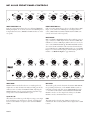
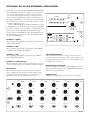
Schematics are downloadable from
dj.rane.com
1
5
1
10
0
0
+6
+6
+6
A POST B
OFF
OFF
OFF
0
BASS
MID
TREBLE
CUE
1
1
5
6
10
7
0
0
+6
+6
+6
CUE
2
BASS
MID
TREBLE
A POST B
OFF
OFF
OFF
0
2
AUX 2
AUX 1
1
5
6
10
7
0
0
+6
+6
+6
CUE
3
BASS
MID
TREBLE
A POST B
OFF
OFF
OFF
0
3
AUX 2
AUX 1
1
5
6
10
7
0
0
+6
+6
+6
CUE
4
BASS
MID
TREBLE
A POST B
OFF
OFF
OFF
0
4
AUX 2
AUX 1
1
5
6
10
7
0
0
+6
+6
+6
CUE
5
BASS
MID
TREBLE
A POST B
OFF
OFF
OFF
0
5
AUX 2
AUX 1
4
1
10
0
0
+6
+6
+6
CUE
6
BASS
MID
TREBLE
A POST B
OFF
OFF
OFF
0
6
MIX LEVEL
9
7
2
6
SIG / OL
8
5
8
9
7
10
6
ENGAGE
MIC 2
3
4
1
5
6
INPUT GAIN
2
3
AUX 5
AUX 4
AUX 3
SIG / OL
8
9
8
9
7
10
6
ENGAGE
MIC 1
INPUT GAIN
1
5
5
MIX LEVEL
4
2
3
4
2
3
AUX 5
AUX 4
AUX 3
SIG / OL
8
9
8
9
7
10
6
PHONO /
LINE
INPUT GAIN
1
5
4
MIX LEVEL
4
2
3
4
2
3
AUX 5
AUX 4
AUX 3
SIG / OL
8
9
8
9
7
10
6
PHONO /
LINE
INPUT GAIN
1
5
3
MIX LEVEL
4
2
3
4
2
3
AUX 5
AUX 4
AUX 3
SIG / OL
8
9
8
9
7
10
6
INPUT GAIN
1
5
PHONO /
LINE
MIX LEVEL
4
2
3
4
2
3
AUX 5
2
2
3
4
6
PGM
A
F 60X
10
0
8
2
10
4
2
3
8
9
6
4
4
6
8
2
8
0
10
RIGHT / PGM
LEFT / CUE
0
0
+6
+6
+6
PHONES
OFF
OFF
OFF
0
BASS
MID
B
ROTARY
MIXER
EXTERNAL
PROCESSOR
XP 2016S
MP 2016S
TREBLE
CROSSFADER
CONTOUR
POWER
POWER
SIG / OL
9
7
10
6
LEVEL
1
5
STEREO
MONO
7
0 +2 +4 +7 +10
CUE METER
STEREO
6
HOUSE
1
5
EFFECTS
LOOP
2
3
4
MONO
-20 -10 -7 -4 -2
MONITOR
CUE
8
4
8
2
6
2
8
9
6
4
MASTER
CUE
7
MASTER
XP 2016S
10
BOOTH
1
5
ROTARY MIXER
1
MIX LEVEL
9
7
2
6
8
5
SIG / OL
3
4
INPUT GAIN
10
9
2
7
8
6
3
4
AUX 5
AUX 4
AUX 2
AUX 1
AUX 4
PHONO /
LINE
AUX 3
1
AUX 3
AUX 2
AUX 1
MP 2016S XP 2016S
EXTERNAL PROCESSOR
IMPORTANT SAFETY INSTRUCTIONS
1. Read these instructions.
2. Keep these instructions.
3. Heed all warnings.
4. Follow all instructions.
5. Do not use this apparatus near water.
6. Clean only with a dry cloth.
7. Do not block any ventilation openings. Install in accordance with manufacturer’s instructions.
8. Do not install near any heat sources such as radiators, registers, stoves, or other apparatus (including amplifiers) that produce heat.
9. Do not defeat the safety purpose of the polarized or grounding-type plug. A polarized plug has two blades with one wider than the other. A
grounding-type plug has two blades and a third grounding prong. The wide blade or third prong is provided for your safety. If the provided plug
does not fit into your outlet, consult an electrician for replacement of the obsolete outlet.
10. Protect the power cord and plug from being walked on or pinched particularly at plugs, convenience receptacles, and the point where it exits from
the apparatus.
11. Only use attachments and accessories specified by Rane.
12. Use only with the cart, stand, tripod, bracket, or table specified by the manufacturer, or sold with the apparatus. When a cart is used, use caution
when moving the cart/apparatus combination to avoid injury from tip-over.
13. Unplug this apparatus during lightning storms or when unused for long periods of time.
14. Refer all servicing to qualified service personnel. Servicing is required when the apparatus has been damaged in any way, such as power supply
cord or plug is damaged, liquid has been spilled or objects have fallen into the apparatus, the apparatus has been exposed to rain or moisture, does
not operate normally, or has been dropped.
15. The plug on the power cord is the AC mains disconnect device and must remain readily operable. To completely disconnect this apparatus from
the AC mains, disconnect the power supply cord plug from the AC receptacle.
16. This apparatus shall be connected to a mains socket outlet with a protective earthing connection.
17. When permanently connected, an all-pole mains switch with a contact separation of at least 3 mm in each pole shall be incorporated in the
electrical installation of the building.
18. If rackmounting, provide adequate ventilation. Equipment may be located above or below this apparatus, but some equipment (like large power
amplifiers) may cause an unacceptable amount of hum or may generate too much heat and degrade the performance of this apparatus.
19. This apparatus may be installed in an industry standard equipment rack. Use screws through all mounting holes to provide the best support.
WARNING: To reduce the risk of fire or electric shock, do not expose this apparatus to rain or moisture. Apparatus shall not be exposed to dripping
or splashing and no objects filled with liquids, such as vases, shall be placed on the apparatus.
WARNING
The symbols shown below are internationally accepted symbols
that warn of potential hazards with electrical products.
CAUTION
RISK OF ELECTRIC SHOCK
DO NOT OPEN
ATTENTION: RISQUE DE CHOCS ELECTRIQUE - NE PAS OUVRIR
To reduce the risk of electrical shock, do not open the unit. No user
serviceable parts inside. Refer servicing to qualified service personnel.
This symbol indicates that a dangerous voltage
constituting a risk of electric shock is present
within this unit.
This symbol indicates that there are important
operating and maintenance instructions in the
literature accompanying this unit.
WARNING: This product may contain chemicals known to the State of California to cause cancer, or birth defects or other reproductive harm.
NOTE: This equipment has been tested and found to comply with the limits for a Class B digital device, pursuant to part 15 of the FCC Rules.
These limits are designed to provide reasonable protection against harmful interference in a residential installation. This equipment generates, uses
and can radiate radio frequency energy and, if not installed and used in accordance with the instructions, may cause harmful interference to radio
communications. However, there is no guarantee that interference will not occur in a particular installation. If this equipment does cause harmful
interference to radio or television reception, which can be determined by turning the equipment off and on, the user is encouraged to try to correct
the interference by one or more of the following measures:
• Reorient or relocate the receiving antenna.
• Increase the separation between the equipment and receiver.
• Connect the equipment into an outlet on a circuit different from that to which the receiver is connected.
• Consult the dealer or an experienced radio/TV technician for help.
CAUTION: Changes or modifications not expressly approved by Rane Corporation could void the user's authority to operate the equipment.
This Class B digital apparatus complies with Canadian ICES-003.
Cet appareil numérique de la classe B est conforme à la norme NMB-003 du Canada.
INSTRUCTIONS DE SÉCURITÉ
1. Lisez ces instructions.
2. Gardez précieusement ces instructions.
3. Respectez les avertissements.
4. Suivez toutes les instructions.
5. Ne pas utiliser près d’une source d’eau.
6. Ne nettoyer qu’avec un chiffon doux.
7. N’obstruer aucune évacuation d’air. Effectuez l’installation en suivant les instructions du fabricant.
8. Ne pas disposer près d’une source de chaleur, c-à-d tout appareil produisant de la chaleur sans exception.
9. Ne pas modifier le cordon d’alimentation. Un cordon polarisé possède 2 lames, l’une plus large que l’autre. Un cordon avec tresse de masse possède
2 lames plus une 3è pour la terre. La lame large ou la tresse de masse assurent votre sécurité. Si le cordon fourni ne correspond pas à votre prise,
contactez votre électricien.
10. Faites en sorte que le cordon ne soit pas piétiné, ni au niveau du fil, ni au niveau de ses broches, ni au niveau des connecteurs de vos appareils.
11. N’utilisez que des accessoires recommandés par Rane.
12. N’utilisez que les éléments de transport, stands, pieds ou tables spécifiés par le fabricant ou vendu avec l’appareil. Quand vous utlisez une valise de
transport, prenez soin de vous déplacer avec cet équipement avec prudence afin d’éviter tout risque de blessure.
13. Débranchez cet appareil pendant un orage ou si vous ne l’utilisez pas pendant un certain temps.
14. Adressez-vous à du personnel qualifié pour tout service après vente. Celui-ci est nécessaire dans n’importe quel cas où l’appareil est abimé : si le
cordon ou les fiches sont endommagés, si du liquide a été renversé ou si des objets sont tombés sur l’appareil, si celui-ci a été exposé à la pluie ou
l’humidité, s’il ne fonctionne pas correctement ou est tombé.
15. La fiche du cordon d’alimentation sert à brancher le courant alternatif AC et doit absolument rester accessible. Pour déconnecter totalement
l’appareil du secteur, débranchez le câble d’alimentation de la prise secteur.
16. Cet appareil doit être branché à une prise terre avec protection.
17. Quand il est branché de manière permanente, un disjoncteur tripolaire normalisé doit être incorporé dans l’installation électrique de l’immeuble.
18. En cas de montage en rack, laissez un espace suffisant pour la ventilation. Vous pouvez disposer d’autres appareils au-dessus ou en-dessous de celuici, mais certains (tels que de gros amplificateurs) peuvent provoquer un buzz ou générer trop de chaleur au risque d’endommager votre appareil et
dégrader ses performances.
19. Cet appareil peut-être installé dans une baie standard ou un chassis normalisé pour un montage en rack. Visser chaque trou de chaque oreille de
rack pour une meilleure fixation et sécurité.
ATTENTION: afin d’éviter tout risque de feu ou de choc électrique, gardez cet appareil éloigné de toute source d’humidité et d’éclaboussures quelles
qu’elles soient. L’appareil doit également être éloigné de tout objet possédant du liquide (boisson en bouteilles, vases,…).
ATTENTION
CAUTION
RISK OF ELECTRIC SHOCK
DO NOT OPEN
ATTENTION: RISQUE DE CHOCS ELECTRIQUE - NE PAS OUVRIR
Afin d’éviter tout risque de choc électrique, ne pas ouvrir l’appareil.
Aucune pièce ne peut être changée par l’utilisateur. Contactez un
SAV qualifié pour toute intervention.
Les symboles ci-dessous sont reconnus internationalement
comme prévenant tout risque électrique.
Ce symbole indique que cette unité utilise un
voltage élevé constituant un risque de choc
électrique.
Ce symbole indique la présence d’instructions
d’utilisation et de maintenance importantes dans le
document fourni.
REMARQUE: Cet équipement a été testé et approuvé conforme aux limites pour un appareil numérique de classe B, conformément au chapitre 15
des règles de la FCC. Ces limites sont établis pour fournir une protection raisonnable contre tout risque d’interférences et peuvent provoquer une
énergie de radiofréquence s'il n'est pas installé et utilisé conformément aux instructions, peut également provoquer des interférences aux niveaux
des équipements de communication. Cependant, il n'existe aucune garantie que de telles interférences ne se produiront pas dans une installation
particulière. Si cet équipement provoque des interférences en réception radio ou télévision, ceci peut être detecté en mettant l'équipement sous/hors
tension, l'utilisateur est encouragé à essayer de corriger cette interférence par une ou plusieurs des mesures suivantes:
• Réorienter ou déplacer l'antenne de réception.
• Augmenter la distance entre l'équipement et le récepteur.
• Connecter l'équipement à une sortie sur un circuit différent de celui sur lequel le récepteur est branché.
• Consulter un revendeur ou un technicien radio / TV expérimenté.
ATTENTION: Les changements ou modifications non expressément approuvés par Rane Corporation peuvent annuler l'autorité de l'utilisateur à
manipuler cet équipement et rendre ainsi nulles toutes les conditions de garantie.
Cet appareil numérique de classe B est conforme à la norme Canadienne ICES-003.
Cet appareil numérique de classe B est conforme à la norme Canadienne NMB-003.
OPERATORS MANUAL
MP 2016S
ROTARY DJ MIXER
1
AUX 1
2
PHONO /
LINE
AUX 2
AUX 1
3
PHONO /
LINE
AUX 2
AUX 1
4
PHONO /
LINE
AUX 2
AUX 1
5
PHONO /
LINE
AUX 2
AUX 1
AUX 3
AUX 3
AUX 3
AUX 3
AUX 4
AUX 4
AUX 4
AUX 4
AUX 4
AUX 5
5
4
6
7
3
4
8
2
6
7
3
9
1
AUX 5
5
4
8
2
SIG / OL
10
INPUT GAIN
6
7
3
9
1
AUX 5
5
2
SIG / OL
4
8
10
1
INPUT GAIN
6
10
1
INPUT GAIN
6
2
SIG / OL
10
1
INPUT GAIN
6
10
1
INPUT GAIN
OFF
SIG / OL
9
1
5
5
6
7
4
2
1
10
5
7
CUE
1
1
10
5
7
3
9
MIX LEVEL
6
4
8
2
9
MIX LEVEL
6
4
3
8
2
CUE
2
1
10
5
7
3
9
MIX LEVEL
6
4
8
EFFECTS
LOOP
OFF
MONO
SIG / OL
2
CUE
3
9
1
10
MIX LEVEL
5
MASTER
CUE
4
1
10
CUE
5
4
1
10
2
4
CUE
6
8
CUE
MONO
MP 2016S
STEREO
6
+6
ROTARY
MIXER
7
8
3
2
9
1
PGM
MONITOR
5
4
6
8
9
MIX LEVEL
2
BASS
STEREO
6
8
2
9
MIX LEVEL
7
3
8
2
6
4
7
3
+6
0
10
INPUT GAIN
6
4
8
MID
10
OFF
3
+6
0
HOUSE
XP 2016S
CUE
9
8
2
10
8
2
SIG / OL
7
3
BOOTH
7
3
9
8
9
TREBLE
6
4
3
1
5
4
8
5
7
2
7
3
9
ENGAGE
AUX 5
5
4
8
2
SIG / OL
AUX 3
AUX 4
7
3
9
ENGAGE
0
6
4
AUX 2
AUX 5
5
MASTER
5
MIC 2
AUX 1
AUX 2
AUX 3
AUX 5
6
MIC 1
10
POWER
LEVEL
PHONES
QUICK START
The MP 2016S has Split Cue! If you don’t know what that is, we
suggest you take the time to read this entire manual so you learn
lots of other things to get the best sound and features out of your
new mixer. But if you know what Split Cue is, at least read this
section to refresh your knowledge of the rest of the MP 2016S.
There are four dedicated phono preamplifiers. One each for
Input channels 1-4. Switches on the rear panel set each preamplifier for LINE or PHONO operation. Make sure you have these
switches set correctly for your application.
There are two dedicated MIC preamplifiers, one each for
Input channels 5-6. Rear panel switches set each preamplifier for
LINE or MIC operation. Make sure you have these switches set
correctly. MIC GAIN controls adjust each preamplifier for the
correct sensitivity. With a MIC selected and ENGAGED, set the
front INPUT GAIN control to “10” and adjust the rear MIC
GAIN to just keep the Input Channel SIG / OL indicator green,
not red. Set the rear panel tone controls as desired. The MIC
ENGAGE switch ducks the BOOTH Output by 12 dB unless
defeated with internal jumpers.
Before installing this mixer permanently, be sure to read the
MIC / LINE INPUTS section on page Manual-6.
All five stereo line-level AUX Inputs are available for each of
the six Input Channels.
Adjust the INPUT GAIN controls so they blink the green
SIG / OL indicators. If an indicator is red, the INPUT GAIN
control is set too high. This provides optimum signal to noise,
dynamic range and MIX LEVEL control consistency.
The BOOTH may select CUE or MASTER as its source.
CUE allows monitoring Inputs in the booth without headphones.
The XP 2016S switch engages the optional XP 2016S processor. If the XP 2016S is not connected, the switch has no effect.
The EFFECTS LOOP switch switches the Loop in (up) or
out (down). If nothing is connected to the EFFECTS LOOP
RETURN, the switch has no effect.
The MASTER MONO / STEREO switch influences both
BOOTH and HOUSE OUTPUTS. It does not affect the EFFECTS LOOP or TAPE OUTPUTS.
Two TAPE OUTPUTS are provided. One is a PRE-EFFECTS Loop and one is a POST-EFFECTS Loop. The POSTEFFECTS Loop Tape Output has a LEVEL control and may be
used as a pre-tone control AUX Output.
The MP 2016S Master Output uses Accelerated Slope ™ tone
controls that provide full “kill” for TREBLE, MID and BASS.
The MASTER SIG / OL indicator monitors the master mix
before and after the tone controls. This indicator should light
green most of the time. It is OK for it to flash red on occasion.
This provides optimum signal-to-noise and dynamic range.
HOUSE and BOOTH are the only level controls that do not
affect the MASTER SIG / OL indicator.
The HOUSE OUTPUT has both balanced (XLR) and
unbalanced (RCA) Outputs. To avoid hum, always use the balanced (XLR) Outputs for longer cable runs (typically greater
than 10 feet, or 3 meters).
Headphone cueing allows monitoring MASTER or CUE
sources. If MIX LEVEL controls are operated at less than “7”, be
sure to turn the PHONES LEVEL down before selecting a CUE
as it may be much louder than the Master Mix. The Headphone
Output is low-impedance high-current, so do not short the tip
and ring together or to ground.
WEAR PART
The MP 2016S contains no wear parts. The XP 2016S contains the following wear part subject to the ninety (90) day warranty period
described on page Service-1: (1) Active Crossover Assembly F 60X.
Manual-1
MP 2016S FRONT PANEL CONTROLS
1
2
PHONO /
LINE
AUX 1
AUX 2
AUX 1
3
PHONO /
LINE
AUX 2
AUX 1
4
PHONO /
LINE
AUX 2
PHONO /
LINE
AUX 2
AUX 1
AUX 3
AUX 3
AUX 3
AUX 3
AUX 4
AUX 4
AUX 4
AUX 4
AUX 4
AUX 5
5
4
6
7
2
5
4
8
3
AUX 5
6
8
3
9
2
AUX 5
5
4
7
6
8
3
9
2
3
8
2
3
9
1
8
2
10
10
1
AUX 1
2
PHONO /
LINE
AUX 2
AUX 1
PHONO /
LINE
AUX 2
ENGAGE
8
8
3
8
AUX 2
AUX 2
AUX 2
AUX 3
AUX 3
AUX 4
AUX 4
AUX 5
3
9
1
5
6
5
3
8
1
2
9
10
MIX LEVEL
6
5
7
2
CUE
1
10
MIX LEVEL
8
2
CUE
9
SIG / OL
3
MASTER
5
8
10
6
MIX LEVEL
INPUT GAIN
INPUT GAIN controls allow the user to match input levels.
Adjust these to make the SIG / OL indicator flash green. If the
indicators turn red, reduce the INPUT GAIN. Adjusting the
INPUT LEVEL controls correctly maximizes dynamic range
and provides consistent MIX LEVEL response.
Input SIG / OL
These dual-color indicators provide help in setting correct input
levels. A flashing green indication is optimal. A red light that
lasts more than a flash is a request to turn down the INPUT
GAIN.
5
2
CUE
3
MIX LEVEL
5
5
7
10
CUE
MASTER
MIX LEVEL
6
7
3
4
10
MIX LEVEL
2
8
9
1
2
6
8
2
CUE
5
10
SIG / OL
10
4
9
1
3
8
6
8
6
4
BOOTH
9
1
2
CUE
4
MONITO
INPUT GAIN
3
9
10
CUE
7
2
SIG / OL
10
4
6
3
8
6
8
8
1
5
4
7
9
1
7
1
6
2
2
INPUT GAIN
3
9
1
5
2
SIG / OL
10
4
ENGAGE
AUX 5
3
8
6
7
AUX 3
2
4
8
AUX 4
4
10
BOOTH
7
3
SIG / OL
ENGAGE
7
9
1
2
CUE
2
6
AUX 2
INPUT GAIN
3
9
1
6
2
SIG / OL
10
4
8
5
3
9
INPUT GAIN
3
8
9
AUX 5
4
7
8
10
4
6
2
SIG / OL
INPUT GAIN
7
1
9
1
5
3
8
10
AUX 5
4
7
2
SIG / OL
INPUT GAIN
4
6
3
8
2
AUX 5
5
1
5
4
8
AUX 4
4
3
2
7
3
AUX 3
7
ENGAGE
INPUT SELECTORS
5-6
1
10
1
10
1
10
Each six-position
chooses
a dedicated
mono
INPUT GAINInput Selector
INPUT
GAIN
INPUT
GAIN MIC
Input, or one of five stereo AUX Inputs as its Input Channel
source. (MIC GAIN trim, MIC / LINE switch and MIC tone
5
6
5
6
5
6
controls 4are located
7
7 on the rear
4
4 panel).7
AUX 4
6
6
2
AUX 3
5
5
3
SIG / OL
AUX 4
4
AUX 3
6
4
AUX 5
4
9
5
MIC 2
AUX 4
7
AUX 3
AUX 5
AUX 1
AUX 2
MIC ENGAGE
2
9
2
9
2
9
2
9
MIC 1 and
a10mic on
1
1
10
1 MIC
102 ENGAGE 1switches
10 allow switching
CUE
CUE
CUE
CUE
(down).
Input
and
MIC EN-6
MIX LEVEL (up)
3 or off
MIX
LEVEL A MIC
4
MIXmust
LEVELbe selected
5
MIX LEVEL
GAGE on to activate a MIC Input. When a mic is not in use, be
sure to switch MIC ENGAGE off. The MIC ENGAGE switches
also activate the Booth Ducker. This attenuates the Booth Output -12 dB whenever a MIC ENGAGE switch is on, even if MIC
3
4
5
6
Input is not selected (internal jumpers allow disabling the Booth
MIC 2
AUX 1
PHONO /
AUX 1
PHONO /
AUX 1
MIC 1
AUX 1
Ducker—see
Mic/Line
Inputs
on page
Manual-6).
LINE
LINE
CUE
2
MIX LEVEL
6
2
SIG / OL
3
9
1
CUE
1
MIX LEVEL
SIG / OL
5
3
9
INPUT SELECTORS
1-4
1
10
1
10
1
10
Each six-positionINPUT
Input
Selector chooses
a GAIN
dedicated PHONO
/
GAIN
INPUT
INPUT GAIN
LINE preamplifier, or one of five stereo line-level AUX Inputs as
its Input Channel source. (PHONO / LINE switches are on the
5
6
5
6
5
6
rear panel).
7
7
7
4
4
4
SIG / OL
MIC 1
AUX 5
4
7
6
AUX 2
AUX 3
AUX 5
Manual-2
AUX 1
5
CUE
6
MIX LEVEL
These studio-grade controls determine the Master MIX LEVEL.
For optimum performance, set the INPUT GAIN controls as
indicated previously, and then operate MIX LEVELS between
“7” and “10” for full volume. Use the HOUSE and BOOTH
LEVEL controls to set the output levels. Always set the MIX
LEVEL controls to minimum when not in use.
CUE
The CUE signal is selected using CUE 1-6 switches in any
combination. The associated yellow indicator lights when a CUE
is active.
CUE
MONITO
MASTER HOUSE Level
This studio-grade control sets the HOUSE Output level.
6
MASTER
5
MIC 2
6
5
7
4
ENGAGE
8
8
OFF
SIG / OL
9
1
0
OFF
MONO
MASTER
GAIN
6
7
4
EVEL
2
2
4
6
8
CUE
MONO
MP 2016S
STEREO
6
+6
ROTARY
MIXER
7
8
3
2
9
1
PGM
MONITOR
5
4
6
8
CUE
6
BASS
STEREO
OFF
9
+6
0
10
10
MID
HOUSE
SIG / OL
8
+6
10
EFFECTS
XP 2016S LOOP
CUE
9
8
2
10
BOOTH
7
7
3
9
1
MASTER MONO / STEREO switch
This sets the MASTER mix signal to MONO or STEREO operation. It effects both BOOTH and HOUSE Outputs.
TREBLE
6
4
3
2
6
0
10
POWER
LEVEL
PHONES
HEADPHONE MONITOR
MONITOR determines the source of the PHONES signal. With
the MONITOR MONO switch out, the control pans between
stereo CUE and stereo PGM signals. The PGM signal follows
the HOUSE Output (same signal going to the Master House).
With MONITOR MONO selected (in), the MONITOR
control pans between mono CUE (left ear) and mono PGM
(right ear).
The Phones LEVEL control determines the headphone output level. If you are mixing with the MIX LEVEL controls below
“7”, be sure to turn the Phones LEVEL down before selecting a
CUE source as it may be much louder than the Master Mix.
The PHONES output is very low impedance and high
current so do not short tip and ring together or tie to ground, as
is common with many low- cost mono cups. Use resistors of
300 to 600 Ω in series with each output for mono applications,
although this significantly reduces output power.
BOOTH
T = LEFT CUE / MASTER switch and Level
R = RIGHT
S = GROUND
TO MONO PHONE
MASTER SIG / OL indicator
This dual color indicator helps set correct MASTER mix levels.
A flashing or steady green indication is optimal. The red indicator may flash only briefly on rare occasion...regular flashing or
steady-on means that distortion is imminent and Levels need
reducing.
XP 2016S switch
This engages the optional XP 2016S External Processor. If the
XP 2016S is not connected, the switch does nothing. If an XP
2016S is connected and the switch is on (up), it routes the MIX
LEVEL Outputs to the XP 2016S and returns a stereo MASTER
signal to the MP 2016S.
EFFECTS LOOP switch
This engages the EFFECTS LOOP when up. If nothing is connected to the EFFECTS LOOP RETURN, the switch has no
effect.
TREBLE tone control
Allows adjusting the amplitude of frequencies above 4 kHz from
+6 dB to OFF (full kill).
MID tone control
Allows adjusting the amplitude of frequencies between 300 Hz
and 4 kHz from +6 dB to OFF (full kill).
BASS tone control
Allows adjusting the amplitude of frequencies below
300 Hz from +6 dB to OFF (full kill).
POWER indicator
This yellow indicator lights whenever AC power is connected to
the unit.
AUDIO PRECISION
10
Low 0, Mid 0, High 0
5
The BOOTH CUE / MASTER switch selects MASTER
mix or CUE selection as the Booth source. This allows CUE
monitoring in the Booth without headphones. The BOOTH
Level controls the volume to the Booth Output.
AMPL(dBr) vs FREQ(Hz)
Summed Response
0
Low
-5
Mid
-10
Low 0,
Mid Off,
High Off
-15
-20
High
Low Off,
Mid 0,
High Off Low Off,
Mid Off,
High 0
-25
-30
-35
-40
20
100
1k
10k
50k
Treble, Mid and Bass control bands and the flat summed response
Manual-3
REAR PANEL INPUTS & OUTPUTS
MIC 2
MP 2016S
BASS
TREBLE
MADE IN U.S.A.
RANE CORP.
U.S. PATENT 7,043,032
0
0
-12
ACN 001 345 482
+12
-12
GAIN
+12
MIC 1
100-240 V
50/60 Hz 12 WATTS
0
-12
HOUSE
OUTPUTS
+12
-12
GAIN
MIC
LINE
3
BOOTH
OUTPUTS
2
1
L
L
L
R
R
R
R
+12
EFFECTS LOOP
RETURN
INPUTS
L
LINE
PHONO
This device complies with Part 15 of the FCC Rules. Operation is
subject to the following two conditions: (1) this device may not cause
harmful interference, and (2) this device must accept any interference
received, including interference that may cause undesired operation.
PIN 2 = POSITIVE
PIN 3 = NEGATIVE
PIN 1 = CHASSIS GROUND
R
TREBLE
0
MIC
LINE
XLR WIRING
COMMERCIAL AUDIO
EQUIPMENT 24TJ
BASS
4
SEND
MIC 1 and MIC 2 XLR
jacksLEFT
RIGHT
L
The MIC 1 Input
provides
a dedicated balanced
preamplifier
LEFT
L
LEVEL
for Input Channel 5, while MIC 2 provides the preamplifier for
R mode.
RIGHT 6. Each may operate in MIC
R
Input Channels
or LINE
Each of these preamplifiers features GAIN trim with BASS and
TREBLE tone controls.
MIC / LINE switches
These select MIC or LINE mode for the MIC Inputs. In MIC
mode, the gain range is 20 to 50 dB. In LINE mode, the gain
range is 0 to 30 dB. In addition to setting the proper gain range
for MIC or LINE level Inputs, these switches also select the
proper Input impedance.
TAPE
OUTPUTS
— PHONO GROUND —
XP 2016S
EXTERNAL
PROCESSOR
AUX INPUTS
INPUTS 1-4 RCA jacks
5
4
3
2
1
INPUTS
1-4
provide
dedicated
preamplifiers
for
Input
Channels
L
L
L
L
L
L
1-4 respectively. Each may operate in RIAA PHONO or LINE
R
R
R
R
R
mode.R
POST
PRE
EFFECTS EFFECTS
PHONO / LINE switches
These switches set Input Channel preamplifiers 1-4 for PHONO
or LINE mode. Make certain these switches are set correctly for
your source.
PHONO GROUND
These lugs are provided to connect ground wires from turntables.
When using a turntable, proper grounding is essential.
MIC GAIN trim
These controls adjust the preamplifier for optimum dynamic
range. Each has a range of 30 dB, allowing a wide range of
sources to be used. To properly set this control, set the associated
front panel INPUT GAIN to “10”, turn the MIC ENGAGE
switch on and adjust the MIC GAIN so that the input SIG / OL
indicator flashes red only during very loud peaks. The front panel
INPUT GAIN control can then be adjusted as required according to the instruction outlined above under INPUT GAIN
control.
MIC TREBLE and BASS controls
Separate TREBLE and BASS tone controls are provided for each
MIC preamplifier. These allow adjustment of the tonal response
of each Mic or Line source at the MIC Inputs. If you add a
significant amount of boost, you may need to readjust the rear
panel GAIN trims as outlined before.
Manual-4
IMPORTANT NOTE: CHASSIS GROUNDING
If after hooking up your system it exhibits excessive hum or
buzzing, there is an incompatibility in the grounding configuration between units somewhere.
If your equipment is in a rack, verify that all chassis are tied
to a good earth ground, either through the line cord grounding
pin or the rack screws to another grounded chassis.
Please refer to the RaneNote “Sound System Interconnection”
supplied with this manual and available from our website for
further information on system grounding.
MADE IN U.S.A.
RANE CORP.
U.S. PATENT 7,043,032
-12
ACN 001 345 482
GAIN
0
0
+12
-12
0
MIC
LINE
+12
-12
XLR WIRING
HOUSE
OUTPUTS
R
RIGHT
100-240 V
50/60 Hz 12 WATTS
+12
-12
MIC
LINE
L
L
L
R
R
R
BOOTH
OUTPUTS
LEFT
EFFECTS LOOP
RETURN
TAPE
OUTPUTS
SEND
POST
PRE
EFFECTS EFFECTS
L
LEFT
L
RIGHT
R
L
R
+12
LINE
PHONO
This device complies with Part 15 of the FCC Rules. Operation is
subject to the following two conditions: (1) this device may not cause
harmful interference, and (2) this device must accept any interference
received, including interference that may cause undesired operation.
PIN 2 = POSITIVE
PIN 3 = NEGATIVE
PIN 1 = CHASSIS GROUND
COMMERCIAL AUDIO
EQUIPMENT 24TJ
GAIN
0
LEVEL
R
EFFECTS LOOP SEND ¼" jacks
SEND Outputs are unbalanced standard ¼" tip-sleeve jacks.
They provide a line level Output for external signal processing or
effects units. If effects are not being used, these outputs may be
used as Auxiliary Outputs.
EFFECTS LOOP RETURN ¼" jacks
RETURN Inputs are unbalanced standard ¼" tip-sleeve jacks.
They provide the Input from external signal processing or effects
units. Switching jacks are used so there is no loss of signal if the
front panel EFFECTS LOOP switch is active with no effects
connected. RETURN Inputs are not appropriate for Auxiliary
Inputs as this signal is only selected when the front panel EFFECTS LOOP switch is active, at which time Master signal is
derived only by the signal present at the RETURN Inputs, the
mix signals are disconnected.
BOOTH OUTPUT RCA jacks
The unbalanced stereo BOOTH OUTPUT is normally used for
booth monitoring. As previously outlined, very flexible source
selection is provided as well as MIC ducking. Remember, the
BOOTH OUTPUT is attenuated by 12 dB whenever one of the
front panel MIC ENGAGE switches is active (unless ducking
has been defeated with the internal jumper. See Mic/Line Inputs
on page Manual-6).
HOUSE OUTPUT jacks
Both balanced (XLR) and unbalanced (RCA) jacks are provided.
For long runs, we highly recommend using the balanced XLR
outputs. The unbalanced RCA outputs are intended for short
runs of less than 10 feet (3 meters). Both may be used simultaneously if required.
— PHONO GROUND —
AUX INPUTS
XP 2016S
EXTERNAL
PROCESSOR
5
4
3
2
1
L
L
L
L
L
L
R
R
R
R
R
R
AUX INPUTS 1-5 RCA jacks
These five stereo AUX Inputs are unbalanced, line level Inputs
available for selection on all six Input channels.
XP 2016S EXTERNAL PROCESSOR
The XP 2016S port provides the required socket for connecting
the ribbon cable (supplied with the optional XP 2016S). If an XP
2016S is not connected, the front panel XP 2016S engage switch
has no effect. If ribbons longer than that supplied with the XP
2016S are used, crosstalk may increase and immunity to RF,
magnetic and conducted interference may be compromised —
don’t do it.
TAPE OUTPUT – PRE-EFFECTS RCA jacks
This unbalanced line-level Output is located before the EFFECTS LOOP and tone controls for recording the Master Mix.
MIC Inputs are mixed as any other source and will be present at
both TAPE OUTPUTS.
TAPE OUTPUT – POST-EFFECTS RCA jacks
This unbalanced line-level Output is located after the EFFECTS
LOOP and before the tone controls. This may be used as an
Auxiliary Output. For this application, as well as for more flexibility when recording, a LEVEL control has been provided as
described below.
MIC 2
MP 2016S
BASS
BASS
TREBLE
TREBLE
TAPE OUTPUT – POST-EFFECTS
GAIN LEVEL control
0
0
0
0
MIC
LINE
This adjusts the POST-EFFECTS TAPE OUTPUT
from unity
gain to off, allowing
optimum
-12 +12 -12 +12
-12 +12
-12 +12 sensitivity adjustment for recording or for an Auxiliary Output.
MADE IN U.S.A.
RANE CORP.
U.S. PATENT 7,043,032
ACN 001 345 482
XLR WIRING
This device complies with Part 15
subject to the following two condition
harmful interference, and (2) this dev
received, including interference that m
PIN 2 = POSITIVE
PIN 3 = NEGATIVE
PIN 1 = CHASSIS GROUND
COMMERCIAL AUDIO
EQUIPMENT 24TJ
R
100-240 V
50/60 Hz 12 WATTS
GAIN
IEC320-C5
power jack BOOTH EFFECTS LOOP
HOUSE
OUTPUTS
SEND
Connects
with the properOUTPUTS
power cableRETURN
to
RIGHT
LEFT
AC line voltage anywhere in the world,
L
LEFT
L
100-240
VAC.
RIGHT
R
R
Manual-5
L
OPERATION
RIAA PHONO/LINE INPUTS
Input channels 1 through 4 each have a dedicated preamplifier.
A rear panel switch allows setting these preamps for PHONO
or LINE level signals. Make sure you have the switch in the correct
position for your application. The source selectors for Input channels 1 - 4 may select the dedicated PHONO / LINE preamplifier
or one of the five stereo AUX Inputs as the source.
With normal program material playing, set the INPUT
GAIN control to a level that causes the SIG / OL indicator to
flash green. The SIG / OL indicator should not flash red. This
will ensure optimum signal to noise ratio and dynamic range. If
INPUT GAIN controls are set too high, you may not have the
required headroom for mixing multiple Inputs. If your levels are
set too low, signal-to-noise ratio is compromised.
In addition to optimizing noise and dynamic range, properly setting INPUT GAIN allows the MIX LEVEL control to
operate predictably over its entire range. The taper of the MIX
LEVEL control is non-linear and will have different attenuation
verses rotation characteristics depending on its position. As can
be seen in the figure below, if you are mixing between 30% and
60% of rotation, MIX LEVEL will behave much differently than
if operated between 65% and 95% of rotation.
10
20
30
40
50
60
70
80
90
100
90
80
70
60
50
40
30
20
10
0
100
Attenuation
Mix Level Taper
Rotation
MIC / LINE INPUTS
Input channels 5 and 6 each have dedicated preamplifiers. A rear
panel switch allows setting these Inputs for MIC or LINE level
signals. Make sure you have the switch in the correct position for
your application. While these Inputs are designed for use with
dynamic microphones (no phantom power) or wireless microphones with line level output, they will accept just about any
mono signal. While balanced operation is highly recommended,
these Inputs may be operated unbalanced with short cables to
the source (less than 10 feet or 3 meters). The source selectors for
Input channels 5 and 6 may select the dedicated MIC / LINE
preamplifier or one of the five stereo AUX inputs.
Prior to permanent installation, adjust the preamplifier
GAIN, BASS and TREBLE controls (located on the rear panel)
for the intended source.
In addition to the MIC / LINE switch, each preamplifier has
a rear panel MIC GAIN trim. To properly set the MIC GAIN,
set the front panel INPUT GAIN control to “10.” This allows
Manual-6
the INPUT GAIN SIG / OL indicator to accurately indicate the
signal level. Adjust the MIC GAIN so the red OL indicator just
stays off during the highest signal peaks (if a microphone is in
use, yell into it). The MIC GAIN control should only have to be
set once for the source in use. Use the front panel INPUT GAIN
control for trimming the gain after installation.
Next adjust the rear panel MIC 1 and MIC 2 BASS and
TREBLE controls for the desired tonal quality. If you add a lot
of BASS or TREBLE boost, you may want to readjust the MIC
GAIN control to avoid possible overloading.
MIC 1 and MIC 2 each have an ENGAGE switch to the
right of the Input Selector. For a mic signal to be active, the
selector must be set to MIC and the MIC ENGAGE switch set
to ENGAGE (up).
When either of the switches is set to the ENGAGE position, the BOOTH OUTPUT is ducked (attenuated) by 12 dB
(about ¼th ) to reduce potential feedback. If you do not want the
BOOTH OUTPUT to duck when a MIC source is engaged,
you can remove the top cover and set the internal jumper accordingly. There is an independent Ducker select jumper for MIC 1
and MIC 2.
It sounds like a lot of trouble to set the input stages up correctly, however, you will be amazed at how much better your
performance sounds.
MIX LEVEL
With the Input stages properly adjusted, you are free to use the
MIX LEVEL control for mixing. For most applications, channels
will be mixed at about 70% to 100% rotation. BOOTH and
HOUSE level controls then set the output volume. The MASTER SIG / OL indicator displays the signal level of the mix. The
Green SIG indicator should flash or remain on. The Red OL
indicator should remain off (it may flash occasionally, but if it is
on every beat it is too hot). To correct an overload condition, one
or more of the MIX LEVEL controls must be turned down. The
MASTER SIG / OL indicator monitors the signal before and
after the tone control, so if you use a lot of boost, remember to
monitor this indicator.
TONE CONTROLS
The MP 2016S uses high-performance tone control circuits
that isolate the signal into three bands. The level of each band
is independently controlled, and then recombined. This topology provides full “kill” for TREBLE, MID and BASS. If all
three bands are set to the same level, there will be no change in
frequency response, only amplitude. It is the difference in settings
that determines the tonal quality of the signal. These advanced
tone controls provide excellent dynamic response with fixed
phase shift. Control is smooth and predictable. The tone controls
can isolate beats, vocals and “high-hat,” as well as adjust general
tonal quality. Remember that the dedicated Mic tone controls
(on the rear panel) are used to equalize the Microphone Inputs.
OPTIONAL XP 2016S EXTERNAL PROCESSOR
3
0
OFF
0
OFF
0
OFF
Combining the optional XP 2016S EXTERNAL PROCESSOR
with the MP 2016S adds three-band, full-cut, Accelerated-Slope™
tone controls and
Assign switches6for
4 A-POST-B Crossfader
5
TREBLEof the six Input
TREBLE
TREBLE
TREBLE
0
0
0
each
channels. You also
get
a high-performance
Active-Crossfader™ with full-range Contour control and a stereo
10-segment peak dBu Master / Cue Meter with peak hold. With
+6
OFF
+6
OFF
+6
OFF
+6
these added features, the system accommodates the diverse needs
MID
MID
MID
MID
0
0
0
of virtually all DJ mixing styles.
The post MIX LEVEL signals from the MP 2016S are routed
to
the
XP 2016S,
processed
by theOFFtone+6controls, thenOFF
assigned
to
+6
OFF
+6
+6
the
A
side
of
the
fader,
B
side
of
the
fader
or
post
fader.
The
mixed
BASS
BASS
BASS
BASS
0
0
0
signal is returned to the MP 2016S. If the XP 2016S engage
switch is active, the MASTER signal gets the XP 2016S mix. If
engage
+6 the XP 2016S
OFF
+6 switch is not
OFFactive,
+6 the MASTER
OFF signal
+6
just gets the MP 2016S mix.
A POST B
A POST B
A POST B
POWER
CUE METER
LEFT / CUE
-20 -10 -7 -4 -2
0 +2 +4 +7 +10
RIGHT / PGM
CROSSFADER
CONTOUR
XP 2016S
0
2
4
6
8
10
10
8
6
4
2
0
EXTERNAL
PROCESSOR
B
F 60X
A POST B
CHANNEL 1-6 TREBLE
Allows adjusting the amplitude of frequencies above 4 kHz from
+6 dB to OFF (full kill).
A
CHANNEL 1-6 MID
Allows adjusting the amplitude of frequencies between 300 Hz
and 4 kHz from +6 dB to OFF (full kill).
CHANNEL 1-6 BASS
Allows adjusting the amplitude of frequencies below 300 Hz
from +6 dB to OFF (full kill).
CROSSFADER CONTOUR
This control allows adjusting the “shape” of the Crossfader response from a gentle curve for smooth long running fades, to the
steep pitch required for performance cut and scratch effects. (See
the graph in the Data Sheet.)
CHANNEL 1-6 A/POST/B Assign
These switches assign each of the six input channels to the A side
of the Crossfader, B side of the Crossfader or POST Crossfader.
PEAK PROGRAM / CUE METER
The stereo 10-segment Cue Meter on the XP 2016S monitors the
same signal as the headphones. See the HEADPHONE MONITOR section on page Manual-3.
CROSSFADER
This implements using Ranes’ proprietary Active Crossfader™
design. All audio is isolated from the control element, greatly
extending the life and performance of the control. See page
Manual-8 for cleaning and replacement instructions.
1
2
TREBLE
0
OFF
+6
MID
0
OFF
+6
OFF
+6
+6
OFF
OFF
OFF
+6
+6
OFF
+6
OFF
OFF
+6
+6
OFF
+6
OFF
OFF
+6
+6
OFF
+6
OFF
OFF
+6
OFF
+6
MID
+6
BASS
0
OFF
-20 -10
+6
0
BASS
0
TREBLE
0
MID
0
BASS
0
6
TREBLE
0
MID
0
BASS
0
5
TREBLE
0
MID
0
BASS
0
4
TREBLE
0
MID
0
BASS
0
3
TREBLE
0
OFF
POWER indicator
This yellow indicator lights whenever AC power is connected.
+6
F 60X
A POST B
A POST B
A POST B
A POST B
A POST B
A POST B
A
Manual-7
Power
This IEC320-C5 power jack receives the power cable shipped
with the unit.
MP 2016S Mixer Port
This is the required socket to connect the XP 2016S to the MP
2016S, using the ribbon cable supplied with the XP 2016S. If
a ribbon longer that that supplied with the XP 2016S is used,
crosstalk may increase, and immunity to RF, magnetic and conducted interference may be compromised.
XP 2016S Ribbon Connections: (PIN 1 marked Ñ)
1)GND
2)GND
3) MIX RIGHT OUT
4) MIX LEFT OUT
5)GND
6) METER LEFT IN
7) METER RIGHT IN
8)GND
9) CH 6R IN
10) CH 6L IN
11)GND
12) CH 5R IN
13) CH 5L IN
14)GND
15) CH 4R IN
16) CH 4L IN
17)GND
18) CH 3R IN
19) CH 3L IN
20)GND
21) CH 2R IN
22) CH 2L IN
23) XP 2016 ENABLE (GND)
24) CH 1R IN
25) CH 1L IN
26)GND
Fader Cleaning
With heavy use in harsh environments, the faders may need
lubrication. This treatment extends longevity and can make used
faders as good as new. The fader assembly must be removed from
the XP 2016S for proper cleaning. We recommend:
Caig DeoxIT® Fader F-series spray lubricant
Order it from:
CAIG Laboratories, Inc.
12200 Thatcher Ct.
Poway, CA 92064
Phone 800-CAIG-123
Email [email protected]
Web www.caig.com
CLEANING INSTRUCTIONS
A. Fader assembly removal
1. Remove (2) 3mm screws.
2. Draw fader assembly out through hole.
3. Remove ribbon cable.
B. Fader cleaning
1. Hold the fader assembly away from the mixer.
2. Position the fader at mid-travel.
3. Spray cleaner/lubricant into both ends of the fader.
4. Move the fader over its full travel back and forth a few times.
5. Shake excess fluid from the fader assembly.
6. Wipe off excess fluid.
At this point the control should be operational. If fader performance is questionable then replacement of the pot is the only
sure remedy. The fader is available to purchase online in the Rane
Factory Store at rane.com. You may also call the Rane factory
if you are in the USA, or call your distributor outside the USA
(rane.com/internat.html).
XP 2016S
MADE IN U.S.A.
RANE CORP.
U.S. PATENT 7,043,032
ACN 001 345 482
This device complies with Part 15 of the FCC Rules. Operation is
subject to the following two conditions: (1) this device may not cause
harmful interference, and (2) this device must accept any interference
received, including interference that may cause undesired operation.
COMMERCIAL AUDIO
EQUIPMENT 24TJ
R
100-240 V
50/60 Hz 12 WATTS
MP 2016S
MIXER
©Rane Corporation 10802 47th Ave. W., Mukilteo WA 98275-5000 TEL 425-355-6000 FAX 425-347-7757 WEB rane.com
Manual-8
DOC 111041