1
RATOR'S MANUAL
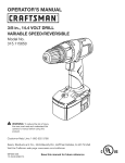
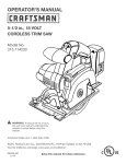
1/2 in., 19,2 VOLT CORDLESS DRILL-DRIVER
VARIABLE SPEED/REVERSIBLE
Model No.
315.115440
,_
BATTERIES AND CHARGERS
SOLD SEPARATELY
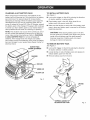
WARNaNG" To reduce the risk of injury,
the user must read and understand the
operator's manual before using this
product.
Customer
Help Line: 1-800-932-3188
Sears, Roebuck and Co., 3333 Beverly Rd., Hoffman
Visit the Craftsman web page: www.sears.com/craftsman
983000-852
4-21-06 (REV:01)
Save this manual
Estates, IL 60179 USA
for future
US
reference
[] Warranty............................................................................................................................................................
2
[] Introduction
........................................................................................................................................................
2
[]
[]
[]
[]
[]
GeneralSafetyRules............................................................................................................................................
3-4
SpecificSafetyRules............................................................................................................................................
5
SafetyRulesforCharger......................................................................................................................................
6
Symbols
.............................................................................................................................................................
7-8
Features............................................................................................................................................................
9-10
[]
[]
[]
[]
Assembly
...........................................................................................................................................................
10
Operation
...........................................................................................................................................................
11-17
Adjustments
.......................................................................................................................................................
18
Maintenance
.......................................................................................................................................................
19-20
[] ExplodedViewandPartsList.................................................................................................................................
21
[] PartsOrdering/ Service ....................................................................................................................................
Back Page
ONE-YEAR FULL WARRANTY
ON CRAFTSMAN
TOOL
If this Craftsman tool fails to give complete satisfaction within one year from date of purchase, RETURN IT TO ANY
SEARS STORE OR OTHER CRAFTSMAN OUTLET IN THE UNITED STATES FOR FREE REPLACEMENT.
If this Craftsman tool is used for commercial
purchase.
or rental purposes, this warranty applies for only 90 days from the date of
This warranty gives you specific legal rights, and you may also have other rights which vary from state to state.
Sears, Roebuck
and Co., Hoffman
Estates, IL 60179
This tool has many features for making its use more pleasant and enjoyable. Safety, performance, and dependability
been given top priority in the design of this product making it easy to maintain and operate.
_1_ WARNING:
Some dust created by power sanding, sawing, grinding, drilling, and other construction
have
activities
contains chemicals known to cause cancer, birth defects or other reproductive harm. Some examples of these
chemicals are:
• lead from lead-based paints,
crystalline silica from bricks and cement and other masonry products, and
arsenic and chromium from chemically-treated lumber.
Your risk from these exposures varies, depending on how often you do this type of work. To reduce your exposure
to these chemicals: work in a well ventilated area, and work with approved safety equipment, such as those dust
masks that are specially designed to filter out microscopic particles.
,_
WARNING!
Read all instructions. Failure to follow
all instructions listed below may
shock, fire and/or serious injury.
tool" in all of the warnings listed
mains-operated (corded) power
ated (cordless) power tool.
SAVE THESE
WORK
result in electric
The term "power
below refers to your
tool or battery-oper-
INSTRUCTIONS
AREA SAFETY
[] Keep work area clean and wei[ lit. Cluttered or dark
areas invite accidents.
[] Do not operate power tools in explosive atmo=
spheres, such as in the presence of flammable
liquids, gases or dust. Power tools create sparks
which may ignite the dust or fumes.
[] Keep children and bystanders away while operating a power tool. Distractions can cause you to lose
control.
ELECTRICAL
SAFETY
[] Power too[ plugs must match the outlet. Never
modify the plug in any way. Do not use any adapter
plugs with earthed {grounded) power tools.
Unmodified plugs and matching outlets will reduce
risk of electric shock.
[] Avoid body contact with earthed or grounded surfaces
such as pipes, radiators, ranges and refrigerators.
There is an increased risk of electric shock if your body
is earthed or grounded.
[] Do not expose power tools to rain or wet conditions. Water entering a power tool will increase the risk
of electric shock.
[] Do not abuse the cord. Never use the cord for
carrying, pulling or unplugging the power tool. Keep
cord away from heat, oil, sharp edges or moving
parts. Damaged or entangled cords increase the risk
of electric shock.
PERSONAL
SAFETY
[] Stay alert, watch what you are doing and use
common sense when operating a power too[. Do
not use a power too[ while you are tired or under
the influence of drugs, alcohol or medication. A
moment of inattention while operating power tools may
result in serious personal injury.
[] Use safety equipment. Always wear
Safety equipment such as dust mask,
shoes, hard hat, or hearing protection
priate conditions will reduce personal
eye protection.
non-skid safety
used for approinjuries.
[] Avoid accidental starting. Ensure the switch is in
the off-position
before plugging in. Carrying power
tools with your finger on the switch or plugging in
power tools that have the switch on invites accidents.
[] Remove any adjusting key or wrench before turning
the power tool on, A wrench or a key left attached to
a rotating part of the power tool may result in personal
injury.
[] Do not overreach. Keep proper footing and balance
at all times. This enables better control of the power
tool in unexpected situations.
[] Dress properly. Do not wear loose clothing or jewelry. Keep your hair, clothing and gloves away from
moving parts. Loose clothes, jewelry, or long hair can
be caught in moving parts.
[] If devices are provided for the connection of dust
extraction and collection facilities, ensure these are
connected and properly used. Use of these devices
can reduce dust-related hazards.
[] Do not wear loose clothing or jewelry. Contain long
hair. Loose clothes, jewelry, or long hair can be drawn
into air vents.
[] Do not use on a ladder or unstable support. Stable
footing on a solid surface enables better control of the
power tool in unexpected situations.
POWER
TOOL
USE AND CARE
[] When operating a power tool outdoors, use an extension cord suitable for outdoor use. Use of a cord
suitable for outdoor use reduces the risk of electric
shock.
[] Do not force the power tool. Use the correct power
tool for your application. The correct power tool will
do the job better and safer at the rate for which it was
designed.
[] Use battery
only with charger
listed.
MODEL
315.115440
BATTERY PACK
130279003
130279005
(Item No.-911375)
CHARGER
Model No. 1425301
(Item No. _911041)
Model No. 315.115730
[] Do not use the power tool if the switch does not
turn it on and off. Any power tool that cannot be
controlled with the switch is dangerous and must be
repaired.
(Item No. 140301003)
[] Disconnect the plug from the power source and/or
the battery pack from the power tool before making
any adjustments, changing accessories,
or storing
power tools. Such preventive safety measures reduce
the risk of starting the power tool accidentally.
[] Storeidle
power tools out of the reach of children
and do not allow persons unfamiliar with the power
tool or these instructions to operate the power tool.
Power tools are dangerous in the hands of untrained
users.
[] Maintain power tools. Check for misalignment
or
binding of moving parts, breakage of parts, and any
other condition that may affect the power tool's
operation. If damaged, have the power tool repaired
before use. Many accidents are caused by poorly
maintained power tools.
[] Keep cutting tools sharp and clean. Properly maintained cutting tools with sharp cutting edges are less
likely to bind and are easier to control.
[] Use the power tool, accessories and tool bits etc.,
in accordance with these instructions and in the
manner intended for the particular type of power
tool, taking into account the working conditions
and the work to be performed. Use of the power
tool for operations different from those intended could
result in a hazardous situation.
BATTERY
TOOL USE AND CARE
[] Ensure the switch is in the off position before in=
serting battery pack. Inserting the battery pack into
power tools that have the switch on invites accidents.
[] Recharge only
manufacturer.
of battery pack
another battery
with the charger specified by the
A charger that is suitable for one type
may create a risk of fire when used with
pack.
[] Use power tools only with specifically designated
battery packs. Use of any other battery packs may
create a risk of injury and fire.
[] When
other
nails,
make
battery pack is not in use, keep it away from
metal objects like paper clips, coins, keys,
screws, or other small metal objects that can
a connection from one terminal to another.
Shorting the battery terminals together may cause
burns or a fire.
[] Under abusive conditions, liquid may be ejected
from the battery, avoid contact, if contact acci=
dentally occurs, flush with water, if liquid contacts
eyes, additionally seek medical help. Liquid ejected
from the battery may cause irritation or burns.
SERVICE
[] Have your power tool serviced by a qualified repair
person using only identical replacement parts. This
will ensure that the safety of the power tool is maintained.
_
WARNING!
To reduce the risk of injury, user must
read instruction manual.
[] When servicing a power tool, use only identical
replacement parts. Follow instructions in the Main=
tenance section of this manual. Use of unauthorized
parts or failure to follow Maintenance instructions may
create a risk of shock or injury.
[]
Use auxiliary handles supplied with the tool. Loss of
control can cause personal injury.
[] Hold tool by insulated gripping surfaces when
performing an operation where the cutting tool may
contact hidden wiring or its own cord. Contact with
a "live" wire will also make exposed metal parts of the
tool "live" and shock the operator.
[] Know your power tool. Read operator's manual
carefully. Learn its applications and limitations, as
well as the specific potential hazards related to this
tool. Following this rule will reduce the risk of electric
shock, fire, or serious injury.
[] Always wear safety glasses with side shields.
Everyday glasses have only impact resistant lenses.
They are NOT safety glasses. Following this rule will
reduce the risk of eye injury.
[] Protect your lungs. Wear a face or dust mask if the
operation is dusty. Following this rule will reduce the
risk of serious personal injury.
[] Protect your hearing. Wear hearing protection
during extended periods of operation. Following this
rule will reduce the risk of serious personal injury.
[] Battery tools do not have to be plugged into an
electrical outlet; therefore, they are always in
operating condition. Be aware of possible hazards
when not using your battery tool or when changing
accessories.
Following this rule will reduce the risk of
electric shock, fire, or serious personal injury.
[] Do not place battery tools or their batteries near
fire or heat. This will reduce the risk of explosion and
possibly injury.
[] Do not crush, drop or damage battery pack. Do
not use a battery pack or charger that has been
dropped or received a sharp blow. A damaged
battery is subject to explosion. Properly dispose of a
dropped or damaged battery immediately.
[] Batteries vent hydrogen gas and can explode in
the presence of a source of ignition, such as a pilot
light. To reduce the risk of serious personal injury,
never use any cordless product in the presence of
open flame. An exploded battery can propel debris and
chemicals. If exposed, flush with water immediately.
[] Do not charge battery tool in a damp or wet
location. Following this rule will reduce the risk of
electric shock.
[] For best results, your battery tool should be
charged in a location where the temperature
is
more than 50°F but less than 100°F. Do not store
outside or in vehicles.
[] Under extreme usage or temperature conditions,
battery leakage may occur, if liquid comes in
contact with your skin, wash immediately with
soap and water, then neutralize with lemon juice
or vinegar, if liquid gets into your eyes, flush them
with clean water for at least 10 minutes, then seek
immediate medical attention. Following this rule will
reduce the risk of serious personal injury.
[] If the power supply cord is damaged, it must be
replaced only by the manufacturer or by an authorized
service center to avoid risk.
LASER GUIDE WARNINGS:
The laser guide radiation used in this tool is Class
Ilia with maximum <5 mW and 650nm wavelengths.
These lasers do not normally present an optical hazard
although staring at the beam may cause flash blindness.
[] Avoid direct eye exposure when using the laser guide.
[] The laser shall be used and maintained in accordance
with the manufacturer's instructions.
[] Never aim the beam at a person or object other than
the workpiece.
[] Always ensure the laser beam is aimed at a sturdy
workpiece without reflective surfaces. Shiny reflective
sheet metal or similar shiny materials are not suitable
for laser use.
[] All repairs should be made by an authorized service
representative or the laser manufacturer.
_
WARNING!READANDUNDERSTAND
ALL
INSTRUCTIONS.
Failureto followallinstructions
listedbelow,mayresultinelectricshock,fire
and/orseriouspersonalinjury.
[] Beforeusingbatterycharger,
read all instructions
and cautionary markings in this manual, on battery
charger, battery, and product using battery to prevent
misuse of the products and possible injury or damage.
_IL
CAUTION:
To reduce the risk of electric shock
or damage to the charger and battery, charge only
nickel-cadmium rechargeable batteries as specifically designated on your charger. Other types of
batteries may burst, causing personal injury or
damage.
[] Do not use charger outdoors or expose to wet or
damp conditions. Water entering charger will increase
the risk of electric shock.
[] Use of an attachment
not recommended
or sold
by the battery charger manufacturer may result in
a risk of fire, electric shock, or injury to persons.
Following this rule will reduce the risk of electric shock,
fire, or serious personal injury.
[] Do not abuse cord or charger. Never use the cord to
carry the charger. Do not pull the charger cord rather than
the plug when disconnecting from receptacle. Damage
to the cord or charger could occur and create an electric
shock hazard. Replace damaged cords immediately.
[] Make sure cord is located so that it will not be
stepped on, tripped over, come in contact with
sharp edges or moving parts or otherwise subjected to damage or stress. This will reduce the risk of
accidental falls, which could cause injury, and damage
to the cord, which could result in electric shock.
[] Keep cord and charger from heat to prevent
damage to housing or internal parts.
[] Do not let gasoline, oils, petroleum-based products,
etc. come in contact with plastic parts. They contain
chemicals that can damage, weaken, or destroy plastic.
[] An extension cord should not be used unless
absolutely necessary. Use of improper extension cord
g
could result in a risk of fire and electric shock. If
extension cord must be used, make sure:
a. That pins on plug of extension cord are the
same number, size and shape as those of
plug on charger.
b. That extension cord is properly wired and in
good electrical condition; and
c. That wire size is large enough for AC ampere
rating of charger as specified below:
Cord Length (Feet)
25'
50'
100'
Cord Size (AWG)
16
16
16
NOTE: AWG = American Wire Gauge
[] Do not operate charger with a damaged cord or
plug, which could cause shorting and electric shock. If
damaged, have the charger replaced by an authorized
serviceman.
[] Do not operate charger if it has received a sharp
blow, been dropped, or otherwise damaged in any
way. Take it to an authorized serviceman for electrical
check to determine if the charger is in good working
order.
[] Do not disassemble charger. Take it to an authorized
serviceman when service or repair is required. Incorrect reassembly may result in a risk of electric shock or
fire.
[] Unplug charger from outlet before attempting any
maintenance or cleaning to reduce the risk of
electric shock.
[] Disconnect charger from the power supply when
not in use. This will reduce the risk of electric shock
or damage to the charger if metal items should fall into
the opening. It also will help prevent damage to the
charger during a power surge.
[] Risk of electric shock. Do not touch uninsulated
portion of output connector or uninsulated battery
terminal.
[] Save these instructions. Refer to them frequently and
use them to instruct others who may use this tool. If
you loan someone this tool, loan them these instructions also to prevent misuse of the product and
possible injury.
I PORTANT SAFETY INSTRUCTIO
SAVE THESE INSTRUCTIO
This manual contains important safety and operating instructions for battery chargers, 1425301 (item No. 911041)
and 315.115730 (Item No. 140301003).
g
3.
Before using battery charger, read all instructions and cautionary markings on battery charger, battery, and
product using battery.
CAUTION: To reduce the risk of injury, charge only nickel-cadmium
batteries may burst, causing personal injury or damage.
6
rechargeable batteries. Other types of
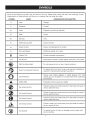
Someof the followingsymbolsmaybe usedon this tool. Pleasestudythemand learntheirmeaning.Proper
interpretation
of thesesymbolswillallowyouto operatethe tool betterandsafer.
SYMBOL
NAME
DESIGNATION/EXPLANATION
V
Volts
Voltage
A
Amperes
Current
Hz
Hertz
Frequency
W
Watt
Power
Minutes
Time
min
Alternating
Current
(cycles
per second)
Type of current
Direct Current
Type or a characteristic
n o
No Load Speed
Rotational speed, at no load
[]
Class II Tool
Double-insulated
.../min
Per Minute
Revolutions,
@
Wet Conditions
Alert
Read The Operator's
O
A
@
@
@
®
of current
construction
strokes, surface speed, orbits etc., per minute
Do not expose to rain or use in damp locations.
Manual
To reduce the risk of injury, user must read and understand
operator's manual before using this product.
Eye Protection
Always wear safety goggles or safety glasses with side
shields and, as necessary, a full face shield when operating
this product.
Safety Alert
Precautions that involve your safety.
No Hands Symbol
Failure to keep your hands away from the blade will result in
serious personal injury.
No Hands Symbol
Failure to keep your hands away from the blade will result in
serious personal injury.
No Hands Symbol
Failure to keep your hands away from the blade will result in
serious personal injury.
No Hands Symbol
Failure to keep your hands away from the blade will result in
serious personal injury.
Hot Surface
To reduce the risk of injury or damage, avoid contact with
any hot surface.
Thefollowingsignalwordsandmeanings
areintendedto explainthe levelsofriskassociatedwiththis
product.
SYMBOL
SIGNAL
MEANING
_,
DANGER:
Indicates an imminently hazardous situation, which, if not avoided, will
result in death or serious injury.
,_
WARNING:
Indicates a potentially hazardous situation, which, if not avoided, could
result in death or serious injury.
CAUTION:
Indicates a potentially hazardous situation, which, if not avoided, may
result in minor or moderate injury.
(Without Safety Alert Symbol) Indicates a situation that may result in
CAUTION:
property damage.
SERVICE
,_
Servicing requires extreme care and knowledge
and should be performed only by a qualified service
technician. For service we suggest you return the product
to your nearest SEARS OR OTHER QUALRED SERVICE
CENTER for repair. When servicing, use only identical
replacement parts.
WARNING:
To avoid serious personal injury, do not
attempt to use this product until you read thoroughly
and understand completely the operator's manual. If
you do not understand the warnings and instructions
in the operator's manual, do not use this product.
Call Sears customer service for assistance.
WARNING:
The operation of any power tool can result in foreign objects being thrown into your eyes, which
can result in severe eye damage. Before beginning power tool operation, always wear safety
goggles or safety glasses with side shields and, when needed, a full face shield. We recommend
Wide Vision Safety Mask for use over eyeglasses or standard safety glasses with side shields.
Always use eye protection which is marked to comply with ANSI Z87.1.
SAVE THESE INSTRUCTIONS
PRODUCT
SPECIFICATIONS
Clutch ................................................................
Chuck ...........................................................
Motor ...............................................................
Switch ..............................
1/2 in. Keyless
19.2 Volt DC
VSR (Variable Speed Reversible)
Gear Train ...............................................................
No Load Speed ....................... 0-400/0-1,400
24 Position
Torque ...................................................................
Charger Input ...................................
420 in.lb.
120 V, 60 Hz, AC only
Charge Rate ..............................................................
1 hour
2 Speed
r/rain. (RPM)
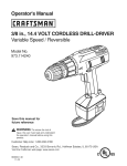
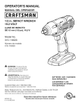
DUAL
LASERS
LEVEL
i
REARViEW
LASER
SWITCH
TWO-SPEED
GEARTRAIN(HI&O)
TORQUE
ADJUSTMENTRING
LEVELS
AUXILIARYHANDLE
ASSEMBLY
KEYLESS
CHUCK
DIRECTIONOFROTATIONSELECTOR
(FORWARD/REVERSE/CENTER
LOCK)
LED
WORKLIGHT
BiT STORAGE
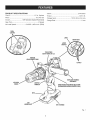
Fig. 1
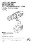
KNOW YOUR
DRILL-DRIVER
KEYLESS
See Figure 1.
The keyless chuck allows you to hand-tighten or release
the drill bit in the chuck jaws.
The safe use of this product requires an understanding of
the information on the tool and in this operator's manual
as well as a knowledge of the project you are attempting.
Before use of this product, familiarize yourself with all
operating features and safety rules.
AUXILIARY
HANDLE
LED WORKLIGHT
The LED worklight, located on the front of the tool base,
illuminates when the switch trigger is depressed. This
provides extra light for increased visibility.
ASSEMBLY
LEVELS
Your drill is equipped with an auxiliary handle for ease of
operation and to prevent loss of control.
Levels are located on the top, sides, and end of the motor
housing to help keep the drill bit level during use.
BIT STORAGE
TORQUE
Bits provided with the drill-driver can be placed in the
storage area, located on the base of the drill.
DIRECTION
OF ROTATION
(FORWARD/REVERSE/CENTER
CHUCK
ADJUSTMENT
RING
Your drill has a 24-position clutch. The torque adjustment
ring can be turned to select the right amount of torque for
your application.
SELECTOR
LOCK)
TWO-SPEED
Your drill has a direction of rotation (forward/reverse/
center lock) selector located above the switch trigger for
changing the direction of bit rotation. Setting the switch
trigger in the OFF (center lock) position helps reduce the
possibility of accidental starting when not in use.
GEAR TRAIN
The two-speed gear train is designed for drilling or driving
at LO (1) or HI (2) speeds. A slide switch is located on top
of your drill for selecting either LO (1) or HI (2) speed.
VARIABLE
SPEED
DUAL LASERS
Dual lasers form 90 ° angles for aligning drill and screw
holes.
The variable speed switch trigger delivers higher speed
with increased trigger pressure and lower speed with
decreased trigger pressure.
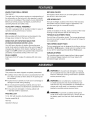
UNPACKING
,_
This product has been shipped completely assembled.
[] Carefully remove the tool and any accessories from the
box. Make sure that all items listed in the packing list
are included.
[] Inspect the tool carefully to make sure no breakage or
damage occurred during shipping.
WARNING:
Do not attempt to modify this tool
or create accessories not recommended for use
with this tool. Any such alteration or modification is
misuse and could result in a hazardous condition
leading to possible serious personal injury.
[] Do not discard the packing material until you have
carefully inspected and satisfactorily operated the tool.
[] If any parts are damaged or missing, please call
1-800-932-3188 for assistance.
PACKING
A
LIST
1/2 in. Drill with Auxiliary Handle Assembly
Double-ended
WARNING:
If any parts are damaged or missing
do not operate this tool until the parts are replaced.
Failure to heed this warning could result in possible
serious personal injury.
Bit (2)
Hex Key
Operator's Manual
10
WARNING:
To prevent accidental starting that
could cause serious personal injury, always remove
the battery pack from the tool when assembling
parts.
CHARGING
_b_ WARNING:Donotallowfamiliaritywithtoolsto
makeyoucareless.Remember
thata careless
fractionofa secondissufficientto inflictserious
injury.
_IL
WARNING:
Always wear safety goggles or safety
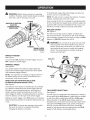
[] Charge the battery pack only with the charger provided.
[] Make sure the power supply is normal household
voltage, 120 volts, 60 Hz, AC only.
Do not use any attachments or
[] Connect the charger to the power supply.
[] Place the battery pack in the charger aligning raised rib
on the battery pack with the groove in the charger. See
Figure 2.
[] Press down on the battery pack to be sure contacts on
the battery pack engage properly with contacts in the
charger.
APPLICATIONS
You may use this tool for the following purposes:
[] Normally the red LED on charger will come on. This
indicates the charger is in fast charging mode.
[] Drilling in wood
[] Drilling in ceramics, plastics, fiberglass, and laminates
[] Red LED should remain on for approximately 1 hour
then the green LED will come on. Green LED on
indicates battery pack is fully charged and charger is
in maintenance charge mode.
[] Drilling in metals
[] Mixing paint
CAUTION:
If at any point during the charging
process none of the LEDs are lit, remove the battery
pack from the charger to avoid damaging the
product. DO NOT insert another battery. Return the
charger and battery to your nearest Sears or other
qualified service center for service or replacement.
NOTE: The green LED will remain on until the battery
pack is removed from the charger or charger is
disconnected from the power supply.
[] If both yellow and green LEDs come on, this indicates
a deeply discharged or defective battery pack. Allow
the battery pack to remain in the charger for 15 to 30
minutes. When the battery pack reaches normal
voltage range, the red LED should come on. If the red
LED does not come on after 30 minutes, this may
indicate a defective battery pack and should be
replaced.
OF CHARGER
LED WILL
BE ON TO INDICATE
CHARGER AND BATTERY PACK:
STATUS
OF
[] Red LED on = Fast charging mode.
[] After normal usage, a minimum of 1 hour of charging
time is required to fully recharge battery pack.
[] Green LED on = Fully charged and in maintenance
charge mode.
[] The battery pack will become slightly warm to the
touch while charging. This is normal and does not
indicate a problem.
[] Green LED on = When battery pack is inserted into
charger, indicates hot battery pack or that battery pack
is out of normal temperature range.
[] Do not place the charger and battery pack in an area
of extreme heat or cold. They will work best at normal
room temperature.
[] Yellow and Green LEDs on = Deeply discharged or
defective battery pack.
NOTE: The charger and battery pack should be placed
in a location where the temperature is more than 50°F
but less than 100°F.
[] No LED on = Defective charger or battery pack.
CHARGING
THE BATTERY
PACK
NOTE: If the charger does not charge the battery pack
under normal circumstances, return both the battery
pack and charger to your nearest Sears or other qualified
service center for electrical check.
accessories not recommended by the manufacturer
of this tool. The use of attachments or accessories
not recommended can result in serious personal
injury.
LED FUNCTIONS
BATTERY
If battery pack is below normal temperature range, the
green LED on charger will come on. Allow battery pack to
reach normal temperature, then the red LED will come on.
glasses with side shields when operating tools.
Failure to do so could result in objects being thrown
into your eyes, resulting in possible serious injury.
41_hLWARNING:
A COOL
PACK
[] When batteries become fully charged, unplug the
charger from power supply and remove the battery
pack.
Battery packs for this tool are shipped in a low charge
condition to prevent possible problems. Therefore, you
should charge it until the green LED on the front of the
charger comes on.
NOTE: Batteries will not reach full charge the first time
they are charged. Allow several cycles (operation followed
by recharging) for them to become fully charged.
11
CHARGINGA
HOT BATTERY
PACK
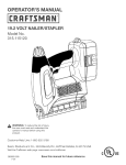
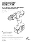
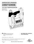
TO INSTALL
BATTERY
PACK
See Figure 3.
When using the tool continuously, the batteries in the
battery pack will become hot. You should let a hot battery
pack cool down for approximately 30 minutes before
attempting to recharge. When the battery pack becomes
discharged and is hot, this will cause the green LED to
come on instead of the red LED. After 30 minutes, reinsert
the battery pack in the charger. If the green LED continues
to remain on, return battery pack to your nearest Sears or
other qualified service center for checking or replacing.
[] Lock switch trigger on the drill by placing the direction
of rotation selector in center position.
[] Place battery pack in the drill. Align raised rib on
battery pack with groove inside drill.
[] Make sure the latches on each side of the battery pack
snap in place and battery pack is secured in drill before
beginning operation.
NOTE: This situation only occurs when continuous use of
the tool causes the batteries to become hot. It does not
occur under normal circumstances. Refer to CHARGING
A COOL BATTERY PACK for normal recharging of
batteries. If the charger does not charge your battery
pack under normal circumstances, return both the battery
pack and charger to your nearest Sears Repair Center for
electrical check.
CAUTION: When placing battery pack in the drill,
be sure raised rib on battery pack aligns with groove
inside drill and latches snap into place properly.
Improper assembly of battery pack can cause
damage to internal components.
TO REMOVE
See Figure 3.
BATTERYPACK
SHOWNIN CHARGER
BATTERY
PACK
[] Lock switch trigger on the drill by placing the direction
of rotation selector in center position.
[] Locate latches on side of battery pack and depress to
release battery pack from the drill.
[] Remove battery pack from the drill.
RED LED
GREENLED
YELLOW LED
BATTERY
PACK
Fig. 2
LATCHES
DEPRESSLATCHESTO
RELEASEBATTERYPACK
12
Fig. 3
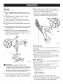
To stop the drill, release the switch trigger and allow the
chuck to come to a complete stop.
_1_ WARNING:Batterytoolsarealwaysinoperating
condition.Therefore,
switchshouldalwaysbelocked
whennot inuseor carryingatyourside.
NOTE: The drill will not run unless the direction of rotation
selector is pushed fully to the left or right.
Avoid running the drill at low speeds for extended periods
of time. Running at low speeds under constant usage may
cause the drill to become overheated. If this occurs, cool
the drill by running it without a load and at full speed.
REVERSE
DiRECTiONOF ROTATION
SELECTOR
(FOWARD/REVERSE/
CENTERLOCK)
KEYLESS CHUCK
See Figure 5.
The drill has a keyless chuck to tighten or release drill
bits in the chuck jaws. The arrows on the chuck indicate
which direction to rotate the chuck body in order to LOCK
(tighten) or UNLOCK (release) the drill bit.
t
,_
FORWARD
VARIABLESPEED
SWITCHTRIGGER
Fig. 4
SWITCH
WARNING:
Do not hold chuck body with one hand
and use power of the drill to tighten chuck jaws on
drill bit. Chuck body could slip in your hand or your
hand could slip and come in contact with rotating
drill bit. This could cause an accident resulting in
serious personal injury.
TRIGGER
UNLOCK
See Figure 4.
DRILLBIT
(RELEASE)
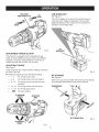
To turn the drill ON, depress the switch trigger. To turn it
OFF, release the switch trigger.
CHUCK
BODY
VARIABLE SPEED
See Figure 4.
The variable speed switch delivers higher speed and
torque with increased trigger pressure and lower speed
with decreased trigger pressure.
NOTE: You might hear a whistling or ringing noise from
the switch during use. Do not be concerned; this is a
normal part of the switch function.
DIRECTION
OF ROTATION
CHUCK
JAWS
LOCK
(TIGHTEN)
SELECTOR
(FORWARD/REVERSE/CENTER
LOCK)
See Figure 4.
The direction of bit rotation is reversible and is controlled
Fig. 5
by a selector located above the switch trigger. With the
drill held in normal operating position, the direction of
rotation selector should be positioned to the left of the
switch trigger for drilling. The drilling direction is reversed
when the selector is to the right of the switch trigger.
TWO-SPEED
See Figure 6.
GEAR TRAIN
The drill has a two-speed gear train designed for drilling or
driving at LO (1) or HI (2) speeds. A slide switch is located
on top of the drill to select either LO (1) or Hi (2) speed.
When using drill in the LO (1) speed range, speed will
decrease and unit will have more power and torque. When
using drill in the HI (2) speed range, speed will increase
and unit will have less power and torque. Use LO (1)
speed for high power and torque applications and HI (2)
speed for fast drilling or driving applications.
Setting the switch trigger in the OFF (center lock) position
helps reduce the possibility of accidental starting when not
in use.
CAUTION: To prevent gear damage, always allow
the chuck to come to a complete stop before
changing the direction of rotation.
13
TWO-SPEED
GEARTRAIN (RI-LO)
LED WORKLJGHT
LO
SPEED
See Figure 8.
The LED worklight on the foot of the drill will come on
when the switch trigger is depressed. This provides
additional lighting on the surface of the workpiece for
operation in lower-light areas.
LED
WORKLIGHT
Fig. 6
ADJUSTABLE
TORQUE
CLUTCH
This product is equipped with an adjustable torque
clutch for driving different types of screws into different
materials. The proper setting depends on the type of
material and the size of screw you are using.
ADJUSTING
TORQUE
See Figure 7.
There are twenty-four
the front of the drill.
torque indicator settings located on
Fig. 8
[] Rotate the adjusting ring to the desired setting.
" 1-4
For driving small screws
BiT STORAGE
See Figure 9.
"
5-8
For driving screws into soft material
"
9-12
For driving screws into soft and hard
materials
"
13 - 16
For driving screws into hard wood
"
17 - 23
For driving large screws
*
_11
When not in use, bits provided with the drill can be placed
in the storage area located on the base of the drill.
For heavy drilling
81TSTORAGEAREA
TOINCREASE
TORQUE
Fig. 7
14
Fig. 9
INSTALLING
BITS
See Figures 10 - 11.
[] Lock the switch trigger by placing the direction of
rotation selector in the center position.
[] Open or close the chuck
opening is slightly larger
use. Also, raise the front
bit from failing out of the
[] Insert the drill bit.
_
WARNING:
jaws to a point where the
than the bit size you intend to
of the drill slightly to keep the
chuck jaws.
Do not insert drill bit into chuck jaws
and tighten as shown in figure 11. This could cause
drill bit to be thrown from drill resulting in possible
serious personal injury or damage to the chuck.
WRONG
[] Tighten the chuck jaws on the drill bit.
[] Rotate the chuck clockwise to tighten the chuck jaws
securely on the bit.
REMOVING
DRILLBIT
[] Lock the switch trigger by placing the direction of
rotation selector in the center position.
[] Rotate the chuck sleeve clockwise to open the chuck
jaws.
CHUCK
BODY
NOTE: Rotate the chuck body in the direction of the
arrow marked UNLOCK to loosen the chuck jaws. Do
not use a wrench to tighten or loosen the chuck jaws.
[] Remove the drill bit.
CHUCK
JAWS
LOCK
(TIGHTEN)
RIGHT
BITS
See Figure 10.
NOTE: Rotate the chuck body in the direction of the
arrow marked LOCK to tighten the chuck jaws. Do not
use a wrench to tighten or loosen the chuck jaws.
UNLOCK
(RELEASE)
Fig. ll
Fig. 10
15
USING
USING
THE LASER GUIDE
,_
THE AUXILIARY
HANDLE
ASSEMBLY
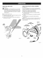
See Figure 13.
See Figure 12.
Your drill is equipped with an auxiliary handle assembly.
For ease of operation, use the handle with either the left or
right hand. The handle can be rotated 360 °.
WARNING:
To avoid possible injury, do not stare
into the laser beam. The laser unit comes from the
factory already installed and aligned, but if the laser
becomes misaligned after time, refer to the Adjustments section.
To adjust the auxiliary handle assembly:
[] Loosen the handle assembly by turning the handle
counterclockwise.
[] Aim the drill toward a wall.
[] Rotate the handle assembly to the desired operating
position.
[] Depress the laser switch. The drill will project two lines
in a 90 ° right angle on the wall.
[] Securely tighten by turning the handle assembly
clockwise.
[] Using the levels to keep laser lines level, project the
laser lines on the wall.
NOTE: For convenience and ease of starting threads, the
hex nut has been trapped inside the molded slot in the
handle assembly.
GROOVE
LASER
SWITCH
AUXILIARY
HANDLEASSEMBLY
TO
TIGHTEN
Fig. 12
LOOSEN
360°
ROTATION
Fig. 13
16
DRiLLiNG
[] When drilling metals use a light oil on the drill bit to
keep it from overheating. The oil will prolong the life of
the bit and increase the drilling action.
See Figures 14- 15.
[] Depress and release the switch trigger to be sure the
drill is in the OFF position before connecting it to power
supply.
[] Check the direction of rotation selector for correct
setting (forward or reverse).
[] Secure the material to be drilled in a vise or with
[] If the bit jams in the workpiece or if the drill stalls,
stop the tool immediately. Remove the bit from the
workpiece and determine the reason for jamming.
LEVELS
clamps to keep it from turning as the drill bit rotates.
[] Plug the drill into power supply source.
[] Hold the drill firmly and place the bit at the point to be
drilled.
[] Depress the switch trigger to start the drill. Do not lock
the switch ON for jobs where the drill may need to be
stopped suddenly.
[] Move the drill bit into the workpiece applying only
enough pressure to keep the bit cutting. Do not force
the drill or apply side pressure to elongate a hole. Let
the drill and bit do the work.
LEVEL
LEVELS
Fig. 15
WOOD
DRILLING
For maximum performance,
wood drilling.
use high speed steel bits for
[] Begin drilling at a very low speed to prevent the bit
from slipping off the starting point. Increase the speed
as the drill bit bites into the material.
[] When drilling through holes, place a block of wood
behind the workpiece to prevent ragged or splintered
edges on the back side of the hole.
METAL
For maximum performance,
metal or steel drilling.
Fig. 14
,_
WARNING"
DRILLING
use high speed steel bits for
[] Begin drilling at a very low speed to prevent the bit
from slipping off the starting point.
Be prepared for binding at bit
breakthrough. When these situations occur, drill has
a tendency to grab and kick opposite to the direction
of rotation and could cause loss of control when
[] Maintain a speed and pressure which allows cutting
without overheating the bit. Applying too much
pressure will:
breaking through material. If not prepared, this loss
of control can result in possible serious injury.
• Overheat the drill;
Wear the bearings;
[] When drilling hard smooth surfaces use a center punch
to mark the desired hole location. This will prevent the
drill bit from slipping off center as the hole is started.
Bend or burn bits; and
Produce off-center or irregular-shaped
holes.
[] When drilling large holes in metal, start with a small bit,
then finish with a larger bit. Also, lubricate the bit with
oil to improve drilling action and increase bit life.
17
_
CAUTION:Useofcontrolsor adjustments
or performanceofprocedures
otherthanthosespecified
hereinmayresultinhazardous
radiationexposure.
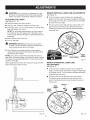
ADJUSTINGTHE LASER
MAKING
VERTICAL
LASER LINE ADJUSTMENTS
See Figure 16.
[] The front screw
angle. Turn the
of the laser line
the laser line to
See Figures 16- 18.
[] Remove battery pack from the drill.
moves the laser line, changing the
screw clockwise to angle the top edge
to the left. Counterclockwise will angle
the right.
[] The rear screw moves the laser line right to left. Turning the screw clockwise moves the laser line right.
Counterclockwise moves the laser line left along the
horizontal axis.
[] Facing a wall, center the bubble in the top level.
[] Clamp the drill in a vice or other clamp so that the laser
lines will project onto a wall.
NOTE: For accurate measurements, do not exceed a
3 ft. distance from the nearest wall. Otherwise, laser
lines may not intersect properly for perpendicular measurements.
[] Place battery pack in the drill.
[] Turn on the laser.
_1_ WARNING:
DO NOT point the laser at yourself
or others. Class Ilia lasers will burn the retinas and
could cause serious injury to the eyes.
[] Use a level and a framing square to take measurements of the laser lines on the wall to determine what
adjustments are needed.
NOTE: Use a level to check the horizontal and vertical
laser lines. A framing square or level can be used to check
if the laser lines are perpendicular. The laser lines should
project a 90 ° angle.
HEXKEY
FRONTSCREW
REAR
SCREW
Fig. 17
MAKING HORIZONTAL
ADJUSTMENTS
Make adjustments with the drill clamped in place and the
lasers facing away from the user.
LASER
LINE
See Figure 17.
[] The front screw rotates the laser line to change the
angle. Turn the screw clockwise to angle the right edge
of the laser line up. Turn the screw counterclockwise to
angle the laser line down.
[] The rear screw moves the laser line up and down.
Turning the screw clockwise moves the laser line
down. Counterclockwise moves the laser line up the
vertical axis.
----q
HEXKEY
REAR
SCREW
FRONT
SCREW
\
(
Fig. 16
315,115440
Fig. 18
18
,_IL WARNING:
When servicing, use only identical
GENERAL
Craftsman replacement parts. Use of any other part
may create a hazard or cause product damage.
,_
WARNING:
Avoid using solvents when cleaning plastic parts. Most
plastics are susceptible to damage from various types of
commercial solvents and may be damaged by their use.
Use clean cloths to remove dirt, dust, oil, grease, etc.
Always wear safety goggles or safety
glasses with side shields when using compressed air
to clean tools. If the operation is dusty, also wear a
dust mask.
_L
WARNING:
MAINTENANCE
_
WARNING:
Do not at any time let brake fluids,
gasoline, petroleum-based products, penetrating
oils, etc., come in contact with plastic parts.
Chemicals can damage, weaken or destroy plastic
which may result in serious personal injury.
To avoid serious personal injury, always
remove the battery pack from the tool when cleaning
or performing any maintenance.
Only the parts shown on the parts list are intended to be
repaired or replaced by the customer. All other parts
should be replaced at a Sears Service Center.
BATTERIES
BATTERY
PACK
FOR RECYCLING
The battery pack for this tool is equipped with nickelcadmium rechargeable batteries. Length of service from
each charging will depend on the type of work you are
doing.
REMOVAL
AND
PREPARATION
To preserve natural resources, please
recycle or dispose of batteries
properly.
This product contains nickel-cadmium
batteries. Local, state or federal
laws may prohibit disposal of nickelcadmium batteries in ordinary trash.
The batteries in this tool have been designed to provide
maximum trouble-free life. However, like all batteries, they
will eventually wear out. Do not disassemble battery pack
and attempt to replace the batteries. Handling of these
batteries, especially when wearing rings and jewelry, could
result in a serious burn.
Consult your local waste authority for information
regarding available recycling and/or disposal options.
To obtain the longest possible battery life, we suggest the
following:
,_
For battery pack storage longer than 30 days:
[] Store battery packs in a "discharged"
Upon removal, cover the battery pack's
terminals with heavy-duty adhesive tape. Do not
attempt to destroy or disassemble battery pack or
remove any of its components. Nickel-cadmium
batteries must be recycled or disposed of properly.
Also, never touch both terminals with metal objects
and/or body parts as short circuit may result. Keep
away from children. Failure to comply with these
warnings could result in fire and/or serious injury.
[] Remove the battery pack from the charger once it is
fully charged and ready for use.
[] Store the battery pack where the temperature
80°F.
WARNING:
is below
condition.
19
CHUCK REMOVAL
Insert the hex key into the chuck and tighten the
chuck jaws securely. Tap sharply with a mallet in a
counterclockwise direction. This will loosen the chuck
on the spindle. It can now be unscrewed by hand.
See Figures 19 - 21.
The chuck may be removed and replaced by a new one.
[] Lock the switch trigger by placing the direction of
rotation selector in center position.
MALLET
[] Insert a 5/16 in. or larger hex key into the chuck of the
drill and tighten the chuck jaws securely.
[] Tap the hex key sharply with a mallet in a clockwise
direction. This will loosen the screw in the chuck for
easy removal.
MALLET
Fig. 21
TO RETIGHTEN
HEXKEY
A LOOSE
CHUCK
The chuck may become loose on the spindle and develop
a wobble. Also, the chuck screw may become loose,
causing the chuck jaws to bind and prevent them from
closing. To tighten:
KEYLES8
CHUCK
[] Lock the switch trigger by placing the direction of
rotation selector in the center position.
Fig. 19
[] Open the chuck jaws.
[] Insert the hex key into the chuck and tighten the chuck
jaws securely. Tap the hex key sharply with a mallet in
a clockwise direction. This will tighten the chuck on the
spindle.
[] Open the chuck jaws and remove the hex key. Using a
screwdriver, remove the chuck screw by turning it in a
clockwise direction.
NOTE: The chuck screw has left hand threads.
[] Open the chuck jaws and remove the hex key.
[] Tighten the chuck screw.
Fig. 20
2O
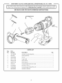
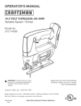
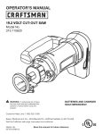
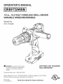
CRAFTSMAN19,2VOLTCORDLESSDRILL=DRIVERMODELNO,315.115440
-
The model number will be found
number in all correspondence
attached
to oto hou 0 }
the
mention the model
regarding your CORDLESS DRILL=DRIVER
SEE BACK PAGE FOR PARTS ORDERING
or when ordering repair parts.
w
iNSTRUCTiONS
3
\
"4
5
6
PARTS LiST
Key
No.
Part
Number
Description
1
300188028
Auxiliary Handle Assembly ..................................................................
1
2
6613402
Screw (Special) ....................................................................................
1
3
690033066
Chuck ..................................................................................................
1
4
940114128
Logo Label ..........................................................................................
1
5
940237108
Data Label A ........................................................................................
1
6
940237109
Data Label B ........................................................................................
1
7
6782102
Double Ended Bit (PH #2 & #3) ...........................................................
1
8
671842001
Hey Key (1/16 in.) ................................................................................
1
9
670824003
Double Ended Bit (SLOT 6 & 7) ...........................................................
1
983000852
Operator's Manual
Qty.
21
Your Home
For repair-in
your home-of all major brand appliances,
lawn and garden equipment, or heating and cooling systems,
no matter who made it, no matter who sold it!
For the replacement parts, accessories and
owner's manuals that you need to do-it-yourself.
For Sears professional installation of home appliances
and items like garage door openers and water heaters.
1-800-4-MY-HOME
Call anytime,
®
(1-800-469-4663)
day or night (U.S.A. and Canada)
www.sears.com
www.sears.ca
Our Home
For repair of carry-in items like vacuums, lawn equipment,
and electronics, call or go on-line for the location of your nearest
Sears Parts & Repair Center.
1-800-488-1222
Call anytime,
day or night (U.S.A. only)
www.sears.com
To purchase a protection agreement (U.S.A.)
or maintenance agreement (Canada) on a product serviced
1-800-827-6655
(U.S.A.)
Para pedir servicio de reparaci6n
a domicilio, y para ordenar piezas:
1-888-SU-HOGAR
1-800-361-6665
Au Canada
by Sears:
(Canada)
pour service en frangais:
1-800-LE-FOYER
sM
Mc
(1-800-533-6937)
www.sears.ca
(1-888-784-6427)
Sesi/
® Registered
Trademark
/
TM
Trademark
/
SM
Service
Mark of Sears, Roebuck
® Marca Registrada / TM Marca de F&brica / s_4Marca de Servicio de Sears,
MC Marque de commerce / MDMarque dCpos_e de Sears, Roebuck and Co.
and Co.
Roebuck
and Co.
® Sears,
Roebuck
and Co.