1
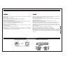
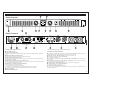
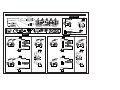
TWIN CHANNEL POWER AMPLIFIER
ETAPA DE POTENCIA DOS CANALES
USER MANUAL
MANUAL DE USUARIO
AMD-240
AMD-400
FEATURES / CARACTERÍSTICAS
ENGLISH
ESPAÑOL
ESPAÑOL
► Tres posibles modos de operacion: estéreo, paralelo y bridged mono.
Permiten una aplicación flexible de la etapa de potencia.
► Una unidad de RACK
► Control independiente de nivel de salida para cada canal. Nos permite un
ajuste óptimo del nivel.
► Sensibilidad de entrada seleccionable entre 0.775V, 1V, 1.4V.
► Funcionamiento a 4 & 8 Ohmios.
► Precisos testigos luminosos (LEDs) nos permiten ver en tiempo real el
funcionamiento de la etapa y ajustar los niveles para evitar saturación.
► Sistema de refrigeración dotado de dos ventiladores sensibles a la
temperatura para mantener en todo momento la temperatura óptima de
trabajo del equipo.
► Conexiones de entrada; Canon (XLR) Balanceadas
► 4 (2x2) “Binding Posts” para conexión a cajas acústicas.
► Speakon® en cada canal para conexión a cajas acústicas.
► Transformador toroidal de alta corriente de gran fiabilidad y estabilidad.
► Protección contra corriente continua (DC) y Saturación (Overload)
independientes en cada canal proporcionando protección a la etapa y los
altavoces.
ENGLISH
► Two-channel, parallel or bridged mono operating modes for flexible
application.
► One RACK unit assembly.
► Independent limiters for each channel reduce distortion.
► Selectable Input Sensitivity between 0.775V, 1V, 1.4V.
► 4 & 8 Ohm operation load.
► Precise signal and clip led indicators to monitor performance, allow you
to correct for overloading (clipping) condition.
► Two temperature controlled fans for better cooling.
► Balanced XLR input connectors.
► Four-way (2x2) output binding posts or speaker connectors enable
secure operation.
► Speakon® Output for each channel.
► H i g h - c u r r e n t t o r o i d a l t r a n s f o r m e r f o r a b s o l u t e r e l i a b i l i t y.
► Independent DC and thermal overload protection on each channel
automatically protects amplifier and speaker.
WIRING/CONECTORES
XLR Balanced Wiring Guide
Speakon® Output Connector
OUTPUT (Mixer)
INPUT (Power Amplifier)
1= ground/shield
2= hot
1= (+ve)
ground/shield
3= cold
(-ve)
2= hot
(+ve)
3= cold (-ve)
for unbalanced use pin 1 and pin 3 to be bridged
para uso no balanceado el pin 1 y el pin 3 deben ser puenteados
1
ENGLISH
WARNING
TO PREVENT FIRE OR SHOCK HAZARD. DO NOT USE THIS PLUG WITH AN EXTENSION CORD, RECEPTACLE OR OTHER OUTLET UNLESS THE BLADES CAN BE FULLY INSERTED TO PRESENT BLADE TO
PREVENT FIRE OR SHOCK HAZARD. DO NOT EXPOSE THISAPPLIANCE TO RAIN OR MOISTURE. TO PRVENT ELECTRICAL SHOCK, MATCH WIDE BLADE PLUG TO WIDE SLOT FULLY INSERT.
CAUTION
RISK OF ELECTRIC SHOCK
DO NOT OPEN
CAUTION: To reduce the risk of electric shock, do not
remove any cover. No user-serviceable parts inside. Refer
servicing to qualified service personnel only.
1. Read Instructions All the safety and operating instructions should be read before this product is
operated.
2. Retain Instructions. The safety and operating instructions should be retained for future reference.
3. Heed Warnings. All warnings on the appliance and in the operating instructions should be adhered
to.
The lightning flash with arrowhead symbol within the
equilateral triangle is intended to alert the use to the
presence of un-insulated “dangerous voltage” within
The exclamation point within the equilateral triangle is
intended to alert the user to the presence of important
operation and maintenance (servicing) instructions in
the literature accompanying this appliance.
from both AC plug blades to all exposed metallic parts. The resistance should be more than
100,000 ohms.
14. Non-use Periods. The power cord of the appliance should be unplugged from the outlet when left
unused for a long period of time.
15. Object and Liquid Entry. Care should be taken so that objects do not fall and liquids are not spilled
into the enclosure through openings.
4. Follow Instructions. All operating and use instructions should be followed.
5. Water and Moisture. The appliance should not be used near water - for example, near a bathtub,
washbowl, kitchen sink, laundry tub, in a wet basement, or near a swimming pool, and the like.
6. Carts and Stands . The appliance should be used only with a cart or stand that is recommended by
the manufacturer.
An appliance and cart combination should be moved with care. Quick stops, excessive force, and
uneven surfaces may cause the appliance and cart combination to overturn.
16. Damage Requiring Service. The appliance should be serviced by qualified service personnel
when:
A: The power-supply cord or the plug has been damaged; or
B: Objects have fallen, or liquid has been spilled into the appliance; or
C: The appliance has been exposed to rain; or
D:The appliance does not appear to operate normally or exhibits a marked change in performance;
or
E: The appliance has been dropped, or the enclosure damaged.
7. Wall or Ceiling Mounting. The product should be
recommended by the manufacturer.
mounted to a wall or ceiling only as
8. Heat. The appliance should be situated away from heat sources such as radiators, heat registers,
stoves, or other appliances (including amplifiers) that produce heat.
9. Power Sources This product should be operated only from the type of power source indicated on
the rating label. If you are not sure of the type of power supply to your home, consult your
product dealer or local power company. For products intended to operate from battery power, or
other sources, refer the operating instructions.
10. Grounding or Polarization This product may be equipped with a polarized alternation-current
line plug (a plug having one blade wider than the other). This plug will fit into the power outlet
only one way. This is a safety feature. If you are unable to insert the plug fully into the outlet, try
reversing the plug. If the plug should still fail to fit, contact your electrician to replace your
obsolete outlet. Do not defeat the safety purpose of the polarized plug.
11. Power-Cord Protection. Power-supply cords should be routed so that they are not likely to be
walked on or pinched by items placed upon or against them, paying particular attention to the
cord in correspondence of plugs, convenience receptacles, and the point where they exit from the
appliance.
12. Cleaning - The appliance should be cleaned only as recommended by the manufacturer. Clean
by wiping with a cloth slightly damp with water.Avoid getting water inside the appliance.
13. For AC line powered units - Before returning repaired unit to user, use an ohm-meter to measure
18. Ventilation Slots and openings in the cabinet are provided for ventilation and to ensure reliable
operation of the product and to protect it from overheating, and these openings must not be
blocked or covered. The openings should never be blocked by placing the product on a bed, sofa,
rug, or other similar surface. This product should not be placed in a built-in installation such as a
bookcase or rack unless proper ventilation is the manufacturer's instructions have been adhered
to.
ENGLISH
17. Servicing. The user should not attempt any service to the appliance beyond that described in the
operating instructions.All other servicing should be referred to qualified service personnel.
19. Attachments do not use attachments not recommended by the product manufacturer as they may
cause hazards.
20. Accessories Do not place this product on an unstable cart, stand, tripod, bracket, or table. The
product may fall, causing serious injury to a child or adult, and serious damage to the product. Use
only with a cart, stand, tripod, bracket, or table recommended by the manufacturer, or sold with
the product. Any mounting of the product should follow the manufacturer's instructions, and
should use a mounting accessory recommended by the manufacturer.
20. Lightning For added protection for this product during a lightning storm, or when it is left
unattended and unused for long periods of time, unplug it from the wall outlet and disconnect the
antenna or cable system. This will prevent damage to the product due to lightning and power-line
surges.
22. Replacement Parts When replacement parts are required, be sure the service technician has used
replacement parts specified by the manufacturer or have the same characteristics as the original
part. Unauthorized substitutions may result in fire, electric shock, or other hazards.
23. Safety Check Upon completion of any service or repairs to this product, ask the service
technician to perform safety checks to determine that the product is in proper operating condition.
2
given and if noise is given (saturation at mixer), it will be
amplified. Naturally, that is bad.
15 min, Read me!
Before unwrapping and starting your PowerAmplifier there are a few thinks you should know…
Setting input levels at the mixer: Gain pot adjusts the input sensibility or so to speak the level of
the input signal inside the mixer. It is paramount to set the right input level on every channel.
Why is so important setting the correct input level?
First, we have to understand the concept of Dynamic Range of an audio signal. The Dynamic
Range of an audio signal is defined as the ratio between the maximum level before distortion and
the minimum audible level. It is measured in decibels and gives us an idea of the amplitude of the
signal.
Dynamic Range
Pic (Transient)
Power amplifiers and loudspeakers: Current professional power amplifiers are quite
reasonably protected against signal deterioration and excessive levels and shortcuts.
Loudspeakers are not that well protected, hence a rule or some must be devised to use the correct
speakers with a given power amplifier.
Well, that rule is not a straightforward statement but more of an understanding of the principles
and nature of the audio signal. The nature of the audio signal reefer to the type of music you are
playing and more specifically of its Dynamic Range. The bigger the Dynamic Range the bigger
the power amplifier needed. If the Dynamic Range of a give audio signal is big, the difference
between the minimum level and maximum level of this audio signal will be big as well. Therefore,
we will need an oversized power amplifier with enough power to amplify the maximum levels
without reaching the saturation level at the power amplifier (normally, power amplifiers have red
LEDs to let you know when they start saturating).
As a vague rule we can say that Rock and highly compress music require a power amplifier
delivering a power value slightly bigger than the rated maximum power of the speakers. However,
we recommend the power amplifier rated power be 1.5 times bigger than the rated maximum
power of the speakers. Example: if the power amplifier rated power is 200W RMS at 8Ω , the rated
maximum power of the speakers should be 200x1/1,5=133,4W RMS at 8Ω.
Using the power amplifier: Saturation and input levels. In order to make the most of your power
amplifier you must watch two things:
Dynamic range
Ratio: Max. Level vs. Minimum audible level
3
Electroacoustic Signal
1- Set the volume controls in a way that the saturation LED lights up only occasionally (peaks).
2- Feed the power amplifier with an audio signal of the appropriate level. What is the appropriate
level? Professional Power Amplifiers are set for an input level of 4 dBu. Do not panic, it is easy to
get to it. 4 dBu is just a fixed measure of the audio signal that professional audio community uses
as reference level, it can be expressed also in Volts 4dBu equals 1.23 Volt RMS. So to speak, the
Power Amplifier will work at its best if feed with a signal of a level near the 4 dBu or 1.23 Volt
RMS. How do we set this level? Easy, using the mixer appropriately. Incidentally, the nominal
level for a professional audio mixer is also 4dBu. Therefore, if we set the master output level of the
mixer carefully monitoring the output level meters (normally LED bars), we will ensure that the
level of the audio signal fed to the Power Amplifier is near 4dBu because the nominal level of the
mixer is 4dBu and we set correctly the output level or the mixer.
2
Minimum audible level
1
0
1
2
3
4
5
6
7
8
Time
We have to acknowledge that a professional audio system
is a serial bounded group of professional audio devices and
that saturation or other signal deterioration present in one
device will appear someway or another at the serial
bounded following devices.
If we deliver saturated signal from the mixer to the power
amplifier we will not be able to get rid of this saturation
whatsoever. The power amplifier will amplify all what is
HEADROOM
SATURATION
!
Why we should avoid saturation?
Obvious reasons aside there is a more “material” reason. Saturated signal can damage your
speakers. Although some speakers have overload protection, a highly saturated signal can deliver
D.C. and this phenomenon can easily shatter your speakers.
SIGNAL
DYNAMIC RANGE
RATIO SIGNAL/NOISE
We want the audio signal to fluctuate away from the
maximum level (distortion begins) and away from the
minimum level (or background level), where some
noise is present due the nature of the ICs used in the
electronic circuit (all ICs induce noise into the audio
signal).
At the draw, we depict this “safe” level within two
discontinue lines.
We have to set the level of input signal so that the signal
peaks do not reach saturation levels and the lower
amplitude parts of the signal are not too near the
background noise level.
ENGLISH
Level or amplitude
4
NOISE
3
CONTROLS
Front panel
STEREO
PARALLEL
BRIDGE
4-8 OHM
INPUT SENSITIVITY
0.775V
1V 1.4V
TWO CHANNEL POWER AMPLIFIER
8
Rear panel
BRIDGE
(BRIDGE)
BRIDGE
CH-B
CH-A
CH-B
SENSITIVITY
CONNECT
CH-B
CH-A
CH-A
CONNECT
CH-B
AKIYAMA. 08191 BARCELONA (SPAIN)
SPEAKON
INPUTS
OUTPUTS
FRONT PANELCONTROLS
REAR PANELCONTROLS
1 Power ON/OFF switch
2 CHA/CHB input level control
When amplifier works in Bridged and Parallel mode, only CHAworks, CHB is disabled.
3 Power on indicator lamp ( Blue)
When the amplifier works steadily, the led lights.
4 Signal level indicator (Yellow)
The Led light when amplifier works in normal condition. The output power. Is higher, the light is
stronger.
5 CHA, CHB peak value indicator lamps(Orange)
The LED light when amplifier reaches is clipping level. Please adjust the input leveltill the cli LED
flasheds, it mean that the amplifier works in normal condition.
6 CHA, CHB protect indicator lamps(Red)
The LED will be light in the three situations:
1)When amplifier overload or short circuit.
2) When the power transistors temperature is over 90 degrees Celcius.
3) Something is wrong with the amplifier.
7 Air grill
8 Rack mount ears
Two front panel mounting holes are provided on each mounting ear.
1 Power socket
IEC connector forAC power cable. Connect the supplied heavy-gauge 3-pin IECpower cable.
2 Input voltage selector
For Europe use 230.
3 CHA/CHB speaker output
Loudpeakers connections. More info at page 8.
4 CHA/CHB binding post output
Loudpeakers connections. More info at page 8.
5 CHA/CHB XLR input
Connect the input source to these electronic balanced connectors.
6 Mode selection switch
Selects operation mode. More info at page 10.
7 Sensitivity slection switch.
Selects Power Amplifier Input Sensitivity. More info at page10.
8 Intelligent fan
Two speed temperature sensible fans.
ENGLISH
CH-A
4
ATENCIÓN
PARA EVITAR RIESGO DE ELECTROCUCIÓN ASEGÚRESE DE QUE EN CASO DE NO USAR UNA CONEXIÓN AC CON TOMA DE TIERRA LOS CONECTORES DE TOMA DE TIERRA DEL
ENCHUFE DEL EQUIPO NO QUEDEN EXPUESTOS.
CAUTION
RISK OF ELECTRIC SHOCK
DO NOT OPEN
ATENCIÓN: para reducir el riesgo de electrocución, no
manipule el interior del equipo.
Para realizar el mantenimiento del equipo póngase en contacto
con el personal cualificado
Esta señal indica la presencia de lugares donde
habiendo un elevado voltaje no presentan
aislamiento y por tanto constituye un claro
riesgo de electrocución.
Esta señal indica la presencia de componentes
del equipo que precisan de mantenimiento. Para
más información sobre éstos lea el manual.
1. Lea detenidamente este manual antes de utilizar su equipo.
distribuidor.
2. Mantenga el manual a su disposición para su uso en el futuro.
15. Daños en el quipo que precisen reparación. El equipo deberá ser reparado o revisado por personal
cualificado en caso de:
A. El cable de toma de corriente o su conector han sido dañados.
B. Objetos o líquidos se han introducido en el equipo.
C. El aparato ha sido expuesto a la lluvia.
D. El equipo no parece funcionar o lo hace de modo poco usual.
E. El aparato ha caído al suelo o presenta deterioros en su caja exterior.
3. Siga las advertencias que se le proporcionan en este manual.
4. Siga las instrucciones consignadas en este manual, un uso indebido podría dejar sin efecto la
garantía.
5. Agua y humedad. No utilice el equipo cerca del agua o en lugares muy húmedos (fregadero,
lavadora, etc.) para evitar riesgos de descarga eléctrica o fuego.
17. Ventilación. El aparato está provisto de hendiduras de ventilación, es importante no cubrirlas o
bloquearlas. La ventilación del aparato podría verse comprometida resultando en un
sobrecalentamiento que podría dañar el equipo. Tenga siempre en cuenta que colocar el aparato en un
lugar sin ventilación puede producir un sobrecalentamiento de éste.
ESPAÑOL
6.Transporte del equipo. Transporte el equipo con mucho cuidado. Los golpes o las vibraciones
fuertes pueden dañarlo mecánicamente.
16. Mantenimiento. No abra el equipo para labores de mantenimiento pues en este aparato no hay
piezas que necesiten manutención. En caso de que abriendo el equipo sea éste dañado o lo sea la
persona que lo manipula la empresa no tomará ninguna responsabilidad por este servicio de
mantenimiento no autorizado.Además en éste caso la garantía perdería su vigencia.
7. Montaje en pared o techo. Siga las instrucciones del fabricante.
8. Fuentes de calor. Tenga cuidado de no colocar el equipo cerca de fuentes de calor (Ej. Radiadores,
estufas, amplificadores)
9. Voltaje. Antes de conectar el aparato a la red asegúrese de que se trata del mismo voltaje y
frecuencia para las que el equipo está especificado. En caso contrario no conecte el equipo y
póngase en contacto con su distribuidor.
10. Protección del cable. Escoja una posición para el cable de corriente de modo que esté lo menos
expuesto a pisotones y demás agresiones. Especial atención con los dos extremos del cable de toma de
corriente, la clavija de enchufe a la red y la clavija de alimentación del equipo.
11. Limpieza. Desconecte el equipo antes de realizar alguna operación de limpieza del aparato. Utilice
un trapo suave y seco para limpiar. Asegúrese de que los cables están correctamente conectados antes
de volver a enchufar el aparato.
12. Control de seguridad. La diferencia de potencial entre la toma de corriente de la pared y cualquier
pieza metálica del equipo debe ser de al menos 100.000 ohmios.
18. Nunca utilice accesorios o modificaciones no autorizados por el fabricante. Ello puede afectar la
seguridad del aparato y el fabricante no tendrá ninguna responsabilidad en este caso.
19. Accesorios. No deposite o instale el equipo sobre superficies o estructuras inestables. El aparato
podría precipitarse y causar lesiones a las personas en las proximidades de éste. Cualquier montaje o
instalación del equipo deberá ser realizado siguiendo las instrucciones o recomendaciones dadas en
este manual o por el fabricante directamente.
20. Precaución durante tormentas. Durante una tormenta desconecte el equipo de la red para evitar que
los posibles picos de corriente dañen el equipo.
21. Durante cualquier manipulación del equipo, para mantener todas las cualidades de éste tanto en
prestaciones como en seguridad para el operante es necesario utilizar sólo recambios originales.
Consecuentemente asegúrese de que la empresa que realice el mantenimiento esté autorizada por el
fabricante o importador.
22. Comprobación de seguridad. Una vez realizada una reparación o servicio del equipo pida al
personal cualificado que realice una comprobación para asegurarse de que el equipo le es devuelto en
perfectas condiciones de uso.
13. Periodos largos de reposo del equipo. Desconecte el equipo de la red en caso de reposo prolongado.
14. Líquidos y objetos extraños. En caso de que algún fluido o pequeñas partículas sólidas sean
derramadas sobre el aparato y se introduzcan en los circuitos apague el aparato y llévelo a su
5
capacidad de 200x1/1,5=133,4W RMS a 8Ω.
15 minutos, ¡Léame!
Antes de comenzar a utilizar su etapa de potencia es muy importante que lea esta mínima
introducción escrita con el propósito de ayudarle a obtener el máximo partido de su equipo.
Para una óptima utilización del conjunto etapa-cajas el factor de sobredimensionado de la etapa
deberá ser de 2. Es decir, una etapa de 200 W RMS a 8Ω por canal alimentará a dos cajas de 8Ω con
capacidad para 100 W RMS cada una.
Operación de la etapa de potencia: Saturación y niveles de entrada
Protección de etapa de potencia y cajas acústicas
Respecto de la protección contra daños a su etapa de potencia no hay mucho que decir porque ésta
está diseñada de forma que sus distintos circuitos de protección la inmunizan de posibles
deterioros. Pero sus cajas acústicas nos disponen de estas ventajas…
¿Qué cajas pongo? Aunque parezca mentira no existe una regla precisa al respecto. Y, es que en
realidad no puede existir tal regla dado que todo dependerá del tipo de música que reproduzcamos.
Más en concreto, dependerá de su dinámica. ¿Qué es la dinámica de una señal? A continuación
veamos un gráfico Potencia vs. Tiempo de cómo se comporta la música o mejor dicho la señal
electroacústica asociada a ésta.
Para aprovechar al máximo la etapa deberemos ajustar los controles de nivel de entrada de modo
que los LED de saturación “CLIP” solo se iluminen ocasionalmente. Las etapas AMD tienen un
nivel de entrada nominal de 4 dBu (es un nivel de señal de 1,23 V RMS que corresponde al estándar
de nivel de línea para uso profesional). Es decir, nuestra etapa trabajará en óptimas condiciones
cuando la señal de salida de su mezclador hacia la etapa es de 4 dBu. La mayoría de mezcladores
profesionales tienen un nivel nominal de 4 dBu, así pues, para que la señal entrante en la etapa sea
la óptima simplemente asegúrese de no saturar la señal de salida del mezclador (utilice los LEDs
de nivel del mezclador). Lo adecuado es que los LED rojos (saturación) sólo se enciendan
ocasionalmente.
Recuerde que si enviamos a la etapa señal saturada del mezclador, aunque atenuemos los
controles de ganancia de entrada de la etapa la señal seguirá estando saturada. Y el resultado de la
amplificación no será satisfactorio pues estamos amplificando una señal ya saturada.
Rango Dinámico
Pico (Transient)
¿Por qué debemos evitar la saturación? La señal saturada no sólo suena mal sino que puede
destruir nuestras cajas acústicas. No vamos a extendernos en este tema, simplemente utilice los
indicadores LED de la mesa de mezclas y etapa de potencia para evitar la saturación.
4
3
Señal electroacústica
ESPAÑOL
Nivel o amplitud
Rango Dinámico
Ratio Nivel máximo vs. Nivel mínimo audible
2
Nivel mínimo audible
1
0
1
2
3
4
5
6
7
8
Tiempo
El rango dinámico es el ratio o cociente entre la señal más alta (sin llegar a distorsión) y la señal
audible más baja. Se expresa en decibelios y nos da una idea de la amplitud de la señal. Una
medida equivalente es el ratio S/N (Signal/Noise o Señal/Ruido).
!
SEÑAL
RANGO DINAMICO
RATIO SEÑAL/RUIDO
HEADROOM
SATURACION
Cuando mayor sea el rango dinámico más deberemos
sobredimensionar la etapa de potencia. ¿Por qué? Al ser
mayor el rango dinámico de la señal entrante (ésta
presenta gran diferencia de niveles a lo largo del tiempo) la
etapa puede llegar a saturación con facilidad, para evitar
esta situación debemos disponer de más potencia para
poder amplificar eficientemente la señal entrante sin que
ésta sature la etapa (los LED “CLIP” de la etapa indican
saturación). Por regla general podemos considerar que la
música rock y la música altamente comprimida
necesitarán unas cajas acústicas con una capacidad de
potencia sólo algo inferior a la capacidad de la etapa de
potencia, aunque nosotros recomendamos que se aplique
un factor de 1.5. Es decir, si nuestra etapa proporciona
200W RMS a 8Ω, la caja acústica deberá tener una
RUIDO
6
FUNCIONES
Panel Frontal
STEREO
PARALLEL
BRIDGE
4-8 OHM
INPUT SENSITIVITY
0.775V
1V 1.4V
TWO CHANNEL POWER AMPLIFIER
8
Panel Trasero
BRIDGE
(BRIDGE)
BRIDGE
CH-B
CH-A
CH-B
SENSITIVITY
CONNECT
CH-B
CH-A
CH-A
CONNECT
CH-B
AKIYAMA. 08191 BARCELONA (SPAIN)
SPEAKON
INPUTS
OUTPUTS
CONTROLES EN PANELFRONTAL
Cada pieza dispone de dos agujeros para el montaje en Rack.
1 Conmutador ON/OFF
2 Control nivel CHA & CHB
Cuando la etapa de potencia trabaja en modo “Bridge” o “Parallel” sólo funcionará CHA, CHB no está
activo.
3 Indicador luminoso de encendido (Azul)
Cuando la etapa de potencia está en marcha el LEDAzul se ilumina.
4 Indicador de nivel de señal (Amarillo)
El LED se ilumina cuando la etapa de potencia trabaja a un nivel adecuado, a mayor potencia mayor
intensidad luminosa del LED.
5 Indicador de saturación para CHA & CHB (Naranja)
El LED se ilumina cuando la etapa de potencia satura, ajuste el nivel de entrada de modo que el LED
sólo se encienda ocasionalmente (parpadea).
6 Indicador de protección para CHA & CHB (Rojo)
El LED se ilumina en tres posible situaciones:
1) Cuando existe una sobrecarga o un cortocircuito.
2) Cuando los transistores de potencia alcanzan una temperatura superior a 90 grados.
3) Cuando aparece un problema indeterminado en el aparato del que éste se protege.
7 Reja de ventilación
8 Piezas para montaje en Rack
CONTROLES EN PANELTRASERO
ESPAÑOL
CH-A
1 Conector a corriente AC Conector IEC (International Electrotechnical Commission) para el
cable de conexión a red. Conecte el terminal de tres puntas IEC a este conector.
2 Selector de voltaje de alimentación Para Europa seleccione 230.
3 Conexiones a altavoces para CHA & CHB
Vea el gráfico de la página 8.
4 Conexiones a altavoces para CHA & CHB mediante “Binding Posts” Vea el gráfico
de la página 8.
5 Conexiones de entrada para CHA & CHB (Canon XLR) Conecte aquí las salidas de
su mezclador. Vea el gráfico de la página 8.
6 Conmutador de selección de modo Ver más información en la página 10.
7 Conmutador de selección de sensibilidad
Ver más información en la página 10.
8 Ventilación regulada por temperatura
Se dispone de dos ventiladores con un circuito de control en función de la temperatura de los
transistores de potencia.
7
CONNECTIONS / CONEXIONES
Bridge (Mono)
Jack 6.3 TRS
Balanced
mono/bridge
A
Binding Post
A
CH-A
RCA
CANON XLR3
Non Balanced
CH-B
BRIDGE
BRIDGE
CH-A
(BRIDGE)
BRIDGE
CH-B
BRIDGE
CH-A
Speakon
CH-B
mono/bridge
SENSITIVITY
CONNECT
CH-A
CH-B
CH-A
CONNECT
CH-A
INPUTS
A
CH-B
B
speakon +a pin 1 +
speakon - a pin 2 +
A
CH-A
CH-B
SPEAKON
INPUTS
OUTPUTS
Parallel
Stereo
Speakon
Binding Post
Speakon
Binding Post
A
B
A
CH-A
B
A
CH-A
speakon + to pin 1 +
speakon - to pin 1 -
CH-A
CH-B
CH-A
CH-B
CH-A
speakon + to pin 1 +
speakon - to pin 1 -
CH-B
CH-A
BRIDGE
BRIDGE
BRIDGE
CH-B
CH-B
INPUTS
INPUTS
INPUTS
INPUTS
speakon + to pin 1 +
speakon - to pin 1 -
speakon + to pin 1 +
speakon - to pin 1 -
B
B
A
A
A
CH-A
CH-A
CH-B
A
B
A
CH-B
ESPAÑOL
BRIDGE
ENGLISH
A
CH-B
AKIYAMA. 08191 BARCELONA (SPAIN)
speakon + a pin 1 +
speakon - a pin 1 -
CH-A
CH-A
CH-B
CH-A
speakon + to pin 1 +
speakon - to pin 1 -
CH-A
BRIDGE
CH-B
BRIDGE
speakon + a pin 2 +
speakon - a pin 2 -
B
speakon + to pin 2 +
speakon - to pin 2 -
INPUTS
B
B
INPUTS
B
8
SPECIFICATIONS
Model
ESPECIFICACIONES
Stereo power 8Ohm
AMD240
AMD400
Stereo power 4Ohm
400W
Bridged power 8 Ohm
Frequency response
THD
Rated Power@8Ohm
Attenuation 10dB
Rated Power@8Ohm
IMD
Rated Power@8Ohm
Damping factor
Input sensitivity
Crosstalk
Protect function
LED indicator
Connector
Cooling systems
Rated Power@8Ohm
Rated Power@8Ohm
ESPAÑOL
Signal to noise
ENGLISH
Slew rate
Rated Power@8Ohm
Rated Power@8Ohm
Overheat protection / Short circuit protection / Overload protection / Soft start / Limiter
Protección térmica / Protección cortocircuito / Protección sobrecarga / Arranque progresivo / Limitador
Active, Signal, Protect ,clip
Input:Female XLR( x 2)
Output:Binding Post(x2) Speakon(x2)
Two intelligent adjustable speed fan
Ventiladores de refrigeración regulados por temperatura
Voltage
Dimension
Net weight
9
OPERATION MODE / MODOS DE FUNCIONAMIENTO
ENGLISH
ESPAÑOL
Stereo Mode
Modo Estéreo “Stereo Mode”
BRIDGE
BRIDGE
In stereo mode, both channels operate independently, with their input gain controls.
Signal at channel 1’s input produces output at channel 1, while signal at channel 2’s
input produces output at channel 2’s output. Recommended minimum nominal load
impedance for stereo operation is 4 Ohms per channel.
En modo estéreo cada canal opera independientemente del otro, cada uno dispone de su
control de ganancia de entrada. La señal de entrada en el canal 1 produce la señal
amplificada en la salida del canal A y lo mismo ocurre con el canal B. Recomendamos
que la impedancia mínima en los terminales de salida sea no inferior a 4 Ohmios.
Parallel Mode
Modo Paralelo “Parallel Mode”
When set to Parallel mode, a signal applied to channel A input will be amplified and
appear at outputs for both channel A & B. With set to parallel. The parallel mode is wellsuited for applications in which driving two speakers with the same signal but with
separate amplification.
BRIDGE
En modo Paralelo, la señal aplicada al canal 1 aparecerá amplificada en los terminales
de salida del canal A y el canal B. El modo Paralelo es adecuado para amplificar dos
cajas acústicas con la misma señal pero con amplificación separada.
BRIDGE
Modo Bridge “Bridged Mono Mode”
Bridged Mono Mode
BRIDGE
Use extreme caution when operating the amplifier in Bridged Mono Mode. Never
ground either side of the speaker cable when the amplifier is in Bridged Mono Mode ;
the speaker load must “ float “ away from the amplifier chassis.
BRIDGE
Nota : El modo “Bridge” sólo debe ser utilizado con cajas de impedancia de 8 Ohmios.
El uso de la etapa en modo Bridge con cajas acústicas de 4 Ohmios o menos puede
resultar en un severo deterioro del equipo debido a la gran cantidad de corriente y
temperatura generados que pueden deteriorar los circuitos de protección y provocar
fallos en la unidad así como en las cajas acústicas. Es preciso tener cuidado cuando
usamos el amplificador en modo Bridge, nunca debemos conectar a tierra ambos lados
del cable de altavoces; la carga del altavoz debe “flotar” sin contactar con el chasis del
amplificador.
ESPAÑOL
Note : Bridged mono mode is to be used only when the AMD Series is connected to 8
ohms speaker load. Use of Bridged mode with speaker loads of 4 ohms or less can result
in severe damage to the unit due to excessive heat and current limiting.
El modo “Bridge” aúna las potencias de los amplificadores de canal A y canal B en un
solo amplificador monoaural de gran potencia. Un canal empuja “push” y el otro tira
“pull” de igual modo. Doblando la potencia respecto de un canal sólo. De este modo el
voltaje es doblado, la potencia máxima “Peak Power” es cuadruplicada y la potencia
Programa- es aproximadamente triplicada respecto de la de un canal solo.
La señal entrante se conecta únicamente a la entrada del canal A y únicamente el control
de ganancia de entrada del canal A estará activo. El control de ganancia del canal B
permanece inactivo.
ENGLISH
Bridged mono mode straps both amplifier channels together to make a very powerful,
single-channel monaural amplifier. One channel ”pushes” and the other channel
“pulls” equally, doubling the power over that of either channel alone. Therefore the
voltage is doubled, the peak power is quadrupled, and program power is roughly three
times as high as that of the individual channel. Signal is applied to the channel A input
only and channel A input gain control is used to adjust signal level. The input gain
control belonging to channel B are not used.
SENSITIVITY SETTING / AJUSTE DE SENSIBILIDAD
Power amplifier sensitivity: The input level required to produce one watt output into a specified
load impedance, usually 4 or 8 ohms. [EIA-490] (definition)
First, please know that "sensitivity" is not the same as power. It doesn't matter whether you chose
the low or high sensitivity option, the amplifier will have the same power output. What will change
is how loud you set the volume control (among other things).
To set your input sensitivity, turn you amp's input sensitivity to minimum setting (0.775V). Now
start with your unit at its lowest volume and turn it up until you hear distortion and then back off
some. Some units will let you go to full volume without distorting the pre-amp level outputs. Now
with your unit putting out its max clean voltage, turn the input sensitivity up (1.0V/1.4V) until you
get to the loudest your system will play without distortion or the loudest you ever care to listen,
whichever is lower. Now your amp is set to amplify the least amount necessary to produce full
volume making it amplify noise the least.
Note: the higher the Input Sensitivity (low sensitivity) the lower will be the noise amplified.
Sensibilidad de entrada (Input Sensitivity): es la cantidad mínima de señal que debemos
proporcionar al amplificador para que éste pueda amplificar dicha señal hasta su máxima capacidad
de potencia.
Llamamos Ganancia a la “cantidad” que un circuito electrónico amplifica una señal de entrada.
No debemos confundir la sensibilidad de entrada con la potencia, en realidad, sea cual sea la
sensibilidad de entrada que escojamos la potencia que el amplificador es capaz de proporcionar es la
misma.
Utilice la siguiente regla para determinar la sensibilidad adecuada para su equipo: seleccione el nivel de
sensibilidad mayor (0.775V), desde cero vaya aumentado el volumen del amplificador hasta que
comience a escuchar saturación. En este punto disminuya una poco el volumen hasta no escuchar
saturación. Seleccione los dos restantes valores de sensibilidad de entrada hasta que el sistema
(reproductor + amplificador + cajas acústicas) suene más alto sin distorsión o simplemente al volumen
máximo al que usted quiere oír el equipo. De este modo su amplificador utilizará la mínima señal
entrante necesaria para obtener el resultado requerido. Siendo la mínima señal de entrada significará la
mínima amplificación de ruido.
Nota: a mayor sensibilidad mayor es la amplificación del ruido.
10
C/ Praga, no11 . Pol. Ind. Cova Solera