1
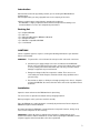
1
We would like to take this opportunity to thank you for selecting the DRC205 Room
Compensation.
We at Copland wish you many enjoyable hours in the company of fine music.
Please read this owners manual before operating the equipment.
The DRC205 is a highly complicated device that must be operated according to our
recommendations to secure safe and optimum performance.
1 pcs. Copland DRC205
1 pcs. AC-cord
1 pcs. Measuring Microphone (DRC205 calibrated)
1 pcs. Microphone Cable
1 pcs. Windows compatible CD-ROM
1 pcs. User Manual
!"
Various regulation agencies require us to bring the following information to your attention.
Please read carefully.
#
" "
To prevent fire or shock hazard, do not expose this unit to rain or moisture.
Check that your supply voltage is the same as indicated on the DRC205.
Do not connect the AC Power to the mains sockets if the voltage of the mains
is not as printed just below the AC Power inlet! This may cause fire hazard,
damage to equipment or personal hazard!
Dangerous voltage inside. Do not open the cabinet. There are no user
serviceable parts inside. Repairs should be carried out by qualified service
personnel only.
Ensure that no objects or fluids pass through openings in the chassis. If liquid is
spilt into the DRC205, disconnect from the mains and consult a qualified service
technician.
Open the carton and remove the DRC205 from its plastic bag.
The accessories are placed in the bottom of the packaging materials.
Before placing the unit in your home read this carefully.
Place the DRC205 on a stable platform in a normally dry environment. Do not subject the
DRC205 to high mechanical vibration.
By normal operation the DRC205 is operated from the front panel. However, during set-up
access to the rear-panel can be necessary.
$%
& When AC-power is applied for the first time or if AC-power has been
disconnected: Please wait for minimum 10 seconds before operating the DRC205, to allow
all power supplies and microcontrollers to become operational.
2
'
( ''
)'
To be acquainted with the DRC205, please read the following descriptions of the connections
on the unit and view the positions of connections below.
'
'
7
6
6
5
5
4
3
2
1
* ' & The AC power cord is plugged here.
The correct mains operating voltage is printed just below the mains inlet.
The DRC205 is supplied in either 110/120 Volt 50/60 Hz versions,
or 220/240 Volt 50/60 versions.
Only use a version compliant with your wall outlet voltage!
Do not connect the AC Power to the mains sockets if the voltage of the mains is
not as printed just below the AC Power inlet! This may cause fire hazard, damage
to equipment or personal hazard!
The DRC205 has very low power consumption and does thus not feature a power
switch! It is recommended to leave the unit turned on.
3
$% '
'
& IBM PC compatible USB port interface connector for
communication between a Windows 98/ME/2000/XP compatible PC/Computer
and the DRC205.
The connection can be used during set-up and calibration – or by advanced use of the
DRC205.
Connecting a PC/Computer with to the DRC205 is not required.
The Copland DRC205 can be operated as stand-alone unit without any external
usage of a PC/computer.
Advanced and professional users may prefer to set-up and calibrate the unit and the audio
system by help of an external Windows PC/computer. This increases the user flexibility of the
unit, but also makes set-up and calibration more complex.
If external PC/computer assisted operation is desired, then the [Computer] connection is only
necessary during set-up and calibration of the unit and the audio system.
Reduce the volume control on the amplifier (or pre-amplifier) during connection or
disconnection of the PC/computer! This provides optimum protection to our
loudspeakers.
The front-panel keys are DEACTIVATED when an external Windows compatible
PC/Computer controls the unit!
Connect the Windows PC/computers USB port to the [Computer] connection of the DRC205
before set-up and calibration of the unit and your audio system.
The computer does not need to be connected to the unit during normal playback
operation. However, the Windows compatible PC/computer can be used to control
the DRC205 if desired. (This is an advantage during manual set-up of P1 and P2
user programmes.)
Contact your dealer in case your PC/Computer is not Windows 98/ME/2000/XP compatible
and ask for potential updates of the DRC205 unit for support of non-compatible computers. (At
the closing of hereby User Manual only Windows compatible PC/Computers are supported by
the Copland DRC205.)
+ , )''
& The [High-Pass] selector corresponds to the Subsonic protection
filter indicators on the front panel.
The [High-Pass] selector is a 10-position rotary switch that must be preset according to the
audio system and loudspeakers used with the DRC205.
Important note: The [High-Pass] selector is ONLY active during set-up, calibration,
test and measurements! The setting has no negative impact upon the sonic
performance during playback. The function is designed only to protect your
loudspeakers during set-up, calibration, test and measurement!
[
] sets the high-pass filter (subsonic protection filter) at a cut-off of 16 Hz.
[Position 1] should ONLY be used in audio systems featuring large and rugged loudspeakers
capable of handling subsonic frequencies at FULL power!
It is recommended that [Position 1] is only used in audio systems featuring rugged 12”-15”
woofers or similar high-performance/high-power subwoofers and for laboratory measurement.
4
[
] sets the high-pass filter (subsonic protection filter) at a cut-off of 20 Hz.
[Position 2] should ONLY be used in audio systems featuring larger and rugged loudspeakers
capable of handling subsonic/bass frequencies at FULL power!
It is recommended that [Position 2] is only used in audio systems featuring rugged 8”-10”
woofers or similar high-performance/high-power subwoofers!
[
+] sets the high-pass filter (subsonic protection filter) at a cut-off of 32 Hz.
[Position 3] should be used in audio systems featuring high-quality floor standing fairly rugged
loudspeakers capable of handling bass frequencies at high power.
It is recommend that [Position 3] is used in audio systems featuring rugged 6”-8” woofers or
similar high-performance/high-power subwoofers!
[
.] sets the high-pass filter (subsonic protection filter) at a cut-off of 40 Hz.
[Position 4] should be used in audio systems featuring high-quality bookshelf or generalpurpose loudspeakers!
Copland recommends that [Position 4] is used in audio systems featuring small or generalpurpose woofers or similar standard subwoofers!
Important note: The [High-Pass] selector is set DEFAULT at [Position 3] !
Important note: Do NOT change the default setting to a lower value, unless you
are sure that your loudspeaker as minimum fulfils our recommendations!
Important note: Copland cannot be made liable for any damage to external
equipment used with the unit.
. /
%)
'
%
& 3.5mm Jack connector for the measuring microphone.
The Microphone connection is only used during set-up and calibration of the unit and the audio
system.
Connect the measuring microphone to the Microphone connection before set-up and
calibration of the unit and your audio system.
Disconnect the measuring microphone from the unit after set-up and calibration is done!
The microphone do not need to be connected to the unit during playback
operation. The microphone has no operational functions during playback.
Reduce the volume control on the amplifier (or pre-amplifier) during connection or
disconnection of the microphone! This provides optimum protection to our
loudspeakers.
Important note: The DRC205 is calibrated to the featured microphone!
The microphone are calibrated for optimum performance.
Important note: Do NOT connect an other microphone to the unit without running a
microphone calibration!
Important note: Do NOT connect any third-party microphone to the unit! The
microphone calibration will NOT work with third-party microphones!
5
& Read below.
%
0
%
& Read below.
The analog inputs and outputs of DRC205 supports cables with RCA connectors.
Connect the DRC205 to the TAPE MONITOR facility of your amplifier.
This will provide optimum flexibility in regard to operation of the unit.
Provided that your amplifier do not have a TAPE MONITOR connection, then you can connect
the DRC205 between your primary line signal source (e.g. a CD-Player) and your amplifier.
Highly recommended: Do not install the DRC205 between a pre-amplifier and poweramplifier (unless this is your only option for connecting the unit). The performance of a digital
processing unit like the DRC205 will be degraded by connection between pre-amplifiers and
power-amplifiers. Signal/Noise ratio will be impaired. Dynamic range will be impaired.
%
& Connect the DRC205 [Inputs] to the [Outputs] of the TAPE MONITOR connection
of your amplifier.
Alternative operation : If no TAPE MONITOR is available: Connect the DRC205 inputs to the
outputs of a line signal source (e.g. a CD-Player).
! %
& Connect the DRC205 [Outputs] to the [Inputs] of the TAPE MONITOR connection
of your amplifier.
Alternative operation : If no TAPE MONITOR is available: Connect the DRC205 outputs to a
line signal input of the amplifier (e.g. a CD-Player input ).
To minimise the introduction of hum and noise the shielded cables should run parallel to each
other or loosely twisted together. Locate the cables away from speaker leads and AC power
cords.
1
'
" $ 2' & Serial number information is important for future software upgrades!
Important note: Do NOT remove or damage the serial number. Missing serial
number may result in no possibility to perform future firmware upgrades of the unit!
6
3
'
The following description of the front panel may help you locating the operation features of
the unit.
Note that all functions are disabled on the front panel when the DRC205 is operated via a
Windows compatible PC/Computer!
1
2
3
4
''
'4 & By pressing this button, the unit will be switched between the 6 (six) different
playback programmes.
Each time the key is pressed the programme is switched cyclically between A1, A2, A3, A4, P1
and P2 programmes. Detailed information about the programmes can be found on following
sides of this user guide.
The [Select] key changes the tonal characteristic of the calibrated audio system
according to the programmes A1, A2, A3, A4, P1 and P2.
The [Select] key may be pressed upon desire during playback.
The [Select] key should not be activated during set-up and calibration! The [Select]
key is only for playback operation.
42
$
'
& LED indicator lamps will light when [Select] of A1, A2, A3,
A4, P1 or P2 is selected for playback mode.
Detailed information about the playback modes can be found on the following sides.
+
2
% '
5 '
& LED will light for the selected cut-off frequency for
the subsonic protection filters (controlled by the [High-Pass] key on the rear-panel of the unit).
The subsonic protection filter is only active during set-up and calibration of the unit.
See more details about the recommended settings of [High-Pass] key on rear-panel of the unit
below!
. ' % '4 & By pressing this button continuously for at least 3 (three) seconds, the
automatic set-up and calibration function of the unit is activated.
Do not press the [Setup] key during normal playback !
7
In case the [Setup] key is pressed indivertible, then a safety feature in the unit
avoid that test- and measurements is started unless the button is continuously
pressed for more than 3 (three) seconds.
42
$
' 6
(
( +( .7
Playback modes A1-A4 are predefined sound characteristics.
The playback modes determine the tonal balance of the compensated audio system.
& Pre-programmed playback mode A1 changes the overall sound characteristics to the
below frequency response. The basic characteristic of A1 is resulting in a flat linear frequency
response similar to the classic technical reference.
+ 20dB
+ 16dB
+ 12dB
TARGETCURVE - LINEAR RESPONSE (FLATRESPONSE)
+ 8dB
+ 4dB
0dB
-4dB
-8dB
-12dB
-16dB
-20dB
10Hz
50Hz
100Hz
500Hz
1kHz
5kHz
10kHz 20kHz
8
& Pre-programmed playback mode A2 changes the overall sound characteristics to the
below frequency response. The basic characteristics of A2 is that the acoustics energy in the
bass range which by nature is boosted by room reflections is re-created, however without the
room acoustics problems negative impact. To avoid the sound of the audio system being too
bright (and hereby “technical” rather than “musical”) a slight attenuation in higher mid-range
and lower high-range is applied. Controlled roll-off in the upper octave is applied.
A2 is advantageous to a very wide range of audio systems and is recommended
for users with personal preferences of “musical” sound characteristic rather than
“technical” sound characteristics.
+ 20dB
+ 16dB
+ 12dB
TARGETCURVE - BRITISH BROADCASTING COMPANY
+ 8dB
+ 4dB
0dB
-4dB
-8dB
-12dB
-16dB
-20dB
10Hz
50Hz
100Hz
500Hz
1kHz
5kHz
10kHz 20kHz
The A2 pre-programmed playback mode creates a sound characteristic very similar to the
preference of British Broadcast Company (BBC) in the higher frequency ranges and re-creates
a modest bass boost that improves the typical performance of most high-fidelity loudspeakers.
A2 may not be recommended for large loudspeakers capable of generating large
energy levels in the lowest octaves. A2 may not be recommended for very small
loudspeakers incapable of reproducing the lowest octaves with realistic energy
level (unless the loudspeakers limitations in regard to maximum sound pressure
level is fully respected).
9
+ & Pre-programmed playback mode A3 changes the overall sound characteristics to the
below frequency response. The basic characteristic of A3 is resulting in a linear frequency
response with a modest tilt. The tilt secures that the tonal balance after compensation is
natural. Many loudspeakers generate insufficient energy in the lower octaves as well as in the
important fundamental frequency range (Higher bass/lower mid-range), and at the same time
generate too much energy in the highest octaves. A3 creates a natural linear response after
compensation.
A3 is advantageous to a very wide range of audio systems and is recommended
for users with personal preferences of “musical” sound characteristic rather than
“technical” sound characteristics. A3 suits most classic designed high-fidelity
loudspeakers.
+ 20dB
+ 16dB
TARGETCURVE - CINEMA-STYLE LINEAR RESPONSE
+ 12dB
+ 8dB
+ 4dB
0dB
-4dB
-8dB
-12dB
-16dB
-20dB
10Hz
50Hz
100Hz
500Hz
1kHz
5kHz
10kHz 20kHz
A3 is especially advantageous to smaller loudspeakers – e.g. bookshelf
loudspeakers and medium size loudspeakers on stands.
A3 is furthermore advantageous in audio systems being used in movie systems.
A3 may not be recommended for large loudspeakers capable of generating large
energy levels in the lowest octaves. A3 may not be recommended for very small
loudspeakers incapable of reproducing the lowest octaves with realistic energy
level (unless the loudspeakers limitations in regard to maximum sound pressure
level is fully respected).
. & Pre-programmed playback mode A4 is as default set as talk-through (by-pass /
no compensation).
10
' % 42
$
' 6
(
7
Playback modes P1-P2 are user-defined sound characteristics.
On P1-P2 you can store your own playback modes for Copland DRC205. This means that you
may create your own specific playback mode according to your personal taste.
Default setting by delivery ex. Copland for P1-P2 is similar to A1 = Flat linear frequency
response similar to the classic technical reference.
User programming of P1-P2 requires an external Windows 98/ME/2000/XP
compatible PC/Computer being connected to the Copland DRC205!
P1-P2 can not be programmed without an external PC/Computer.
Programming your own playback modes for P1-P2 is described in “ Operating Copland
DRC205 from a PC/computer” .
!%'
5
%
When having correctly connected the Copland DRC205 to your audio system the basic
operation is as follows.
!%'
'- %
/ !
" "!
Connect the Copland DRC205 to the wall outlet and turn on the wall
outlet before any operation of the unit. This avoids any start-up noises that may be damaging
to your system!
#
" "
Do not operate the Copland DRC205 before the following basic set-up has been
carefully and correctly done.
The Copland DRC205 must be set-up to match your loudspeakers bass capability
– otherwise the automatic calibration procedure may cause damage to your
loudspeakers!
Before operating the Copland DRC205 the [High-Pass] selector on the rear panel must be
correctly set according to your loudspeakers!
, )''
& The [High-Pass] selector (See Rear panel # 3) must be set to match
your loudspeakers. See details and recommendations above in chapter Rear Panel!
Recommendation: If you are not sure about how to set the [High-Pass] selector or
not are sure about your loudspeakers low-frequency capabilities, then do not
change the default position of the [High-Pass] selector.
[High-Pass] selector set to [
] allow test-signals down to 16Hz to be emitted into
your loudspeakers! The subsonic protection indicator LED for 16Hz on the front panel lights up,
when [High-Pass] is set to [Position 1]. Do not use this setting unless you are sure that your
loudspeakers are capable of reproducing 16Hz test-signals without any risk of damaging the
loudspeakers!
11
[High-Pass] selector set to [
] allow test-signals down to 20Hz to be emitted into
your loudspeakers! The subsonic protection indicator LED for 20Hz on the front panel lights up,
when [High-Pass] is set to [Position 2]. Do not use this setting unless you are sure that your
loudspeakers are capable of reproducing 20Hz test-signals without any risk of damaging the
loudspeakers!
'5
'
& [High-Pass] selector set to (
+] allow test-signals down to 32Hz
to be emitted into your loudspeakers! The subsonic protection indicator LED for 32Hz on the
front panel lights up, when [High-Pass] is set to [Position 3].
)
' )' '5
'
*' 8
'
' 4
'
' ) 4
%' '
'
% 2 ' 5 '%
' 2' * + ,9 * )
4
5
$
)'
%' '
[High-Pass] selector set to [
.] allow test-signals down to 40Hz to be emitted into
your loudspeakers! The subsonic protection indicator LED for 40Hz on the front panel lights up,
when [High-Pass] is set to [Position 4]. Do not use this setting unless you are sure that your
loudspeakers are capable of reproducing test-signals at 40Hz without risk of damaging to your
loudspeakers!
$
4
2
%
'
'
Do not operate the Copland DRC205 before the above Operational Set-up has been done.
Read the following instructions carefully before starting the automatic room analysis and
calibration!
When having correctly connected the Copland DRC205 to your audio system and having
performed the Operational set-up, then the Copland DRC205 is ready for room acoustics
analysis and automatic systems calibration.
The following describe the analysis and calibration when operated directly from the front
panel of the Copland DRC205. ( For operation with an external PC/Computer – please refer to
“ Operating Copland DRC205 from a PC/computer” ).
' /
%) ' & Connect the featured measurement microphone to the Microphone
Input (See Rear panel # 4).
$ % 5' '
& Switch off all signal sources in your audio system! Select the TAPE
MONITOR as playback (if the Copland DRC205 is connected to a TAPE MONITOR loop as
recommended – otherwise select the source, the Copland DRC205 is connected to)!
Adjust the volume control on your amplifier (or pre-amplifier) to approx. 1:00-2:00 o’clock
position before starting the measurements. It is important to perform the measurements at a
sufficiently loud volume to avoid any non-desired noises (e.g. from traffic or other external
noise sources) influencing the measurements.
Important note: Do not change the volume on the amplifier (or pre-amplifier) during
the automatic room analysis and calibration procedure!
Explanation: The test signals of the Dynaton Digital Room Compensation (DDRC)
engine are designed to be as insensitive to background noise as technically
possible. However, it is recommended that you set the volume control at 1:00-2:00
o’clock position for best possible measurements and keep silent during the
measurement sequence.
12
The test signals automatically adjust to a suitable level (however maximum output
power is limited by your setting of the volume control on your amplifier. This is
heard as a series of clicking noises in the loudspeaker! Note that the room
analysis and calibration is done in sequence for each channel!
Explanation: The test signals analysing the room acoustics and the audio system
performance consists of a number of different noise-signals. Note that the lowfrequency test signals have larger acoustic output-levels than normally
experienced during playback of music
Explanation: During the room analysis and calibration process, the Copland
DRC205 signals the status of the process by flashing the LED’s on the front panel.
Detailed explanation follows where relevant.
Important note: Remember to turn the volume control of the amplifier (or preamplifier) back to your normally preferred volume after the measurements and
analysis is done!
$
4
& To start the automatic room analysis and calibration procedure
press the [Setup] key (See Front panel # 4) continuously for more than 3 seconds!
Explanation: If the [Setup] key is pressed for less than 3 seconds, the key does not
activate the room analysis and calibration procedure. This is done to avoid
in adverted start of the analysis and calibration during normal playback of music!
The [Setup] key is activated when the all the LED’s (See Front panel # 2 and # 3) starts to
flash simultaneously . The flashings indicate that the measurements will start in five seconds,
giving you time to take the microphone to the listening position.
/'
'$ '
% '5' '
'
%
& Hold the microphone as steady as
possible in your preferred listening position during the measurements adjusting the tonal
balance of your audio system.
It is recommended to hold the microphone in approx. the same height above the floor, as
your ears would be when listening to music!
The automatic analysis and calibration will start when the LED’s (See Front panel # 2 and # 3
are flashing individually in a running sequence (light starts from the left and moves to the right
on the front panel). The flashings indicate that the measurements are now in progress, and
that silence should be respected during the measurements to secure best possible results of
the acoustics analysis.
Test signals are now heard. The test signals may continue to be audible for up to approx. a
minute per channel. When no test signals are heard the (DDRC) engine is analysing and
calculating the required compensation method for your system. This may take up to approx. a
minute per channel. Please wait until the Copland DRC205 has performed the required internal
calculations.
Explanation: Note that the Copland DRC205 analyses each channel in sequence.
This means that all analysis is done for each channel before the next channel is
measured and analysed!
Explanation: When the analysis and calibration process is done, then the LED’s on
the front panel stops flashing! (The LED indicator for [High-Pass] setting
permanently lights up for 16Hz, 20Hz, 32Hz or 40Hz (depending upon setting) and
the LED indicator for playback mode A1, A2, A3, A4, P1, P2 permanently lights up
for the selected playback mode).
13
* 8
$'
$ % 5' & When the room analysis and calibration procedure is
done, please remember to turn down the volume control on the amplifier (or pre-amplifier).
' /
%) ' & When the room analysis and calibration is done, you can
disconnect the featured measurement microphone from the Microphone Input (See Rear
panel # 4). The microphone is not having any function during normal playback!
42
%'
When having correctly connected the Copland DRC205 to your audio system and having
performed the Room analysis and calibration procedure, then the Copland DRC205 is
ready for normal playback operation.
The following describe the playback operation when operated directly from the
front panel of the Copland DRC205.
$ % 5' '
& During normal playback with the Copland DRC205 the TAPE MONITOR
loop must be selected/active on your amplifier/pre-amplifier (if the Copland DRC205 is
connected to a TAPE MONITOR loop as recommended – otherwise select the source, the
Copland DRC205 is connected to)!
''
'4 & By pressing this button (See Front panel # 1), the unit will be switched between
the 6 (six) different playback programmes.
Each time the key is pressed the programme is switched cyclically between A1, A2, A3, A4, P1
and P2 programmes (The indicators on Front panel # 2 display the playback mode selected).
Select the desired playback programme and enjoy your audio system’s performance with room
compensation applied.
Explanation: The audio signal is muted for a moment when changing between A1,
A2, A3, A4, P1, P2.
Explanation: Upon demand you may change A1, A2, A3, A4, P1, P2 on the fly. All
playback parameters are automatically stored into the DDRC-Module inside the
Copland DRC205.
P1 and P2 are as default set like A1 = Flat linear frequency response similar to
technical reference.
User defined playback programmes may be loaded to P1-P2 via an external
PC/Computer.
- !/
8
'
%'
)' 5'
'
Included with the DRC205 is a graphical user interface, which can be installed from the
accompanying CD-ROM.
By installation on a standard Windows 98/ME/2000/XP compatible PC/computer, the DRC205
may be fully operated from the PC/computer and an advanced equalizer can be accessed,
allowing the user to adjust the frequency response of the system and to study the frequency
curves before and after compensation.
%
$'
':
9' & The name of the graphical user interface you will find on the
CD-ROM is “ Control panel ” this also works as a digital parametric equalizer that enables you
to tweak the performance of your Copland DRC205 and your audio system by changing the
“Target Curve”.
For operation of the parametric equalizer in the “Control panel ” on the CD-ROM, please refer
to the section in regard to “Operation via PC/computer”.
14
%
$$
& With the “Control panel” you can also design and test your personal
playback modes and store them in the playback modes for P1 and P2, please refer to the
section in regard to “Operation via PC/computer”.
%
' & The Copland DRC205 and the Dynaton Digital Room Compensation (DDRC)
engine is designed to support future updates and improvements.
Important note: The DDRC engine in Copland DRC205 is optimised to
requirements of Copland, and is different from standard Dynaton DDRC engines!
Upgrades should always be from Copland to secure full operation of the Copland
DRC205 after an upgrade!
5
; $%
'
5*
'
Before being able to operate the Copland DRC205 via a computer the software on the
following CD-ROM must be installed on a Windows 98/ME/2000/XP compatible PC/computer.
Connect the USB cable to the [Computer] connector on the rear panel of the Copland DRC205
and to a USB connector on your PC/computer.
Note: The software cannot install correctly if the USB cable is not connected
between the Copland DRC205 and the PC/computer.
Note: The software cannot install correctly if the power is switched off to the
Copland DRC205.
Insert the CD-ROM (that is supplied with the Copland DRC205) into the CD-ROM (or DVD)
drive on your computer.
The installation software automatically starts up and is ready for installation!
Note: If you have disabled AUTORUN on your CD-ROM/DVD drive, then you must
manually start the installation software by double-clicking the SETUP.EXE file on
the CD-ROM!
15
The software installation will reply with the following screen on your PC/computer monitor:
Select your preferred language on the menu!
Note: On this revision of the Copland DRC205 only ENGLISH language is available.
After having selected your preferred language, please press [Next >] on the above menu. The
following menu will appear on your PC/computer monitor.
To install the Copland DRC205 software – press [Next >].
To cancel the installation – press [Cancel].
16
If you choose to install the Copland DRC205 Windows XP software to your PC/computer, then
installation software suggests installing the software in C:\programs\DRC205 as default
software directory.
Note: If so desired, you may install the Copland DRC205 in another directory by
inputting the desired directory on the below screen.
Pres [Next >] to continue the installation process:
17
After having selected the destination for the installed software, the following screen appears
after pressing [Next >] to continue the installation process:
The installation software suggests setting up a program folder called “DRC205” which will
contain access to the Copland DRC205 software.
Note: If so desired, you may install the Copland DRC205 in another program
folder by inputting the desired folder name on the above screen.
After having selected a program folder – press [Next >] to continue the installation.
18
On the next screen the installation software suggests you setting up icon’s on your desk top for
quick access to the Copland DRC205 software on your PC/computer.
Please select [Yes] or [No] for setting up icon’s on your desktop.
Note: Quick Launch Toolbar is not available on present revision of the Copland
DRC205 installation software.
Click [Next >] to continue the software installation.
19
Now the installation is ready to copy files to your PC/computer, and the following screen is
displayed on your monitor.
Press [Next >] to copy and install the Copland DRC205 software on your PC/computer.
Press [Cancel] if you do not wish to copy and install the software.
After having pressed [Next >] the installation software automatically copy and install all
relevant files to your PC/computer. During the process a status bar will display the progress.
The installation may take several minutes.
20
When the installation is completed the following screen appears:
To confirm the installation has been completed – press [Finish] and the installation will be
completed.
To finalize and verify correct installation – open the “ Control panel 1.01 “ software either by
double-clicking the Copland Target Curve icon on your desktop or by selecting it in your
program launch menu.
The Copland DRC205 must be connected and operational! If the Copland
DRC205 is not connected to the PC/computer or is not powered up, the software
will display a warning of no connection to the Copland DRC205. Be sure that the
Copland DRC205 is connected and powered up.
The following screen appears when no connection is established between the Copland
DRC205 and the PC/computer.
$%
': The above warning also appears in case that the connection
was not successfully establishes between the Copland DRC205 and the
PC/computers COM-ports.
21
$%
': Normally the software automatically finds and checks your
PC/computer’s available COM-ports. However, if you are using other devices (e.g.
a MODEM) on a COM-port, this may cause the software automatic COM-port
identification to fail.
In case that your Copland DRC205 is correctly connected, powered up and the software is
installed and the above warning appears, then you should change COM-port settings on the
Copland Control panel software.
This is done by the roll-down menu on the upper right corner of the below screen.
COM-port roll-down menu
Connect
Change the COM-port setting to another available COM-port in the [COM-port roll-down
menu], if the Copland DRC205 is not automatically identified.
When connection is established, the Copland DRC205 is ready to be operated from the above
software screen.
You may force the Copland DRC205 and the PC/computer to connect by pressing
[CONNECT]. This may often be an advantage in case that the software does not automatically
identify the COM-port and automatically establish connection between Copland DRC205 and
the PC/computer.
22
3'
' * )'
%'
%
5 $
; $%
'
After installation of the Copland DRC205 Windows XP software, the unit may be fully operated
from a PC/computer.
Advanced features and functions are available when operating the Copland DRC205 from a
Windows compatible XP PC/computer.
Important note: Apart from the operation from the PC/computer, all other
instructions are the same when using the Copland DRC205 software. E.g.
microphone operation and handling is similar to operating the unit from the front
panel.
Important note: Refer to operation from front and rear panel for general
information in regard to basic operation!
On the below picture the functions of the Copland Control panel 1.0 software is presented and
explained.
1
10
2
11
3
12
4
5
6
7
13
8 9
14
! ;!55& By pressing this button, the Copland DRC205 software will toggle between
DRC On (Room Compensation On) and DRC Off (Room compensation Off – or Bypass).
23
3 ' 4%' & Roll-down menu for available filters for setting up a Target Curve (Tonal
balance characteristics for the Room Compensated stereo system).
Available functions are:
Bypass
Peaking
Shelf Low
Shelf High
Low pass
High pass
The filter is deactivated
Peaking filter is active
Shelving filter Low is active
Shelving filter High is active
Low pass filter is active
High pass filter is active
Note: The function of all filters (expect Bypass that deactivates the filter block) is
described in detail below!
+ 3 & Is the input box for the Frequency where a Filter type is set active.
Note: The function of all filters (expect Bypass that deactivates the filter block) is
described in detail below!
.
& Is the gain/attenuation slider (control) for each filter block. The function is similar to
the gain control of a classical equalizer. (However, the function of the Copland DRC205 is
significantly more sophisticated than a classical equalizer – even though the operation is just
as simple in regard to setting up a Target Curve for your stereo system.)
The gain may be adjusted between –6dB to +6dB.
The room compensation engine in Copland DRC205 has already optimised the
performance of your stereo system, so you should not attempt to increase the
GAIN in narrow frequency bands. Narrow band dips (notches) in the in-room
frequency response should not be compensated for, as this will introduce new
peaks in the frequency response that are dependent upon position. Furthermore
the human ear is insensitive to narrow band dips, so leave the narrow band dips
as they are. The Copland DRC205 has already optimised for best possible
performance!
The room compensation engine may already have used the maximum available
GAIN for the basic tonal balance optimisation. In case you attempt to GAIN the
same frequencies (that are already GAINED by the room compensation engine)
then you may risk overloading the Copland DRC205 resulting in increased
distortion of the source signal. Always use GAIN (+) with care and consideration!
(No restrictions apply to attenuation – negative gain – as attenuation do not cause
any risk of overloading the system.)
The Target Curve should only be used to create an overall tonal balance for your
stereo system – as the Copland room compensation engine does automatically
takes care of all other optimisation in both frequency and time domain.
< & Sets the bandwidth where the Fc of the Filter type is selected. Low value of Q (e.g.
below 1.0) results in a wide band effect of the Filter type – and high Q (e.g. above 1.0) results
in narrow band effect of the Filter type.
Recommendation: When using the Filtertype for generating a new Target Curve
for your stereo system, use low Q as this gives the best results both in terms of
audible effect and technical performance!
Do not use high Q as this generally is not required as the Copland room
compensation engine already have optimised the narrow band performance of
your stereo system, unless you wants to attenuate peaks at lower frequencies
(below 400 Hz)!
24
0
" & Pressing [SEND] will send the present setting of the Target Curve to the Copland
DRC205. Press send when you want to interactively listen to your Target Curve after having
made adjustments to the Filtertype etc.!
1
& Pressing [UPDATE] will update the present setting of the Target Curve to the
Copland DRC205 and update the software with information from the Copland DRC205.
=
& Available storage for personal Target Curves. Your own Target Curves may be
stores in the Copland DRC205 as P1 or P2. (A1-A4 is defined by Copland, and may also be
selected for playback from the Copland Target Curve 1.0 software when operated from a
PC/computer in the same way as P1-P2.)
Select P1 or P2 by clicking your mouse (or computer pointer device) on P1 or P2. When the
indicator box below the P1 or P2 is selected a black dot appears in the indicator box.
>
!
designed.
& Pressing [STORE] will update the P1 or P2 with the Target Curve that you have
After having pressed [STORE] the P1 and/or P2 Target Curves will be fully available for
playback – also without the PC/computer connected to the Copland DRC205.
3 ':; ? 5 $
& Displays the frequency in Hertz and the SPL (Sound Pressure
Level) in dB (decibel) at the point where you hold your mouse (or computer pointer device)
pointer.
The feature is an advantage when analysing the response of the stereo system.
%) 5 $
& Displays the identifiers for the following graphs that are available for
investigation and manual analysis of the stereo systems performance before and after applying
Copland DRC205 room compensation.
$%
': Unlike some other room compensation systems the Copland
DRC205 shows the genuine response of the stereo system both before and after
compensation! Some room compensation systems only display the graph before
compensation and the Target Curve, but no true information about the resulting
response after the compensation has been applied. All information’s are fully
available on Copland DRC205.
Available graphs are:
% 4
frequency.
Bi Quad
Room
DRC
DRC +Target
Target
Active filter being presently adjusted
Response before room compensation (L) + (R)
Genuine response after room compensation
Genuine response with DRC and Target Curve
Mathematical Target Curve (that is aimed for)
' & Displays the graphs as SPL (Sound Pressure Level) as function of
Note: By holding down the left mouse (or pointer device) button and dragging the
cursor towards the right direction over the graphs in the display area and the
release the left mouse (or pointer device) button, you may zoom-in on any detail of
the graphs. Zoom-out is done in the same way, but by moving the cursor in the left
direction (or by pressing the [Zoom-Out] button - #14).
$%
': Do not emphasize upon variances over narrow bands at
frequencies above 400 Hz and do not emphasize upon narrow band dips
anywhere in the response, as they are not causing any problems to the
performance of your stereo system!
+
4
& Pressing the [ANALYSIS] button will start a measurement and analysis of your
stereo system in the same way as if pressing [SET-UP] on the front panel.
25
$%
': Observe the same guidelines for measurement and analysis
as described for direct operation on the front panel of the Copland DRC205.
. @
$ -!
zoom (1:1).
& Pressing [Zoom-Out] button will reset the graphs in the Display area to default
!%'
%
5 $
; $%
'
All connections are similar to operation from the front panel, but the front panel buttons are
disabled when the Copland DRC205 is operated from the Copland Control panel 1.01
software.
'5 $
/'
'$ ' A
4
& Pressing the [ANALYSIS] button in the Copland
Target Curve 1.0 software starts the measurement and analysis.
During the measurement and analysis process a bar meter is displayed indicating that the
Copland DRC205 is performing measurements and analysis.
See front panel operation and respect the same precautions!
After the measurement and analysis, all graphs are available for your examination in the
Display Area of the Copland Control panel 1.01 software.
You may change the Target Curve and store your own preferred tonal balance in P1-P2,
hereby optimising your stereo system to your own personal preferences.
'
'*
'
8' & Please find here a short form guide for designing your own
Target Curves for P1 and P2.
This guide will provide some tips in regard to usage of the Target Curve filters (Filter types)
used to tweak the tonal balance of the stereo system.
Peaking Filter
The Peaking Filter has basically the same function as any parametric equalizer band. It is
hereby an advanced tonal control that can be used to attach the response at any frequency
with any bandwidth.
Important note: Respect the guidelines provided in the previous section for
optimum usage and results.
To use the Peaking Filter, select Peaking Filter in Filtertype.
Set the Fc (Attach frequency or centre frequency) of the Peaking Filter by inputting the desired
frequency into the Fc input box.
Select the Q (bandwidth) for the function of the Peaking Filter. Low Q (below 1.0) results in
filters affecting a wide frequency band – and high Q (above 1) results in filters affecting a
narrow frequency band.
Important note: If you do not have full technical understanding of the Q-factor for
filters, then you should not change the Q factor outside the 0,1-1.0 ranges.
Slide the [GAIN] until the desired SPL is obtained – either by gain (up to +6dB) or by
attenuation (up to –6dB).
#
" " : Be careful when applying gain to the system as this may result in
overloading of the Copland DRC205, overloading your amplifier and overloading
your loudspeaker. Copland has already increased insufficient SPL by the
automatic DDRC algorithm!
26
On the Bi Quad graph the resulting response of the Peaking Filter may be observed, and the
resulting Target Curve may be observed on the Target graph.
An example of a 1000 Hertz Peaking Filter with Q = 0.5 and Gain set at +5 dB can be seen
below:
Shelving Low Filter
The Shelving Low filter increases or decreases the SPL on lower frequencies (lower than Fc).
The Shelving filter is very well suited to change the balance between low frequencies and high
frequencies of the stereo system.
The Shelving filter is very well-suited to adjust the SPL of a loudspeaker driver unit that either
have too high SPL or too low SPL compared to the other loudspeaker driver units in the
loudspeaker system.
Important note: Respect the guidelines provided in the previous section for
optimum usage and results.
To use the Shelving Low filter, select Shelving Low in Filtertype.
Set the Fc (Attach frequency or centre frequency) of the Shelving Low by inputting the desired
frequency into the Fc input box.
Select the Q (bandwidth) for the function of the Shelving Low Filter. Low Q (below 1.0) results
in filters affecting a wide frequency band – and high Q (above 1) results in filters affecting a
narrow frequency band.
Important note: If you do not have full technical understanding of the Q-factor for
filters, then you should not change the Q factor outside the 0,1-1.0 ranges.
Slide the [GAIN] until the desired SPL is obtained – either by gain (up to +6dB) or by
attenuation (up to –6dB).
27
#
" " : Be careful when applying gain to the system as this may result in
overloading of the Copland DRC205, overloading your amplifier and overloading
your loudspeaker. Copland has already increased insufficient SPL by the
automatic DDRC algorithm!
On the Bi Quad graph the resulting response of the Shelving Low Filter may be observed,
and the resulting Target Curve may be observed on the Target graph.
An example of a 1000 Hertz Shelving Low Filter with Q = 0.5 and Gain set at +5 dB can be
seen below:
28
Shelving High Filter
The Shelving High filter increases or decreases the SPL on higher frequencies (higher than
Fc).
The Shelving High may be used instead of the Shelving Low to increase the bass level – by
decreasing the high range (treble) SPL. Hereby no risk of overloading your amplifier or
loudspeakers may occur. The only change required may be that the volume control of your
amplifier may have to be turned a little upwards to result in the desired SPL.
The Shelving High is similar to Shelving Low, but only changes higher frequencies SPL instead
of lower frequencies SPL.
An example of a 1000 Hertz Shelving High Filter with Q = 0.5 and Gain set at +5 dB can be
seen below:
29
Low pass Filter
The Low pass filter will roll-off frequencies above the selected Fc, and it used to limit the upper
frequency of a system.
Important note: Respect the guidelines provided in the previous section for
optimum usage and results.
To use the Low pass filter, select Low pass in Filtertype.
Set the Fc (Attach frequency or centre frequency) of the Shelving Low by inputting the desired
frequency into the Fc input box.
Select the Q (bandwidth), so the desired transfer function appears for Low pass Filter. Low Q
(below 0.7) results in filters with smooth roll-off – and high Q (above 0.7) results in filters that
overshoot. Generally lower Q’s have the best sounding performance – unless the filter is
applied where high-Q problems occurs – and the filter hereby counteracts the specific problem.
[GAIN] is disabled for Low pass filters.
On the Bi Quad graph the resulting response of the Low pass Filter may be observed, and
the resulting Target Curve may be observed on the Target graph.
An example of a 1000 Hertz Shelving Low Filter with Q = 0.5:
30
High pass Filter
The High pass filter will roll-off frequencies above the selected Fc, and it used to limit the lower
frequency of a system.
Otherwise similar to the Low pass filter.
An example of a 1000 Hertz Shelving High pass Filter with Q = 1.5:
31
Example of a Target Curve : All the available types of filters may be combined to design a
Target Curve filter.
Note: By combining different filters virtually any shape for the Target Curve may be
designed. There are no restrictions and disadvantages in the combination of
different Filter types.
Above: An example of a Target Curve made from 5 different filters.
Listening to Target Curves : When designing a Target Curve you can listen to the resulting
sound.
This may be done by pressing [SEND] after having changed a filter parameter.
Important note: In case audible distortion occurs after having pressed [SEND],
then change the settings back to a Target Curve where no distortion occurs.
Design tip: In case of distortion occurring – try to use attenuation of the
frequencies that a without problems and hereby decreasing the total output level.
Compensate for the reduced SPL by turning upwards on the volume control of
your amplifier instead!
Storing Target Curves to Copland DRC205 :
Target Curves can be stored by pressing [STORE] in the Control panel, hereby the target
curve is send to P1 when P1 is selected – or to P2 when P2 is selected.
32
%
%
'
5*
'
In case you wants to uninstall the Copland Control panel software, you must enter the directory
where the program files are stored (default is C:\programs\DRC205) and double-click the
UNINSTALL.EXE.
The following warning appears:
Press [Yes] for uninstalling all Copland DRC205 software from the PC/computer.
Press [No] to cancel uninstall.
In case uninstall has been selected the uninstall dialog box (see below) will occur showing the
status of the uninstall process. All parts of the software must be checked by the uninstall
process before the Copland Target Curve 1.0 software is removed from the PC/computer.
Press [OK] to finish the uninstall process.
33
%
)'
'
'
The Copland DRC205 and the internal Dynaton DDRC-Module can be updated with new
firmware via the Computer (See Rear panel # 2). This secures that you continuously are able
to have the latest Dynaton Digital Room Compensation engine installed in your Copland
DRC205 hereby enabling a long lifetime without the risk of having an obsolete product.
Important note: To perform firmware update of the Copland DRC205 and the
DDRC engine, you must have your serial number available, as the software is
copy-protected. (Your products serial number is located on the Rear panel # 7)
Important note: Your Copland DRC205 is loaded with the DDRC V2 dual-module
engine by delivery and does only work with dual-module compliant upgrades!
(Downloading a single-module revision of the DDRC engine will result in your
Copland DRC205 will not work properly.)
Important note: Information and software for future firmware updates will be made
public on the Copland web-site (copland.dk).
To run the upgrade software select DRC_205_UPDATE.EXE and run the software. Follow the
recommendations during the upgrade process.
The present software dialog box appears as follows:
Make sure that the COM-port is the correct one (must be the same as when the Copland
DRC205 is operated by a PC/computer).
34
First step is to check your present firmware revision – this is done by pressing [GET VERSION]
which reads the revision number of your firmware in your Copland DRC205.
#
" " : Upgrade only with valid software from Copland that is released and
approved for use. Otherwise the Copland DRC205 may be damaged during
software upgrades.
The dialog box displaying the text [VER] must return a firmware revision in BOTH boxes to be
valid for upgrade.
#
" " : Do NOT attempt to upgrade firmware if only one of the [VER]
indicates a revision number! The Copland DRC205 may be damaged during
software upgrades if only one [VER] number is displayed in above dialog box!
Both (2) [VER] MUST display a revision number for the firmware for valid
upgrading of the Copland DRC205.
Second step is to install the new firmware – this is done by pressing [UPGRADE].
#
" " : Always follow the instructions in the dialog box when updating the
firmware.
IMPORTANT : Always make sure that the power connection to the wall is switched
ON and that the power cord is securely attached both to the wall outlet as well as
the Copland DRC205. In case that the power is switched off during a firmware
update, the Copland DRC205 may suffer severe damage!
/
'
'
The DRC205 is built for a long lifetime, and no special care needs to be taken apart from what
is already described.
#
4
'8 '
Copland provides a warranty to the first purchaser for a period of one year that the
DRC205 will work perfectly. Copland usually commissions the Copland agency in the
country in which the DRC205 was purchased to carry out any warranty work.
Following consent from Copland in a particular case the warranty service may
also be claimed at an agency in another country.
Exemptions to the warranty are accessories, which can be supplied from your dealer in the
unfortunate situation that accessories are damaged.
If any accessories are defective by delivery, please contact your dealer immediately for
replacements.
35
%' 5
Frequency response
20Hz-20kHz
S/N ratio ( IHF-A curve )
Better than 100dB
Dynamic range
Better than 100dB
A/D converter
24 bit, 88,2kHz
D/A converter
24 bit, 88,2kHz
Compensation engine
Dynaton DDRC V2 engine (Dual Module Support)
PC Interface
USB
PC Operating System
Windows 98 / ME / 2000 / XP
Input Analogue
RCA : 2,4V RMS ( Factory set ).
Output Analogue
RCA : 2,4V RMS.
Microphone Input
3.5mm Jack (Calibrated to featured microphone)
Power consumption
7W
Nominal voltage
115V or 230V factory set for destination country only.
Mains voltage range
+/- 12%
Dimensions
430(W) 110(H) 390(D) mm.
Shipping weight
10 Kg.
DDRC Engine
Copland specific DDRC engine. Designed based upon Copland
Specifications for the Copland DRC205
(Some functions are different from the standard Dynaton
DDRC engine due to specific Copland requirements)
Jumpers for 2,0V and 3,0V
36