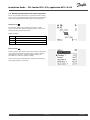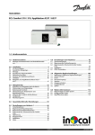
1
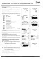
Installation Guide
ECL Comfort 210 / 310, application A214 / A314
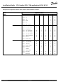
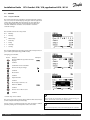
1.0 Table of Contents
1.0 Table of Contents ............................................... 1
6.0 Common controller settings............................ 123
1.1
6.1
6.2
6.3
6.4
6.5
6.6
6.7
6.8
Important safety and product information. . . . . . . . . . . . . . . . . . . . . 2
2.0 Installation ........................................................ 4
2.1
2.2
2.3
2.4
2.5
2.6
2.7
2.8
Before you start . . . . . . . . . . . . . . . . . . . . . . . . . . . . . . . . . . . . . . . . . . . . . . . . . . . . . 4
Identifying the system type . . . . . . . . . . . . . . . . . . . . . . . . . . . . . . . . . . . . . . 13
Mounting . . . . . . . . . . . . . . . . . . . . . . . . . . . . . . . . . . . . . . . . . . . . . . . . . . . . . . . . . . . 34
Placing the temperature sensors. . . . . . . . . . . . . . . . . . . . . . . . . . . . . . . . 37
Electrical connections. . . . . . . . . . . . . . . . . . . . . . . . . . . . . . . . . . . . . . . . . . . . . 39
Inserting the ECL Application Key . . . . . . . . . . . . . . . . . . . . . . . . . . . . . . 56
Check list . . . . . . . . . . . . . . . . . . . . . . . . . . . . . . . . . . . . . . . . . . . . . . . . . . . . . . . . . . . . 62
Navigation, ECL Application Key A214 / A314 . . . . . . . . . . . . . . . . 63
3.0 Daily use ......................................................... 73
3.1
3.2
3.3
3.4
3.5
3.6
3.7
Introduction to ‘Common controller settings’ . . . . . . . . . . . . . .
Time & Date. . . . . . . . . . . . . . . . . . . . . . . . . . . . . . . . . . . . . . . . . . . . . . . . . . . . . . .
Holiday . . . . . . . . . . . . . . . . . . . . . . . . . . . . . . . . . . . . . . . . . . . . . . . . . . . . . . . . . . . .
Input overview . . . . . . . . . . . . . . . . . . . . . . . . . . . . . . . . . . . . . . . . . . . . . . . . . . .
Log . . . . . . . . . . . . . . . . . . . . . . . . . . . . . . . . . . . . . . . . . . . . . . . . . . . . . . . . . . . . . . . . .
Output override. . . . . . . . . . . . . . . . . . . . . . . . . . . . . . . . . . . . . . . . . . . . . . . . . .
Key functions . . . . . . . . . . . . . . . . . . . . . . . . . . . . . . . . . . . . . . . . . . . . . . . . . . . . .
System . . . . . . . . . . . . . . . . . . . . . . . . . . . . . . . . . . . . . . . . . . . . . . . . . . . . . . . . . . . . .
123
124
125
127
128
129
130
131
7.0 Miscellaneous ................................................ 135
7.1
7.2
7.3
Several controllers in the same system . . . . . . . . . . . . . . . . . . . . . . 135
Frequently asked questions. . . . . . . . . . . . . . . . . . . . . . . . . . . . . . . . . . . . 137
Definitions . . . . . . . . . . . . . . . . . . . . . . . . . . . . . . . . . . . . . . . . . . . . . . . . . . . . . . . . 139
How to navigate . . . . . . . . . . . . . . . . . . . . . . . . . . . . . . . . . . . . . . . . . . . . . . . . . . . 73
Understanding the controller display . . . . . . . . . . . . . . . . . . . . . . . . . . 74
A general overview: What do the symbols mean? . . . . . . . . . . . 76
Monitoring temperatures and system
components . . . . . . . . . . . . . . . . . . . . . . . . . . . . . . . . . . . . . . . . . . . . . . . . . . . . . . . . 77
Influence overview . . . . . . . . . . . . . . . . . . . . . . . . . . . . . . . . . . . . . . . . . . . . . . . . 78
Manual control . . . . . . . . . . . . . . . . . . . . . . . . . . . . . . . . . . . . . . . . . . . . . . . . . . . . . 79
Schedule . . . . . . . . . . . . . . . . . . . . . . . . . . . . . . . . . . . . . . . . . . . . . . . . . . . . . . . . . . . . 80
4.0 Settings overview ............................................ 81
5.0 Settings, applications A214 / A314 .................... 84
5.1
5.2
5.3
5.4
5.5
5.6
5.7
5.8
5.9
5.10
5.11
5.12
Flow temperature. . . . . . . . . . . . . . . . . . . . . . . . . . . . . . . . . . . . . . . . . . . . . . . . . . 84
Room limit . . . . . . . . . . . . . . . . . . . . . . . . . . . . . . . . . . . . . . . . . . . . . . . . . . . . . . . . . . 86
Duct T limit. . . . . . . . . . . . . . . . . . . . . . . . . . . . . . . . . . . . . . . . . . . . . . . . . . . . . . . . . . 88
Return limit . . . . . . . . . . . . . . . . . . . . . . . . . . . . . . . . . . . . . . . . . . . . . . . . . . . . . . . . . 89
Limit T safety . . . . . . . . . . . . . . . . . . . . . . . . . . . . . . . . . . . . . . . . . . . . . . . . . . . . . . . 91
Compensation 1 . . . . . . . . . . . . . . . . . . . . . . . . . . . . . . . . . . . . . . . . . . . . . . . . . . . 92
Compensation 2 . . . . . . . . . . . . . . . . . . . . . . . . . . . . . . . . . . . . . . . . . . . . . . . . . . . 94
Control parameters (1) . . . . . . . . . . . . . . . . . . . . . . . . . . . . . . . . . . . . . . . . . . . . 97
Control parameters (2) . . . . . . . . . . . . . . . . . . . . . . . . . . . . . . . . . . . . . . . . . . 100
Fan / acc. control (fan / accessory control) . . . . . . . . . . . . . . . . . . 104
Application . . . . . . . . . . . . . . . . . . . . . . . . . . . . . . . . . . . . . . . . . . . . . . . . . . . . . . . 111
Alarm . . . . . . . . . . . . . . . . . . . . . . . . . . . . . . . . . . . . . . . . . . . . . . . . . . . . . . . . . . . . . . 119
Danfoss District Energy
VI.GU.A1.02
DEN-SMT/DK
1
Installation Guide
ECL Comfort 210 / 310, application A214 / A314
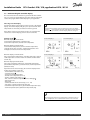
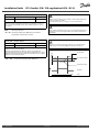
1.1 Important safety and product information
1.1.1 Important safety and product information
This Installation Guide is associated with ECL Application Key A214
(order code no. 087H3811).
The A214 Key contains two sets of applications:
one set (A214.1 / A214.2 / A214.3 / A214.4 / A214.5)
and another set (A314.1 / A314.2 / A314.3).
The functions can be realized in:
ECL Comfort 210 (A214) for simple solutions or
ECL Comfort 310 (A214 / A314) for advanced solutions, e.g. M-bus,
Modbus and Ethernet (Internet) communication.
A Remote Control Unit, ECA 30, can be connected and the built-in
room temperature sensor can be utilized.
The A314 applications demand the internal input / output module
ECA 32 for utilizing the analog output.
The applications A214 / A314 comply with ECL Comfort controllers
210 / 310 as of software version 1.36 (visible at start-up of the
controller and in ‘Common controller settings’ in ‘System’).
Additional documentation for ECL Comfort 210 and 310, modules
and accessories is available on http://den.danfoss.com/.
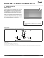
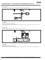
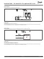
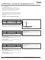
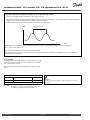
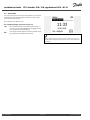
Automatic update of controller software:
The software of the controller is updated automatically when the key
is inserted (as of controller version 1.11). The following animation will
be shown when the software is being updated:
Progress bar
During update:
- Do not remove the KEY
- Do not disconnect the power
Safety Note
To avoid injury of persons and damages to the device, it is absolutely
necessary to read and observe these instructions carefully.
Necessary assembly, start-up, and maintenance work must be
performed by qualified and authorized personnel only.
The warning sign is used to emphasize special conditions that should
be taken into consideration.
2
DEN-SMT/DK
VI.GU.A1.02
Danfoss District Energy
Installation Guide
ECL Comfort 210 / 310, application A214 / A314
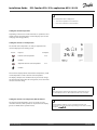
This symbol indicates that this particular piece of information should
be read with special attention.
As this Installation Guide covers several system types, special system
settings will be marked with a system type. All system types are shown
in the chapter: 'Identifying your system type'.
°C (degrees Celsius) is a measured temperature value whereas K
(Kelvin) is a number of degrees.
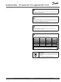
The ID no. is unique for the selected parameter.
Example
First digit
Second digit
Last three digits
11174
1
1
174
-
Circuit 1
Parameter no.
1
2
174
-
Circuit 2
Parameter no.
12174
If an ID description is mentioned more than once, it means that there
are special settings for one or more system types. It will be marked
with the system type in question (e.g. 12174 - A266.9).
Disposal Note
This product should be dismantled and its components
sorted, if possible, in various groups before recycling
or disposal.
Always follow the local disposal regulations.
Danfoss District Energy
VI.GU.A1.02
DEN-SMT/DK
3
Installation Guide
ECL Comfort 210 / 310, application A214 / A314
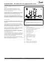
2.0 Installation
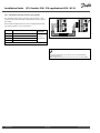
2.1 Before you start
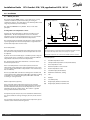
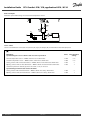
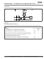
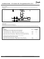
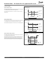
Typical A214.1 application:
S1
Da nfos s
87H2113.10
The Application Key A214 contains several applications, mainly
related to ventilation systems with heating or cooling or a
combination of these. The applications in the A214 key offer a wide
range of possibilities (see the examples).
ECL 210 / (310)
R4 (R6)
The application A214.1 is very flexible. These are the basic
principles:
M2
Cooling with room temperature control:
S5
Typically, the duct temperature is adjusted according to your
requirements. The duct temperature sensor S3 is the most
important sensor. The desired temperature at S3 is set in the ECL
Comfort controller as the 'Desired balance temperature'.
X3
P2
F1
S3
S4
The motorized control valve M2 (controlling the cooling transfer) is
opened gradually when the duct temperature is higher than the
desired duct temperature and vice versa.
Room temperature:
If the measured room temperature (S4 or ECA 30) does not equal
the desired room temperature, the desired temperature at S3 can
be adjusted.
By means of a week schedule (up to 3 ‘Comfort’ periods / day), the
cooling circuit can be in ‘Comfort’ or ‘Saving’ mode (two different
temperature values for desired room temperature).
The desired room temperature determines a correction of the
desired temperature at S3.
If the room temperature is not measured, the desired room
temperature equals (will be) the desired temperature at S3. In this
case, the setting of the 'Balance temperature' is not considered (or:
has no influence).
The shown diagram is a fundamental and simplified example and does
not contain all components that are necessary in a system.
All named components are connected to the ECL Comfort controller.
List of components:
S1
Outdoor temperature sensor
S2
Compensation temperature sensor (not illustrated)
S3
Duct temperature sensor
S4
Room temperature sensor / ECA 30
S5
Return temperature sensor
S8
Fire alarm input (not illustrated)
M2
Motorized control valve, cooling
F1
Fan
P2
Damper
X3
Circulation pump
Return temperature (optional):
R4
Relay output, alarm, ECL Comfort 210
If the measured return temperature (S5) does not equal the
limitation value (typically, the return temperature becomes lower
than the limitation value), the desired temperature at S3 can be
adjusted (typically to a higher value). This results in a gradual
closing of the motorized control valve.
(R6)
Relay output, alarm, ECL Comfort 310
The fan (F1) is ON / OFF controlled according to the schedule and
cooling demand. The damper (P2) is ON / OFF controlled according
to schedule. The circulation pump (X3) is ON / OFF controlled
according to cooling demand.
A simple frost protection (via S5) can be established. Furthermore,
it is expected that the cooling exchanger (fan coil) circuit contains
brine.
For a description of alarms and compensation temperature, please
read the section ‘A214 and A314 in general’.
4
DEN-SMT/DK
VI.GU.A1.02
Danfoss District Energy
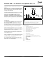
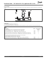
ECL Comfort 210 / 310, application A214 / A314
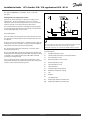
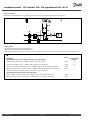
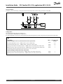
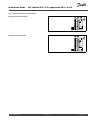
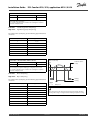
The application A214.2 is very flexible. These are the basic
principles:
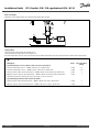
Typical A214.2 application:
S1
Heating with duct temperature control:
Da nfos s
87H2118.10
Installation Guide
ECL 210 / (310)
R4 (R6)
Typically, the heating temperature is adjusted according to
your requirements. The flow temperature sensor S3 is the most
important sensor. The desired temperature at S3 is set in the ECL
Comfort controller as the 'Desired balance temperature'.
M1
S3
The motorized control valve M1 (controlling the heating supply
temperature) is opened gradually when the flow temperature is
lower than the desired flow temperature and vice versa.
S5
X3
P2
F1
S4
S6
Duct temperature:
S7
If the measured duct temperature (S4) does not equal the desired
duct temperature, the desired temperature at S3 can be adjusted.
By means of a week schedule (up to 3 ‘Comfort’ periods / day),
the heating circuit can be in ‘Comfort’ or ‘Saving’ mode (two
different temperature values for desired duct temperature). The
desired duct temperature determines a correction of the desired
temperature at S3.
The fan (F1) is ON / OFF controlled according to the schedule and
heating demand. The damper (P2) is ON / OFF controlled according
to schedule. The circulation pump (X3) is ON / OFF controlled
according to heating demand.
For a description of alarms, compensation temperature, return
temperature limitation (S5) and frost protection (S6 and S7), please
read the section ‘A214 and A314 in general’.
Danfoss District Energy
The shown diagram is a fundamental and simplified example and does
not contain all components that are necessary in a system.
All named components are connected to the ECL Comfort controller.
List of components:
S1
Outdoor temperature sensor
S2
Compensation temperature sensor (not illustrated)
S3
Flow temperature sensor
S4
Duct temperature sensor
S5
Return temperature sensor
S6
Frost temperature sensor
S7
Frost thermostat
S8
Fire alarm input (not illustrated)
M1
Motorized control valve, heating
F1
Fan
P2
Damper
X3
Circulation pump
R4
Relay output, alarm, ECL Comfort 210
(R6)
Relay output, alarm, ECL Comfort 310
VI.GU.A1.02
DEN-SMT/DK
5
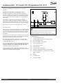
ECL Comfort 210 / 310, application A214 / A314
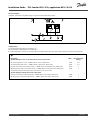
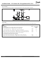
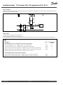
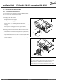
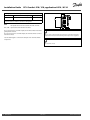
The application A214.3 is very flexible. These are the basic
principles:
Typical A214.3 application:
S1
Heating with room temperature control:
Da nfos s
87H2120.10
Installation Guide
ECL 210 / (310)
R4 (R6)
Typically, the duct temperature is adjusted according to your
requirements. The duct temperature sensor S3 is the most
important sensor. The desired temperature at S3 is set in the ECL
Comfort controller as the 'Desired balance temperature'.
M1
The motorized control valve M1 (controlling the heating supply)
is opened gradually when the duct temperature is lower than the
desired duct temperature and vice versa.
S5
X3
P2
F1
S3
S4
S6
Room temperature:
S7
If the measured room temperature (S4 or ECA 30) does not equal
the desired room temperature, the desired temperature at S3 can
be adjusted.
By means of a week schedule (up to 3 ‘Comfort’ periods / day), the
heating circuit can be in ‘Comfort’ or ‘Saving’ mode (two different
temperature values for desired room temperature).
All named components are connected to the ECL Comfort controller.
The desired room temperature determines a correction of the
desired temperature at S3.
The fan (F1) is ON / OFF controlled according to the schedule and
heating demand. The damper (P2) is ON / OFF controlled according
to schedule. The circulation pump (X3) is ON / OFF controlled
according to heating demand.
For a description of alarms, compensation temperature, return
temperature limitation (S5) and frost protection (S6 and S7), please
read the section ‘A214 and A314 in general’.
6
DEN-SMT/DK
The shown diagram is a fundamental and simplified example and does
not contain all components that are necessary in a system.
List of components:
S1
Outdoor temperature sensor
S2
Compensation temperature sensor (not illustrated)
S3
Duct temperature sensor
S4
Room temperature sensor / ECA 30
S5
Return temperature sensor
S6
Frost temperature sensor
S7
Frost thermostat
S8
Fire alarm input (not illustrated)
M1
Motorized control valve, heating
F1
Fan
P2
Damper
X3
Circulation pump
R4
Relay output, alarm, ECL Comfort 210
(R6)
Relay output, alarm, ECL Comfort 310
VI.GU.A1.02
Danfoss District Energy
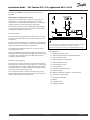
ECL Comfort 210 / 310, application A214 / A314
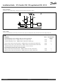
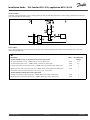
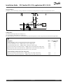
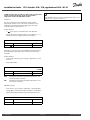
The application A214.4 is very flexible. These are the basic
principles:
Typical A214.4 application:
S1
Da nfos s
87H2122.10
Installation Guide
ECL 210 / (310)
Heating and cooling with duct temperature control:
R4 (R6)
Typically, the heating and cooling temperature is adjusted
according to your requirements.
M1
The flow temperature sensor S3 in the heating circuit is the most
important sensor. The desired temperature at S3 is set in the ECL
Comfort controller as the 'Desired balance temperature'.
S3
X3
M2
S5
P2
F1
The motorized control valve M1 (controlling the heating
temperature) is opened gradually when the flow temperature is
lower than the desired flow temperature and vice versa. At cooling,
the motorized control valve M2 controls the cooling temperature.
S4
S6
S7
Duct temperature:
A too low duct temperature (S4) will activate the heating circuit
(M1), whereas a too high duct temperature will activate the cooling
circuit (M2).
At heating demand, the duct temperature (S4) can adjust the
desired temperature at S3 when not being equal to the desired
duct temperature. At cooling demand, the duct temperature (S4) is
controlled according to the desired duct temperature.
By means of a week schedule (up to 3 ‘Comfort’ periods / day), the
heating circuit can be in ‘Comfort’ or ‘Saving’ mode (two different
temperature values for desired duct temperature).
The desired duct temperature determines a correction of the
desired temperature at S3 in heating mode. In cooling mode the
cooling is OFF during 'Saving'.
The fan (F1) is ON / OFF controlled according to the schedule and
heating / cooling demand. The damper (P2) is ON / OFF controlled
according to schedule. The circulation pump (X3) is ON / OFF
controlled according to heating demand.
For a description of alarms, compensation temperature, return
temperature limitation (S5) and frost protection (S6 and S7), please
read the section ‘A214 and A314 in general’.
Danfoss District Energy
The shown diagram is a fundamental and simplified example and does
not contain all components that are necessary in a system.
All named components are connected to the ECL Comfort controller.
List of components:
S1
Outdoor temperature sensor
S2
Compensation temperature sensor (not illustrated)
S3
Flow temperature sensor, heating circuit
S4
Duct temperature sensor
S5
Return temperature sensor
S6
Frost temperature sensor
S7
Frost thermostat
S8
Fire alarm input (not illustrated)
M1
Motorized control valve, heating
M2
Motorized control valve, cooling
F1
Fan
P2
Damper
X3
Circulation pump
R4
Relay output, alarm, ECL Comfort 210
(R6)
Relay output, alarm, ECL Comfort 310
VI.GU.A1.02
DEN-SMT/DK
7
ECL Comfort 210 / 310, application A214 / A314
The application A214.5 is very flexible. These are the basic
principles:
Typical A214.5 application:
S1
Da nfos s
87H2124.10
Installation Guide
ECL 210 / (310)
Heating and cooling with room temperature control:
R4 (R6)
Typically, the heating and cooling temperature in the duct is
adjusted according to your requirements. The duct temperature
sensor S3 is the most important sensor. The desired temperature
at S3 is set in the ECL Comfort controller as the 'Desired balance
temperature'.
M1
X3
M2
S5
P2
The motorized control valve M1 (controlling the heating
temperature) is opened gradually when the flow temperature is
lower than the desired flow temperature and vice versa. At cooling,
the motorized control valve M2 controls the cooling temperature.
F1
S3
S4
S6
S7
Room temperature:
If the measured room temperature (S4) does not equal the desired
room temperature, the desired temperature at S3 can be adjusted.
A too low room temperature will activate the heating circuit (M1),
whereas a too high room temperature will activate the cooling
circuit (M2).
By means of a week schedule (up to 3 ‘Comfort’ periods / day), the
heating circuit can be in ‘Comfort’ or ‘Saving’ mode (two different
temperature values for desired duct temperature).
All named components are connected to the ECL Comfort controller.
List of components:
The desired duct temperature determines a correction of the
desired temperature at S3 in heating mode. In cooling mode the
cooling is OFF during 'Saving'.
S1
Outdoor temperature sensor
S2
Compensation temperature sensor (not illustrated)
S3
Duct temperature sensor
The fan (F1) is ON / OFF controlled according to the schedule and
heating / cooling demand. The damper (P2) is ON / OFF controlled
according to schedule. The circulation pump (X3) is ON / OFF
controlled according to heating demand.
S4
Room temperature sensor / ECA 30
For a description of alarms, compensation temperature, return
temperature limitation (S5) and frost protection (S6 and S7), please
read the section ‘A214 and A314 in general’.
8
The shown diagram is a fundamental and simplified example and does
not contain all components that are necessary in a system.
DEN-SMT/DK
S5
Return temperature sensor
S6
Frost temperature sensor
S7
Frost thermostat
S8
Fire alarm input (not illustrated)
M1
Motorized control valve, heating
M2
Motorized control valve, cooling
F1
Fan
P2
Damper
X3
Circulation pump
R4
Relay output, alarm, ECL Comfort 210
(R6)
Relay output, alarm, ECL Comfort 310
VI.GU.A1.02
Danfoss District Energy
ECL Comfort 210 / 310, application A214 / A314
The application A314.1 is very flexible. These are the basic
principles:
Typical A314.1 application:
ECL 310 + ECA 32
S1
Heating and (passive) cooling with duct temperature control:
Da nfos s
87H2133.10
Installation Guide
R6
Typically, the heating and the cooling temperature is adjusted
according to your requirements.
M1
The flow temperature sensor S3 in the heating circuit is the most
important sensor. The desired temperature at S3 is set in the ECL
Comfort controller as the 'Desired balance temperature'.
S3
X3
P2
M2
S5
A
F1
The motorized control valve M1 (controlling the heating
temperature) is opened gradually when the flow temperature is
lower than the desired flow temperature and vice versa. At cooling,
the motorized control valve M2 controls the cooling temperature.
S4
S6
S7
The cooling section can be passive (re-circulation) or active.
Duct temperature:
A too low duct temperature (S4) will activate the heating circuit
(M1), whereas a too high duct temperature will activate the
(passive) cooling circuit (M2).
At heating demand, the duct temperature (S4) can adjust the
desired temperature at S3 when not being equal to the desired duct
temperature. At passive cooling demand, the duct temperature
(S4) is controlled according to the desired duct temperature.
The M1 is 3-point controlled, whereas the M2 is 0-10 V controlled.
By means of a week schedule (up to 3 ‘Comfort’ periods / day), the
heating circuit can be in ‘Comfort’ or ‘Saving’ mode (two different
temperature values for desired duct temperature).
The desired duct temperature determines a correction of the
desired temperature at S3 in heating mode. In cooling mode the
cooling is OFF during 'Saving'.
The fan (F1) is ON / OFF controlled according to the schedule and
heating / cooling demand. The damper (P2) is ON / OFF controlled
according to schedule. The circulation pump (X3) is ON / OFF
controlled according to heating demand.
For a description of alarms, compensation temperature, return
temperature limitation (S5) and frost protection (S6 and S7), please
read the section ‘A214 and A314 in general’.
Danfoss District Energy
The shown diagram is a fundamental and simplified example and does
not contain all components that are necessary in a system.
All named components are connected to the ECL Comfort controller.
List of components:
S1
Outdoor temperature sensor
S2
Compensation temperature sensor (not illustrated)
S3
Flow temperature sensor, heating circuit
S4
Duct temperature sensor
S5
Return temperature sensor
S6
Frost temperature sensor
S7
Frost thermostat
S8
Fire alarm input (not illustrated)
M1
Motorized control valve, heating, 3–point controlled
M2
F1
Motorized control valve, re-circulation / passive cooling,
0–10 V controlled
Fan
P2
Damper
X3
Circulation pump
R6
Relay output, alarm
VI.GU.A1.02
DEN-SMT/DK
9
ECL Comfort 210 / 310, application A214 / A314
The application A314.2 is very flexible. These are the basic
principles:
Typical A314.2 application:
S1
Heating and cooling with room temperature control:
Da nfos s
87H2127.10
Installation Guide
ECL 310 + ECA 32
R6
Typically, the heating and cooling temperature in the duct is
adjusted according to your requirements. The duct temperature
sensor S3 is the most important sensor. The desired temperature
at S3 is set in the ECL Comfort controller as the 'Desired balance
temperature'.
M1
S5
X3
The motorized control valve M1 (controlling the heating
temperature) is opened gradually when the flow temperature is
lower than the desired flow temperature and vice versa. At cooling,
the motorized control valve M2 controls the cooling temperature.
P2
M2
A
F1
S3
S4
S6
S7
The cooling section can be passive (re-circulation) or active.
Room temperature:
If the measured room temperature (S4) does not equal the desired
room temperature, the desired temperature at S3 can be adjusted.
A too low room temperature will activate the heating circuit (M1),
whereas a too high room temperature will activate the cooling
circuit (M2).
By means of a week schedule (up to 3 ‘Comfort’ periods / day), the
heating circuit can be in ‘Comfort’ or ‘Saving’ mode (two different
temperature values for desired duct temperature).
The desired duct temperature determines a correction of the
desired temperature at S3 in heating mode. In cooling mode the
cooling is OFF during 'Saving'.
The fan (F1) is ON / OFF controlled according to the schedule and
heating / cooling demand. The damper (P2) is ON / OFF controlled
according to schedule. The circulation pump (X3) is ON / OFF
controlled according to heating demand.
For a description of alarms, compensation temperature, return
temperature limitation (S5) and frost protection (S6 and S7), please
read the section ‘A214 and A314 in general’.
The shown diagram is a fundamental and simplified example and does
not contain all components that are necessary in a system.
All named components are connected to the ECL Comfort controller.
List of components:
S1
Outdoor temperature sensor
S2
Compensation temperature sensor (not illustrated)
S3
Duct temperature sensor
S4
Room temperature sensor / ECA 30
S5
Return temperature sensor
S6
Frost temperature sensor
S7
Frost thermostat
S8
Fire alarm input (not illustrated)
M1
Motorized control valve, heating, 3–point controlled
M2
Motorized control valve, re-circulation / passive cooling,
0–10 V controlled
Fan
F1
10
DEN-SMT/DK
P2
Damper
X3
Circulation pump
R6
Relay output, alarm
VI.GU.A1.02
Danfoss District Energy
ECL Comfort 210 / 310, application A214 / A314
The application A314.3 is very flexible. These are the basic
principles:
Typical A314.3 application:
S1
Heating with room temperature control:
Da nfos s
87H2131.10
Installation Guide
ECL 310 + ECA 32
R6
Typically, the duct temperature is adjusted according to your
requirements. The duct temperature sensor S3 is the most
important sensor. The desired temperature at S3 is set in the ECL
Comfort controller as the 'Desired balance temperature'.
M1
S10
The motorized control valve M1 (controlling the heating supply)
is opened gradually when the duct temperature is lower than the
desired duct temperature and vice versa.
S5
X3
P2
F1 / V1
S3
S4
S6
Room temperature:
S7
If the measured room temperature (S4 or ECA 30) does not equal
the desired room temperature, the desired temperature at S3 can
be adjusted.
By means of a week schedule (up to 3 ‘Comfort’ periods / day), the
heating circuit can be in ‘Comfort’ or ‘Saving’ mode (two different
temperature values for desired room temperature).
The shown diagram is a fundamental and simplified example and does
not contain all components that are necessary in a system.
All named components are connected to the ECL Comfort controller.
The desired room temperature determines a correction of the
desired temperature at S3.
The fan (F1) is ON / OFF controlled according to the schedule and
heating demand. The damper (P2) is ON / OFF controlled according
to schedule. The circulation pump (X3) is ON / OFF controlled
according to heating demand.
List of components:
S1 Outdoor temperature sensor
S2 Compensation temperature sensor (not illustrated)
S3 Duct temperature sensor
S4 Room temperature sensor / ECA 30
Variable fan speed (optional):
S5 Return temperature sensor
The fan (V1) can be speed controlled in relation to the measured
wind speed (S10). The fan speed control signal is a 0–10 volt signal,
generated by the internal input / output module ECA 32. A menu
in the ECL Comfort 310 contains settings for relationship between
actual wind speed and desired fan speed.
S6 Frost temperature sensor
S7 Frost thermostat
S8 Fire alarm input (not illustrated)
S10 Wind speed signal
For a description of alarms, compensation temperature, return
temperature limitation (S5) and frost protection (S6 and S7), please
read the section ‘A214 and A314 in general’.
M1 Motorized control valve, heating, 3–point controlled
V1 Fan speed, 0–10 V controlled
F1 Fan, ON / OFF controlled
P2 Damper
X3 Circulation pump
R6 Relay output, alarm
Danfoss District Energy
VI.GU.A1.02
DEN-SMT/DK
11
Installation Guide
ECL Comfort 210 / 310, application A214 / A314
A214 and A314 in general:
Compensation temperature (optional):
If the measured compensation temperature (S1 or S2) is higher or
lower than the limitation value, the desired temperature at S3 can
be adjusted. The compensation temperature can be measured
by the outdoor temperature sensor or for example an additional
room temperature sensor.
Override possibilities:
Unused input can, by means of an override switch, be used to
override the schedule to a fixed 'Comfort' or 'Saving' mode.
Alarm functions:
The alarm (relay 4 in ECL 210, relay 6 in ECL 310) is activated:
1. If an unaccepted deviation between the desired and actual S3
temperature occurs.
2. If a frost thermostat (S7) is activated.
3. If a frost temperature is detected at S5 or S6.
4. If the fire alarm (S8) is activated.
5. If a temperature sensor or its connection disconnects / short
circuits.
A214.2, A214.3, A214.4, A214.5, A314.1, A314.2 and A314.3:
Return temperature (optional):
If the measured return temperature (S5) does not equal the
limitation value (typically, the return temperature becomes higher
than the limitation value), the desired temperature at S3 can be
adjusted (typically to a lower value). This results in a gradual closing
of the motorized control valve.
Frost protection (optional):
Temperature sensor S6 and / or frost thermostat S7 can protect
the heat exchanger against frost.
Furthermore, if the S5 temperature becomes too low, it also can
enable the frost protection.
An activated frost protection will start the alarm, stop the fan F1,
close the damper P2 and fully open the motorized control valve M1.
Fire alarm (optional):
An activated fire alarm input will start the alarm, stop the fan F1,
close the damper P2 and close the motorized control valves.
The controller is pre-programmed with factory settings that are shown
in the relevant chapters of this guide.
12
DEN-SMT/DK
VI.GU.A1.02
Danfoss District Energy
Installation Guide
ECL Comfort 210 / 310, application A214 / A314
2.2 Identifying the system type
Sketch your application
The ECL Comfort controller series is designed for a wide range
of heating, domestic hot-water (DHW) and cooling systems with
different configurations and capacities. If your system differs
from the diagrams shown here, you may want to make a sketch
of the system about to be installed. This makes it easier to use
the Installation Guide, which will guide you step-by-step from
installation to final adjustments before the end-user takes over.
The ECL Comfort controller is a universal controller that can be
used for various systems. Based on the shown standard systems,
it is possible to configure additional systems. In this chapter you
find the most frequently used systems. If your system is not quite
as shown below, find the diagram which has the best resemblance
with your system and make your own combinations.
The circulation pump(s) in heating circuit(s) can be placed in the flow
as well as the return. Place the pump according to the manufacturer’s
specification.
S1
Da nfos s
87H2113.10
A214.1 example a
Ventilation system with cooling and constant room temperature control
ECL 210 / (310)
R4 (R6)
M2
S5
X3
P2
F1
S3
S4
Setting advice:
Set desired room temperature, for example 20 °C.
Set desired balance temperature, for example 12 °C.
If a room temperature sensor is not connected, the desired duct temperature at S3 will correspond to the desired room temperature.
Danfoss District Energy
VI.GU.A1.02
DEN-SMT/DK
13
Installation Guide
ECL Comfort 210 / 310, application A214 / A314
S1
Da nfos s
87H2114.10
A214.1 example b
Ventilation system with cooling and constant room temperature control. Chiller has constant flow.
ECL 210 / (310)
R4 (R6)
F1
S3
S4
S5
X3
M2
Setting advice:
Set desired room temperature, for example 20 °C.
Set desired balance temperature, for example 12 °C.
If a room temperature sensor is not connected, the desired duct temperature at S3 will correspond to the desired room temperature.
S1
Da nfos s
87H2115.10
A214.1 example c
Ventilation system (fan coils) with cooling and constant room temperature control
ECL 210 / (310)
R4 (R6)
F1
F1
S4
M2
S3
S5
X3
Setting advice:
Set desired room temperature, for example 5 °C.
Set desired balance temperature, for example 1 °C.
If a room temperature sensor is not connected, the desired flow temperature at S3 will correspond to the desired room temperature.
14
DEN-SMT/DK
VI.GU.A1.02
Danfoss District Energy
Installation Guide
ECL Comfort 210 / 310, application A214 / A314
S1
Da nfos s
87H2116.10
A214.1 example d
Cooling system with constant flow temperature control
ECL 210 / (310)
R4 (R6)
M2
S3
F1
Setting advice:
Set desired room temperature, for example 1 °C.
If a room temperature sensor is not connected, the desired flow temperature at S3 will correspond to the desired room temperature.
Set ‘Fan cut-in delay’ (ID no. 11086 — ‘Settings’, ‘Fan / acc. control’) to 0 seconds.
S1
Da nfos s
87H2117.10
A214.1 example e
Cooling system in ceiling and constant room temperature control in for example a wine cellar
ECL 210 / (310)
R4 (R6)
M2
S3
5 °C
S4
F1
Setting advice:
Set desired room temperature, for example 14 °C.
Set desired balance temperature, for example 10 °C.
If a room temperature sensor is not connected, the desired flow temperature at S3 will correspond to the desired room temperature.
Set ‘Fan cut-in delay’ (ID no. 11086 — ‘Settings’, ‘Fan / acc. control’) to 0 seconds.
Danfoss District Energy
VI.GU.A1.02
DEN-SMT/DK
15
Installation Guide
ECL Comfort 210 / 310, application A214 / A314
S1
Da nfos s
87H2118.10
A214.2 example a
Ventilation system with heating and constant duct temperature control
ECL 210 / (310)
R4 (R6)
M1
S3
S5
X3
P2
F1
S4
S6
S7
Sensor advice:
Sensor S3 and S4 must be connected. If not, the fan (F1) stops, the damper (P2) and motorized control valve (M1) close.
Navigation:
Special settings for sensors / thermostats used as frost protection:
ID no.: Recommended
setting:
S6* frost temperature sensor — MENU \ Alarm \ Frost T \ Alarm value
11676
5 °C
S5 return temperature sensor — MENU \ Alarm \ Limit T frost \ Alarm value
11656
5 °C
Closing contact of the S7* frost thermostat — MENU \ Alarm \ Frost thermostat \ Alarm value
11616
0
Opening contact of the S7* frost thermostat — MENU \ Alarm \ Frost thermostat \ Alarm value
11616
1
Closing contact of the S8 fire thermostat — MENU \ Alarm \ Fire safety \ Alarm value
11636
0
Opening contact of the S8 fire thermostat — MENU \ Alarm \ Fire safety \ Alarm value
11636
1
* both frost protection methods, by means of S6 and / or S7, can be used
Special settings for thermostats used as fire alarm:
16
DEN-SMT/DK
VI.GU.A1.02
Danfoss District Energy
Installation Guide
ECL Comfort 210 / 310, application A214 / A314
S1
ECL 210 / (310)
Da nfos s
87H2119.10
A214.2 example b
Heating of a swimming pool, constant water temperature control
R4 (R6)
S3
M1
S5
S4
F1
Sensor advice:
Sensor S3 and S4 must be connected. If not, the pump (F1) stops and motorized control valve (M1) closes.
Navigation:
Special settings for sensors / thermostats used as frost protection:
ID no.:
Recommended
setting:
S6* frost temperature sensor — MENU \ Alarm \ Frost T \ Alarm value
11676
5 °C
S5 return temperature sensor — MENU \ Alarm \ Limit T frost \ Alarm value
11656
5 °C
Closing contact of the S7* frost thermostat — MENU \ Alarm \ Frost thermostat \ Alarm value
11616
0
Opening contact of the S7* frost thermostat — MENU \ Alarm \ Frost thermostat \ Alarm value
11616
1
Closing contact of the S8 fire thermostat — MENU \ Alarm \ Fire safety \ Alarm value
11636
0
Opening contact of the S8 fire thermostat — MENU \ Alarm \ Fire safety \ Alarm value
11636
1
11086
0
* both frost protection methods, by means of S6 and / or S7, can be used
Special settings for thermostats used as fire alarm:
Other settings:
Fan cut-in delay — MENU \ Settings \ Fan / acc. control
Danfoss District Energy
VI.GU.A1.02
DEN-SMT/DK
17
Installation Guide
ECL Comfort 210 / 310, application A214 / A314
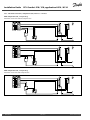
S1
Da nfos s
87H2120.10
A214.3 example a
Ventilation system with heating and constant room temperature control
ECL 210 / (310)
R4 (R6)
M1
S5
X3
P2
F1
S3
S4
S6
S7
Setting advice:
Set desired room temperature, for example 20 °C.
Set desired balance temperature, for example 20 °C.
If a room temperature sensor is not connected, the desired duct temperature at S3 will correspond to the desired room temperature.
Navigation:
Special settings for sensors / thermostats used as frost protection:
ID no.: Recommended
setting:
S6* frost temperature sensor — MENU \ Alarm \ Frost T \ Alarm value
11676
5 °C
S5 return temperature sensor — MENU \ Alarm \ Limit T frost \ Alarm value
11656
5 °C
Closing contact of the S7* frost thermostat — MENU \ Alarm \ Frost thermostat \ Alarm value
11616
0
Opening contact of the S7* frost thermostat — MENU \ Alarm \ Frost thermostat \ Alarm value
11616
1
Closing contact of the S8 fire thermostat — MENU \ Alarm \ Fire safety \ Alarm value
11636
0
Opening contact of the S8 fire thermostat — MENU \ Alarm \ Fire safety \ Alarm value
11636
1
* both frost protection methods, by means of S6 and / or S7, can be used
Special settings for thermostats used as fire alarm:
18
DEN-SMT/DK
VI.GU.A1.02
Danfoss District Energy
Installation Guide
ECL Comfort 210 / 310, application A214 / A314
S1
Da nfos s
87H2121.10
A214.3 example b
Ventilation system (fan coils) with heating and constant room temperature control
ECL 210 / (310)
R4 (R6)
F1
F1
S4
S3
X3
S5
M1
Setting advice:
Set desired room temperature, for example 20 °C.
Set desired balance temperature, for example 35 °C.
If a room temperature sensor is not connected, the desired flow temperature at S3 will correspond to the desired room temperature.
Navigation:
Special settings for sensors / thermostats used as frost protection:
ID no.: Recommended
setting:
S6* frost temperature sensor — MENU \ Alarm \ Frost T \ Alarm value
11676
5 °C
S5 return temperature sensor — MENU \ Alarm \ Limit T frost \ Alarm value
11656
5 °C
Closing contact of the S7* frost thermostat — MENU \ Alarm \ Frost thermostat \ Alarm value
11616
0
Opening contact of the S7* frost thermostat — MENU \ Alarm \ Frost thermostat \ Alarm value
11616
1
Closing contact of the S8 fire thermostat — MENU \ Alarm \ Fire safety \ Alarm value
11636
0
Opening contact of the S8 fire thermostat — MENU \ Alarm \ Fire safety \ Alarm value
11636
1
* both frost protection methods, by means of S6 and / or S7, can be used
Special settings for thermostats used as fire alarm:
Danfoss District Energy
VI.GU.A1.02
DEN-SMT/DK
19
Installation Guide
ECL Comfort 210 / 310, application A214 / A314
S1
Da nfos s
87H2122.10
A214.4 example a
Ventilation system with heating, cooling and constant duct temperature control
ECL 210 / (310)
R4 (R6)
M1
S3
X3
M2
S5
P2
F1
S4
S6
S7
Sensor advice:
Sensor S3 and S4 must be connected. If not, the fan (F1) stops, the damper (P2) and motorized control valves (M1 / M2) close.
Navigation:
Special settings for sensors / thermostats used as frost protection:
ID no.: Recommended
setting:
S6* frost temperature sensor — MENU \ Alarm \ Frost T \ Alarm value
11676
5 °C
S5 return temperature sensor — MENU \ Alarm \ Limit T frost \ Alarm value
11656
5 °C
Closing contact of the S7* frost thermostat — MENU \ Alarm \ Frost thermostat \ Alarm value
11616
0
Opening contact of the S7* frost thermostat — MENU \ Alarm \ Frost thermostat \ Alarm value
11616
1
Closing contact of the S8 fire thermostat — MENU \ Alarm \ Fire safety \ Alarm value
11636
0
Opening contact of the S8 fire thermostat — MENU \ Alarm \ Fire safety \ Alarm value
11636
1
* both frost protection methods, by means of S6 and / or S7, can be used
Special settings for thermostats used as fire alarm:
20
DEN-SMT/DK
VI.GU.A1.02
Danfoss District Energy
Installation Guide
ECL Comfort 210 / 310, application A214 / A314
S1
Da nfos s
87H2123.10
A214.4 example b
Ventilation system with heating, passive cooling (outside air) and constant duct temperature control
ECL 210 / (310)
R4 (R6)
M1
S3
S5
X3
P2
M2
F1
S4
S6
S7
Sensor advice:
Sensor S3 and S4 must be connected. If not, the fan (F1) stops, the damper (P2) and motorized control valves (M1 / M2) close.
Navigation:
Special settings for sensors / thermostats used as frost protection:
ID no.: Recommended
setting:
S6* frost temperature sensor — MENU \ Alarm \ Frost T \ Alarm value
11676
5 °C
S5 return temperature sensor — MENU \ Alarm \ Limit T frost \ Alarm value
11656
5 °C
Closing contact of the S7* frost thermostat — MENU \ Alarm \ Frost thermostat \ Alarm value
11616
0
Opening contact of the S7* frost thermostat — MENU \ Alarm \ Frost thermostat \ Alarm value
11616
1
Closing contact of the S8 fire thermostat — MENU \ Alarm \ Fire safety \ Alarm value
11636
0
Opening contact of the S8 fire thermostat — MENU \ Alarm \ Fire safety \ Alarm value
11636
1
* both frost protection methods, by means of S6 and / or S7, can be used
Special settings for thermostats used as fire alarm:
Danfoss District Energy
VI.GU.A1.02
DEN-SMT/DK
21
Installation Guide
ECL Comfort 210 / 310, application A214 / A314
S1
Da nfos s
87H2124.10
A214.5 example a
Ventilation system with heating, cooling and constant room temperature control
ECL 210 / (310)
R4 (R6)
M1
X3
M2
S5
P2
F1
S3
S4
S6
S7
Setting advice:
Set desired room temperature, for example 20 °C.
Set desired balance temperature, for example 20 °C.
If a room temperature sensor is not connected, the desired duct temperature at S3 will correspond to the desired room temperature.
Navigation:
Special settings for sensors / thermostats used as frost protection:
ID no.: Recommended
setting:
S6* frost temperature sensor — MENU \ Alarm \ Frost T \ Alarm value
11676
5 °C
S5 return temperature sensor — MENU \ Alarm \ Limit T frost \ Alarm value
11656
5 °C
Closing contact of the S7* frost thermostat — MENU \ Alarm \ Frost thermostat \ Alarm value
11616
0
Opening contact of the S7* frost thermostat — MENU \ Alarm \ Frost thermostat \ Alarm value
11616
1
Closing contact of the S8 fire thermostat — MENU \ Alarm \ Fire safety \ Alarm value
11636
0
Opening contact of the S8 fire thermostat — MENU \ Alarm \ Fire safety \ Alarm value
11636
1
* both frost protection methods, by means of S6 and / or S7, can be used
Special settings for thermostats used as fire alarm:
22
DEN-SMT/DK
VI.GU.A1.02
Danfoss District Energy
Installation Guide
ECL Comfort 210 / 310, application A214 / A314
S1
Da nfos s
87H2125.10
A214.5 example b
Ventilation system with heating, passive cooling (outside air) and constant room temperature control
ECL 210 / (310)
R4 (R6)
M1
S5
X3
P2
M2
F1
S3
S4
S6
S7
Setting advice:
Set desired room temperature, for example 20 °C.
Set desired balance temperature, for example 20 °C.
If a room temperature sensor is not connected, the desired duct temperature at S3 will correspond to the desired room temperature.
Navigation:
Special settings for sensors / thermostats used as frost protection:
ID no.: Recommended
setting:
S6* frost temperature sensor — MENU \ Alarm \ Frost T \ Alarm value
11676
5 °C
S5 return temperature sensor — MENU \ Alarm \ Limit T frost \ Alarm value
11656
5 °C
Closing contact of the S7* frost thermostat — MENU \ Alarm \ Frost thermostat \ Alarm value
11616
0
Opening contact of the S7* frost thermostat — MENU \ Alarm \ Frost thermostat \ Alarm value
11616
1
Closing contact of the S8 fire thermostat — MENU \ Alarm \ Fire safety \ Alarm value
11636
0
Opening contact of the S8 fire thermostat — MENU \ Alarm \ Fire safety \ Alarm value
11636
1
* both frost protection methods, by means of S6 and / or S7, can be used
Special settings for thermostats used as fire alarm:
Danfoss District Energy
VI.GU.A1.02
DEN-SMT/DK
23
Installation Guide
ECL Comfort 210 / 310, application A214 / A314
Da nfos s
87H2134.10
A214.5 example c
Ventilation system with heating, cross-flow heat exchanger control and constant room temperature control
ECL 210 / (310)
S1
R4 / (R6)
M1
S5
X3
P2
F1
S3
S4
S6
M2
S7
Setting advice:
Set desired room temperature, for example 20 °C.
Set desired balance temperature, for example 20 °C.
If a room temperature sensor is not connected, the desired duct temperature at S3 will correspond to the desired room temperature.
Navigation:
Special settings for sensors / thermostats used as frost protection:
ID no.: Recommended
setting:
S6* frost temperature sensor — MENU \ Alarm \ Frost T \ Alarm value
11676
5 °C
S5 return temperature sensor — MENU \ Alarm \ Limit T frost \ Alarm value
11656
5 °C
Closing contact of the S7* frost thermostat — MENU \ Alarm \ Frost thermostat \ Alarm value
11616
0
Opening contact of the S7* frost thermostat — MENU \ Alarm \ Frost thermostat \ Alarm value
11616
1
Closing contact of the S8 fire thermostat — MENU \ Alarm \ Fire safety \ Alarm value
11636
0
Opening contact of the S8 fire thermostat — MENU \ Alarm \ Fire safety \ Alarm value
11636
1
* both frost protection methods, by means of S6 and / or S7, can be used
Special settings for thermostats used as fire alarm:
24
DEN-SMT/DK
VI.GU.A1.02
Danfoss District Energy
Installation Guide
ECL Comfort 210 / 310, application A214 / A314
A314.1 example a
Ventilation system with heating, passive cooling (outside air) and constant duct temperature control. Analog controlled passive
cooling (M2).
Da nfos s
87H2133.10
ECL 310 + ECA 32
S1
R6
M1
S3
S5
X3
P2
M2
A
F1
S4
S6
S7
Sensor advice:
Sensor S3 and S4 must be connected. If not, the fan (F1) stops, the damper (P2) and motorized control valves (M1 / M2) close.
Navigation:
Special settings for sensors / thermostats used as frost protection:
ID no.: Recommended
setting:
S6* frost temperature sensor — MENU \ Alarm \ Frost T \ Alarm value
11676
5 °C
S5 return temperature sensor — MENU \ Alarm \ Limit T frost \ Alarm value
11656
5 °C
Closing contact of the S7* frost thermostat — MENU \ Alarm \ Frost thermostat \ Alarm value
11616
0
Opening contact of the S7* frost thermostat — MENU \ Alarm \ Frost thermostat \ Alarm value
11616
1
Closing contact of the S8 fire thermostat — MENU \ Alarm \ Fire safety \ Alarm value
11636
0
Opening contact of the S8 fire thermostat — MENU \ Alarm \ Fire safety \ Alarm value
11636
1
* both frost protection methods, by means of S6 and / or S7, can be used
Special settings for thermostats used as fire alarm:
Danfoss District Energy
VI.GU.A1.02
DEN-SMT/DK
25
Installation Guide
ECL Comfort 210 / 310, application A214 / A314
Da nfos s
87H2128.10
A314.1 example b
Ventilation system with heating, cooling and constant duct temperature control. Analog controlled cooling (M2).
ECL 310 + ECA 32
S1
R6
M1
M2
A
S3
X3
S5
P2
F1
S4
S6
S7
Sensor advice:
Sensor S3 and S4 must be connected. If not, the fan (F1) stops, the damper (P2) and motorized control valves (M1 / M2) close.
Navigation:
Special settings for sensors / thermostats used as frost protection:
ID no.: Recommended
setting:
S6* frost temperature sensor — MENU \ Alarm \ Frost T \ Alarm value
11676
5 °C
S5 return temperature sensor — MENU \ Alarm \ Limit T frost \ Alarm value
11656
5 °C
Closing contact of the S7* frost thermostat — MENU \ Alarm \ Frost thermostat \ Alarm value
11616
0
Opening contact of the S7* frost thermostat — MENU \ Alarm \ Frost thermostat \ Alarm value
11616
1
Closing contact of the S8 fire thermostat — MENU \ Alarm \ Fire safety \ Alarm value
11636
0
Opening contact of the S8 fire thermostat — MENU \ Alarm \ Fire safety \ Alarm value
11636
1
* both frost protection methods, by means of S6 and / or S7, can be used
Special settings for thermostats used as fire alarm:
26
DEN-SMT/DK
VI.GU.A1.02
Danfoss District Energy
Installation Guide
ECL Comfort 210 / 310, application A214 / A314
S1
Da nfos s
87H2126.10
A314.1 example c
Ventilation system with heating, passive cooling (outside air) and constant duct temperature control. Analog controlled speed of rotary
heat exchanger (M2) for heat recovery.
ECL 310 + ECA 32
R6
M1
S3
S5
X3
P2
F1
S4
S6
M2
S7
A
Sensor advice:
Sensor S3 and S4 must be connected. If not, the fan (F1) stops, the damper (P2) and motorized control valve (M1) close. The rotary
heat exchanger (M2) stops.
Navigation:
Special settings for sensors / thermostats used as frost protection:
ID no.: Recommended
setting:
S6* frost temperature sensor — MENU \ Alarm \ Frost T \ Alarm value
11676
5 °C
S5 return temperature sensor — MENU \ Alarm \ Limit T frost \ Alarm value
11656
5 °C
Closing contact of the S7* frost thermostat — MENU \ Alarm \ Frost thermostat \ Alarm value
11616
0
Opening contact of the S7* frost thermostat — MENU \ Alarm \ Frost thermostat \ Alarm value
11616
1
Closing contact of the S8 fire thermostat — MENU \ Alarm \ Fire safety \ Alarm value
11636
0
Opening contact of the S8 fire thermostat — MENU \ Alarm \ Fire safety \ Alarm value
11636
1
* both frost protection methods, by means of S6 and / or S7, can be used
Special settings for thermostats used as fire alarm:
Danfoss District Energy
VI.GU.A1.02
DEN-SMT/DK
27
Installation Guide
ECL Comfort 210 / 310, application A214 / A314
S1
Da nfos s
87H2127.10
A314.2 example a
Ventilation system with heating, passive cooling (outside air) and constant room temperature control. Analog controlled passive
cooling (M2).
ECL 310 + ECA 32
R6
M1
S5
X3
P2
M2
A
F1
S3
S4
S6
S7
Setting advice:
Set desired room temperature, for example 20 °C.
Set desired balance temperature, for example 20 °C.
If a room temperature sensor is not connected, the desired duct temperature at S3 will correspond to the desired room temperature.
Navigation:
Special settings for sensors / thermostats used as frost protection:
ID no.: Recommended
setting:
S6* frost temperature sensor — MENU \ Alarm \ Frost T \ Alarm value
11676
5 °C
S5 return temperature sensor — MENU \ Alarm \ Limit T frost \ Alarm value
11656
5 °C
Closing contact of the S7* frost thermostat — MENU \ Alarm \ Frost thermostat \ Alarm value
11616
0
Opening contact of the S7* frost thermostat — MENU \ Alarm \ Frost thermostat \ Alarm value
11616
1
Closing contact of the S8 fire thermostat — MENU \ Alarm \ Fire safety \ Alarm value
11636
0
Opening contact of the S8 fire thermostat — MENU \ Alarm \ Fire safety \ Alarm value
11636
1
* both frost protection methods, by means of S6 and / or S7, can be used
Special settings for thermostats used as fire alarm:
28
DEN-SMT/DK
VI.GU.A1.02
Danfoss District Energy
Installation Guide
ECL Comfort 210 / 310, application A214 / A314
Da nfos s
87H2135.10
A314.2 example b
Ventilation system with heating, cooling and constant room temperature control. Analog controlled cooling (M2).
ECL 310 + ECA 32
S1
R6
M1
M2
A
X3
S5
P2
F1
S3
S4
S6
S7
Setting advice:
Set desired room temperature, for example 20 °C.
Set desired balance temperature, for example 20 °C.
If a room temperature sensor is not connected, the desired duct temperature at S3 will correspond to the desired room temperature.
Navigation:
Special settings for sensors / thermostats used as frost protection:
ID no.: Recommended
setting:
S6* frost temperature sensor — MENU \ Alarm \ Frost T \ Alarm value
11676
5 °C
S5 return temperature sensor — MENU \ Alarm \ Limit T frost \ Alarm value
11656
5 °C
Closing contact of the S7* frost thermostat — MENU \ Alarm \ Frost thermostat \ Alarm value
11616
0
Opening contact of the S7* frost thermostat — MENU \ Alarm \ Frost thermostat \ Alarm value
11616
1
Closing contact of the S8 fire thermostat — MENU \ Alarm \ Fire safety \ Alarm value
11636
0
Opening contact of the S8 fire thermostat — MENU \ Alarm \ Fire safety \ Alarm value
11636
1
* both frost protection methods, by means of S6 and / or S7, can be used
Special settings for thermostats used as fire alarm:
Danfoss District Energy
VI.GU.A1.02
DEN-SMT/DK
29
Installation Guide
ECL Comfort 210 / 310, application A214 / A314
S1
Da nfos s
87H2129.10
A314.2 example c
Ventilation system with heating, passive cooling (outside air) and constant room temperature control. Analog controlled speed of rotary
heat exchanger (M2) for heat recovery.
ECL 310 + ECA 32
R6
M1
S5
X3
P2
F1
S3
S4
S6
M2
S7
A
Setting advice:
Set desired room temperature, for example 20 °C.
Set desired balance temperature, for example 20 °C.
If a room temperature sensor is not connected, the desired duct temperature at S3 will correspond to the desired room temperature.
Navigation:
Special settings for sensors / thermostats used as frost protection:
ID no.: Recommended
setting:
S6* frost temperature sensor — MENU \ Alarm \ Frost T \ Alarm value
11676
5 °C
S5 return temperature sensor — MENU \ Alarm \ Limit T frost \ Alarm value
11656
5 °C
Closing contact of the S7* frost thermostat — MENU \ Alarm \ Frost thermostat \ Alarm value
11616
0
Opening contact of the S7* frost thermostat — MENU \ Alarm \ Frost thermostat \ Alarm value
11616
1
Closing contact of the S8 fire thermostat — MENU \ Alarm \ Fire safety \ Alarm value
11636
0
Opening contact of the S8 fire thermostat — MENU \ Alarm \ Fire safety \ Alarm value
11636
1
* both frost protection methods, by means of S6 and / or S7, can be used
Special settings for thermostats used as fire alarm:
30
DEN-SMT/DK
VI.GU.A1.02
Danfoss District Energy
Installation Guide
ECL Comfort 210 / 310, application A214 / A314
Da nfos s
87H2130.10
A314.2 example d
Ventilation system with heating, analog controlled cross-flow heat exchanger (M2) and constant room temperature control
ECL 310 + ECA 32
S1
R6
M1
S5
X3
P2
F1
S3
S4
S6
M2
A
S7
Setting advice:
Set desired room temperature, for example 20 °C.
Set desired balance temperature, for example 20 °C.
If a room temperature sensor is not connected, the desired duct temperature at S3 will correspond to the desired room temperature.
Navigation:
Special settings for sensors / thermostats used as frost protection:
ID no.: Recommended
setting:
S6* frost temperature sensor — MENU \ Alarm \ Frost T \ Alarm value
11676
5 °C
S5 return temperature sensor — MENU \ Alarm \ Limit T frost \ Alarm value
11656
5 °C
Closing contact of the S7* frost thermostat — MENU \ Alarm \ Frost thermostat \ Alarm value
11616
0
Opening contact of the S7* frost thermostat — MENU \ Alarm \ Frost thermostat \ Alarm value
11616
1
Closing contact of the S8 fire thermostat — MENU \ Alarm \ Fire safety \ Alarm value
11636
0
Opening contact of the S8 fire thermostat — MENU \ Alarm \ Fire safety \ Alarm value
11636
1
* both frost protection methods, by means of S6 and / or S7, can be used
Special settings for thermostats used as fire alarm:
Danfoss District Energy
VI.GU.A1.02
DEN-SMT/DK
31
Installation Guide
ECL Comfort 210 / 310, application A214 / A314
S1
Da nfos s
87H2131.10
A314.3 example a
Ventilation system with heating and constant room temperature control. Analog controlled fan speed (V1) based on outdoor wind speed.
ECL 310 + ECA 32
R6
M1
S10
S5
X3
P2
F1 / V1
S3
S4
S6
S7
Setting advice:
Set desired room temperature, for example 20 °C.
Set desired balance temperature, for example 35 °C.
If a room temperature sensor is not connected, the desired duct temperature at S3 will correspond to the desired room temperature.
Navigation:
Special settings for sensors / thermostats used as frost protection:
ID no.: Recommended
setting:
S6* frost temperature sensor — MENU \ Alarm \ Frost T \ Alarm value
11676
5 °C
S5 return temperature sensor — MENU \ Alarm \ Limit T frost \ Alarm value
11656
5 °C
Closing contact of the S7* frost thermostat — MENU \ Alarm \ Frost thermostat \ Alarm value
11616
0
Opening contact of the S7* frost thermostat — MENU \ Alarm \ Frost thermostat \ Alarm value
11616
1
Closing contact of the S8 fire thermostat — MENU \ Alarm \ Fire safety \ Alarm value
11636
0
Opening contact of the S8 fire thermostat — MENU \ Alarm \ Fire safety \ Alarm value
11636
1
* both frost protection methods, by means of S6 and / or S7, can be used
Special settings for thermostats used as fire alarm:
32
DEN-SMT/DK
VI.GU.A1.02
Danfoss District Energy
Installation Guide
ECL Comfort 210 / 310, application A214 / A314
S1
Da nfos s
87H2132.10
A314.3 example b
Ventilation system with heating and constant room temperature control. Analog controlled air curtain (V1) speed based on outdoor wind
speed.
ECL 310 + ECA 32
R6
V1
A
M1
S10
S5
X3
P2
F1
S3
S4
S6
S7
Setting advice:
Set desired room temperature, for example 20 °C.
Set desired balance temperature, for example 35 °C.
If a room temperature sensor is not connected, the desired duct temperature at S3 will correspond to the desired room temperature.
Navigation:
Special settings for sensors / thermostats used as frost protection:
ID no.: Recommended
setting:
S6* frost temperature sensor — MENU \ Alarm \ Frost T \ Alarm value
11676
5 °C
S5 return temperature sensor — MENU \ Alarm \ Limit T frost \ Alarm value
11656
5 °C
Closing contact of the S7* frost thermostat — MENU \ Alarm \ Frost thermostat \ Alarm value
11616
0
Opening contact of the S7* frost thermostat — MENU \ Alarm \ Frost thermostat \ Alarm value
11616
1
Closing contact of the S8 fire thermostat — MENU \ Alarm \ Fire safety \ Alarm value
11636
0
Opening contact of the S8 fire thermostat — MENU \ Alarm \ Fire safety \ Alarm value
11636
1
* both frost protection methods, by means of S6 and / or S7, can be used
Special settings for thermostats used as fire alarm:
Danfoss District Energy
VI.GU.A1.02
DEN-SMT/DK
33
Installation Guide
ECL Comfort 210 / 310, application A214 / A314
2.3 Mounting
2.3.1 Mounting the ECL Comfort controller
For easy access, you should mount the ECL Comfort controller near
the system. Select one of the following methods using the same
base part (code no. 087H3220 (ECL Comfort 210) or 087H3230 (ECL
Comfort 310):
•
Mounting on a wall
•
Mounting on a DIN rail (35 mm)
The ECL Comfort 210 can be mounted in the ECL Comfort 210 /
310 base part.
The ECL Comfort 310 can only be mounted in the ECL Comfort
310 base part.
Screws, PG cable glands and rawlplugs are not supplied.
Locking the ECL Comfort controller
In order to fasten the ECL Comfort controller to its base part, secure
the controller with the locking pin.
To prevent injuries to persons or the controller, the controller has to
be securely locked into the base. For this purpose, press the locking
pin into the base until a click is heard and the controller no longer
can be removed from the base.
If the controller is not securely locked into the base part, there is a risk
that the controller during operation can unlock from the base and the
base with terminals (and also the 230 V a.c. connections) are exposed.
To prevent injuries to persons, always make sure that the controller
is securely locked into its base. If this is not the case, the controller
should not be operated!
The easy way to lock the controller to its base or unlock it is to use a
screw driver as lever.
34
DEN-SMT/DK
VI.GU.A1.02
Danfoss District Energy
Installation Guide
ECL Comfort 210 / 310, application A214 / A314
Mounting on a wall
Mount the base part on a wall with a smooth surface. Establish the
electrical connections and position the controller in the base part.
Secure the controller with the locking pin.
Mounting on a DIN rail (35 mm)
Mount the base part on a DIN rail. Establish the electrical
connections and position the controller in the base part. Secure
the controller with the locking pin.
Dismounting the ECL Comfort controller
In order to remove the controller from the base part, pull out the
locking pin by means of a screwdriver. The controller can now be
removed from the base part.
The easy way to lock the controller to its base or unlock it is to use a
screw driver as lever.
Before removing the ECL Comfort controller from the base part, ensure
that the supply voltage is disconnected.
Danfoss District Energy
VI.GU.A1.02
DEN-SMT/DK
35
Installation Guide
ECL Comfort 210 / 310, application A214 / A314
2.3.2 Mounting the Remote Control Units ECA 30/31
Select one of the following methods:
•
Mounting on a wall, ECA 30 / 31
•
Mounting in a panel, ECA 30
Screws and rawlplugs are not supplied.
Mounting on a wall
Mount the base part of the ECA 30 / 31 on a wall with a smooth
surface. Establish the electrical connections. Place the ECA 30 /
31 in the base part.
Mounting in a panel
Mount the ECA 30 in a panel using the ECA 30 frame kit (order code
no. 087H3236). Establish the electrical connections. Secure the
frame with the clamp. Place the ECA 30 in the base part. The ECA
30 can be connected to an external room temperature sensor.
The ECA 31 must not be mounted in a panel if the humidity
function is to be used.
36
DEN-SMT/DK
VI.GU.A1.02
Danfoss District Energy
Installation Guide
ECL Comfort 210 / 310, application A214 / A314
2.4 Placing the temperature sensors
2.4.1 Placing the temperature sensors
It is important that the sensors are mounted in the correct position
in your system.
The temperature sensor mentioned below are sensors used for
the ECL Comfort 210 and 310 series which not all will be needed
for your application!
Outdoor temperature sensor (ESMT)
The outdoor sensor should be mounted on that side of the building
where it is less likely to be exposed to direct sunshine. It should not
be placed close to doors, windows or air outlets.
Flow temperature sensor (ESMU, ESM-11 or ESMC)
Place the sensor max. 15 cm from the mixing point. In systems
with heat exchanger, Danfoss recommends that the ESMU-type to
be inserted into the exchanger flow outlet.
Make sure that the surface of the pipe is clean and even where
the sensor is mounted.
Return temperature sensor (ESMU, ESM-11 or ESMC)
The return temperature sensor should always be placed so that it
measures a representative return temperature.
Room temperature sensor (ESM-10, ECA 30 / 31 Remote Control
Unit)
Place the room sensor in the room where the temperature is to be
controlled. Do not place it on outside walls or close to radiators,
windows or doors.
Boiler temperature sensor (ESMU, ESM-11 or ESMC)
Place the sensor according to the boiler manufacturer’s
specification.
Air duct temperature sensor (ESMB-12 or ESMU types)
Place the sensor so that it measures a representative temperature.
ESM-11: Do not move the sensor after it has been fastened in order to
avoid damage to the sensor element.
DHW temperature sensor (ESMU or ESMB-12)
Place the DHW temperature sensor according to the manufacturer’s
specification.
Slab temperature sensor (ESMB-12)
Place the sensor in a protection tube in the slab.
Danfoss District Energy
VI.GU.A1.02
DEN-SMT/DK
37
Installation Guide
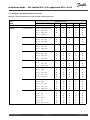
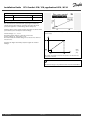
ECL Comfort 210 / 310, application A214 / A314
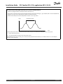
Pt 1000 temperature sensor (IEC 751B, 1000 Ω / 0 °C)
Relationship between temperature and ohmic value:
Ω
°C
Ω
-50
-40
-30
-20
-10
0
10
20
30
40
50
60
70
80
90
100
110
120
130
140
150
803
843
882
922
961
1000
1039
1078
1117
1155
1194
1232
1271
1309
1347
1385
1423
1461
1498
1535
1573
1600
1500
1400
1300
1200
1100
1000
900
800
°C
-50
38
DEN-SMT/DK
VI.GU.A1.02
-25
0
25
50
75
100
125
150
Danfoss District Energy
Installation Guide
ECL Comfort 210 / 310, application A214 / A314
2.5 Electrical connections
2.5.1 Electrical connections 230 V a.c. in general
The common ground terminal is used for connection of relevant
components (pumps, motorized control valves).
Danfoss District Energy
VI.GU.A1.02
DEN-SMT/DK
39
Installation Guide
ECL Comfort 210 / 310, application A214 / A314
2.5.2 Electrical connections, 230 V a.c., power supply, pumps, motorized control valves etc.
In general, the drawing and description below apply to all A214 applications.
However, please note that:
A214.1 is without M1
A214.2 / A214.3 are without M2
Terminal
16
15
14
Description
Max. load
Alarm
4 (2) A / 230 V a.c.*
Phase for control of connected units
13
X3
Circulation pump ON / OFF
4 (2) A / 230 V a.c.*
12
P2
Damper ON / OFF
4 (2) A / 230 V a.c.*
11
F1
Fan / pump ON / OFF
4 (2) A / 230 V a.c.*
10
Supply voltage 230 V a.c. - neutral (N)
9
Supply voltage 230 V a.c. - live (L)
8
M1
Phase for motorized control valve output
7
M1
Motorized control valve - opening
0.2 A / 230 V a.c.
6
M1
Motorized control valve - closing
0.2 A / 230 V a.c.
5
M2
Phase for motorized control valve output
4
M2
Motorized control valve - opening
0.2 A / 230 V a.c.
3
M2
Motorized control valve - closing
0.2 A / 230 V a.c.
* Relay contacts: 4 A for ohmic load, 2 A for inductive load
Factory established jumpers:
5 to 8, 9 to 14, L to 5 and L to 9, N to 10
Wire cross section: 0.5 - 1.5 mm²
Incorrect connection can damage the electronic outputs.
Max. 2 x 1.5 mm² wires can be inserted into each screw terminal.
40
DEN-SMT/DK
VI.GU.A1.02
Danfoss District Energy
Installation Guide
ECL Comfort 210 / 310, application A214 / A314
Da nfos s
87H2136.10
A314:
Terminal
19
18
R6
Description
Phase for alarm output
Max. load
Alarm
4 (2) A / 230 V a.c.*
17
Not to be used
16
Not to be used
15
14
Not to be used
Phase for control of connected units
13
X3
Circulation pump ON / OFF
4 (2) A / 230 V a.c.*
12
P2
Damper ON / OFF
4 (2) A / 230 V a.c.*
11
F1
Fan / pump ON / OFF
4 (2) A / 230 V a.c.*
10
Supply voltage 230 V a.c. - neutral (N)
9
Supply voltage 230 V a.c. - live (L)
8
M1
Phase for motorized control valve output
7
M1
Motorized control valve - opening
0.2 A / 230 V a.c.
6
M1
Motorized control valve - closing
0.2 A / 230 V a.c.
5
Not to be used
4
Not to be used
3
Not to be used
2
Not to be used
1
Not to be used
* Relay contacts: 4 A for ohmic load, 2 A for inductive load
Factory established jumpers:
5 to 8, 9 to 14, L to 5 and L to 9, N to 10
Wire cross section: 0.5 - 1.5 mm²
Incorrect connection can damage the electronic outputs.
Max. 2 x 1.5 mm² wires can be inserted into each screw terminal.
Danfoss District Energy
VI.GU.A1.02
DEN-SMT/DK
41
Installation Guide
ECL Comfort 210 / 310, application A214 / A314
2.5.3 Electrical connections, safety thermostats, 230 V a.c. or 24 V a.c.
Da nfos s
87H2105.10
With safety thermostat, 1–step closing:
Motorized control valve without safety function
ECL 210 / 310
Da nfos s
87H2106.10
M1
ECL 210 / 310
M2
Da nfos s
87H2107.10
With safety thermostat, 1–step closing:
Motorized control valve with safety function
ECL 210 / 310
M1
42
DEN-SMT/DK
VI.GU.A1.02
Danfoss District Energy
Installation Guide
ECL Comfort 210 / 310, application A214 / A314
Da nfos s
87H2108.10
ECL 210 / 310
M2
With safety thermostat, 2–step closing:
Motorized control valve with safety function
Da nfos s
87H2109.10
ECL 210 / 310
M1
Da nfos s
87H2110.10
ECL 210 / 310
M2
When ST is activated by a high temperature, the safety circuit in the
motorized control valve closes the valve immediately.
When ST1 is activated by a high temperature (the TR temperature), the
motorized control valve is closed gradually. At a higher temperature
(the ST temperature), the safety circuit in the motorized control valve
closes the valve immediately.
Danfoss District Energy
VI.GU.A1.02
DEN-SMT/DK
43
Installation Guide
ECL Comfort 210 / 310, application A214 / A314
Wire cross section: 0.5 - 1.5 mm²
Incorrect connection can damage the electronic outputs.
Max. 2 x 1.5 mm² wires can be inserted into each screw terminal.
44
DEN-SMT/DK
VI.GU.A1.02
Danfoss District Energy
Installation Guide
ECL Comfort 210 / 310, application A214 / A314
2.5.4 Electrical connections, 24 V a.c., power supply, pumps, motorized valves etc.
In general, the drawing and description below apply to all A214 applications.
However, please note that:
A214.1 is without M1
A214.2 / A214.3 are without M2
Terminal
16
15
14
Description
Max. load
Alarm
4 (2) A / 24 V a.c.*
Phase for control of connected units
13
R3 (K3)
Circulation pump ON / OFF
4 (2) A / 24 V a.c.*
12
R2 (K2)
Damper ON / OFF
4 (2) A / 24 V a.c.*
11
R1 (K1)
Fan / pump ON / OFF
4 (2) A / 24 V a.c.*
10
Supply voltage 24 V a.c. - (N)
9
Supply voltage 24 V a.c. - (L)
8
M1
Phase for motorized control valve output
7
M1
Motorized control valve - opening
1 A / 24 V a.c.
6
M1
Motorized control valve - closing
1 A / 24 V a.c.
5
M2
Phase for motorized control valve output
4
M2
Motorized control valve - opening
1 A / 24 V a.c.
3
M2
Motorized control valve - closing
1 A / 24 V a.c.
* Relay contacts: 4 A for ohmic load, 2 A for inductive load
Factory established jumpers:
5 to 8, 9 to 14, L to 5 and L to 9, N to 10
Wire cross section: 0.5 - 1.5 mm²
Incorrect connection can damage the electronic outputs.
Max. 2 x 1.5 mm² wires can be inserted into each screw terminal.
Danfoss District Energy
VI.GU.A1.02
DEN-SMT/DK
45
Installation Guide
ECL Comfort 210 / 310, application A214 / A314
Do not connect 230 V a.c. powered components to a 24 V a.c. power
supplied controller directly. Use auxilliary relays (K) to seperate 230
V a.c. from 24 V a.c.
46
DEN-SMT/DK
VI.GU.A1.02
Danfoss District Energy
Installation Guide
ECL Comfort 210 / 310, application A214 / A314
Da nfos s
87H2137.10
A314:
Terminal
19
18
R6
Description
Phase for alarm output
Max. load
Alarm
4 (2) A / 24 V a.c.*
17
Not to be used
16
Not to be used
15
14
Not to be used
Phase for control of connected units
13
R3 (K3)
Circulation pump ON / OFF
4 (2) A / 24 V a.c.*
12
R2 (K2)
Damper ON / OFF
4 (2) A / 24 V a.c.*
11
R1 (K1)
Fan / pump ON / OFF
4 (2) A / 24 V a.c.*
10
Supply voltage 24 V a.c. - (N)
9
Supply voltage 24 V a.c. - (L)
8
M1
Phase for motorized control valve output
7
M1
Motorized control valve - opening
1 A / 24 V a.c.
6
M1
Motorized control valve - closing
1 A / 24 V a.c.
5
Not to be used
4
Not to be used
3
Not to be used
2
Not to be used
1
Not to be used
* Relay contacts: 4 A for ohmic load, 2 A for inductive load
Factory established jumpers:
5 to 8, 9 to 14, L to 5 and L to 9, N to 10
Wire cross section: 0.5 - 1.5 mm²
Incorrect connection can damage the electronic outputs.
Max. 2 x 1.5 mm² wires can be inserted into each screw terminal.
Danfoss District Energy
VI.GU.A1.02
DEN-SMT/DK
47
Installation Guide
ECL Comfort 210 / 310, application A214 / A314
Do not connect 230 V a.c. powered components to a 24 V a.c. power
supplied controller directly. Use auxilliary relays (K) to seperate 230
V a.c. from 24 V a.c.
48
DEN-SMT/DK
VI.GU.A1.02
Danfoss District Energy
Installation Guide
ECL Comfort 210 / 310, application A214 / A314
A314— ECA 32:
Double-insulated (two-chamber) transformer
Terminal
Description
Max. load
49
Common terminal (connected to terminal 30 in the ECL Comfort controller)
56
Analog reference for Analog Out 2 and 3
57
Not to be used
58
Not to be used
59 M2
Analog Out 1
60
Analog Out 2 (not used)
61
62
Analog Out 3 (not used)
47 kΩ*
Analog reference for Analog Out 1
* The value must be 47 kΩ as a minimum.
Wire cross section: 0.5 - 1.5 mm²
Incorrect connection can damage the electronic outputs.
Max. 2 x 1.5 mm² wires can be inserted into each screw terminal.
Do not connect 230 V a.c. powered components to a 24 V a.c. power
supplied controller directly. Use auxilliary relays (K) to seperate 230
V a.c. from 24 V a.c.
Danfoss District Energy
VI.GU.A1.02
DEN-SMT/DK
49
Installation Guide
ECL Comfort 210 / 310, application A214 / A314
2.5.5 Electrical connections, Pt 1000 temperature sensors and signals
A214/ A314:
Terminal
Sensor / description
29 and 30 S1
28 and 30 S2
27 and 30 S3
26 and 30 S4
25 and 30 S5
24 and 30 S6
23 and 30 S7
22 and 30 S8
21 and 30
20 and 30
Type
(recomm.)
ESMT
Outdoor temperature
sensor*
Compensation temperature ESM-11 / ESMB /
sensor**
ESMC / ESMU /
ESMT
ESM-11 / ESMB /
Duct / flow temperature
ESMC / ESMU
sensor***
Room temperature sensor
ESM-11 / ESMB /
(A214.1 / A214.3 / A214.5 / ESMC / ESMU
A314.2 / A314.3)
Duct temperature sensor
(A214.2 / A214.4 / A314.1)
Return temperature sensor ESM-11 / ESMB /
ESMC / ESMU
Frost temperature sensor
**** (not in A214.1)
Frost thermostat *****
Fire thermostat ***** (fire
alarm)
ECL 310 only:
Not used
ECL 310 only:
Wind speed sensor (only in
A314.3)
*
If the outdoor temperature sensor is not connected or the
cable is short-circuited, the controller assumes that the
outdoor temperature is 0 (zero) °C.
**
Could for example be an extra room temperature sensor.
***
If the sensor is not connected or the cable is short-circuited,
the motorized control valve closes (safety function).
**** Both frost protection methods can be used.
***** Can be set up to react on a closing or an opening contact.
Factory established jumper:
30 to common terminal.
50
DEN-SMT/DK
VI.GU.A1.02
Danfoss District Energy
Installation Guide
ECL Comfort 210 / 310, application A214 / A314
Connection of frost thermostats, S7
When frost (too low temperature) is detected, contacts 1-2 close.
When frost (too low temperature) is detected, contacts 1-4 open.
Connection of fire thermostats, S8
When fire (too high temperature) is detected, the contacts 1-4
close.
When fire (too high temperature) is detected, the contacts 1-2
open.
Danfoss District Energy
VI.GU.A1.02
DEN-SMT/DK
51
Installation Guide
ECL Comfort 210 / 310, application A214 / A314
Wire cross section for sensor connections: Min. 0.4 mm².
Total cable length: Max. 200 m (all sensors incl. internal ECL 485
communication bus)
Cable lengths of more than 200 m may cause noise sensibility (EMC).
52
DEN-SMT/DK
VI.GU.A1.02
Danfoss District Energy
Installation Guide
ECL Comfort 210 / 310, application A214 / A314
Terminal Terminal
ECL
ECA 30 / 31
4
30
31
1
32
2
33
3
4
5
Description
Type
(recomm.)
ECA 30 / 31
ECL 210 / 310
Da nfos s
87H2051.10
2.5.6 Electrical connections, ECA 30 / 31
Twisted pair
Cable 2 x
twisted pair
Twisted pair
Ext. room temperature
sensor*
B
ESM-10
A
B
ESM-10
* After an external room temperature sensor has been connected,
ECA 30 / 31 must be repowered.
A
The communication to the ECA 30 / 31 must be set up in the ECL
Comfort controller in 'ECA addr.'
The ECA 30 /31 must be set up accordingly.
After application setup the ECA 30 / 31 is ready after 2–5 min. A
progress bar in the ECA 30 / 31 is displayed.
ECA information message:
‘Application req. newer ECA’:
The software of your ECA does not comply with the software of your
ECL Comfort controller. Please contact your Danfoss sales office.
Some applications do not contain functions related to actual room
temperature. The connected ECA 30 / 31 will only function as remote
control.
Total cable length: Max. 200 m (all sensors incl. internal ECL 485
communication bus).
Cable lengths of more than 200 m may cause noise sensibility (EMC).
Danfoss District Energy
VI.GU.A1.02
DEN-SMT/DK
53
Installation Guide
ECL Comfort 210 / 310, application A214 / A314
2.5.7 Electrical connections, master / slave systems
Da nfos s
87H2052.10
The controller can be used as master or slave in master / slave
systems via the internal ECL 485 communication bus (2 x twisted
pair cable).
The ECL 485 communication bus is not compatible with the ECL
bus in ECL Comfort 110, 200, 300 and 301!
Terminal Description
30
Common terminal
31*
+12 V*, ECL 485 communication bus
32
A, ECL 485 communication bus
33
B, ECL 485 communication bus
Type
(recomm.)
B
B
A
A
B
B
A
A
Cable 2 x
twisted pair
* Only for ECA 30 / 31 and master / slave communication
Total cable length: Max. 200 m (all sensors incl. internal ECL 485
communication bus).
Cable lengths of more than 200 m may cause noise sensibility (EMC).
54
DEN-SMT/DK
VI.GU.A1.02
Danfoss District Energy
Installation Guide
ECL Comfort 210 / 310, application A214 / A314
Electrical connections, Modbus
ECL 210 / 310
Da nfos s
87H2060.10
2.5.8 Electrical connections, communication
B
A
B
Electrical connections, M-bus
Da nfos s
87H2061.10
A
ECL 310
B
A
B
A
Danfoss District Energy
VI.GU.A1.02
DEN-SMT/DK
55
Installation Guide
ECL Comfort 210 / 310, application A214 / A314
2.6 Inserting the ECL Application Key
2.6.1 Inserting the ECL Application Key
This section describes the function in general for the ECL Comfort
210 / 310 series and is not application related.
The ECL Application Key contains
•
the application and its subtypes,
•
currently available languages,
•
factory settings: e.g. schedules, desired temperatures,
limitation values etc. It is always possible to recover the factory
settings,
•
memory for user settings: special user / system settings.
After having powered-up the controller, different situations might
be existing:
1. The controller is new from the factory, the ECL Application Key
is not inserted.
2. The controller already runs an application. The ECL Application
Key is inserted, but the application needs to be changed.
3. A copy of the controllers settings is needed for configuring
another controller.
User settings are, among others, desired room temperature, desired
DHW temperature, schedules, heat curve, limitation values etc.
System settings are, among others, communication set-up, display
brightness etc.
56
DEN-SMT/DK
VI.GU.A1.02
Danfoss District Energy
Installation Guide
ECL Comfort 210 / 310, application A214 / A314
Automatic update of controller software:
The software of the controller is updated automatically when the key
is inserted (as of controller version 1.11). The following animation will
be shown when the software is being updated:
Progress bar
During update:
- Do not remove the KEY
- Do not disconnect the power
Danfoss District Energy
VI.GU.A1.02
DEN-SMT/DK
57
Installation Guide
ECL Comfort 210 / 310, application A214 / A314
Application Key: Situation 1
The controller is new from the factory, the ECL Application Key
is not inserted.
An animation for the ECL Application Key insertion is displayed.
Insert the Application Key .
Application Key name and Version is indicated (example: A266
Ver. 1.03).
If the ECL Application Key is not suitable for the controller, a "cross"
is displayed over the ECL Application Key-symbol.
Action:
Purpose:
Examples:
Select language
Confirm
Select application
Confirm with ‘Yes’
Set 'Time & Date'
Turn and push the dial to select and
change 'Hours', 'Minutes', 'Date',
'Month' and 'Year'.
Choose ''Next'
Confirm with ‘Yes’
Go to ‘Aut. daylight’
Choose whether ‘Aut. daylight´ *
should be active or not
YES or NO
* ‘Aut. daylight’ is the automatic changeover between summer
and winter time.
Depending on the contents of the ECL Application Key, procedure
A or B is taking place:
A
The ECL Application key contains factory settings:
The controller reads / transfers data from the ECL Application Key
to ECL controller.
The application is installed, and the controller resets and starts up.
B
The ECL Application key contains changed system settings:
Push the dial repeatedly.
’NO’:
’YES*:
Only factory settings from the ECL Application Key will
be copied to the controller.
Special system settings (differing from the factory
settings) will be copied to the controller.
If the key contains user settings:
Push the dial repeatedly.
‘NO:
‘YES*:
Only factory settings from the ECL Application Key will
be copied to the controller.
Special user settings (differing from the factory settings)
will be copied to the controller.
* If ‘YES’ cannot be chosen, the ECL Application Key does not
contain any special settings.
Choose ‘Start copying’ and confirm with 'Yes'.
58
DEN-SMT/DK
VI.GU.A1.02
Danfoss District Energy
Installation Guide
ECL Comfort 210 / 310, application A214 / A314
Application Key: Situation 2
The controller already runs an application. The ECL Application
Key is inserted, but the application needs to be changed.
To change to another application on the ECL Application Key, the
current application in the controller must be erased (deleted).
Be aware that the Application Key must be inserted.
Action:
Purpose:
Examples:
Choose ‘MENU’ in any circuit
Confirm
Choose the circuit selector at the top
right corner in the display
Confirm
Choose ‘Common controller settings’
Confirm
Choose ‘Key functions’
Confirm
Choose ‘Erase application’
Confirm with ‘Yes’
The controller resets and is ready to be configured.
Follow the procedure described in situation 1.
Danfoss District Energy
VI.GU.A1.02
DEN-SMT/DK
59
Installation Guide
ECL Comfort 210 / 310, application A214 / A314
Application Key: Situation 3
A copy of the controllers settings is needed for configuring
another controller.
This function is used
•
for saving (backup) of special user and system settings
•
when another ECL Comfort controller of the same type (210 or
310) must be configured with the same application but user /
system settings differ from the factory settings.
How to copy to another ECL Comfort controller:
Action:
Purpose:
Examples:
Choose ‘MENU’
Confirm
Choose the circuit selector at the top
right corner in the display
Confirm
Choose 'Common controller settings'
Confirm
Go to ‘Key functions’
Confirm
Choose ‘Copy’
Confirm
Choose ‘To’.
*
‘ECL’ or ‘KEY’ will be indicated. Choose
’ECL’ or ‘KEY’.
’ECL’ or KEY’
Push the dial repeatedly to choose
copy direction
**
Choose ‘System settings’ or ‘User
‘NO’ or ‘YES’
settings’
Push the dial repeatedly to choose
‘Yes’ or ‘No’ in ‘Copy’. Push to confirm.
Choose ‘Start copying’
The Application Key or the controller
is updated with special system or user
settings.
*
‘ECL’:
‘KEY’:
Data will be copied from the Application Key to the
ECL Controller.
Data will be copied from the ECL Controller to the
Application Key.
**
‘NO’:
‘YES’:
60
The settings from the ECL controller will not be copied
to the Application Key or to the ECL Comfort controller.
Special settings (differing from the factory settings) will
be copied to the Application Key or to the ECL Comfort
controller. If YES can not be chosen, there are no special
settings to be copied.
DEN-SMT/DK
VI.GU.A1.02
Danfoss District Energy
Installation Guide
ECL Comfort 210 / 310, application A214 / A314
2.6.2 ECL Application Key, copying data
General principles
When the controller is connected and operating, you can check
and adjust all or some of the basic settings. The new settings can
be stored on the Key.
Factory settings can always be restored.
How to update the ECL Application Key after settings have
been changed?
All new settings can be stored on the ECL Application Key.
How to store factory setting in the controller from the
Application Key?
Please read the paragraph concerning Application Key, Situation
1: The controller is new from the factory, the ECL Application Key
is not inserted.
Make a note of new settings in the 'Settings overview' table.
How to store personal settings from the controller to the Key?
Please read the paragraph concerning Application Key, Situation 3:
A copy of the controllers settings is needed for configuring another
controller
Do not remove the ECL Application Key while copying. The data on
the ECL Application Key can be damaged!
As a main rule, the ECL Application Key should always remain in
the controller. If the Key is removed, it is not possible to change
settings.
Danfoss District Energy
It is possible to copy settings from one ECL Comfort controller to
another controller provided that the two controllers are from the same
series (210 or 310).
VI.GU.A1.02
DEN-SMT/DK
61
Installation Guide
ECL Comfort 210 / 310, application A214 / A314
2.7 Check list
Is the ECL Comfort controller ready for use?
Make sure that the correct power supply is connected to terminals 9 (Live) and 10 (Neutral).
Check that the required controlled components (actuator, pump etc.) are connected to the correct terminals.
Check that all sensors / signals are connected to the correct terminals (see 'Electrical connections').
Mount the controller and switch on the power.
Is the ECL Application Key inserted (see 'Inserting the Application Key').
Is the correct language chosen (see 'Language' in 'Common controller settings').
Is the time & date set correctly (see 'Time & Date' in 'Common controller settings').
Is the right application chosen (see 'Identifying the system type').
Check that all settings in the controller (see 'Settings overview') are set or that the factory settings comply with your
requirements.
Choose manual operation (see 'Manual control'). Check that valves open and close, and that required controlled
components (pump etc.) start and stop when operated manually.
Check that the temperatures / signals shown in the display match the actual connected components.
Having completed the manual operation check, choose controller mode (scheduled, comfort, saving or frost protection).
62
DEN-SMT/DK
VI.GU.A1.02
Danfoss District Energy
Installation Guide
ECL Comfort 210 / 310, application A214 / A314
2.8 Navigation, ECL Application Key A214 / A314
Navigation, A214, applications A214.1, A214.2, A214.3, A214.4 and A214.5
Home
Applications A214
MENU
ID no.
Schedule
Settings
A214.1
A214.2
A214.3
A214.4
A214.5
Selectable
Flow temperature
Room limit
Duct T limit
Return limit
Limit T safety
11008
Desired balance T
(
(
(
(
(
11178
Temp. max.
(
(
(
(
(
11177
Temp. min.
(
(
(
(
(
11009
Dead zone
(
(
11182
Infl. - max.
(
(
(
11183
Infl. - min.
(
(
(
11015
Adapt. time
(
(
(
11182
Infl. - max.
(
(
11183
Infl. - min.
(
(
11015
Adapt. time
(
(
11030
Limit
(
(
(
(
(
11035
Infl. - max.
(
(
(
(
(
11036
Infl. - min.
(
(
(
(
(
11037
Adapt. time
(
(
(
(
(
11108
Limit T frost
(
(
(
(
11105
Infl. - min.
(
(
(
(
11107
Adapt. time
(
(
(
(
Compensation 1
Actual comp. T
(
(
(
(
(
11060
Limit
(
(
(
(
(
11062
Infl. - max.
(
(
(
(
(
11063
Infl. - min.
(
(
(
(
(
11061
Adapt. time
(
(
(
(
(
Actual comp. T
(
(
(
(
(
11064
Limit
(
(
(
(
(
11066
Infl. - max.
(
(
(
(
(
11067
Infl. - min.
(
(
(
(
(
11065
Adapt. time
(
(
(
(
(
11174
Motor pr.
(
(
(
(
(
11184
Xp
(
(
(
(
(
11185
Tn
(
(
(
(
(
11186
M run
(
(
(
(
(
11187
Nz
(
(
(
(
(
(
(
Compensation 2
Control par. (1)
11189
Danfoss District Energy
Function
Min. act. time
VI.GU.A1.02
(
(
(
DEN-SMT/DK
63
Installation Guide
ECL Comfort 210 / 310, application A214 / A314
Navigation, A214, applications A214.1, A214.2, A214.3, A214.4 and A214.5 continued
Home
Applications, A214
MENU
Settings
Control par. 2
Fan / acc. control
Application
64
DEN-SMT/DK
A214.4
A214.5
Motor pr.
(
(
12184
Xp
(
(
12185
Tn
(
(
12186
M run
(
(
12187
Nz
(
(
12189
Min. act. time
(
(
11088
Fan output func.
(
(
(
(
(
11086
Fan cut-in delay
(
(
(
(
(
11137
Fan function
(
(
(
(
11089
Acc. output func.
(
(
(
(
(
11087
Acc. cut-in delay
(
(
(
(
(
11091
Acc. time control
(
(
(
(
(
11090
Optional function
(
(
(
(
(
11077
P frost T
(
(
(
(
(
11027
Room T diff.
11010
ECA addr.
(
11500
Send desired T
(
(
(
(
(
11021
Total stop
(
(
(
(
(
11140
Comp. T select
(
(
(
(
(
11093
Frost pr. T
(
(
10304
S4 filter
(
(
11082
Accum. filter
11141
Ext. input
(
(
11142
Ext. mode
(
(
ID no.
Function
12174
VI.GU.A1.02
A214.1
A214.2
A214.3
(
(
(
(
(
(
(
(
(
(
(
Danfoss District Energy
Installation Guide
ECL Comfort 210 / 310, application A214 / A314
Navigation, A214, applications A214.1, A214.2, A214.3, A214.4 and A214.5 continued
Home
Applications A214
MENU
ID no.
Holiday
Alarm
Function
A214.1
A214.2
A214.3
A214.4
A214.5
Selectable
(
(
(
(
(
(
(
(
(
(
Frost T
11676
Alarm value
Limit T frost
11656
Alarm value
(
(
(
(
Frost thermostat
11616
Alarm value
(
(
(
(
11617
Alarm time-out
(
(
(
(
11636
Alarm value
(
(
(
(
(
11637
Alarm time-out
(
(
(
(
(
11147
Upper difference
(
(
(
(
11148
Lower difference
(
(
(
(
11149
Delay
(
(
(
(
11150
Lowest temp.
(
(
(
(
(
(
(
(
Limit T frost
(
(
(
(
Frost thermostat
(
(
(
(
(
(
(
(
(
(
(
(
Fire safety
Temp. monitor.
Alarm overview
Frost T
Fire safety
(
(
Temp. monitor.
Influence overview
Des. flow T
Flow T sensor
(
(
(
(
(
Return lim.
(
(
(
(
(
Room lim.
(
(
Duct T limit
(
(
Compensation 1
(
(
(
(
(
Compensation 2
(
(
(
(
(
(
(
(
(
Limit T safety
Danfoss District Energy
(
Holiday
(
(
(
(
(
Ext. override
(
(
(
(
(
ECA override
(
SCADA offset
(
VI.GU.A1.02
(
(
(
(
(
(
DEN-SMT/DK
65
Installation Guide
ECL Comfort 210 / 310, application A214 / A314
Navigation, A214, applications A214.1, A214.2, A214.3, A214.4 and A214.5, Common controller settings
Home
Applications A214, Common controller settings
MENU
ID no.
A214.1
Function
A214.2
A214.3
A214.5
Selectable
(
(
(
(
(
Schedule
Selectable
(
(
(
(
(
Input overview
Outdoor T
(
(
(
(
(
Compensation T
(
(
(
(
(
Flow T
(
(
(
(
(
Room T
(
Time & Date
(
(
Duct T
Return T
(
(
(
Frost T
(
(
(
Frost thermostat
Log (sensors)
Output override
DEN-SMT/DK
(
(
Accumulated T
66
A214.4
(
(
(
(
(
(
(
(
(
(
Fire safety
(
(
(
(
(
Log today
Outdoor T
(
(
(
(
(
Log yesterday
Flow T & desired
(
(
(
(
(
Log 2 days
Duct T & desired
Log 4 days
Room T & desired
(
Return T & limit
(
(
(
(
(
Compensation T
(
(
(
(
(
Frost T
(
(
(
(
(
(
(
(
(
(
(
(
(
(
(
(
M1
(
(
(
F1
(
M2
(
P2
(
(
(
(
(
X3
(
(
(
(
(
A1
(
(
(
(
(
VI.GU.A1.02
Danfoss District Energy
Installation Guide
ECL Comfort 210 / 310, application A214 / A314
Navigation, A214, applications A214.1, A214.2, A214.3, A214.4 and A214.5, Common controller settings, continued
Home
Applications A214, Common controller settings
MENU
Key functions
ID no.
New application
A214.1
A214.2
A214.3
A214.4
A214.5
(
(
(
(
(
(
(
(
(
(
System settings
(
(
(
(
(
User settings
(
(
(
(
(
Go to factory
(
(
(
(
(
To
(
(
(
(
(
System settings
(
(
(
(
(
User settings
(
(
(
(
(
Function
Erase application
Application
Factory setting
Copy
(
(
(
(
(
(
(
(
(
(
Code no.
(
(
(
(
(
Hardware
(
(
(
(
(
Software
(
(
(
(
(
Build no.
(
(
(
(
(
Serial no.
(
(
(
(
(
Start copying
Key overview
System
ECL version
(
(
(
(
(
Extension
(
(
(
(
(
Ethernet
(
(
(
(
(
Portal config
(
(
(
(
(
Production date
M-bus config
(
(
(
(
(
Energy Meters
(
(
(
(
(
Raw input overview
(
(
(
(
(
(
(
(
(
(
60058 Backlight
(
(
(
(
(
60059 Contrast
(
(
(
(
(
38 Modbus addr.
(
(
(
(
(
2048 ECL 485 addr..
(
(
(
(
(
2150 Service pin
(
(
(
(
(
2151 Ext. reset
(
(
(
(
(
2050 Language
(
(
(
(
(
Alarm
Display
Communication
Language
Danfoss District Energy
Temp. monitor.
VI.GU.A1.02
DEN-SMT/DK
67
Installation Guide
ECL Comfort 210 / 310, application A214 / A314
Navigation, A314, applications A314.1, 314.2 and A314.3
Home
Application A314
MENU
ID no.
Schedule
Settings
Flow temperature
Duct T limit
Return limit
Limit T safety
A314.2
A314.3
11008
Desired balance T
(
(
(
11178
Temp. max.
(
(
(
11177
Temp. min.
(
(
(
11009
Dead zone
(
(
11182
Infl. - max.
(
(
11183
Infl. - min.
(
(
11015
Adapt. time
(
(
11182
Infl. - max.
(
11183
Infl. - min.
(
11015
Adapt. time
(
11030
Limit
(
(
(
11035
Infl. - max.
(
(
(
11036
Infl. - min.
(
(
(
11037
Adapt. time
(
(
(
11108
Limit T frost
(
(
(
11105
Infl. - min.
(
(
(
11107
Adapt. time
(
(
(
Actual comp. T
(
(
(
11060
Limit
(
(
(
11062
Infl. - max.
(
(
(
11063
Infl. - min.
(
(
(
11061
Adapt. time
(
(
(
Actual comp. T
(
(
(
11064
Limit
(
(
(
11066
Infl. - max.
(
(
(
11067
Infl. - min.
(
(
(
11065
Adapt. time
(
(
(
11174
Motor pr.
(
(
(
11184
Xp
(
(
(
11185
Tn
(
(
(
11186
M run
(
(
(
11187
Nz
(
(
(
11189
Min. act. time
(
(
(
Compensation 1
Compensation 2
Control par. (1)
DEN-SMT/DK
A314.1
Selectable
Room limit
68
Function
VI.GU.A1.02
Danfoss District Energy
Installation Guide
ECL Comfort 210 / 310, application A214 / A314
Navigation, A314, applications A314.1, A314.2 and A314.3
Home
Applications A314
MENU
Settings
Control par. 2
ID no.
Function
A314.1
A314.2
12174
Motor pr.
(
(
12184
Xp
(
(
12185
Tn
(
(
12186
M run
(
(
12187
Nz
(
(
12189
Min. act. time
(
(
12165
V out max.
(
(
12167
V out min.
(
(
12171
Reverse out
(
(
Fan / acc. control
11081
Application
Danfoss District Energy
A314.3
Wind actual
(
Filter constant
(
Control voltage
(
11088
Fan output func.
(
(
(
11086
Fan cut-in delay
(
(
(
11137
Fan function
(
(
(
11089
Acc. output func.
(
(
(
11087
Acc. cut-in delay
(
(
(
11091
Acc. time control
(
(
(
11090
Optional function
(
(
(
11077
P frost T
(
(
(
11027
Room T diff.
11010
ECA addr.
11500
Send desired T
11021
(
(
(
(
(
(
Total stop
(
(
(
11140
Comp. T select
(
(
(
11093
Frost pr. T
(
10304
S4 filter
(
11082
Accum. filter
(
(
11141
Ext. input
(
(
(
11142
Ext. mode
(
(
(
VI.GU.A1.02
DEN-SMT/DK
69
Installation Guide
ECL Comfort 210 / 310, application A214 / A314
Navigation, A314, applications A314.1, A314.2 and A314.3 continued
Home
Applications A314
MENU
ID no.
Holiday
Alarm
A314.1
A314.2
A314.3
Selectable
(
(
(
Frost T
11676
Alarm value
(
(
(
Limit T frost
11656
Alarm value
(
(
(
Frost thermostat
11616
Alarm value
(
(
(
11617
Alarm time-out
(
(
(
11636
Alarm value
(
(
(
11637
Alarm time-out
(
(
(
11147
Upper difference
(
(
(
11148
Lower difference
(
(
(
11149
Delay
(
(
(
11150
Lowest temp.
(
(
(
Frost T
(
(
(
Limit T frost
(
(
(
Frost thermostat
(
(
(
Fire safety
(
(
(
Temp. monitor.
(
(
(
Flow T sensor
(
(
(
Return lim.
(
(
(
(
(
Fire safety
Temp. monitor.
Alarm overview
Influence overview
Function
Des. flow T
Room lim.
Duct T limit
(
Compensation 1
(
(
(
Compensation 2
(
(
(
Limit T safety
(
(
(
Holiday
(
(
(
Ext. override
(
(
(
(
(
(
(
ECA override
SCADA offset
70
DEN-SMT/DK
VI.GU.A1.02
(
Danfoss District Energy
Installation Guide
ECL Comfort 210 / 310, application A214 / A314
Navigation, A314, applications A314.1, A314.2, A314.3, A314.4 and A314.5, Common controller settings
Home
Applications A314, Common controller settings
MENU
ID no.
Function
A314.1
A314.2
A314.3
Selectable
(
(
(
Schedule
Selectable
(
(
(
Input overview
Outdoor T
(
(
(
Compensation T
(
(
(
Flow T
(
(
(
(
(
(
(
(
Time & Date
Room T
Log (sensors)
Duct T
(
Return T
(
Frost T
(
(
Accumulated T
(
(
Frost thermostat
(
(
(
Fire safety
(
(
(
Log today
Outdoor T
(
(
(
Log yesterday
Flow T & desired
(
(
(
Log 2 days
Duct T & desired
(
Log 4 days
Room T & desired
(
(
Return T & limit
(
(
(
Compensation T
(
(
(
Frost T
(
(
(
M1
(
(
(
F1
(
(
(
(
Wind speed
Output override
(
V1
Danfoss District Energy
M2
(
(
P2
(
(
(
X3
(
(
(
A1
(
(
(
VI.GU.A1.02
DEN-SMT/DK
71
Installation Guide
ECL Comfort 210 / 310, application A214 / A314
Navigation, A314, applications A314.1, A314.2, A314.3 and A314.4, Common controller settings, continued
Home
Applications A314, Common controller settings
MENU
Key functions
ID no.
New application
Function
Copy
(
(
(
(
System settings
(
(
(
User settings
(
(
(
Go to factory
(
(
(
To
(
(
(
System settings
(
(
(
User settings
(
(
(
(
(
(
(
(
(
Code no.
(
(
(
Hardware
(
(
(
Software
(
(
(
Build no.
(
(
(
Serial no.
(
(
(
Start copying
ECL version
(
(
(
Extension
(
(
(
Ethernet
(
(
(
Portal config
(
(
(
Production date
M-bus config
(
(
(
Energy Meters
(
(
(
Raw input overview
(
(
(
60058 Backlight
(
(
(
60059 Contrast
(
(
(
38 Modbus addr.
(
(
(
2048 ECL 485 addr.
(
(
(
2150 Service pin
(
(
(
2151 Ext. reset
(
(
(
2050 Language
(
(
(
Alarm
Display
Communication
Language
72
DEN-SMT/DK
A314.3
(
Key overview
System
A314.2
(
Erase application
Application
Factory setting
A314.1
Temp. monitor.
VI.GU.A1.02
Danfoss District Energy
Installation Guide
ECL Comfort 210 / 310, application A214 / A314
3.0 Daily use
3.1 How to navigate
This section describes the function in general for the ECL Comfort
210 / 310 series and is not application related.
You navigate in the controller by turning the dial left or right to
the desired position ( ).
The dial has a built-in accellerator. The faster you turn the dial, the
faster it reaches the limits of any wide setting range.
The position indicator in the display ( ) will always show you where
you are.
Push the dial to confirm your choices ( ).
The display examples are from a two-circuit application: One
heating circuit ( ) and one domestic hot-water (DHW) circuit ( ).
The examples might differ from your application.
Heating circuit ( ):
Some general settings which apply to the entire controller are
located in a specific part of the controller.
DHW circuit ( );
Circuit selector
To enter ‘Common controller settings’:
Action:
Purpose:
Examples:
Choose ‘MENU’ in any circuit
Confirm
Choose the circuit selector at the top
right corner in the display
Confirm
Choose ‘Common controller settings’
Confirm
Danfoss District Energy
VI.GU.A1.02
DEN-SMT/DK
73
Installation Guide
ECL Comfort 210 / 310, application A214 / A314
3.2 Understanding the controller display
This section describes the function in general for the ECL Comfort
210 / 310 series. The shown displays are typical and not application
related. They might differ from the displays in your application.
Choosing a favorite display
Your favorite display is the display you have chosen as the default
display. The favorite display will give you a quick overview of the
temperatures or units that you want to monitor in general.
If the dial has not been activated for 20 min., the controller will
revert to the overview display you have chosen as favorite.
Heating circuit
Overview display 1 informs about:
actual outdoor temperature, controller mode,
actual room temperature, desired room temperature.
To shift between displays: Turn the dial until you reach the display
selector (
) at the bottom right side of the display. Push the dial and
turn to choose your favorite overview display. Push the dial again.
Overview display 1:
Overview display 2:
Overview display 3:
Overview display 4:
Overview display 2 informs about:
actual outdoor temperature, trend in outdoor temperature,
controller mode, max. and min. outdoor temperatures since
midnight as well as desired room temperature.
Overview display 3 informs about:
date, actual outdoor temperature, controller mode, time, desired
room temperature as well as shows the comfort schedule of the
current day.
Overview display 4 informs about:
state of the controlled components, actual flow temperature,
(desired flow temperature), controller mode, return temperature
(limitation value).
Dependent on the chosen display, the overview displays for the
heating circuit inform you about:
• actual outdoor temperature (-0.5)
• controller mode ( )
• actual room temperature (24.5)
• desired room temperature (20.7 °C)
• trend in outdoor temperature (
)
• min. and max. outdoor temperatures since midnight ( )
• date (23.02.2010)
• time (7:43)
• comfort schedule of the current day (0 - 12 - 24)
• state of the controlled components (M2, P2)
• actual flow temperature (49 °C), (desired flow temperature (31))
• return temperature (24 °C) (limitation temperature (50))
The setting of the desired room temperature is important even if a
room temperature sensor / Remote Control Unit is not connected.
74
DEN-SMT/DK
VI.GU.A1.02
Danfoss District Energy
Installation Guide
ECL Comfort 210 / 310, application A214 / A314
If the temperature value is displayed as
"- -" the sensor in question is not connected.
"- - -" the sensor connection is short-circuited.
Setting the desired temperature
Depending on the chosen circuit and mode, it is possible to enter
all daily settings directly from the overview displays (see also the
next page concerning symbols).
Setting the desired room temperature
The desired room temperature can easily be adjusted in the
overview displays for the heating circuit.
Action:
Purpose:
Desired room temperature
Examples:
20.5
Confirm
Adjust the desired room temperature
21.0
Confirm
This overview display informs about outdoor temperature, actual
room temperature as well as desired room temperature.
The display example is for comfort mode. If you want to change
the desired room temperature for saving mode, choose the mode
selector and select saving.
The setting of the desired room temperature is important even if a
room temperature sensor / Remote Control Unit is not connected.
Setting the desired room temperature, ECA 30 / ECA 31
The room desired temperature can be set exactly as in the
controller. However, other symbols can be present in the display
(please see 'What do the symbols mean?').
Danfoss District Energy
With the ECA 30 / ECA 31 you can override the desired room
temperature set in the controller temporarily by means of the override
functions:
VI.GU.A1.02
DEN-SMT/DK
75
Installation Guide
ECL Comfort 210 / 310, application A214 / A314
3.3 A general overview: What do the symbols mean?
Symbol
Description
Symbol
Description
Sensor not connected or not used
Outdoor temp.
Sensor connection short-circuited
Room temp.
Temperature
7-23
Fixed comfort day (holiday)
DHW temp.
Active influence
Position indicator
Heating active
Scheduled mode
Cooling active
Comfort mode
Saving mode
Mode
Additional symbols, ECA 30 / 31:
Frost protection mode
Symbol
Manual mode
ECA Remote Control Unit
Standby — cooling mode
Relative humidity indoor
Heating
DHW
Day off
Circuit
Holiday
Common controller settings
Relaxing (extended comfort period)
Pump ON
Pump OFF
Actuator opens
Description
Going out (extended saving period)
Controlled
component
Actuator closes
Alarm
Monitoring temperature
sensor connection
Display selector
Max. and min. value
Trend in outdoor temperature
Wind speed sensor
76
DEN-SMT/DK
VI.GU.A1.02
Danfoss District Energy
Installation Guide
ECL Comfort 210 / 310, application A214 / A314
3.4 Monitoring temperatures and system components
This section describes the function in general for the ECL Comfort
210 / 310 series. The shown displays are typical and not application
related. They might differ from the displays in your application.
Heating circuit
The overview display in the heating circuit ensures a quick
overview of the actual and (desired) temperatures as well as the
actual state of the system components.
Display example:
49 °C
(31)
24 °C
(50)
Flow temperature
Desired flow temperature
Return temperature
Return temperature limitation
Input overview
Another option to get a quick overview of measured temperatures
is the 'Input overview' which is visible in the common controller
settings (how to enter the common controller settings, see
‘Introduction to common controller settings’.)
As this overview (see display example) only states the measured
actual temperatures, it is read-only.
Danfoss District Energy
VI.GU.A1.02
DEN-SMT/DK
77
Installation Guide
ECL Comfort 210 / 310, application A214 / A314
3.5 Influence overview
This section describes the function in general for the ECL Comfort
210 / 310 series. The shown displays are typical and not application
related. They might differ from the displays in your application.
The menu gives an overview of the influences on the desired
flow temperature. It differs from application to application which
parameters are listed. It can be helpful in a service situation to
explain unexpected conditions or temperatures among others.
If the desired flow temperature is influenced (corrected) by one or
more parameters, it is indicated by a small line with arrow-down,
arrow-up or double-arrow:
Arrow-down:
The parameter in question reduces the desired flow temperature.
Arrow-up:
The parameter in question increases the desired flow temperature.
Double-arrow:
The parameter in question creates an override (e.g. Holiday).
Straight line:
No active influence.
In the example, the arrow in the symbol points downwards for
'Room lim.'. This means that the actual room temperature is
higher than the desired room temperature which again results in a
decrease of the desired flow temperature.
78
DEN-SMT/DK
VI.GU.A1.02
Danfoss District Energy
Installation Guide
ECL Comfort 210 / 310, application A214 / A314
3.6 Manual control
This section describes the function in general for the ECL Comfort
210 / 310 series. The shown displays are typical and not application
related. They might differ from the displays in your application.
It is possible to manually control the installed components.
Manual control can only be selected in favorite displays in which
the symbols for the controlled components (valve, pump etc.) are
visible.
Action:
Purpose:
Examples:
Choose mode selector
Confirm
Controlled components
Choose manual mode
Circuit selector
Confirm
Choose pump
Confirm
Switch ON the pump
Switch OFF the pump.
Confirm pump mode
Choose motorized control valve
During manual operation, all control functions are deactivated. Frost
protection is not active.
Confirm
Open the valve
Stop opening the valve
Close the valve
When manual control is selected for one circuit, it is automatically
selected for all circuits!
Stop closing the valve
Confirm valve mode
To leave manual control, use the mode selector to select the
desired mode. Push the dial.
Manual control is typically used when commisioning the
installation. The controlled components, valve, pump etc., can be
controlled for correct function.
Manual control of analog output for M2 in the applications
A314.1 / A314.2:
M2 is controlled by the analog signal 0-10 volt, indicated as 0-100%.
Select M2 and change the value.
Manual control of analog output for V1 in the application A314.3:
V1 is controlled by the analog signal 0-10 volt, indicated as 0-100%.
Select V1 and change the value.
Danfoss District Energy
VI.GU.A1.02
DEN-SMT/DK
79
Installation Guide
ECL Comfort 210 / 310, application A214 / A314
3.7 Schedule
3.7.1 Set your schedule
This section describes the schedule in general for the ECL Comfort
210 / 310 series. The shown displays are typical and not application
related. They might differ from the displays in your application.
In some applications, however, there might be more than one
schedule. Additional schedules can be found in ‘Common
controller settings’.
The schedule consists of a 7-day week:
M = Monday
= Tuesday
W = Wednesday
T
T
F
S
S
= Thursday
= Friday
= Saturday
= Sunday
The schedule will day-by-day show you the start and stop times of
your comfort periods (heating / DHW circuits).
Changing your schedule:
Action:
Purpose:
Choose 'MENU' in any of the overview
displays
Examples:
Confirm
Confirm the choice 'Schedule'
Choose the day to change
Confirm*
T
Go to Start1
Confirm
Adjust the time
Confirm
Go to Stop1, Start2 etc. etc.
Return to 'MENU'
Confirm
Choose 'Yes' or 'No' in 'Save'
Confirm
* Several days can be marked
The chosen start and stop times will be valid for all the chosen days
(in this example Thursday and Saturday).
Each circuit has its own schedule. To change to another circuit, go to
'Home', turn the dial and choose the desired circuit.
You can set max. 3 comfort periods a day. You can delete a comfort
period by setting start and stop times to the same value.
The start and stop times can be set in half-hourly (30 min. ) intervals.
80
DEN-SMT/DK
VI.GU.A1.02
Danfoss District Energy
Installation Guide
ECL Comfort 210 / 310, application A214 / A314
4.0 Settings overview
It is recommendable to make a note of any changed settings in the empty columns.
Setting
ID
Factory settings in circuit(s)
Page
1
Desired balance T
11008
84
20 °C
Desired balance T — A214.1
Temp. max. (flow / duct temp. limit, max.) — A214 / A314 in
general
Temp. max. (flow / duct temp. limit, max.) — A214.1
11008
84
20 °C
11178
84
40 °C
11178
84
40 °C
Temp. max. (flow / duct temp. limit, max.) — A214.3
11178
84
20 °C
Temp. min. (flow / duct temp. limit, min.)
11177
85
10 °C
Temp. min. (flow / duct temp. limit, min.) — A214.1
11177
85
5 °C
Dead zone
11009
85
5.0 K
Infl. - max. (room temp. limitation, max.)
11182
86
-2.0
Infl. - min. (room temp. limitation, min.)
11183
87
2.0
Adapt. time (adaption time)
11015
87
OFF
Infl. - max. (duct temp. limitation, max.)
11182
88
-2.0
Infl. - min. (duct temp. limitation, min.)
11183
88
2.0
Adapt. time (adaption time)
11015
88
OFF
Limit (return temp. limitation)
11030
89
25 °C
Limit (return temp. limitation) — A214.1
11030
89
10 °C
Infl. - max. (return temp. limitation - max. influence)
11035
90
0.0
Infl. - min. (return temp. limitation - min. influence)
11036
90
0.0
Adapt. time (adaptation time)
11037
90
25 s
Limit T frost (sliding frost protection)
11108
91
10 °C
Infl. - min. (min. influence)
11105
91
2.0
Adapt. time (adaptation time)
11107
91
OFF
Limit (compensation temp., 1. point)
11060
92
5 °C
Infl. - max. (compensation temp., 1. point)
11062
92
0.0
Infl. - min. (compensation temp., 1. point)
11063
92
0.0
Adapt. time (adaptation time)
11061
93
OFF
Limit (compensation temp., 2. point)
11064
94
25 °C
Infl. - max. (compensation temp., 2. point)
11066
94
0.0
Infl. - min. (compensation temp., 2. point)
11067
94
0.0
Adapt. time (adaptation time)
11065
95
OFF
Motor pr. (motor protection)
11174
97
OFF
Xp (proportional band)
11184
97
80 K
Tn (integration time constant)
11185
97
30 s
M run (running time of the motorized control valve)
11186
97
30 s
Nz (neutral zone)
11187
98
3K
Min. act. time (min. activation time gear motor)
11189
98
3
Motor pr. (motor protection)
12174
100
OFF
Xp (proportional band)
12184
100
80 K
Tn (integration time constant)
12185
100
30 s
M run (running time of the motorized control valve)
12186
100
30 s
Nz (neutral zone)
12187
101
3K
Danfoss District Energy
VI.GU.A1.02
2
3
DEN-SMT/DK
81
Installation Guide
ECL Comfort 210 / 310, application A214 / A314
Setting
ID
Factory settings in circuit(s)
Page
1
Min. act. time (min. activation time gear motor)
12189
101
10
V out max. — A314.1 / A314.2
12165
102
100%
V out min. — A314.1 / A314.2
12167
103
0%
Reverse out — A314.1 / A314.2
12171
103
ON
Fan output func. (relay 1, F1)
11088
104
1
Fan cut-in delay (relay 1, F1)
11086
104
30 s
Fan cut-in delay (relay 1, F1) — A214.1
11086
104
5s
Fan cut-in delay (relay 1, F1)— A314.3
11086
104
10 s
Fan function (relay 1, F1) — A214.1
11137
105
OFF
Fan function (relay 1, F1) — A214.2 / A214.3
11137
105
OFF
Fan function (relay 1, F1) — A214.4 / A214.5 / A314.1 / A314.2
11137
105
OFF
Fan function (relay 1, F1) — A314.3
11137
105
ON
Acc. output func. (relay 2, P2)
11089
106
1
Acc. cut-in delay (relay 2, P2)
11087
106
0s
Acc. time control (relay 2, P2)
11091
106
1
Optional function (relay 3, X3)— A214.1
11090
106
0
Optional function (relay 3, X3)— A214.2
11090
107
0
Optional function (relay 3, X3)— A214.3 / A314.3
Optional function (relay 3, X3)— A214.4 / A214.5 / A314.1 /
A314.2
P frost T (pump frost protection temperature)
11090
107
0
11090
107
0
11077
108
2 °C
Room T diff. — A214.3 / A314.3
11027
108
–2.0 K
Filter constant
11081
Control voltage
ECA addr. (choice of Remote Control Unit) — A214.1 / A214.3 /
A214.5 / A314.2 / A314.3
Send desired T
11010
111
OFF
11500
111
ON
Total stop
11021
112
OFF
Comp. T select
11140
114
ON
109
50
110
Frost pr. T (frost protect. temp.) — A214.2 / A214.4 / A314.1
11093
114
6 °C
S4 filter — A214.2 / A214.4 / A314.1
10304
115
8
Accum. filter — A214.4 / A214.5 / A314.1 / A314.2
11082
115
25 s
Ext. input (external override), ECL 210
11141
116
OFF
Ext. input (external override) — ECL 310
11141
117
Ext. mode (external override mode)
11142
118
Alarm value
11676
119
OFF
COMFORT
–20 °C
Alarm value — A214.1
11676
119
2 °C
Alarm value
11656
120
6 °C
Alarm value
11616
120
0
Alarm time-out
11617
120
0s
Alarm value — A214
11636
120
0
Alarm time-out
11637
121
0s
Upper difference
11147
121
OFF
Lower difference
11148
121
OFF
Delay
11149
121
10 m
DEN-SMT/DK
3
109
Wind actual
82
2
VI.GU.A1.02
Danfoss District Energy
Installation Guide
Setting
ECL Comfort 210 / 310, application A214 / A314
ID
Factory settings in circuit(s)
Page
1
Lowest temp.
11150
Alarm overview, in general
122
2
3
30 °C
122
Backlight (display brightness)
60058
132
5
Contrast (display contrast)
60059
132
3
Modbus addr.
38
133
1
ECL 485 addr. (master / slave address)
2048
133
15
Service Pin
2150
133
0
Ext. reset
2151
134
0
Language
2050
134
English
Danfoss District Energy
VI.GU.A1.02
DEN-SMT/DK
83
Installation Guide
ECL Comfort 210 / 310, application A214 / A314
5.0 Settings, applications A214 / A314
5.1 Flow temperature
The temperature, measured by S3, can be a flow or a duct
temperature. The desired temperature at S3 is the desired balance
temperature, ‘Desired balance T’.
11008
Desired balance T
Circuit
Setting range
Factory setting
1
5 ... 110 °C
20 °C
In all applications, the S3 temperature sensor is the most important
sensor and must always be connected.
Set the desired temperature at S3.
11008
Desired balance T — A214.1
Circuit
Setting range
Factory setting
1
–20 ... 110 °C
20 °C
In all applications, the S3 temperature sensor is the most important
sensor and must always be connected.
Set the desired temperature at S3.
Temp. max. (flow / duct temp. limit, max.) — A214 / A314
in general
11178
Circuit
Setting range
Factory setting
1
5 ... 150 °C
40 °C
The setting for ‘Temp. max.’ has higher priority than ‘Temp. min.’.
Set the max. flow / duct temperature for the system. The desired
temperature at S3 will not be higher than this setting. Adjust the
factory setting, if required.
Temp. max. (flow / duct temp. limit, max.) — A214.1
11178
Circuit
Setting range
Factory setting
1
–20 ... 110 °C
40 °C
The setting for ‘Temp. max.’ has higher priority than ‘Temp. min.’.
Set the max. flow / duct temperature for the system. The desired
temperature at S3 will not be higher than this setting. Adjust the
factory setting, if required.
Temp. max. (flow / duct temp. limit, max.) — A214.3
11178
Circuit
Setting range
Factory setting
1
5 ... 150 °C
20 °C
The setting for ‘Temp. max.’ has higher priority than ‘Temp. min.’.
Set the max. flow / duct temperature for the system. The desired
temperature at S3 will not be higher than this setting. Adjust the
factory setting, if required.
84
DEN-SMT/DK
VI.GU.A1.02
Danfoss District Energy
Installation Guide
ECL Comfort 210 / 310, application A214 / A314
Temp. min. (flow / duct temp. limit, min.)
11177
Circuit
Setting range
Factory setting
1
5 ... 150 °C
10 °C
Set the min. flow / duct temperature for the system. The desired
temperature at S3 will not be lower than this setting. Adjust the
factory setting, if required.
Temp. min. (flow / duct temp. limit, min.) — A214.1
The setting for ‘Temp. max.’ has higher priority than ‘Temp. min.’.
The setting of 'Temp. min.' is also valid during cooling mode.
11177
Circuit
Setting range
Factory setting
1
–20 ... 110 °C
5 °C
The setting for ‘Temp. max.’ has higher priority than ‘Temp. min.’.
Set the min. flow / duct temperature for the system. The desired
temperature at S3 will not be lower than this setting. Adjust the
factory setting, if required.
11009
Dead zone
Circuit
Setting range
Factory setting
1
OFF / 0.5 ... 25.0 K
5.0 K
Duct / room temp.
Dead zone
°C
Desired temp.,
cooling
Desired temp.,
heating
When the application runs in combined heating / cooling mode or as
2-stage heating, the desired duct or room temperature is increased with the
dead zone value when in cooling mode.
This setting prevents unexpected changes (instability) between heating
and cooling operation.
OFF:
No dead zone between heating and cooling
operation or 2-stage heating.
0.5 ... 25.0:
The number of degrees between the desired
duct or room temperature in heating mode and
the desired duct or room temperature in cooling
mode.
Heating
Cooling
Actual
Dampened
Example
Desired duct / room temperature: 20 °C
Dead zone:
5K
When the duct / room temperature rises above 20 °C, heating stops.
When the duct / room temperature rises above 25 °C, cooling starts.
When the duct / room tempeture falls below 25 °C, cooling stops.
When the duct / room tempeture falls below 20 °C, heating starts.
Danfoss District Energy
VI.GU.A1.02
DEN-SMT/DK
85
Installation Guide
ECL Comfort 210 / 310, application A214 / A314
5.2 Room limit
This section is only relevant if the A214 application works with
room temperature signal (a room temperature sensor or a Remote
Control Unit) is used. The applications are: A214.1, A214.3, A214.5,
A314.2 and A314.3.
Influence
‘Infl. - min.’ (min. limitation)
Desired room temperature
Actual room temperature
The controller adjusts the desired flow / duct temperature to
compensate for the difference between the desired and the actual
room temperature.
‘Infl. - max.’ (max. limitation)
If the room temperature is higher than the desired value, the
desired flow temperature can be reduced.
The ‘Infl. - max.’ and 'Infl. - min.' determine how much the room
temperature should influence the desired flow / duct temperature.
The 'Infl. -max.' (Influence, max. room temp.) determines how
much the desired flow temperature should be reduced.
Use this influence type to avoid a too high room temperature.
If the room temperature is lower than the desired value, the desired
flow temperature can be increased.
The 'Infl. -min.' (Influence, min. room temperature) determines
how much the desired flow temperature should be increased.
If the ‘Infl.’ factor is too high and / or the ‘Adapt. time’ too low, there is
a risk of unstable control.
Example 1:
The actual room temperature is 2 degrees too high.
The ‘Infl. - max.’ is set to -4.0.
The ‘Infl. - min.’ is set to 3.0.
Result:
The desired flow / duct temperature is decreased by 2 x -4.0 = 8.0
degrees.
Use this influence to avoid a too low room temperature. The
controller will allow for free heat gains, i.e. solar radiation etc.
A typical setting will be -4.0 for 'Infl. -max.' and 4.0 for 'Infl. -min.'
Example 2:
The actual room temperature is 3 degrees too low.
The ‘Infl. - max.’ is set to -4.0.
The ‘Infl. - min.’ is set to 3.0.
Result:
The desired flow / duct temperature is increased by 3 x 3.0 = 9.0
degrees.
11182
Infl. - max. (room temp. limitation, max.)
Circuit
Setting range
Factory setting
1
–30.0 ... 0.0
-2.0
Determines how much the desired flow / duct temperature at S3 will be
influenced (decreased) if the actual room temperature is higher than the
desired room temperature (P control).
-30.0:
86
The room temperature has a big influence.
-2.0:
The room temperature has a minor influence.
0.0:
The room temperature has no influence.
DEN-SMT/DK
VI.GU.A1.02
Danfoss District Energy
Installation Guide
ECL Comfort 210 / 310, application A214 / A314
11183
Infl. - min. (room temp. limitation, min.)
Circuit
Setting range
Factory setting
1
0.0 ... 30.0
2.0
Determines how much the desired flow / duct temperature at S3 will be
influenced (increased) if the actual room temperature is lower than the
desired room temperature (P control).
0.0:
The room temperature has no influence.
2.0:
The room temperature has a minor influence.
30.0:
The room temperature has a big influence.
11015
Adapt. time (adaption time)
Circuit
Setting range
Factory setting
1
OFF / 1 ... 50 s
OFF
The adaptation function can correct the desired flow / duct
temperature with max. 8 K.
Controls how fast the actual room temperature adapts to the desired room
temperature (I control).
OFF:
1:
The control function is not influenced by the 'Adapt.
time'.
The desired room temperature is adapted quickly.
50:
The desired room temperature is adapted slowly.
Danfoss District Energy
VI.GU.A1.02
DEN-SMT/DK
87
Installation Guide
ECL Comfort 210 / 310, application A214 / A314
5.3 Duct T limit
This section is only relevant for A214 applications without room
temperature control. The applications are: A214.2, A214.4 and
A314.1.
11182
Infl. - max. (duct temp. limitation, max.)
Circuit
Setting range
Factory setting
1
–30.0 ... 0.0
-2.0
Determines how much the desired flow temperature at S3 will be influenced
(decreased) if the actual duct temperature is higher than the desired duct
temperature (P control).
-30.0:
The duct temperature has a big influence.
-2.0:
The duct temperature has a minor influence.
0.0:
The duct temperature has no influence.
11183
Infl. - min. (duct temp. limitation, min.)
Circuit
Setting range
Factory setting
1
0.0 ... 30.0
2.0
Determines how much the desired flow temperature at S3 will be influenced
(increased) if the actual duct temperature is lower than the desired duct
temperature (P control).
0.0:
The duct temperature has no influence.
2.0:
The duct temperature has a minor influence.
30.0:
The duct temperature has a big influence.
11015
Adapt. time (adaption time)
Circuit
Setting range
Factory setting
1
OFF / 1 ... 50 s
OFF
The adaptation function can correct the desired flow temperature
with max. 8 K.
Controls how fast the actual duct temperature adapts to the desired duct
temperature (I control).
OFF:
88
1:
The control function is not influenced by the 'Adapt.
time'.
The desired duct temperature is adapted quickly.
50:
The desired duct temperature is adapted slowly.
DEN-SMT/DK
VI.GU.A1.02
Danfoss District Energy
Installation Guide
ECL Comfort 210 / 310, application A214 / A314
5.4 Return limit
This section describes the function in general for the ECL Comfort
210 / 310 series. The shown displays are typical and not application
related. They might differ from the displays in your application.
The return temperature limitation is based on a constant
temperature value.
Influence
‘Infl. - min.’ > 0
The controller automatically changes the desired flow temperature
to obtain an acceptable return temperature when the return
temperature falls below or gets higher than the set limit.
‘Limit’
‘Infl. - max.’ > 0
Return temperature
This limitation is based on a PI regulation where P ('Infl.' factor)
responds quickly to deviations and I ('Adapt. time') responds
slower and over time removes the small offsets between the
desired and actual values. This is done by changing the desired
flow temperature.
‘Infl. - max.’ < 0
‘Infl. - min.’ < 0
If the ‘Infl.’ factor is too high and / or the ‘Adapt. time’ too low, there is
a risk of unstable control.
11030
Limit (return temp. limitation)
Circuit
Setting range
Factory setting
1
10 ... 110 °C
25 °C
Set the return tempeature you accept for the system.
When the return temperature falls below or gets higher than the
set value, the controller automatically changes the desired flow
temperature to obtain an acceptable return temperature. The
influence is set in 'Infl. - max.' and 'Infl. - min.'.
Limit (return temp. limitation) — A214.1
11030
Circuit
Setting range
Factory setting
1
10 ... 110 °C
10 °C
Set the return tempeature you accept for the system.
When the return temperature falls below or gets higher than the
set value, the controller automatically changes the desired flow
temperature to obtain an acceptable return temperature. The
influence is set in 'Infl. - max.' and 'Infl. - min.'.
Danfoss District Energy
VI.GU.A1.02
DEN-SMT/DK
89
Installation Guide
ECL Comfort 210 / 310, application A214 / A314
Infl. - max. (return temp. limitation - max. influence)
11035
Circuit
Setting range
Factory setting
1
-9.9 ... 9.9
0.0
Determines how much the desired flow temperature will be influenced if the
return temperature is higher than the calculated limit.
Influence higher than 0:
The desired flow temperature is increased, when the return
temperature gets higher than the calculated limit.
Normally, this setting is lower than 0 in district heating systems to
avoid a too high return temperature.
Typically, this setting is 0 in boiler systems because a higher return
temperature is acceptable (see also 'Infl. - min.').
Influence lower than 0:
The desired flow temperature is decreased, when the return
temperature gets higher than the calculated limit.
Infl. - min. (return temp. limitation - min. influence)
Example
The return limit is active above 50 °C.
The influence is set to -2.0.
The actual return temperature is 2 degrees too high.
Result:
The desired flow temperature is changed by -2.0 x 2 = -4.0 degrees.
11036
Circuit
Setting range
Factory setting
1
-9.9 ... 9.9
0.0
Determines how much the desired flow temperature will be influenced if the
return temperature is lower than the calculated limit.
Influence higher than 0:
The desired flow temperature is increased, when the return
temperature gets below the calculated limit.
Example
The return limit is active below 50 °C.
The influence is set to -3.0.
The actual return temperature is 2 degrees too low.
Result:
The desired flow temperature is changed by -3.0 x 2 = -6.0 degrees.
Normally, this setting is 0 in district heating systems because a lower
return temperature is acceptable.
Typically, this setting is higher than 0 in boiler systems to avoid a too
low return temperature (see also 'Infl. - max.').
Influence lower than 0:
The desired flow temperature is decreased, when the return
temperature gets below the calculated limit.
11037
Adapt. time (adaptation time)
Circuit
Setting range
Factory setting
1
OFF / 1 ... 50 s
25 s
The adaptation function can correct the desired flow temperature
with max. 8 K.
Controls how fast the return temperature adapts to the desired return
temperature limit (I control).
OFF:
90
1:
The control function is not influenced by the ‘Adapt.
time’.
The desired temperature is adapted quickly.
50:
The desired temperature is adapted slowly.
DEN-SMT/DK
VI.GU.A1.02
Danfoss District Energy
Installation Guide
ECL Comfort 210 / 310, application A214 / A314
5.5 Limit T safety
The temperature sensor S5 can, besides operating as return
temperature limitation sensor, act as frost protection sensor.
When the S5 temperature becomes lower than the set value, the
desired flow temperature will be increased (the motorized control
valve opens gradually). The influence can be set.
11108
Limit T frost (sliding frost protection)
Circuit
Setting range
Factory setting
1
OFF / 0 ... 50 °C
10 °C
OFF:
Sliding frost protection, based on the temperature at
sensor S5, is inactive.
0 ... 50: Temperature at which the sliding frost protection is
active.
11105
Infl. - min. (min. influence)
Circuit
Setting range
Factory setting
1
0.0 ... 9.9
2.0
Determines how much the desired flow / duct temperature will be increased
if the S5 temperature is lower than the set value for 'Limit T frost'.
Example
The sliding frost protection is active below 10 °C.
The influence is set to 3.0.
The actual S5 temperature is 2 degrees too low.
Result:
The desired flow / duct temperature is increased with 3.0 x 2 = 6.0
degrees.
0.0:
The desired flow / duct temperature will not be increased
if the S5 temperature is lower than 'Limit T frost'
0.1 ... 9.9: The desired flow / duct temperature will be increased if
the S5 temperature is lower than 'Limit T frost'.
11107
Adapt. time (adaptation time)
Circuit
Setting range
Factory setting
1
OFF / 1 ... 50 s
OFF
The adaptation function can correct the desired flow / duct
temperature with max. 8 K.
Controls how fast the S5 temperature adapts to the desired 'Limit T frost' (I
control).
OFF:
1:
The control function is not influenced by the ‘Adapt.
time’.
The desired temperature is adapted quickly.
50:
The desired temperature is adapted slowly.
Danfoss District Energy
VI.GU.A1.02
DEN-SMT/DK
91
Installation Guide
ECL Comfort 210 / 310, application A214 / A314
5.6 Compensation 1
The desired flow / duct temperature can be influenced by a
compensation temperature, measured by S1 or S2. The choice
between S1 and S2 is made by means of a set-up menu. The
following describes the compensation by means of S1.
The desired flow temperature can be influenced by a compensation
temperature, measured by S1. The compensation temperature is
often the outdoor temperature but could for example be a room
temperature.
This application contains 2 compensation temperature limits:
Compensation 1 (Comp. 1) and Compensation 2 (Comp. 2).
11060
Limit (compensation temp., 1. point)
Circuit
Setting range
Factory setting
1
–20 ... 80 °C
5 °C
Influence
+
Set the compensation temperature limit point 1.
When the temperature measured by S1 falls below or gets higher
than the set value, the controller automatically changes the desired
flow temperature. The influence is set in 'Infl. - max.' and 'Infl. - min.'.
°C
Temp. S1
Compensation 1
Infl. - max. (compensation temp., 1. point)
11062
Circuit
Setting range
Factory setting
1
-9.9 ... 9.9
0.0
Determines how much the desired flow temperature will be influenced if the
compensation temperature is higher than the set limit.
Example
The limit value is set to 5 °C.
‘Infl. max.’ is set to -1.5.
The actual compensation temperature is 7°C (2 degrees above the
limit value).
Result:
The desired flow temperature is changed by -1.5 x 2 = -3.0 degrees.
Influence higher than 0:
The desired flow temperature is increased, when the compensation
temperature gets above the set limit.
Influence lower than 0:
The desired flow temperature is decreased, when the compensation
temperature gets above the set limit.
Infl. - min. (compensation temp., 1. point)
11063
Circuit
Setting range
Factory setting
1
-9.9 ... 9.9
0.0
Determines how much the desired flow temperature will be influenced if the
compensation temperature is lower than the set limit.
Example
The limit value is set to 5 °C.
‘Infl. min.’ is set to 2.5.
The actual compensation temperature is 2°C (3 degrees below the
limit value).
Result:
The desired flow temperature is changed by 2.5 x 3 = 7.5 degrees.
Influence higher than 0:
The desired flow temperature is increased, when the compensation
temperature gets below the set limit.
Influence lower than 0:
The desired flow temperature is decreased, when the compensation
temperature gets below the set limit.
92
DEN-SMT/DK
VI.GU.A1.02
Danfoss District Energy
Installation Guide
ECL Comfort 210 / 310, application A214 / A314
11061
Adapt. time (adaptation time)
Circuit
Setting range
Factory setting
1
OFF / 1 ... 50 s
OFF
The adaptation function can correct the desired flow temperature
with max. 8 K.
Controls how fast the compensation temperature influences the desired
flow temperature.
OFF:
1:
The control function is not influenced by the ‘Adapt.
time’.
The desired flow temperature is adapted quickly.
50:
The desired flow temperature is adapted slowly.
Danfoss District Energy
VI.GU.A1.02
DEN-SMT/DK
93
Installation Guide
ECL Comfort 210 / 310, application A214 / A314
5.7 Compensation 2
This extra compensation temperature setting makes it possible
to change the desired flow temperature in relation to a second
limitation point.
11064
Limit (compensation temp., 2. point)
Circuit
Setting range
Factory setting
1
–20 ... 80 °C
25 °C
Influence
+
Set the compensation temperature limit point 2.
When the temperature measured by S1 falls below or gets higher
than the set value, the controller automatically changes the desired
flow temperature. The influence is set in 'Infl. - max.' and 'Infl. - min.'.
°C
Temp. S1
Compensation 2
Infl. - max. (compensation temp., 2. point)
11066
Circuit
Setting range
Factory setting
1
-9.9 ... 9.9
0.0
Determines how much the desired flow temperature will be influenced if the
compensation temperature is higher than the set limit.
Example
The limit value is set to 25 °C.
‘Infl. max.' is set to 2.5.
The actual compensation temperature is 28 °C (3 degrees above limit
value).
The desired flow temperature is changed by 2.5 x 3 = 7.5 degrees.
Influence higher than 0:
The desired flow temperature is increased, when the compensation
temperature gets above the set limit.
Influence lower than 0:
The desired flow temperature is decreased, when the compensation
temperature gets above the set limit.
Infl. - min. (compensation temp., 2. point)
11067
Circuit
Setting range
Factory setting
1
-9.9 ... 9.9
0.0
Determines how much the desired flow temperature will be influenced if the
compensation temperature is lower than the set limit.
Example
The limit value is set to 25 °C.
‘Infl. min.’ is set to 0.5.
The actual compensation temperature is 23 °C (2 degrees below the
limit value).
Result:
The desired flow temperature is changed by 0.5 x 2= 1.0 degree.
Influence higher than 0:
The desired flow temperature is increased, when the compensation
temperature gets below the set limit.
Influence lower than 0:
The desired flow temperature is decreased, when the compensation
temperature gets below the set limit.
94
DEN-SMT/DK
VI.GU.A1.02
Danfoss District Energy
Installation Guide
ECL Comfort 210 / 310, application A214 / A314
11065
Adapt. time (adaptation time)
Circuit
Setting range
Factory setting
1
OFF / 1 ... 50 s
OFF
The adaptation function can correct the desired flow temperature
with max. 8 K.
Controls how fast the compensation temperature influences the desired
flow temperature.
OFF:
1:
The control function is not influenced by the ‘Adapt.
time’.
The desired flow temperature is adapted quickly.
50:
The desired flow temperature is adapted slowly.
Danfoss District Energy
VI.GU.A1.02
DEN-SMT/DK
95
Installation Guide
ECL Comfort 210 / 310, application A214 / A314
Combination of two compensation temperature limit points:
Compensation 1 and 2 can be combined to give a compensation at
2 different compensation temperatures. This can for instance be
used to avoid a too big difference between the indoor and outdoor
temperatures.
Regarding compensation temperatures, example 1 shows that
below Comp. 1 and above Comp. 2, the desired flow temperature
will be increased, but with different values.
Example 1:
Example 1:
Comp. 1 value is set to 21 °C and Comp. 2 value is set to 25 °C.
Influence
'Infl. min.' for Comp. 1 is set to 2.5 and 'Infl. max.' for Comp. 1 is
set to 0.0.
+
'Infl. min.' for Comp. 2 is set to 0.0 and 'Infl. max.' for Comp. 2 is
set to 1.5.
The desired flow temperature is kept on a constant level as long
as the compensation temperature is between 21 and 25 °C, but
the desired flow temperature will rise if the the compensation
temperature gets above 25 °C or below 21 °C.
Example 2:
°C
Comp. 1
Temp. S1
Comp. 2
Example 2:
A special set-up:
If 'Infl. max / min' is set between the Comp. 1 and Comp. 2 values,
the result will be a combination of the settings.
Desired flow temp.
°C
Comp. 1
The desired flow temperature is set to 8 °C.
The Comp. 1 value is set to 20 °C and the Comp. 2 value is set to
25 °C.
'Infl. min.' for Comp. 1 is set to 0.0 and 'Infl. max.' for Comp. 1 is
set to 2.0.
8-
°C
'Infl. min.' for Comp. 2 is set to -1.0 and 'Infl. max.' for Comp. 2 is
set to 0.0.
The desired flow temperature is influenced by a combination of the
above influence factors.
Result:
The influence factor is 1.0 when the compensation temperature is
lower than Comp. 1.
The influence factor is 3.0 when the compensation temperature
is higher than Comp. 1.
The influence factor is 2.0 when the compensation temperature
is higher than Comp. 2.
8-
Comp. 2
°C
20 18 16 14 12 10 8642-
°C
Comp. 1
96
DEN-SMT/DK
VI.GU.A1.02
Temp.
Comp. 2
Danfoss District Energy
Installation Guide
ECL Comfort 210 / 310, application A214 / A314
5.8 Control parameters (1)
11174
Motor pr. (motor protection)
Circuit
Setting range
Factory setting
1
OFF / 10 ... 59 m
OFF
Recommended for duct systems with variable load.
Prevents the controller from unstable temperature control (and resulting
actuator oscillations). This can occur at very low load. The motor protection
increases the lifetime of all involved components.
OFF:
Motor protection is not activated.
10 ... 59: Motor protection is activated after the set activation
delay in minutes.
11184
Xp (proportional band)
Circuit
Setting range
Factory setting
1
5 ... 250 K
80 K
Set the proportional band. A higher value will result in a stable but
slow control of the flow / duct temperature.
11185
Tn (integration time constant)
Circuit
Setting range
Factory setting
1
1 ... 999 s
30 s
Set a high integration time constant (in seconds) to obtain a slow
but stable reaction to deviations.
A low integration time constant will make the controller react fast
but with less stability.
M run (running time of the motorized control valve)
11186
Circuit
Setting range
Factory setting
1
5 ... 250 s
30 s
‘M run’ is the time in seconds it takes the controlled component
to move from fully closed to fully open position. Set the ‘M run’
according to the examples or measure the running time by means
of a stop watch.
How to calculate the running time of a motorized control valve
The running time of the motorized control valve is calculated using
the following methods:
Seated valves
Running time = Valve stroke (mm) x actuator speed (sec. / mm)
Example:
5.0 mm x 15 sec. / mm = 75 sec.
Rotating valves
Running time = Turning degrees x actuator speed (sec. / degr.)
Example:
Danfoss District Energy
VI.GU.A1.02
90 degr. x 2 sec. / degr. = 180 sec.
DEN-SMT/DK
97
Installation Guide
ECL Comfort 210 / 310, application A214 / A314
11187
Nz (neutral zone)
Circuit
Setting range
Factory setting
1
1 ... 9 K
3K
The neutral zone is symmetrical around the desired flow / duct
temperature value, i.e. half the value is above and half the value is
below this temperature.
Set the acceptable flow /duct temperature deviation.
Set the neutral zone to a high value if you can accept a high
variation in flow temperature. When the actual flow / duct
temperature is within the neutral zone, the controller does not
activate the motorized control valve.
Min. act. time (min. activation time gear motor)
11189
Setting example
Value x 20 ms
40 ms
Circuit
Setting range
Factory setting
2
1
2 ... 50
3
10
200 ms
50
1000 ms
The min. pulse period of 20 ms (milliseconds ) for activation of the gear
motor.
The setting should be kept as high as acceptable to increase the
lifetime of the actuator (gear motor).
98
DEN-SMT/DK
VI.GU.A1.02
Danfoss District Energy
Installation Guide
ECL Comfort 210 / 310, application A214 / A314
If you want to tune the PI regulation precisely, you can use the following method:
•
Set the ‘Tn’ (integration time constant) to its max. value (999 sec.).
•
Decrease the value for the ‘Xp’ (proportional band) until the system starts hunting (i.e. gets unstable) with a constant amplitude (it
might be necessary to force the system by setting an extreme low value).
•
Find the critical time period on the temperature recorder or use a stop watch.
Temp.
Critical time period
Time
This critical time period will be characteristic for the system, and you can evaluate the settings from this critical period.
‘Tn’ = 0.85 x critical time period
‘Xp’ = 2.2 x proportional band value in the critical time period
If the regulation seems to be too slow, you can decrease the proportional band value by 10%. Make sure there is a consumption
when you set the parameters.
Danfoss District Energy
VI.GU.A1.02
DEN-SMT/DK
99
Installation Guide
ECL Comfort 210 / 310, application A214 / A314
5.9 Control parameters (2)
12174
Motor pr. (motor protection)
Circuit
Setting range
Factory setting
1
OFF / 10 ... 59 m
OFF
Prevents the controller from unstable temperature control (and resulting
actuator oscillations). This can occur at very low load. The motor protection
increases the lifetime of all involved components.
OFF:
Motor protection is not activated.
10 ... 59: Motor protection is activated after the set activation
delay (minutes).
12184
Xp (proportional band)
Circuit
Setting range
Factory setting
1
5 ... 250 K
80 K
Set the proportional band. A higher value will result in a stable but
slow control of the flow / duct temperature.
12185
Tn (integration time constant)
Circuit
Setting range
Factory setting
1
1 ... 999 s
30 s
Set a high integration time constant to obtain a slow but stable
reaction to deviations.
A low integration time constant (in seconds) will make the
controller react fast but with less stability.
M run (running time of the motorized control valve)
12186
Circuit
Setting range
Factory setting
1
5 ... 250 s
30 s
‘M run’ is the time in seconds it takes the controlled component
to move from fully closed to fully open position. Set the ‘M run’
according to the examples or measure the running time by means
of a stop watch.
How to calculate the running time of a motorized control valve
The running time of the motorized control valve is calculated using
the following methods:
Seated valves
Running time = Valve stroke (mm) x actuator speed (sec. / mm)
Example:
5.0 mm x 15 sec. / mm = 75 sec.
Rotating valves
Running time = Turning degrees x actuator speed (sec. / degr.)
Example:
100
DEN-SMT/DK
VI.GU.A1.02
90 degr. x 2 sec. / degr. = 180 sec.
Danfoss District Energy
Installation Guide
ECL Comfort 210 / 310, application A214 / A314
12187
Nz (neutral zone)
Circuit
Setting range
Factory setting
1
1 ... 9 K
3K
The neutral zone is symmetrical around the desired flow / duct
temperature value, i.e. half the value is above and half the value is
below this temperature.
Set the acceptable flow / duct temperature deviation.
Set the neutral zone to a high value if you can accept a high
variation in flow / duct temperature. When the actual flow / duct
temperature is within the neutral zone, the controller does not
activate the motorized control valve.
Min. act. time (min. activation time gear motor)
12189
Setting example
Value x 20 ms
40 ms
Circuit
Setting range
Factory setting
2
1
2 ... 50
10
10
200 ms
50
1000 ms
The min. pulse period of 20 ms (milliseconds ) for activation of the gear
motor.
The setting should be kept as high as acceptable to increase the
lifetime of the actuator (gear motor).
Danfoss District Energy
VI.GU.A1.02
DEN-SMT/DK
101
Installation Guide
ECL Comfort 210 / 310, application A214 / A314
If you want to tune the PI regulation precisely, you can use the following method:
•
Set the ‘Tn’ (integration time constant) to its max. value (999 sec.).
•
Decrease the value for the ‘Xp’ (proportional band) until the system starts hunting (i.e. gets unstable) with a constant amplitude (it
might be necessary to force the system by setting an extreme low value).
•
Find the critical time period on the temperature recorder or use a stop watch.
Temp.
Critical time period
Time
This critical time period will be characteristic for the system, and you can evaluate the settings from this critical period.
‘Tn’ = 0.85 x critical time period
‘Xp’ = 2.2 x proportional band value in the critical time period
If the regulation seems to be too slow, you can decrease the proportional band value by 10%. Make sure there is a consumption
when you set the parameters.
Analog output
In A314 applications, the M2 output is an analog signal (0-10 volt).
The analog signal is expressed as a percentage (%). For example
45% corresponds to 4.5 volt.
M2 is controlled from the analog output on the internal module
ECA 32.
12165
V out max. — A314.1 / A314.2
Circuit
Setting range
Factory setting
1
0 ... 100%
100%
The output voltage can be limited to a maximum value.
Example
A setting of 60% means that the output voltage will be 6 volt as a
maximum.
0 ... 100: The value in % expresses the maximum voltage for
controlling the output for the M2 actuator.
102
DEN-SMT/DK
VI.GU.A1.02
Danfoss District Energy
Installation Guide
ECL Comfort 210 / 310, application A214 / A314
12167
V out min. — A314.1 / A314.2
Circuit
Setting range
Factory setting
1
0 ... 100%
0%
The output voltage can be limited to a minimum value.
Example:
A setting of 20% means that the output voltage will be 2 volt as a
minimum.
0 ... 100: The value in % expresses the minimum voltage for
controlling the output for the M2 actuator.
The setting 'Reverse out' has no influence on the 'V out max’ or ‘V
out min' settings.
The 'V out min' setting has higher priority than 'V out max'.
12171
Reverse out — A314.1 / A314.2
Circuit
Setting range
Factory setting
1
OFF / ON
ON
The analog output (0-10 volt) can be a rising or a falling voltage for rising
cooling demand.
OFF:
ON:
The analog output voltage will fall at a rising cooling
demand.
The analog output voltage will rise at a rising cooling
demand.
Danfoss District Energy
VI.GU.A1.02
DEN-SMT/DK
103
Installation Guide
ECL Comfort 210 / 310, application A214 / A314
5.10 Fan / acc. control (fan / accessory control)
This section describes the functions for relay 1 (F1), relay 2 (P2)
and relay 3 (X3).
11088
Fan output func. (relay 1, F1)
Circuit
Setting range
Factory setting
1
0 ... 3
1
Desired function for relay 1 (F1). F1 is typically the fan. The codes have
different meanings.
Code:
Example, code = 1:
The fan is ON during Comfort mode. In case of frost alarm, the fan is
switched OFF.
Description (relay 1 (F1)):
Comfort mode
Saving mode
Frost alarm
0
OFF
ON
OFF
1
ON
OFF
OFF
2
OFF
ON
ON
3
ON
OFF
ON
Depending on application, the control of fan F1 can furthermore be
related to:
- Saving mode with or without 'Total stop'
- Setting of 'Fan function'
OFF: The connected unit is switched OFF
ON: The connected unit is switched ON
11086
Fan cut-in delay (relay 1, F1)
Circuit
Setting range
Factory setting
1
0 ... 900 s
30 s
Circuit
Setting range
Factory setting
1
0 ... 900 s
5s
A delay in fan cut-in can prevent frost damages in the heat exchanger.
Delay for activating the fan.
0 ... 900: Set the delay (in seconds).
11086
Fan cut-in delay (relay 1, F1) — A214.1
A delay in fan cut-in can prevent frost damages in the heat exchanger.
Delay for activating the fan.
0 ... 900: Set the delay (in seconds).
11086
Fan cut-in delay (relay 1, F1)— A314.3
Circuit
Setting range
Factory setting
1
0 ... 900 s
10 s
A delay in fan cut-in can prevent frost damages in the heat exchanger.
Delay for activating the fan.
0 ... 900: Set the delay (in seconds).
104
DEN-SMT/DK
VI.GU.A1.02
Danfoss District Energy
Installation Guide
ECL Comfort 210 / 310, application A214 / A314
11137
Fan function (relay 1, F1) — A214.1
Circuit
Setting range
Factory setting
1
OFF / ON
OFF
In this cooling application, the fan can remain switched ON even if saving
mode is active.
OFF:
The fan is switched OFF during saving mode.
ON:
The fan is switched ON also during saving mode.
11137
Fan function (relay 1, F1) — A214.2 / A214.3
Circuit
Setting range
Factory setting
1
OFF / ON
OFF
In these heating applications, the fan can remain switched ON even if saving
mode is active.
OFF:
The fan is switched OFF during saving mode.
ON:
The fan is switched ON also during saving mode.
11137
Fan function (relay 1, F1) — A214.4 / A214.5 / A314.1 /
A314.2
Circuit
Setting range
Factory setting
1
OFF / ON
OFF
In heating / cooling applications the fan can be switched OFF between
heating and cooling mode.
OFF:
ON:
The fan is switched OFF between heating and cooling
mode.
The fan is still switched ON between heating and cooling
mode.
11137
Fan function (relay 1, F1) — A314.3
Circuit
Setting range
Factory setting
1
OFF / ON
ON
In this heating application, the fan can remain switched ON even if saving
mode is active.
OFF:
The fan is switched OFF during saving mode.
ON:
The fan is switched ON also during saving mode.
Danfoss District Energy
VI.GU.A1.02
DEN-SMT/DK
105
Installation Guide
ECL Comfort 210 / 310, application A214 / A314
11089
Acc. output func. (relay 2, P2)
Circuit
Setting range
Factory setting
1
0 ... 3
1
Desired function for relay 2 (P2). P2 is typically the damper. The codes have
different meanings.
Code:
Example, code = 1:
The damper is open (switched ON) during Comfort mode. In case of
frost alarm, the damper is closed (switched OFF).
Description (relay 2 (P2)):
Comfort mode
Saving mode
Frost alarm
0
OFF
ON
OFF
1
ON
OFF
OFF
2
OFF
ON
ON
3
ON
OFF
ON
OFF: The connected unit is switched OFF
ON: The connected unit is switched ON
11087
Acc. cut-in delay (relay 2, P2)
Circuit
Setting range
Factory setting
1
0 ... 900 s
0s
A delay in opening the damper can prevent frost damages in the heat
exchanger.
Set the delay for activating the damper (relay 2, P2).
0 ... 900: Set the delay (in seconds).
11091
Acc. time control (relay 2, P2)
Circuit
Setting range
Factory setting
1
1 ... 2
1
Schedule 2 is found in 'Common controller settings'.
The connected unit can follow schedule 1 or schedule 2.
1:
Relay 2 follows schedule 1.
2:
Relay 2 follows schedule 2.
11090
Optional function (relay 3, X3)— A214.1
Circuit
Setting range
Factory setting
1
0, 1, 2, 3
0
Schedule 2 is found in 'Common controller settings'.
Desired function for relay 3 (X3). The codes have different meanings.
Description:
Code:
106
0
Control of circulation pump in cooling circuit
1
Follows schedule 1
2
Follows schedule 2
3
ON at cooling demand
DEN-SMT/DK
VI.GU.A1.02
Danfoss District Energy
Installation Guide
ECL Comfort 210 / 310, application A214 / A314
11090
Optional function (relay 3, X3)— A214.2
Circuit
Setting range
Factory setting
1
0, 1, 2
0
Desired function for relay 3 (X3). The codes have different meanings.
Description:
Code:
0
Control of circulation pump in heating circuit
1
Follows schedule 1
2
Follows schedule 2
11090
Optional function (relay 3, X3)— A214.3 / A314.3
Circuit
Setting range
Factory setting
1
0, 1, 2, 3
0
Desired function for relay 3 (X3). The codes have different meanings.
Description:
Code:
0
Control of circulation pump in heating circuit
1
Follows schedule 1
2
Follows schedule 2
3
ON if the room temperature is lower than desired
room temperature. See the parameter 'Room T
diff.'
Optional function (relay 3, X3)— A214.4 / A214.5 / A314.1
/ A314.2
11090
Circuit
Setting range
Factory setting
1
0, 1, 2, 3, 4
0
Desired function for relay 3 (X3). The codes have different meanings.
Description:
Code:
0
Control of circulation pump in heating circuit
1
Follows schedule 1
2
Follows schedule 2
3
ON at cooling demand
4
Control of circulation pump in cooling circuit
Danfoss District Energy
VI.GU.A1.02
DEN-SMT/DK
107
Installation Guide
ECL Comfort 210 / 310, application A214 / A314
11077
P frost T (pump frost protection temperature)
Circuit
Setting range
Factory setting
1
OFF / -10 ... 20 °C
2 °C
Frost protection, based on the outdoor temperature:
When the outdoor temperature is below the set temperature in ‘P frost T’,
the controller automatically switches ON circulation pump X3 to protect
the system.
OFF:
If the outdoor temperature sensor is not connected and the factory
setting has not been changed to 'OFF', the circulation pump X3 is
always ON.
No frost protection.
-10 ... 20: Circulation pump X3 is ON when the outdoor
temperature is below the set value.
11027
Room T diff. — A214.3 / A314.3
Circuit
Setting range
Factory setting
1
–9.0 ... –0.5 K
–2.0 K
The relay 3 (X3) can be activated when the room temperature gets lower
than the desired room temperature.
Relay X3 is activated when the difference between the actual room
temperature and the desired room temperature is bigger than the set value.
Relay X3 is deactivated when the actual room temperature becomes higher
than the desired room temperature.
–9.0 ... –0.5
Under normal conditions, your system is not frost protected if your
setting is below 0 °C or OFF.
For water-based systems, a setting of 2 °C is recommended.
In order to activate the relay X3 in relation to room temperature
difference, the code setting in 'Optional function' must be "3".
Room temp.
°C
Room T diff.
Desired room temp.
Set the desired temperature difference.
Actual room temp.
ON
OFF
Relay X3
Time
108
DEN-SMT/DK
VI.GU.A1.02
Danfoss District Energy
Installation Guide
ECL Comfort 210 / 310, application A214 / A314
A314.3:
Wind influence on fan speed
A wind speed sensor can be connected to the ECL controller in
order to control the fan speed. Typically, the more windy, the
higher the fan speed.
The signal from the wind speed sensor is a 0-10 volt signal which
is applied directly to input S10. The voltage rises at higher wind
speed.
The measured voltage on input S10 must be converted to a wind
speed value by the controller.
The following procedure sets up the scaling.
Wind actual
Circuit
Setting range
1
Read-out only
Factory setting
The actual wind speed is indicated by the unit ‘m/s’ (meter per second).
Push the dial to see the graph and enter the value sets for the input
voltage (2 and 10 volt) and displayed wind speed.
Wind speed:
0.0 ... 75.0 m/s
Fixed voltage settings:
2 V and 10 V
Factory settings:
(2 , 5.0) and (10 , 25.0)
Example: Relationship between input voltage and displayed wind speed
Wind speed (m/s)
This means that the ‘Wind actual’ is 5.0 m/s at 2.0 volt and 25.0
m/s at 10 volt.
Typically, the higher the voltage, the higher the displayed wind
speed.
25. 0
5.0
Volt
2
10
This example shows that 2 volt correspond to 5.0 m/s and 10 volt correspond
to 25.0 m/s.
11081
Filter constant
Circuit
Setting range
Factory setting
1
1 ... 80
50
The filter constant dampens the wind speed input data by the set factor.
1:
Minor dampening (low filter constant)
50:
Major dampening (high filter constant)
Danfoss District Energy
VI.GU.A1.02
DEN-SMT/DK
109
Installation Guide
ECL Comfort 210 / 310, application A214 / A314
Control voltage
Circuit
Setting range
1
0.0 ... 10.0 V
Factory setting
Output voltage in relation to measured wind speed.
The measured and converted wind speed signal controls the
output signal 'Control voltage'. Typically, the higher the wind
speed, the higher the 'control voltage' for the fan speed.
Push the dial to see the graph and enter the value sets for the wind
speed values (0 and 10 m/s) and control voltage.
Control voltage: 0.0 ... 10.0 V
Fixed wind speed settings: 0 (zero) m/s and 10 m/s.
Factory settings: (0 , 2.0) and (10 , 10.0).
This means that the ‘Control voltage’ is 2.0 volt at 0 m/s and 10.0
volt at 10 m/s.
Example: Relationship between displayed wind speed and control voltage
Control voltage
10. 0
Typically, the higher the wind speed, the higher the 'Control
voltage'.
2.0
0
10
Wind
speed
(m/s)
This example shows that 0 (zero) m/s corresponds to 2.0 volt and 10 m/s
corresponds to 10.0 volt.
The 'Control voltage' is only available from the internal module ECA 32.
110
DEN-SMT/DK
VI.GU.A1.02
Danfoss District Energy
Installation Guide
ECL Comfort 210 / 310, application A214 / A314
5.11 Application
Depending on application type (heating and / or cooling), the
mentioned flow temperature in this section can either be a flow or
a duct temperature.
11010
ECA addr. (choice of Remote Control Unit) — A214.1 /
A214.3 / A214.5 / A314.2 / A314.3
Circuit
Setting range
Factory setting
1
OFF / A / B
OFF
The Remote Control Unit must be set accordingly (A or B).
Decides the room temperature signal transfer and communication with the
Remote Control Unit.
OFF:
A:
No Remote Control Unit. Only room temperature sensor,
if any.
Remote Control Unit ECA 30 / 31 with address A.
B:
Remote Control Unit ECA 30 / 31 with address B.
11500
Send desired T
Circuit
Setting range
Factory setting
1
OFF / ON
ON
In the master controller, 'Demand offset' must be set to a value in order
to react on a desired flow temperature from a slave controller.
When the controller acts as a slave controller in a master / slave system,
information about the desired flow temperature can be sent to the master
controller via the ECL 485 bus.
OFF:
ON:
Information about the desired flow temperature is not
sent to the master controller.
Information about the desired flow temperature is sent
to the master controller.
Danfoss District Energy
When the controller acts as a slave, its address must be 1, 2, 3 ... 9 in
order to send the desired temperature to the master (see the section
‘Miscellaneous’, ‘Several controllers in the same system’).
VI.GU.A1.02
DEN-SMT/DK
111
Installation Guide
ECL Comfort 210 / 310, application A214 / A314
11021
Total stop
Circuit
Setting range
Factory setting
1
OFF / ON
OFF
The examples below are related to heating applications:
Desired flow temp. °C
Total stop = ON
Setting the 'Total stop' to OFF or ON gives different results, depending on the
actual application. The conditions are:
- Room temperature controlled applications
- Total stop during the saving temperature period
OFF:
‘Frost pr.’
Time
No total stop.
Heating applications in general:
Desired flow temp. °C
Saving mode:
The desired flow / duct
temperature is reduced
according to desired duct /
room temperature.
Comfort mode:
If the room temperature gets
higher than desired room
temperature, the heating
switches OFF.
See also the heating related examples.
Total stop = OFF
‘Frost pr.’
Time
Cooling applications:
Saving mode:
ON:
The motorized control valve
closes.
Total stop.
The min. flow temperature limitation ('Temp. min.') is overruled when
'Total stop' is ON.
Heating applications with desired duct temperature:
Saving mode:
The desired flow temperature
is set to 'Frost pr. T' (Frost
protection temperature).
Heating applications with desired room temperature:
Saving mode:
The heating is stopped as long
as the room temperature is
higher than the desired room
temperature.
See also the heating related examples.
Cooling applications:
Saving mode:
The motorized control valve
closes.
In general, when total stop is ON, the heating or cooling
closes totally when the controller goes into saving mode.
However, when 'Total stop' is ON, the controller has room
temperature related functions also in comfort mode.
112
DEN-SMT/DK
VI.GU.A1.02
Danfoss District Energy
Installation Guide
ECL Comfort 210 / 310, application A214 / A314
Total stop, examples:
Total stop OFF — A214.2 / A214.4 / A314.1
A214.2 / A214.4 / A314.1:
Comfort and Saving
The heating related example shows the situation when 'Total stop'
is set to OFF. Valid for Comfort and Saving mode.
°C
Duct temp.
Desired duct
temp.
The desired flow temperature is corrected in relation to the duct
temperature.
Flow temp.
Balance temp.
ON
Heating
OFF
Time
A214.2 / A214.4 / A314.1:
Total stop OFF — A214.2 / A214.4 / A314.1
The heating related example shows the situation when 'Total stop'
is set to ON and the mode changes from Comfort to Saving.
Comfort —> Saving
The desired flow temperature is lowered to 6 °C and heating stops.
Duct temp.
°C
Comfort
Saving
Flow temp.
Balance temp.
6 °C
ON
OFF
Heating
Time
Total stop OFF — A214.3 / A214.5 / A314.2 / A314.3
A214.3 / A214.5 / A314.2 / A314.3:
The heating related example shows the situation when 'Total stop'
is set to OFF. Valid for Comfort mode.
Comfort mode
°C
1K
ON
Heating
Room temp.
The desired duct temperature is corrected in relation to the room
temperature. When the room temperature rises more than 1 K
above the desired room temperature and the minimum limitation
for desired duct temperature is reached as well, heating stops.
Duct temp.
OFF
Time
Danfoss District Energy
VI.GU.A1.02
DEN-SMT/DK
113
Installation Guide
ECL Comfort 210 / 310, application A214 / A314
A214.3 / A214.5 / A314.2 / A314.3:
Total stop OFF — A214.3 / A214.5 / A314.2 / A314.3
The heating related example shows the situation when 'Total stop'
is set to OFF. Valid for Saving mode.
Saving mode
Heating is stopped until the room temperature gets below the
desired room temperature. The desired duct temperature is
corrected in relation to the room temperature.
Room temp.
°C
1K
Desired room
temp.
When the room temperature rises more than 1 K above the desired
room temperature and the minimum limitation for desired duct
temperature is reached as well, heating stops.
Duct temp.
Balance temp.
Min.
ON
Heating
OFF
Time
A214.3 / A214.5 / A314.2 / A314.3:
Total stop ON — A214.3 / A214.5 / A314.2 / A314.3
The heating related example shows the situation when 'Total stop'
is set to ON. Valid for Comfort and Saving mode.
Comfort / saving mode
°C
1K
Room temp.
The desired duct temperature is corrected in relation to the room
temperature. When the room temperature rises more than 1 K
above the desired room temperature, heating stops.
Desired room
temp.
Duct temp.
Balance temp.
ON
Heating
OFF
Time
11140
Comp. T select
Circuit
Setting range
Factory setting
1
OFF / ON
ON
Selection of compensation temperature.
OFF:
ON:
The compensation temperature is measured by S1 or
the S1 value is received from the ECL 485 bus.
The compensation temperature is measured by S2.
Frost pr. T (frost protect. temp.) — A214.2 / A214.4 /
A314.1
11093
Circuit
Setting range
Factory setting
1
0 ... 40 °C
6 °C
The frost protection temperature can also be set in your favorite
display 1 or 2 in frost protection mode.
Set the desired flow temperature at temperature sensor S3 to protect the
system against frost (at heating cut-out, total stop etc.).
When the temperature at S3 gets lower than the setting, the motorized
control valve opens gradually.
0... 40: Desired frost protection temperature.
114
DEN-SMT/DK
VI.GU.A1.02
Danfoss District Energy
Installation Guide
ECL Comfort 210 / 310, application A214 / A314
10304
S4 filter — A214.2 / A214.4 / A314.1
Circuit
Setting range
Factory setting
1
1 ... 100
8
The filtering of the measured temperature at S4 prevents instability in the
control of the duct temperature.
The set value is an indirect time constant. The resulting time constant is
listed in the examples below.
Low value:
Low filtering (minor dampening)
High value:
High filtering (major dampening)
The setting values (examples) give the following approximate time
constants:
Set value (examples):
Resulting time constant:
1
1 sec
2
1.5 sec
5
4 sec
10
7 sec
20
14 sec
50
35 sec
100
70 sec
11082
Accum. filter — A214.4 / A214.5 / A314.1 / A314.2
Circuit
Setting range
Factory setting
1
1 ... 250 s
25 s
Duct / room temp.
Dead zone (ID no.
11009)
°C
The value determines the filtering of the desired flow / duct temperature in
order to change correctly from heating to cooling mode or vice versa.
The set value is an indirect time constant. The resulting time constant is
listed in the examples below.
Low value:
Minor dampening.
High value:
Major dampening.
Heating
The setting values (examples) give the following approximate time
constants:
Set value (examples):
Resulting time constant:
1:
80 sec
2:
160 sec
5:
~ 7 min
10:
~ 14 min
20:
~ 25 min
50:
~ 1 hour
100:
~ 2 hours
200:
~ 4 hours
250:
~ 5.5 hours
Danfoss District Energy
Cooling
Actual
Dampened
The setting of 'Accum. filter' prevents unexpected changes between
heating and cooling or changes between heating and passive cooling.
VI.GU.A1.02
DEN-SMT/DK
115
Installation Guide
ECL Comfort 210 / 310, application A214 / A314
Ext. input (external override), ECL 210
11141
Circuit
Setting range
Factory setting
1
OFF / S1 ... S8
OFF
Choose the input for 'Ext. input' (external override). By means of a switch the
controller can be overridden to Comfort or Saving mode.
OFF:
No inputs have been selected for external override.
S1 ... S8:
Input selected for external override.
If S1...S6 is chosen as override input, the override switch must have
gold-plated contacts.
If S7 or S8 is chosen as override input, the override switch can be a
standard contact.
Choose only an unused input for override. If an already used input is
applied for override, the functionality of this input is also neglected.
See the drawing for a connection example of an override switch
to input S8.
See also ‘Ext. mode’.
116
DEN-SMT/DK
VI.GU.A1.02
Danfoss District Energy
Installation Guide
ECL Comfort 210 / 310, application A214 / A314
Ext. input (external override) — ECL 310
11141
Circuit
Setting range
Factory setting
1
OFF / S1 ... S10
OFF
Choose the input for 'Ext. input' (external override). By means of a switch the
controller can be overridden to ‘Comfort’ or ‘Saving’ mode.
OFF:
No inputs have been selected for external override.
S1 ... S10: Input selected for external override.
If S1... S6 is chosen as override input, the override switch must have
gold-plated contacts.
If S7 ... S10 is chosen as override input, the override switch can be a
standard contact.
Choose only an unused input for override. If an already used input is
applied for override, the functionality of this input is also neglected.
See the drawing for a connection example of an override switch
to input S9.
See also ‘Ext. mode’.
The two drawings (override to comfort mode and override to
saving mode) show the functionality.
Override to ‘Comfort’ mode
Time
Override to ‘Saving’ mode
Time
The result of override to 'Saving' mode depends on the setting in
'Total stop'.
Total stop = OFF: Heating reduced
Total stop = ON: Heating stopped
Application A314.3:
Setting range for ID no. 11141 is OFF / S1 ... S8.
Danfoss District Energy
VI.GU.A1.02
DEN-SMT/DK
117
Installation Guide
ECL Comfort 210 / 310, application A214 / A314
11142
Ext. mode (external override mode)
Circuit
Setting range
Factory setting
1
COMFORT / SAVING
COMFORT
See also ‘Ext. input’.
Choose external override mode.
The mode override can be activated for saving or comfort mode.
For override, the controller mode must be scheduled mode.
SAVING:
The controller is in saving mode when the override
switch is closed.
COMFORT: The controller is in comfort mode when the override
switch is closed.
118
DEN-SMT/DK
VI.GU.A1.02
Danfoss District Energy
Installation Guide
ECL Comfort 210 / 310, application A214 / A314
5.12 Alarm
Many applications in the ECL Comfort 210 and 310 series
have an alarm function. The alarm function activates relay 4
(A214 applications in ECL Comfort 210 or 310) or relay 6 (A314
applications in ECL Comfort 310).
The alarm relay can activate a lamp, a horn, an input to an alarm
transmitting device etc.
Typical alarms, type 1:
•
Actual S3 temperature differs from the desired S3 temperature.
•
Activation of a frost thermostat (S7).
•
Detection of frost temperature at S5 or S6.
•
Activation of a fire alarm (S8).
Type 1 alarms are present as long as the alarm reason is present.
Typical alarms, type 2:
•
Disconnection or short-circuiting of a temperature sensor or
its connection.
Type 2 alarms are present even if the alarm reason no longer is
present. To remove the alarm indications, the alarms must be
cleared.
When an alarm is activated, the
appears in the favorite displays.
To find the reason for alarm:
•
select MENU
•
select ‘Alarm’
•
select ‘Alarm overview’. A
question.
will be shown at the alarm in
If the alarm reason is not found here, the alarm is caused by one
of the connected temperature sensors in ‘Common controller
settings’, ‘System’, ‘Raw input overview'.
5.12.1 Frost T
11676
Alarm value
Circuit
Setting range
Factory setting
1
–20 ... 20 °C
–20 °C
An activated frost alarm opens the control valve fully, closes the
damper, starts the circulation pump and stops the fan.
When the actual temperature, measured by S6, gets below the set value, the
frost alarm will be activated.
–20 ... 20: Set the frost alarm value.
11676
Alarm value — A214.1
Circuit
Setting range
Factory setting
1
–20 ... 20 °C
2 °C
An activated frost alarm opens the control valve fully, closes the
damper, starts the circulation pump and stops the fan.
When the actual temperature, measured by S6, gets below the set value, the
frost alarm will be activated.
–20 ... 20: Set the frost alarm value.
Danfoss District Energy
VI.GU.A1.02
DEN-SMT/DK
119
Installation Guide
ECL Comfort 210 / 310, application A214 / A314
5.12.2 Limit T frost
11656
Alarm value
Circuit
Setting range
Factory setting
1
–20 ... 20 °C
6 °C
An activated frost alarm opens the control valve fully, closes the
damper, starts the circulation pump and stops the fan.
When the actual temperature, measured by S5, gets below the set value, the
frost alarm will be activated.
–20 ... 20: Set the frost alarm value.
5.12.3 Frost thermostat
11616
Alarm value
Circuit
Setting range
Factory setting
1
0/1
0
A frost thermostat can be connected to the S7 input. When the temperature,
measured by the frost thermostat, gets below the set value, the S7 input
will be activated.
The frost alarm can be activated when the contacts in the frost thermostat
open or close.
0:
1:
'Alarm value' = 0:
An active frost alarm is indicated by a
in favorite display no. 3.
in the display and as OFF
‘Alarm value' = 1:
An active frost alarm is indicated by a
favorite display no. 3.
in the display and as ON in
See also 'Alarm time-out', parameter 11617.
The frost alarm is activated when the contacts in the
frost thermostat close.
The frost alarm is activated when the contacts in the
frost thermostat open.
11617
Alarm time-out
Circuit
Setting range
Factory setting
1
0 ... 240 s
0s
The frost alarm, based on the frost thermostat, is activated when the frost
thermostat has been activated for a longer time (in seconds) than the set
value.
0 ... 240: Set the alarm time-out value.
5.12.4 Fire safety
11636
Alarm value — A214
Circuit
Setting range
Factory setting
1
0/1
0
A fire thermostat can be connected to the S8 input. When the temperature,
measured by the fire thermostat, gets above the set value, the S8 input will
be activated.
The fire alarm can be activated when the contacts in the fire thermostat
open or close.
0:
1:
120
'Alarm value' = 0:
An active fire alarm is indicated by a
in the display.
'Alarm value' = 1:
An active fire alarm is indicated by a
in the display.
See also 'Alarm time-out', parameter 11637.
The fire alarm is activated when the contacts in the fire
thermostat close.
The fire alarm is activated when the contacts in the fire
thermostat open.
DEN-SMT/DK
VI.GU.A1.02
Danfoss District Energy
Installation Guide
ECL Comfort 210 / 310, application A214 / A314
11637
Alarm time-out
Circuit
Setting range
Factory setting
1
0 ... 240 s
0s
The fire alarm, based on the fire thermostat, is activated when the fire
thermostat has been activated for a longer time (in seconds) than the set
value.
0 ... 240: Set the alarm time-out value.
5.12.5 Temp. monitor.
11147
Upper difference
Circuit
Setting range
Factory setting
1
OFF / 1 ... 30 K
OFF
Flow / duct temp. °C
Upper difference (set
value)
The alarm is activated if the actual flow / duct temperature increases more
than the set difference (acceptable temperature difference above the desired
flow / duct temperature). See also 'Delay'.
OFF:
Desired flow / duct
temp.
The alarm function is not active.
1 ... 30 K: The alarm function is active if the actual temperature
gets above the acceptable difference.
11148
Lower difference
Circuit
Setting range
Factory setting
1
OFF / 1 ... 30 K
OFF
Time
Flow / duct temp. °C
Lower difference (set
value)
Desired flow / duct
temp.
The alarm is activated if the actual flow / duct temperature decreases more
than the set difference (acceptable temperature difference below the desired
flow / duct temperature). See also 'Delay'.
OFF:
The alarm function is not active.
1 ... 30 K: The alarm function is active if the actual temperature
gets below the acceptable difference.
11149
Delay
Circuit
Setting range
Factory setting
1
1 ... 99 m
10 m
If an alarm condition from either 'Upper difference' or 'Lower difference' is
present for a longer time than the set delay (in min.), the alarm function
is activated.
Time
Temp.
Flow temp.
Alarm limit
1 ... 99 m: The alarm function will be activated if the alarm
condition remains after the set delay.
Time
Delay
Danfoss District Energy
VI.GU.A1.02
DEN-SMT/DK
121
Installation Guide
ECL Comfort 210 / 310, application A214 / A314
11150
Lowest temp.
Circuit
Setting range
Factory setting
1
10 ... 50 °C
30 °C
If the cause of the alarm disappears, the alarm indication and output
also disappear.
The alarm function will not be activated if the desired flow / duct
temperature is lower than the set value.
Alarm overview, in general
Circuit
Setting range
Factory setting
If the alarm reason is not found here, the alarm is caused by one of the
connected temperature sensors in 'System, Raw input overview'
1
Access to overview showing the alarm number / alarm type. The alarm
number is entered into the alarm register and can be obtained from a
SCADA system.
Example: "5: Temp. monitor": If an alarm is activated because of conditions
in 'Temp. monitor' the alarm number 5 is placed in the alarm register.
Alarm overview
1: Frost T
2: Limit frost T
3: Frost thermostat
4: Fire safety
5: Temp. monitor
6: Flow T sensor
122
DEN-SMT/DK
VI.GU.A1.02
Danfoss District Energy
Installation Guide
ECL Comfort 210 / 310, application A214 / A314
6.0 Common controller settings
6.1 Introduction to ‘Common controller settings’
Some general settings which apply to the entire controller are
located in a specific part of the controller.
Circuit selector
To enter ‘Common controller settings’:
Action:
Purpose:
Examples:
Choose ‘MENU’ in any circuit
Confirm
Choose the circuit selector at the top
right corner in the display
Confirm
Choose ‘Common controller settings’
Confirm
Danfoss District Energy
VI.GU.A1.02
DEN-SMT/DK
123
Installation Guide
ECL Comfort 210 / 310, application A214 / A314
6.2 Time & Date
It is only necessary to set the correct date and time in connection
with the first use of the ECL Comfort controller or after a power
break of more than 72 hours.
The controller has a 24 hour clock.
Aut. daylight (Daylight saving time changeover)
YES:
The controller’s built-in clock automatically changes + /
- one hour on the standardized days for daylight saving
time changeover for Central Europe.
NO:
You change manually between summer and winter time
by setting the clock backward or forward.
When controllers are connected as slaves in a master / slave system
(via ECL 485 communication bus), they will receive ‘Time & Date’ from
the master.
124
DEN-SMT/DK
VI.GU.A1.02
Danfoss District Energy
Installation Guide
ECL Comfort 210 / 310, application A214 / A314
6.3 Holiday
This section describes the holiday program in general for the ECL
Comfort 210 / 310 series. The shown displays are typical and not
application related. They might differ from the displays in your
application. In A214 / A314 applications, however, the holiday
program can only be found in circuit 1 but the general description
is still valid.
There is a holiday program for each circuit and a holiday program
for the common controller.
Each holiday program contains one or more schedules. Each
schedule can be set to a start date and an end date. The set period
starts on the start date at 00.00 and stops on end date at 24.00.
The holiday program in the ‘Common controller settings’ is valid for
all circuits. The holiday program can also be set individually in the
heating or DHW circuits.
Selectable modes are Comfort, Saving, Frost protection or Comfort
7-23 (before 7 and after 23, the mode is scheduled).
How to set your holiday schedule:
Action:
Purpose:
The end date must be at least be one day later than the start date.
Examples:
Choose ‘MENU’
Confirm
Choose the circuit selector at the top
right corner in the display
Confirm
Choose a circuit or 'Common controller
settings'
Heating
DHW
Common controller settings
Confirm
Go to ‘Holiday’
Confirm
Choose a schedule
Confirm
Confirm choice of mode selector
Choose mode
. Comfort
· Comfort 7–23
7-23
. Saving
· Frost protection
Confirm
Enter the start time first and then the
end time
Confirm
Go to ‘Menu’
Confirm
Choose ‘Yes’ or ‘No’ in ‘Save’. Choose
the next schedule, if required
Danfoss District Energy
VI.GU.A1.02
DEN-SMT/DK
125
Installation Guide
ECL Comfort 210 / 310, application A214 / A314
The ECA 30 / 31 cannot override the holiday schedule of the
controller temporarily.
However, it is possible to make use of the following options from
the ECA 30 / 31 when the controller is in scheduled mode:
Energy-saving trick:
Use 'Going out' (the extended saving period) for airing purposes (e.g.
for ventilating the rooms by means of fresh air from open windows).
Day off
Holiday
Relaxing (extended comfort period)
Going out (extended saving period)
126
DEN-SMT/DK
VI.GU.A1.02
Danfoss District Energy
Installation Guide
ECL Comfort 210 / 310, application A214 / A314
6.4 Input overview
This section describes the function in general for the ECL Comfort
210 / 310 series. The shown displays are typical and not application
related. They might differ from the displays in your application.
The input overview is located in the common controller settings.
This overview will always show you the actual temperatures in the
system (read-only).
Danfoss District Energy
VI.GU.A1.02
DEN-SMT/DK
127
Installation Guide
ECL Comfort 210 / 310, application A214 / A314
6.5 Log
This section describes the function in general for the ECL Comfort
210 / 310 series. The shown displays are typical and not application
related. They might differ from the displays in your application.
The log function (temperature history) allows you to monitor the
logs of today, yesterday, the past 2 days as well as the past 4 days
for the connected sensors.
There is a log display for the relevant sensor, showing the measured
temperature.
The log function is only available in the 'Common controller
settings'.
Example 1:
1 day log for yesterday showing the development in outdoor
temperature during the past 24 hours.
Example 2:
Today’s log for the actual heating flow temperature as well as the
desired temperature.
Example 3:
Yesterday’s log for the DHW flow temperature as well as the desired
temperature.
128
DEN-SMT/DK
VI.GU.A1.02
Danfoss District Energy
Installation Guide
ECL Comfort 210 / 310, application A214 / A314
6.6 Output override
This section describes the function in general for the ECL Comfort
210 / 310 series. The shown displays are typical and not application
related. They might differ from the displays in your application.
The output override is used to disable one or more of the controlled
components. This could among others be useful in a service
situation.
Action:
Purpose:
Controlled components
Examples:
Circuit selector
Choose 'MENU' in any of the overview
displays
Confirm
Choose the circuit selector at the top
right corner in the display
Confirm
Choose common controller settings
Confirm
Choose 'Output override'
Confirm
Choose a controlled component
M1, P1 etc.
When the selected controlled component (output) is not ‘AUTO’, the
ECL Comfort controller does not control the component in question
(pump or motorized control valve e.g.). Frost protection is not active.
Confirm
Adjust the status of the controlled
component:
Motorized control valve: AUTO, STOP,
CLOSE, OPEN
Pump: AUTO, OFF, ON
Confirm status change
Remember to change the status back again as soon as an override
is not required any longer.
A314.1 and A314.2 only:
The unit M2 is controlled by a 0–10 volt (0–100%) signal. It can be
set to AUTO or ON.
AUTO:
Normal control (0–100%)
ON:
The 0–10 volt signal is set as a percentage.
A314.3 only:
The output V1 is controlled by a 0–10 volt (0–100%) signal. It can
be set to AUTO or ON.
AUTO:
Normal control (0–100%)
ON:
The 0–10 volt signal is set as a percentage.
Danfoss District Energy
VI.GU.A1.02
DEN-SMT/DK
129
Installation Guide
ECL Comfort 210 / 310, application A214 / A314
6.7 Key functions
In ‘Key functions’ you will always be able to find an overview of the
functions related to your ECL Application Key. See also the section
‘Inserting the ECL Application Key’.
Example, Key functions:
Please have this information available if you need to contact your
Danfoss sales organization concerning the ECL Application Key.
New application:
Application:
Factory settings:
Copy:
Key overview:
130
DEN-SMT/DK
Erases the currently installed
application
Indicates the currently active
application
Enables choice between factory
and user settings
Enables copy to and from ECL
Application Key
List of available applications on
your key
VI.GU.A1.02
Danfoss District Energy
Installation Guide
ECL Comfort 210 / 310, application A214 / A314
6.8 System
6.8.1 ECL version
In ‘ECL version’ you will always be able to find an overview of the
data related to your electronic controller.
Example, ECL version
Please have this information available if you need to contact your
Danfoss sales organization concerning the controller.
Information about your ECL Application Key can be found in ‘Key
functions’ and ‘ Key overview’.
Code no.:
Hardware:
Software:
Serial no.:
Production week:
The Danfoss sales and order no.
for the controller
Hardware version of the
controller
Software version of the
controller
Unique number for the
individual controller
Week no. and year (WW.YYYY)
6.8.2 Extension
‘Extension’ will offer you information about additional modules, if
any. An example could be the ECA 32 module.
6.8.3 Ethernet
The ECL Comfort 310 has a Modbus/TCP communication interface
that allows the ECL controller to be connected to an Ethernet
network. This allows remote access to the ECL 310 controller based
on standard communication infrastructures.
In ‘Ethernet’ it is possible to set up the required IP addresses.
6.8.4 Portal config
The ECL Comfort 310 has a Modbus/TCP communication interface
that allows the ECL controller to be connected to the internet.
Internet related parameters are set here.
6.8.5 M-bus config
The ECL Comfort 310 has an M-bus communication interface that
allows energy meters to be connected as slaves.
M-bus related parameters are set here.
6.8.6 Energy Meters
The ECL Comfort 310 allows communication with up to 5 energy
meters via M-bus. In ‘Energy Meters’ data can be read the from
M-bus connected energy meters
Danfoss District Energy
VI.GU.A1.02
DEN-SMT/DK
131
Installation Guide
ECL Comfort 210 / 310, application A214 / A314
6.8.7 Raw input overview
Measured temperatures, input status and voltages are displayed.
In addition, a detection of malfunctions can be chosen for activated
temperature inputs.
Monitoring the sensors:
Choose the sensor which measures a temperature, for example the
S5. When the dial is pressed, a magnifying glass appears in the
selected line. The S5 temperature is now being monitored.
Alarm indication:
Should the connection to the temperature sensor be disconnected,
short-circuited or the sensor itself be defective, the alarm function
is activated.
In the "Raw input overview" an alarm symbol
defective temperature sensor in question.
The temperature sensor inputs have a measuring range from -60 ...
150 ° C.
If a temperature sensor or its connection breaks, the value indication
is " - - ".
If a temperature sensor or its connection is short-circuited, the value
indication is " - - - ".
is shown at the
Resetting the alarm:
Choose the sensor (S number) for which you want to clear the
alarm. Press the dial. The magnifying glass and alarm symbols
disappear.
When the dial is pressed again, the monitoring function is
reactivated.
6.8.8 Display
60058
Backlight (display brightness)
Circuit
Setting range
Factory setting
0 ... 10
5
Adjust the brightness of the display.
0:
Weak backlight.
10:
Strong backlight.
60059
Contrast (display contrast)
Circuit
Setting range
Factory setting
0 ... 10
3
Adjust the contrast of the display.
132
0:
Low contrast.
10:
High contrast.
DEN-SMT/DK
VI.GU.A1.02
Danfoss District Energy
Installation Guide
ECL Comfort 210 / 310, application A214 / A314
6.8.9 Communication
38
Modbus addr.
Circuit
Setting range
Factory setting
1 ... 247
1
The application KEY A214 is also able to communicate via Modbus to
Danfoss ADAP-KOOL® Service Manager.
Set the Modbus address if the controller is part of a Modbus network.
1 ... 247: Assign the Modbus address within the stated setting
range.
2048
ECL 485 addr. (master / slave address)
Circuit
Setting range
Factory setting
0 ... 15
15
This settting is relevant if more controllers are working in the same ECL
Comfort system (connected via the ECL 485 communication bus) and / or
Remote Control Units (ECA 30 / 31) are connected.
The total cable length of max. 200 m (all devices incl. the internal ECL
485 communication bus) should not be exceeded.
Cable lengths of more than 200 m may cause noise sensibility (EMC).
0:
The controller works as slave.
The slave receives information about the outdoor
temperature (S1), system time, and signal for DHW
demand in the master.
1 ... 9:
The controller works as slave.
The slave receives information about the outdoor
temperature (S1), system time, and signal for DHW
demand in the master. The slave sends information
about the desired flow temperature to the master.
10 ... 14: Reserved.
15:
The ECL 485 communication bus is active.
The controller is master. The master sends information
about the outdoor temperature (S1) and system time.
Connected Remote Control Units (ECA 30 / 31) are
powered.
The ECL Comfort controllers can be connected via the ECL 485
communication bus to perform a larger system (the ECL 485
communication bus can connect to max. 16 devices).
Each slave must be configured with its own address (1 ... 9).
However, more slaves can have the address 0 if they only have to
receive information about outdoor temperature and system time
(listeners).
2150
Service Pin
Circuit
Setting range
Factory setting
0/1
0
This setting is only used in connection with set-up of Modbus
communication.
0:
Service pin not activated.
1:
Activation of service pin.
Danfoss District Energy
VI.GU.A1.02
DEN-SMT/DK
133
Installation Guide
ECL Comfort 210 / 310, application A214 / A314
2151
Ext. reset
Circuit
Setting range
Factory setting
0/1
0
This setting is only used in connection with set-up of Modbus
communication.
0:
Reset not activated.
1:
Reset.
6.8.10 Language
2050
Language
Circuit
Choose your language.
134
DEN-SMT/DK
Setting range
Factory setting
English / ‘Local’
English
Local language is selected during installation. If you want to change to
another local language, the application must be reinstalled. However,
it is always possible to change between the local language and English.
VI.GU.A1.02
Danfoss District Energy
Installation Guide
ECL Comfort 210 / 310, application A214 / A314
7.0 Miscellaneous
7.1 Several controllers in the same system
When ECL Comfort controllers are interconnected by means of
the ECL 485 communication bus (cable type: 2 x twisted pair), the
master controller will broadcast the following signals to the slave
controllers:
•
Outdoor temperature (measured by S1)
•
Time and date
•
DHW heating activity
Furthermore, the master controller can receive information about
the desired flow temperature (demand) from slave controllers.
SLAVE controllers: How to make use of the outdoor
temperature signal sent from the MASTER controller
In a system with MASTER / SLAVE controllers, only one MASTER
controller with address 15 is allowed.
Situation 1:
If by mistake more MASTER controllers are present in an ECL 485
communication bus system, decide which controller is to be MASTER.
Change the address in the remaining controllers. However, the system
will operate but not be stable with more than one MASTER controller.
The slave controllers only receive information about outdoor
temperature and date / time.
SLAVE controllers:
Change the factory set address from 15 to address 0.
•
In
, go to System > Communication > ECL 485 addr:
In the MASTER controller, the address in ‘ECL 485 addr. (master / slave
address)’, ID no. 2048, must always be 15.
ECL 485 addr. (master / slave address)
Circuit
2048
Setting range
Choose
0 ... 15
0
SLAVE controller: How to react on a DHW heating demand sent
from the MASTER controller
Situation 2:
The slave receives information about a DHW heating activity in
the master controller and can be set to close the selected heating
circuit.
SLAVE controller:
Set the desired function:
•
In circuit 1 / circuit 2, go to ‘Settings’ > ‘Application’ >’DHW
priority’:
DHW priority (closed valve / normal
operation)
OFF:
ON:
11052
/ 12052
Circuit
Setting range
Choose
1/2
OFF / ON
OFF / ON
The flow temperature control remains unchanged
during active DHW heating / charging in the master
controller.
The valve in the heating circuit is closed during active
DHW heating / charging in the master controller.
Danfoss District Energy
VI.GU.A1.02
DEN-SMT/DK
135
Installation Guide
ECL Comfort 210 / 310, application A214 / A314
SLAVE controller: How to make use of the outdoor temperature
signal and send information about the desired flow
temperature back to the MASTER controller
Situation 3:
In the MASTER controller, the address in ‘ECL 485 addr. (master / slave
address)’, ID no. 2048, must always be 15.
The slave controller receives information about outdoor
temperature and date / time. The master controller receives
information about the desired flow temperature from slave
controllers with an address from 1 ... 9:
SLAVE controller:
•
In
, go to System > Communication > ECL 485 addr.
•
Change the factory set address from 15 to an address (1 ... 9).
Each slave must be configured with its own address.
ECL 485 addr. (master / slave address)
Circuit
2048
Setting range
Choose
0 ... 15
1 ... 9
Furthermore, each slave can send information about the desired
flow temperature (demand) in each circuit back to the master
controller.
SLAVE controller:
•
In the circuit in question, go to Settings > Application > Send
desired T
•
Choose ON or OFF.
11500
/ 12500
Send desired T
OFF:
ON:
Circuit
Setting range
Choose
1/2
OFF / ON
ON or OFF
Information about the desired flow temperature is not
sent to the master controller.
Information about the desired flow temperature is sent
to the master controller.
MASTER controller:
•
In the circuit 1, go to Settings > Application > Demand offset
•
Change OFF to a value (for example 5 K) which is added to the
highest demand (desired flow temperature) from the slaves.
11017
Demand offset
136
Circuit
Setting range
Choose
1
OFF / 1 ... 20 K
1 ... 20 K
DEN-SMT/DK
VI.GU.A1.02
Danfoss District Energy
Installation Guide
ECL Comfort 210 / 310, application A214 / A314
7.2 Frequently asked questions
The definitions apply to the Comfort 210 as well as ECL Comfort
310 series. Consequently, you might come across expressions
that are not mentioned in your guide.
The time shown in the display is one hour off?
See ‘Time and Date’.
The time shown in the display is not correct?
The internal clock may have been reset, if there has been a power
break for more than 72 hours.
Go to the 'Common controller settings' and 'Time & Date' to set
the correct time.
The ECL Application Key is lost?
Switch the power off and on again to see the system type and the
software generation of the controller or go to 'Common controller
settings' >'Key functions' > 'Application'. The system type (e.g.
TYPE A266.1) and the system diagram is displayed.
Order a replacement from your Danfoss representative (e.g. ECL
Application Key A266).
Insert the new ECL Application Key and copy your personal
settings from the controller to the new ECL Application Key, if
required.
The room temperature is too low?
Make sure that the radiator thermostat does not limit the room
temperature.
If you still cannot obtain the desired room temperature by
adjusting the radiator thermostats, the flow temperature is too
low. Increase the desired room temperature (display with desired
room temperature). If this does not help, adjust the ‘Heat curve’
(‘Flow temp.’).
The room temperature is too high during saving periods?
Make sure that the min. flow temperature limitation ('Temp. min.')
is not too high.
The temperature is unstable?
Check that the flow temperature sensor is correctly connected
and in the right place. Adjust the control parameters ('Control
par.').
If the controller has a room temperature signal, see 'Room limit'.
The controller does not operate and the control valve is
closed?
Check that the flow temperature sensor is measuring the correct
value, see 'Daily use' or 'Input overview'.
Check the influence from other measured temperatures.
How to make an extra comfort period in the schedule?
You can set an additional comfort period by adding new ‘Start’
and ‘Stop’ times in ‘Schedule’.
How to remove a comfort period in the schedule?
You can remove a comfort period by setting start and stop times
to the same value.
How to restore your personal settings?
Please read the chapter concerning ‘Inserting the ECL Application
Key’.
How to restore the factory settings?
Please read the chapter concerning ‘Inserting the ECL Application
Key’.
Why can’t the settings be changed?
The ECL Application Key has been removed.
Danfoss District Energy
VI.GU.A1.02
DEN-SMT/DK
137
Installation Guide
ECL Comfort 210 / 310, application A214 / A314
How to react on alarms?
An alarm indicates that the system is not operating satisfactorily.
Please contact your installer.
What does P and PI control mean?
P control: Proportional control.
By using a P control, the controller will change the flow
temperature proportional to the difference between a desired
and an actual temperature, e.g. a room temperature.
A P control will always have an offset which not will disappear
over time.
PI control: Proportional and Integrating control.
A PI control does the same as a P control, but the offset will
disappear over time.
A long ‘Tn’ will give a slow but stable control, and a short ‘Tn’ will
result in a fast control but with a higher risk of unstability.
138
DEN-SMT/DK
VI.GU.A1.02
Danfoss District Energy
Installation Guide
ECL Comfort 210 / 310, application A214 / A314
7.3 Definitions
The definitions apply to the Comfort 210 as well as ECL Comfort
310 series. Consequently, you might come across expressions
that are not mentioned in your guide.
Air duct temperature
Temperature measured in the air duct where the temperature
is to be controlled.
Alarm function
Based on the alarm settings, the controller can activate an output.
Anti-bacteria function
For a defined period, the DHW temperature is increased in order
to neutralize dangerous bacteria, e.g. Legionella.
Balance temperature
This setpoint is the basis for the flow / air duct temperature. The
balance temperature can be adjusted by the room temperature,
the compensation temperature and the return temperature. The
balance temperature is only active if a room temperature sensor
is connected.
Comfort operation
Normal temperature in the system controlled by the schedule.
During heating the flow temperature in the system is higher to
maintain the desired room temperature. During cooling the flow
temperature in the system is lower to maintain the desired room
temperature.
Comfort temperature
Temperature maintained in the circuits during comfort periods.
Normally during daytime.
Compensation temperature
A measured temperature influencing the flow temperature
reference / balance temperature.
Desired flow temperature
Temperature calculated by the controller on basis of the outdoor
temperature and influences from the room and / or return
temperatures. This temperature is used as a reference for the
control.
Desired room temperature
Temperature which is set as the desired room temperature. The
temperature can only be controlled by the ECL Comfort controller
if a room temperature sensor is installed.
If a sensor is not installed, the set desired room temperature
however still influences the flow temperature.
In both cases the room temperature in each room is typically
controlled by radiator thermostats / valves.
Desired temperature
Temperature based on a setting or a controller calculation.
Dew point temperature
Temperature at which the humidity in the air condensates.
DHW circuit
The circuit for heating the domestic hot water (DHW).
Factory settings
Settings stored on the ECL Application Key to simplify the set up
of your controller the first time.
Flow temperature
Temperature measured in the flow at any time.
Danfoss District Energy
VI.GU.A1.02
DEN-SMT/DK
139
Installation Guide
ECL Comfort 210 / 310, application A214 / A314
Flow temperature reference
Temperature calculated by the controller on basis of the outdoor
temperature and influences from the room and / or return
temperatures. This temperature is used as a reference for the
control.
Heat curve
A curve showing the relationship between actual outdoor
temperature and required flow temperature.
Heating circuit
The circuit for heating the room / building.
Holiday schedule
Selected days can be programmed to be in comfort, saving or
frost protection mode. Besides this, a day schedule with comfort
period from 07.00 to 23.00 can be selected.
Humidity, relative
This value (stated in %) refers to the indoor moisture content
compared to the max. moisture content. The relative humidity
is measured by the ECA 31 and is used for the calculation of the
dew point temperature.
Limitation temperature
Temperature that influences the desired flow / balance
temperature.
Log function
The temperature history is displayed.
Master / slave
Two or more controllers are interconnected on the same bus,
the master sends out e.g. time, date and outdoor temperature.
The slave receives data from master and sends e.g. desired flow
temperature value.
Pt 1000 sensor
All sensors used with the ECL Comfort controller are based on the
Pt 1000 type (IEC 751B). The resistance is 1000 ohm at 0 °C and it
changes with 3.9 ohm / degree.
Optimization
The controller optimizes the start time of the scheduled
temperature periods. Based on the outdoor temperature, the
controller automatically calculates when to start in order to reach
the comfort temperature at the set time. The lower the outdoor
temperature, the earlier the start time.
Outdoor temperature trend
The arrow indicates the tendency, i.e. whether the temperature
rises or falls.
Refill water function
If the measured pressure in the heating system is too low (e.g.
due to a leakage), water can be supplemented.
Return temperature
The temperature measured in the return influences the desired
flow temperature.
Room temperature sensor
Temperature sensor placed in the room (reference room, typically
the living room) where the temperature is to be controlled.
Room temperature
Temperature measured by the room temperature sensor or
the Remote Control Unit. The room temperature can only be
controlled directly if a sensor is installed. The room temperature
influences the desired flow temperature.
Schedule
Schedule for periods with comfort and saving temperatures. The
schedule can be made individually for each week day and may
consist of up to 3 comfort periods per day.
140
DEN-SMT/DK
VI.GU.A1.02
Danfoss District Energy
Installation Guide
ECL Comfort 210 / 310, application A214 / A314
Saving temperature
Temperature maintained in the heating / DHW circuit during
saving temperature periods.
Pump control
One circulation pump is working and the other is the spare
circulation pump. After a set time, the roles are exchanged.
Weather compensation
Flow temperature control based on the outdoor temperature.
The control is related to a user-defined heat curve.
2-point control
ON / OFF control e.g. circulation pump, change-over valve or
damper control.
3-point control
Opening, closing or no action of the actuator for the motorized
control valve. No action means that the actuator remains in its
current position.
Danfoss District Energy
VI.GU.A1.02
DEN-SMT/DK
141
Installation Guide
ECL Comfort 210 / 310, application A214 / A314
Installer:
By:
Date:
142
DEN-SMT/DK
VI.GU.A1.02
Danfoss District Energy
Installation Guide
ECL Comfort 210 / 310, application A214 / A314
*087H9058*
*VIGUA102*
Produced by Danfoss A/S © 06/2011