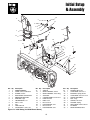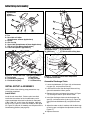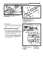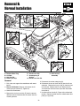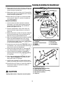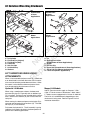
1
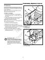
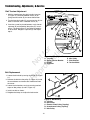
Print Vendor
Instructions
Paper Size:
How to use this file
Operator’s Manuals
• 11x17
• Body - 50 lbs brilliant white offset or equivalent
• Cover - on pre-printed two tone “Swash” stock.
Press:
• Body - 1 color, 2-sided
• Cover - 1 color, 1-sided
• Saddle stitch, face trim
*if too thick for saddle stitch, tape bind
Covers:
• FRONT COVER is present at the beginning of the file.
N
ep o
ro t fo
du r
ct
io
n
Bindery:
• BACK COVER is present at the end of the file.
• The part number for this manual (typically a 173_____ number) is
located on the front cover.
• This file may contain several manual which differ only by their covers.
See the part number at the bottom of the cover page. .
Body:
• The body for all manuals is identical regardless of the cover.
• Odd number pages are always right hand pages, even number pages
are always left hand pages.
• This instruction sheet is NOT part of the manual and must not be
printed.
R
General:
• Pages labeled “THIS PAGE INTENTIONALLY BLANK” are placement
pages and should NOT be printed.
THIS PAGE INTENTIONALLY BLANK
R
N
ep o
ro t fo
du r
ct
io
n
(FOR PLACEMENT ONLY - DO NOT PRINT)
ATTACHMENT
R
N
ep o
ro t fo
du r
ct
io
n
OPERATOR’S
MANUAL
42” Two-Stage Snowthrower
42” Snowthrower Attachment
Mfg. No.
1694238
1694874
1695099
1695360
Description
42” Two-Stage Snowthrower
42” Two-Stage Snowthrower
42” Two-Stage Snowthrower
42” Two-Stage Snowthrower
1724089
Revision M
Rev. Date 11/2008
TP10004488
N
ep o
ro t fo
du r
ct
io
n
R
Table of Contents
Troubleshooting, Adjustments & Service
Troubleshooting Chart ...................................11
Skid Shoe Adjustment ...................................12
Electric Chute Rotator Gear ..........................12
Auger Shear Pins ..........................................12
Impeller Shear Bolt ........................................12
Lift Adjustment...............................................13
Belt Tension Adjustment ................................14
Belt Replacement ..........................................14
Recommended Accessories ..............................1
Safety Rules & Information
Training ............................................................2
Preparation ......................................................2
Operation.........................................................2
Children ...........................................................3
Clearing a Clogged Discharge Chute ..............3
Service, Maintenance and Storage .................3
Emissions ........................................................3
Decals..............................................................4
Required Accessories...................................5
Recommended Accessories.........................5
Clean-Out Warning and Procedure ..............5
N
ep o
ro t fo
du r
ct
io
n
Initial Setup & Assembly
Snowthrower Components ............................15
Install Hitch ....................................................16
Assemble Discharge Chute ...........................16
Install Skid Shoes ..........................................17
Attach Deflector Control Cable Support ........17
Install Chute Rotator Switch & Harness ........17
Mount Remote Deflector Control ...................18
Mount Lift Assist Bracket (Manual Lift) ..........18
Install Snowthrower .......................................19
Features & Controls
Control Functions ............................................6
General Operating Instructions
Checks Before Starting....................................7
Engine & Ground Speed Selection..................7
Stopping & Starting .........................................7
Transporting.....................................................7
Snow Removal Suggestions............................8
Daily Storage ...................................................8
Off-Season Storage.........................................8
Removal & Normal Installation
Removal.........................................................22
Normal Installation.........................................23
Lift Variations When Using Attachments .......24
Hardware Torque Specifications
Chart..............................................................25
Maintenance
Schedule for Normal Care ...............................9
General Lubrication .........................................9
Check Auger Gear Box Oil Level ...................10
Check the Impeller Gear Box Oil Level..........10
R
Mounting Remote Deflector Control
Instructions ....................................................26
Template ........................................................27
NOTE: In these instructions, “left” and “right” are
referred to as seen from the operating position.
1
Safety Rules
& Information
This machine is capable to amputating hands and feet and throwing objects. Read these safety rules and
follow them closely. Failure to obey these rules could result in loss of control of unit, severe personal injury
or death to you, or bystanders, or damage to property or equipment. The triangle
in text signifies
important cautions or warnings which must be followed.
TRAINING
OPERATION
1. Read, understand, and follow all instructions on the
machine and in the manuals before operating this
unit. Be thoroughly familiar with the controls and the
proper use of the equipment. Know how to stop the
unit and disengage the controls quickly.
2. Never allow children to operate the equipment.
Never allow adults to operate the equipment without
proper instruction.
3. Keep the area of operation clear of all persons, particularly small children and pets.
1. Do not put hands or feet near or under rotating parts.
Keep clear of the discharge opening at all times.
2. Exercise extreme caution when operating on or
crossing gravel drives, walks, or roads. Stay alert for
hidden hazards or traffic. Do not carry Passengers.
3. After striking a foreign object, stop the engine (motor),
remove the wire from the spark plug, disconnect the
cord on electric motors, thoroughly inspect the
snowthrower for any damage, and repair the damage
before restarting and operating the snowthrower.
4. If the unit should start to vibrate abnormally, stop the
engine (motor) and check immediately for the cause.
Vibration is generally a warning of trouble.
5. Stop the engine (motor) whenever you leave the
operating position, before unclogging the collector/impeller housing or discharge guide, and when
making any repairs, adjustments, or inspections.
6. When leaving the machine unattended, disengage
the power take-off (PTO), lower the attachment, set
the parking brake, stop the engine, and remove the
key.
7. When cleaning, repairing, or inspecting make certain
the collector/impeller and all moving parts have
stopped. Disconnect the spark plug wire and keep
the wire away from the plug to prevent accidental
starting. Do not run the engine indoors except for
starting the engine or for transporting the snowthrower in or out of the building. Open the outside doors;
exhaust fumes are dangerous.
8. Exercise extreme caution when operating on slopes.
Do not attempt to clear steep slopes.
9. Never operate the snowthrower without proper
guards plates, or other safety protective devices in
place and working.
10. Never direct the discharge toward people or areas
where property damage can occur. Keep children
and others away.
11. Do not overload the machine capacity by attempting
to clear snow at too fast a rate.
12. Never operate the machine at high transport speeds
on slippery surfaces. Look behind and use care
when operating in reverse.
13. Disengage power to the collector/impeller when
snowthrower is transported or not in use.
14. Use only attachments and accessories approved by
the manufacturer of the snowthrower (such as wheel
weights, counterweights, or cabs).
15. Never operate the snowthrower without good visibility
or light. Always be sure of your footing, and keep a
firm hold on the handles. Walk, never run.
16. Never touch a hot engine or muffler.
17. Never operate the snowthrower near glass enclosures, automobiles, window wells, drop-offs, and the
like without proper adjustment of the discharge angle.
18. Never direct discharge at bystanders or allow anyone
in front of the unit.
19. Never leave a running unit unattended. Always disen-
PREPARATION
R
N
ep o
ro t fo
du r
ct
io
n
1. Thoroughly inspect the area where the equipment is
to be used and remove all doormats, sleds, boards,
wires, and other foreign objects.
2. Disengage all clutches and shift into neutral before
starting engine (motor).
3. Do not operate the equipment without wearing adequate winter outer garments. Avoid loose fitting clothing that can get caught in moving parts. Wear
footwear that will improve footing on slippery surfaces.
4. Handle fuel with care; it is highly flammable.
(a) Use an approved fuel container.
(b) Never add fuel to a running engine or hot engine.
(c) Fill fuel tank outdoors with extreme care. Never fill
fuel tank indoors. Replace fuel cap securely and
wipe up spilled fuel.
(d) Never fill containers inside a vehicle or on a truck
or trailer bed with a plastic liner. Always place containers on the ground, away from your vehicle, before
filling.
(e) When practical, remove gas-powered equipment
from the truck or trailer and refuel it on the ground. If
this is not possible, then refuel such on a trailer with a
portable container, rather than from a gasoline dispenser nozzle.
(f) Keep nozzle in contact with the rim of the fuel tank
or container opening at all times, until refueling is
complete. Do not use a nozzle lock-open device.
(g) Replace gasoline cap securely and wipe up spilled
fuel.
(h) If fuel is spilled on clothing, change clothing immediately.
5. Adjust the collector housing height to clear gravel or
crushed rock surfaces.
6. Never attempt to make any adjustments while the
engine (motor) is running (except when specifically
recommended by the manufacturer).
7. Let engine (motor) and machine adjust to outdoor
temperatures before starting to clear snow.
8. Always wear safety glasses or eye shields during
operation or while performing an adjustment or repair
to protect eye from foreign objects that may be
thrown from the machine.
TP-600-4159-01-UV-SMAN
2
Safety Decals
gage the auger and traction controls, stop engine,
and remove keys.
20. Do not operate the unit while under the influence of
alcohol or drugs.
21. Keep in mind the operator is responsible for accidents occurring to other people or property.
22. Data indicates that operators, age 60 years and
above, are involved in a large percentage of power
equipment-related injuries. These operators should
evaluate their ability to operate the unit safely enough
to protect themselves and others from injury.
23. DO NOT wear long scarves or loose clothing that
could become entangled in moving parts.
24. Snow can hide obstacles. Make sure to remove all
obstacles from the area to be cleared.
tices when refueling the unit after transportation or
storage.
8. Always follow the engine manual instructions for storage preparations before storing the unit for both short
and long term periods.
9. Always follow the engine manual instructions for
proper start-up procedures when returning the unit to
service.
10. Maintain or replace safety and instruction labels as
necessary.
11. Keep nuts and bolts tight and keep equipment in
good condition.
12. Never tamper with safety devices. Check their proper
operation regularly and make necessary repairs if
they are not functioning properly.
13. Components are subject to wear, damage, and deterioration. Frequently check components and replace
with manufacturer’s recommended parts, when necessary.
14. Check control operation frequently. Adjust and service as required.
15. Use only factory authorized replacement parts when
making repairs.
16. Always comply with factory specifications on all settings and adjustments.
17. Only authorized service locations should be utilized
for major service and repair requirements.
18. Never attempt to make major repairs on this unit
unless you have been properly trained. Improper service procedures can result in hazardous operation,
equipment damage and voiding of manufacturer’s
warranty.
19. Check shear bolts and other bolts at frequent intervals for proper tightness to be sure the equipment is
in safe working condition.
CHILDREN
N
ep o
ro t fo
du r
ct
io
n
Tragic accidents can occur if the operator is not alert to the
presence of children. Children are often attracted to the
unit and the operating activity. Never assume that children
will remain where you last saw them.
1. Keep children out of the area and under the watchful
care of another responsible adult.
2. Be alert and turn unit off if children enter the area.
3. Never allow children to operate the unit.
4. Use extra care when approaching blind corners,
shrubs, trees, or other objects that may obscure
vision.
CLEARING A CLOGGED DISCHARGE
CHUTE
Hand contact with the rotating impeller inside the discharge chute is the most common cause of injury associated with snowthrowers. Never use your hand to clean
out the discharge chute.
To clear the chute:
1. SHUT OFF THE ENGINE.
2. Wait 10 seconds to be sure the impeller blades have
stopped rotating.
3. Always use a clean out tool, not your hands.
EMISSIONS
R
1. Engine exhaust from this product contains chemicals
known, in certain quantities, to cause cancer, birth
defects, or other reproductive harm.
2. If available, look for the relevant Emissions Durability
Period and Air Index information on the engine emissions label.
SERVICE, MAINTENANCE, AND STORAGE
1. Check shear bolts and other bolts at frequent intervals for proper tightness to be sure the equipment is
in safe working condition.
2. Never store the machine with fuel in the fuel tank
inside a building where ignition sources are present
such as hot water and spacer heaters, or clothes dryers. Allow the engine to cool before storing in any
enclosure.
3. Always refer to the operator’s manual for important
details if the snowthrower is to be stored for an
extended period.
4. Maintain or replace safety and instruction labels as
necessary.
5. Run the machine a few minutes after throwing snow
to prevent freeze-up of the collector/impeller.
6. If fuel is spilled, do not attempt to start the engine but
move the machine away from the area of spillage and
avoid creating any source of ignition until fuel vapors
have dissipated.
7. Always observe safe refueling and fuel handling prac3
Safety Decals
SAFETY DECALS
All DANGER, WARNING, CAUTION and instructional
messages on your unit should be carefully read and
obeyed. Personal bodily injury can result when these
instructions are not followed. The information is for your
safety and it is important! The safety decals below are on
your unit.
This unit has been designed and manufactured to provide you with the safety and reliability you would expect
from an industry leader in outdoor power equipment
manufacturing.
Although reading this manual and the safety instructions
it contains will provide you with the necessary basic
knowledge to operate this equipment safely and effectively, we have placed several safety labels on the unit to
remind you of this important information while you are
operating your unit.
If any of these decals are lost or damaged, replace them
at once. See your local dealer for replacements.
N
ep o
ro t fo
du r
ct
io
n
These labels are easily applied and will act as a constant
visual reminder to you, and others who may use the
equipment, to follow the safety instructions necessary for
safe, effective operation.
Part No. 1716532
Auger Danger Decal
Part No. 1722674
Discharge Chute Danger Decal
Part No. 1716531
Main Operation Warning Decal
R
WHEN OPERATING
WITH SNOWTHROWER,
REAR WHEEL WEIGHTS
ARE REQUIRED.
CAUTION
Part No. 1716540
Rear Wheel Weights Required
4
1716540
Required Accessories
Required Accessories
It is required that tire chains and two rear wheel weights or Quick Tach Weights are used.
Never operate on slopes greater than 17.6% (10°).
Recommended Accessories
A rear-mounted weight box can also be added for additional traction. The maximum weight added to the tractor
should not exceed 35 lbs. per wheel, plus 100 additional pounds in the rear weight box.
For operation on slopes greater than 15% (8.5°), Quick Tach Weights, tire chains, and wheel weights are recommended. Never operate on slopes greater than 17.6% (10°).
Required Accessories
N
ep o
ro t fo
du r
ct
io
n
A Lift Lever Kit is required for some of the models covered by this manual, and must be installed as part of hitch
installation.
DANGER
Do not clean out discharge chute with hands.
Contact with moving parts inside chute will
cause serious injury. Use a clean out tool. Use
the following procedure to remove objects or
clear the chute:
1. Stop the engine. Remove the key
2. Wait 10 seconds to be sure the auger/impeller
blades have stopped rotating.
3. Always use a clean-out tool. DO NOT use your
hands.
TRACTOR CONTROLS
R
Before you begin operating the tractor and attachment,
make certain you have:
• Read and understood the instructions in the
tractor Operator’s Manual.
• Become thoroughly familiar with all of the tractor controls and their operation, including how
to safely and properly start and stop the unit.
• Practice driving in an open area, without the
attachment, to become accustomed to the unit.
5
Features &
Controls
D
CONTROL FUNCTIONS
The information below briefly describes the
function of individual controls. Operating the
tractor and attachment requires the combined
use of these controls and additional controls
whose operation is described in the tractor
Operator’s Manual.
Please take a moment
and familiarize yourself
with the name, location,
and function of these
controls so that you will
better understand the
safety and operating
instructions provided in
this manual.
C
D
B
A
E
F
N
ep o
ro t fo
du r
ct
io
n
Figure 1. Control Locations
A. Spout Rotator Switch
B. PTO Switch
C. Hydraulic Lift
D. Manual Lift
E. Deflector Control
F. Throttle Control
A. Electric Spout Rotator Switch
Controls the electric spout rotator.
B. PTO Switch
Engages and disengages the PTO to start and stop the
snowthrower.
C. Hydraulic Attachment Lift Lever
NOTE: The hydraulic lift will only work with the engine
running and the parking brake disengaged.
R
The attachment lift lever raises and lowers the attachment. To RAISE the attachment, pull the lever back. To
LOWER the attachment, move the lever forward.
D. Manual Attachment Lift Lever
The attachment lift lever raises and lowers the attachment. To RAISE an attachment, depress the release
button on top of the lever and pull back. To LOWER an
attachment, depress the release button and move the
lever forward. When lowering the attachment, be sure to
push the lever fully forward into the locked position.
TRACTOR CONTROLS
Before you begin operating the tractor and attachment,
make certain you have:
• Read and understood the instructions in the
tractor Operator’s Manual.
E. Deflector Control
• Become thoroughly familiar with all of the tractor controls and their operation, including how
to safely and properly start and stop the unit.
The deflector control changes the angle of the
snowthrower discharge deflector. Twist the handle to
unlock it, and pull/push it to change the angle.
• Practice driving in an open area, without the
attachment, to become accustomed to the unit.
F. Throttle Control
Always operate at FULL throttle.
6
General Operating
Instructions
WARNING
WARNING
Perform the Safety System Interlock test found in
your tractor Operator’s Manual. If tractor does not
pass the test, do not operate the tractor. See your
authorized dealer. Under no circumstances
should you attempt to defeat the safety system.
If auger does not start and stop when
engaging/disengaging electric clutch, see your
authorized dealer. Under no circumstances
should you attempt to defeat the safety system.
Use caution when clearing a snow covered area.
Snow can cover objects such as curbs, drop-offs,
and other obstacles. Be familiar with the area you
are clearing.
Checks Before Starting
IMPORTANT NOTE: Refer to Tractor Operator’s Manual
for important information concerning safely storing your
tractor.
To prevent an explosion or fire, never store the
tractor with fuel in the tank inside a building
where an ignition source is present.
1. Refer to the Maintenance & Adjustments sections of
this manual and perform any needed service. Also,
refer to the tractor Operator’s Manual and perform
any required service.
N
ep o
ro t fo
du r
ct
io
n
IMPORTANT NOTE
2. Remove any objects from the work area which might
be caught in, or thrown by, the auger.
Always raise the snowthrower before turning or
backing up to prevent damage to the unit.
3. Before starting the engine, clear the auger of any ice
particles which may cause damage to auger.
DANGER
4. Adjust the deflector and skid shoes to desired height.
See Skid Shoe Adjustment and Deflector Adjustment.
OPERATING ON SLOPES CAN BE DANGEROUS
5. Make sure all hardware is present and secure.
Never operate on slopes greater than 17.6% (10°)
which is a rise of 3-1/2 feet (106cm) vertically in
10 feet (607cm) horizontally.
Engine & Ground Speed Selection
Always run the engine at full throttle.
Operate the unit at a slow ground speed when
driving onto slope. Avoid using brakes to control
ground speed.
Normally, a slow ground speed is best for throwing snow.
The deeper or heavier the snow, the slower the recommended ground speed.
When operating on slopes that are greater than
15 % (8.5°) but less than 17.6%, use additional
wheel weights or counterweights.
R
Starting & Stopping
1. Start the tractor engine. Set engine throttle FULL.
In addition to counterweights, use extra caution
when operating on slopes. Drive UP and DOWN
the slope, never across the face, use caution
when changing directions and DO NOT START
OR STOP ON SLOPE.
2. Lower the snowthrower.
3. Engage the electric clutch switch. Snowthrower auger
should rotate. Disengage the electric clutch switch.
Snowthrower auger should stop.
4. Adjust the throttle to full speed. Select the proper
ground speed.
For additional traction, tire chains and a weight
box can be added. Maximum weight added to
tractor should not exceed 50 lbs. per wheel and
100 additional lbs. in weight box.
5. To stop tractor movement, depress the clutch/brake
pedal. To stop the snowthrower, disengage the electric clutch. Before leaving the seat, disengage the
electric clutch, set the parking brake, stop the engine,
remove the key, and wait for all moving parts to stop.
Transporting
1. Disengage the electric clutch and then raise the
snowthrower.
2. Adjust ground speed according to surface conditions.
3. Select a low ground speed when transporting on a
slippery surface.
7
General Operating Instructions
Snow Removal Suggestions
• Determine the best snow removal pattern before
beginning.
• Wind direction is an important factor to consider.
Rotate the spout to discharge snow downwind.
• Plan the pattern so that you avoid throwing snow on
cleared areas and on yourself as you are operating.
• When land contour permits, it is best to travel in the
longest direction to minimize turning.
• In very deep or heavy snow, it may be necessary to
make the first pass with snowthrower partially raised,
backing up every few feet and lowering the
snowthrower to clear the snow left on the surface.
Also, it may be necessary to slice off less than the full
width of the auger or reduce ground speed.
DANGER
N
ep o
ro t fo
du r
ct
io
n
• If snow stops flowing freely from the spout, back
away until the snowthrower clears itself.
If the auger stalls or the chute plugs, DISENGAGE
THE ELECTRIC CLUTCH, STOP THE ENGINE AND
REMOVE THE KEY. SET THE PARKING BRAKE.
WAIT FOR MOVING PARTS TO STOP. Remove
the foreign object or clear the spout with a piece
of wood before restarting the engine. Never place
hands into auger housing or spout to clear
jammed object. Auger may rotate when object is
removed.
Daily Storage
R
1. Run the snowthrower a few minutes after blowing
snow to prevent freeze-up of auger.
2. Allow tractor engine to cool before storing in any
enclosure.
Off-Season Storage
1. Remove snowthrower from the tractor.
2. Use water pressure or a brush to thoroughly clean
the housing.
3. Paint, or lightly coat with oil, any area where paint
has been worn or chipped away.
4. Lubricate the snowthrower.
5. Store the snowthrower and hitch in a dry place.
8
Maintenance
WARNING
General Lubrication
Lubricate the snowthrower as shown in Figure 2. Where
an oil can is shown use 30 weight oil. Where a grease
gun is shown, use lithium grease. Lubricate the following
areas:
To avoid serious injury, perform maintenance on
the unit only when the engine is stopped and all
moving parts have stopped. Always remove the
ignition key before beginning maintenance or
adjustments to prevent accidental starting of the
engine.
• Oil the chute deflector.
• Oil the deflector locking control.
• Grease the chute ring gear.
Schedule For Normal Care
• Grease the snowthrower-hitch pivot points.
Care Required
Schedule
Clean snow and ice from
snowthrower.
Lubricate snowthrower.
After each use.
• Grease the the auger shaft grease fittings.
N
ep o
ro t fo
du r
ct
io
n
Every 10 hours or at
least once a year.
At least once a year.
R
Check gear box oil level.
• Grease the auger bearings.
Figure 2. Lubrication Points
9
Maintenance
Check Auger Gearbox Oil Level
A
Perform this check every season.
1. Remove the plug (A, Figure 3) from the side of the
auger gear box.
2. Add Simplicity Winter Weight Worm Gear Oil until the
oil level is even with the fill plug hole.
3. Reinstall the plug (A).
Figure 3. Auger Gear Box Oil
A. Fill Plug
Check the Impeller Gear Box Oil Level
N
ep o
ro t fo
du r
ct
io
n
Perform this check every season. The gear box oil
capacity is 12 oz. The gear box can be accessed from
the rear of the snowthrower attachment.
1. Remove the oil fill plug (A, Figure 4) from the top of
the gear box.
2. Insert a piece of wire into the gear box to check the
oil level.
4. Reinstall the plug.
R
3. Add 85W-90 gear lube oil if required. The box should
be approximately half full. Air space is required for oil
expansion.
Figure 4. Impeller Gear Box Oil
A. Fill Plug
10
A
Troubleshooting,
Adjustments, & Service
TROUBLESHOOTING
WARNING
While normal care and regular maintenance will extend
the life of your equipment, prolonged or constant use
may eventually require that service be performed to
allow it to continue operating properly.
To avoid serious injury, perform maintenance on
the tractor or mower only when the engine is
stopped and the parking brake engaged.
Always remove the ignition key, disconnect the
spark plug wire and fasten it away from the plug
before beginning the maintenance, to prevent
accidental starting of the engine.
The troubleshooting guide below lists the most common
problems, their causes and remedies.
See the information on the following pages for instructions on how to perform most of these minor adjustments
and service repairs yourself. If you prefer, all of these
procedures can be performed for you by your local
authorized dealer.
CAUSE/SOLUTION
1 Snowthrower auger does not rotate.
A. Electric clutch not engaged. Engage electric clutch.
B. Foreign material is blocking auger. STOP engine. Remove
key. Unplug auger with piece of wood. Read WARNING on
page 5.
C. Drive chain broken. Replace parts as required.
N
ep o
ro t fo
du r
ct
io
n
PROBLEM
A. Electric clutch brake not operating properly. See your dealer.
3 Auger rotates, but snow
is not thrown far enough.
A. Engine RPM too slow. Set throttle to FULL.
B. Ground speed too fast. Use slow ground speed.
C. Snowthrower discharge chute clogged. STOP engine. Remove
key. Unplug discharge chute using a piece of wood. Read
WARNING on page 5.
D. Shear pin/bolt broken.
4 Scraper bar does not clean
down to hard surface.
A. Skid shoes not properly adjusted. Adjust skid shoes.
B. Lift height out of adjustment. See ADJUSTMENTS section.
C. No down pressure. See Hitch Installation Instructions.
R
2 Auger does not stop when
electric clutch is disengaged.
5 Snowthrower picks up and
throws stones on gravel drive.
A. Skid shoes not properly adjusted for ground surface.
Adjust skid shoes.
B. Too much downward pressure on snowthrower. Raise
snowthrower slightly.
C. Downward pressure out of adjustment.
See ADJUSTMENT section.
6 Tractor does not have sufficient traction.
A. Tractor too light at rear wheels.
Use Quick Tach weights, wheel weights, and tire chains.
7 Tractor not stable on sloping surfaces.
A. Ground speed too fast. Reduce speed.
B. Tractor not properly weighted.
See Recommended Accessories, page 1.
C. Slope grade too steep. See Safety Section.
Use Quick Tach weights, wheel weights, and tire chains.
8 Chute does not rotate.
A. Rotator gears out of adjustment.
B. Wire harness disconnected.
11
Troubleshooting, Adjustments, & Service
Skid Shoe Adjustment
On smooth surfaces such as concrete or asphalt, the
scraper bar should scrape the surface. On surfaces
such as gravel, the scraper bar should be set high
enough so that it will not pick up debris.
1. Loosen the nuts securing the skid shoes (see
Figure 5).
A
2. Raise or lower the scraper bar to the desired height.
Use wood blocks to hold the snowthrower in position.
3. Set the skid shoes so that they are in contact with the
ground and tighten the skid shoe nuts.
Figure 6. Chute Rotator Motor Adjustment (Left Side
Mount)
A. Capscrews
N
ep o
ro t fo
du r
ct
io
n
Loosen Nuts
to Adjust
A
Figure 5. Adjusting Skid Shoes
Electric Chute Rotator Gear
Figure 7. Chute Rotator Motor Adjustment (Right
Side Mount)
A. Screws
1. Remove the cover and loosen the three screws (A,
Figure 6 or 7) securing the electric spout rotator
motor.
3. Reinstall the cover.
R
2. Adjust the motor so that it meshes with the discharge
chute ring gear and tighten the adjustment screws
(A).
Impeller shear bolt located
on shaft, in front of impeller.
Auger Shear Pins
The auger shear pins (A, Figure 8) are designed to break
if the auger strikes an object. Replace the shear pins
with original factory specification shear pins ONLY.
Impeller Shear Bolt
A
The impeller shear bolt is designed to break if the auger
strikes an object. The impeller shear bolt is located in
the impeller shaft between the impeller and auger gear
box. Replace the shear bolt ONLY with a 5/16-18 x 1
Grade 5 bolt.
Figure 8. Shear Pins & Bolt
A. Auger Shear Pins
12
A
Troubleshooting, Adjustments, & Service
Lift Adjustment
C
In the fully raised position the attachment should be 4”-5”
off the ground. In the fully lowered position, the lift rod
should compress the spring creating downward pressure
on the snowthrower.
B
A
NOTE: Always adjust the lift height before and after
adjusting the downward pressure.
LIFT HEIGHT ADJUSTMENT
1. Fully raise the attachment lift. The snowthrower
should be approximately 4”-5” off the ground. If not,
go to step 2.
2. Lower the snowthrower and adjust the front set collar
(A, Figure 9) to achieve the correct lift height.
DOWNWARD PRESSURE ADJUSTMENT
NOTE: Check that the lift bar or lock plate (Figures 14 &
15) are in the correct positions
1. Place the lift in the fully raised position.
N
ep o
ro t fo
du r
ct
io
n
2. Release the rear set collar (C, Figure 9).
Figure 9. Adjusting Lift Rod
A. Front Set Collar
B. Spring
C. Rear Set Collar
3. Slide the set collar (C) forward until it is slightly compressing the spring. Tighten the set collar screw. Do
not over-compress the lift rod spring.
LIFT ASSIST ADJUSTMENT (MANUAL LIFT ONLY)
1. Tighten the lift assist bolt (A, Figure 10) to increase
the amount of lift assist.
A
R
IMPORTANT NOTE
DO NOT OVER-COMPRESS THE SPRING.
In addition to providing downward pressure,
the spring is an elastic medium that absorbs
shocks caused by bumps and cracks in
ground surfaces. Over-compressing the
spring defeats this and may cause damage
to the unit.
Figure 10. Lift Assist Adjustment
A. Lift Assist Bolt
13
Troubleshooting, Adjustments, & Service
Belt Tension Adjustment
1. With the snowthrower drive belt installed, trunnion
(A, Figure 11) should be between marks (G) on
spring tension bracket (B) for correct belt tension.
2. Turn belt tension handle (C) to move trunnion (A) forward or rearward until it is between marks (G).
3. If trunnion cannot be placed between marks, loosen
capscrew (D) and reposition idler pulley (E) as necessary. The pivot bracket (F) should be perpendicular to the hitch. Retighten capscrew (D) and repeat
step 2.
C
A
A
G
G
E
N
ep o
ro t fo
du r
ct
io
n
B
D
F
Figure 11. Adjusting Belt Tension
A. Trunnion
E. Idler Pulley
B. Spring Tension Bracket
F. Pivot Bracket
C. Handle
G. Tension Marks
D. Capscrew
Belt Replacement
E
1. Loosen the drive belt by turning the handle (C, Figure
11).
R
C
B
2. Remove the belt from the pulley (D, Figure 12) inside
the snowthrower and remove the snowthrower from
the tractor.
3. Loosen the lockwashers and nuts securing two belt
stops on idler pulleys (A and E, Figure 12).
A
4. Install new belt as shown.
5. Retighten belt stops and adjust the belt tension.
D
Figure 12. Belt Routing
A. V-Pulley
B. Idler Pulley
C. Electric Clutch Pulley (V-pulley)
D. Snowthrower Pulley (V-pulley)
E. Idler Pulley
14
Initial Setup
& Assembly
10
4
9
11
8
7
6
12
5
3
30
13
31
29
28
14
27
2
26
32
24
N
ep o
ro t fo
du r
ct
io
n
1
33
23
22
25
21
18
16
15
20
19
R
17
Ref Qty
1
1
2
3
3
3
4
1
5
1
6
2
7
2
8
2
9
1
10
1
11
2
Description
SNOWTHROWER
GUIDE, Chute, Hold-Down
SCREW, Plastite
DISCHARGE CHUTE ASSY.
MOUNTING BRACKET
WASHER, Large
LOCKWASHER, 1/4”
NUT, 1/4-20
PIN
HAIR PIN CLIP
CAPSCREW, 1/4-20 x 7/8
Ref Qty
12
1
13
1
14
1
15
1
16
1
17
2
18
2
19
1
20
1
21
1
22
1
Description
SWITCH
WIRE HARNESS, Switch
WIRE HARNESS, Trailer Plug
SUPPORT
CARRIAGE BOLT, 5/16-18 x 1
HAIR PIN CLIP
ROD, Latch
NUT, 5/16-18
LOCKWASHER, 5/16
NUT, 5/16-18
LOCKWASHER, 5/16
Figure 13. Initial Setup (Left Side Mount Shown)
15
Ref Qty
23
1
24
1
25
1
26
1
27
1
28
1
29
1
30
1
31
1
32
1
33
1
Description
WASHER, Over-size
CAPSCREW, 5/16-18 x 1
BRACKET, Spring Anchor
CAPSCREW, 5/16-18 x 4-1/2
SPRING RETAINER
NUT, Cage
SPRING, Lift Assist
ANCHOR, Spring
RING GEAR, Reinforcement
TIE WRAP
WIRE HARNESS, Motor
Initial Setup & Assembly
Snowthrower
& Dozer
Applications
E
A
A
D
F
B
C
D
B
Figure 14. Connect Lift Link - Manual Lift Models
A. Pin
B. Rear Hole of Lift Bar
(Snowthrower & Dozer Applications)
C. Spacer
D. Hair Pin Clip
E. Upper Hole (Snowthrower & Dozer Applications)
F. Slot of Lift Link (Mower Applications)
G. Lower Hole (Mower Applications)
Figure 16. Assemble Discharge Chute
A. Plastite Screw
C. Chute Ring
B. Hold-Down
D. Reinforcement Ring Gear
N
ep o
ro t fo
du r
ct
io
n
A
C
A
B
F
C
D
E
Figure 15. Install Lock Plate - Hydraulic Lift Models
A. Lift Cylinder
D. Lock Plate
B. Flat Head Pin (Original)
E. Hair Pin Clips
C. Flat Head Pin (New)
F. Lift Shaft Assy.
R
Figure 17. Discharge Chute Motor Adjustment
A. Adjustment Screws
Assemble Discharge Chute
INITIAL SETUP & ASSEMBLY
1. Locate the hold downs (B, Figure 16), reinforcement
ring gear (D), and plastite screws (A).
NOTE: Some of the following setup procedures may
already be completed.
2. Lubricate the base of the discharge chute and ring
gear with automotive lithium grease.
Install Hitch
3. Remove the cover and loosen the screws (A, Figure
17) securing the electric spout rotator motor.
Install the sub-frame hitch. Refer to sub-frame hitch
installation instructions for hitch modifications and 2stage snowthrower drive belt installation for Conquest /
1700 / 2700 / GT and Lift Lever Kit 1694148. Note that
the lift bar (B, Figure 14, manual lift models) or lock plate
(D, Figure 15, hydraulic lift models) must be placed in the
snowthrowing position (see page 22).
4. Install the discharge chute and reinforcement ring
gear (D), and secure to the chute ring (C, Figure 16)
using the three hold downs (B) and plastite screws
(A).
5. Adjust the motor so that it meshes with the discharge
chute ring gear and tighten the adjustment screws (A,
Figure 17).
6. Replace the cover.
16
Initial Setup & Assembly
B
A
B
C
E
C
F
A
D
Figure 19. Deflector Control Cable Support Arm
A. Support Arm
B. 5/16-18 x 1 Carriage Bolt
C. Lockwasher & Nut
Figure 18. Skid Shoe Installation
A. Carriage Bolt, 3/8-16 x 3/4”
B. Snowthrower Housing
C. Skid Shoe
D. Washer
E. Lockwasher
F. Hex Nut
N
ep o
ro t fo
du r
ct
io
n
Install Skid Shoes
G
H
F
1. Install the skid shoes using 3/8-16 x 3/4” carriage
bolts, washers, lockwashers, and nuts as shown in
Figure 18.
2. Adjust the skid shoes. See Adjustments section.
Attach Deflector Control Cable Support Arm
1. Assemble the deflector control cable support arm (A,
Figure 19) to the left side of the snowthrower using
one 5/16-18 x 1” carriage bolt (B), lockwasher, and
nut (C) using the holes shown.
Install Chute Rotator Switch and Harness
E
R
A
1. Remove the plug from the switch mounting hole in
the right side of the dashboard.
D
2. Route the switch harness (C, F, Figure 20) through
the frame and dashboard as shown.
3. Install the switch (G) in the dashboard and connect
the upper end of the switch harness (F) to it.
C
B
4. Connect the red/yellow power lead (H) to the
red/yellow tractor harness lead (E). Connect the
black power lead to the black tractor harness lead.
Figure 20. Install Power Port & Switch
A. Rotator Motor Harness
B. Trailer Plug
C. Switch Harness Lower Plug
D. Plug Hole (Frame)
E. Tractor Harness Leads
F. Switch Harness Upper Plug
G. Switch
H. Power Leads
5. Mount the trailer plug socket (B) in the frame at location (D). Connect the trailer plug lead (B) to the lower
switch harness connector (C).
6. Do not connect the snowthrower wire harness (A) at
this time.
17
Initial Setup & Assembly
A
B
C
E
D
D
A
B
Figure 22. Install Remote Deflector Control
A. Clevis Pin
B. Deflector Control Handle
C. Mounting Bracket
D. Hair Pin Clip
N
ep o
ro t fo
du r
ct
io
n
C
Figure 21. Mount Control Bracket - Current Models
A. 1/4-20 x 7/8 Capscrews
D. 1/4-20 Nuts
B. 1/4 x 1-1/4 Flatwashers
E. Mounting Bracket
C. 1/4 Lockwashers
Mount Remote Deflector Control
B
A
1. Using the template included in the back of this manual, drill two 9/32” holes in the dashboard to mount the
remote chute control. See MOUNTING REMOTE
DEFLECTOR CONTROL in the back of this book.
2. Mount the mounting bracket (E, Figure 21) to the
dashboard. Secure with two 1/4-20 x 7/8 capscrews
(A), lockwashers (C), and large flat washers (B).
R
3. Install the remote deflector control handle (B, Figure
22) in the mounting bracket (C) and secure with a
clevis pin (A) and hair pin clip (D).
Mount Lift Assist Bracket
(Manual Lift Models Only)
Figure 23. Install Lift Assist Bracket
A. Lift Assist Bracket
B. Capscrew, 5/16-18 x 1
C. Large Washer
D. Lockwasher & Nut
1. Mount the lift assist bracket (A, Figure 233) to the
snowthrower. Slide the bracket back so that it
engages the snowthrower housing. Secure using a
5/16-18 x 1 capscrew (B), large washer (C), lockwasher and nut (D).
18
C
D
Initial Setup & Assembly
Install Snowthrower
CONNECT TO HITCH
1. Position the snowthrower in front of the hitch. Insert
the hitch pin (A, Figure 24) through the snowthrower
and hitch on both sides of the snowthrower. Secure
with a hair pin clip (B). Use the back set of hitch
holes (see inset).
NOTE: The hitch pin (A) goes in between the belt,
NOT below or above it.
B
A
INSTALL LIFT ROD
N
ep o
ro t fo
du r
ct
io
n
Figure 24. Install Snowthrower
A. Hitch Pin
B. Hair Pin Clip
B
2. Attach the front of the lift rod assembly (A, Figure 25)
to the lift arm (C). Secure with a hair pin clip (B).
A
C
R
Figure 25. Lift Rod - Front
A. Lift Rod Assembly
B. Hair Pin Clip
C. Lift Arm
3. Connect the rear of the lift rod assembly (A, Figure
26) to the tractor lift arm extension (C). Secure with a
hair pin clip (B).
NOTE: If necessary, perform the lift rod adjustments
found in the Troubleshooting, Adjustments, & Repair
section.
NOTE: See Lift Lever Kit Installation Instructions for lift
rod installation.
A
C
B
Figure 26. Lift Rod - Front
A. Lift Rod Assembly
B. Hair Pin Clip
C. Lift Arm
19
Initial Setup & Assembly
C
B
A
D
E
F
Figure 27. Install Lift Assist
A. Spring
B. Pal Nut
C. Spring Retainer
D. Assist Bracket
E. Capscrew, 5/16-18 x 4-1/2
F. Spring Anchor
N
ep o
ro t fo
du r
ct
io
n
A
Figure 28. Rotator Motor Electrical Connection (Left
Side Mount)
A. Wire Harness
INSTALL LIFT ASSIST SPRING (MANUAL LIFT ONLY)
4. Install the spring anchor (F, Figure 27) on the
bumper.
5. Install the lift assist spring (A), spring retainer (C), nut
(B), and capscrew (E) through the assist bracket (D).
Tighten until the desired amount of lift assist is
achieved.
E
B
R
F
C
A
CONNECT ELECTRICAL HARNESS (UNITS WITH LEFT
SIDE MOUNTED MOTORS)
A
6. Route the wire harness (A, Figure 28) along the
remote deflector control cable and secure with two
wire ties. Connect the chute rotator harness plug (A,
Figure 30) to the tractor plug (B). Make certain it will
not be caught any linkages or moving parts.
D
Figure 29. Rotator Motor Electrical Connection
(Right Side Mount)
A. Wire Harness
B. Wire Tie
C. Engine Shield
D. Clip
E. Hole in Housing
F. Rotator Motor
CONNECT ELECTRICAL HARNESS (UNITS WITH RIGHT
SIDE MOUNTED MOTORS)
6. Raise the hood and route the wire harness (A, Figure
29) along the edge of the frame. Connect wire tie (B)
loosely around the wire harness (A) and engine
shield (C). Route the wire harness (A) through the
lowest opening in grill as shown. Slide clip (D) onto
hole (E). Place harness (A) into clip (D).
Note: Leave the wire tie (B) loose to aid in seasonal
removal of snowthrower.
20
Initial Setup & Assembly
B
C
B
A
D
A
B
Figure 30. Rotator Motor Electrical Connection
A. Rotator Motor Harness & Plug
B. Tractor Plug
E
INSTALL DRIVE BELT
N
ep o
ro t fo
du r
ct
io
n
Figure 31. Belt Routing
A. Snowthrower Pulley (V-pulley)
B. Back-side Idler Pulley
C. Electric Clutch Pulley (V-pulley)
D. Idler Pulley (V-pulley)
E. Hitch Pin
7. Route the drive belt as shown in Figure 31. Note
that the back of the belt rides in the back-side idlers
(B).
NOTE: The snowthrower hitch pin (E) goes in
between the belt, NOT below or above it.
8. With the snowthrower drive belt installed, the trunnion (A, Figure 32) should be between the marks (G)
on spring tension bracket (B) for correct belt tension.
Turn belt tension handle (C) to move trunnion forward or rearward until between marks.
B
A
G
C
A
G
E
R
If trunnion cannot be placed between marks, loosen
capscrew (D) and reposition idler pulley (E) as necessary. The pivot bracket (F) should be perpendicular to snowthrower hitch.
D
Figure 32. Adjusting Belt Tension
A. Trunnion
E. Idler Pulley
B. Spring Tension Bracket
F. Pivot Bracket
C. Handle
G. Tension Marks
D. Capscrew
21
F
Removal &
Normal Installation
G
B
A
C
N
ep o
ro t fo
du r
ct
io
n
F
G
H
E
Figure 33. Removal
A. Rotator Motor Plug
B. Lift Rod
C. Hair Pin Clip
D. Hitch Pin & Clip
R
D
E. Clevis Pin & Clip
F. Assist Spring &
Anchor
G. Clevis Pin & Hair Pin
Removal
H. RH Lift Lever
Assembly
5. Disconnect the rotator motor plug (A).
1. Fully raise and support the snowthrower with wood
blocks.
3. Lower the snowthrower.
6. Disconnect the rear of the lift rod (B) from the lift arm
extension. Remove the hair pin clip (C) from the front
of the lift rod. Remove the lift rod. Remove the lift
arm extension from the tractor (see Hitch Installation
Instructions).
4. Remove the clevis pin and clip (E) from the remote
deflector control and disconnect the control from the
mounting bracket.
7. Use the trunnion handle (C, Figure 34) to relieve belt
tension. Remove the belt from the snowthrower drive
pulley (A, Figure 35).
2. Manual Lift Models: Release and remove the lift
assist spring and anchor (F, Figure 33).
22
Removing & Installing the Snowthrower
8. Remove the hitch pin and clip (D, Figure 33) from the
snowthrower and remove the snowthrower. Reinstall
all pins and clips to prevent loss.
9. Remove the clevis pin and hair pin (G, Figure 33 RH
manual lift models) frame mounted bracket. Reinstall
all pins and clips to prevent loss.
10. Return the lift bar (B, Figure 14, manual lift models)
or lock plate (D, Figure 15, hydraulic lift models) to
lawn mowing position.
B
Normal Installation
C
A
A
G
G
E
1. Install the sub-frame hitch (see Hitch Installation
Instructions). Be sure to install the down pressure
lock plate or place the lift link in the snowthrower
position (see Figures 14 & 15).
2. Place the snowthrower in front of the tractor and
secure to the hitch using the hitch pin and clip (D,
Figure 33).
N
ep o
ro t fo
du r
ct
io
n
3. Route the drive belt as shown in Figure 35. Note that
the back of the belt rides in the back-side idler (B).
Note that the pin (E) goes between the belt.
D
4. With the snowthrower drive belt installed, trunnion (A,
Figure 34) should be between the marks (G) on
spring tension bracket (B) for correct belt tension.
Turn belt tension handle (C) to move trunnion forward
or rearward until between marks.
F
Figure 34. Adjusting Belt Tension
A. Trunnion
E. Idler Pulley
B. Spring Tension Bracket
F. Pivot Bracket
C. Handle
G. Tension Marks
D. Capscrew
5. Connect the rear of the lift rod (B, Figure 33) to the lift
arm extension. Use a hair pin clip (C) to secure the
front of the lift rod to the snowthrower.
6. Connect the rotator motor plug (A). Route the harness along the deflector control cable as shown.
B
R
7. Install the remote chute deflector control to the
mounting plate and secure with a clevis pin and clip
(E, Figure 33).
8. Fully raise and support the snowthrower with wood
blocks. Manual Lift Models: Install the lift assist
spring and anchor (F, Figure 33).
B
C
A
D
9. Install lift lever assembly (H, Figure 33 RH lift lever
models) and secure with clevis pins and hair pins (G)
E
10. Place the lift bar (B, Figure 14, manual lift models) or
lock plate (D, Figure 15, hydraulic lift models) in
snowthrowing position.
Figure 35. Belt Routing
A. Snowthrower Pulley (V-pulley)
B. Back-side Idler Pulley
C. Electric Clutch Pulley (V-pulley)
D. Idler Pulley (V-pulley)
E. Hitch Pin
CAUTION
Spring under tension. Keep clear of pinch points.
23
Lift Variations When Using Attachments
Snowthrower
& Dozer
Applications
Snowthrower
& Dozer
Applications
E
A
A
B
F
C
D
E
C
B
D
Mower
Applications
Mower
Applications
G
A
B
N
ep o
ro t fo
du r
ct
io
n
A
F
G
F
E
Figure 36. Lift Lock Plate - Hydraulic Lift Models
A. Lift Cylinder
B. Flat Head Pin (Original)
C. Flat Head Pin (New)
D. Lock Plate
E. Hair Pin Clips
F. Lift Shaft Assy.
G. Washers
C
D
Figure 37. Lift Link - Manual Lift Models
A. Pin
B. Rear Hole of Lift Bar
(Snowthrower & Dozer Applications)
C. Spacer
D. Hair Pin Clip
E. Upper Hole (Snowthrower & Dozer Applications)
F. Slot of Lift Link (Mower Applications)
G. Lower Hole (Mower Applications)
R
LIFT VARIATIONS WHEN USING
ATTACHMENTS
When a front-mounted attachment such as a snowthrower or dozer blade is used with the tractor, the lift mechanism must be locked to provide downward force. When
the mower is reinstalled the downward pressure lock
must be released so that the mower can float.
Hydraulic Lift Models
Manual Lift Models
When using a snowthrower or dozer, the downward
pressure lock plate (D, Figure 36) and an additional pin
(C) is installed. These parts are included with the attachment. Note that the washers (G) are not used with the
lock plate.
NOTE: These instructions apply to Conquest / 1700 /
2700 / YT Series tractors or Broadmoor / 1600 / 2600 /
LT Series tractors equipped with a lift lever kit 1694148.
The lift link is installed differently depending on what
attachment is being used. Refer to Figure 37 for link
installation information.
When mowing, the downward pressure lock plate (D) is
removed and replaced with two washers (G). The additional pin (C) is also removed.
Fully lower the hydraulic lift. The lift assembly is spring
loaded so it will need to be held in the down position to
perform of the following procedures.
24
25
N
ep o
ro t fo
du r
ct
io
n
R
Mounting Remote Deflector Control
Line Template Up
with Edge of
Plastic
Dashboard
Figure 37. Template Location
N
ep o
ro t fo
du r
ct
io
n
Mark and Drill One
9/32” Hole
Mount Bracket and
align with Line
Mark and Drill One
9/32” Hole
MOUNTING REMOTE DEFLECTOR
CONTROL
NOTE: Read through instructions before beginning.
1. Open the hood.
R
2. Cut out the template and place it on the lower left corner of the dashboard as shown above.
3. Mark and drill one 9/32” hole using the template to
locate the holes.
E
4. Mount the remote deflector mounting bracket (E,
Figure 38) control to the dashboard using upper hole.
5. Align center of lower hole to dashed line on template
and mark. Remove the remote deflector mounting
bracket (E). Drill one 9/32” hole using the marked
location.
D
A
C
6. Mount the remote deflector mounting bracket (E) control to the dashboard. Secure using two 1/4-20 x 7/8”
capscrews (A) through the bracket (E) and dashboard.
B
Figure 38. Mount Control Bracket - Current Models
A. 1/4-20 x 7/8 Capscrews
D. 1/4-20 Nuts
B. 1/4 x 1-1/4 Flatwashers
E. Mounting Bracket
C. 1/4 Lockwashers
7. Secure with 1/4 x 1-1/4 flatwashers (B), lockwashers
(C), and nuts (D) on the BACKSIDE of the dashboard.
DO NOT OVER-TORQUE. Over-torquing may
crack the dashboard.
26
N
ep o
ro t fo
du r
ct
io
n
Template
Line Template Up
with Top Crease
of Plastic
Dashboard
Mark and Drill One
9/32” Hole
R
Line Template Up
with Edge of
Plastic
Dashboard
27
N
ep o
ro t fo
du r
ct
io
n
R
www.SimplicityMfg.com
www.Snapper.com
www.MasseyLawn.com
www.AGCOLawn.com
Briggs & Stratton Power Products Group, L.L.C.
Copyright © 2008 Briggs & Stratton Corporation
Milwaukee, WI USA. All Rights Reserved
www.BRIGGSandSTRATTON.com