1
Operating Instructions
Maintenance Guide 1
Read this manual carefully before you use this product and keep it handy for future
reference.
For safety, please follow the instructions in this manual.
Introduction
This manual contains detailed instructions on the operation and maintenance of this machine. To get
maximum versatility from this machine all operators should carefully read and follow the instructions in
this manual. Please keep this manual in a handy place near the machine.
Please read the Safety Information before using this machine. It contains important information related
to USER SAFETY and PREVENTING EQUIPMENT PROBLEMS.
Trademarks
Microsoft®, Windows® and Windows NT ® are registered trademarks of Microsoft Corporation in the United States and/or other countries.
IPS-PRINT™ Printer Language Emulation© Copyright 1999-2000, XIONICS
DOCUMENT TECHNOLOGIES, INC., All Rights Reserved.
Other product names used herein are for identification purposes only and might
be trademarks of their respective companies. We disclaim any and all rights in
those marks.
Notes:
Some illustrations might be slightly different from your machine.
Certain options might not be available in some countries. For details, please contact your local dealer.
Note
The proper names of the Windows operating systems are as follows:
• Microsoft® Windows® 95 operating system
• Microsoft® Windows® 98 operating system
• Microsoft® Windows® Millennium Edition (Windows Me)
• Microsoft® Windows ® 2000 Professional
• Microsoft® Windows ® 2000 Server
• Microsoft® Windows NT® Server operating system Version 4.0
• Microsoft® Windows NT® Workstation operating system Version 4.0
i
Safety Information
When using your printer, the following safety precautions should always be followed.
Safety During Operation
In this manual, the following important symbols are used:
R WARNING:
Indicates a potentially hazardous situation which, if instructions
are not followed, could result in death or serious injury.
R CAUTION:
Indicates a potentially hazardous situation which, if instructions are
not followed, may result in minor or moderate injury or damage to
property.
R WARNING:
• Connect the power cord directly into a wall outlet and never use an extension cord.
• Disconnect the power plug (by pulling the plug, not the cable) if the
power cable or plug becomes frayed or otherwise damaged.
• To avoid hazardous electric shock or laser radiation exposure, do not
remove any covers or screws other than those specified in this manual.
• Turn off the power and disconnect the power plug (by pulling the plug,
not the cable) if any of the following conditions exists:
• You spill something into the equipment.
• You suspect that your equipment needs service or repair.
• Your equipment's cover has been damaged.
• Do not incinerate spilled toner or used toner. Toner dust might ignite
when exposed to an open flame.
• Disposal can take place at our authorized dealer or at appropriate collection sites.
• Dispose of the used toner cartridge in accordance with the local regulation.
ii
R CAUTION:
• Protect the equipment from dampness or wet weather, such as rain, snow,
and so on.
• Unplug the power cord from the wall outlet before you move the equipment.
While moving the equipment, you should take care that the power cord will
not be damaged under the equipment.
• When you disconnect the power plug from the wall outlet, always pull the
plug (not the cable).
• Do not allow paper clips, staples, or other small metallic objects to fall inside
the equipment.
• Keep toner (used or unused) and toner cartridge out of the reach of children.
• For environmental reasons, do not dispose of the equipment or expended
supply waste at household waste collection points. Disposal can take place
at an authorized dealer or at appropriate collection sites.
• The inside of the machine could be very hot. Do not touch the parts with a
label indicating the “hot surface”. Otherwise it could cause a personal burn.
• Our products are engineered to meet high standards of quality and functionality, and we recommend that you only use the expendable supplies available at an authorized dealer.
iii
ENERGY STAR Program
As an ENERGY STAR Partner, we have determined
that this machine model meets the ENERGY STAR
Guidelines for energy efficiency.
The ENERGY STAR Guidelines intend to establish an international energy-saving system for
developing and introducing energy-efficient office equipment to deal with environmental issues, such as global warming.
When a product meets the ENERGY STAR Guidelines for energy efficiency, the Partner shall
place the ENERGY STAR logo onto the machine model.
This product was designed to reduce the environmental impact associated with office equipment by means of energy-saving features, such as Low-power mode.
❖ Low-power Mode (Energy Saver mode)
This printer automatically lowers its power consumption 60 minutes after the
last operation has been completed. To exit Low-power (Energy Saver) mode,
press any key on the operation panel. For details about how to configure Energy Saver mode, see “Making Printer Settings with the Operation Panel” in Administrator Reference 2 as a PDF file on the CD-ROM.
❖ Specifications
Energy Saver mode
iv
Power Consumption
45 W or less
Default Time
60 minutes
Recovery Time
120 seconds or less
How to Read This Manual
Symbols
In this manual, the following symbols are used:
R WARNING:
This symbol indicates a potentially hazardous situation which, if instructions
are not followed, could result in death or serious injury.
R CAUTION:
This symbol indicates a potentially hazardous situation which, if instructions
are not followed, may result in minor or moderate injury or damage to property.
* The statements above are notes for your safety.
Important
If this instruction is not followed, paper might be misfed, or data might be lost.
Be sure to read this.
Preparation
This symbol indicates the prior knowledge or preparations required before operating.
Note
This symbol indicates precautions for operation, or actions to take after misoperation.
Limitation
This symbol indicates numerical limits, functions that cannot be used together,
or conditions in which a particular function cannot be used.
Reference
This symbol indicates a reference.
[
]
Keys that appear on the machine's panel display.
Keys and buttons that appear on the computer's display.
{
}
Keys built into the machine's operation panel.
Keys on the computer's keyboard.
v
TABLE OF CONTENTS
1. Replacing Consumables and Maintenance Kit
Detaching the SR770 (2 Tray Finisher).................................................... 1
Opening and Closing the Duplex Reversal Unit ..................................... 2
Replacing the Toner Cartridge ................................................................. 3
Replacing the Fuser Oil Unit .................................................................... 6
Replacing the Photoconductor Unit ...................................................... 10
Replacing the Development Unit ........................................................... 14
Replacing the Fusing Unit ...................................................................... 18
Replacing the Dustproof Filter ............................................................... 23
Replacing the Waste Toner Bottle ......................................................... 25
Replacing the Paper Feed Rollers ......................................................... 27
2. Clearing and Adjusting the Printer
Cautions to Take When Cleaning...........................................................
Cleaning the Registration Roller............................................................
Cleaning the DustProof Glass................................................................
Adjusting the Color Registration ...........................................................
Auto Adjust..................................................................................................
Fuser Adjust ................................................................................................
Manual Adjust .............................................................................................
Test Sheet Samples ....................................................................................
Adjusting the Image Density ..................................................................
Adjusting the Registration of the Trays ................................................
31
32
33
34
34
35
38
40
42
43
3. Appendix
Removing Misfed Paper in the Duplex Feed Unit................................. 45
When the Front Cover Does Not Close .................................................
Consumables ...........................................................................................
Paper Recommendations .......................................................................
Loading Paper.............................................................................................
Storing Paper ..............................................................................................
Types of Paper and Other Media ................................................................
Printable Area .............................................................................................
48
50
52
52
52
52
55
INDEX........................................................................................................ 56
vi
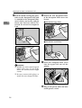
1. Replacing Consumables
and Maintenance Kit
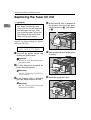
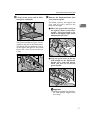
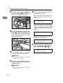
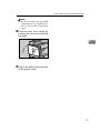
Detaching the SR770 (2 Tray Finisher)
There are times when you might have
to detach the 2 Tray Finisher from the
printer to remove misfed paper. This
section describes how to detach the 2
Tray Finisher.
A Hold the handle at the top of the 2
Important
❒ Be sure to attach the 2 Tray Finisher to the printer after closing
the Duplex Reversal Unit. See
P.2 “Opening and Closing the Duplex Reversal Unit”.
Tray Finisher firmly with one
hand, pull the 2 Tray Finisher
straight out, and let go when it
stops.
ZDJP201J
The 2 Tray Finisher is detached
from the printer.
B Use both hands to push it straight
back in, and let go when it clicks
into place.
ZDJP202J
The 2 Tray Finisher is reattached to
the printer.
1
Replacing Consumables and Maintenance Kit
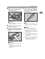
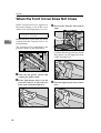
Opening and Closing the Duplex Reversal
Unit
1
There are times when you might have
to detach the Duplex Reversal Unit to
remove misfed paper. This section
describes how to detach the Duplex
Reversal Unit.
A Push up the lock release button
and keep it in place.
Note
❒ You do not have to remove the
External Tray even if the 2 Tray
Finisher is attached.
The D u plex Reve rsal U n it is
opened.
C Raise
the Duplex Reversal Unit
slowly with both hands, and push
it in until it clicks into place.
ZDJP203J
B Lower the Duplex Reversal Unit
slowly until it stops.
ZDJP205J
The D u plex Reve rsal U n it is
closed.
Important
❒ Attach the Duplex Reversal
Unit after closing the upper left
cover of the printer.
ZDJP204J
Important
❒ Open the Duplex Reversal Unit
after detaching the 2 Tray Finisher from the printer. See P.1
“Detaching the SR770 (2 Tray
Finisher)”.
2
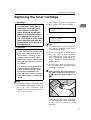
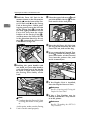
Replacing the Toner Cartridge
Replacing the Toner Cartridge
R WARNING:
• Do not incinerate spilled toner
or used toner. Toner dust is
flammable and might ignite
when exposed to an open
flame. Disposal should take
place at an authorized dealer
or an appropriate collection
site. If you dispose of the used
toner cartridges yourself, dispose of them according to local regulations.
R CAUTION:
• The inside of the machine becomes very hot. Do not touch the
parts with a label indicating a
"hot surface". Touching a "hot
surface" could result in a burn.
• Keep toner (used or unused) and
the toner cartridge out of reach
of children.
• Our products are engineered to
meet the highest standards of
quality and functionality. When
purchasing expendable supplies, we recommend using only
those provided by an authorized
dealer.
If "Add Toner" appears on the panel
display, replace the toner cartridge.
1
Add Toner
XXX
or
Add Toner
XXX/XXX
Note
❒ A combination of one to four colors, yellow, magenta, cyan, black,
is displayed in "XXX".
❒ If cyan or magenta or yellow toner
runs out, you can print in black
and white mode using the black
toner. Change the color mode setting to "Black and White" from the
printer driver .
❒ If black toner runs out, printing is
not possible until the black toner
cartridge is replaced.
A While pushing the lock button on
the upper right cover of the printer (A
A), open the upper right cover
(B
B).
Note
❒ The actual number of printed pages will differ depending on the paper type, size, contents and
settings. For more information, see
P.50 “Toner cartridge”.
ZDJT006J
From the end, the toner cartridges
are installed in the order of magenta (M), cyan (C), yellow (Y), and
black (K).
3
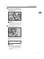
Replacing Consumables and Maintenance Kit
B Remove
the toner cartridge for
the color you want to replace.
A Unhook the green hook on the
toner cartridge with one hand.
1
Note
❒ The black toner cartridge contains more than the other toner
cartridges.
D Shake
the toner cartridge back
and forth 5-6 times.
ZDJT999J
B Holding the toner cartridge
with the other hand, pull out
the cartridge up slowly.
ZDJT203J
E Holding the toner cartridge with
the metal contact area in front, attach in the direction of the arrow.
ZDJT201J
Important
❒ Do not shake the removed
toner cartridge. The remaining toner might scatter.
C Take
out a new toner cartridge
from the box.
ZDJT202J
4
ZDJT004J
Important
❒ Do not touch the metal contact
point with your fingers.
Replacing the Toner Cartridge
F Insert the toner cartridge slowly
until the green hook snaps on the
metal contact area.
1
ZDJT005J
Important
❒ Do not install and remove the
toner cartridges over and over.
This could result in a toner leak.
G Close the upper right cover.
ZDJH042J
The following message appears on
the panel display. Please wait a
while.
Loading Toner...
Important
❒ Do not turn off the power
switch during "Loading Toner..." appears on the panel display to avoid a printer
malfunction.
5
Replacing Consumables and Maintenance Kit
Replacing the Fuser Oil Unit
R CAUTION:
• The Fusing Unit becomes very
hot. When installing the new
Fuser Oil Unit, turn off the printer
and wait about an hour. After
that, install the new Fusing Unit.
Not waiting for the unit to cool
down can result in a burn.
1
D If the External Tray is attached to
the printer, raise it in the direction of the arrow (A
A), and remove
it (B
B).
If "Replace Fuser Oil Unit (TypeG)"
appears on the panel display, replace
the Fuser Oil Unit.
Replace Fuser
Oil Unit (TypeG)
A Turn
off the power switch and
unplug the power cable.
ZDJP038J
E Pull out the left cover of the printer slowly.
Important
❒ Be sure to wait about an hour to
prevent a burn.
B If 2 Tray Finisher is installed, detach it from the printer.
Reference
See P.1 “Detaching the SR770 (2
Tray Finisher)”
C If
the Duplex Unit is installed,
open the Duplex Reversal Unit.
ZDJH047J
F Open the upper left cover.
Reference
See P.2 “Opening and Closing the
Duplex Reversal Unit”
ZDJH048J
6
Replacing the Fuser Oil Unit
G Holding
the green handle, pull
up the Fusing Unit slowly in the
direction of the arrow.
J Take out the Fuser Oil Unit from
the bag, and remove seal (A
A), and
then remove seal (B
B) as shown in
the illustration.
1
ZDJH208J
ZDJH053J
Important
❒ Do not touch any areas other
than the handle.
H Put the removed Fusing Unit in a
stable and level place.
I Lift the Fuser Oil Unit in the di-
rection of the arrow to remove it,
and put it in a stable and level
place.
Note
❒ Be sure to remove seal (A), and
then pull it out in a level manner.
Important
❒ Be sure to remove the seals to
avoid printer malfunction.
❒ Be sure to remove seal (A) first,
and then remove seal (B) to
avoid oil leak.
❒ Be sure to put the Fuser Oil Unit
in a stable and level place to
avoid oil leak.
❒ There is oil on the removed
seals and fuser oil roller. Be
careful not to let them come in
contact with your clothes.
ZDJH052E
Important
❒ Do not touch inside of the Fusing Unit.
❒ Be careful no to touch the area
other than the shown in the illustration.
7
Replacing Consumables and Maintenance Kit
K Hold
the Fuser Oil Unit in the
manner shown in the illustration.
Match (U
U) on the front of the Fuser Oil Unit and (T
T) on the Fusing
Unit at three places. While pushing the green lever on the left side
of the Fusing Unit (A
A), insert the
left and right protrusions of the
Fuser Oil Unit into the white
holders of the Fusing Unit (B
B ),
and then move the Fuser Oil Unit
in the direction shown by the arrow (C
C ) to attach the Fuser Oil
Unit to the Fusing Unit.
1
A) and
M Close the upper left cover (A
push the handle slowly (B
B) to the
back until it clicks into place.
ZDJH051J
N Place the old Fuser Oil Unit into
the bag which contained the new
Fuser Oil Unit, and seal the bag.
O If you removed the External Tray
in step D, reattach it to the printer.
Insert the hooks of the External
Tray into the printer slits, and
lower it toward you.
ZDJH054E
L Holding
the green handle with
one hand, use your other hand to
push the front area of the handle
to create a slight slant, and push
the Fusing Unit slowly to the
back.
ZDJH010J
P If
the Duplex Unit is installed,
close the Duplex Reversal Unit.
Reference
See P.2 “Opening and Closing the
Duplex Reversal Unit”
ZDJH050E
Note
❒ Confirm that the Fuser Oil Unit
is facing the inside of the printer.
8
At this point, make sure the Fusing
Unit is on the stand properly.
Q If
the 2 Tray Finisher was installed, reattach the 2 Tray Finisher to the printer.
Reference
See P.1 “Detaching the SR770 (2
Tray Finisher)”
Replacing the Fuser Oil Unit
R Plug in the power cable and turn
on the power switch.
Note
❒ If you dispose of the used toner
cartridges by yourself, dispose
of them according to local regulations.
1
9
Replacing Consumables and Maintenance Kit
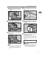
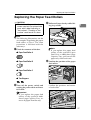
Replacing the Photoconductor Unit
If "Replace Black PCU (Type F)" appears on the panel display, replace
the black Photoconductor Unit.
1
D Turn the light brown lever counterclockwise.
Replace Black
PCU (Type F)
If "Replace Color PCU (Type A)" appears on the panel display, replace
the three color Photoconductor Units.
Replace Color
PCU (Type A)
ZDJH014E
A Turn
off the power switch and
unplug the power cable.
B Open
E Loosen two screws that are fastening the inner cover using provided screwdriver.
the front cover slowly by
pulling down from the two areas
on the left and right.
ZDJH015J
You cannot remove these two
screws.
ZDJH007J
C Take out the green screwdriver.
Use this screwdriver for all attachment and detachment of screws.
ZDJH013J
10
Replacing the Photoconductor Unit
F Lift the inner cover until it clicks
into place and holds.
G Remove the Photoconductor Unit
you want to replace.
For black, remove the upper left
one, and for color, remove the
three on the right.
A Move the green hook slowly to
the right as shown in the illustration. The green hook is located on the upper right of the
Photoconductor Unit.
1
ZDJH016J
The Photoconductor Units are installed as shown in the illustration.
The black Photoconductor Unit is
at the upper left period. The other
three are color Photoconductor
Units.
ZDJX701J
B Grip the green areas at the top
and bottom of the Photoconductor Unit, and pull slowly
until you can see all of the
green handle.
ZDJH045J
ZDJH211J
Important
❒ Pulling out the Photoconductor Unit quickly might cause
it to drop.
11
Replacing Consumables and Maintenance Kit
C Lift and hold the green handle
at the top (A
A), and pull out the
unit slowly (B
B).
C Match the green arrow at the
tip of the Photoconductor Unit
to the rail inside the printer.
1
ZDJH210J
H Install a new Photoconductor Unit.
For black, install one, and for color,
install three.
A Take the unit out from the bag.
ZDJH223J
Important
❒ Make sure the green arrow
fits securely on the rail before
proceeding to the next step.
D Push the front of the Photoconductor Unit slowly with your
right hand, slide the unit on
the cover, and push in until it
stops.
ZDJH221J
Important
❒ Do not remove the cover that is
attached to the bottom of the Photoconductor Unit at this time.
B Place the Photoconductor Unit in
your left hand, and remove the adhesive tape at the tip of the unit.
ZDJH224J
Important
❒ If you do not attach the green
arrow of the Photoconductor
Unit securely to the rail, you
might damage the Photoconductor Unit.
❒ Do not touch the light-sensitive area of the Photoconductor Unit.
ZDJH222J
12
Replacing the Photoconductor Unit
E Remove the cover and push in
the Photoconductor Unit until
it stops.
K Turn the light brown lever clockwise.
1
ZDJH020E
ZDJX702E
I Lower the inner cover slowly.
L Close
the front cover slowly by
pushing the two areas on the left
and right.
ZDJH018J
J Tighten two screws using provided screwdriver.
ZDJH041J
M Plug in the power cable and turn
on the power switch.
The following message appears on
the panel display. The printer
starts calibration. Please wait until
it stops.
Calibrating...
ZDJH019J
Note
❒ Be sure to return the provided
screwdriver to its original position on the back of the front cover.
Important
❒ Do not turn off the power
switch during calibration to
avoid a printer malfunction.
13
Replacing Consumables and Maintenance Kit
Replacing the Development Unit
If "Replace Black Dev. Unit(TypeD)"
appears on the panel display, replace
the black Development Unit.
1
C Take out the green screwdriver.
Use this screwdriver for all attachment and detachment of screws.
Replace Black
Dev. Unit(TypeD)
If "Replace Color Dev. Unit(TypeB)"
appears on the panel display, replace
the three color (CMY) Development
Units.
Replace Color
Dev. Unit(TypeB)
Note
❒ A dustproof filter is attached to the
black Development Unit. When
replacing the black Development
Unit, also replace the dustproof filter. See P.23 “Replacing the Dustproof Filter”.
ZDJH013J
D Turn the light brown lever counterclockwise.
❒ When replacing the black Development Unit, clean the registration
roller. See P.32 “Cleaning the Registration Roller”.
A Turn
ZDJH014E
off the power switch and
unplug the power cable.
B Open
the front cover slowly by
pulling down from the two areas
on the left and right.
E Loosen two screws that are fastening the inner cover using provided screwdriver.
ZDJH015J
ZDJH007J
14
You cannot remove these two
screws.
Replacing the Development Unit
F Lift the inner cover until it clicks
into place and holds.
Important
❒ Pulling out the Development
Unit quickly might cause it to
drop.
1
B Hold the right side of the Development Unit with your
right hand, and pull out the
unit slowly.
ZDJH016J
The Development Unit is installed
shown in the illustration. Starting
from the upper left, the units are
attached in the order of black (K),
yellow (Y), cyan (C), and magenta
(M).
ZDJH993J
Important
❒ Be careful not to touch the
right side of the Photoconductor Unit.
❒ Be careful not to let it get in
contact with your hands or
clothes.
ZDJH046J
G Remove the Development Unit.
The procedure for removing the
unit is the same for all four colors.
A Hook your finger on the green
tab in front of the Development Unit you want to replace,
and pull it out halfway.
H Install a new Development Unit.
The procedure for attaching the
Development Unit is the same for
all four colors.
A Take the unit out from the bag.
ZDJH226J
ZDJH225J
15
Replacing Consumables and Maintenance Kit
B Insert the Development Unit
along the rail, and push in
slowly until it stops.
I Lower the inner cover slowly.
1
ZDJH018J
ZDJH227J
C Holding the Development
Unit, pull out the tape slowly
in a level manner.
J Tighten two screws using provided screwdriver.
ZDJH019J
ZDJH039J
Important
❒ Be sure to pull out the tape to
avoid printer malfunction
during operation.
❒ The removed tape is dirty.
Be careful not to let it get in
contact with your hands or
clothes.
Note
❒ Be sure to return the provided
screwdriver to its original position on the inside of the front
cover.
K Turn the light brown lever clockwise.
ZDJH020E
16
Replacing the Development Unit
L Close
the front cover slowly by
pushing the two areas on the left
and right.
1
ZDJH041J
M Plug in the power cable and turn
on the power switch.
"Please Wait " appears on the panel
display, and initial adjustments
begin. Please wait until it stops.
Please Wait
Important
❒ Do not turn off the power
switch during adjustments to
avoid a printer malfunction.
17
Replacing Consumables and Maintenance Kit
Replacing the Fusing Unit
R CAUTION:
• The Fusing Unit becomes very
hot. When installing the new
Fusing Unit, turn off the printer
and wait about an hour. After
that, install the new Fusing Unit.
Not waiting for the unit to cool
down can result in a burn.
1
D If the External Tray is attached to
the printer, raise it in the direction of the arrow (A
A), and remove
it (B
B).
If "Replace Fusing Unit (Type C)" appears on the panel display, replace
the Fusing Unit.
Replace Fusing
Unit (Type C)
A Turn
off the power switch and
unplug the power cable.
ZDJP038J
E Pull out the left cover of the printer.
Important
❒ Be sure to wait about an hour to
prevent a burn.
B If the 2 Tray Finisher is installed,
detach it from the printer.
Reference
See P.1 “Detaching the SR770 (2
Tray Finisher)”
C If
the Duplex Unit is installed,
open the Duplex Reversal Unit.
ZDJH047J
F Open the upper left cover.
Reference
See P.2 “Opening and Closing the
Duplex Reversal Unit”
ZDJH048J
Important
❒ Do not touch any areas other
than the handle.
18
Replacing the Fusing Unit
G Holding
the green handle, pull
up the Fusing Unit slowly in the
direction of the arrow, and then
put it in a stable and level place.
ZDJH208J
H Take
out the new Fusing Unit
from the bag and put it in a stable
and level place.
J Attach
the Fuser Oil Unit removed in step I to the new Fusing Unit. Hold the Fuser Oil Unit
in the manner shown in the illustration. Match (U
U) on the front of
the Fuser Oil Unit and (T
T) on the
Fusing Unit at three places. While
pushing the green lever on the
left side of the Fusing Unit (A
A),
insert the left and right protrusions of the Fuser Oil Unit into
the white holders of the Fusing
Unit (B
B), and move the Fuser Oil
Unit in the direction shown by
the arrow (C
C) to attach the Fuser
Oil Unit to the Fusing Unit.
Important
❒ Be careful not to get oil on the
metal part of the left side of the
Fuser Oil Unit
Important
❒ The A3 paper which comes with
the new Fusing Unit will be
used in a later step S, so be careful not to lose it.
K Put the removed Fuser Oil Unit in
I Remove the Fuser Oil Unit in the
L Holding the green handle of the
direction of the arrow.
1
the bag that enclosed the new
Fusing Unit, and then seal it.
new Fusing Unit, use your other
hand to push the area right in
front of the handle to create a
slight slant, and then push the
Fusing Unit slowly to the back.
ZDJH052E
Important
❒ Do not touch inside of the Fusing Unit.
❒ Be careful not to touch the oil.
ZDJH050E
Important
❒ Confirm that the Fuser Oil Unit
is facing the inside of the printer.
❒ Confirm that the Fusing Unit is
properly positioned in the machine.
19
Replacing Consumables and Maintenance Kit
A) and
M Close the upper left cover (A
push the handle (B
B) slowly to the
back until it clicks into place.
1
Q Plug in the power cable and turn
on the power switch.
The following message appears on
the panel display. Please wait for a
while.
Please Wait
ZDJH051J
N If you removed the External Tray
in step D, reattach it to the printer.
Insert the hooks of the External
Tray into the printer slits, and
lower it toward you.
The following message appears on
the panel display, and the printer
starts color registration adjustment
automatically. Please wait for a
while.
Calibrating...
After finishing adjustment, the following message appears.
Initializing...
Please Wait
R Confirm that the following message is displayed on the panel display, and then press {Enter}
}.
ZDJH010J
O If
the Duplex Unit is installed,
close the Duplex Reversal Unit.
Reference
See P.2 “Opening and Closing the
Duplex Reversal Unit”
P If
the 2 Tray Finisher was installed, reattach the 2 Tray Finisher to the printer.
Reference
See P.1 “Detaching the SR770 (2
Tray Finisher)”
20
Press # for
Fuser Adjust
Replacing the Fusing Unit
S Confirm that the following message is displayed on the panel display, and then load the A3 paper
which comes with the Fusing
Unit in the Bypass Tray.
D Adjust the side guides to the
paper width.
1
Set Sheet in
Bypass, then #
A Open the Bypass Tray.
ZDJH205J
Important
❒ Be sure to shuffle the paper
before loading the stack onto
the tray so multiple sheets
are not fed in at one time.
ZDJH202J
B Pull out the Bypass Tray Extension, and then flip it open.
T Confirm that the A3 paper which
comes with the Fusing Unit is in
the Bypass Tray, and then press
{Enter}
}.
The printer prints 8 Test Sheet (A H). For details about Test Sheet,
see P.40 “Test Sheet Samples”.
ZDJH203J
C Slide the side guides outward
(A
A), and then load paper until
it stops with the print side up
(B
B).
Note
❒ It takes about a minute to start
printing.
ZDJH204J
21
Replacing Consumables and Maintenance Kit
U Check the test sheets and select
the correction value for A through
H.
• Select "1", if black and magenta
square overlap sharply and
you can see white slits as the
sample.
• Select "0", if black and magenta
square do not overlap sharply
and you can not see white slits
clearly.
1
A B C D E F G H
0 0 0 0 0 0 0 0
Press {U
U} or {T
T} to select "0" or "1"
as the values for A - H. Press {Enter} to move to the next letter. After
setting the value for "H", press {Enter}, and the printer returns to the
ready condition.
Ready
Important
❒ If you select "0" for each alphabets or an invalid value is selected, an error message is
displayed. In this case, press
{Enter} to return to the ready
condition, and perform the
"Fuser Adjust" manually. See
P.35 “When replacing the fusing
unit”.
Invalid Value
Press #
❒ When "Toner is Almost Empty"
appears on the panel display,
replace the toner cartridge and
perform the "Auto Adjust", and
then perform "Fuser Adjust"
manually.
22
Reference
⇒ P.3 “Replacing the Toner Cartridge”
⇒ P.34 “Auto Adjust”
⇒ P.35 “When replacing the fusing unit”for "Fuser Adjust"
Replacing the Dustproof Filter
Replacing the Dustproof Filter
The dustproof filter is attached to the
black Development Unit. When replacing the black Development Unit,
also replace the dustproof filter.
The dustproof filter is attached to the
left side of the printer shown in the illustration.
C From the box which contained the
1
black Development Unit, take out
the new dustproof filter and
glove.
ZDJH214J
D Wear the glove on either hand.
ZDJH801J
A Turn
off the power switch and
unplug the power cable.
B Push in the grips on both sides of
the dustproof filter cover to pull it
off.
ZDJH212J
Note
❒ Be sure to put the removed
dustproof filter cover in a stable
and level place.
23
Replacing Consumables and Maintenance Kit
E With the hand wearing the glove,
take out the dustproof filter that
is attached to the dustproof filter
cover slowly, one by one, and put
them into the box which contained the black Development
Unit.
1
F Attach the new dustproof filters
to the dustproof filter cover one
by one.
A Attach the large filter.
ZDJH216J
B Attach the small filter.
ZDJH213J
ZDJH217J
ZDJH215J
Important
❒ Handle the removed dustproof
filters with care. If you shake
them, the attached dust might
scatter.
G Insert
the dustproof filter cover
into the upper left area of the
printer.
❒ Be sure to remove the gloves to
attach the new dustproof filter.
ZDJH218J
H Plug in the power cable and turn
on the power switch.
24
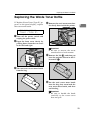
Replacing the Waste Toner Bottle
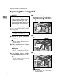
Replacing the Waste Toner Bottle
If "Replace Waste Toner (Type E)" appears on the panel display, replace
the waste toner bottle.
D Remove the used waste toner bot-
1
tle slowly from inside the printer.
Replace Waste
Toner (Type E)
A Turn
off the power switch and
unplug the power cable.
B Open
the front cover slowly by
pulling down from the two areas
on the left and right.
ZDJH802J
Important
❒ Be sure to remove the waste
toner bottle in a level manner.
A), and then put
E Remove the lid (A
it on the position shown in the illustration (B
B).
ZDJH007J
C Take out a new waste toner bottle
from the bag.
ZDJH229J
F Put
the used waste toner bottle
into the bag that contained the
new waste toner bottle, and then
seal the bag.
ZDJH228J
Important
❒ Be sure to handle the bottle
carefully so the waste toner
does not spill.
25
Replacing Consumables and Maintenance Kit
G Insert the new waste toner bottle
in the position shown in the illustration.
1
ZDJH230J
H Push it in until it stops.
ZDJH231J
Important
❒ Be sure to insert the waste toner
bottle firmly to avoid the toner
from leaking inside the printer.
I Close
the front cover slowly by
pushing the two areas on the left
and right.
ZDJH041J
26
J Plug in the power cable and turn
on the power switch.
Replacing the Paper Feed Rollers
Replacing the Paper Feed Rollers
R CAUTION:
• The inside of the machine becomes very hot. Do not touch the
parts with a label indicating a
"hot surface". Touching a "hot
surface" could result in a burn.
C Pull out all trays slowly while lift-
Note
❒ The following illustrations are the
an examples of replacing the paper
feed rollers of Tray 1. The same
procedure is followed with the
other trays.
A Check the contents of the box.
❖ Paper Feed Roller A
❖ Paper Feed Roller B
1
ing it up a little.
ZERH010E
Note
❒ If you replace the paper feed
rollers of the optional Paper
Feed Unit, or 2000-sheet Large
Capacity Tray, pull out all the
paper trays from each unit.
D Confirm the position of the paper
feed rollers.
❖ Paper Feed Roller C
❖ Two Stoppers
ZERH020E
B Turn
off the power switch and
unplug the power cable and interface cable.
Confirm the positions and names
of each roller.
Important
❒ If you replace the paper feed
rollers of the optional 2000sheet Large Capacity Tray, remove all paper from the tray.
ZERH030E
27
Replacing Consumables and Maintenance Kit
E While pushing the pin of the paper feed roller A outwards (A
A ),
remove the paper feed roller (B
B).
1
H Hold the new paper feed roller C
with its gear towards the shaft. Insert it into the rear shaft so that
the roller gear is meshed with the
shaft gear (A
A ). Lock the roller
with the stopper (B
B).
ZERH040E
F Remove the stopper from the paper feed roller B (A
A), and remove
the paper feed roller (B
B).
ZERH070E
I Hold the new paper feed roller B
with its gear towards the shaft. Insert it into the rear shaft so that
the roller gear is meshed with the
shaft gear (A
A ). Lock the roller
with the stopper (B
B).
ZERH050E
G Remove the stopper from the paper feed roller C (A
A), and remove
the paper feed roller (B
B).
ZERH080E
ZERH060E
28
Replacing the Paper Feed Rollers
J Hold the new paper feed roller A
with its pin towards you (A
A). Insert the roller onto the front shaft
until it clicks into place (B
B).
1
ZERH090E
K Slide all trays back into the printer slowly until it stops.
Note
❒ If you replaced the paper feed
rollers of the optional 2000sheet Large Capacity Tray, load
stocks that you removed at step
2 in the tray.
29
Replacing Consumables and Maintenance Kit
1
30
2. Clearing and Adjusting the
Printer
Cautions to Take When Cleaning
R WARNING:
• Do not remove any covers or screws other than those specified in this manual. Some parts of the machine are at a high
voltage and could give you an electric shock. Also, if the machine has laser systems, direct (or indirect) reflected eye
contact with the laser beam may cause serious eye damage.
When the machine needs to be checked, adjusted, or repaired, contact your service representative.
• Do not take apart or attempt any modifications to this machine. There is a risk of fire, electric shock, explosion or loss
of sight. If the machine has laser systems, there is a risk of
serious eye damage.
R CAUTION:
• When removing misfed paper, do not touch the fusing section because it could be very hot.
Clean the printer periodically to maintain fine printing.
Dry wipe the exterior with a soft cloth. If dry wiping is not enough, wipe with
a soft, wet cloth that is wrung out well. If you still cannot remove the stain or
grime, use a neutral detergent, then wipe over with a well-wrung wet cloth, dry
wipe, and let it dry.
Important
❒ To avoid deformation, discoloration, or cracking, do not use volatile chemicals, such as benzine and thinner, or spray insecticide on the printer.
❒ If there is dust or grime inside the printer, wipe with a clean, dry cloth.
31
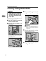
Clearing and Adjusting the Printer
Cleaning the Registration Roller
R CAUTION:
• The inside of the printer becomes very hot. Do not touch the
parts with a label indicating the
"hot surface", otherwise it could
cause a burn.
2
C Wipe around the registration roller by turning with a soft damp
cloth.
Clean the roller when replacing the
black Development Unit.
A Turn
off the power switch and
unplug the power cable.
B Open the right cover shown in the
ZDJH704J
illustration.
Important
❒ Do not use chemical cleaner or
organic solvent such as thinner
or benzene.
D Close the right cover by pushing
the area labeled "PUSH".
ZDJH206J
The registration roller is set shown
in the illustration.
ZDJP708J
E Plug in the power cable and turn
on the power switch.
ZDJH703J
32
Cleaning the DustProof Glass
Cleaning the DustProof Glass
The dustproof glass may require
cleaning if white lines appear on the
print side of the document.
A Turn
C Slide the cleaning brush in and
out slowly 8 to 10 times to clean
all four areas.
off the power switch and
unplug the power cable.
2
B Open the front cover and remove
the cleaning brush.
ZDJP707J
ZDJP705J
There are four holes for cleaning
the dustproof glass.
Important
❒ Do not insert the brush roughly,
or the printer might be damaged.
D Return the cleaning brush to its
original position.
E Plug in the power cable and turn
on the power switch.
ZDJP706J
33
Clearing and Adjusting the Printer
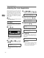
Adjusting the Color Registration
2
When the printer is moved, when the
Fusing Unit is replaced, or after printing repeatedly for some time, registration shifting might occur. By
performing color registration adjustment, you can maintain optimum
print results.
C Press {U} or {T} to display "Col-
Note
❒ Normally, do not perform manual
color adjustment.
played, and then press {Enter}
}.
Auto Adjust
If the color documents show registration shifting, perform automatic color
adjustment.
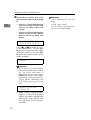
A Press {Menu}}.
or Regist.", and then press {Enter}
}.
Maintenance:
Color Regist.
D Confirm that "Auto Adjust" is disColor Regist.:
Auto Adjust
E Confirm that "Now" is displayed,
and then press {Enter}
}.
Auto Adjust:
Now
The check message is displayed.
On Line
Menu
Press #
To Adjust
Escape
#Enter
Job Reset Form Feed
Power
Error
F Press {Enter}}.
Data In
ZDJS001N
"Menu" appears on the panel display.
B Press
{U} or {T} to display
"Maintenance", and then press
{Enter}
}.
Menu:
Maintenance
The maintenance menu is displayed.
34
Automatic color adjustment begins, and the following message is
displayed.
Adjusting...
Important
❒ Do not turn off the power
switch during "Adjusting..." appears on the panel display to
avoid printer malfunction.
Adjusting the Color Registration
Automatic color adjustment takes
about two minutes. When it completes, a check message is displayed, and the display is returned
to the color adjustment menu.
Completed
Color Regist.:
Auto Adjust
G When you have made all the set-
tings, press {On Line}
}.
"Ready " appears on the panel display.
Ready
Fuser Adjust
When replacing the fusing unit
Note
❒ When "Toner is Almost Empty"
appears on the panel display, replace the toner cartridge and perform "Auto Adjust", and then
perform the "Fuser Adjust".
2
Reference
⇒ P.3 “Replacing the Toner Cartridge”
⇒ P.34 “Auto Adjust”
A Press {Menu}}.
On Line
Menu
Escape
#Enter
Job Reset Form Feed
Power
Error
Data In
ZDJS001N
"Menu" appears on the panel display.
B Press
{U} or {T} to display
"Maintenance", and then press
{Enter}
}.
Menu:
Maintenance
The maintenance menu is displayed.
C Press {U} or {T} to display "Col-
or Regist.", and then press {Enter}
}.
Maintenance:
Color Regist.
35
Clearing and Adjusting the Printer
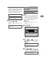
D Press {U} or {T} to display "Fus-
er Adjust", and then press {Enter}
}.
Color Regist.:
Fuser Adjust
Important
❒ When the toner cartridge is almost empty or "Auto Adjust” is
not finished, the following message appears on the panel display and Fuser Adjust is not
available.
2
Cannot Adjust
See User’s Guide
Confirm that the toner cartridge is
installed. The toner cartridge must
be installed. See P.3 “Replacing the
Toner Cartridge”.
If the toner cartridge is installed,
perform "Auto Adjust". See P.34
“Auto Adjust”.
E Press {U} or {T} to display "At
Unit Replace", and then press {Enter}
}.
Fuser Adjust:
At Unit Replace
F Confirm that "Print" is displayed
on the menu for printing the test
sheet, and then press {Enter}
}.
Test Sheet:
Print
The following message appears on
the panel display.
Set Sheet in
Bypass, then #
G Confirm that the A3 paper which
comes with the Fusing Unit is in
the Bypass Tray, and then press
{Enter}
}.
The printer prints 8 Test Sheet (A H). For details about Test Sheet,
see P.40 “Test Sheet Samples”
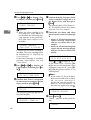
H Check the test sheets and select
the correction value for A through
H.
• Select "1", if black and magenta
square overlap sharply and
you can see white slits as the
sample.
• Select "0", if black and magenta
square do not overlap sharply
and you can not see white slits
clearly.
A B C D E F G H
0 0 0 0 0 0 0 0
Press {U
U} or {T
T} to select "0" or "1"
as the values for A - H. Press {Enter} to move to the next letter. After
setting the value for "H", press {Enter} and the printer returns to "At
Unit Replace".
Note
❒ If you select "0" for each alphabets or an invalid value is selected, an error message is
displayed and the printer returns to "At Unit Replace". In
this case, try again from step E.
Invalid Value
Cannot Adjust
I Press {On Line}}.
"Ready " appears on the panel display.
Ready
36
Adjusting the Color Registration
E Press {U} or {T} to display "Fus-
When color shifting occurs
er Adjust", and then press {Enter}
}.
Perform this procedure when color
shifting occurs even after performing
"Auto Adjust".
L or larger paper in the
A Load A4L
Bypass Tray.
Note
❒ Be sure to select paper size in
the "Paper Input" menu.
Reference
For details about paper size and
the procedure for loading paper
in the Bypass Tray, see "Loading
Paper" in Maintenance Guide 2.
B Press {Menu}}.
On Line
Menu
#Enter
Power
Error
Data In
2
Cannot Adjust
See User’s Guide
F Press {U} or {T} to display "CusZDJS001N
"Menu" appears on the panel display.
C Press
{U} or {T} to display
"Maintenance", and then press
{Enter}
}.
Menu:
Maintenance
The maintenance menu is displayed.
D Press {U} or {T} to display "Col-
or Regist.", and then press {Enter}
}.
Maintenance:
Color Regist.
Important
❒ When the toner cartridge is almost empty, or Auto Adjust is
not finished, the following message appears on the panel display and "Fuser Adjust" is not
available.
Confirm that the toner cartridge is
installed. The toner cartridge must
be installed. See P.3 “Replacing the
Toner Cartridge”.
If the toner cartridge is installed,
perform "Auto Adjust". See P.34
“Auto Adjust”.
Escape
Job Reset Form Feed
Color Regist.:
Fuser Adjust
tom Adjust", and then press {Enter}
}.
The following message appears on
the panel display.
Fuser Adjust:
Custom Adjust
G Press {U} or {T} to display the
paper types and resolution in
which color shifting occurs, and
then press {Enter}
}.
Custom Adjust:
Plain: 600dpi
Select a value from "Plain: 600dpi",
"Plain: 1200dpi" and "Thick:
600dpi".
37
Clearing and Adjusting the Printer
Note
❒ The current resolution is displayed on the printer driver
properties.
❒ To adjust the color registration
on thick paper, select "Thick:
600dpi" regardless of the current resolution.
2
H Confirm that the following message is displayed, and then press
{Enter}
}.
Press # for Test
Print (Bypass)
The following message appears on
the panel display. The size of the
paper loaded in step A is shown.
Set Sheet, then#
A3 (297 X 420)
L or larger paper
I Confirm that A4L
is in the Bypass Tray, and then
press {Enter}
}.
The Test Sheet is printed. See P.40
“Test Sheet Samples”
If you select "0: Exit", the printer returns to the previous menu.
If you select "-1" or "+1", the printer
returns to step H. Keep adjusting
until "0" is available.
K Press {On Line}}.
"Ready " appears on the panel display.
Ready
Manual Adjust
Important
❒ Normally, do not perform manual
color adjustment.
A Press {Menu}}.
On Line
Menu
Escape
#Enter
Job Reset Form Feed
Power
Error
Data In
J Press {U} or {T} to make the off-
set settings, and then press {Enter}
}.
When such a clear (not smeared in
red) square as the sample is:
• at its center position, select "0".
• shifted to the left, select "-1".
• shifted to the right, select "+1".
Select Action:
0: Exit
38
ZDJS001N
"Menu" appears on the panel display.
B Press {U} or {T} to display "Main}.
tenance", and then press {Enter}
Menu:
Maintenance
The maintenance menu is displayed.
Select Action:
-1: Re-adjust
C Press {U} or {T} to display "Col-
Select Action:
+1: Re-adjust
Maintenance:
Color Regist.
or Regist.", and then press {Enter}
}.
Adjusting the Color Registration
D Press {U} or {T} to display "Manual Adjust", and then press {Enter}
}.
Color Regist.:
Manual Adjust
E Confirm that "Print" is displayed
in the menu for printing the Test
Sheet, and then press {Enter}
}.
Test Sheet:
Print
The Test Sheet is printed. See P.40
“Test Sheet Samples”.
F Enter the corrective values for A
through L on the Test Sheet in order.
Adjustment A:
(-7.0 +7.0)
+0
Note
❒ Confirm the printed Test Sheet
to enter the correction values.
A Use {U} or {T} to enter the
value (-7.0 to +7.0) shown next
to the whitest square, into box
A of the Test Sheet.
Adjustment A:
(-7.0 +7.0)
+2
Note
❒ Pressing {U
U} or {T
T} increases or decreases the value in
0.5 units.
❒ Sometimes, there are two of
the whitest squares next to
each other. For example, if
the two squares of "+1" and
"+2" are the whitest, enter
"+1.5".
❒ You can adjust the color
alignment for each color in
the range of "-7.0 to +7.0".
❒ There is an area on the Test
Sheet for you to put down
the values of "A" through "L".
B Press {Enter}
}.
C Make the settings for "B" to "L"
in the same manner, using
steps A and B.
D When you finish the settings
up to "L", press {Enter}
} in the
next menu.
2
Manual Adjust:
Print Result
The Test Sheet is printed. See
P.40 “Test Sheet Samples”.
Printing...
E Confirm that square "0" is the
whitest within A through L on
the printed Test Sheet.
Note
❒ If a square other than "0" is
the whitest, redo the procedure from step D.
The display is returned to the
manual adjustment menu.
Color Regist.:
Manual Adjust
G When you have made all the set-
tings, press {On Line}
}.
"Ready " appears on the panel display.
Ready
39
Clearing and Adjusting the Printer
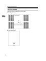
Test Sheet Samples
Following images are samples for the test sheet.
❖ ColorRegistSheet
2
❖ Fuser Adjust Sheet I
40
Adjusting the Color Registration
❖ Fuser Adjust Sheet II
2
41
Clearing and Adjusting the Printer
Adjusting the Image Density
Adjust the image density when the
print side of the page is a hazy gray or
the print image looks patchy.
Important
❒ Extreme settings may create output that appears dirty.
2
❒ Image density settings should be
made from the application or the
printer driver whenever possible.
Note
❒ Changing the image density setting might cause a deterioration of
color balance. We recommend that
you leave the image density at its
factory default setting.
A Press {Menu}}.
C Press {U} or {T} to display "Im-
age Density", and then press {Enter}
}.
Maintenance:
Image Density
D Press {U} or {T} to select the color you want to adjust, and then
press {Enter}
}.
Image Density:
Black
E Press {U} or {T} to set the image
density value, and then press {Enter}
}.
Black:
(-3 +3)
On Line
Menu
0
Escape
#Enter
Job Reset Form Feed
Power
Error
Data In
ZDJS001N
"Menu" appears on the panel display.
B Press
{U} or {T} to display
"Maintenance", and then press
{Enter}
}.
Menu:
Maintenance
42
0
Note
❒ You can adjust the image density in seven steps from -3 to +3.
Increasing the value makes the
printouts darker and decreasing
the value makes the printouts
lighter.
To adjust another color, repeat step
D and E.
F Press {On Line}}.
"Ready " appears on the panel display.
Ready
Adjusting the Registration of the Trays
Adjusting the Registration of the Trays
You can adjust the registration of
each tray. The vertical adjustment is
used for all trays. Normally, you need
not update the registration. But when
the optional Paper Feed Unit or the
Duplex Unit is installed, updating the
registration is useful in some cases.
The following procedure describes
how to adjust Tray 3. You can use the
same procedure to adjust the other
tray as well.
A Press {Menu}}.
On Line
settings.
A Confirm that "Test Sheet" is dis}.
played, and then press {Enter}
2
Registration:
Prt. Test Sheet
B Press {U} or {T} to display the
tray to adjust, then press {Enter}
}.
Prt. Test Sheet:
Tray 3
Menu
E Confirm the position of the image
to test sheet, and then adjust the
registration value.
Escape
#Enter
Job Reset Form Feed
Power
D Print the test sheet to preview the
Error
Data In
ZDJS001N
"Menu" appears on the panel display.
B Press
{U} or {T} to display
"Maintenance", and then press
{Enter}
}.
Menu:
Maintenance
C Press {U} or {T} to display "Registration", and then press {Enter}
}.
Maintenance:
Registration
The following are examples for adjusting the margin on the test sheet.
A Press {Escape}
}.
B Press {U} or {T} to display the
"Adjustment", and then press
{Enter}
}.
Registration:
Adjustment
43
Clearing and Adjusting the Printer
C Press {U} or {T} to display the
tray to adjust, and then press
{Enter}
}.
Adjustment:
Vert.: Tray 3
Vert.: Tray 3:
(-4.0 +4.0) 0
Note
❒ Increase the value to shift the
print area in a positive direction, and decrease to shift in a
negative direction.
Feed Direction
Printable area
ZDJX900J
❒ Pressing {U
U} or {T
T} makes
the value increase or decrease by 1.0 mm step.
E Press {Enter}
}.
F Press {Escape}
}.
The current setting is displayed
for 2 seconds, and then the
printer returns to the previous
menu.
F Print the test sheet to check the
settings you have made.
44
"Ready " appears on the panel display.
Ready
D Press {U} or {T} to set the digit of the registration value
(mm).
2
G Press {On Line}}.
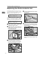
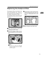
3. Appendix
Removing Misfed Paper in the Duplex
Feed Unit
You can remove misfed paper from
the Duplex Feed Unit following the
procedure below.
C Take out the green screwdriver.
Use this screwdriver for all attachment and detachment of screws.
Note
❒ When a paper misfeed occurs in
the Duplex Feed Unit, the printer
usually sends the misfed paper to
the right cover and there is no need
to execute following procedure.
See "When “Remove Misfeed A:Internal Path” Appears" in Maintenance
Guide 2.
Important
❒ Be sure to remove a misfed paper
following the procedure below,
o n ly w h en "R em ov e M i sfeed
Z2:Dup. Feed Unit" appears on the
panel display.
ZDJH013J
D Remove the screw that is fastening the Duplex Feed Unit using
provided screwdriver.
A Turn
off the power switch and
unplug the power cable.
B Open
the front cover slowly by
pulling down from the two areas
on the left and right.
ZDJP221J
You will use this screw to refasten
the Duplex Feed Unit later.
ZDJH007J
45
Appendix
E Pinch the upper left area of the
Duplex Feed Unit, and pull it out
slowly halfway.
H Close the Duplex Feed Unit.
I Holding the Duplex Feed Unit
with both hands, insert it along
the rails slowly until it stops.
3
ZDJP213J
F Holding
the Duplex Feed Unit
firmly with both hands, pull it
straight out.
ZDJP056J
The top and bottom rails are located in the position shown in the illustration.
ZDJP214J
G Place the Duplex Feed Unit on the
floor slowly. Open it slowly, and
remove the misfed paper.
ZDJP133J
There are two arrows located on
the left and right sides of the Duplex Feed Unit.
J Refasten
the Duplex Feed Unit
using provided screwdriver. Use
the screw that was removed in
step D.
ZDJP215J
Important
❒ Do not open the Duplex Feed
Unit by force. It might damage
the unit.
46
ZDJP057J
Removing Misfed Paper in the Duplex Feed Unit
Note
❒ Be sure to return the provided
screwdriver to its original position on the inside of the front
cover.
K Close
the front cover slowly by
pushing the two areas on the left
and right.
3
ZDJH041J
L Plug in the power cable and turn
on the power switch.
47
Appendix
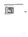
When the Front Cover Does Not Close
When "Close Front Cover" appears on
the panel display, even if the cover
seems to be closed properly, it is not.
C Push in the Transfer Unit until it
stops.
Close
Front Cover
When the front cover does not close,
confirm that the Transfer Unit is attached firmly.
The Transfer Unit is attached to the
position shown in the illustration.
3
ZDJH999J
Confirm that the protrusion inside
the printer is in the upper left hole
of the Transfer Unit.
ZDJH995J
A Turn
off the power switch and
unplug the power cable.
B If the light brown lever is in the
position shown in the illustration, turn it counterclockwise.
ZDJH992J
D Turn the light brown lever clockwise.
ZDJH014E
ZDJH020E
48
When the Front Cover Does Not Close
E Close
the front cover slowly by
pushing the two areas on the left
and right.
3
ZDJH041J
F Plug in the power cable and turn
on the power switch.
49
Appendix
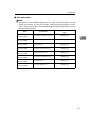
Consumables
R CAUTION:
• Our products are engineered to meet the highest standards of quality and
functionality. When purchasing expendable supplies, we recommend using
only those specified by an authorized dealer.
❖ Toner cartridge
Toner cartridge
3
Average printable number of pages per cartridge *1
Cyan
10,000 pages
Magenta
10,000 pages
Yellow
10,000 pages
Black
20,000 pages
*1
A4 5% test chart
Note
❒ The actual number of printed pages you get from a particular toner cartridge depends on the type and size of paper you are using, the contents of
your print images, and printing environment conditions. All this means
that a toner cartridge might require replacement sooner than the normal
life described above.
❒ Toner cartridges that come with the printer are for setup purposes, and
will not provide the number of pages described above. The average number of printable pages that can be expected from the toner cartridges included in the printer are as follows:
• Black toner cartridge : about 10,000 pages
• Cyan, magenta and yellow toner cartridges : about 5,000 pages for each
cartridge.
❖ Staple Cartridge
Cartridge type
Staple cartridge
Staple Refill cartridge
50
Number of shots
5000 shots × 1 with cartridge
Refill 5000 shots × 3
Consumables
❖ Other consumables
Note
❒ Actual life of consumables depends on the type and size of paper you are
using, the contents of your print images, and printing environment conditions. All that means that consumables might require replacement sooner
than the life indicated.
Consumables
Average printable number of
pages
Printer Maintenance
Kit Type 3800A
Color Photoconductor Unit × 3
100,000 pages
Printer Maintenance
Kit Type 3800B
Color Development Unit × 3
150,000 pages
Printer Maintenance
Kit Type 3800C
Fusing Unit × 1
100,000 pages
Printer Maintenance
Kit Type 3800D
Black Development Unit × 1
150,000 pages
Printer Maintenance
Kit Type 3800E
Waste Toner Bottle × 1
50,000 pages
Printer Maintenance
Kit Type 3800F
Black Photoconductor Unit × 1
150,000 pages
Printer Maintenance
Kit Type 3800G
Fuser Oil Unit × 1
20,000 pages
Printer Maintenance
Kit Type 3800H
Paper Feed Rollers × 1
150,000 pages
Name
3
51
Appendix
Paper Recommendations
Loading Paper
Important
❒ Do not use paper that is meant for an ink-jet printer or it may stick to the Fusing Unit and cause a paper misfeed.
❒ When printing on an OHP transparency that has a print side, load it with the
print side over on the Bypass Tray. Not taking this precaution may cause it to
stick to the Fusing Unit and cause a misfeed.
❒ Print quality cannot be guaranteed if recommended paper is not used. For details about recommended paper, contact your sales or service representative.
❒ Do not use paper that has already been printed onto by other printers.
3
Storing Paper
• Paper should always be stored properly. Improperly stored paper might result in poor print quality, paper misfeeds, or printer damage. Recommendations are as follows:
• Avoid storing paper in humid areas.
• Avoid exposing paper to direct sunlight.
• Store on a flat surface.
• Keep open reams of paper in the package in which the paper came.
Types of Paper and Other Media
❖ Plain Paper
• Tray 1/2 can hold up to 500 sheets.
PAPER FEED UNIT Type 3800C (500x1) can hold up to 500 sheets.
PAPER FEED UNIT Type 3800C (500x2) can hold up to 1000 sheets.
Paper Bank PS470 can hold up to 2000 sheets.
Confirm that the top of the stack is not higher than the limit mark inside
the tray.
• Bypass Tray supports custom size, approximately 3.5 - 12 inch in width,
and approximately 5.8 - 18 inch in length.
• When printing on the reverse side of plain paper that is already printed on,
you should load it on the Bypass Tray and select [Plain (Duplex Backside)]
from [Paper Type:] with the printer driver.
52
Paper Recommendations
❖ Thick Paper
• Use the Bypass Tray.
• The Bypass Tray can hold paper up to 135 kg (163 g/m2) in weight. The
print quality on paper that is thicker cannot be guaranteed.
• Confirm that the top of the stack is not higher than the limit mark inside
the tray.
• When printing on thick paper, select thick paper mode with the printer
driver.
• When printing on the reverse side of plain paper that is already printed on,
you should load it on the Bypass Tray and select [Thick (Duplex Backside)]
from [Paper Type:] with the printer driver.
3
Note
❒ The number of sheets to be set may vary depending on the paper thickness and paper type.
❖ OHP transparencies
• When printing on OHP transparencies, use the Bypass Tray.
• Load OHP transparencies on the tray with the print side over or they may
stick to the Fusing Unit and cause a misfeed.
• Remove any unused OHP transparencies from the Bypass Tray after you
are finished printing. Leaving them in the tray may cause them to stick together.
• When printing on OHP transparencies, you should select the OHP transparency mode with the printer driver.
• The Bypass Tray can hold up to 100 OHP transparency sheets.
• Confirm that the top of the stack is not higher than the limit mark inside
the tray.
• When you print OHP transparencies more than one copies, remove each
sheet from the tray one by one before next sheet is printed out, or select
"Slip Sheet" in the printer driver. For details about using "Slip Sheet", see
the printer driver Help file.
53
Appendix
❖ Envelopes
• When printing on envelopes, use the Bypass Tray.
• Specifications of envelopes are as follows:
Metric version
Weight
Recommended weight
and size
72 - 90 g/m
72 g/m
2
114 × 162 mm
(C6 Env)
2,
Inch version
19 - 24 lb
24 lb, 37/8" × 71/2"
(Monarch)
• You can load up to 10 envelopes (72 - 92 g/m2, 19 - 24 lb) in the Bypass Tray at the
same time, without forcibly pressing them. Confirm that the envelopes are not damp,
and that the top of the stack is n\ot higher than the limit mark on the side guide.
• Confirm that the print side is facing up when loading onto the Bypass Tray.
• Load the envelopes with the flaps aligned to the left side fence. The flaps
should be securely folded up.
• Confirm that there is no air in the envelopes before loading.
• To get better print quality, it is recommended that you set the right, left,
top, and bottom print margin, to at least 15 mm (0.6") each.
• Do not print on both sides of envelopes.
• Load only one size and type of envelopes at the same time.
• Before loading envelopes, flatten the leading edges (the side being fed into
the printer) of them by running a pencil or ruler across them.
• Before loading envelopes, confirm that they are rectangular in shape.
• Supported size of envelope is listed on "Paper and Other Media" in Maintenance Guide 2.
3
54
❖ Paper not supported by this printer
Avoid using the following types of paper that are not supported by this printer:
• Paper meant for an ink-jet printer
• Bent, folded, or creased paper
• Curled or twisted paper
• Torn paper
• Wrinkled paper
• Damp paper
• Paper that is dry enough to emit static electricity
• Paper that has already been printed onto, except a preprinted letterhead
• Coated paper
• Special paper, such as thermal paper, aluminum foil, carbon paper and
conductive paper
• Paper whose weight is heavier or lighter than the limitation.
• With windows, holes, perforations, cutouts, or embossing
• Label paper on which glue or base paper is exposed
• Paper with clips or staples
Paper Recommendations
Printable Area
The following shows the printable area for this printer. Be sure to set the print
margins correctly by the application.
4.2mm (0.166 inch)
Feed Direction
4.2mm (0.166 inch)
4.2mm (0.166 inch)
3
4.2mm (0.166 inch)
A
: printable area
Note
❒ The printable area may vary depending on the paper size, printer language
and printer driver settings.
55
INDEX
A
Adjusting the Color Registration, 34
Auto Adjust, 34
Manual Adjust, 38
Adjusting the Image Density, 42
Adjusting the Registration of the Trays, 43
Appendix, 45
C
Caution, ii
Cleaning the DustProof Glass, 33
Cleaning the Registration Roller, 32
Clearing and Adjusting the Printer, 31
Color Adjustment
Checking the Test Sheet, 40
Consumables, 50
D
Detaching the SR770 (2 Tray Finisher), 1
E
Energy Star, iv
Envelopes, 54
R
Removing Misfed Paper into
the Duplex Feed Unit, 45
Replacing Consumables and Maintenance Kit, 1
Replacing the Development Unit, 14
Replacing the Dustproof Filter, 23
Replacing the Fuser Oil Unit, 6
Replacing the Fusing Unit, 18
Replacing the Photoconductor Unit, 10
Replacing the Toner Cartridge, 3
Replacing the Waste Toner Bottle, 25
S
Storing Paper, 52
T
Thick Paper, 53
Toner Cartridge, 50
W
Warning, ii
When the Front Cover Does Not Close, 48
L
Loading Paper, 52
O
OHP transparencies, 53
Opening and Closing
the Duplex Reversal Unit, 2
P
Plain Paper, 52
Printable Area, 55
56
UE
USA G060
Copyright © 2001
UE USA G060-6920