1
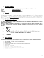
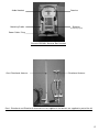
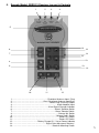
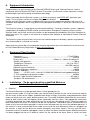
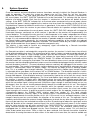
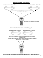
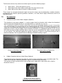
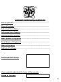
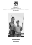
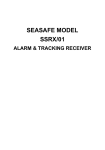
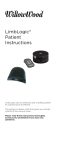
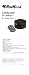
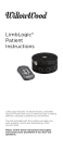
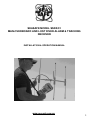
SEASAFE MODEL SSRX/01
MAN-OVERBOARD AND LOST DIVER ALARM & TRACKING
RECEIVER
INSTALLATION & OPERATION MANUAL
www.sea-safe.com.au
1
Seasafe SSRX/01 Receiver User Manual
Contents
1.
2.
3.
4.
5.
6.
7.
8.
8.a
8.b
8.c
8.d
9.
10.
11.
12.
13.
Technical support
Warranty
Regulatory compliance
Box contents
Receiver Layout and Controls
Equipment introduction
Equipment specification
Installation
Receiver
Power/auxiliary output cable
Omni-directional antenna
Collapsible directional-antenna
System operation
Signal tracking procedure
Accessories
Copyright
Warranty registration
Page
3
3
3
3/4
5
6
6
6
6
7
8
8
9/10
11
12
13
14
2
1. Technical Support
For any technical questions or for support, please contact your local Seasafe distributor or visit:
Internet:
www.sea-safe.com.au
Email:
[email protected]
Telephone:
+61 7 3488 2622
2. Warranty
Seasafe warrants this product to be free from defects in materials and workmanship for 12 months after the
date of purchase. If your Seasafe Receiver is found to be defective within that time, we will promptly repair or
replace it. This warranty does not cover accidental damage, wear and tear, or consequential or incidental loss.
Warranty registration at www.sea-safe.com.au
3. Regulatory Compliance
This device complies with AS 4268.2 as amended by LIPD (Low Interference Potential Device) 24 August
2005. In particular table ZZ1.
Operation is subject to the following two conditions: (1) This device may not cause harmful interference, and (2)
This device must accept any interference received, including any interference that may cause undesired
operation.
a.
b.
N15546
1999/5/EC ( ETSI EN 300 220-2, ETSI EN 300 220-1, ETSI EN 301 489-1,
ETSI EN 301 489-3, EN 61000-3-2, EN 6100-3-3)
c.
AS 4268.2
4. Box Contents
Included in the purchase of the Seasafe SSRX/01 Alarm & Tracking Receiver are the following components:
♦
♦
♦
♦
♦
♦
♦
♦
Seasafe Model: SSRX/01 Alarm & Tracking Receiver
Mounting cradle
5 x NiMH rechargeable batteries (installed by dealer upon purchase)
Audio headset
Power cable & connector
Marine omni-directional antenna (not in box)
Portable collapsible directional antenna (not in box)
Instruction manual
3
Audio Headset
Receiver
Mounting Cradle
Batteries
(Installed by agent)
Power Cable / Plug
Seasafe SSRX/01 Receiver Box Contents
Omni-Directional Antenna
Directional Antenna
Omni- Directional and Directional Antennae are not supplied in the box but are supplied as part of the kit
4
5. Seasafe Model: SSRX/01 Receiver Lay-out & Controls
1
2
3
4
5
13
13
6
13
7
14
13
13
8
9
13
13
10
11
12
1…………………………………………….….. Directional Antenna Input / Plug
2…………………………………………...Omni-Directional Antenna Input/Plug
3………………………………………….………...Power Plug / Auxiliary Output
4………………….………………………………..………… Audio Headset Input
5………………….…………………….………...Visual Signal Strength Indicator
6……………….…...……………………………..….…..’Search’ Selector Switch
7……………....……………………………………….…..’Alarm’ Selector Switch
8………………………………….………………….…..……..’Volume Up’ Switch
9………………………………….………….…….………..’Volume Down’ Switch
10……………………..…………….…………………………….’Power On’ Switch
11………………….….…………….…………………………….’Power Off’ Switch
12………………….…..…..……….’Battery Charge On’ / Vessel Power Indicator
13………………………..………….………….’Signal Gain Adjustment Switches’
14………………………..………….….……….……….Receiver Mounting Cradle
5
6. Equipment Introduction
Congratulations on your purchase of the Seasafe SSRX/01 Alarm and Tracking Receiver. Used in
conjunction with the Seasafe SSTX/01 Personal Transmitters, the Seasafe system represents a major
breakthrough in personal tracking and location technology.
Please remember that the Seasafe system is an Aid to rescue only and DOES NOT guarantee your
safety. This at all times remains the responsibility of the individual.
Before using the Seasafe system is important that you ensure the equipment complies with any or all
standards and regulations which may pertain to the prospective country/s in which you intend to use the
system.
The Seasafe system is a stand-alone and self-contained Alarm, Tracking & Location system. It operates
independently of traditional EPIRB satellite and International Emergency Frequency based systems.
Seasafe allows non-critical and critical situations to be responded to immediately at the time and place at
which they occur. The system is not reliant on a response from National or International Search & Rescue
Authorities.
The Seasafe system may be used in any marine or land-based pursuit whereby a person may become
lost, disorientated or in need of assistance.
Upon purchase, please be sure to complete warranty registration form at the back of this manual or the
on-line Product Warranty Registration at www.sea-safe.com.au
7.
Equipment Specification
Frequency…………………..……………………..…….…………………….173.4875 MHz
Frequency Stability……..….………………………..………………………………..15 PPM
Dimensions……………………………………...…..…...256mm L x 130mm W x 60mm D
Weight (with batteries)…………………………..……………………...………..…+/- 850 g
Temperature Tolerance…………………………..………………...…..….-10º C to +55º C
Decode Sensitivity…………………………………..…………………..- 128 DBM nominal
Adjacent channel selectivity………….……………..……………………………..…..80 DB
Image and Spurious responses………………………..…….……………………..…-80DB
Spurious Radiation………………………………………..…….………………….< 57 DBM
Power………12 VDC via 5 x internal1.2V NiMH AA 2300 mAH rechargeable batteries
‘C-Tick’ compliance registration number…………………………………...……… N15546
Australia / New Zealand Compliance………...................................................AS 4268.2
European CE conformance……………………………………………………….1999/5/EC
8.
Installation (To be carried out by a qualified Marine or
Automotive Electrician only)
a. Receiver
The Seasafe Receiver may be operated either in-hand (portably) or via
the dash-mount cradle. If using the cradle, you should select a position on the vessel where the receiver
will be clearly visible to the skipper, protected from direct sunlight (if possible) and protected from direct
exposure to moisture (rain, spray, breaking waves etc). The cradle should be attached to the vessel dashboard or bulk head via two self tapping screws (preferably stainless steel). Two appropriate sized holes
should be drilled and the cradle attached by the use of the two self-tapping screws. Once the cradle has
been attached to the vessel, the receiver can be slid into position. The receiver can be removed from the
cradle at any time and either operated in-hand or even removed from the vessel for portable operation. If
the receiver is to be used outside of the cradle, ensure that the omni-directional antenna is plugged into
the receiver in order for the device to receive emergency transmitter signals. The only time the omnidirectional antenna should be unplugged is when an alarm has been received and the directional-antenna
has been plugged into the unit in order to “search’ for the source of the alarm. When a search has been
6
completed, the receiver should be returned to stand-by mode and the omni-directional antenna should be
plugged into the unit once more. For portable operation, the receiver batteries will need to be fully
charged. The batteries are automatically charged when the receiver is connected to the vessel 12 VDC
power supply. Batteries are installed by the Seasafe dealer upon purchase of the equipment and are not
replaceable by the user. Whilst the receiver is connected to the vessel’s power it will run off this power
source at the same time the internal batteries will be charged. When disconnected from the vessel’s
power source, the receiver will operate off the internal battery supply.
Receiver Cradle
mounting holes
(use appropriate hardware
for mounting surface)
Receiver Mounting Cradle
Un-assembled
Receiver Mounting Cradle
Assembled
Receiver mounted in cradle
b. Power / Auxiliary Output Cable
The receiver is supplied with a connection cable and plug. The cable consists of three wires.
A red ‘positive’ power connection wire, a black ‘negative’ connection wire and a white ‘auxiliary’ output
connection wire. Connection of the Seasafe Receiver Power and Auxiliary Output cable should only be
performed by a qualified marine or automotive electrician. The red wire is supplied with an in-line fuse
which will protect the receiver in the event of a short-circuit or electrical system overload. The red wire
must be connected to the positive 12 VDC power supply on the vessel. The black wire must be connected
to the negative or ground power supply of the vessel.
The white wire is an auxiliary or optional output from the receiver. In the event of an ‘alarm’ signal being
received by the receiver, an output is automatically transmitted through this white wire. This output signal
may be used to activate an ‘engine cut-out’, a flashing light, an external alarm klaxon or may even be
interfaced to an external MOB input on certain marine electronic GPS and navigation systems. If utilising
this auxiliary output signal, it MUST be connected to any peripheral equipment via an external relay. This
must be performed by a qualified marine or automotive electrician. Once the power cable has been
connected to the vessel power (vessel power should be switched on), the receiver is now ready for
operation.
7
Typical ‘Alarm Output’ connection to peripheral device via external relay
Connection to external
device / engine cut-out
etc.
Connects to battery 12
Volt positive.
Do not connect to AC
Voltage supply
Connects to White wire from
receiver power plug.
(Pin 2 on plug). Alarm output
signal.
Appropriate external relay.
Minimum coil resistance of 100 ohms
c.
Omni-Directional Antenna
The omni-directional-antenna is a marine grade antenna which has the capability of receiving a Seasafe
Transmitter signal within 360 degrees, provided the Transmitter is within signal receiving range. The
higher this antenna is mounted on the vessel, the greater the receiving range of the system. Therefore
the omni-directional antenna should be mounted at the highest practical point on the vessel. The antenna
should be mounted using the antenna mounting bracket (supplied) and stainless steel fasteners (not
supplied). The coaxial antenna cable should be run from the antenna to the Receiver ensuring that the
cable is not exposed or in a position to be damaged in any way. The coaxial cable plug must be
connected to the receiver input connector marked “omni-directional antenna”.
d. Collapsible Directional-Antenna
The directional or Yagi antenna is a portable hand-held marine grade aluminium antenna. It should be
safely stowed in the vessel folded up where it is easily accessible in case of an emergency. In the event
that it is required to use this antenna, it should be removed from its plastic sleeve and the folded elements
should be folded out for use. The coaxial cable attached to the antenna must be connected to the input
marked “directional-antenna” on the receiver. The “directional-antenna” may be mounted on the vessel in
a semi-permanent position utilising the optional “mast-mount” adapter.
This aluminium adapter is bolted to the vessel in an appropriate position as high as possible and the
unfolded antenna simply ‘clicks’ into the adapter. It may be removed by simply ‘un-clicking’ it from the
adapter if and when required.
“directional-antenna” unfolded for use
“directional-antenna” folded for easy stowage when not in use
8
9.
System Operation
Once the receiver and omni-directional antenna have been correctly installed, the Seasafe Receiver is
ready for operation. To switch the system on, depress the “on” key. Once the “on” key has been
depressed, the “alarm”, “on” and signal gain button “6” will be illuminated. If the receiver is connected to
the vessel power, the “BATT CHG ON” indicator will also be illuminated. This indicates that the internal
batteries are being charged. Each time the receiver is switched on, the device will default to these
settings. If the “BATT CHG ON” indicator fails to illuminate when connected to the vessel power, please
first check that power is being supplied to the receiver and also check the condition of the in-line fuse.
Provided there is power to the device and the fuse is operational, if the receiver “BATT CHG ON” still fails
to illuminate then return the receiver to your closest Seasafe dealer for inspection and possible battery
replacement.
If the receiver is removed from the vessel power source, the “BATT CHG ON” indicator will no longer be
illuminated. However, continued use of the receiver is possible as the receiver will be powered by the
internal batteries. The length of time the receiver is able to operate in this mode is dependent on whether
the internal batteries are fully charged. The receiver may continue to operate for up to 3 hours on a full
charge. It is not recommended to operate the receiver in portable mode for extended lengths of time. As
the internal battery power decreases, the range and accuracy capabilities of the receiver are reduced
substantially and normal operation becomes unreliable. The receiver should only be used in the portable
mode (disconnected from vessel power) in absolute emergencies only.
The receiver is now ready to receive any emergency signal transmitted by a Seasafe transmitter
(SSTX/01or SSTX/DV) which is within range.
If a Seasafe transmitter is activated within range of the receiver, the receiver’s in-built alarm siren will emit
a high pitched audible alarm tone. The volume level of this alarm is factory set and cannot be adjusted. At
the same time, a number of “signal strength indicator” lights will be illuminated. The more lights which are
illuminated on the “signal strength indication”, the stronger the signal being received. At this point the
operator or skipper should depress the “SEARCH” button. This button will become illuminated and the
“ALARM” button will no longer be illuminated. The omni-directional antenna must now be unplugged from
the receiver and the collapsible directional-antenna must be unfolded and plugged into the receiver socket
marked “directional antenna”. (The omni-directional antenna need only be unplugged if the receiver is to
be used portably. The receiver automatically switches between omni and directional antennae when the
receiver is switched from “Alarm’ to ‘Search’ mode). The receiver will begin to emit a warbling audible
tone. This is an audible signal strength indication. The volume level of this audible signal strength indicator
is adjustable either up or down via the volume “UP” or “DOWN” buttons. The directional antenna is held in
the hand in the vertical plane (see picture below) and the operator should very slowly rotate the antenna
through 360 degrees. If the directional antenna is permanently fixed to the vessel then the vessel should
be slowly manoeuvred through 360 degrees. The visual and audible signal strength indicators will vary as
the antenna is moved. The point within 360 degrees where the most signal indicator panel lights are
illuminated and where the audible tone is most highly pitched, will indicate the approximate direction from
which the transmitted signal is being received. If maximum signal strength is received through an arc (say
90 degrees) then the vessel should proceed directly towards the middle point of this arc. See diagram
below. The vessel must now move in this direction whilst the operator continues to scan with the
directional antenna. As the vessel gets closer to the transmitter signal source, the visual and audible
signal strengths will increase. In order to narrow the search angle or arc, the operator should now start to
systematically depress the “SIGNAL GAIN” switches down from number “6”. The signal strength
indications will reduce in intensity. Again, if the strongest signal is received through an arc then the boat
should proceed towards the centre position of this arc. If the vessel has an on-board compass, then a
compass bearing can be used to obtain the direction of the centre of this arc. The operator should
randomly continue to rotate the antenna through 360 degrees to check for any other transmitted signals as
there may be more than one activated transmitter at a time. By continuing to reduce the signal gain and to
follow the direction of the strongest received signal, the vessel should eventually come in visual contact
with the victim and they can be safely retrieved. If on ‘GAIN POSITION 1’ maximum signal strength is
being received through 360 degrees and the victim is not visual, the directional antenna may be
unplugged from its socket and plugged into the ‘Omni-Directional’ antenna socket. This will allow the
victim to be tracked even closer. Once a victim has been retrieved, their Seasafe transmitter should be
deactivated. Assuming there were no other victims in the water at the same time, the receiver audible and
9
visual signal strength indications should cease. If the receiver continues to receive a signal, the same
search procedure should be followed and any other victims located and retrieved.
Once all victims have been retrieved, the receiver should be switched “OFF” and then “ON” to return it to
its default stand-by mode. If the system has been used in the portable mode, the directional-antenna must
be unplugged from the receiver, folded up and stowed safely for future use and the Omni-directional
antenna must now be immediately plugged into the receiver to scan for any future alarms.
Tracking a Seasafe Personal Transmitter signal using Seasafe Receiver and Directional Antenna
(note: the antenna is held in the vertical plane. Receiver is being used in the portable mode with the
optional rubber protection holster and neck-strap)
10
SIGNAL TRACKING PROCEDURE
MAXIMUM SIGNAL STRENGTH
MAXIMUM SIGNAL STRENGTH
MOVE BOAT TOWARDS CENTRE OF MAXIMUM RECEIVED
SIGNAL STRENGTH ARC
RECEIVER SET ON GAIN POSITION 6
REPEAT PROCEDURE ON NEXT GAIN POSITION (5) ETC
MAXIMUM SIGNAL STRENGTH
MAXIMUM SIGNAL STRENGTH
MOVE BOAT TOWARDS CENTRE OF MAXIMUM RECEIVED SIGNAL
STRENGTH ARC
(THIS ARC GETS SMALLER AS THE GAIN IS REDUCED AND AS THE BOAT
GETS CLOSER TO THE TARGET)
KEEP REPEATING THIS PROCESS AND REDUCING THE ‘GAIN’ UNTIL TARGET IS LOCATED.
11
The Seasafe receiver may receive transmitter signals up to the following ranges:
♦
♦
♦
Up to 10 km – 15 km from water to vessel
Up to 20 km from water to base station with 15m high antenna mast
Up to 100 km from water to aircraft at 1500 m altitude
These ranges are not guaranteed and signal transmission ranges may be affected by a number of factors
including but not limited to, prevailing weather conditions, sea state, wave height, cloud cover and line of
sight obstructions.
10.
Accessories
a.
Directional Antenna Mast-Mount Adapter (Optional)
The directional mast-mount adapter is a marine grade aluminium bracket which allows the directional
antenna to be mounted permanently or semi-permanently in a position on a vessel.
This is particularly useful for instances when there may only be two people aboard a vessel. If one of the
crew fall over-board, the remaining person will need to operate the vessel and conduct the search at the
same time. He would not be able to steer the vessel and operate the antenna in the hand-held position. By
clipping the antenna into the adapter (which would be mounted in an appropriate position on the vessel)
the remaining crew member would be able to steer the vessel according to the signal strength indicated
on the receiver. This would be opposed to typically holding the antenna in-hand and turning to face a
particular direction. This has proven to be an effective method of tracking a signal.
Aluminium Directional-Antenna
Mast-Mount Adapter
b.
Directional-Antenna Clipped into
Mast-Mount Adapter
Rubber Protection-Holster & Neck Strap (Optional)
The protection holster and neck strap allow the receiver to be comfortably used in a portable mode. The
rubber holster provides additional protection against unintentional physical abuse.
The receiver can be hung around the neck and quite easily operated in conjunction with using the
directional antenna.
Simply fit the receiver into the
protection holster for portable use.
Can be hung around the neck for
12
c.
Audio Headset (Standard)
The Seasafe receiver is supplied complete with a lightweight audio headset. Under conditions of extreme
ambient noise or in cases where the skipper is unable to watch the ‘visual’ signal strength meter, the
headset can be plugged into the device and used to track the received audio signal.
The volume level of the audible signal strength indicator is adjustable up or down via the volume “UP” or
“DOWN” buttons.
11.
Copyright
Copyright Seasafe Pty Ltd 2007
International Patents Pending
Specification subject to change without notice
E & OE
Copyright Seasafe Pty Ltd 2007
13
WARRANTY REGISTRATION CERTIFICATE
Date of purchase………………………………………………………………..
Place of Purchase……………………………………………………………….
Authorised Dealer Name……………………………………………………….
Authorised Dealer Address……………………………………………………
Authorised Dealer Contact …………………………………………………….
Model Number of Equipment…………………………………………………..
Serial Number of Equipment…………………………………………………..
Name of Purchaser………………………………………………………………..
Address of Purchaser…………………………………………………………….
Authorised Dealer Stamp
I have read and understand the terms of this warranty.
Signed by Purchaser
14