1
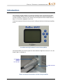
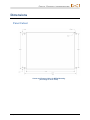
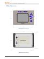
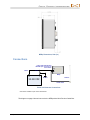
Multi-Function Display Installation Manual Panel Mounted MFDp DIGITAL CONTROL INCORPORATED [email protected] www.DigiTrak.com DIGITAL CONTROL INCORPORATED 403-2600-00-A, Aug 2013 © 2013 by Digital Control Incorporated. All rights reserved. Trademarks ® ® ® ® ® ® ® ® ® The DCI logo, CableLink , DataLog , DigiTrak , Eclipse , F2 , F5 , iGPS , MFD , SST , ® ® ® target-in-the-box , Target Steering , and TensiTrak are U.S. registered trademarks and DucTrak™, FBC™, FBP™, F Series™, FSD™, FasTrak™, LWD™, SBP™, SE™, SED™, SuperCell™, and TeleLock™ are trademarks of Digital Control Incorporated. Limited Warranty All products manufactured and sold by Digital Control Incorporated (DCI) are subject to the terms of a Limited Warranty. A copy of the Limited Warranty is included at the end of this manual; it can also be obtained by contacting DCI Customer Service, 425-251-0559 or 800-288-3610, or at DCI's website, www.digitrak.com. Important Notice All statements, technical information, and recommendations related to the products of DCI are based on information believed to be reliable, but the accuracy or completeness thereof is not warranted. Before using any DCI product, the user should determine the suitability of the product for its intended use. All statements herein refer to DCI products as delivered by DCI and do not apply to any user customizations not authorized by DCI nor to any third-party products. Nothing herein shall constitute any warranty by DCI nor will anything herein be deemed to modify the terms of DCI’s existing Limited Warranty applicable to all DCI products. The most recent version of this manual is available on DCI's website. Compliance Statement This equipment complies with Part 15 of the Rules of the FCC and with Industry Canada license-exempt RSS standards and with Australia Class License 2000 for LIPD (low interference potential devices). Operation is subject to the following two conditions: (1) this equipment may not cause harmful interference, and (2) this equipment must accept any interference received, including interference that may cause undesired operation. DCI is responsible for FCC compliance in the United States: Digital Control Incorporated, 19625 62nd Ave S, Suite B103, Kent WA 98032; phone 425-251-0559 or 800-288-3610. Changes or modifications to any DCI equipment not expressly approved and carried out by DCI will void the user’s Limited Warranty and the FCC’s authorization to operate the equipment. CE Requirements DigiTrak receivers are classified as Class 2 radio equipment per the R&TTE Directive and may not be legal to operate or require a user license to operate in some countries. The list of restrictions and the required declarations of conformity are available on DCI’s website, www.digitrak.com, under the Service & Support tab. Click on DOWNLOADS and select from the CE Documents pull-down menu to download, view, or print the documents. ii MFDp Installation Manual DIGITAL CONTROL INCORPORATED Contact Us United States DCI Headquarters 19625 62nd Ave S, Suite B103 Kent, Washington 98032, USA +1.425.251.0559 / 1.800.288.3610 +1.425.251.0702 fax [email protected] Australia 2/9 Frinton Street Southport QLD 4215 +61.7.5531.4283 +61.7.5531.2617 fax [email protected] China 368 Xingle Road Huacao Town Minhang District Shanghai 201107, P.R.C. +86.21.6432.5186 +86.21.6432.5187 fax [email protected] Europe Brueckenstraße 2 97828 Marktheidenfeld Germany +49.9391.810.6100 +49.9391.810.6109 fax [email protected] India DTJ 1023, 10th Floor DLF Tower A, DA District Center Jasola, New Delhi 110044 +91.11.4507.0444 +91.11.4507.0440 fax [email protected] Russia Molodogvardeyskaya Street, 4 Building 1, Office 5 Moscow, Russia 121467 +7.499.281.8177 +7.499.281.8166 fax [email protected] MFDp Installation Manual iii DIGITAL CONTROL INCORPORATED Table of Contents Introduction 1 Important Installation Guidelines 2 Dimensions 3 Panel Cutout.................................................................................................... 3 MFDp Dimensions ........................................................................................... 4 Connections .................................................................................................... 5 Power Connections 6 Input Requirements ......................................................................................... 6 Power Cable Specifications ............................................................................. 6 Antenna Connections 7 Antenna Ground Plane Mounting Requirements ............................................. 7 Coaxial Cable Requirements ........................................................................... 7 RG58A/U Coaxial Cable Assembly ................................................................. 8 DigiTrak Multi-Function Cable Box (MFCB) iv 9 MFDp Installation Manual DIGITAL CONTROL INCORPORATED Introduction This document provides guidance to technicians installing a panel-mounted DigiTrak MultiFunction Display (MFDp). Please read this entire document before beginning installation. If you have questions, contact our 24/7 customer service department at the numbers listed on page ii or via email at [email protected]. Consult the Operator’s Manual for this product for safety precautions and warnings regarding its use. Panel-Mounted DigiTrak Multi-Function Display (MFDp) The DigiTrak MFDp can receive signals from these families of DigiTrak receivers: F5, F2, SE, Eclipse, Mark V, and Mark III. 4-pin Deutsch DT06-4S connector on 2-wire cable Coaxial connector Power and Antenna Connections on Back of DigiTrak MFDp MFDp Installation Manual 1 DIGITAL CONTROL INCORPORATED Important Installation Guidelines For best telemetry performance of the DigiTrak system, observe the following important installation guidelines: 1. Install the shortest coaxial cable length possible between the MFDp and antenna mount. Longer cable results in greater signal loss. 2. Include a small service loop if there is any possibility of strain or tension at any point along the coaxial cable. Any loops of extra coaxial cable must be compressed so they do not act as an antenna for interference. Compressed Coaxial Cable Loops Do not bundle the cable with any other cabling. Ensure the cable does not kink after the MFDp is installed in the panel. 3. Every coaxial connection increases signal loss to some degree. Do not create any intermediate connections, such as an adapter or bulkhead pass-through, unless absolutely necessary. 4. The antenna must be mounted vertically (up or down) on a horizontal ground plane that is isolated from the drill rig’s metal framework (see Antenna Ground Plane Mounting Requirements on page 7). 5. Install the antenna base such that the whip is at least 24” away from adjacent vertical metal structures or other RF antennas. 6. Secure the coaxial cable with zip ties or other means to prevent unnecessary vibration, chaffing, or possible loosening of connections. 7. To prevent potential damage to the antenna or connector, avoid locations where the operator’s normal range of motion may bring him or her in contact with the antenna. 8. For drill rigs with no cab, mounting the antenna inside a nonmetallic cabinet provides excellent protection for the antenna and also eliminates unnecessary wind vibration during highway transit, but it is still imperative to maintain a clear line between the cabinet and the DigiTrak receiver. 9. It is acceptable to mount the 13” whip antenna upside down, but maintain the clearances mentioned in step 5 above. 10. Mount the antenna BNC fitting in a location that is fairly easily accessible, since users may need to remove the antenna at the end of every workday, especially when using the optional long whip antenna (PN 610-2520-00) for ranges beyond 1800 ft. 11. Test the mounting configuration to ensure the MFDp and DigiTrak receiver achieve a minimum line-of-sight range of 1800 ft. Note that an environmental interference such as power lines can compromise test results. Long whip antenna 2 13” whip antenna MFDp Installation Manual DIGITAL CONTROL INCORPORATED Dimensions Panel Cutout Cutout and Fastener Holes for MFDp Mounting (this image is not to scale) MFDp Installation Manual 3 DIGITAL CONTROL INCORPORATED MFDp Dimensions MFDp Dimensions, Front (in.) MFDp Dimensions, Rear (in.) 4 MFDp Installation Manual DIGITAL CONTROL INCORPORATED MFDp Dimensions, Side (in.) Connections Power cable with Deutsch DT06-4S 4-pin connector on 2-wire cable* White Black + - 12-28 VDC MFDp Ground Antenna Coaxial cable Power and Antenna Connections * This cable is available as part number 460-3825-00. The diagram on page 9 shows how to wire the MFDp with a Multi-Function Cable Box. MFDp Installation Manual 5 DIGITAL CONTROL INCORPORATED Power Connections A properly fitted 10 ft. 2-wire DC power cable (PN 460-3825-00) is available for the MFDp. If building a custom cable, take note of the following requirements. Input Requirements Use a male Deutsch DT06-4S 4-pin connector for the MFDp connection: Deutsch DT06-4S 4-pin Connector on 2-Wire Cable The power connector pin numbers molded into the cavity and printed on the back of the connector correspond to the following functions: Pin 1 – MFDp PWR (input power from 10-28 VDC, 3.2 W max; white wire) Pin 2 – MFDp GND (common ground for power and serial RS-232; black wire) Pin 3 – MFDp RS-232 RX Pin 4 – MFDp RS-232 TX Contacts 3 and 4 are used only in conjunction with the optional DigiTrak Multi-Function Cable Box (MFCB) (see page 9), which is supplied with the required 4-wire power and data cable. Power Cable Specifications Connect directly from the MFDp to the drill rig power supply, white (+), black (-). Minimum cable specifications are: 18 AWG tinned copper stranded wire Rated for outdoor service: resistant to oil, sunlight, and water Temperature rated at -40 to 105° C DCI recommends shielded twisted pair wire for best performance. Shielding must be connected to ground at both ends. 6 MFDp Installation Manual DIGITAL CONTROL INCORPORATED Antenna Connections Antenna Ground Plane Mounting Requirements Prior to installing the antenna ground plane, review the Important Installation Guidelines on page 2. A relatively small ground plane of 10” x 12” steel or aluminum will work well. The ground plane must be electrically isolated from the drill rig’s metal framework. For drill rigs with a cab, mount the ground plane on top and near the front edge of the cab roof to ensure the best telemetry performance. Install the 50 Ohm female bulkhead BNC connector in the center of the ground plane in a manufacturer-recommended mounting hole. 13” whip antenna Female bulkhead BNC connector Ground plane 50 Ohm Female Bulkhead BNC Connector Mounted in Ground Plane The ground plane must be horizontal and the antenna must be vertical to receive the best signal from the DigiTrak receiver. Install the ground plane where the antenna will be prominent, not surrounded by other metal, and has a clear line of site to the receiver. If using a long whip antenna, place the magnetic base as near to the center of the ground plane as possible. Coaxial Cable Requirements Prior to installing the coaxial cable, review the Important Installation Guidelines on page 2. A properly fitted 3 ft. cable (PN 460-0020-00) is available for the MFDp. If building a longer cable, take note of the following requirements. Caution Every coaxial connection increases signal loss to some degree. Do not create any intermediate connections, such as an adapter or bulkhead pass-through, unless absolutely necessary. MFDp Installation Manual 7 DIGITAL CONTROL INCORPORATED Install a single continuous length of RG58A/U 50 Ohm coaxial cable directly between the MFDp coaxial connector and antenna base. Physical Characteristic Specification Type RG-58A/U Impedance Z0 50 Ω Dielectric Solid polyethylene Time Delay 1.54 ns/ft Propagation velocity 65.9% of c Capacitance 29.6 pF/foot Outside dimensions 0.195 in. dB/100ft @ 400 MHz 13.2 Maximum voltage 1900 Vrms Shield Braid The recommended maximum cable length is 12 feet. However, since a shorter cable length results in less signal loss, use only enough to comfortably route from the MFDp to the antenna base. Test the finished installation assembly to ensure the MFDp and DigiTrak receiver achieve a minimum line-of-sight range of 1800 ft. Note that an environmental interference such as power lines can compromise test results. Note The coaxial cable shield must touch only the MFDp and the ground plane. RG58A/U Coaxial Cable Assembly Antenna Bulkhead Port Termination MFDp Port Termination Amphenol Connex 112202, 50 Ohm Female BNC Bulkhead (or equivalent) Amphenol Connex 122108, 50 Ohm male TNC (or equivalent) The bulkhead BNC termination accepts both the 13 in. wire whip antenna and optional long whip antenna BNC plug connectors. 8 MFDp Installation Manual DIGITAL CONTROL INCORPORATED DigiTrak Multi-Function Cable Box (MFCB) Using the MFDp with an optional cable transmitter is not possible with the 2-wire power cable shown in Power Connections on page 6. The DigiTrak Multi-Function Cable Box (MFCB) includes a 4-wire power and data cable (PN 460-0002-00) with Souriau and Deutsch fittings for connecting the DigiTrak MFDp directly to the MFCB, which provides both the data signal and power to the MFDp. For more information, download the MFCB manual from the DigiTrak website. MFDp Multi-Function Cable Box (MFCB) and 4-Wire Cable Power cable with Deutsch DT06-4S 4-pin connector on 2-wire cable* White Power and data cable with Deutsch DT064S 4-pin connector on 4-wire cable** Coaxial cable Black + - 12-28 VDC MFDp Ground Ground through pipe Serial port for SST laptop MFCB Antenna Housing to transmitter base is negative contact for grounding Cable Cable transmitter Compression fitting End plug Drill rod Housing MFDp Connections When Using the MFCB * This cable is available as part number 460-3825-00. ** This cable, part number 460-0002-00, is supplied with the MFCB. MFDp Installation Manual 9