1
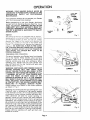
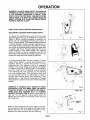
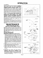
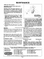
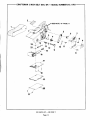
Sears
OWNERS
MANUAL
MODEL NO.
315.11701
CAUTION
Read Rules for
Safe Operation
and Instructions
Carefully
CRAFTSMAN
3 INCH
BELT SAN DER
DOUBLE
INSULATED
SAVE THIS MANUAL
FOR FUTURE REFERENCE
Introduction
Operation
Maintenance
Repair Parts
(UL)
%
Designed
2612547
10-81
182
exclusively
for and sold only by SEARS. ROEBUCK AND CO., Chicago,
,"
IL 60684 U.S.A.
PRINTED
IN
U.S,A
FULL ONE YEAR WARRANTY
ON CR_AFTSMAN B_.LT SANDER
If this Craftsman Belt Sander fails to give complete satisfaction within one year from the date of purchase RETURN IT TO THE NEAREST SEARS STORE THROUGHOUT THE UNITED STATES and Sears
will repair it, free of charge.
If this belt sander is used for commercial or rental purposes this warranty applies for only 90 days from
the date of purchase.
This warranty gives you specific legal rights, and you may also have other rights which vary from state
to state.
SEARS, ROEBUCK AND CO.
BSC 41 - 3
SEARS TOWER
CHICAGO, IL 60684
INTRODUCTION
GENERAL
Your Craftsman 3-Inch Belt Sander is suitable for
coarse, medium and fine sanding of wood, metals,
plastics and other materials. It is ideal when used for
smoothing
rough boards, chamfering,
rounding
edges and many other general sanding applications.
Its balanced design makes it easy to use. All the
bearings in this tool are lubricated with a sufficient
amount of high grade lubricant for the life of the unit
under normal operating conditions, therefore, no further lubrication is required.
DOUBLE INSULATION
Double insulation is a concept in safety, in electric
power tools, which eliminates the need for the usual
three wire grounded power cord and grounded supply system. Wherever there is electric current in the
tool there are two complete sets of insulation to protect the user. All exposed metal parts are isolated
from the internal metal motor components with protecting insulation.
RULES FOR SAFE OPERATION
READ ALL INSTRUCTIONS
--
IMPORTANT -- Servicing of a tool with double insulation requires extreme care and knowledge of the
system and should be performed only by a qualified
service technician.
For service, return the tool to
your nearest Sears store for repair which will be
done with original factory replacement parts. WARNING: KEEP HANDS AND FINGERS AWAY FROM
MOVING SANDING
BELT. ANY PART OF BODY
COMING IN CONTACT WITH MOVING BELT COULD
RESULT IN SERIOUS INJURY. KEEP HEAD AWAY
FROM SANDER AND SANDING AREA. HAIR COULD
GET CAUGHT IN MOVING PARTS AND FOREIGN
OBJECTS COULD GET THROWN
AWAY FROM
SANDER CAUSING INJURY.
WARNING: DO NOT ATTEMPT TO OPERATE UNTIL
YOU HAVE READ THOROUGHLY
AND UNDERSTAND COMPLETELY ALL INSTRUCTIONS,
RULES,
ETC. CONTAINED
IN THIS MANUAL. FAILURE TO
COMPLY CAN RESULT IN ACCIDENTS INVOLVING
FIRE, ELECTRIC SHOCK, OR SERIOUS PERSONAL
INJURY.
MAINTAIN
OWNER'S
MANUAL
AND
REVIEW FREQUENTLY
FOR CONTINUING
SAFE
OPERATION,
AND
INSTRUCTING
POSSIBLE
THIRD-PARTY USER.
1. KNOW YOUR POWER TOOL -- Read owner's
manual
carefully.
Learn its applications
and limitations
as well as the specific
potential
hazards peculiar to
this tool.
2. GUARD AGAINST
ELECTRICAL
SHOCK BY PREVENTING
BODY CONTACT
WITH GROUNDED
SURFACES.
For example:
Pipes, radiators,
ranges, refrigerator enclosures.
3. KEEP GUARDS IN PLACE and in working order.
4. KEEP WORK AREA CLEAN. Cluttered
areas and benches
invite
accidents.
5. AVOID DANGEROUS
ENVIRONMENT.
Don't use power tool in damp or wet
locations
or expose to rain. Keep work area well lit.
6. KEEP CHILDREN
AWAY. All visitors
should be kept safe distance
from work
area. Do not let visitors
contact
tool or extension
cord.
7. STORE IDLE TOOLS. When not in use, tools should be stored in dry, high or
locked-up
place -- out of reach of children.
8. DON'T FORCE TOOL. It will do the job better and safer at the rate for which it
was designed.
9. USE RIGHT TOOL. Don't force small tool or attachment
to do the job of a heavy
duty tool. Don't use tool for purpose
not intended
- for example
- Don't use
a circular
saw for cutting
tree limbs or logs.
10. WEAR PROPER APPAREL. No loose clothing
or jewelry to get caught
parts. Rubber gloves and footwear
are recommended
when work=ng
Also, wear protective
hair covering
to contain
long hair.
Page 2
in moving
outdoors.
RULES FOR SAFE OPERATION
(Continued)
if cutting
11. USE SAFETY
GLASSES
with all tools. Also face or dust mask
operation
is dusty.
12. DON'T ABUSE CORD. Never carry tool by cord or yank it to disconnect
from
receptacle.
Keep cord from heat, oil and sharp edges.
13. SECURE WORK. Use clamps or a vise to hold work. It's safer than using your
hand and it frees both hands to operate tool.
14. DON't OVERREACH.
Keep proper footing
and balance at all times.
15. MAINTAIN
TOOLS WITH CARE. Keep tools sharp at all times, and clean for best
and safest performance.
Follow
instructions
for lubricating
and changing
accessories.
16. DISCONNECT
TOOLS. When not in use, before servicing,
or when changing
attachments,
blades, bits, cutters,
etc., all tools should be disconnected.
17. REMOVE ADJUSTING
KEYS AND WRENCHES.
Always check to see that keys
and adjusting
wrenches
are removed
from tool before turning
it on.
18. AVOID ACCIDENTAL
STARTING.
Don't carry, plugged-in
tools with finger on
switch.
Be sure switch
is off when plugging
_n.
19. OUTDOOR
USE EXTENSION
CORDS. When tool is used outdoors,
use only
extension
cords suitable
for use outdoors.
Outdoor approved
cords are marked
with the suffix W-A. For example
- SJTW-A or SJOW-A.
20. NEVER USE THIS OR ANY POWER SANDER FOR WET SANDING.
Failure to
comply
can result
in electrical
shock
causing
serious
injury
or worse.
22. NEVER USE IN AN EXPLOSIVE
ATMOSPHERE.
Normal sparking
of the motor
could ignite fumes.
23. INSPECT TOOL CORDS PERIODICALLY
and if damaged,
have repaired at your
nearest Sears Repair Center.
24. INSPECT EXTENSION
CORDS PERIODICALLY
and replace if damaged.
25. KEEP HANDLES
DRY, CLEAN, AND FREE FROM OIL AND GREASE.
26. STAY ALERT. Watch what you are doing and use common sense. Do not operate tool when you are tired.
27. CHECK
DAMAGED
PARTS.
Before
further
use of the tool, a guard
or
other part that is damaged should be carefully checked to determine that it will
operate properly and perform its intended function. Check for alignment of moving parts, binding of moving parts, breakage of parts, mounting, and any other
conditions
that may affect its operation. A guard or other part that is damaged
should be properly repaired or replaced by an authorized service center unless
indicated elsewhere
in this instruction
manual.
28. DO NOT USE TOOL IF SWITCH DOES NOT TURN IT ON AND OFF. Have defect29.
30.
31.
Inspect for and remove all nails from lumber before sanding.
DRUGS, ALCOHOL,
MEDICATION.
Do not operate
tool under
drugs, alcohol,
or any medication.
SAVE THESE INSTRUCTIONS.
the influence
of
CAUTION
The operation of any sander can result In forelgn objects belng thrown into the eyes, whlch can result In
severe eye damage. Always wear safety glasses or
eye shlelds before commenclng power tool opera.
tlon. We recommend Wlde Vlslon Safety Mask for
use over spectacles, or standard safety glasses...
available at Sears Catalog Order or Retail Stores.
Page 3
OPERATION
WARNING: YOUR SANDER SHOULD NEVER BE
CONNECTED TO POWER SUPPLY WHEN YOU ARE
ASSEMBLING
PARTS
OR
PERFORMING
MAINTENANCE.
If any parts are missing do not operate
until the missing parts are replaced.
DATA
PLATE
your Sander
FRONT
HANDLE
Before attempting
to use your Sander, familiarize
yourself with all operating features (See Fig. 1) and
safety requirements.
WARNING: DO NOT ALLOW
FAMILIARITY WITH YOUR SANDER TO MAKE YOU
CARELESS. REMEMBER THAT A CARELESS FRACTION OF A SECOND IS SUFFICIENT TO INFLICT
SEVERE INJURY.
z ¸¸¸
SANDING
BELT
-TRACKING
SCREW
SWITCH
The switch of this tool is equipped with a "lock-on"
feature which is convenient when operating the tool
for extended periods of time. To lock on. simply
depress the trigger of the switch and depress the
lock button located on the side of the handle. See
Figure 1. To release the lock, depress the trigger and
release it. BE SURE TOOL IS NOT IN THE "LOCKON" POSITION BEFORE CONNECTING TO POWER
SUPPLY SOURCE. DO NOT LOCK THE TRIGGER ON
JOBS WHERE THE SANDER MAY NEED TO BE
STOPPED SUDDENLY.
PREPARING FOR OPERATION
Fig. 1
For ease of operation your Sander has a front handle
and a rear handle. These handles allow two-hand
operation
which aids in maintaining
control
and
keeping sanding area level with workpiece.
When
operating
your Sander hold the front handle with
your left hand and the rear handle with your right
hand as shown in Fig. 2.
WARNING: KEEP HANDS AND FINGERS CLEAR OF
MOVING
SANDING
BELT AND FRONT
IDLER
PULLEY. FAILURE TO DO SO WILL RESULT IN THE
SANDING OF YOUR HANDS OR FINGERS. See Fig.
3. WARNING: DO NOT LET YOUR FINGERS REST
OVER THE FRONT OR RIGHT EDGE OF THE
SANDER AS SHOWN IN FIG. 3. IF THE SANDING
BELT WERE TO RUN OFF, OR IF IT WERE NOT PROPERLY ADJUSTED, YOUR FINGERS COULD COME
IN CONTACT WITH THE MOVING SANDING BELT
RESULTING
IN POSSIBLE
SERIOUS
INJURY.
Always operate your Sander in the correct position
as shown in Fig. 2.
CORRECT
Fig. 2
Selecting the correct size and type sanding belt is an
important step in achieving a high quality sanded
finish. Standard 3 inch x 21 inch sanding belts made
of aluminum oxide, silicone carbide, and other synthetic abrasives
are best for power sanding.
In
general, coarse grit will remove the most material
and finer grit will produce best finish in all sanding
operations. The condition of the surface to be sanded will determine which grit belt will do the job. If the
surface is rough, start with a coarse grit belt sanding
until surface is uniform. Medium grit belt may then
be used to remove scratches left by the coarser belt
and finer grit belt used for finishing of the surface.
Always continue
sanding with each grit belt until
surface is uniform.
INCORRECT
Fig. 3
Page 4
OPERATION
WARNING: ALWAYS WEAR SAFETY GLASSES OR
EYESHIELDS WHEN OPERATING YOUR SANDER.
IF THE SANDING OPERATION IS DUSTY, ALSO
WEAR A FACE OR DUST MASK. FAILURE TO DO SO
COULD RESULT IN DUST OR LOOSE PARTICLES
BEING THROWN INTO YOUR EYES, RESULTING IN
POSSIBLE SERIOUS INJURY.
INSTALLING
DISCONNECT
AND ADJUSTING
SANDER
SANDING
BELT
FROM POWER SUPPLY.
To release the sanding belt, push the front pulley
squarely against the top of workbench as shown in
figure 4. When sufficient
pressure is exerted, the
spring will be compressed
allowing the pulley to
lock in a rear position. This frees the sanding belt so
it can be removed. Install new belt making sure arrow inside of belt is pointing in the direction of rotation, which is clockwise when looking into open side
of sander. See Fig. 5. Roughly align the belt to its
correct position. Then place sander into position
shown in figure 6. Insert a screwdriver
into slot on
idler pulley yoke and apply backward pressure. The
pulley will snap back into operating position.
Fig. 4
Fig. 5
To adjust sanding belt, connect Sander to power
supply. Place Sander in upside down position as illustrated. See Fig. 7. NOTE: This position is for adjustments
only. The Sander is not in an operating
position. Pull switch trigger and release immediately. Observe tracking of sanding belt. If the sanding
belt runs inward, turn the tracking screw clockwise.
If the sanding belt runs outward, turn the tracking
screw counterclockwise.
This should be done until
you are sure belt will not run off sander, or come in
contact with internal parts. After installing
a new
sanding belt, it may become necessary to change
the adjustment
several times until the belt becomes
pliable.
WARNING: IF SANDING BELT BEGINS TO WEAR
EXCESSIVELY ON THE INNER EDGE, RE-ADJUST
TRACKING SCREW. IT IS ADJUSTED TOO FAR IN.
WARD AND THE SANDING
BELT IS RUBBING
AGAINST INTERNAL PARTS. When you are sure the
belt will not rub against internal parts, start the
Sander and fine adjust the tracking screw until the
belt stabilizes.
Fig. 6
SANDING
BELT
t
"_
When correctly adjusted, the outer edge of the belt
will be even with the outer edge of the base of the
Sander. Belt life will be greatly increased if a few
seconds are spent adjusting the belt tracking.
TRACKING
SCREW
o
Fig. 7
Page 5
OPERATION
TO OPERATE
Clamp or otherwise secure the work to prevent it
from
moving
under the Sander.
WARNING:
UNSECURED WORK COULD BE THROWN BACK
TOWARD OPERATOR CAUSING INJURY. Before
placing Sander on work surface, press the trigger
switch and let the motor reach its maximum speed,
then lower the Sander to the work surface with a
slight forward motion. Using the rear handle to control the Sander and the front handle only to guide it,
move it slowly over the work. See Fig. 8. Allowing the
Sander to remain in one place will result in an
uneven surface. WARNING: KEEP A FIRM GRIP ON
SANDER WITH BOTH HANDS AT ALL TIMES.
FAILURE TO DO SO COULD RESULT IN LOSS OF
CONTROL LEADING TO POSSIBLE SERIOUS INJURY. The Sander was designed to provide the proper weight on the sanding belt and extra pressure
will only result in uneven work, clogged belts, and
possible motor burnout.
Use a coarse belt when heavy cutting is desired, not
heavy pressure. The importance of this cannot be
over-emphasized, the weight has been built into the
tool to give the most efficient pressure at the proper
location.
,I
Fig. 8
WEAR
PAN HEAD
PLATE
_
SCREW
"_'_
:
_--_,,
MAINTENANCE
WHEN SERVICING
USE ONLY
IDENTICAL
REPLACEMENT
PARTS.
Periodically sawdust will accumulate between the
base and idler roller assembly, causing difficulty
when releasing tension on the sanding belt. It may
also cause the sanding belt to slip during use and
can make sanding belt tracking adjustments (see
page 5) difficult.
TO CLEAN SAWDUST FROM
IDLER ROLLER ASSEMBLY
DISCONNECT SANDER FROM POWER SUPPLY.
1. Remove sanding belt from sander. See Installing
and Adjusting Sanding Belt, Page 5. Once sanding belt is removed, insert screwdriver
into slot
and snap IDLER ROLLER ASSEMBLY back into
operating position. Lock and release the idler
roller assembly several times, without a sanding
belt installed. The mechanism should now operate freely. Re-install sanding belt, make proper
adjustments, and test the operation of the tool to
determine whether it is performing satisfactorily.
If the performance has not improved, proceed to
Step 2.
2. Remove the two pan head screws. Then remove
wear plate and backing pad. See Figure 9.
3. Remove tracking screw, washer, spring, and flat
head screws. Then remove base.
4. Using a clean soft cloth or brush, clean base,
idler roller assembly, tracking screw, and motor
housing.
5. Reassemble
tool. NOTE: THE LEAF SPRING,
BUSHING,
IDLER ROLLER ASSEMBLY,
AND
IDLER ROLLER SPRING MUST BE POSITIONED
AS SHOWN IN FIGURE 10. Also, make sure slot
in idler roller assembly
is engaged with motor
housing pin and bushing.
TRACKING
SCREW
_'_
TRACK
_ _
NG
SCREW
SPRING
_
,MOTOR
.
HOUSING
+
WASHER
MOTOR
HOUSING
PIN
Fig. 9
LEAF
BUSHING_
SPRING
MOTOR
_PIN
HOUSING
IDLER ROLLER
SPRING
IDLER ROLLER
ASSEMBLY Fig. 10
Page 6
MAINTENANCE
TIMING BELT REPLACEMENT
DISCONNECT SANDER FROM POWER SUPPLY
BEFORE SERVICING
WARNING: WHEN REPLACING TIMING BELT, USE
REPLACEMENT
BELT NUMBER 990077.001 ONLY.
See Key Number 5 on Parts List, Page 11. FAILURE
TO DO SO WILL INTERFERE WITH THE INSULA.
TION SYSTEM AND THE PERFORMANCE
OF THE
TOOL, CAUSING THE BELT TO SLIP AND WEAR EXCESSIVELY.
1. Remove sanding belt from sander. See installing and adjusting sanding belt, Page 5.
NOTE:
REMOVING
THE
SANDING
BELT
WILL
SIMPLIFY THE PROCESS OF INSTALLING YOUR
NEW TIMING BELT.
2. Remove the two belt cover screws. Then remove
the belt cover. See Key Numbers 7 and 8 on exploded view and/or parts list, pages 10 and 11.
3. Force old belt from small pulley with a screwdriver and remove it from large pulley. If it is completely worn out, simply cut the old belt in two
and remove it.
4. Install new belt over large pulley first, making
sure teeth on belt mesh with teeth on pulley. See
Figure 11.
GENERAL
Only the parts shown on parts list, page eleven, are
intended to be repaired or replaced by the customer.
All other parts represent an important
part of the
double insulation system and should be serviced only by a qualified service technician.
Avoid using solvents when cleaning plastic parts.
Most plastics are susceptible to various types of
commercial solvents and may be damaged by their
use. Use clean cloths to remove dirt, carbon dust,
etc.
EXTENSION
CORDS
The use of any extension cord will cause some loss
of power. To keep the loss to a minimum and to prevent tool overheating, follow the recommended cord
sizes on the chart at right. When tool is used outdoors, use only extension cords suitable for outdoor
use and so marked. Extension cords are available at
Sears Catalog Order or Retail Stores.
\
-APPLY PRESSURE
HERE,WHILE TURNING
COUNTERCLOCKWISE
Fig.
5. Holding the belt as shown in Figure 11, press
the belt onto the small pulley. NOTE: TO SIMPLIFY THE PROCESS, TURN THE LARGE PULLEY
IN A COUNTERCLOCKWISE
DIRECTION AS YOU
PRESS THE BELT ONTO THE SMALL PULLEY.
6. Re-assemble
beq cover and screws. WARNING:
THE BELT COVER IS PART OF THE DOUBLE INSULATION SYSTEM AND MUST BE REPLACED
PRIOR TO USE. FAILURE TO DO SO COULD
RESULT IN ELECTRICAL SHOCK CAUSING POSSIBLE SERIOUS INJURY.
When electric tools are used on fiberglass
boats,
sports cars, etc., it has been found that they are subject to accelerated
wear and possible
premature
failure, as the fiberglass
chips and grindings
are
highly abrasive to bearings, brushes, commutator,
etc. Consequently
it is not recommended
that this
tool be used for extended work on any fiberglass
material. During any use on fiberglass it is extremely
important that the tool is cleaned frequently by blowing with
an air jet. ALWAYS
WEAR SAFETY
GLASSES OR EYE SHIELDS BEFORE BEGINNING
THIS OPERATION.
Wire Size A.W.G.
Extension Cord Length
25-50 Ft.
16
_
50-100 Ft.
14
WARNING: CHECK EXTENSION CORDS BEFORE
EACH USE. IF DAMAGED, REPLACE IMMEDIATELY.
NEVER USE TOOL WITH DAMAGED CORD SINCE
TOUCHING THE DAMAGED AREA COULD CAUSE
ELECTRICAL SHOCK RESULTING IN SERIOUS INJURY.
THE FOLLOWING RECOMMENDED
ACCESSORIES ARE CURRENT AND
CORD LOCK
WERE AVAILABLE AT THE TIME THIS MANUAL WAS PRINTED.
Cat. No. _12595
CLOTH BACKED SANDING BELTS
POLYESTER BACKEp SANDING
CARRYING CASE
Cat. No. _) 22304-X.Fine
at. No. _ 23201-X.F,ne
Cat. No. _ 1473
Cat. No. _ 23202-Fine
Cat. No. _)22301-Fine
Cat. No. _ 23203-Medium
Cat. No. _122302-Medium
Cat. No. _)22303-Coarse
Cat. No. _ 23204-Coarse
I:R
Cat. No. _) 22305-X-Coarse
CAUTION:
The use of attachments
11
or accessories
Page 7
not listed above might be hazardous.
BELTS
NOTES
Page 8
NOTES
Page 9
CRAFTSMAN
3 INCH
BELT SAN,IER
-- MODEL
NUMBER
NOTE "A"
315.11701
PAGE 11
5
6
7
3
13
12
11
/
8
t
18
21
FOR PARTS LIST --
SEE PAGE 11
Page 10
CRI:iFTSIqI:IN"
Sears
3 INCH
BELT SANDER
OWNERS
MANUAL
DOUBLE
SERVICE
INSULATED
Now that you have purchased
your. Belt Sander,
should a need ever exist for repair parts or service,
simply contact
any Sears Service Center and most
Sears, Roebuck
and Co. stores. Be sure to provide
all pertinent
facts when you call or visit.
MODEL NO.
The model number of your Belt Sander will be found
on the plate located on top of your sander.
315.11701
HOW TO ORDERREPAIR.PARTS
WHEN ORDERING
THE FOLLOWING
REPAIR PARTS,
INFORMATION:
ALWAYS
•
PART NUMBER
•
PART DESCRIPTION
•
MODEI_"4 U M BE R
•
NAME OF ITEM
3" Belt Sander
315 .,11_
_
_ll parts l_stea may be ordered from
vice Center and most Sears stores.
any Sears
GIVE
Ser-
If the parts you need are not stocked
locally,
your
order will be electronically
transmitted
to a Sears
Repair Parts Distribution
Center for handling.
SEARS, ROEBUCK
AND CO., Chicago,
IL 60684 U.S.A.