1
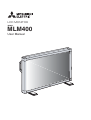
LCD MONITOR
MODEL
MLM400
User Manual
MLM400
Table of Contents
Important Information .......................................................................................................................... 1
Safety Precautions, Maintenance, & Recommended Use ................................................................. 2
Contents .................................................................................................................................................... 3
Attaching LCD Options ............................................................................................................................ 4
Parts Name and Functions
Control Panel ............................................................................................................................. 5
Terminal Panel .......................................................................................................................... 6
Wireless Remote Control ........................................................................................................ 7
Operating Range for the Remote Control .......................................................................... 8
Handling the Remote Control ................................................................................................ 8
Setup Procedure ...................................................................................................................................... 9
Connections
Wiring Diagram .................................................................................................................... 10
Connecting the LCD Monitor to a PC ............................................................................... 11
Connecting to a Macintosh Computer ............................................................................ 12
Connecting to a Computer with a Digital Output ........................................................ 13
Connecting to a VCR or Laser Disc Player ...................................................................... 14
Connecting to a DVD Player ............................................................................................... 15
Connecting to a Stereo Amplifier .................................................................................... 16
Basic Operation
Power On and Off modes ......................................................................................................... 17
Power Indicator ........................................................................................................................ 18
When Using Power Management Function .......................................................................... 18
Selecting a video source ........................................................................................................ 18
Picture Size ............................................................................................................................... 18
Picture Mode ............................................................................................................................. 18
On-screen Information ........................................................................................................... 18
On-Screen-Menu Controls
Computer ................................................................................................................................... 19
DVD & HD ..................................................................................................................................... 23
AV INPUT .................................................................................................................................... 25
Using the LCD with a Personal Computer (PC) ................................................................................... 28
Features ..................................................................................................................................................... 30
Troubleshooting ....................................................................................................................................... 31
References ................................................................................................................................................. 32
Specifications ........................................................................................................................................... 33
Limited Warranty ..................................................................................................................................... 34
Important Information
WARNING
TO PREVENT FIRE OR SHOCK HAZARDS, DO NOT EXPOSE THIS UNIT TO RAIN OR MOISTURE. ALSO, DO NOT USE THIS UNIT'S
POLARIZED PLUG WITH AN EXTENSION CORD RECEPTACLE OR OTHER OUTLETS UNLESS THE PRONGS CAN BE FULLY INSERTED.
REFRAIN FROM OPENING THE CABINET AS THERE ARE HIGH VOLTAGE COMPONENTS INSIDE. REFER SERVICING TO QUALIFIED
SERVICE PERSONNEL.
CAUTION
CAUTION:TO REDUCE THE RISK OF ELECTRIC SHOCK, MAKE SURE POWER CORD IS UNPLUGGED FROM WALL SOCKET. TO FULLY
DISENGAGE THE POWER TO THE UNIT, PLEASE DISCONNECT THE POWER CORD FROM THE AC OUTLET. DO NOT REMOVE
COVER (OR BACK). NO USER SERVICEABLE PARTS INSIDE. REFER SERVICING TO QUALIFIED SERVICE PERSONNEL.
This symbol warns user that uninsulated voltage within the unit may have sufficient magnitude to cause electric shock. Therefore, it is
dangerous to make any kind of contact with any part inside this unit.
This symbol alerts the user that important literature concerning the operation and maintenance of this unit has been included. Therefore,
it should be read carefully in order to avoid any problems.
Canadian Department of Communications Compliance Statement
DOC: This Class B digital apparatus meets all requirements of the Canadian Interference-Causing Equipment Regulations.
C-UL: Bears the C-UL Mark and is in compliance with Canadian Safety Regulations according to CAN/CSA C22.2 No.
60950.
FCC Information
1. Use the attached specified cables with the MLM400 (L40HV201) color monitor so as not to interfere with radio and television
reception.
(1) Please use the supplied power cord or equivalent to ensure FCC compliance.
(2) Please use the supplied shielded video signal cable, 15-pin mini D-SUB to 15-pin mini D-SUB.
2. This equipment has been tested and found to comply with the limits for a Class B digital device, pursuant to part 15 of the FCC
Rules. These limits are designed to provide reasonable protection against harmful interference in a residential installation. This
equipment generates, uses, and can radiate radio frequency energy, and, if not installed and used in accordance with the
instructions, may cause harmful interference to radio communications. However, there is no guarantee that interference will
not occur in a particular installation. If this equipment does cause harmful interference to radio or television reception, which
can be determined by turning the equipment off and on, the user is encouraged to try to correct the interference by one or more
of the following measures:
• Reorient or relocate the receiving antenna.
• Increase the separation between the equipment and receiver.
• Connect the equipment into an outlet on a circuit different from that to which the receiver is connected.
• Consult your dealer or an experienced radio/TV technician for help.
If necessary, the user should contact the dealer or an experienced radio/television technician for additional suggestions. The
user may find the following booklet, prepared by the Federal Communications Commission, helpful: ”How to Identify and Resolve
Radio-TV Interference Problems.“ This booklet is available from the U.S. Government Printing Office, Washington, D.C., 20402,
Stock No. 004-000-00345-4.
1
Safety Precautions, Maintenance & Recommended Use
Safety Precautions and Maintenance
CAUTION
FOR OPTIMUM PERFORMANCE, PLEASE NOTE THE FOLLOWING WHEN
SETTING UP AND USING THE MLM400 LCD COLOR MONITOR:
• DO NOT OPEN THE MONITOR. There are no user serviceable parts
inside and opening or removing covers may expose you to dangerous shock hazards or other risks. Refer all servicing to qualified service personnel.
• Do not spill any liquids into the cabinet or use your monitor near
water.
• Do not insert objects of any kind into the cabinet slots, as they may
touch dangerous voltage points, which can be harmful or fatal or
may cause electric shock, fire or equipment failure.
• Do not place any heavy objects on the power cord. Damage to the
cord may cause shock or fire.
• Do not place this product on a sloping or unstable cart, stand or
table, as the monitor may fall, causing serious damage to the monitor.
• When operating the MLM400 monitor with its AC 220-240V power
supply, use a power supply cord that matches the power supply voltage of the AC power outlet being used. The power supply cord you
use must have been approved by and comply with the safety standards of your country. (Type H05VV-F 3G 1mm2 should be used in
Europe)
• In UK, use a BS-approved power cord with molded plug having a
black (13A) fuse installed for use with this monitor. If a power cord is
not supplied with this monitor, please contact your supplier.
• Do not place any objects onto the monitor and do not use the monitor
outdoors.
• The inside of the fluorescent tube located within the LCD
monitor contains mercury.
• Do not bend power cord.
• Do not use monitor in high temperature, humid, dusty, or oily areas.
• If glass is broken, handle with care.
• Do not cover vent on monitor.
• If monitor or glass is broken, do not come in contact with the liquid
crystal and handle with care.
• Allow adequate ventilation around the monitor so that heat can properly dissipate. Do not block ventilated openings or place the monitor
near a radiator or other heat sources. Do not put anything on top of
monitor.
• The power cable connector is the primary means of detaching the
system from the power supply. The monitor should be installed close
to a power outlet which is easily accessible.
• Handle with care when transporting. Save packaging for
transporting.
• Please follow the bylaws or rules of your municipality to
dispose of the tube properly.
• Keep the holes on the back of the LCD clean of dirt and dust.
It is recommended to wipe holes with a soft cloth a minimum of
once per year.
Immediately unplug your monitor from the wall outlet and refer
servicing to qualified service personnel under the following
conditions:
• When the power supply cord or plug is damaged.
• If liquid has been spilled, or objects have fallen into the monitor.
• If the monitor has been exposed to rain or water.
• If the monitor has been dropped or the cabinet damaged.
• If the monitor does not operate normally by following operating
instructions.
Recommended Use
CAUTION
CORRECT PLACEMENT AND ADJUSTMENT OF THE MONITOR CAN
REDUCE EYE, SHOULDER AND NECK FATIGUE. CHECK THE FOLLOWING WHEN YOU POSITION THE MONITOR:
• For optimum performance, allow 20 minutes for warm-up.
• Rest your eyes periodically by focusing on an object at least 20
feet away. Blink often.
• Position the monitor at a 90˚ angle to windows and other light
sources to minimize glare and reflections.
• Clean the LCD monitor surface with a lint-free, nonabrasive cloth.
Avoid using any cleaning solution or glass cleaner.
• Adjust the monitor’s brightness and contrast controls to enhance
readability.
• Avoid displaying fixed patterns on the monitor for long periods of
time to avoid image persistence (afterimage effects).
• Get regular eye checkups.
• The lamp of backlight contains mercury. Please handle it appropriately in case of disposal.
Ergonomics
To realize the maximum ergonomics benefits, we recommend the following:
• Use the preset Size and Position controls with standard
signals
• Use the preset Color Setting
• Use non-interlaced signals with a vertical refresh rate between
58-62Hz
• Do not use primary color blue on a dark background, as it is
difficult to see and may produce eye fatigue to insufficient contrast
For more detailed information on setting up a healthy work
environment, write the American National Standard for Human Factors Engineering of Visual Display Terminal Workstations – ANSI-HFS
Standard No. 100-1988 – The Human Factors Society, Inc. P.O. Box
1369, Santa Monica, California 90406.
2
Contents
Your new MLM400 monitor box* should contain the following:
•
•
•
•
•
•
•
•
LCD monitor
Power Cord (3m)
Video Signal Cable – SC-B113 (4m)
User’s Manual
Wireless Remote Control and AA Batteries
Clamper x 2
Screw (M4 x 10) x 2
CD-ROM
•
•
•
•
Ferrite Core x 4
Self-standing feet x 2
Screw (M5 x 40) x 4
Band x 3
Screw (M5 x 40)
for stand x 4
Self-standing
feet x 2
MLM400
Power Cord
Video Signal Cable
(D-SUB to D-SUB Cable)
Screw (M4 x 10 ) x 2
LCD MONITOR
Clamper x 2
Ferrite Core x 4
MODEL
MLM400
User Manual
Band x 3
CD-ROM
User’s Manual
Wireless Remote Control
and AA Batteries
*Install an attached stand at the time of unpacking when it uses with the stand.
*Remember to save your original box and packing material to transport or ship the monitor.
The following components are available to use with the MLM400. To obtain the optional components and additional
information, contact Customer Service at (888) 307-0309.
• Macintosh Cable Adapter
• External Speakers
3
Attaching LCD Options
You can attach mounting accessories to the LCD monitor in one of the
following two ways:
Ventilation Requirements for enclosure
mounting
1. In the upright position
To allow heat to disperse, leave space between surrounding objects
as shown in the diagram to the right.
*
MLM400
2. Lay the screen face down
*Ambient temperature should be less than 40 deg C
Protective Sheet
To avoid falling down
Fasten the LCD monitor to a wall using a cord or chain which is sufficient to support the weight of the LCD monitor (approx. 31.5kg).
Table
Screw Holes
Tabletop Stand
To avoid damaging the screen face, place the protective sheet on the
table to lay the LCD on. The protective sheet was wrapped around the
LCD in the original packaging.
This device cannot be used or installed without the Tabletop Stand or
other mounting accessory. For proper installation it is strongly recommended to use a trained, Mitsubishi authorized service person. Failure to follow Mitsubishi standard mounting procedures could result in
damage to the equipment or injury to the user or installer. Product
warranty does not cover damage caused by improper installation.
Failure to follow these recommendations could result in voiding your
warranty.
Cord or Chain
Clamper
Screw
Before moving the LCD monitor, the cord or chain should be removed.
When using mounting accessories, other than Mitsubishi compliant
and approved, they must be VESA-compatible mounting method.
Mitsubishi strongly recommends using screws M6 size and 8mm in
length. If using screws longer than 8mm, check the depth of the
hole.
(Recommended Fastern Force: 274 ~ 362N•cm)
Mitsubishi recommends using mounting interface that comply with
UL1678 standard in North America.
4
Parts Name and Functions
Control Panel
MLM400
9
10
Button Location
EXIT
8
1 POWER button (
7
6
5
4
INPUT
MUTE
3
2
)
Switches the power on/off.
NOTE: The Main Power Switch must be in the ON position for this
button to work.
2 MUTE button
Switches the audio mute ON/OFF.
7 DOWN (
1
) button
Activates the on-scren menu when the on-screen menu is turned-off.
Acts as button to move the highlighted area down to select the adjustment with on-screen menu.
8 EXIT button
Activates the on-screen menu when the on-screen menu is turned-off.
Acts as EXIT button to move to previous menu with OSM menu.
3 INPUT button
Acts as SET button with on-screen menu.
Selects the signal connected with the RGB input connector. (Toggle
switches between [RGB1], [RGB2], [RGB3], [DVD/HD], or [VIDEO].)
4 PLUS (+) button
9 Remote control sensor and Power indicator
Receives the signal from the remote control (when using the wireless
remote control). See also page 8.
Glows green when the LCD monitor is in active and glows red when
the LCD is in POWER OFF mode. When the LCD is in power save
mode, it will glow both green and red.
Acts as (+) button to increase the adjustment with on-screen menu.
Increase the audio output level when the on-screen menu is turned off.
5 MINUS (-) button
Acts as (-) button to decrease the adjustment with on-screen menu.
Decrease the audio output level when the on-screen menu is turned
off.
6 UP (
10 Main Power Switch
Rocker Switch for the main power on/off.
NOTE: This switch must be in the ON position for the Power button to
work.
11 Control Key Lock Mode
) button
Activates the on-screen menu when the on-screen menu is turned-off.
Acts as
button to move the highlighted area up to select the adjustment with on-screen menu.
This control completely locks out access to all Control Key functions
after three (3) seconds.
To activate the control key lock function, press both of “ “ and
“ “ and hold down simultaneously.
To resume back to user mode, press both “ “ and “ “ and hold
simultaneously for three (3) seconds.
5
Parts Name and Functions –continued
Terminal Panel
1 AC IN connector
6 AUDIO IN 1,2,3
Connects with the supplied power cord.
To input audio signal from external equipment such as a computer, VCR
or DVD player.
2 RGB 1 IN (DVI-D)
7 AUDIO OUT
To input digital RGB signals from a computer having a digital RGB
output.
To output the audio signal from the AUDIO IN 3 jack.
* This connector does not support analog input.
8 VIDEO
3 RGB 2 IN (mini D-Sub 15 pin)
To input a analog RGB signals from a personal computer or other
VIDEO IN connector (BNC and RCA): To input a composite video
signal. BNC and RCA are not available at the same time.
RGB equipment.
(Use only one input).
VIDEO OUT connector (BNC): To output the composite video signal
from the VIDEO IN connector.
S-VIDEO IN connector (DIN 4 pin): To input the S-video (Y/C separate
4 RGB 3 DVD/HD [R/Cr/Pr, G/Y, B/Cb/Pb, H, V] (BNC)
IN connector: To input the analog RGB signals or signals from other
RGB equipment. Also for connecting equipment such as a DVD
player or HDTV laser disc player. A Sync-on-Green signal
signal).
9 EXTERNAL CONTROL (mini D-Sub 9 pin) RS232
can be connected to the G/Y connector.
IN connector: Use when operating the LCD monitor from the RGB
equipment like a computer.
5 RGB OUT connector (BNC)
To output the signal from the RGB 2 or RGB 3 DVD/HD IN connector.
10 EXTERNAL SPEAKER TERMINAL
To output the audio signal from AUDIO 1, 2 or 3 jack.
6
Parts Name and Functions –continued
Wireless Remote Control
5
4
7 VOLUME UP button
3
Increase the audio output level.
8 VOLUME DOWN button
Decrease the audio output level.
9 PIP (Picture In Picture) button
1
ON/OFF button: Toggle switches between PIP-ON/
POP-ON/OFF.
INPUT button: Select the ‘picture in picture’ input signal.
CHANGE button: Replaces to the main picture and sub
2
picture.
6
9
RGB1
RGB2
RGB3
DVD/HD
VI DE O
RGB1
_
_
_
✓
✓
RGB2
_
_
_
_
✓
RGB3
_
_
_
_
✓
DVD/HD
_
_
_
_
_
VIDEO
_
✓
✓
_
_
8
11
13
Main Picture
7
10
14
17
16
15
Sub Picture
Note: The aspect ration of PIP synchronizes with a setup in the Main Picture.
10 STILL button
12
ON/OFF button: To on/off the still picture mode.
19
CAPTURE button: Capture the new picture.
11 DISPLAY button
To turn the on-screen information on/off. See page 18.
18
12 AUTO SETUP button
To enter the auto setup menu. See page 21.
1 POWER button
13 MENU button
Switches the power on/off.
To on/off the menu mode.
* If Power Indicator is not glowing, then no controls will work.
14 UP button
2 INPUT button
Acts as
button to move the highlighted area up to select the
adjustment with on-screen menu.
Selects from input signal, [RGB1], [RGB2], [RGB3], [DVD/HD],
[VIDEO].
In PIP mode, the small screen moves up.
3 AUDIO INPUT button
15 DOWN button
Selects from input audio signal, [AUDIO1], [AUDIO2],
Acts as
button to move the highlighted area down to select the
adjustment with on-screen menu.
[AUDIO3]
In PIP mode, the small screen moves down.
4 SIZE button
16 MINUS button decrease
Selects picture size, [FULL], [NORMAL], [WIDE]. See page 18.
Acts as (-) button to decrease the adjustment with on-screen menu.
5 PICTURE MODE button
In PIP mode, the small screen moves left.
Selects from picture mode, [HIBRIGHT], [STANDARD], [sRGB],
[CINEMA].
HIBRIGHT: for moving image such as DVD
STANDARD: for images
sRGB: for text based images
17 PLUS button increase
Acts as (+) button to increase the adjustment with on-screen menu.
In PIP mode, the small screen moves right.
18 SET button
CINEMA: for movies. See page 18.
Acts as SET button with on-screen menu.
6 MUTE button
19 EXIT button
To on/off the mute function.
Turn to previous on-screen menu.
7
Parts Name and Functions –continued
Operating Range for the Remote Control
Caution
Point the top of the remote control toward the LCD monitor's remote
sensor during button operation.
Use the remote control within a distance of about 7 m/23 ft. from the
front of the LCD monitor's remote control sensor and at a hori- zontal
and vertical angle of within 30° within a distance of about 3 m/10 ft.
The remote control system may not function when direct sunlight or
strong illumination strikes the remote control sensor of the LCD monitor, or when there is an object in the path.
Handling the remote control
MLM400
*
*
*
30o
30o
8
Other than to install the batteries, do not open the remote.
Do not allow water or other liquid to splash onto the remote control. If the remote control gets wet, wipe it dry immediately.
Avoid exposure to heat and steam.
Setup Procedure
1. Determine the installation location
6. Operate the attached external equipment
CAUTION
Display the signal on the external equipment you wish.
Installing your LCD display must be done by a qualified technician.
7. Adjust the sound
Contact your dealer for more information.
Make adjustments when adjustment of the volume is required.
8. Adjust the screen (See pages 19-27)
CAUTION
MOVING OR INSTALLING THE LCD MONITOR MUST BE DONE BY
TWO OR MORE PEOPLE. Failure to follow this caution may result in
injury if the LCD monitor falls.
Make adjustments when adjustment of the screen display
position.
9. Adjust the image (See page 19-27)
Make adjustments when picture adjustment such as the brightness or
IMPORTANT
Lay the protective sheet, which was wrapped around the LCD monitor
when it was packaged, beneath the LCD monitor so as not to scratch
the panel.
contrast is required.
10. When monitor is installed in the portrait
position
2. Install the remote control batteries
The remote control is powered by 1.5V AA batteries. To install or
replace batteries:
1. Press and slide to open the cover.
2. Align the batteries according to the (+) and (–) indications inside
the case.
2 Insert the batteries
Remove the stand (feet).
•
Left edge should be upper from front view.
11. When installing the monitor to a wall
How to remove the stand
1. Spread the protective sheet on the flat surface, such as
a desk.
2. Place monitor on the protective sheet.
3. Remove 2 screws by screwdriver and place them in a safe
place for reuse.
How to install stand
1. Please turn monitor off.
2. Insert claws of monitor to stand holes until clicks.
3. Fasten 2 screws(M5 x 40mm) on both sides of the monitor.
Torque 280 ~ 300N•cm.
3. Replace the cover.
1 Remove the cover
•
3 Replace the cover
CAUTION
Incorrect usage of batteries can result in leaks or bursting. Mitsubishi
recommends the following battery use:
• Place "AA" size batteries matching the + and - signs on each
battery to the + and - signs of the battery compartment.
• Do not mix battery brands.
• Do not combine new and old batteries. This can cause a shorten
life or liquid leakage of batteries.
• Remove dead batteries immediately to prevent battery acid from
leaking into the battery compartment. Don't touch exposed battery acid, it cause damage to your skin.
NOTE: If you do not intend to use the Remote Control for a
0
long period, remove the batteries.
3. Connect external equipment (See page 10-16)
•
To protect the connected equipment, turn off the main power before making connections.
•
Refer to your equipment user manual.
4. Connect the supplied power cord
•
•
The equipment should be installed close to a power outlet and
should be easily accessible.
Fully insert the prongs into the power outlet socket. Loose connection may cause image degradation.
5. Switch on the power of all the attached
external equipment
When connected to a computer, turn the computer on first.
9
Connections
Before making connections:
*
First turn off the power of all the attached equipment and make connections.
*
Refer to the user manual included with each separate piece of equipment.
Wiring Diagram
Wiring Diagram
LCD monitor
Personal computer
DVD player
Personal computer
HD or laser disc player
VCR
Equipment with
digital interface
LCD monitor (second monitor)
Mounting Position of Ferrite Core
Attaching the Ferrite Core
Attach the Ferrite Core to PC Audio Cable and S-VIDEO Cable.
Use of the cable without mounting the ferrite core will result in the
occurrence of noise.
• For PC Audio Cable
1 Open the ferrite core and clamp
2 Close the ferrite core.
it on the PC Audio cable.
Ferrite Core
Attach the Ferrite Core to the end of PC Audio Cable. Only AUDIO 1 side of
monitor.
Ferrite Core
To connector of PC
To AUDIO 1 of monitor
• For S-VIDEO Cable
1 Open the ferrite core and clamp
it on the S-VIDEO Cable.
2 Close the ferrite core.
Attach the Ferrite Core to the end of S-VIDEO Cable. Only S-VIDEO IN side of
monitor.
Ferrite Core
Ferrite Core
To S-VIDEO IN
of monitor
10
Band
To S-VIDEO out of VCR
or Laser disk player
Connections –continued
Connecting the LCD Monitor to a PC
Connecting your computer to your LCD monitor will enable you to display your computer's screen image.
Some video cards may not display an image correctly.
•
To connect the RGB 2 IN connector (mini D-sub 15 pin) on the LCD monitor, use the provided RGB signal cable (mini D-sub 15 pin to
mini D-sub 15 pin).
•
To connect the RGB 3 DVD/HD IN connector (BNC) on the LCD monitor, use a signal cable (mini D-sub 15 pin to BNC x 5). Select RGB
3 from the INPUT button.
When connecting one or more LCD monitors, use the RGB OUT connector (BNC).
The AUDIO IN 1, 2 and 3 can be used for audio input. For connection, select AUDIO 1, 2 or 3 from the AUDIO INPUT button.
LCD monitor
To audio output
To analog RGB output
Mini D-sub 15 pin
Mini D-sub
15 pin
•
PC or IBM compatible
To RGB3 DVD/HD IN
LCD monitor (second monitor)
11
Connections –continued
Connecting to a Macintosh® Computer
Connecting your Macintosh® computer to your LCD monitor will enable you to display your computer's screen image. Some video cards or drivers
may not display images correctly.
•
•
•
To connect the RGB 2 IN connector (mini D-sub 15 pin) on the LCD monitor, use the provided RGB signal cable (mini D-sub 15 pin to
mini D-sub 15 pin).
For older Macintosh® computers, use Macintosh cable adapter to connect to your Macintosh's video port.
NOTE: To obtain the Macintosh cable adapter call Mitsubishi Digital Electronics America, Inc. at (888) 307-0309
To connect the RGB 3 DVD/HD IN connector (BNC) on the LCD monitor, use the signal cable available separately (mini D-sub 15 pin to
BNC x 5).
If you use with a Macintosh PowerBook, set "Mirroring" to off.
Refer to your Macintosh's owner's manual for more information about your computer's video output requirements and any special
identification or configuring your monitor's image and monitor may require.
The AUDIO IN 1, 2 and 3 can be used for audio input. For connection, select AUDIO 1, 2 or 3 from the AUDIO INPUT button.
LCD monitor
To audio output
To analog RGB output
Mini D-sub 15 pin
Mini D-sub
15 pin
•
Macintosh
To RGB3 DVD/HD IN
LCD monitor (second monitor)
12
Connections –continued
Connecting to a Computer with a Digital Output
Connections can be made with equipment that is equipped with a digital interface compliant with the DVI (Digital Visual Interface) standard.
•
The RGB 1 IN connector also accepts a DVI-D cable.
•
•
•
Input TMDS signals conforming to DVI standards.
To maintain display quality, use a cable recommended by DVI standards.
The AUDIO IN 1, 2 and 3 can be used for audio input. For connection, select AUDIO 1, 2 or 3 from the AUDIO INPUT button.
LCD monitor
To audio output
To DVI output
DVI-D connector
DVI-D connector
13
Equipment with a digital interface
such as a personal computer with
RGB output (TMDS)
Connections –continued
Connecting to a VCR or Laser Disc Player
Connecting your VCR or laser disc player to your LCD monitor will enable you to display your VCR or laser disc player video.
Refer to your VCR or laser disc player owner's manual for more information.
To audio right output
To S-VIDEO OUT
DIN 4 pin
To audio left output
LCD monitor
RCA
To VIDEO OUT
DIN 4 pin
•
•
•
Video signals can be connected to either the VIDEO IN [RCA or BNC] or the S-VIDEO IN connector.
NOTE: If S-VIDEO and RCA are both connected, S-VIDEO will have priority.
Video output will be from the OUT connector that has been set here.
When connecting one or more LCD monitors, use the VIDEO OUT connectors (BNC).
The AUDIO IN 2 and 3 can be both used for audio input. For connection, select [AUDIO 2] or [AUDIO 3] from the AUDIO INPUT button.
RCA
•
VCR or Laser disc player
BNC
To VIDEO IN
BNC
LCD monitor (second monitor)
14
Connections –continued
Connecting to a DVD Player
Connecting your DVD player to your LCD monitor will enable you to display your DVD video.
Refer to your DVD player owner’s manual for more information.
To connect the RGB 3 DVD/HD In connector (BNC) on the LCD monitor, use a separately available BNC connector cable. You will need a BNCto-RCA adapter to connect a DVD player with an RCA pin jack to the BNC connector cable (not provided).
Some DVD players may have different connectors, such as Cr/Pr, Y and Cb/Pb.
Select [DVD/HD] input mode from the INPUT button.
When connecting one or more LCD monitors, use the RGB 3 OUT connectors (BNC).
To audio right output
LCD monitor
To audio left output
The AUDIO IN 2 and 3 (both RCA) can be used for audio input. For connection, select [AUDIO 2] or [AUDIO 3] from the AUDIO INPUT button.
BNC-to-RCA
adapter BNC x 3
•
To D VD Component video output
DVD player
To RGB3 DVD/HD IN
LCD monitor (second monitor)
15
Connections –continued
Connecting to a Stereo Amplifier
You can connect your stereo amplifier to your LCD monitor. Refer to your amplifier owner's manual for more information.
•
•
•
•
Turn on the LCD monitor and the amplifier only after all connections have been made.
Use an RCA cable to connect the AUDIO OUT connector (RCA) on the LCD monitor and the audio input on the amplifier.
Do not reverse the audio left and right jacks.
The AUDIO IN 3 is used for audio input.
•
The AUDIO OUT jack outputs sound for the AUDIO IN 3 only.
LCD monitor
To audio right output
To audio left output
VCR or Laser disc player
Amplifier
To audio right input
To audio left input
External speaker
16
External speaker
Basic Operation
–Power ON and OFF Modes
The LCD monitor power indicator will turn green while powered on or red in off mode. The monitor can be powered on or off using the following
three options:
1. Pressing the power button.
MLM400
NOTE: Before operating the remote control, be sure to turn
on the Main Power Switch on the LCD monitor.
Power Button
2. Using the remote control
MLM400
NOTE: Before operating the remote control, be sure to turn
on the Main Power Switch on the LCD monitor.
3. Pressing the Main Power Switch.
NOTE: When the Main Power Switch is used to power off
MLM400
the LCD, the remote control and the power switch will not
activate the on mode. Be sure to turn the Main Power Switch to
the on mode before using these two options.
Main Power Switch
17
Basic Operation
–continued
Power Indicator
On-screen Menu Information
RGB1, 2, 3
Power Indicator
Status
Power ON
RGB2
1024 x 768
)
48kHz 60Hz
AUDIO : 1
SCREEN SIZE : FULL
Green
Power OFF
Red
Power Standby
Red and Green
Video Input mode
Input signal Information
Audio input mode
Picture Size mode
DVD/HD
When Using Power Management Function
DVD/HD
AUDIO : 3
SCREEN SIZE : WIDE
The LCD monitor follows the VESA approved DPMS Power Management function.
The power management function is an energy saving function that
automatically reduces the power consumption of the display when the
keyboard or the mouse has not been used for a fixed period of time.
Video Input mode
Audio input mode
Picture Size mode
VIDEO
VIDEO<S>
NTSC
AUDIO : 3
SCREEN SIZE : NORMAL
Selecting a Video Source
Video Input mode
Input Signal Color System mode
Audio input mode
Picture Size mode
To view a video source:
Use the input button to set [VIDEO].
Press the VIDEO button.
Use the COLOR SYSTEM menu to set, [AUTO], [NTSC], [PAL],
[SECAM], [PAL60], [4.43NTSC] according to your video format.
PIP or POP
Main:RGB2
Sub:VIDEO<S>
RGB2
1024 x 768
48kHz 60Hz
AUDIO : 1
VIDEO<S>
)
NTSC
SCREEN SIZE : FULL
Picture Size
RGB 1, 2, 3
FULL*
NORMAL
DVD/HD, VIDEO
WIDE
FULL
FULL
NORMAL
NORMAL
WIDE
*NOTE: FULL only in W-XGA (1280 x 768) in RGB 1, 2, 3
Picture Mode
RGB 1, 2, 3
HIBRIGHT
sRGB
DVD/HD, VIDEO
HIBRIGHT
CINEMA
STANDARD
STANDARD
18
Main picture Information
Sub picture Information
Main picture Information
On-Screen
Menu
Press UP or DOWN
button to select sub-menu
Controls
Press SET
–Computer
Press UP or DOWN, and PLUS
or MINUS button to select
function, or control which you
Press MENU or
EXIT button to
decide
Remote Control
SET
Press UP or DOWN
button to select
SET
SET
SET
Press INPUT button to
decide
Press UP or DOWN button
to select
Press INPUT button to
decide
Control Panel
INPUT
INPUT
UP or DOWN button
On-screen menu
display
INPUT button
BRIGHTNESS
BRIGHTNESS
CONTRAST
SHARPNESS
BLACK LEVEL
COLOR CONTROL
COLOR TEMPERATURE
PICTURE RESET
:SEL
:SEL EXIT:PRE SET:NEXT MENU:END
EXIT:PRE
MENU:END
Main-Menu
PICTURE
SCREEN
AUDIO
PICTURE IN PICTURE
CONFIGURATION 1
CONFIGURATION 2
PICTURE
:SEL EXIT:PRE SET:NEXT MENU:END
Sub-Menu
BRIGHTNESS
BRIGHTNESS
CONTRAST
SHARPNESS
BLACK LEVEL
COLOR CONTROL
COLOR TEMPERATURE
PICTURE RESET
50
-
:SEL EXIT:PRE SET:NEXT MENU:END
CONTRAST
*:INPUT RGB2/3 only
SHARPNESS
*:INPUT RGB2/3 only
BLACK LEVEL
*:INPUT RGB2/3 only
BRIGHTNESS
CONTRAST
SHARPNESS
BLACK LEVEL
COLOR CONTROL
COLOR TEMPERATURE
PICTURE RESET
EXIT:PRE
MENU:END
50
-
+
:SEL
EXIT:PRE
MENU:END
SHARPNESS
50
-
+
:SEL
EXIT:PRE
COLOR CONTROL
:SEL EXIT:PRE SET:NEXT MENU:END
Adjusts the picture to get a distinct image or a
soft one.
Press + button to increase sharpness.
Press - button to decrease sharpness.
Press + button to increase black level.
Press - button to decrease black level.
50
-
+
:SEL
EXIT:PRE
MENU:END
COLOR CONTROL
BRIGHTNESS
CONTRAST
SHARPNESS
BLACK LEVEL
COLOR CONTROL
COLOR TEMPERATURE
PICTURE RESET
Press + button to increase contrast.
Press - button to decrease contrast.
MENU:END
BLACK LEVEL
:SEL EXIT:PRE SET:NEXT MENU:END
Press + button to increase brightness.
Press - button to decrease brightness.
Adjusts the image brightness in relation to the
background
CONTRAST
:SEL EXIT:PRE SET:NEXT MENU:END
BRIGHTNESS
CONTRAST
SHARPNESS
BLACK LEVEL
COLOR CONTROL
COLOR TEMPERATURE
PICTURE RESET
+
:SEL
:SEL EXIT:PRE SET:NEXT MENU:END
BRIGHTNESS
CONTRAST
SHARPNESS
BLACK LEVEL
COLOR CONTROL
COLOR TEMPERATURE
PICTURE RESET
Adjusts the overall image and background
screen brightness.
BRIGHTNESS
R
Y
G
C
B
M
S
0
0
0
0
0
0
0
:SEL
EXIT:PRE
19
MENU:END
Six color presets select the desired color setting.
Color temperature increases or decreases, in each preset. R,
Y, G, C, B, M, S: Increases or decreases Red, Yellow, Green,
Cyan, Blue Magenta and Saturation depending upon which is
selected. The change in color will appear on screen and the
direction (increase or decrease) will be shown by the color
bars.
On-screen
Menu
BRIGHTNESS
CONTRAST
SHARPNESS
BLACK LEVEL
COLOR CONTROL
COLOR TEMPERATURE
PICTURE RESET
COLOR TEMPERATURE
Controls
COLOR TEMPERATURE
L
:SEL
:SEL EXIT:PRE SET:NEXT MENU:END
EXIT:PRE
:SEL
To adjust the color temperature of entire screen.
Adjusting lower color temperature make the
screen reddish and adjusting higher color
temperature make the screen bluish.
Selecting Picture Reset allows you to restore all
PICTURE settings to the factory default position.
NO
YES
:SEL EXIT:PRE SET:NEXT MENU:END
continued
MENU:END
PICTURE RESET
BRIGHTNESS
CONTRAST
SHARPNESS
BLACK LEVEL
COLOR CONTROL
COLOR TEMPERATURE
PICTURE RESET
PICTURE RESET
H
–Computer
Select "Yes" and press "SET" button to decide
to restore to the factory default.
EXIT:PRE
MENU:END
Main-Menu
PICTURE
SCREEN
AUDIO
PICTURE IN PICTURE
CONFIGURATION 1
CONFIGURATION 2
SCREEN
:SEL EXIT:PRE SET:NEXT MENU:END
Sub-Menu
H POSITION
H POSITION
V POSITION
CLOCK
CLOCK PHASE
H RESOLUTION
V RESOLUTION
SCREEN RESET
50
-
V POSITION
CLOCK
*:INPUT RGB2/3 only
CLOCK PHASE
*:INPUT RGB2/3 only
:SEL
H RESOLUTION
V RESOLUTION
:SEL EXIT:PRE SET:NEXT MENU:END
SCREEN RESET
H POSITION
V POSITION
CLOCK
CLOCK PHASE
H RESOLUTION
V RESOLUTION
SCREEN RESET
:SEL EXIT:PRE SET:NEXT MENU:END
+
MENU:END
CLOCK
+
:SEL
EXIT:PRE
MENU:END
Press + button to move screen to UP.
Press - button to move screen to DOWN.
Press + button to expand the width of the image
on the screen the right.
Press - button to narrow the width of the image
on the screen the left.
To change the snow noise of the image.
CLOCK PHASE
-
+
:SEL
EXIT:PRE
MENU:END
H RESOLUTION
1024
+
-
:SEL
:SEL EXIT:PRE SET:NEXT MENU:END
H POSITION
V POSITION
CLOCK
CLOCK PHASE
H RESOLUTION
V RESOLUTION
SCREEN RESET
EXIT:PRE
Press + button to move screen to right.
Press - button to move screen to left.
Controls Vertical Image position within the
display area of the LCD.
-
:SEL EXIT:PRE SET:NEXT MENU:END
H POSITION
V POSITION
CLOCK
CLOCK PHASE
H RESOLUTION
V RESOLUTION
SCREEN RESET
MENU:END
50
-
:SEL EXIT:PRE SET:NEXT MENU:END
H POSITION
V POSITION
CLOCK
CLOCK PHASE
H RESOLUTION
V RESOLUTION
SCREEN RESET
EXIT:PRE
V POSITION
:SEL EXIT:PRE SET:NEXT MENU:END
H POSITION
V POSITION
CLOCK
CLOCK PHASE
H RESOLUTION
V RESOLUTION
SCREEN RESET
+
:SEL
:SEL EXIT:PRE SET:NEXT MENU:END
H POSITION
V POSITION
CLOCK
CLOCK PHASE
H RESOLUTION
V RESOLUTION
SCREEN RESET
Controls Horizontal Image position within the
display area of the LCD.
H POSITION
EXIT:PRE
MENU:END
V RESOLUTION
768
-
+
:SEL
EXIT:PRE
MENU:END
Adjusts the vertical size by increasing or
decreasing the setting.
Press + button to expand the height of the
image on the screen.
Press - button to narrow the height of the image
on the screen.
Selecting Screen Reset allows you to restore all
SCREEN settings to the factory default position.
SCREEN RESET
NO
YES
:SEL
Adjusts the horizontal size by increasing or
decreasing the setting.
Press + button to expand the width of the image
on the screen.
Press - button to narrow the width of the image
on the screen.
Select "Yes" and press "SET" button to decide
to restore to factory preset.
EXIT:PRE
20
MENU:END
On-screen
Menu
Controls
–Computer
continued
Main-Menu
PICTURE
SCREEN
AUDIO
PICTURE IN PICTURE
CONFIGURATION 1
CONFIGURATION 2
AUDIO
:SEL EXIT:PRE SET:NEXT MENU:END
Sub-Menu
TREBLE
TREBLE
BASS
AUDIO RESET
-
BASS
:SEL EXIT:PRE SET:NEXT MENU:END
AUDIO RESET
TREBLE
BASS
AUDIO RESET
:SEL EXIT:PRE SET:NEXT MENU:END
+
:SEL
:SEL EXIT:PRE SET:NEXT MENU:END
TREBLE
BASS
AUDIO RESET
To accentuate or control the high frequency
sound.
TREBLE
EXIT:PRE
MENU:END
Press + button to increase TREBLE sound.
Press - button to decrease TREBLE sound.
To accentuate or control the low frequency
sound.
BASS
-
+
:SEL
EXIT:PRE
MENU:END
Selecting Audio Reset allows you to restore all
AUDIO settings to the factory default position.
AUDIO RESET
NO
YES
:SEL
EXIT:PRE
Press + button to increase BASS sound.
Press - button to decrease BASS sound.
MENU:END
Select "Yes" and press "SET" button to decide
to restore to factory default.
Main-Menu
PICTURE
SCREEN
AUDIO
PICTURE IN PICTURE
CONFIGURATION 1
CONFIGURATION 2
PICTURE IN PICTURE
:SEL EXIT:PRE SET:NEXT MENU:END
Sub-Menu
Selecting the size of picture inserted at the
'Picture-in Picture' (PIP) mode.
'Large', 'Middle', 'Small' and 'REMOTE-PIP' are
available.
PIP SIZE
PIP SIZE
PIP SIZE
PIP AUDIO
PIP RESET
:SEL EXIT:PRE SET:NEXT MENU:END
LARGE
MIDDLE
SMALL
REMOTE-PIP
:SEL
EXIT:PRE
MENU:END
PIP AUDIO
PIP AUDIO
PIP SIZE
PIP AUDIO
PIP RESET
:SEL EXIT:PRE SET:NEXT MENU:END
MAIN AUDIO
PIP AUDIO
:SEL
EXIT:PRE
MENU:END
Selecting PIP Reset allows you to restore all PIP
settings to the factory default position.
PIP RESET
PIP RESET
PIP SIZE
PIP AUDIO
PIP RESET
:SEL EXIT:PRE SET:NEXT MENU:END
NO
YES
:SEL
EXIT:PRE
Selecting the sound source at the PIP mode.
When selecting 'MAIN AUDIO', you will get
the sound for the main picture and when
selecting 'PIP AUDIO', you will get the sound
for the PIP window.
MENU:END
Select 'Yes' and press 'SET' button to decide to
restore to factory deafult.
Main-Menu
PICTURE
SCREEN
AUDIO
PICTURE IN PICTURE
CONFIGURATION 1
CONFIGURATION 2
CONFIGURATION 1
:SEL EXIT:PRE SET:NEXT MENU:END
Sub-Menu
AUTO SETUP
*:INPUT RGB2/3 only
AUTO ADJUST
*:INPUT RGB2/3 only
AUTO SETUP
AUTO ADJUST
AUTO BRIGHTNESS
POWER SAVE
LANGUAGE
OSM TIME
OFF TIMER
SCREEN SAVER
FACTORY PRESET
:SEL EXIT:PRE SET:NEXT MENU:END
AUTO SETUP
AUTO ADJUST
AUTO BRIGHTNESS
POWER SAVE
LANGUAGE
OSM TIME
OFF TIMER
SCREEN SAVER
FACTORY PRESET
:SEL EXIT:PRE SET:NEXT MENU:END
Select 'Yes' and press 'SET' button to
automatically adjust horizontal position, vertical
position, clock, clock-phase, black level.
AUTO SETUP
NO
YES
:SEL
EXIT:PRE
MENU:END
Selecting the auto adjust ON/OFF.
When selecting ON, the clock-phase will adjust
automatically.
AUTO ADJUST
ON
OFF
:SEL
EXIT:PRE
21
MENU:END
On-screen
AUTO BRIGHTNESS
*:INPUT RGB2/3 only
POWER SAVE
Menu
AUTO SETUP
AUTO ADJUST
AUTO BRIGHTNESS
POWER SAVE
LANGUAGE
OSM TIME
OFF TIMER
SCREEN SAVER
FACTORY PRESET
Controls
ON
OFF
:SEL
LANGUAGE
OSM TIME
:SEL EXIT:PRE SET:NEXT MENU:END
OFF TIMER
AUTO SETUP
AUTO ADJUST
AUTO BRIGHTNESS
POWER SAVE
LANGUAGE
OSM TIME
OFF TIMER
SCREEN SAVER
FACTORY PRESET
:SEL EXIT:PRE SET:NEXT MENU:END
SCREEN SAVER
AUTO SETUP
AUTO ADJUST
AUTO BRIGHTNESS
POWER SAVE
LANGUAGE
OSM TIME
OFF TIMER
SCREEN SAVER
FACTORY PRESET
:SEL EXIT:PRE SET:NEXT MENU:END
FACTORY PRESET
AUTO SETUP
AUTO ADJUST
AUTO BRIGHTNESS
POWER SAVE
LANGUAGE
OSM TIME
OFF TIMER
SCREEN SAVER
FACTORY PRESET
:SEL EXIT:PRE SET:NEXT MENU:END
Selecting the power management ON/OFF
mode.
ON
OFF
:SEL
EXIT:PRE
MENU:END
On-screen control menus are available in seven
languages.
LANGUAGE
ENGLISH
DEUTSCH
ESPAÑOL
FRANÇAIS
ITALIANO
SVENSKA
JAPAN
:SEL
:SEL EXIT:PRE SET:NEXT MENU:END
AUTO SETUP
AUTO ADJUST
AUTO BRIGHTNESS
POWER SAVE
LANGUAGE
OSM TIME
OFF TIMER
SCREEN SAVER
FACTORY PRESET
MENU:END
POWER SAVE
:SEL EXIT:PRE SET:NEXT MENU:END
AUTO SETUP
AUTO ADJUST
AUTO BRIGHTNESS
POWER SAVE
LANGUAGE
OSM TIME
OFF TIMER
SCREEN SAVER
FACTORY PRESET
EXIT:PRE
continued
Selecting the Auto Brightness ON/OFF.
When selecting 'ON', the Brightness will adjust
automatically.
AUTO BRIGHTNESS
:SEL EXIT:PRE SET:NEXT MENU:END
AUTO SETUP
AUTO ADJUST
AUTO BRIGHTNESS
POWER SAVE
LANGUAGE
OSM TIME
OFF TIMER
SCREEN SAVER
FACTORY PRESET
–Computer
EXIT:PRE
MENU:END
OSM TIME
5
-
+
:SEL
EXIT:PRE
MENU:END
In the OFF TIMER menu, you can preset the
monitor to automatically power down.
A time between 1 to 24 hours is available.
OFF TIMER
ON
OFF
:SEL
24H
EXIT:PRE
In the on-screen Time menu, you can select how
long the on-screen information appears, when
the Display key is pressed.
Times from 3 to 30 seconds is available.
MENU:END
To select SCREEN SAVER mode, select
ON/OFF
SCREEN SAVER
ON
OFF
:SEL
EXIT:PRE
MENU:END
FACTORY PRESET
NO
YES
:SEL
EXIT:PRE
Selecting YES allows you to reset all on-screen
control settings back to the factory default
position.
MENU:END
Main-Menu
PICTURE
SCREEN
AUDIO
PICTURE IN PICTURE
CONFIGURATION 1
CONFIGURATION 2
CONFIGURATION 2
:SEL EXIT:PRE SET:NEXT MENU:END
Sub-Menu
LONG CABLE ON/OFF
LONG CABLE MANUAL
LONG CABLE ON/OFF
*:INPUT RGB2/3 only
ON
OFF
:SEL EXIT:PRE SET:NEXT MENU:END
LONG CABLE ON/OFF
LONG CABLE MANUAL
LONG CABLE MANUAL
*:INPUT RGB2/3 only
Automatic compensation for long cables can be
performed. When ON, compensation is set
automatically.
LONG CABLE
:SEL EXIT:PRE SET:NEXT MENU:END
:SEL
EXIT:PRE
MENU:END
LONG CABLE MANUAL
R DELAY
0
G DELAY
0
B DELAY
0
R SHARPNESS
0
G SHARPNESS
0
B SHARPNESS
0
SOG PEAK
0
:SEL
EXIT:PRE
22
MENU:END
Please refer to the CD-ROM included for
alteration.
Image-quality degradation caused by the use
of a long cable is reduced with signal
optimization.
On-screen
Menu
Controls
–DVD
&
HD
Main-Menu
PICTURE
AUDIO
PICTURE IN PICTURE
CONFIGURATION
PICTURE
:SEL EXIT:PRE SET:NEXT MENU:END
Sub-Menu
BRIGHTNESS
BRIGHTNESS
CONTRAST
SHARPNESS
COLOR
BLACK LEVEL
PICTURE RESET
50
-
:SEL EXIT:PRE SET:NEXT MENU:END
BRIGHTNESS
CONTRAST
SHARPNESS
COLOR
BLACK LEVEL
PICTURE RESET
CONTRAST
SHARPNESS
COLOR
BLACK LEVEL
-
Press + button to increase brightness.
Press - button to decrease brightness.
Adjusts the image brightness in relation to the
back ground
+
Press + button to increase contrast.
Press - button to decrease contrast.
:SEL
EXIT:PRE
MENU:END
SHARPNESS
50
-
+
:SEL
EXIT:PRE
Adjust the color depth of the screen.
COLOR
+
:SEL
EXIT:PRE
Adjusts the picture to get a distinct image or a
soft one.
Press + button to increase sharpness.
Press - button to decrease sharpness.
MENU:END
-
Press + button to increase color depth.
Press - button to decrease color depth.
MENU:END
BLACK LEVEL
-
:SEL EXIT:PRE SET:NEXT MENU:END
PICTURE RESET
MENU:END
50
:SEL EXIT:PRE SET:NEXT MENU:END
BRIGHTNESS
CONTRAST
SHARPNESS
COLOR
BLACK LEVEL
PICTURE RESET
EXIT:PRE
CONTRAST
:SEL EXIT:PRE SET:NEXT MENU:END
BRIGHTNESS
CONTRAST
SHARPNESS
COLOR
BLACK LEVEL
PICTURE RESET
+
:SEL
:SEL EXIT:PRE SET:NEXT MENU:END
BRIGHTNESS
CONTRAST
SHARPNESS
COLOR
BLACK LEVEL
PICTURE RESET
Adjusts the overall image and background
screen brightness.
BRIGHTNESS
+
:SEL
EXIT:PRE
MENU:END
Selecting Picture Reset allows you to reset all
Picture settings to the factory default position.
PICTURE RESET
BRIGHTNESS
CONTRAST
SHARPNESS
COLOR
BLACK LEVEL
PICTURE RESET
NO
YES
:SEL EXIT:PRE SET:NEXT MENU:END
:SEL
EXIT:PRE
Press + button to increase black level.
Press - button to decrease black level.
MENU:END
Select "Yes" and press "SET" button to restore
to factory default setting.
Main-Menu
PICTURE
AUDIO
PICTURE IN PICTURE
CONFIGURATION
AUDIO
:SEL EXIT:PRE SET:NEXT MENU:END
Sub-Menu
TREBLE
TREBLE
BASS
AUDIO RESET
-
BASS
:SEL EXIT:PRE SET:NEXT MENU:END
TREBLE
BASS
AUDIO RESET
AUDIO RESET
:SEL EXIT:PRE SET:NEXT MENU:END
+
:SEL
:SEL EXIT:PRE SET:NEXT MENU:END
TREBLE
BASS
AUDIO RESET
To accentuate or quiet the high frequency
sound.
TREBLE
EXIT:PRE
MENU:END
To accentuate or quiet the low frequency sound.
BASS
-
+
:SEL
EXIT:PRE
Selecting Audio Reset allows you to reset all
AUDIO settings to the factory default.
NO
YES
EXIT:PRE
23
Press + button to increase BASS sound.
Press - button to decrease BASS sound.
MENU:END
AUDIO RESET
:SEL
Press + button to increase TREBLE sound.
Press - button to decrease TREBLE sound.
MENU:END
Select "Yes" and press "SET" button to restore
factory preset.
On-screen
Menu
Controls
–DVD
&
HD
continued
Main-Menu
PICTURE IN PICTURE
PICTURE
AUDIO
PICTURE IN PICTURE
CONFIGURATION
:SEL EXIT:PRE SET:NEXT MENU:END
Sub-Menu
Selecting the size of picture inserted at the
'Picture-in Picture' (PIP) mode.
'Large', 'Middle', and 'Small' are available.
PIP SIZE
PIP SIZE
PIP AUDIO
PIP RESET
PIP SIZE
LARGE
MIDDLE
SMALL
:SEL EXIT:PRE SET:NEXT MENU:END
:SEL
EXIT:PRE
MENU:END
PIP AUDIO
PIP AUDIO
PIP SIZE
PIP AUDIO
PIP RESET
MAIN AUDIO
PIP AUDIO
:SEL EXIT:PRE SET:NEXT MENU:END
:SEL
EXIT:PRE
MENU:END
Selecting PIP Reset allows you to restore all PIP
settings to the factory default position.
PIP RESET
PIP SIZE
PIP AUDIO
PIP RESET
PIP RESET
NO
YES
:SEL EXIT:PRE SET:NEXT MENU:END
:SEL
EXIT:PRE
Selecting the sound source at the PIP mode.
When selecting 'MAIN AUDIO', you get the
sound for the main picture and when selecting
'PIP AUDIO', you get the sound for the PIP
window.
MENU:END
Select 'Yes' and press the 'SET' button to restore
the factory default.
Main-Menu
PICTURE
AUDIO
PICTURE IN PICTURE
CONFIGURATION
CONFIGURATION
:SEL EXIT:PRE SET:NEXT MENU:END
Sub-Menu
LANGUAGE
:SEL EXIT:PRE SET:NEXT MENU:END
OSM TIME
LANGUAGE
OSM TIME
OFF TIMER
SCREEN SAVER
CONFIGURATION RESET
:SEL EXIT:PRE SET:NEXT MENU:END
OFF TIMER
LANGUAGE
OSM TIME
OFF TIMER
SCREEN SAVER
CONFIGURATION RESET
:SEL EXIT:PRE SET:NEXT MENU:END
SCREEN SAVER
LANGUAGE
OSM TIME
OFF TIMER
SCREEN SAVER
CONFIGURATION RESET
:SEL EXIT:PRE SET:NEXT MENU:END
CONFIGURATION RESET
LANGUAGE
OSM TIME
OFF TIMER
SCREEN SAVER
CONFIGURATION RESET
:SEL EXIT:PRE SET:NEXT MENU:END
On-screen control menus are available in seven
languages.
LANGUAGE
ENGLISH
DEUTSCH
ESPAÑOL
FRANÇAIS
ITALIANO
SVENSKA
JAPAN
LANGUAGE
OSM TIME
OFF TIMER
SCREEN SAVER
CONFIGURATION RESET
:SEL
EXIT:PRE
MENU:END
OSM TIME
5
-
+
:SEL
EXIT:PRE
MENU:END
To select OFF TIMER mode ON/OFF.
OFF TIMER
ON
OFF
:SEL
24H
EXIT:PRE
In the on-screen Time menu, you can select how
long the on-screen information disappear after
the Display key is pushed.
A time between 3 to 30 seconds is available.
MENU:END
In the OFF TIMER menu, you can preset the
monitor to automatically power down.
A time between 1 to 24 hours is available.
To select SCREEN SAVER mode, select
ON/OFF
SCREEN SAVER
ON
OFF
:SEL
EXIT:PRE
MENU:END
CONFIGURATION RESET
NO
YES
:SEL
EXIT:PRE
24
MENU:END
Selecting the configuration reset allow you to
restore all configuration settings to the factory
default position.
Select 'Yes' and press 'SET' button to decide to
restore to factory default.
On-screen
Menu
Controls
–AV
Input
Main-Menu
PICTURE
AUDIO
PICTURE IN PICTURE
CONFIGURATION
PICTURE
:SEL EXIT:PRE SET:NEXT MENU:END
Sub-Menu
BRIGHTNESS
BRIGHTNESS
CONTRAST
SHARPNESS
TINT
COLOR
BLACK LEVEL
NOISE REDUCTION
PICTURE RESET
50
-
+
:SEL
:SEL EXIT:PRE SET:NEXT MENU:END
BRIGHTNESS
CONTRAST
SHARPNESS
TINT
COLOR
BLACK LEVEL
NOISE REDUCTION
PICTURE RESET
CONTRAST
SHARPNESS
EXIT:PRE
MENU:END
50
-
Press + button to increase brightness.
Press - button to decrease brightness.
Adjusts the image brightness in relation to the
background
CONTRAST
+
Press + button to increase contrast.
Press - button to decrease contrast.
:SEL
:SEL EXIT:PRE SET:NEXT MENU:END
BRIGHTNESS
CONTRAST
SHARPNESS
TINT
COLOR
BLACK LEVEL
NOISE REDUCTION
PICTURE RESET
Adjusts the overall image and background
screen brightness.
BRIGHTNESS
EXIT:PRE
MENU:END
SHARPNESS
50
-
+
:SEL
:SEL EXIT:PRE SET:NEXT MENU:END
EXIT:PRE
Adjusts the picture to get a distinct image or soft
one.
Press + button to increase sharpness.
Press - button to decrease sharpness.
MENU:END
Adjust the tint of the screen.
TINT
BRIGHTNESS
CONTRAST
SHARPNESS
TINT
COLOR
BLACK LEVEL
NOISE REDUCTION
PICTURE RESET
TINT
:SEL EXIT:PRE SET:NEXT MENU:END
BRIGHTNESS
CONTRAST
SHARPNESS
TINT
COLOR
BLACK LEVEL
NOISE REDUCTION
PICTURE RESET
COLOR
:SEL
BLACK LEVEL
NOISE REDUCTION
PICTURE RESET
+
Press + button to increase color depth.
Press - button to decrease color depth.
:SEL
EXIT:PRE
MENU:END
BLACK LEVEL
-
+
:SEL
EXIT:PRE
Activates automatic noise reduction function.
ON
OFF
:SEL
EXIT:PRE
MENU:END
Selecting Picture reset allows you to reset all
Picture settings to factory default position.
PICTURE RESET
NO
YES
:SEL
:SEL EXIT:PRE SET:NEXT MENU:END
Select "Yes" and press "SET" button to decide
to restore to factory defaults.
EXIT:PRE
MENU:END
Main-Menu
PICTURE
AUDIO
PICTURE IN PICTURE
CONFIGURATION
AUDIO
:SEL EXIT:PRE SET:NEXT MENU:END
Sub-Menu
TREBLE
Press + button to increase black level.
Press - button to decrease black level.
MENU:END
NOISE REDUCTION
:SEL EXIT:PRE SET:NEXT MENU:END
BRIGHTNESS
CONTRAST
SHARPNESS
TINT
COLOR
BLACK LEVEL
NOISE REDUCTION
PICTURE RESET
Adjust the color depth of the screen.
COLOR
:SEL EXIT:PRE SET:NEXT MENU:END
BRIGHTNESS
CONTRAST
SHARPNESS
TINT
COLOR
BLACK LEVEL
NOISE REDUCTION
PICTURE RESET
MENU:END
-
:SEL EXIT:PRE SET:NEXT MENU:END
BRIGHTNESS
CONTRAST
SHARPNESS
TINT
COLOR
BLACK LEVEL
NOISE REDUCTION
PICTURE RESET
EXIT:PRE
Press + button the flesh tone color becomes
greenish.
Press - button the flesh tone color becomes
purplish.
TREBLE
BASS
AUDIO RESET
:SEL EXIT:PRE SET:NEXT MENU:END
To accentuate or control the high frequency
sound.
TREBLE
-
+
:SEL
EXIT:PRE
25
MENU:END
Press + button to increase TREBLE sound.
Press - button to decrease TREBLE sound.
On-screen
Menu
TREBLE
BASS
AUDIO RESET
BASS
Controls
-
EXIT:PRE
MENU:END
NO
YES
:SEL EXIT:PRE SET:NEXT MENU:END
:SEL
EXIT:PRE
Press + button to increase BASS sound.
Press - button to decrease BASS sound.
Selecting Audio Reset allows you to reset all
AUDIO settings to the factory default position.
AUDIO RESET
AUDIO RESET
continued
+
:SEL
TREBLE
BASS
AUDIO RESET
Input
To accentuate or control the low frequency
sound.
BASS
:SEL EXIT:PRE SET:NEXT MENU:END
–AV
MENU:END
Select "Yes" and press "SET" button to decide
to restore to factory default.
Main-Menu
PICTURE
AUDIO
PICTURE IN PICTURE
CONFIGURATION
PICTURE IN PICTURE
:SEL EXIT:PRE SET:NEXT MENU:END
Sub-Menu
Selecting the size of picture inserted at the
'Picture-in Picture' (PIP) mode.
'Large', 'Middle', and 'Small' are available.
PIP SIZE
PIP SIZE
PIP AUDIO
PIP RESET
PIP SIZE
LARGE
MIDDLE
SMALL
:SEL EXIT:PRE SET:NEXT MENU:END
:SEL
EXIT:PRE
MENU:END
PIP AUDIO
PIP AUDIO
PIP SIZE
PIP AUDIO
PIP RESET
MAIN AUDIO
PIP AUDIO
:SEL EXIT:PRE SET:NEXT MENU:END
:SEL
EXIT:PRE
MENU:END
Selecting PIP reset allows you to reset all PIP
settings to factory default position.
PIP RESET
PIP SIZE
PIP AUDIO
PIP RESET
PIP RESET
NO
YES
:SEL EXIT:PRE SET:NEXT MENU:END
:SEL
EXIT:PRE
Selecting the sound source at the PIP mode.
When selecting 'MAIN AUDIO', you get the
sound for the main picture and when selecting
'PIP AUDIO', you get the sound for the picture
inserted.
MENU:END
Select 'Yes' and press 'SET' button to decide to
restore to factory defaults.
Main-Menu
PICTURE
AUDIO
PICTURE IN PICTURE
CONFIGURATION
CONFIGURATION
:SEL EXIT:PRE SET:NEXT MENU:END
Sub-Menu
LANGUAGE
:SEL EXIT:PRE SET:NEXT MENU:END
OSM TIME
LANGUAGE
OSM TIME
OFF TIMER
SCREEN SAVER
COLOR SYSTEM
CONFIGURATION RESET
:SEL EXIT:PRE SET:NEXT MENU:END
OFF TIMER
LANGUAGE
OSM TIME
OFF TIMER
SCREEN SAVER
COLOR SYSTEM
CONFIGURATION RESET
:SEL EXIT:PRE SET:NEXT MENU:END
SCREEN SAVER
LANGUAGE
OSM TIME
OFF TIMER
SCREEN SAVER
COLOR SYSTEM
CONFIGURATION RESET
:SEL EXIT:PRE SET:NEXT MENU:END
on-screen menus are available in seven
languages.
LANGUAGE
ENGLISH
DEUTSCH
ESPAÑOL
FRANÇAIS
ITALIANO
SVENSKA
JAPAN
LANGUAGE
OSM TIME
OFF TIMER
SCREEN SAVER
COLOR SYSTEM
CONFIGURATION RESET
:SEL
EXIT:PRE
MENU:END
OSM TIME
5
-
+
:SEL
EXIT:PRE
MENU:END
To select OFF TIMER mode ON/OFF.
OFF TIMER
ON
OFF
:SEL
24H
EEXIT:PRE
MENU:END
ON
OFF
EXIT:PRE
26
In the OFF TIMER menu, you can select how
long monitor auto turn off time after monitor turn
on.
To select SCREEN SAVER mode, select
ON/OFF
SCREEN SAVER
:SEL
In the on-screen Time menu, you can select how
long the display remains on the screen after
pressing the Display button.
A time between 3 to 30 seconds is available.
MENU:END
On-screen
Menu
LANGUAGE
OSM TIME
OFF TIMER
SCREEN SAVER
COLOR SYSTEM
CONFIGURATION RESET
COLOR SYSTEM
:SEL EXIT:PRE SET:NEXT MENU:END
CONFIGURATION RESET
LANGUAGE
OSM TIME
OFF TIMER
SCREEN SAVER
COLOR SYSTEM
CONFIGURATION RESET
:SEL EXIT:PRE SET:NEXT MENU:END
Controls
AUTO
NTSC
PAL
SECAM
PAL60
4.43NTSC
EXIT:PRE
MENU:END
CONFIGURATION RESET
NO
YES
:SEL
EXIT:PRE
27
Input
continued
Selecting the Color System depends on your
input video format.
COLOR SYSTEM
:SEL
–AV
MENU:END
AUTO: NTSC, PAL, SECAM, PAL60 or 4.43NTSC is
automatically selected.
NTSC: Specific selection of NTSC
PAL: Specific selection of PAL
SECAM: Specific selection of SECAM
PAL60: Specific selection of PAL60
4.43NTSC: Specific selection of 4.43NTSC
Selecting the Configuration Reset allows you to
reset all configuration settings to the factory
default position.
Select 'Yes' and press 'SET' button to restore the
factory presets.
Using the LCD with a Personal Computer (PC)
This LCD monitor can be controlled by connecting a personal computer with a RS-232C
terminal.
Functions that can be controlled by a personal computer are:
•
Power ON or OFF
•
Switching between input signals
Connection
LCD Monitor + PC
MLM400
PC
to RS-232C terminal
RS-232C Cable
Note: If your PC (IBM or IBM compatible) is equipped only with a 25-pin serial port connector, a 25-pin serial port
adapter is required. Contact your dealer for details.
1) Interface
PROTOCOL
RS-232C
BAUD RATE
9600 [bps]
DATA LENGTH
8 [bits]
This LCD monitor uses RXD, TXD and GND lines for RS-232C control.
PARITY BIT
NONE
For RS-232C cable, the reverse type cable should be used.
STOP BIT
1 [bits]
FLOW CONTROL
NONE
2) Control command diagram
The command is structured by the address code, function code, data code and end code. The length of the
command is different for each function.
Address code
Function code
Data code
End code
HEX
30h 30h
Function
Data
0Dh
ASCII
'0' '0'
Function
Data
[Address code]
30h 30h (In ASCII code, '0' '0') fixed.
[Function code]
A code of each fixed control move.
[Data code]
A code of each fixed control data (number) and not always indicated.
[End code]
0Dh (In ASCII code, '
' ) fixed.
3) Control sequence
(1) The command from a personal computer to the LCD monitor will be sent in 400ms.
(2) The LCD monitor will send a return command 400ms* after it has received an encode. If the command
isn't received correctly, the LCD monitor will not send the return command.
(3) The personal computer checks the command and confirms if the command which has been sent has been
executed or not.
(4) This LCD monitor sends various codes other than return code. When having a control sequence by RS232C, reject other codes from personal computers side.
28
Using the LCD with a Personal Computer –continued
3) Control sequence (continued)
*: The sending time of return command may delay depending on the condition (during changing of the
input signal, etc.).
[Example] Turn the power ON ( ' ' is for ASCII code)
Sending commands
Status code from LCD
from the PC etc.
Meaning
monitor
30 30 21 0D
'0' '0' '!' '
Command for POWER ON
'
Command received
30 30 21 0D
'0' '0' '!' '
(Command echo back)
'
4) Operation commands
The operation commands execute the basic operation setting of this LCD monitor.
It may not operate when changing the signal:
Operation
ASCII
HEX
POWER ON
!
21h
POWER OFF
"
22h
INPUT RGB 1
_r1
5Fh 72h 31h
INPUT RGB 2
_r2
5Fh 72h 32h
INPUT RGB 3
_r3
5Fh 72h 33h
INPUT VIDEO
_v1
5Fh 76h 31h
INPUT DVD/HD
_v2
5Fh 76h 32h
•
POWER OFF command will not work for 1 minute after the power is turned on.
•
POWER ON command will not work for 1 minute after the power is turned off.
5) Read command
Host computer sends the command without Data-code to monitor.
After receiving this command, the monitor returns the command with Data-code of current status to host computer.
< ex. > When Host computer ask Power status of monitor, the status of monitor is powered-on.
Command from
computer
30 30 76 50 0D
'0''0'v''P'[enter]
Detail of command
Command from
Monitor
Ask about the power
status of monitor.
Monitor is powered-on.
30 30 76 50 31 0D
'0''0''v''P''1'[enter]
Structure of the Read-command
ASC II
Func tion Data(Receive)
Power
Inp ut
Picture m od e
Tem perature
of
Internal
monitor
ON
OFF(stand by)
RGB- 1(DV I-D)
RGB- 2(D-SUB)
RGB- 3(BNC)
Video
DVD/HD
HIBRIGHT
STAND ARD
resolution
Around
0.5˚C
Power
resolution
PCB
1°C
resolution
Around
0.5°C
Inverter
resolution
PCB
1°C
vP
vP
vI
vI
vI
vI
vI
vM
vM
1
0
r1
r2
r3
v1
v2
p1
p2
tcx1
(e x.) + 25.0
tc1
(e x.) + 25
tcx2
(e x.) + 30.5
tc2
(e x.) + 31
Func tion
76
76
76
76
76
76
76
76
76
74
50
50
49
49
49
49
49
4D
4D
63 78 31
74 63 31
74 63 78 31
74 63 32
29
HEX
Data(Receive)
31
30
72 31
72 32
72 33
76 31
76 32
70 31
70 32
2B 20 32 35
2E 30
2 B 2 0 32 35
2 B 2 0 33 30 2 E 35
2 B 2 0 33 31
Features
40” diagonal screen size adds a new option to information display visual offerings.
1280 x 768 resolution allows for crisp text and precise images.
No permanent phosphor image burn-in contributes to optimal screen performance and longer monitor life.
Wide viewing angle
DDC/CI capabilities allow control commands to be sent directly to the monitor through a standard PC or over an existing
network by a system administrator.
Automatic long cable compensation prevents image quality degradation caused by long cable lengths.
User-friendly, efficient design features the currently proposed VESA-standard mounting and an overall lightweight
construction for easy transport and installation.
Optional detachable speakers deliver an enhanced multimedia experience with amazing sound quality.
Low power consumption and reduced heat emission lead to a lower total cost of ownership.
On Screen Menu puts you in complete control of display setting adjustments.
Mitsubishi’s quality and reliability provide peace of mind with a 1-year warranty (including backlight) and customer
service and technical support.
Control System with sRGB allows you to change between the color settings on your display to match your personal
preference.
Plug and Play: The Microsoft® solution with the Windows®95/98/ME/2000/XP operating system facilitates setup and
installation by allowing the monitor to send its capabilities (such as screen size and resolutions supported) directly to your
computer, automatically optimizing display performance.
Power Management System provides innovative power-saving methods, saving two-thirds of your monitor energy costs.
Multiple Frequency Technology automatically adjusts monitor to the display card’s scanning frequency, thus displaying
the resolution required.
Full-screen Capability allows you to use the entire screen area in most resolutions, significantly expanding image size.
VESA Standard Mounting Interface allows users to connect their LCD monitor to any VESA standard third party mounting
arm or bracket. Allows for the monitor to be mounted on a wall or an arm using any third party compliant device.
Mitsubishi recommends using mounting interface that comply with UL1678 standard in North America.
DVI-D: The digital-only subset of DVI created by the Digital Display Working Group (DDWG) for digital connections
between computers and displays. As a digital-only connector, analog support is not provided off a DVI-D connector.
As a DVI-based digital only connection, only a simple adapter is necessary for compatibility between DVI-D and other
DVI-based digital connectors such as DFP and P&D.
30
Troubleshooting
No picture
•
•
•
•
•
•
The signal cable should be completely connected to the display card/computer.
The display card should be completely seated in its slot.
Front Power Switch and computer power switch should be in the ON position.
Main Power Switch should be in the ON position (see Page 5 for the location of this switch)
Check to make sure that a supported mode has been selected on the display card or system being used. (Please consult display card or system
manual to change graphics mode.)
Check the monitor and your display card with respect to compatibility and recommended settings.
•
Check the signal cable connector for bent or pushed-in pins.
Power Button does not respond
•
Unplug the power cord of the monitor from the AC outlet to turn off and reset the monitor.
Image persistence
•
Image persistence is when a residual or “ghost” image of a previous image remains visible on the screen. Unlike CRT monitors, LCD monitors
image persistence is not permanent, but constant images being displayed for a long period of time should be avoided. To alleviate image
persistence, turn off the monitor for as long as the previous image was displayed. For example, if an image was on the monitor for one hour
and a residual image remains, the monitor should be turned off for one hour to erase the image.
NOTE: As with all personal display devices, Mitsubishi Digital Electronics recommends using a moving screen saver at regular intervals whenever
the screen is idle or turning off the monitor when not in use.
Image is unstable, unfocused or swimming is apparent
•
•
•
Signal cable should be completely attached to the computer.
Use the on-screen controls to focus and adjust display by increasing or decreasing the clock phase total. When the display mode is changed, the
on-screen Image Adjust settings may need to be readjusted.
Check the monitor and your display card with respect to compatibility and recommended signal timings.
•
If your text is garbled, change the video mode to non-interlace and use 60Hz refresh rate.
Image of component signal is greenish
•
Check to see if the DVD/HD input connector is selected.
LED on monitor is not lit (no green or red color can be seen)
•
Power Switch should be in the ON position and power cord should be connected.
•
Make certain the computer is not in a power-saving mode (touch the keyboard or mouse).
Display image is not sized properly
•
•
Use the on-screen controls to increase or decrease the clock total.
Check to make sure that a supported mode has been selected on the display card or system being used. (Please consult display card or system
manual to change graphics mode.)
Selected resolution is not displayed properly
•
Use on-screen menu to enter Information menu and confirm that the appropriate resolution has been selected. If not, select corresponding
option.
No Sound
•
•
Check to see if speaker cable is properly connected.
Check to see if mute is activated.
•
Check to see if volume is set at minimum.
Remote Control is not available
•
•
•
•
Test the Remote Control’s batteries for strength/life.
Check if the batteries are inserted correctly.
Check if the Remote Control is pointed at the monitor’s remote sensor.
Check if that the Main Power Switch is in the ON position (see Page 5 and Page 17)
Light vertical or horizontal stripes may appear depending on different display patterns.
31
References
Mitsubishi 40” LCD Monitor Customer Service & Support
Customer Service and Technical Support:
(888) 307-0309
(949) 859-4770
Fax:
Parts and Accessories/Macintosh Cable Adapter:
(888) 307-0309
Customer Service Policies & Processes:
http://www.mitsubishi-presentations.com
Online Technical Support Knowledge Base:
http://www.mitsubishi-presentations.com
Customer Service & Technical Support Email:
[email protected]
Sales and Product Information
Sales Information Line
(888) 307-0357
Government Sales
(888) 307-0308
Government Sales
email: [email protected]
Special Offer Status Information
Mitsubishi Offer Status
877-405-4692
Electronic Channels
World Wide Web:
http://www.mitsubishi-presentations.com
Product Registration:
http://www.mitsubishi-presentations.com
Windows® 95/98/Me/2000/XP INF File:
http://www.mitsubishi-presentations.com and
select “Technical Support”
32
Specifications
Analog Input
LCD Module
Digital Input
(40" / 101.6cm diagonal)
Pixel Pitch
0.681mm
Resolution
1280 x 768 dots (WXGA)
Color
Over 16 million colors
Brightness
450cd/m2 (Typ.)
Viewing Angle
Up 85 / Down 85 / Left 85 /
Right 85 (typ) @ CR >10
External speaker output inpedance
Rating 7W x 7W (8 Ohm)
Frequency
Horizontal
31.5kHz - 49.0kHz, 64.0kHz:SXGA, 75.0kHz: UXGA
31.5kHz - 48.4kHz
Vertical
58.0 - 62.0 Hz
58.0 - 62.0 Hz
Pixel Clock
25.0MHz - 162.0MHz
25.0MHz - 65.0MHz
Viewable Size
871.68 x 523.008mm
Input Signal
PC Input
Video
Analog RGB 0.7V p-p
TMDS
Input Impedance 75 Ohm
Composite sync on Green Video
: 0.3Vp-p Nega (video 0.7Vp-p Positive)
Sync
Separate : TTL level (Positive / Negative), Input Impedance 2.2k Ohm
Input terminal
BNC (R,G,B,H,V)
Signal cable
15pin Mini D-sub
VIDEO Input
Composite 1.0V p-p Input Impedance 75 Ohm BNC and RCA-INPUT
DVI-D (Digital)
Y/C Y:0.7V p-p C:0.283V p-p Input Impedance 75 Ohm S-TERMINAL-INPUT
Component 1.0/0.7V p-p Input Impedance 75 Ohm BNC-INPUT
AUDIO Input
RCA PIN-JACK L/R 2INPUT, STEREO Mini Jack 1INPUT
Control Input
9 Pin Mini D-sub (RS-232C)
Power Supply
2.5A @ 100-120V, 1.1A @ 220V-240V
Operational
Temperature
5 - 40 deg C
Environment
Humidity
10 - 80% (without condensation)
Storage
Temperature
-20 - 60 deg C
Environment
Humidity
10 - 90% (without condensation) / below 60% over 40 deg C
Dimension
Net
949 (W) x 605 (H )x 141 (D) mm (without Stand), 949 (W) x 643.9 (H) x 306 (D) mm (with Stand)
Gross
1125 (W) x 770 (H) x 261 (D) mm
Net
69.4 lbs / 27.5kg
Gross
82.7 lbs / 33.5kg
Weight
VESA compatible arm
3 x 200mm x 100mm (8 Holes)
mounting interface
2 x 200mm x 100mm (6 Holes)
Complied Regulatory and
UL 60950/CSA C22.2 No.60950
Guidelines
FCC-B
Power Management
VESA DPMS
Plug & Play
VESA DDC2B, DDC/CI
Resolutions Supported
640 x 480 at 60 Hz
800 x 600 at 60 Hz
1024 x 768 at 60 Hz
Mitsubishi Digtial Electronics cites recommended resolution
1280 x 768 at 60 Hz ................at 60 Hz for optimal display performance.
NTSC / PAL
HDTV: 480i, 480p, 720p, 1080i
Accessories
User's manual, Power Cord, Video Signal Cable, Remote Control, AA Battery x 2, Clamper x 2, Screw x 2,
CD-ROM, Ferrite Core x 4, Stand for the Independence x 2, Screw (M5 x 40) for stand x 4, Band x 3
33
Limited Warranty for LCD Monitors
(Applicable only for Customers who bought and used their products within US Territories)
1. Subject to the terms and conditions in this limited warranty, MITSUBISHI DIGITAL ELECTRONICS AMERICA, INC.
(“MDEA”) warrants to the original purchaser at retail (the “Purchaser”) of this LCD MONITOR that should, in MDEA’s
judgment, the LCD Monitor prove to be defective by reason of improper workmanship and/or materials, MDEA shall
repair or replace, at its option, any defective part of the LCD Monitor without charge for the part(s) and shall, bear
the entire labor expense for any warranty repair for a period of one year from the date of purchase by the
Purchaser as indicated in the sales invoice, or proof of purchase of the defective LCD Monitor when such labor is
performed at an authorized MDEA service center.
1.A All parts used for replacement are warranted for the remainder of the original warranty period only. To obtain
warranty service, the Purchaser must notify an authorized MDEA service center of any alleged defect within the
applicable warranty period.
1.B. LCD Monitor serviced under this limited warranty shall, at MDEA’s option, be returned in new or used generic
cartons/packing.
1.C MDEA reserves the right to request the return of the defective part or product unit being replaced. Failure to
return the defective part or product unit upon request by MDEA may result in MDEA charging the purchaser the full
retail price of the replacement part or product unit.
2. PROOF OF PURCHASE DATE IS REQUIRED WHEN REQUESTING WARRANTY SERVICE. In order to obtain
warranty service, the Purchaser must deliver the LCD Monitor to the nearest authorized MDEA service center. Shipping
expenses are the Purchaser’s responsibility. The name and address of the nearest service center can be obtained from
a MDEA dealer or by writing or calling MDEA at the address and telephone number provided below. THE PURCHASER
MUST PRESENT TO THE SERVICE CENTER A SALES RECEIPT OR OTHER WRITTEN EVIDENCE ESTABLISHING PROOF
AND DATE OF PURCHASE OF THE LCD MONITOR. THE RETURN OF THE OWNER REGISTRATION CARD IS NOT
A CONDITION OF WARRANTY COVERAGE. However, the Purchaser is urged to register their product via the
Internet at www.mitsubishi-presentations.com so that, if necessary, MDEA can contact the Purchaser.
3. THIS WARRANTY DOES NOT COVER: Cosmetic damage or damage to this LCD Monitor or to any other products
where such damage is caused by unauthorized modification, alteration, repairs to or service of the product by
anyone other than an authorized MDEA service center; physical abuse to or misuse of the product (including any
failure to carry out any maintenance as described in the Owner’s Guide or any product damaged by excessive
physical or electrical stress); any products that have had a serial number or any part thereof altered, defaced or
removed; product use in any manner contrary to the Owner’s Guide (including, but not limited to, imprinted images
on the viewing screen); freight damage or damage due to improper shipping methods; damage caused by use of
third party mounting brackets or stands or any damage caused by acts of God or other factors beyond the reasonable
control of MDEA, such as power surge damage caused by electrical system or lightning. This warranty also excludes
service where no defect in the product covered under this warranty is found, service calls related to unsatisfactory
audio or visual reception or signal unless caused by a defect in the product that is covered under this warranty, all
costs, expenses or any other damages arising from product installation, or set-ups any adjustments of user controls
(including, contrast, brightness, color, tint, fine tuning, sharpness), other adjustment necessary to prepare the unit for
display or use connection with any external tuner, computer system, audio receiver, antenna, cable or satellite systems,
or service of products purchased or serviced outside the U.S.A. Please consult the operating instructions contained in
the Owner’s Guide furnished with the product for information regarding user controls.
4. ANY EXPRESS WARRANTY NOT PROVIDED IN THIS LIMITED WARRANTY, AND ANY REMEDY WHICH, BUT
FOR THIS DISCLAIMER PARAGRAPH, MIGHT ARISE BY IMPLICATION OR OPERATION OF LAW IS HEREBY EXCLUDED
AND DISCLAIMED. BY WAY OF EXAMPLE AND NOT LIMITATION, THE IMPLIED WARRANTIES OF MERCHANTABILITY
AND OF FITNESS FOR ANY PARTICULAR PURPOSE ARE EXPRESSLY DISCLAIMED.
5. UNDER NO CIRCUMSTANCES SHALL MDEA BE LIABLE TO THE ORIGINAL PURCHASER AT RETAIL OR ANY
OTHER PERSON FOR ANY INCIDENTAL, SPECIAL, OR CONSEQUENTIAL DAMAGES, WHETHER ARISING OUT
OF BREACH OF WARRANTY, BREACH OF CONTRACT, OR OTHERWISE.
6. Some states do not allow a disclaimer of implied warranties, or the exclusion or limitation of incidental, special or
consequential damages. Consequently, the disclaimer and limitations set forth in Paragraphs 4 and 5 above may not
apply to all original purchasers at retail
7. This warranty gives specific legal rights, and the Purchaser may also have other rights, which vary, from state to state.
8. Technical Support can be reached by mail at: Mitsubishi Digital Electronics America, Inc. 9351 Jeronimo Road,
Irvine, CA 92618, ATTN: Technical Support - Presentation Products or by email at [email protected].
9. Additional product and technical information can be found at www.mitsubishi-projectors.com or via telephone at:
Product and Dealer Information – (888)-307-0309
Accessories Information – Your local dealer or, (888)-307-0308
Technical Support – (888)-307-0309
National Repair Center – (800)-446-6866
34
Mitsubishi MLM400
PROPRIETARY NOTICE AND LIABILITY DISCLAIMER
The information disclosed in this document, including all designs and related materials, is the valuable property of Mitsubishi Digital
Electronics America and/or its licensors, as appropriate, reserve all patent, copyright and other proprietary rights to this document,
including all design, manufacturing, reproduction, use and sales rights thereto, except to the extent said rights are expressly granted
to others.
The Mitsubishi Digital Electronics America product(s) discussed in this document are warranted in accordance with the terms of the
Limited Warranty Statement accompanying each product. However, actual performance of each such product is dependent upon
factors such as system configuration, customer data and operator control. Since implementation by customers of each product may
vary, the suitability of specific product configurations and applications must be determined by the customer and is not warranted by
Mitsubishi Digital Electronics America.
To allow for design and specification improvements, the information in this document is subject to change at any time without notice.
Reproduction of this document or portions thereof without prior approval of Mitsubishi Digital Electronics America is prohibited.
DECLARATION OF CONFORMITY
This device complies with Part 15 of FCC Rules. Operation is subject to the following two conditions. (1) This device may not cause
harmful interference, and (2) this device must accept any interference received, including interference that may cause undesired
operation.
U.S. Responsible Party:
Address:
Tel. No.:
Mitsubishi Digital Electronics
America, Inc.
9351 Jeronimo Road
Irvine, California 92618
(949) 465-3000
Type of Product:
Computer Monitor
Equipment Classification:
Class B Peripheral
Model:
MLM400 (L40HV201)
We hereby declare that the equipment specified above
conforms to the technical standards as specified in the FCC Rules.
Windows is a registered trademark of Microsoft Corporation. MITSUBISHI is a registered trademark
of Mitsubishi Electric Corporation. All other brands and product names are trademarks or
registered trademarks of their respective owners.
US Part No. 15502381
Printed in China